Emi Redd47
16
description
Technical Electronic Book
Transcript of Emi Redd47
Home | R.47 | Audio Demo | Technical & Historical | News | Contact | Terms
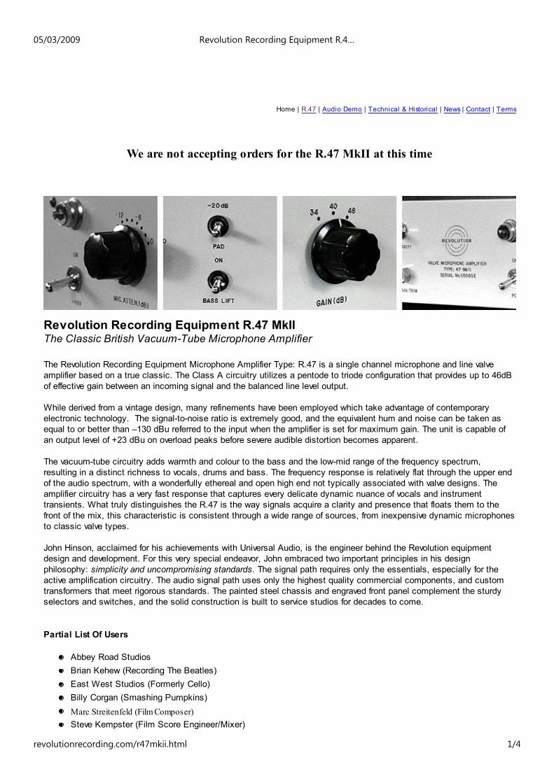
We are not accepting orders for the R.47 MkII at this time
Revolution Recording Equipment R.47 MkIIThe Classic British Vacuum-Tube Microphone Amplifier
The Revolution Recording Equipment Microphone Amplifier Type: R.47 is a single channel microphone and line valveamplifier based on a true classic. The Class A circuitry utilizes a pentode to triode configuration that provides up to 46dBof effective gain between an incoming signal and the balanced line level output.
While derived from a vintage design, many refinements have been employed which take advantage of contemporaryelectronic technology. The signal-to-noise ratio is extremely good, and the equivalent hum and noise can be taken asequal to or better than –130 dBu referred to the input when the amplifier is set for maximum gain. The unit is capable ofan output level of +23 dBu on overload peaks before severe audible distortion becomes apparent.
The vacuum-tube circuitry adds warmth and colour to the bass and the low-mid range of the frequency spectrum,resulting in a distinct richness to vocals, drums and bass. The frequency response is relatively flat through the upper endof the audio spectrum, with a wonderfully ethereal and open high end not typically associated with valve designs. Theamplifier circuitry has a very fast response that captures every delicate dynamic nuance of vocals and instrumenttransients. What truly distinguishes the R.47 is the way signals acquire a clarity and presence that floats them to thefront of the mix, this characteristic is consistent through a wide range of sources, from inexpensive dynamic microphonesto classic valve types.
John Hinson, acclaimed for his achievements with Universal Audio, is the engineer behind the Revolution equipmentdesign and development. For this very special endeavor, John embraced two important principles in his designphilosophy: simplicity and uncompromising standards. The signal path requires only the essentials, especially for theactive amplification circuitry. The audio signal path uses only the highest quality commercial components, and customtransformers that meet rigorous standards. The painted steel chassis and engraved front panel complement the sturdyselectors and switches, and the solid construction is built to service studios for decades to come.
Partial List Of Users
Abbey Road StudiosBrian Kehew (Recording The Beatles)East West Studios (Formerly Cello)Billy Corgan (Smashing Pumpkins)Marc Streitenfeld (Film Composer)Steve Kempster (Film Score Engineer/Mixer)
05/03/2009 Revolution Recording Equipment R.4…
revolutionrecording.com/r47mkii.html 1/4

Features
Hand assembled using only the finest components (Hovland, Caddock, Mills)Selected New Old Stock (NOS) vacuum tubesCustom made gold plated switches (ELMA)Massive, custom-wound input and output transformersFully regulated, over-designed H.T. & L.T. power suppliesSwitched gain and attenuator controls for repeatabilityCardas and Kimber chassis wiringNo silk-screen! - front panels are engraved and paintedThick, welded steel chassis for extreme durability
Specifications
Source Impedance: 200ohmsInput Loading Impedance: 2K ohms (attenuator off)Maximum Input Level @ 20 Hz: +7dBu (attenuator & pad off)Minimum Gain: -4dBMaximum Gain: +46dBFrequency Response: +/- 0.25dB 20Hz to 20kHz (high end -3dB point @ 48 kHz)Signal to Noise Ratio: 80dBEquivalent Input Noise: -130dBInternal Output Impedance: 50 ohmsSuggested Minimum Load: 450 ohmsMaximum Output Level: +23 dBuPower Requirements: 120 or 240 VAC, 50/60 HzDimensions: 19" W, 3.5" H, 7" DWeight: 19lbs
Details
Standard Single Channel R.47 MSRP: $3000.00 USDCustom Matched R.47 Units: Please InquireThe R.47 Microphone Amplifier is available only by special order at this timeDelivery Time: Please Inquire
R.47 SIGNAL DIAGRAM
05/03/2009 Revolution Recording Equipment R.4…
revolutionrecording.com/r47mkii.html 2/4

MIC. INPUT Balanced Microphone Input. Pin 2 [+] with switchable Phantom Power. 200 ohm Impedance.
MIC. ATTEN. Eleven Position Input Attenuator Network (Pad) with a range from -20dB to 0dB in 2dBincrements. The Microphone Attenuator is a Pad network that will change the impedance of theinput load. Subsequently, the increased impedance will change the character of the microphoneresponse changing the colour of the signal.
–10dB PAD On/Off Switch for fixed 10 dB input pad.
BASS LIFT A unique passive filter circuit to compensate for a loss in low frequencies when usingmicrophones with a figure-of-eight pick-up pattern.
AMPLIFIER The amplifier consists of two valve stages, resistance-capacitance coupled with two loops ofnegative feedback. In the block diagram, the input and output transformers are nested in theamplifier section.
GAINCONTROLS
Four Position Rotary Selector to control amplifier gain (frequency compensated) fixed at 34dB,40dB, and 46dB. The optimal setting for the Gain control is 40dB. Not only does this conform tothe original specifications, but it has the best colour for general purposes from vocal to instrumentrecording.
POLARITY The Polarity reverse switch reverses the output phase from Pin 2 [+] to Pin 3 [+]
OUTPUT Floating Balanced Line Level output. Pin 2 [+]
R.47 CONTROLS
1. MIC. ATTEN. (dB) Eleven Position Input Attenuator Network (Pad) with a range from -20dB to 0dB in 2dBincrements.
2. –10dB PAD On/Off Switch for fixed 10 dB input pad.
3. GAIN Four Position Rotary Selector to control amplifier gain (frequency compensated) fixed at34dB, 40dB, and 46dB.
4. POLARITY On/Off Switch for polarity (phase) reversal of the output signal.
5. +48V On/Off Switch for supplying phantom power (48V) to non-valve condenser microphones.
6. BASS LIFT On/Off Switch for a unique passive filter circuit to compensate for a loss in low frequencieswhen using microphones with a figure of 8 pick-up pattern.
7. GAIN TRIM Locked fine gain adjustment control for balancing gains of matched pairs of R.47 amplifiers. The range of adjustment depends on the setting of the main gain control (# 3 above) but isapprox. +/- 1 dB.
05/03/2009 Revolution Recording Equipment R.4…
revolutionrecording.com/r47mkii.html 3/4

8. STUDIOREGISTRATION
Custom units require component and tube matching. These are issued with the Studio Nameand Serial Number engraved on the front panel.
9. POWER On/Off switch for main AC power.
05/03/2009 Revolution Recording Equipment R.4…
revolutionrecording.com/r47mkii.html 4/4

http://revolutionrecording.com/images/Redd47SideView.jpg
http://revolutionrecording.com/images/Redd47SideView.jpg [05/03/2009 19:22:55]

http://revolutionrecording.com/images/REDD47Pair.jpg
http://revolutionrecording.com/images/REDD47Pair.jpg [05/03/2009 19:22:32]