EMC VSPEX Private Cloud Microsoft Windows Server 2012 with
208
Proven Infrastructure Guide EMC VSPEX Abstract This document describes the EMC ® VSPEX ® Proven Infrastructure solution for private cloud deployments with Microsoft Hyper-V, EMC VNX ® Series, and EMC Powered Backup for up to 1,000 virtual machines. April 2014 EMC VSPEX PRIVATE CLOUD Microsoft Windows Server 2012 R2 with Hyper-V for up to 1,000 Virtual Machines Enabled by EMC VNX Series and EMC Powered Backup
Transcript of EMC VSPEX Private Cloud Microsoft Windows Server 2012 with

Proven Infrastructure Guide
EMC VSPEX
Abstract
This document describes the EMC® VSPEX® Proven Infrastructure solution for private cloud deployments with Microsoft Hyper-V, EMC VNX® Series, and EMC Powered Backup for up to 1,000 virtual machines.
April 2014
EMC VSPEX PRIVATE CLOUD Microsoft Windows Server 2012 R2 with Hyper-V for up to 1,000 Virtual Machines Enabled by EMC VNX Series and EMC Powered Backup

2 EMC VSPEX Private Cloud: Microsoft Windows Server 2012 R2 with Hyper-V for up to 1,000 Virtual MachinesEnabled by EMC VNX Series and EMC Powered Backup Proven Infrastructure Guide
Copyright © 2014 EMC Corporation. All rights reserved. Published in the USA. Published April 2014
EMC believes the information in this publication is accurate as of its publication date. The information is subject to change without notice.
The information in this publication is provided as is. EMC Corporation makes no representations or warranties of any kind with respect to the information in this publication, and specifically disclaims implied warranties of merchantability or fitness for a particular purpose. Use, copying, and distribution of any EMC software described in this publication requires an applicable software license.
EMC2, EMC, and the EMC logo are registered trademarks or trademarks of EMC Corporation in the United States and other countries. All other trademarks used herein are the property of their respective owners.
For the most up-to-date regulatory document for your product line, go to the technical documentation and advisories section on the EMC Online Support website.
EMC VSPEX Private Cloud: Microsoft Windows Server 2012 R2 with Hyper-V for up to 1,000 Virtual Machines Enabled by EMC VNX Series and EMC Powered Backup Proven Infrastructure Guide
Part Number H12075.2

EMC VSPEX Private Cloud: Microsoft Windows Server 2012 R2 with Hyper-V for up to 1,000 Virtual Machines Enabled by EMC VNX Series and EMC Powered Backup
Proven Infrastructure Guide
3
Contents
Chapter 1 Executive Summary 15
Introduction ............................................................................................................. 16
Target audience ........................................................................................................ 16
Document purpose ................................................................................................... 16
Business needs ........................................................................................................ 17
Chapter 2 Solution Overview 19
Introduction ............................................................................................................. 20
Virtualization ............................................................................................................ 20
Compute .................................................................................................................. 20
Network .................................................................................................................... 20
Storage .................................................................................................................... 21
EMC VNX Series ................................................................................................... 22
EMC backup and recovery .................................................................................... 28
Chapter 3 Solution Technology Overview 31
Overview .................................................................................................................. 32
Summary of key components ................................................................................... 33
Virtualization ............................................................................................................ 34
Overview ............................................................................................................. 34
Microsoft Hyper-V ................................................................................................ 34
Virtual Fibre Channel ports .................................................................................. 34
Microsoft System Center Virtual Machine Manager .............................................. 34
High availability with Hyper-V Failover Clustering ................................................. 35
Hyper-V Replica ................................................................................................... 35
Hyper-V snapshot ................................................................................................ 36
Cluster-Aware Updating ....................................................................................... 36
EMC Storage Integrator ........................................................................................ 36
Compute .................................................................................................................. 37
Network .................................................................................................................... 39
Overview ............................................................................................................. 39

Contents
4 EMC VSPEX Private Cloud: Microsoft Windows Server 2012 R2 with Hyper-V for up to 1,000 Virtual Machines Enabled by EMC VNX Series and EMC Powered Backup Proven Infrastructure Guide
Storage .................................................................................................................... 41
Overview ............................................................................................................. 41
EMC VNX series ................................................................................................... 41
EMC VNX Snapshots ............................................................................................ 42
EMC VNX SnapSure .............................................................................................. 43
EMC VNX Virtual Provisioning............................................................................... 43
Windows Offloaded Data Transfer ........................................................................ 48
EMC PowerPath ................................................................................................... 49
EMC FAST Cache .................................................................................................. 49
VNX file shares .................................................................................................... 49
ROBO ................................................................................................................... 49
SMB 3.0 features ...................................................................................................... 50
Overview ............................................................................................................. 50
SMB versions and negotiations ........................................................................... 50
VNX and VNXe storage support ............................................................................ 50
SMB 3.0 VHD/VHDX storage support ................................................................... 51
SMB 3.0 Continuous Availability .......................................................................... 51
SMB Multichannel ............................................................................................... 53
SMB 3.0 Copy Offload .......................................................................................... 55
SMB 3.0 BranchCache ......................................................................................... 56
SMB 3.0 Remote VSS ........................................................................................... 57
SMB 3.0 encryption ............................................................................................. 58
SMB 3.0 PowerShell cmdlets ............................................................................... 60
SMB 3.0 Directory Leasing ................................................................................... 63
Summary of feature defaults ................................................................................ 65
Backup and recovery ................................................................................................ 65
Overview ............................................................................................................. 65
EMC Avamar deduplication .................................................................................. 65
EMC Data Domain deduplication storage systems ............................................... 65
VMware vSphere data protection ......................................................................... 65
Continuous availability ............................................................................................. 66
EMC RecoverPoint ................................................................................................ 66
EMC VNX Replicator ............................................................................................. 67
Other technologies ................................................................................................... 68
EMC XtremCache ................................................................................................. 68
Chapter 4 Solution Architecture Overview 71
Overview .................................................................................................................. 72
Solution architecture ................................................................................................ 72

Contents
EMC VSPEX Private Cloud: Microsoft Windows Server 2012 R2 with Hyper-V for up to 1,000 Virtual Machines Enabled by EMC VNX Series and EMC Powered Backup
Proven Infrastructure Guide
5
Overview ............................................................................................................. 72
Logical architecture ............................................................................................. 73
Key components .................................................................................................. 74
Hardware resources ............................................................................................. 76
Software resources .............................................................................................. 81
Server configuration guidelines ................................................................................ 82
Overview ............................................................................................................. 82
Ivy Bridge Updates ............................................................................................... 82
Hyper-V memory virtualization ............................................................................. 85
Memory configuration guidelines ......................................................................... 86
Network configuration guidelines ............................................................................. 87
Overview ............................................................................................................. 87
VLAN.................................................................................................................... 87
Enable jumbo frames (iSCSI, FCoE, or SMB only) .................................................. 89
Link aggregation (SMB only) ................................................................................ 90
Storage configuration guidelines .............................................................................. 90
Overview ............................................................................................................. 90
Hyper-V storage virtualization for VSPEX .............................................................. 93
VSPEX storage building blocks ............................................................................ 95
VSPEX private cloud validated maximums ........................................................... 96
High-availability and failover .................................................................................. 105
Overview ........................................................................................................... 105
Virtualization layer ............................................................................................. 105
Compute layer ................................................................................................... 105
Network layer .................................................................................................... 106
Storage layer ..................................................................................................... 106
Validation test profile ............................................................................................. 107
Profile characteristics ........................................................................................ 107
Backup and recovery configuration guidelines ....................................................... 108
Sizing guidelines .................................................................................................... 108
Reference workload ................................................................................................ 108
Overview ........................................................................................................... 108
Defining the reference workload ........................................................................ 108
Applying the reference workload ............................................................................ 109
Overview ........................................................................................................... 109
Example 1: Custom-built application ................................................................. 109
Example 2: Point-of-Sale system ........................................................................ 110
Example 3: Web server ...................................................................................... 110
Example 4: Decision-support database .............................................................. 110

Contents
6 EMC VSPEX Private Cloud: Microsoft Windows Server 2012 R2 with Hyper-V for up to 1,000 Virtual Machines Enabled by EMC VNX Series and EMC Powered Backup Proven Infrastructure Guide
Summary of examples ....................................................................................... 111
Implementing the solution ..................................................................................... 111
Overview ........................................................................................................... 111
Resource types .................................................................................................. 111
CPU resources ................................................................................................... 111
Memory resources ............................................................................................. 112
Network resources ............................................................................................. 112
Storage resources .............................................................................................. 113
Implementation summary .................................................................................. 113
Quick assessment of customer environment .......................................................... 114
Overview ........................................................................................................... 114
CPU requirements .............................................................................................. 114
Memory requirements ........................................................................................ 115
Storage performance requirements .................................................................... 115
IOPS .................................................................................................................. 115
I/O size .............................................................................................................. 115
I/O latency ......................................................................................................... 116
Storage capacity requirements .......................................................................... 116
Determining equivalent reference virtual machines ........................................... 116
Fine-tuning hardware resources ......................................................................... 123
EMC VSPEX Sizing Tool ...................................................................................... 126
Chapter 5 VSPEX Configuration Guidelines 127
Overview ................................................................................................................ 128
Pre-deployment tasks ............................................................................................. 129
Overview ........................................................................................................... 129
Deployment prerequisites .................................................................................. 129
Customer configuration data .................................................................................. 130
Prepare switches, connect network, and configure switches ................................... 131
Overview ........................................................................................................... 131
Prepare network switches .................................................................................. 131
Configure infrastructure network ........................................................................ 131
Configure VLANs ................................................................................................ 133
Configure jumbo frames (iSCSI or SMB only) ...................................................... 133
Complete network cabling ................................................................................. 134
Prepare and configure storage array ....................................................................... 134
VNX configuration for block protocols ................................................................ 134
VNX configuration for file protocols .................................................................... 137
FAST VP configuration ........................................................................................ 146

Contents
EMC VSPEX Private Cloud: Microsoft Windows Server 2012 R2 with Hyper-V for up to 1,000 Virtual Machines Enabled by EMC VNX Series and EMC Powered Backup
Proven Infrastructure Guide
7
FAST Cache configuration .................................................................................. 148
Install and configure Hyper-V hosts ........................................................................ 151
Overview ........................................................................................................... 151
Install Windows hosts ........................................................................................ 151
Install Hyper-V and configure failover clustering ................................................ 151
Configure Windows host networking .................................................................. 152
Install PowerPath on Windows servers ............................................................... 152
Plan virtual machine memory allocations ........................................................... 152
Install and configure SQL Server database ............................................................. 153
Overview ........................................................................................................... 153
Create a virtual machine for Microsoft SQL Server .............................................. 153
Install Microsoft Windows on the virtual machine .............................................. 153
Install SQL Server .............................................................................................. 153
Configure a SQL Server for SCVMM .................................................................... 154
System Center Virtual Machine Manager server deployment ................................... 154
Overview ........................................................................................................... 154
Create a SCVMM host virtual machine ............................................................... 155
Install the SCVMM guest OS .............................................................................. 155
Install the SCVMM server ................................................................................... 155
Install the SCVMM Management Console ........................................................... 156
Install the SCVMM agent locally on a host ......................................................... 156
Add a Hyper-V cluster into SCVMM .................................................................... 156
Add file share storage to SCVMM (file variant only) ............................................ 156
Create a virtual machine in SCVMM ................................................................... 156
Perform partition alignment, and assign File Allocation Unite Size ..................... 156
Create a template virtual machine ..................................................................... 156
Deploy virtual machines from the template virtual machine ............................... 157
Summary ................................................................................................................ 157
Chapter 6 Verifying the Solution 159
Overview ................................................................................................................ 160
Post-install checklist .............................................................................................. 161
Deploy and test a single virtual server .................................................................... 161
Verify the redundancy of the solution components ................................................. 161
Block environments ........................................................................................... 161
File environments .............................................................................................. 162
Chapter 7 System Monitoring 163
Overview ................................................................................................................ 164
Key areas to monitor ............................................................................................... 164

Contents
8 EMC VSPEX Private Cloud: Microsoft Windows Server 2012 R2 with Hyper-V for up to 1,000 Virtual Machines Enabled by EMC VNX Series and EMC Powered Backup Proven Infrastructure Guide
Performance baseline ........................................................................................ 164
Servers .............................................................................................................. 165
Networking ........................................................................................................ 165
Storage .............................................................................................................. 165
VNX resources monitoring guidelines ..................................................................... 166
Monitoring block storage resources ................................................................... 166
Monitoring file storage resources ....................................................................... 174
Summary ........................................................................................................... 179
Chapter 8 Validation with Microsoft Fast Track v3 181
Overview ................................................................................................................ 182
Business case for validation ................................................................................... 182
Process requirements ............................................................................................. 183
Step 1: Core prerequisites ................................................................................. 183
Step 2: Select the VSPEX Proven Infrastructure platform .................................... 183
Step 3: Define additional Microsoft Hyper-V Fast Track Program components .... 183
Step 4: Build a detailed bill of materials ............................................................ 184
Step 5: Test the environment ............................................................................. 185
Step 6: Document and publish the solution ....................................................... 185
Additional resources .............................................................................................. 185
Appendix A Bill of Materials 187
Bill of materials ...................................................................................................... 188
Appendix B Customer Configuration Data Sheet 197
Customer configuration data sheet ......................................................................... 198
Appendix C Server Resources Component Worksheet 201
Server resources component worksheet ................................................................. 202
Appendix D References 203
References ............................................................................................................. 204
EMC documentation .......................................................................................... 204
Other documentation......................................................................................... 204
Appendix E About VSPEX 207
About VSPEX .......................................................................................................... 208

EMC VSPEX Private Cloud: Microsoft Windows Server 2012 R2 with Hyper-V for up to 1,000 Virtual Machines Enabled by EMC VNX Series and EMC Powered Backup
Proven Infrastructure Guide
9
Figures
Figure 1. Next-Generation VNX with multicore optimization................................ 23
Figure 2. Active/active processors increase performance, resiliency, and efficiency ............................................................................................. 24
Figure 3. New Unisphere Management Suite ...................................................... 25
Figure 4. Storage Processor utilization using Windows deduplication ................ 26
Figure 5. Disk IOPS using Windows deduplication ............................................. 27
Figure 6. Disk latency using Windows deduplication .......................................... 27
Figure 7. Deduplication efficiency using VNX deduplication ............................... 28
Figure 8. Deduplication efficiency using Windows Server 2012 R2 deduplication28
Figure 9. EMC backup and recovery solutions .................................................... 29
Figure 10. VSPEX private cloud components ........................................................ 32
Figure 11. Compute layer flexibility ...................................................................... 37
Figure 12. Example of highly available network design – for block ....................... 39
Figure 13. Example of highly available network design – for file ........................... 40
Figure 14. Storage pool rebalance progress ......................................................... 44
Figure 15. Thin LUN space utilization ................................................................... 45
Figure 16. Examining storage pool space utilization............................................. 46
Figure 17. Defining storage pool utilization thresholds ........................................ 47
Figure 18. Defining automated notifications - for block ........................................ 47
Figure 19. SMB 3.0 baseline performance comparison point ............................... 51
Figure 20. SMB 3.0 Continuous Availability .......................................................... 52
Figure 21. CA – application performance ............................................................. 53
Figure 22. SMB Multichannel fault tolerance ........................................................ 54
Figure 23. Multichannel network throughput........................................................ 55
Figure 24. Copy Offload ....................................................................................... 55
Figure 25. Enabling the Encrypt Data parameter ................................................... 59
Figure 26. Enabling encryption: Client CPU utilization .......................................... 60
Figure 27. Enabling encryption: Data Mover CPU utilization ................................. 60
Figure 28. PowerShell execution of Show Shares ................................................. 62
Figure 29. PowerShell execution of Get-SmbServerConfiguration ......................... 63

Figures
10 EMC VSPEX Private Cloud: Microsoft Windows Server 2012 R2 with Hyper-V for up to 1,000 Virtual Machines Enabled by EMC VNX Series and EMC Powered Backup Proven Infrastructure Guide
Figure 30. SMB 3.0 Directory Leasing ................................................................... 64
Figure 31. Logical architecture for block storage .................................................. 73
Figure 32. Logical architecture for file storage ...................................................... 74
Figure 33. Ivy Bridge processor guidance ............................................................. 82
Figure 34. Hypervisor memory consumption ........................................................ 85
Figure 35. Required networks for block storage .................................................... 88
Figure 36. Required networks for file storage ....................................................... 89
Figure 37. Hyper-V virtual disk types .................................................................... 93
Figure 38. Building block for 13 virtual servers .................................................... 95
Figure 39. Building block for 125 virtual servers .................................................. 96
Figure 40. Storage layout for 200 virtual machines using VNX 5200 ..................... 98
Figure 41. Storage layout for 300 virtual machines using VNX5400 ...................... 99
Figure 42. Storage layout for 600 virtual machines using VNX5600 .................... 101
Figure 43. Storage layout for 1,000 virtual machines using VNX5800................. 103
Figure 44. Maximum scale levels and entry points of different arrays ................. 104
Figure 45. High availability at the virtualization layer ......................................... 105
Figure 46. Redundant power supplies ................................................................ 105
Figure 47. Network layer high availability (VNX) – block variant ......................... 106
Figure 48. Network layer high availability (VNX) – file variant ............................. 106
Figure 49. VNX series HA components................................................................ 107
Figure 50. Resource pool flexibility .................................................................... 111
Figure 51. Required resource from the reference virtual machine pool ............... 117
Figure 52. Aggregate resource requirements – stage 1 ....................................... 119
Figure 53. Pool configuration – stage 1 .............................................................. 119
Figure 54. Aggregate resource requirements - stage 2 ........................................ 121
Figure 55. Pool configuration – stage 2 .............................................................. 121
Figure 56. Aggregate resource requirements for stage 3 ..................................... 123
Figure 57. Pool configuration – stage 3 .............................................................. 123
Figure 58. Customizing server resources ............................................................ 124
Figure 59. Sample Ethernet network architecture - block variant ........................ 132
Figure 60. Sample Ethernet network architecture - file variant ............................ 133
Figure 61. Network Settings for File dialog box ................................................... 139
Figure 62. The Create Interface dialog box.......................................................... 140
Figure 63. The Create CIFS Server dialog box ...................................................... 141
Figure 64. The Create File System dialog box...................................................... 144
Figure 65. The File System Properties dialog box ................................................ 145
Figure 66. The Create File Share dialog box ........................................................ 146
Figure 67. The Storage Pool Properties dialog box .............................................. 147
Figure 68. Manage Auto-Tiering dialog box ........................................................ 147
Figures
EMC VSPEX Private Cloud: Microsoft Windows Server 2012 R2 with Hyper-V for up to 1,000 Virtual Machines Enabled by EMC VNX Series and EMC Powered Backup
Proven Infrastructure Guide
11
Figure 69. The Storage System Properties dialog box ......................................... 148
Figure 70. The Create FAST Cache dialog box ..................................................... 149
Figure 71. Advanced tab in the Create Storage Pool dialog ................................. 150
Figure 72. Advanced tab in the Storage Pool Properties dialog ........................... 150
Figure 73. Storage Pool Alerts area .................................................................... 167
Figure 74. Storage Pools panel .......................................................................... 168
Figure 75. LUN Properties dialog box ................................................................. 169
Figure 76. Monitoring and Alerts panel .............................................................. 170
Figure 77. IOPS on the LUNs .............................................................................. 171
Figure 78. IOPS on the disks .............................................................................. 172
Figure 79. Latency on the LUNs .......................................................................... 172
Figure 80. SP utilization ..................................................................................... 174
Figure 81. Data Mover statistics ......................................................................... 175
Figure 82. Front-end Data Mover network statistics ............................................ 175
Figure 83. Storage Pools for File panel ............................................................... 176
Figure 84. File Systems panel ............................................................................. 176
Figure 85. File System Properties window .......................................................... 177
Figure 86. File System I/O Statistics window ...................................................... 178
Figure 87. CIFS Statistics window ....................................................................... 179

Tables
12 EMC VSPEX Private Cloud: Microsoft Windows Server 2012 R2 with Hyper-V for up to 1,000 Virtual Machines Enabled by EMC VNX Series and EMC Powered Backup Proven Infrastructure Guide
Tables
Table 1. VNX customer benefits ........................................................................ 41
Table 2. Thresholds and settings under VNX OE Block Release 33 .................... 48
Table 3. SMB dialect used between client and server ........................................ 50
Table 4. Storage migration improvement with Copy Offload .............................. 56
Table 5. Microsoft PowerShell cmdlets ............................................................. 61
Table 6. EMC-provided PowerShell cmdlets ...................................................... 61
Table 7. Default status of SMB 3.0 features ...................................................... 65
Table 8. Solution hardware ............................................................................... 76
Table 9. Solution software ................................................................................ 81
Table 10. Hardware resources for compute layer ................................................. 83
Table 11. Hardware resources for network .......................................................... 87
Table 12. Hardware resources for storage ........................................................... 91
Table 13. Number of disks required for different number of virtual machines ...... 96
Table 14. Profile characteristics ........................................................................ 107
Table 15. Virtual machine characteristics.......................................................... 109
Table 16. Blank worksheet row ......................................................................... 114
Table 17. Reference virtual machine resources ................................................. 116
Table 18. Example worksheet row ..................................................................... 117
Table 19. Example applications – stage 1 ......................................................... 118
Table 20. Example applications - stage 2 .......................................................... 120
Table 21. Example applications - stage 3 .......................................................... 121
Table 22. Server resource component totals ..................................................... 124
Table 23. Deployment process overview ........................................................... 128
Table 24. Tasks for pre-deployment .................................................................. 129
Table 25. Deployment prerequisites checklist ................................................... 129
Table 26. Tasks for switch and network configuration ....................................... 131
Table 27. Tasks for VNX configuration for block protocols ................................. 134
Table 28. Storage allocation table for block ...................................................... 136
Table 29. Tasks for storage configuration for file protocols ............................... 137
Table 30. Storage allocation table for file .......................................................... 142

Tables
EMC VSPEX Private Cloud: Microsoft Windows Server 2012 R2 with Hyper-V for up to 1,000 Virtual Machines Enabled by EMC VNX Series and EMC Powered Backup
Proven Infrastructure Guide
13
Table 31. Tasks for server installation ............................................................... 151
Table 32. Tasks for SQL Server database setup ................................................. 153
Table 33. Tasks for SCVMM configuration ......................................................... 154
Table 34. Hyper-V Fast Track component classification ..................................... 183
Table 35. List of components used in the VSPEX solution for 200 virtual machines .................................................................... 188
Table 36. List of components used in the VSPEX solution for 300 virtual machines ................................................................... 190
Table 37. List of components used in the VSPEX solution for 600 virtual machines .................................................................... 192
Table 38. List of components used in the VSPEX solution for 1,000 virtual machines ................................................................. 194
Table 39. Common server information .............................................................. 198
Table 40. Hyper-V server information ............................................................... 198
Table 41. Array information ............................................................................... 199
Table 42. Network infrastructure information .................................................... 199
Table 43. VLAN information .............................................................................. 200
Table 44. Service accounts ............................................................................... 200
Table 45. Blank worksheet for determining server resources ............................. 202


EMC VSPEX Private Cloud: Microsoft Windows Server 2012 R2 with Hyper-V for up to 1,000 Virtual Machines Enabled by EMC VNX Series and EMC Powered Backup
Proven Infrastructure Guide
15
Chapter 1 Executive Summary
This chapter presents the following topics:
Introduction ............................................................................................................. 16
Target audience ....................................................................................................... 16
Document purpose ................................................................................................... 16
Business needs ........................................................................................................ 17

Executive Summary
16 EMC VSPEX Private Cloud: Microsoft Windows Server 2012 R2 with Hyper-V for up to 1,000 Virtual Machines Enabled by EMC VNX Series and EMC Powered Backup Proven Infrastructure Guide
Introduction
Validated EMC® VSPEX® modular architectures are built with proven superior technologies to create complete virtualization solutions. These solutions enable you to make an informed decision in the hypervisor, compute, backup, storage, and networking layers. VSPEX helps to reduce virtualization planning and configuration burdens. When embarking on server virtualization, virtual desktop deployment, or IT consolidation, VSPEX accelerates your IT transformation by enabling faster deployments, expanded choices, greater efficiency, and lower risk.
This document is a comprehensive guide to the technical aspects of this solution. Server capacity is provided in generic terms for required minimums of CPU, memory, and network interfaces; the customer is free to select the server and networking hardware that meet or exceed the stated minimums.
Target audience
The readers of this document should have the necessary training and background to install and configure a VSPEX computing solution based on Microsoft Hyper-V as a hypervisor, EMC VNX® series storage systems, and associated infrastructure as required by this implementation. External references are provided where applicable, and the readers should be familiar with these documents.
Readers should also be familiar with the infrastructure and database security policies of the customer’s existing installation.
Individuals focusing on selling and sizing a VSPEX end-user computing solution for Microsoft Hyper-V private cloud infrastructure must pay particular attention to the first four chapters of this document. After purchase, implementers of the solution should focus on the configuration guidelines in Chapter 5, the solution validation in Chapter 6, and the appropriate references and appendices.
Document purpose
This proven infrastructure guide includes an initial introduction to the VSPEX architecture, an explanation of how to modify the architecture for specific engagements, and instructions on how to effectively deploy and monitor the system.
The VSPEX private cloud architecture provides the customer with a modern system capable of hosting many virtual machines at a consistent performance level. This solution runs on the Microsoft Hyper-V virtualization layer backed by the highly available VNX family of storage. The compute and network components, which are defined by the VSPEX partners, are laid out to be redundant and sufficiently powerful to handle the processing and data needs of the virtual machine environment.
The environments for 200, 300, 600, and 1,000 virtual machines are based on a defined reference workload. Since not every virtual machine has the same requirements, this document contains methods and guidance to adjust your system to be cost-effective when deployed. For smaller environments, solutions for up to 100 virtual machines based on the EMC VNXe® series are described in the EMC VSPEX

Executive Summary
EMC VSPEX Private Cloud: Microsoft Windows Server 2012 R2 with Hyper-V for up to 1,000 Virtual Machines Enabled by EMC VNX Series and EMC Powered Backup
Proven Infrastructure Guide
17
Private Cloud: Microsoft Windows Server 2012 with Hyper-V for up to 125 Virtual Machines Proven Infrastructure Guide.
A private cloud architecture is a complex system offering. This document facilitates its setup by providing up-front software and hardware material lists, step-by-step sizing guidance and worksheets, and verified deployment steps. After the last component has been installed, validation tests and monitoring instructions ensure that your customer’s system is running correctly. Following the instructions in this document ensures an efficient and expedited journey to the cloud.
Business needs
Business applications are moving into consolidated compute, network, and storage environments. EMC VSPEX private cloud solutions using Microsoft Hyper-V reduce the complexity of configuring every component of a traditional deployment model. The complexity of integration management is reduced while maintaining the application design flexibility and implementation options. Administration is unified, while process separation can be adequately controlled and monitored. The business needs for the VSPEX private cloud solutions for Microsoft Hyper-V architectures are:
Provide an end-to-end virtualization solution to effectively utilize the capabilities of the unified infrastructure components.
Provide a VSPEX private cloud solution for Microsoft Hyper-V to efficiently virtualize up to 1,000 virtual machines for varied customer use cases.
Provide a reliable, flexible, and scalable reference design.
Executive Summary
18 EMC VSPEX Private Cloud: Microsoft Windows Server 2012 R2 with Hyper-V for up to 1,000 Virtual Machines Enabled by EMC VNX Series and EMC Powered Backup Proven Infrastructure Guide

EMC VSPEX Private Cloud: Microsoft Windows Server 2012 R2 with Hyper-V for up to 1,000 Virtual Machines Enabled by EMC VNX Series and EMC Powered Backup
Proven Infrastructure Guide
19
Chapter 2 Solution Overview
This chapter presents the following topics:
Introduction ............................................................................................................. 20
Virtualization ........................................................................................................... 20
Compute................................................................................................................... 20
Network ................................................................................................................... 20
Storage .................................................................................................................... 21

Solution Overview
20 EMC VSPEX Private Cloud: Microsoft Windows Server 2012 R2 with Hyper-V for up to 1,000 Virtual Machines Enabled by EMC VNX Series and EMC Powered Backup Proven Infrastructure Guide
Introduction
The EMC VSPEX private cloud for Microsoft Hyper-V provides complete system architecture capable of supporting up to 1,000 virtual machines with a redundant server or network topology and highly available storage. The core components that make up this particular solution are virtualization, compute, backup, storage, and networking.
Virtualization
Microsoft Hyper-V is a key virtualization platform in the industry. For years, Hyper-V has provided flexibility and cost savings to end users by consolidating large, inefficient server farms into nimble, reliable cloud infrastructures.
Features such as Live Migration, which enables a virtual machine to move between different servers with no disruption to the guest operating system, and Dynamic Optimization, which performs Live Migrations automatically to balance loads, make Hyper-V a solid business choice.
With the release of Windows Server 2012 R2, a Microsoft virtualized environment can host virtual machines with up to 64 virtual CPUs and 1 TB of virtual random access memory (RAM).
Compute
VSPEX provides the flexibility to design and implement the customer’s choice of server components. The infrastructure must conform to the following attributes:
Sufficient cores and memory to support the required number and types of virtual machines
Sufficient network connections to enable redundant connectivity to the system switches
Excess capacity to withstand a server failure and failover within the environment
Network
VSPEX provides the flexibility to design and implement the customer’s choice of network components. The infrastructure must conform to the following attributes:
Redundant network links for the hosts, switches, and storage
Traffic isolation based on industry-accepted best practices
Support for link aggregation
IP network switches used to implement this reference architecture must have a minimum non-blocking backplane capacity which is sufficient for the target number of virtual machines and their associated workloads. Enterprise-class

Solution Overview
EMC VSPEX Private Cloud: Microsoft Windows Server 2012 R2 with Hyper-V for up to 1,000 Virtual Machines Enabled by EMC VNX Series and EMC Powered Backup
Proven Infrastructure Guide
21
switches with advanced features such as Quality of Service are highly recommended.
Storage
The VNX storage series provides both file and block access with a broad feature set, which makes it an ideal choice for any private cloud implementation.
VNX storage includes the following components, sized for the stated reference architecture workload:
Host adapter ports (For block) – Provide host connectivity through fabric to the array
Storage processors – The compute components of the storage array, which are used for all aspects of data moving into, out of, and between arrays
Disk drives – Disk spindles and solid state drives (SSDs) that contain the host or application data and their enclosures
Data Movers (For file)– Front-end appliances that provide file services to hosts (optional if CIFS services are provided)
Note: The term Data Mover refers to a VNX hardware component, which has a CPU, memory, and I/O ports. It enables Common Internet File System (CIFS-SMB) and Network File System (NFS) protocols on the VNX.
The Microsoft Hyper-V private cloud solutions for 200, 300, 600, and 1,000 virtual machines described in this document are based on the EMC VNX5200™, VNX5400™, EMC VNX5600™ and the EMC VNX5800™ storage arrays respectively. The VNX5200 array can support a maximum of 125 drives, the VNX5400 array can support a maximum of 250 drives, the VNX5600 can host up to 500 drives, and the VNX5800 can host up to 750 drives.
The VNX series supports a wide range of business-class features that are ideal for the private cloud environment, including:
EMC Fully Automated Storage Tiering for Virtual Pools (FAST VP™)
EMC FAST Cache
File-level data deduplication and compression
Block deduplication
Thin provisioning
Replication
Snapshots or checkpoints
File-level retention
Quota management
Block compression

Solution Overview
22 EMC VSPEX Private Cloud: Microsoft Windows Server 2012 R2 with Hyper-V for up to 1,000 Virtual Machines Enabled by EMC VNX Series and EMC Powered Backup Proven Infrastructure Guide
Features and Enhancements
The EMC VNX flash-optimized unified storage platform delivers innovation and enterprise capabilities for file, block, and object storage in a single, scalable, and easy-to-use solution. Ideal for mixed workloads in physical or virtual environments, VNX combines powerful and flexible hardware with advanced efficiency, management, and protection software to meet the demanding needs of today’s virtualized application environments.
VNX includes many features and enhancements designed and built upon the first generation’s success. These features and enhancements include:
More capacity with multicore optimization through the use of Multicore Cache, Multicore RAID, and Multicore FAST Cache (MCx)
Greater efficiency with a flash-optimized hybrid array
Better protection by increasing application availability with active/active storage processors
Easier administration and deployment by increasing productivity with a new Unisphere Management Suite
VSPEX is built with the next generation of VNX to deliver even greater efficiency, performance, and scale than ever before.
Flash-optimized hybrid array
VNX is a flash-optimized hybrid array that provides automated tiering to deliver the best performance to your critical data, while intelligently moving less frequently accessed data to lower-cost disks.
In this hybrid approach, a small percentage of flash drives in the overall system can provide a high percentage of the overall IOPS. A flash-optimized VNX takes full advantage of the low latency of flash to deliver cost-saving optimization and high performance scalability. The EMC Fully Automated Storage Tiering Suite (FAST Cache and FAST VP) tiers both block and file data across heterogeneous drives and promotes the most active data to the flash drives, ensuring that customers never have to make concessions for cost or performance.
Data is typically used most frequently at the time it is created; therefore new data is first stored on flash drives for the best performance. As that data ages and becomes less active over time, FAST VP moves the data from high-performance to high-capacity drives automatically, based on customer-defined policies. EMC has enhanced this functionality with four times better granularity and with new FAST VP solid-state disks (SSDs) based on enterprise multi-level cell (eMLC) technology to lower the cost per gigabyte. FAST Cache assists performance by dynamically absorbing unpredicted spikes in system workloads. All VSPEX use cases benefit from the increased efficiency.
VSPEX Proven Infrastructures deliver private cloud, end-user computing, and virtualized application solutions. With VNX, customers can realize an even greater return on their investment. VNX also provides out-of-band, block-based deduplication that can dramatically lower the costs of the flash tier.
EMC VNX Series

Solution Overview
EMC VSPEX Private Cloud: Microsoft Windows Server 2012 R2 with Hyper-V for up to 1,000 Virtual Machines Enabled by EMC VNX Series and EMC Powered Backup
Proven Infrastructure Guide
23
VNX Intel MCx Code Path Optimization
The advent of flash technology has been a catalyst in totally changing the requirements of midrange storage systems. EMC redesigned the midrange storage platform to efficiently optimize multicore CPUs to provide the highest performing storage system at the lowest cost in the market.
MCx distributes all VNX data services across all cores—up to 32, as shown in Figure 1. The VNX series with MCx has dramatically improved the file performance for transactional applications like databases or virtual machines over network-attached storage (NAS).
Figure 1. Next-Generation VNX with multicore optimization
Multicore Cache The cache is the most valuable asset in the storage subsystem; its efficient use is key to the overall efficiency of the platform in handling variable and changing workloads. The cache engine has been modularized to take advantage of all the cores available in the system. Multicore RAID Another important part of the MCx redesign is the handling of I/O to the permanent back-end storage—hard disk drives (HDDs) and SSDs. Greatly increased performance improvements in VNX come from the modularization of the back-end data management processing, which enables MCx to seamlessly scale across all processors.
VNX performance
Performance enhancements VNX storage, enabled with the MCx architecture, is optimized for FLASH 1st and provides unprecedented overall performance, optimizing for transaction performance (cost per IOPS), bandwidth performance (cost per GB/s) with low latency, and providing optimal capacity efficiency (cost per GB).

Solution Overview
24 EMC VSPEX Private Cloud: Microsoft Windows Server 2012 R2 with Hyper-V for up to 1,000 Virtual Machines Enabled by EMC VNX Series and EMC Powered Backup Proven Infrastructure Guide
VNX provides the following performance improvements:
Up to four times more file transactions when compared with dual controller arrays
Increased file performance for transactional applications by up to three times, with a 60 percent better response time
Up to four times more Oracle and Microsoft SQL Server OLTP transactions
Up to six times more virtual machines
Active/active array storage processors
The new VNX architecture provides active/active array storage processors, as shown in Figure 2, which eliminate application timeouts during path failover since both paths are actively serving I/O.
Figure 2. Active/active processors increase performance, resiliency, and efficiency
Load balancing is also improved and applications can achieve an up to two times improvement in performance. Active/active for block is ideal for applications that require the highest levels of availability and performance, but do not require tiering or efficiency services like compression or deduplication.
With this VNX release, VSPEX customers can use virtual Data Movers (VDMs) and VNX Replicator to perform automated and high-speed file system migrations between systems. This process migrates all snaps and settings automatically, and enables the clients to continue operation during the migration.
Note: The active/active processors are only available for RAID logical unit numbers (LUNs), not for pool LUNs.
Unisphere Management Suite
The new Unisphere Management Suite extends Unisphere’s easy-to-use, interface to include VNX Monitoring and Reporting for validating performance and anticipating capacity requirements. As shown in Figure 3, the suite also includes Unisphere

Solution Overview
EMC VSPEX Private Cloud: Microsoft Windows Server 2012 R2 with Hyper-V for up to 1,000 Virtual Machines Enabled by EMC VNX Series and EMC Powered Backup
Proven Infrastructure Guide
25
Remote for centrally managing up to thousands of VNX and VNXe systems with new support for XtremCache products.
Figure 3. New Unisphere Management Suite
Virtualization Management
EMC Storage Integrator EMC Storage Integrator (ESI) is targeted towards the Windows and application administrator. ESI is easy to use, delivers end-to end monitoring, and is hypervisor agnostic. Administrators can provision in both virtual and physical environments for a Windows platform, and troubleshoot by viewing the topology of an application from the underlying hypervisor to the storage.
Microsoft Hyper-V With Windows Server 2012, Microsoft provides Hyper-V 3.0, an enhanced hypervisor for private cloud that can run on NAS protocols for simplified connectivity.
Offloaded Data Transfer The Offloaded Data Transfer (ODX) feature of Microsoft Hyper-V enables data transfers during copy operations to be offloaded to the storage array, freeing up host cycles. For example, using ODX for a live migration of a SQL Server virtual machine doubled performance, decreased migration time by 50 percent, reduced CPU on the Hyper-V server by 20 percent, and eliminated network traffic.
Block deduplication Native block deduplication was introduced in Windows Server 2012, and the R2 release contained minor improvements to the offering. It is important to understand the impact of using OS-based deduplication on overall VSPEX performance and this becomes critical if array-based deduplication is enabled. Lab testing has created the following guidance:
If deduplication is enabled, either within the array or within the OS, FAST Cache significantly reduces the overhead impact and minimizes impact on latency; it is considered a best-practice to enable FAST Cache if deduplication is enabled within a VSPEX environment.
Solution Overview
26 EMC VSPEX Private Cloud: Microsoft Windows Server 2012 R2 with Hyper-V for up to 1,000 Virtual Machines Enabled by EMC VNX Series and EMC Powered Backup Proven Infrastructure Guide
VNX array based deduplication provided significantly better deduplication results (~2x improvement in space savings) and proved beneficial to a wider range of workloads than OS-based deduplication.
Do not enable OS-based and VNX array-based deduplication on the same LUNs
Ensure that the allocation unit size matches the I/O size of the workload. Failure to do so may result in non-optimal deduplication savings.
Windows deduplication will not start if the LUN contains less than 64 GB of data.
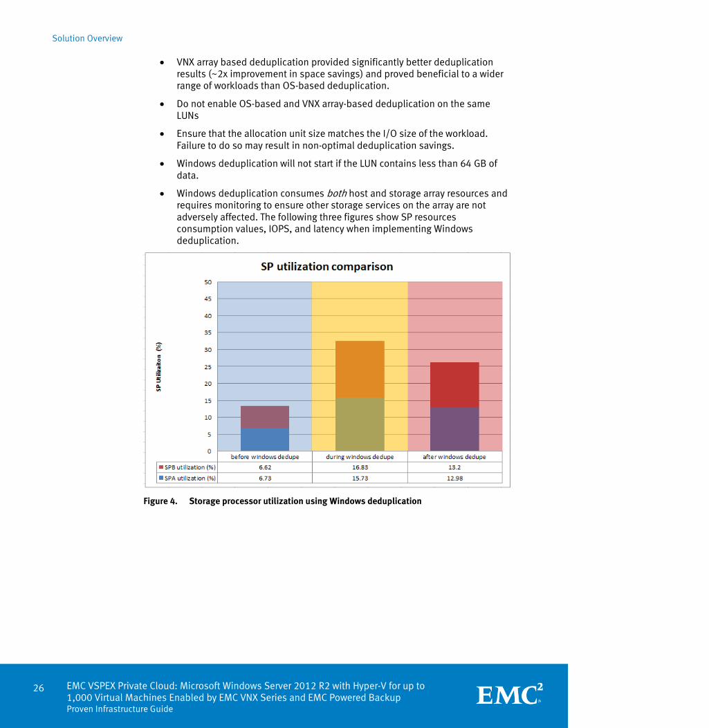
Windows deduplication consumes both host and storage array resources and requires monitoring to ensure other storage services on the array are not adversely affected. The following three figures show SP resources consumption values, IOPS, and latency when implementing Windows deduplication.
Figure 4. Storage processor utilization using Windows deduplication

Solution Overview
EMC VSPEX Private Cloud: Microsoft Windows Server 2012 R2 with Hyper-V for up to 1,000 Virtual Machines Enabled by EMC VNX Series and EMC Powered Backup
Proven Infrastructure Guide
27
Figure 5. Disk IOPS using Windows deduplication
Figure 6. Disk latency using Windows deduplication

Solution Overview
28 EMC VSPEX Private Cloud: Microsoft Windows Server 2012 R2 with Hyper-V for up to 1,000 Virtual Machines Enabled by EMC VNX Series and EMC Powered Backup Proven Infrastructure Guide
Figure 7. Deduplication efficiency using VNX deduplication
Figure 8. Deduplication efficiency using Windows Server 2012 R2 deduplication
EMC backup and recovery solutions, EMC Avamar and EMC Data Domain, deliver the protection confidence needed to accelerate the deployment of VSPEX private clouds.
Optimized for virtual environments, EMC backup and recovery reduces backup times by 90 percent and increases recovery speeds by 30 times, even offering virtual machines instant access for worry-free protection. EMC backup appliances add another layer of assurance with end-to-end verification and self-healing to ensure successful recoveries.
Our solutions also deliver big saving. With industry-leading deduplication, you can reduce backup storage by 10 to 30 times, backup management time by 81 percent, and WAN bandwidth by 99 percent for efficient disaster recovery, delivering a seven-month payback period on average. You will be able to scale storage easily and efficiently as your environment grows.
EMC backup and recovery
Solution Overview
EMC VSPEX Private Cloud: Microsoft Windows Server 2012 R2 with Hyper-V for up to 1,000 Virtual Machines Enabled by EMC VNX Series and EMC Powered Backup
Proven Infrastructure Guide
29
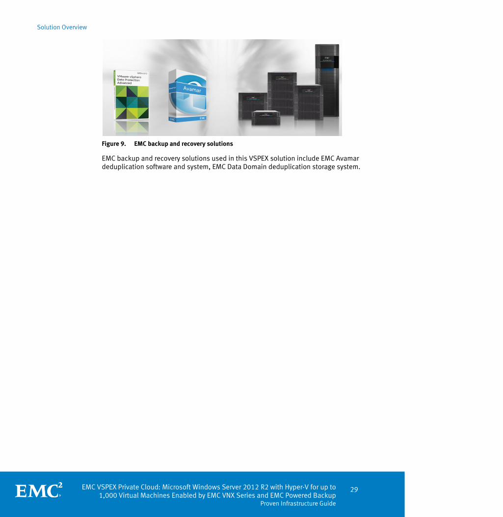
Figure 9. EMC backup and recovery solutions
EMC backup and recovery solutions used in this VSPEX solution include EMC Avamar deduplication software and system, EMC Data Domain deduplication storage system.

EMC VSPEX Private Cloud: Microsoft Windows Server 2012 R2 with Hyper-V for up to 1,000 Virtual Machines Enabled by EMC VNX Series and EMC Powered Backup
Proven Infrastructure Guide
31
Chapter 3 Solution Technology Overview
This chapter presents the following topics:
Overview .................................................................................................................. 32
Summary of key components ................................................................................... 33
Virtualization ........................................................................................................... 34
Compute................................................................................................................... 37
Network ................................................................................................................... 39
Storage .................................................................................................................... 41
SMB 3.0 features ..................................................................................................... 50
Backup and recovery ................................................................................................ 65
Continous availability .............................................................................................. 66
Other technologies .................................................................................................. 68
Solution Technology Overview
32 EMC VSPEX Private Cloud: Microsoft Windows Server 2012 R2 with Hyper-V for up to 1,000 Virtual Machines Enabled by EMC VNX Series and EMC Powered Backup Proven Infrastructure Guide
Overview
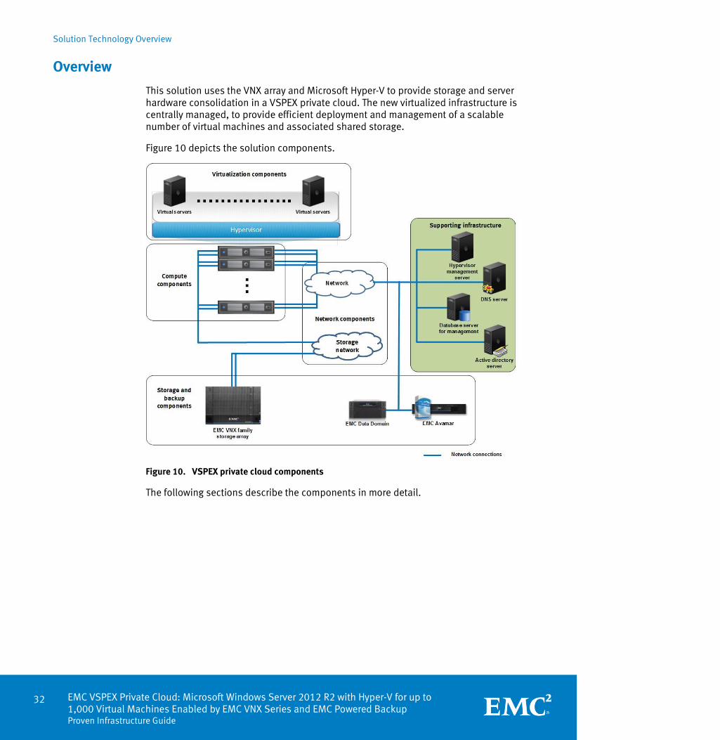
This solution uses the VNX array and Microsoft Hyper-V to provide storage and server hardware consolidation in a VSPEX private cloud. The new virtualized infrastructure is centrally managed, to provide efficient deployment and management of a scalable number of virtual machines and associated shared storage.
Figure 10 depicts the solution components.
Figure 10. VSPEX private cloud components
The following sections describe the components in more detail.
Solution Technology Overview
EMC VSPEX Private Cloud: Microsoft Windows Server 2012 R2 with Hyper-V for up to 1,000 Virtual Machines Enabled by EMC VNX Series and EMC Powered Backup
Proven Infrastructure Guide
33
Summary of key components
This section briefly describes the key components of this solution.
Virtualization
The virtualization layer decouples the physical implementation of resources from the applications that use them. The application’s view of the available resources is no longer directly tied to the hardware. This enables many key features in the private cloud concept.
Compute
The compute layer provides memory and processing resources for the virtualization layer software, and for the applications running in the private cloud. The VSPEX program defines the minimum amount of required compute layer resources, and enables the customer to implement the solution by using any server hardware that meets these requirements.
Network
The network layer connects the users of the private cloud to the resources in the cloud, and the storage layer to the compute layer. The VSPEX program defines the minimum number of required network ports, provides general guidance on network architecture, and enables the customer to implement the solution by using any network hardware that meets these requirements.
Storage
The storage layer is critical for the implementation of the private cloud. With multiple hosts accessing shared data, many of the use cases defined in the private cloud can be implemented. The VNX used in this solution provides high-performance data storage while maintaining high availability.
Backup and recovery
The backup and recovery components of the solution provide data protection when the data in the primary system is deleted, damaged, or unusable.
Solution architecture provides details on all the components that make up the reference architecture.

Solution Technology Overview
34 EMC VSPEX Private Cloud: Microsoft Windows Server 2012 R2 with Hyper-V for up to 1,000 Virtual Machines Enabled by EMC VNX Series and EMC Powered Backup Proven Infrastructure Guide
Virtualization
The virtualization layer is a key component of any server virtualization or private cloud solution. It decouples the application resource requirements from the underlying physical resources that serve them. This enables greater flexibility in the application layer by eliminating hardware downtime for maintenance, and allows the system to physically change without affecting the hosted applications. In a server virtualization or private cloud use case, it enables multiple independent virtual machines to share the same physical hardware, rather than being directly implemented on dedicated hardware.
Microsoft Hyper-V is a Windows Server role that was introduced in Windows Server 2008. Hyper-V virtualizes computer hardware resources, such as CPU, memory, storage, and networking. This transformation creates fully functional virtual machines that run their own operating systems and applications like physical computers.
Hyper-V works with Failover Clustering and Cluster Shared Volumes (CSVs) to provide high availability in a virtualized infrastructure. Live migration and live storage migration enable seamless movement of virtual machines or virtual machines files between Hyper-V servers or storage systems transparently and with mimimal performance impact.
Windows Server 2012 provides virtual Fibre Channel (FC) ports within a Hyper-V guest operating system. The virtual FC port uses the standard N-port ID virtualization (NPIV) process to address the virtual machine WWNs within the Hyper-V host’s physical host bus adapter (HBA). This provides virtual machines with direct access to external storage arrays over FC, enables clustering of guest operating systems over FC, and offers an important new storage option for the hosted servers in the virtual infrastructure. Virtual FC in Hyper-V guest operating systems also supports related features, such as virtual SANs, live migration, and multipath I/O (MPIO).
Prerequisites for virtual FC include:
One or more installations of Windows Server 2012 with the Hyper-V role
One or more FC HBAs installed on the server, each with an appropriate HBA driver that supports virtual FC
NPIV-enabled SAN
Virtual machines using the virtual FC adapter must use Windows Server 2008, Windows Server 2008 R2, or Windows Server 2012 as the guest operating system.
Microsoft System Center Virtual Machine Manager (SCVMM) is a centralized management platform for the virtualized data center. SCVMM allows administrators to configure and manage the virtualized host, networking, and storage resources, and to create and deploy virtual machines and services to private clouds. SCVMM simplifies provisioning, management, and monitoring in the Hyper-V environment.
Overview
Microsoft Hyper-V
Virtual Fibre Channel ports
Microsoft System Center Virtual Machine Manager

Solution Technology Overview
EMC VSPEX Private Cloud: Microsoft Windows Server 2012 R2 with Hyper-V for up to 1,000 Virtual Machines Enabled by EMC VNX Series and EMC Powered Backup
Proven Infrastructure Guide
35
The Windows Server 2012 Failover Clustering feature provides high-availability in Hyper-V. High availability is impacted by both planned and unplanned downtime, and Failover Clustering significantly increases the availability of virtual machines during planned and unplanned downtimes. Configure Windows Server 2012 Failover Clustering on the Hyper-V host to monitor virtual machine health, and migrate virtual machines between cluster nodes. The advantages of this configuration are:
Enables migration of virtual machines to a different cluster node if the cluster node where they reside must be updated, changed, or rebooted.
Allows other members of the Windows Failover Cluster to take ownership of the virtual machines if the cluster node where they reside suffers a failure or significant degradation.
Minimizes downtime due to virtual machine failures. Windows Server Failover Cluster detects virtual machine failures and automatically takes steps to recover the failed virtual machine. This allows the virtual machine to be restarted on the same host server, or migrated to a different host server.
Hyper-V Replica was introduced in Windows Server 2012 to provide asynchronous virtual machine replication over the network from one Hyper-V host at a primary site to another Hyper-V host at a replica site. Hyper-V replicas protect business applications in the Hyper-V environment from downtime associated with an outage at a single site.
Hyper-V Replica tracks the write operations on the primary virtual machine and replicates the changes to the replica server over the network with HTTP and HTTPS. The amount of network bandwidth required is based on the transfer schedule and data change rate.
If the primary Hyper-V host fails, you can manually fail over the production virtual machines to the Hyper-V hosts at the replica site. Manual failover brings the virtual machines back to a consistent point from which they can be accessed with minimal impact on the business. After recovery, the primary site can receive changes from the replica site. You can perform a planned failback to manually revert the virtual machines back to the Hyper-V host at the primary site.
High availability with Hyper-V Failover Clustering
Hyper-V Replica

Solution Technology Overview
36 EMC VSPEX Private Cloud: Microsoft Windows Server 2012 R2 with Hyper-V for up to 1,000 Virtual Machines Enabled by EMC VNX Series and EMC Powered Backup Proven Infrastructure Guide
A Hyper-V snapshot creates a consistent point-in-time view of a virtual machine. Snapshots function as source for backups or other use cases. Virtual machines do not have to be running to take a snapshot. Snapshots are completely transparent to the applications running on the virtual machine. The snapshot saves the point-in-time status of the virtual machine, and enables users to revert the virtual machine to a previous point-in-time if necessary.
Note: Snapshots require additional storage space. The amount of additional storage space depends on the frequency of data change on the virtual machine and the number of snapshots being retained.
Cluster-Aware Updating (CAU) was introduced in Windows Server 2012. It provides a way of updating cluster nodes with little or no disruption. CAU transparently performs the following tasks during the update process:
1. Puts one cluster node into maintenance mode and takes it offline (virtual machines are live-migrated to other cluster nodes).
2. Installs the updates.
3. Performs a restart if necessary.
4. Brings the node back online (migrated virtual machines are moved back to the original node).
5. Updates the next node in the cluster.
The node managing the update process is called the Orchestrator. The Orchestrator can work in a couple of different modes:
Self-updating mode: The Orchestrator runs on the cluster node being updated.
Remote-updating mode: The Orchestrator runs on a standalone Windows operating system, and remotely manages the cluster update.
CAU is integrated with Windows Server Update Service (WSUS). Powershell allows automation of the CAU process.
EMC Storage Integrator (ESI) is an agentless, free plug-in that enables application-aware storage provisioning for Microsoft Windows Server applications, Hyper-V, VMware, and Xen Server environments. Administrators can provision block and file storage for Microsoft Windows or Microsoft SharePoint sites by using wizards in ESI. ESI supports the following functions:
Provisioning, formatting, and presenting drives to Windows servers
Provisioning new cluster disks, and automatically adding them to the cluster
Provisioning shared CIFS storage, and mounting it to Windows servers
Provisioning SharePoint storage, sites, and databases in a single wizard
Hyper-V snapshot
Cluster-Aware Updating
EMC Storage Integrator

Solution Technology Overview
EMC VSPEX Private Cloud: Microsoft Windows Server 2012 R2 with Hyper-V for up to 1,000 Virtual Machines Enabled by EMC VNX Series and EMC Powered Backup
Proven Infrastructure Guide
37
Compute
The choice of a server platform for an VSPEX infrastructure is not only based on the technical requirements of the environment, but on the supportability of the platform, existing relationships with the server provider, advanced performance, management features, and many other factors. For this reason, VSPEX solutions are designed to run on a wide variety of server platforms. Instead of requiring a specific number of servers with a specific set of requirements, VSPEX documents the minimum requirements for the number of processor cores, and the amount of RAM. This can be implemented with two or twenty servers, and still be considered the same VSPEX solution.
In the example shown in Figure 11, the compute layer requirements for a specific implementation are 25 processor cores and 200 GB of RAM. One customer might want to implement this by using white-box servers containing 16 processor cores, and 64 GB of RAM, while another customer chooses a higher-end server with 20 processor cores and 144 GB of RAM.
Figure 11. Compute layer flexibility
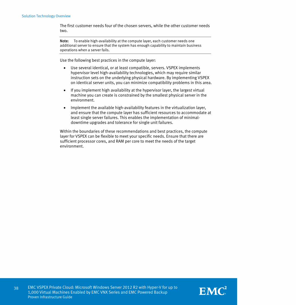
Solution Technology Overview
38 EMC VSPEX Private Cloud: Microsoft Windows Server 2012 R2 with Hyper-V for up to 1,000 Virtual Machines Enabled by EMC VNX Series and EMC Powered Backup Proven Infrastructure Guide
The first customer needs four of the chosen servers, while the other customer needs two.
Note: To enable high-availability at the compute layer, each customer needs one additional server to ensure that the system has enough capability to maintain business operations when a server fails.
Use the following best practices in the compute layer:
Use several identical, or at least compatible, servers. VSPEX implements hypervisor level high-availability technologies, which may require similar instruction sets on the underlying physical hardware. By implementing VSPEX on identical server units, you can minimize compatibility problems in this area.
If you implement high availability at the hypervisor layer, the largest virtual machine you can create is constrained by the smallest physical server in the environment.
Implement the available high-availability features in the virtualization layer, and ensure that the compute layer has sufficient resources to accommodate at least single server failures. This enables the implementation of minimal-downtime upgrades and tolerance for single unit failures.
Within the boundaries of these recommendations and best practices, the compute layer for VSPEX can be flexible to meet your specific needs. Ensure that there are sufficient processor cores, and RAM per core to meet the needs of the target environment.
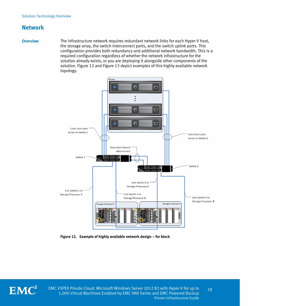
Solution Technology Overview
EMC VSPEX Private Cloud: Microsoft Windows Server 2012 R2 with Hyper-V for up to 1,000 Virtual Machines Enabled by EMC VNX Series and EMC Powered Backup
Proven Infrastructure Guide
39
Network
The infrastructure network requires redundant network links for each Hyper-V host, the storage array, the switch interconnect ports, and the switch uplink ports. This configuration provides both redundancy and additional network bandwidth. This is a required configuration regardless of whether the network infrastructure for the solution already exists, or you are deploying it alongside other components of the solution. Figure 12 and Figure 13 depict examples of this highly available network topology.
Figure 12. Example of highly available network design – for block
Overview

Solution Technology Overview
40 EMC VSPEX Private Cloud: Microsoft Windows Server 2012 R2 with Hyper-V for up to 1,000 Virtual Machines Enabled by EMC VNX Series and EMC Powered Backup Proven Infrastructure Guide
Figure 13. Example of highly available network design – for file
This validated solution uses virtual local area networks (VLANs) to segregate network traffic of various types to improve throughput, manageability, application separation, high availability, and security.
For block, EMC unified storage platforms provide network high availability or redundancy by two ports per storage processor. If a link is lost on the storage processor front end port, the link fails over to another port. All network traffic is distributed across the active links.
For file, the EMC unified storage platforms provide network high availability or redundancy by using link aggregation. Link aggregation enables multiple active (MAC) Ethernet connections to appear as a single link with a single MAC address, and potentially multiple IP addresses. In this solution, Link Aggregation Control Protocol (LACP) is configured on the VNX array, combining multiple Ethernet ports into a single virtual device. If a link is lost on the Ethernet port, the link fails over to another port. All network traffic is distributed across the active links.

Solution Technology Overview
EMC VSPEX Private Cloud: Microsoft Windows Server 2012 R2 with Hyper-V for up to 1,000 Virtual Machines Enabled by EMC VNX Series and EMC Powered Backup
Proven Infrastructure Guide
41
Storage
The storage layer is also a key component of any cloud infrastructure solution that serves data generated by applications and operating systems in data center storage processing systems. This increases storage efficiency, management flexibility, and reduces total cost of ownership. In this VSPEX solution, EMC VNX series arrays provide features and performance to enable and enhance any virtualization environment.
The EMC VNX family is optimized for virtual applications; and delivers innovation and enterprise capabilities for file and block storage in a scalable, easy-to-use solution. This next-generation storage platform combines powerful and flexible hardware with advanced efficiency, management, and protection software to meet the demanding needs of today’s enterprises.
Intel Xeon processors power the VNX series for intelligent storage that automatically and efficiently scales in performance, while ensuring data integrity and security. It is designed to meet the high performance, high-scalability requirements of midsize and large enterprises.
Table 1 shows the customer benefits that are provided by the VNX series.
Table 1. VNX customer benefits
Feature Benefit
Next-generation unified storage, optimized for virtualized applications
Tight integration with Microsoft Windows Server 2012 R2 and Microsoft System Center 2012 R2 allows for advanced array features and centralized management
Capacity optimization features including compression, deduplication, thin provisioning, and application-consistent copies
Reduced storage costs, more efficient use of resources and easier recovery of applications
High-availability, designed to deliver five 9s availability
Higher levels of uptime and reduced outage risk
Automated tiering with FAST VP and FAST Cache that can be optimized for the highest system performance and lowest storage cost simultaneously
More efficient use of storage resources without complicated planning and configuration
Simplified management with EMC Unisphere for a single management interface for all NAS, SAN and replication needs
Reduced management overhead and toolsets required to manage environment
Up to three times improvement in performance with the latest Intel Xeon multicore processor technology, optimized for flash
Reduced latency, increased bandwidth and IOPS result in more headroom for demanding workloads
Overview
EMC VNX series

Solution Technology Overview
42 EMC VSPEX Private Cloud: Microsoft Windows Server 2012 R2 with Hyper-V for up to 1,000 Virtual Machines Enabled by EMC VNX Series and EMC Powered Backup Proven Infrastructure Guide
Different software suites and packs are also available for the VNX series, which provide multiple features for enhanced protection and performance.
Software suites
The following VNX software suites are available:
FAST Suite — Automatically optimizes for the highest system performance and the lowest storage cost simultaneously.
Local Protection Suite — Practices safe data protection and repurposing.
Remote Protection Suite — Protects data against localized failures, outages, and disasters.
Application Protection Suite — Automates application copies and provides compliance.
Security and Compliance Suite — Keeps data safe from changes, deletions, and malicious activity.
Software packs
The following VNX software packs are available:
Total Efficiency Pack — Includes all five software suites.
Total Protection Pack — Includes local, remote, and application protection suites.
VNX Snapshots is a software feature that creates point-in-time data copies. VNX Snapshots can be used for data backups, software development and testing, repurposing, data validation, and local rapid restores. VNX Snapshots improves on the existing ENC VNX SnapView™ snapshot functionality by integrating with storage pools.
Note: LUNs created on physical RAID groups, also called RAID LUNs, support only SnapView snapshots. This limitation exists because VNX Snapshots requires pool space as part of its technology.
VNX Snapshots supports 256 writeable snapshots per pool LUN. It supports branching, also called ‘Snap of a Snap’, as long as the total number of snapshots for any primary LUN is less than 256, which is a hard limit.
VNX Snapshots uses redirect on write (ROW) technology. ROW redirects new writes destined for the primary LUN to a new location in the storage pool. Such an implementation is different from copy on first write (COFW) used in SnapView, which holds the writes to the primary LUN until the original data is copied to the reserved LUN pool to preserve a snapshot.
This release also supports consistency groups (CGs). Several pool LUNs can be combined into a CG and snapped concurrently. When a snapshot of a CG is initiated, all writes to the member LUNs are held until snapshots have been created. Typically, CGs are used for LUNs that belong to the same application.
EMC VNX Snapshots

Solution Technology Overview
EMC VSPEX Private Cloud: Microsoft Windows Server 2012 R2 with Hyper-V for up to 1,000 Virtual Machines Enabled by EMC VNX Series and EMC Powered Backup
Proven Infrastructure Guide
43
EMC VNX SnapSure™ is an EMC VNX File software feature that enables you to create and manage checkpoints that are point-in-time, logical images of a production file system (PFS). SnapSure uses a copy-on-first-modify principle. A PFS consists of blocks. When a block within the PFS is modified, a copy containing the block’s original contents is saved to a separate volume called the SavVol.
Subsequent changes made to the same block in the PFS are not copied into the SavVol. The original blocks from the PFS in the SavVol and the unchanged PFS blocks remaining in the PFS are read by SnapSure according to a bitmap and block map data-tracking structure. These blocks combine to provide a complete point-in-time image called a checkpoint.
A checkpoint reflects the state of a PFS at the time the checkpoint was created. SnapSure supports these types of checkpoints:
Read-only checkpoints — Read-only file systems created from a PFS
Writeable checkpoints — Read/write file systems created from a read-only checkpoint
SnapSure can maintain a maximum of 96 read-only checkpoints and 16 writeable checkpoints per PFS, while allowing PFS applications continued access to real-time data.
Note: Each writeable checkpoint associates with a read-only checkpoint, referred to as the baseline checkpoint. Each baseline checkpoint can have only one associated writeable checkpoint.
For more detailed information, refer to the document Using VNX SnapSure.
EMC VNX Virtual Provisioning™ enables organizations to reduce storage costs by increasing capacity utilization, simplifying storage management, and reducing application downtime. Virtual Provisioning also helps companies to reduce power and cooling requirements and reduce capital expenditures.
Virtual Provisioning provides pool-based storage provisioning by implementing pool LUNs that can be either thin or thick. Thin LUNs provide on-demand storage that maximizes the utilization of your storage by allocating storage only as needed. Thick LUNs provide both high performance and predictable performance for your applications. Both types of LUNs benefit from the ease-of-use features of pool-based provisioning.
Pools and pool LUNs are also the building blocks for advanced data services such as FAST VP, VNX Snapshots, and compression. Pool LUNs also support a variety of additional features, such as LUN shrink, online expansion, and User Capacity Threshold setting.
EMC VNX Virtual Provisioning allows you to expand the capacity of a storage pool from the Unisphere GUI after disks are physically attached to the system. VNX systems have the ability to rebalance allocated data elements across all member drives to use new drives after the pool is expanded. The rebalance function starts automatically and runs in the background after an expand action. You can monitor
EMC VNX SnapSure
EMC VNX Virtual Provisioning

Solution Technology Overview
44 EMC VSPEX Private Cloud: Microsoft Windows Server 2012 R2 with Hyper-V for up to 1,000 Virtual Machines Enabled by EMC VNX Series and EMC Powered Backup Proven Infrastructure Guide
the progress of a rebalance operation from the General tab of the Pool Properties window in Unisphere, as shown in Figure 14.
Figure 14. Storage pool rebalance progress
LUN expansion
Use pool LUN expansion to increase the capacity of existing LUNs. It allows for provisioning larger capacity as business needs grow.
The VNX family has the capability to expand a pool LUN without disrupting user access. You can expand pool LUNs with a few simple clicks and the expanded capacity is immediately available. However, you cannot expand a pool LUN if it is part of a data-protection or LUN-migration operation. For example, snapshot LUNs or migrating LUNs cannot be expanded.
LUN shrink
Use LUN shrink to reduce the capacity of existing thin LUNs.
VNX can shrink a pool LUN. This capability is only available for LUNs served by Windows Server 2008 and later. The shrinking process involves these steps:
1. Shrink the file system from Windows Disk Management.
2. Shrink the pool LUN using a command window and the DISKRAID utility. The utility is available through the VDS Provider, which is part of the EMC Solutions Enabler package.
The new LUN size appears as soon as the shrink process is complete. A background task reclaims the deleted or shrunk space and returns it to the storage pool. Once the task is complete, any other LUN in that pool can use the reclaimed space.
For more detailed information on LUN expansion/shrinkage, refer to EMC VNX Virtual Provisioning — Applied Technology White Paper.

Solution Technology Overview
EMC VSPEX Private Cloud: Microsoft Windows Server 2012 R2 with Hyper-V for up to 1,000 Virtual Machines Enabled by EMC VNX Series and EMC Powered Backup
Proven Infrastructure Guide
45
Alerting the user through the Capacity Threshold setting
You must configure proactive alerts when using a file system or storage pools based on thin pools. Monitor these resources so that storage is available for provisioning when needed and capacity shortages can be avoided.
Figure 15 explains why provisioning with thin pools requires monitoring.
Figure 15. Thin LUN space utilization
Monitor the following values for thin pool utilization:
Total capacity is the total physical capacity available to all LUNs in the pool.
Total allocation is the total physical capacity currently assigned to all pool LUNs.
Subscribed capacity is the total host-reported capacity supported by the pool.
Over-subscribed capacity is the amount of user capacity configured for LUNs that exceeds the physical capacity in a pool.
Total allocation must never exceed the total capacity, but if it nears that point, add storage to the pools proactively before reaching a hard limit.
Figure 16 shows the Storage Pool Properties dialog box in Unisphere, which displays parameters such as Free, Percent Full, Total Allocation, Total Subscription of physical capacity, Percent Subscribed and Oversubscribed By of virtual capacity.

Solution Technology Overview
46 EMC VSPEX Private Cloud: Microsoft Windows Server 2012 R2 with Hyper-V for up to 1,000 Virtual Machines Enabled by EMC VNX Series and EMC Powered Backup Proven Infrastructure Guide
Figure 16. Examining storage pool space utilization
When storage pool capacity becomes exhausted, any requests for additional space allocation on thin-provisioned LUNs fail. Applications attempting to write data to these LUNs usually fail as well, and an outage is the likely result. To avoid this situation, monitor pool utilization, and be alerted when thresholds are reached, set the Percentage Full Threshold to allow enough buffer to correct the situation before an outage situation occurs. Edit this setting by selecting Advanced in the Storage Pool Properties dialog box, as seen in Figure 17. This alert is only active if there are one or more thin LUNs in the pool, because thin LUNs are the only way to oversubscribe a pool. If the pool only contains thick LUNs, the alert is not active because there is no risk of running out of space due to oversubscription. You also can specify the value for Percent Full Threshold, which equals Total Allocation/Total Capacity, when a pool is created.

Solution Technology Overview
EMC VSPEX Private Cloud: Microsoft Windows Server 2012 R2 with Hyper-V for up to 1,000 Virtual Machines Enabled by EMC VNX Series and EMC Powered Backup
Proven Infrastructure Guide
47
Figure 17. Defining storage pool utilization thresholds
View alerts by Alert in Unisphere. Figure 18 shows the Unisphere Event Monitor wizard, where you can also select the option of receiving alerts through email, a paging service, or an SNMP trap.
Figure 18. Defining automated notifications - for block
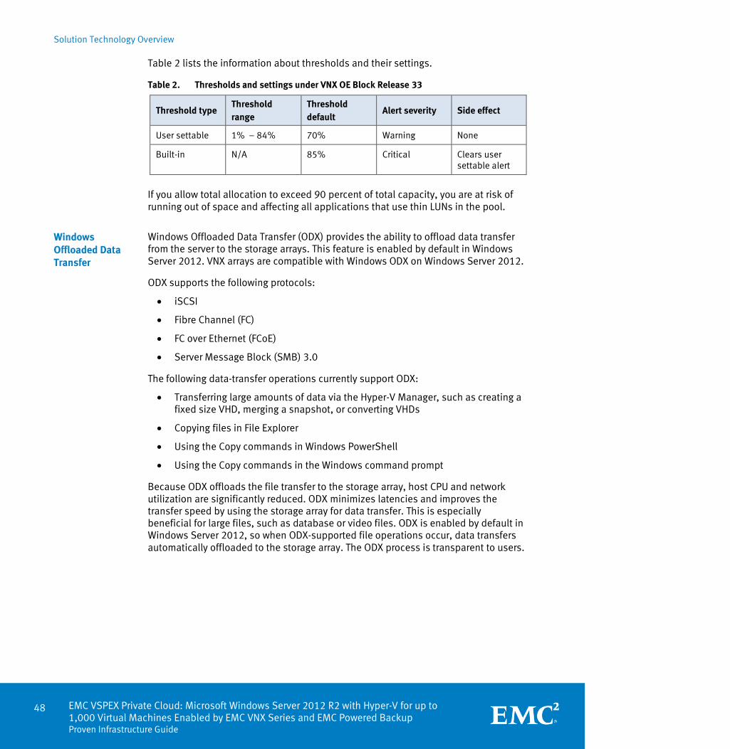
Solution Technology Overview
48 EMC VSPEX Private Cloud: Microsoft Windows Server 2012 R2 with Hyper-V for up to 1,000 Virtual Machines Enabled by EMC VNX Series and EMC Powered Backup Proven Infrastructure Guide
Table 2 lists the information about thresholds and their settings.
Table 2. Thresholds and settings under VNX OE Block Release 33
Threshold type Threshold range
Threshold default
Alert severity Side effect
User settable 1% – 84% 70% Warning None
Built-in N/A 85% Critical Clears user settable alert
If you allow total allocation to exceed 90 percent of total capacity, you are at risk of running out of space and affecting all applications that use thin LUNs in the pool.
Windows Offloaded Data Transfer (ODX) provides the ability to offload data transfer from the server to the storage arrays. This feature is enabled by default in Windows Server 2012. VNX arrays are compatible with Windows ODX on Windows Server 2012.
ODX supports the following protocols:
iSCSI
Fibre Channel (FC)
FC over Ethernet (FCoE)
Server Message Block (SMB) 3.0
The following data-transfer operations currently support ODX:
Transferring large amounts of data via the Hyper-V Manager, such as creating a fixed size VHD, merging a snapshot, or converting VHDs
Copying files in File Explorer
Using the Copy commands in Windows PowerShell
Using the Copy commands in the Windows command prompt
Because ODX offloads the file transfer to the storage array, host CPU and network utilization are significantly reduced. ODX minimizes latencies and improves the transfer speed by using the storage array for data transfer. This is especially beneficial for large files, such as database or video files. ODX is enabled by default in Windows Server 2012, so when ODX-supported file operations occur, data transfers automatically offloaded to the storage array. The ODX process is transparent to users.
Windows Offloaded Data Transfer

Solution Technology Overview
EMC VSPEX Private Cloud: Microsoft Windows Server 2012 R2 with Hyper-V for up to 1,000 Virtual Machines Enabled by EMC VNX Series and EMC Powered Backup
Proven Infrastructure Guide
49
EMC PowerPath® is a host-based software package that provides automated data path management and load-balancing capabilities for heterogeneous server, network, and storage deployed in physical and virtual environments. It offers the following benefits for the VSPEX Proven Infrastructure:
Standardized data management across physical and virtual environments.
Automated multipathing policies and load balancing to provide predictable and consistent application availability and performance across physical and virtual environments.
Improved service-level agreements by eliminating application impact from I/O failures.
EMC FAST Cache, a part of the EMC FAST Suite, enables flash drives to function as an expanded cache layer for the array. FAST Cache is an array-wide, nondisruptive cache, available for both file and block storage. Frequently accessed data is copied to the FAST Cache in 64 KB increments and subsequent reads and/or writes to the data chunk are serviced by FAST Cache. This enables immediate promotion of highly active data to flash drives. This dramatically improves the response time for the active data and reduces data hot spots that can occur within a LUN. The FAST Cache feature is an optional component of this solution.
In many environments it is important to have a common location to store files accessed by many different individuals. This is implemented as CIFS or NFS file shares from a file server. VNX storage arrays can provide this service along with centralized management, client integration, advanced security options, and efficiency improvement features. For more information, refer to the document Configuring and Managing CIFS on VNX.
Organizations with remote office and branch offices (ROBO) often prefer to locate data and applications close to the users in order to provide better performance and lower latency. In these environments, IT departments need to balance the benefits of local support with the need to maintain central control. Local Systems and storage should be easy for local personnel to administer, but also support remote management and flexible aggregation tools that minimize the demands on those local resources. With VSPEX, you can accelerate the deployment of applications at remote offices and branch offices. Customers can also leverage Unisphere Remote to consolidate the monitoring, system alerts, and reporting of hundreds of locations while maintaining simplicity of operation and unified storage functionality for local managers.
BranchCache is a feature that allows clients to cache data stored on SMB 3.0 shares locally at the branch office. With BranchCache capability, remote users that access file shares can cache files locally, which helps future lookups, reduces network traffic, and improves scalability and performance.
For more information on BranchCache, refer to SMB 3.0 features.
EMC PowerPath
EMC FAST Cache
VNX file shares
ROBO

Solution Technology Overview
50 EMC VSPEX Private Cloud: Microsoft Windows Server 2012 R2 with Hyper-V for up to 1,000 Virtual Machines Enabled by EMC VNX Series and EMC Powered Backup Proven Infrastructure Guide
SMB 3.0 features
SMB 3.0 supports Hyper-V and Microsoft SQL Server storage. Microsoft also introduced several key features that improve the performance of these applications, and simplify application management tasks.
This section describes SMB 3.0 features supported on VNX storage arrays, and indicates how these features affect the performance of applications or data stored on SMB 3.0 file shares.
For more information, refer to the EMC VNX Series: Introduction to SMB 3.0 Support White Paper.
The SMB protocol follows the client-server model. The protocol level is negotiated by client request and server response when establishing a new SMB connection.
The SMB versions for various Windows operating systems are as follows:
CIFS – Windows NT 4.0
SMB 1.0 – Windows 2000, Windows XP, Windows Server 2003, and Windows Server 2003 R2
SMB 2.0 – Windows Vista (SP1 or later) and Windows Server 2008
SMB 2.1 – Windows 7 and Windows Server 2008 R2
SMB 3.0 – Windows 8 and Windows Server 2012
Before establishing a session between the client and server, a common SMB dialect is negotiated. Table 3 shows the common dialect used based on the SMB versions supported by the client and server.
Table 3. SMB dialect used between client and server
Client-server SMB 3.0 SMB 2.1 SMB 2.0
SMB 3.0 SMB 3.0 SMB 2.1 SMB 2.0
SMB 2.1 SMB 2.1 SMB 2.1 SMB 2.0
SMB 2.0 SMB 2.0 SMB 2.0 SMB 2.0
SMB 1.0 SMB 1.0 SMB 1.0 SMB 1.0
For more information on SMB versions and negotiations, refer to the Microsoft TechNet technical document entitled Server Message Block (SMB) Protocol Versions 2 and 3.
All features mentioned in this document are supported in the latest releases of VNX operating environment (OE) for File and VNXe OE.
Overview
SMB versions and negotiations
VNX and VNXe storage support
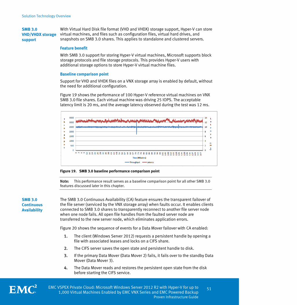
Solution Technology Overview
EMC VSPEX Private Cloud: Microsoft Windows Server 2012 R2 with Hyper-V for up to 1,000 Virtual Machines Enabled by EMC VNX Series and EMC Powered Backup
Proven Infrastructure Guide
51
With Virtual Hard Disk file format (VHD and VHDX) storage support, Hyper-V can store virtual machines, and files such as configuration files, virtual hard drives, and snapshots on SMB 3.0 shares. This applies to standalone and clustered servers.
Feature benefit
With SMB 3.0 support for storing Hyper-V virtual machines, Microsoft supports block storage protocols and file storage protocols. This provides Hyper-V users with additional storage options to store Hyper-V virtual machine files.
Baseline comparison point
Support for VHD and VHDX files on a VNX storage array is enabled by default, without the need for additional configuration.
Figure 19 shows the performance of 100 Hyper-V reference virtual machines on VNX SMB 3.0 file shares. Each virtual machine was driving 25 IOPS. The acceptable latency limit is 20 ms, and the average latency observed during the test was 12 ms.
Figure 19. SMB 3.0 baseline performance comparison point
Note: This performance result serves as a baseline comparison point for all other SMB 3.0 features discussed later in this chapter.
The SMB 3.0 Continuous Availability (CA) feature ensures the transparent failover of the file server (serviced by the VNX storage array) when faults occur. It enables clients connected to SMB 3.0 shares to transparently reconnect to another file server node when one node fails. All open file handles from the faulted server node are transferred to the new server node, which eliminates application errors.
Figure 20 shows the sequence of events for a Data Mover failover with CA enabled: 1. The client (Windows Server 2012) requests a persistent handle by opening a
file with associated leases and locks on a CIFS share.
2. The CIFS server saves the open state and persistent handle to disk.
3. If the primary Data Mover (Data Mover 2) fails, it fails over to the standby Data Mover (Data Mover 3).
4. The Data Mover reads and restores the persistent open state from the disk before starting the CIFS service.
SMB 3.0 VHD/VHDX storage support
SMB 3.0 Continuous Availability

Solution Technology Overview
52 EMC VSPEX Private Cloud: Microsoft Windows Server 2012 R2 with Hyper-V for up to 1,000 Virtual Machines Enabled by EMC VNX Series and EMC Powered Backup Proven Infrastructure Guide
5. Using the persistent handle, the client re-establishes the connection to the same CIFS server, and recovers the same context associated with the open file as before the failover occurred.
Figure 20. SMB 3.0 Continuous Availability
Feature benefit
When a Data Mover fails, clients accessing SMB 3.0 shares created with CA do not perceive any application errors. Instead, they experience a small I/O delay due to the primary Data Mover failing over to the standby Data Mover. After the failover, the application may experience a brief spike in latency but soon resumes normal operation.
Enabling the feature
This feature is required for Hyper-V environments. To enable this feature, run the following commands from the VNX Control Station.
1. To mount the file system through which the share will be exported with the
smbca option:
server_mount <server_name> -o smbca <fsname> /<fsmountpoint>
2. To export the share with the CA option:
server_export <server_name> -P cifs –n <sharename> –o
type=CA /<fsmountpoint>

Solution Technology Overview
EMC VSPEX Private Cloud: Microsoft Windows Server 2012 R2 with Hyper-V for up to 1,000 Virtual Machines Enabled by EMC VNX Series and EMC Powered Backup
Proven Infrastructure Guide
53
Performance impact
This feature does not impact storage, server, or network performance. The only time that performance changes is after a failover or failback operation, when there is a spike in IOPS and latency for a brief period before normal operation resumes.
Figure 21 shows the performance of VDbench on host when the primary Data Mover panics. There is an I/O delay during the failover operation. When the failover completes, the standby is active, and the VDbench returns to normal operation after a short spike in I/O and latency.
Figure 21. CA – application performance
The SMB Multichannel feature utilizes multiple network interfaces and connections to provide higher throughput and fault tolerance. This is achieved without any additional configuration steps for the network interfaces.
Feature benefits
SMB Multichannel provides network high-availability. If one of the network interface cards (NICs) fails, the applications and clients continue operating at a lower throughput potential without any errors. SMB Multichannel is automatically configured. All network paths are automatically detected, and connections are added dynamically.
SMB Multichannel works as follows:
Multichannel connections on a single NIC for improved throughput:
SMB Multichannel does not provide any additional throughput if the single NIC does not support RSS Receive Side Scaling (RSS). RSS allows multiple connections to spread across the CPU cores automatically and hence can distribute load between the CPU cores by creating multiple TCP/IP connections.
Multichannel connections on multiple NICs for improved throughput:
SMB Multichannel

Solution Technology Overview
54 EMC VSPEX Private Cloud: Microsoft Windows Server 2012 R2 with Hyper-V for up to 1,000 Virtual Machines Enabled by EMC VNX Series and EMC Powered Backup Proven Infrastructure Guide
SMB Multichannel creates multiple TCP/IP sessions – one for each available interface. If the NICs are RSS-capable, many TCP/IP connections per NIC are created.
Enabling the feature
SMB Multichannel is enabled by default on the VNX storage array. No parameter needs to be set on the system to use this feature. This feature is also enabled by default on Windows 8 and Windows 2012 clients.
Performance impact
SMB Multichannel provides additional network throughput by creating more TCP/IP connections (at least one per NIC). If the network is underutilized, no performance degradation is observed when one NIC fails. However, if the network is being heavily utilized, the application continues functioning at a lower throughput.
Figure 22 shows the network-resiliency test result on an SMB 3.0 client when one out of two NICs is disabled. The application does not experience any errors or faults, and continues to perform normally even when the interface is enabled again.
Figure 22. SMB Multichannel fault tolerance
The application does not have an impact on performance because the network was not the bottleneck during the test. If it were a bottleneck, the response time would have been higher. However, the application would have continued functioning without any errors if the higher response time was acceptable.
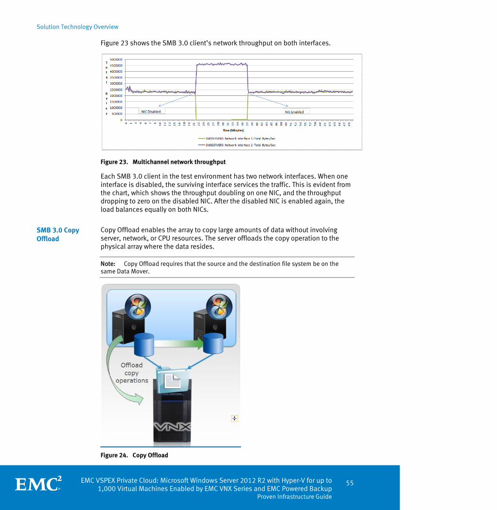
Solution Technology Overview
EMC VSPEX Private Cloud: Microsoft Windows Server 2012 R2 with Hyper-V for up to 1,000 Virtual Machines Enabled by EMC VNX Series and EMC Powered Backup
Proven Infrastructure Guide
55
Figure 23 shows the SMB 3.0 client’s network throughput on both interfaces.
Figure 23. Multichannel network throughput
Each SMB 3.0 client in the test environment has two network interfaces. When one interface is disabled, the surviving interface services the traffic. This is evident from the chart, which shows the throughput doubling on one NIC, and the throughput dropping to zero on the disabled NIC. After the disabled NIC is enabled again, the load balances equally on both NICs.
Copy Offload enables the array to copy large amounts of data without involving server, network, or CPU resources. The server offloads the copy operation to the physical array where the data resides.
Note: Copy Offload requires that the source and the destination file system be on the same Data Mover.
Figure 24. Copy Offload
SMB 3.0 Copy Offload

Solution Technology Overview
56 EMC VSPEX Private Cloud: Microsoft Windows Server 2012 R2 with Hyper-V for up to 1,000 Virtual Machines Enabled by EMC VNX Series and EMC Powered Backup Proven Infrastructure Guide
Feature benefits
Copy Offload enables faster data transfer from source to destination because it does not use any client CPU cycles. This feature is most beneficial for the following operations:
Deployment operations:
Deploy multiple virtual machines faster. The baseline VHDX can reside on an SMB 3.0 share, with new virtual machines deployed on SMB 3.0 shares with Hyper-V Manager, by pointing to the baseline VHDX.
Cloning operations:
Clone virtual machines from one SMB 3.0 share to another in minutes.
Migration operations:
Migrate virtual machines between file shares on the same Data Mover in 10 minutes, as opposed to almost 40 minutes without the Copy Offload feature.
Table 4 shows the time taken to move virtual machine storage with and without the Copy Offload feature.
Table 4. Storage migration improvement with Copy Offload
Number of virtual machines (100 GB each)
Time spent for storage migration with Copy Offload enabled
Time spent for storage migration with Copy Offload disabled
1 10 mins 37 mins
2 13 mins 82 mins
5 26 mins More than 4 hours
10 50 mins More than 8 hours
Enabling the feature
This feature is enabled by default on the VNX storage array, Windows 8, and Windows Server 2012 clients.
Performance impact
Because the array handles the entire copy operation, the Copy Offload feature increases the utilization of the Data Mover CPU and other array resources. The performance of the feature is limited by the array read/write bandwidth.
BranchCache enables clients to cache data stored on SMB 3.0 shares locally at the branch office. The cached content is encrypted between peers, clients, and hosted cache servers. This feature was first introduced with Windows 7 and Windows 2008 R2. SMB 3.0 supports BranchCache v2.
Implement BranchCache in one of two modes:
Distributed cache mode: Distributes cache between the client computers at the branch office.
SMB 3.0 BranchCache

Solution Technology Overview
EMC VSPEX Private Cloud: Microsoft Windows Server 2012 R2 with Hyper-V for up to 1,000 Virtual Machines Enabled by EMC VNX Series and EMC Powered Backup
Proven Infrastructure Guide
57
Hosted cache mode: Maintains cached content on a separate computer at the branch office.
For more information on BranchCache, refer to the Microsoft TechNet Library topic Branch Cache Overview.
Feature benefit
With BranchCache capability, remote users who access file shares can cache files locally at the branch office. This helps future lookups, reduces network traffic, and improves scalability and performance.
Enabling the feature
TheBranchCache feature is not enabled by default on the VNX storage array. Run the following command on the VNX Control Station to enable BranchCache:
server_cifs <server_name> smbhash –service –enable
To create the share with type=HASH, run the following command:
server_export <server_name> -o type=HASH
On a DC of a Windows Server 2012 domain where the VNX is connected, edit the default domain policy as follows to activate:
Computer Configuration\Policies\Administrative
Templates\Network\Lanman Server\Hash Publication for BranchCache.
Performance impact
This feature reduces network traffic, as the cached data is available locally at the branch office. Client performance also improves due to faster access to data, but there is some overhead involved to encrypt and decrypt data between BranchCache members.
Remote VSS (RVSS) is a Remote Procedure Call (RPC) based protocol, which enables application-consistent shadow copies of VSS-aware server applications. RVSS stores data on SMB 3.0 file shares.
RVSS supports application backup across multiple file servers and shares. VSS-aware backup applications can perform snapshots of server applications that store data on the VNX CIFS shares. Hyper-V has the ability to store virtual machine files on CIFS shares, and RVSS can take point-in-time copies of the share contents.
Some examples of shadow copy uses are:
Creating backups
Recovering data
Testing scenarios
Mining data
SMB 3.0 Remote VSS

Solution Technology Overview
58 EMC VSPEX Private Cloud: Microsoft Windows Server 2012 R2 with Hyper-V for up to 1,000 Virtual Machines Enabled by EMC VNX Series and EMC Powered Backup Proven Infrastructure Guide
Feature benefit
RVSS uses the existing Microsoft VSS infrastructure to integrate with VSS-aware backup software and applications. Backup applications read directly from shadow-copy file shares instead of involving the server application computer.
Enabling the feature
RVSS is enabled by default on the VNX storage array, without a need for additional configuration.
Performance impact
RVSS increases the load on the VNX storage array because it takes application-consistent copies (or snapshots) of applications running on the file shares.
SMB 3.0 allows in-flight, end-to-end encryption of data, and protects it on untrusted networks. Enable this feature for an individual share, or for the entire CIFS server node. This feature only works with SMB 3.0 clients. If the share is encrypted, deny access, or allow unencrypted access for non-SMB 3.0 clients.
Feature benefit
SMB encryption does not require any additional software or hardware. It protects data on the network from attacks and eavesdropping.
Enabling the feature
This feature is not enabled by default on the VNX storage array.
Enabling encryption on all shares
To configure encryption on all shares, set the Encrypt Data parameter in the VNX CIFS server registry to 0x1.To configure this parameter, complete the following steps:
1. Open the Registry Editor (regedit.exe) on a computer.
2. Select File > Connect Network Registry.
3. Enter the hostname or IP address of the CIFS server, and click Check Names.
4. When the server is recognized, click OK to close the window.
5. Edit the Encrypt Data parameter (0x1 is enabled, and 0x0 is disabled)under HKEY\System\CurrentControlSet\Services\LanmanServer\Parameters as shown in Figure 25.
SMB 3.0 encryption

Solution Technology Overview
EMC VSPEX Private Cloud: Microsoft Windows Server 2012 R2 with Hyper-V for up to 1,000 Virtual Machines Enabled by EMC VNX Series and EMC Powered Backup
Proven Infrastructure Guide
59
Figure 25. Enabling the Encrypt Data parameter
By default only SMB 3.0 clients can access encrypted VNX file shares. In order to allow pre-SMB 3.0 clients to access encrypted shares, the RejectUnencryptedAccess value under the VNX CIFS server registry location shown in Figure 16 must be set to 0x0.
Enabling encryption on a specific share
To enable encryption for a particular share, run the following command on the VNX Control Station:
server_export <server_name> -P cifs –n <sharename> –o
type=Encrypted /<fsmountpoint>
Performance impact
With encryption enabled on the shares, Data Mover CPU, and SMB 3.0 client utilization increases because encryption and decryption require additional overhead.
Figure 26 shows an increase in CPU utilization with encryption enabled on the SMB 3.0 shares.
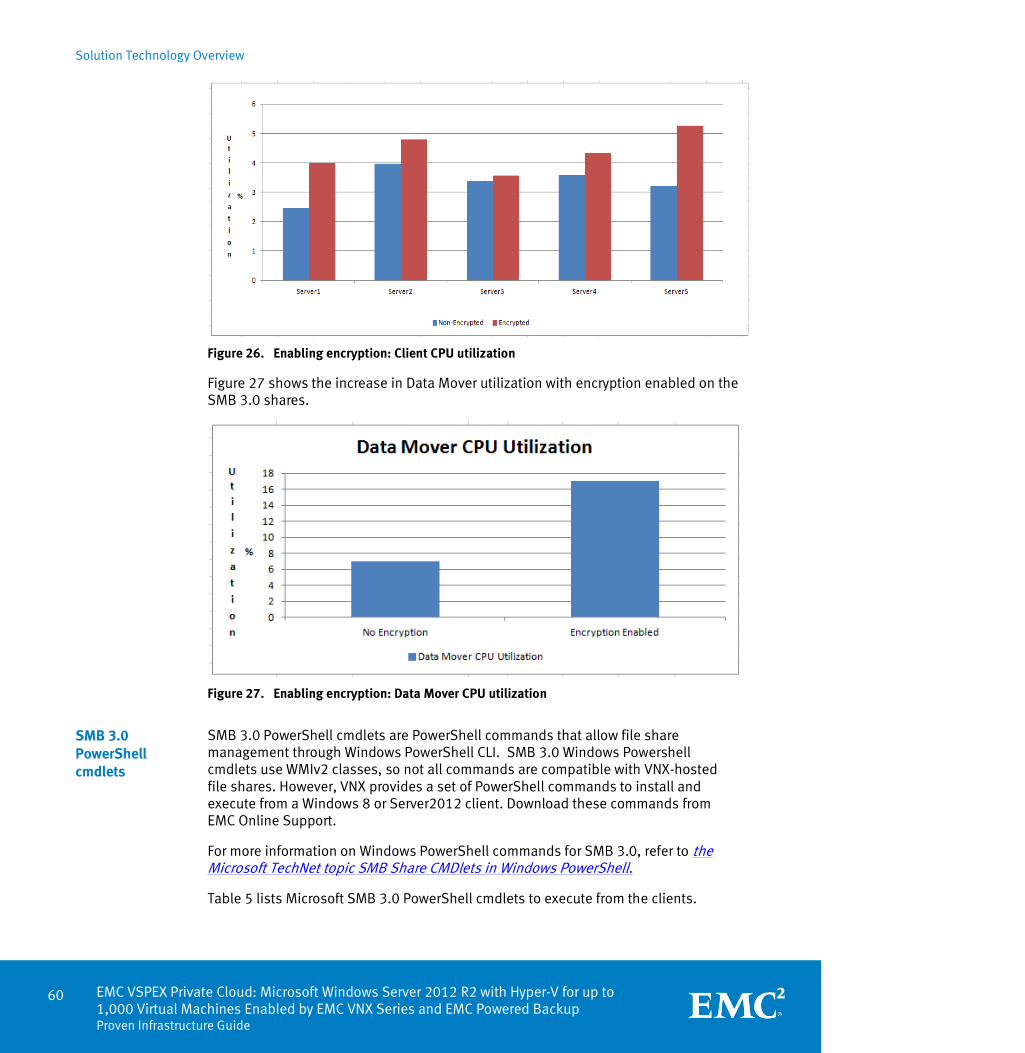
Solution Technology Overview
60 EMC VSPEX Private Cloud: Microsoft Windows Server 2012 R2 with Hyper-V for up to 1,000 Virtual Machines Enabled by EMC VNX Series and EMC Powered Backup Proven Infrastructure Guide
Figure 26. Enabling encryption: Client CPU utilization
Figure 27 shows the increase in Data Mover utilization with encryption enabled on the SMB 3.0 shares.
Figure 27. Enabling encryption: Data Mover CPU utilization
SMB 3.0 PowerShell cmdlets are PowerShell commands that allow file share management through Windows PowerShell CLI. SMB 3.0 Windows Powershell cmdlets use WMIv2 classes, so not all commands are compatible with VNX-hosted file shares. However, VNX provides a set of PowerShell commands to install and execute from a Windows 8 or Server2012 client. Download these commands from EMC Online Support.
For more information on Windows PowerShell commands for SMB 3.0, refer to the Microsoft TechNet topic SMB Share CMDlets in Windows PowerShell.
Table 5 lists Microsoft SMB 3.0 PowerShell cmdlets to execute from the clients.
SMB 3.0 PowerShell cmdlets
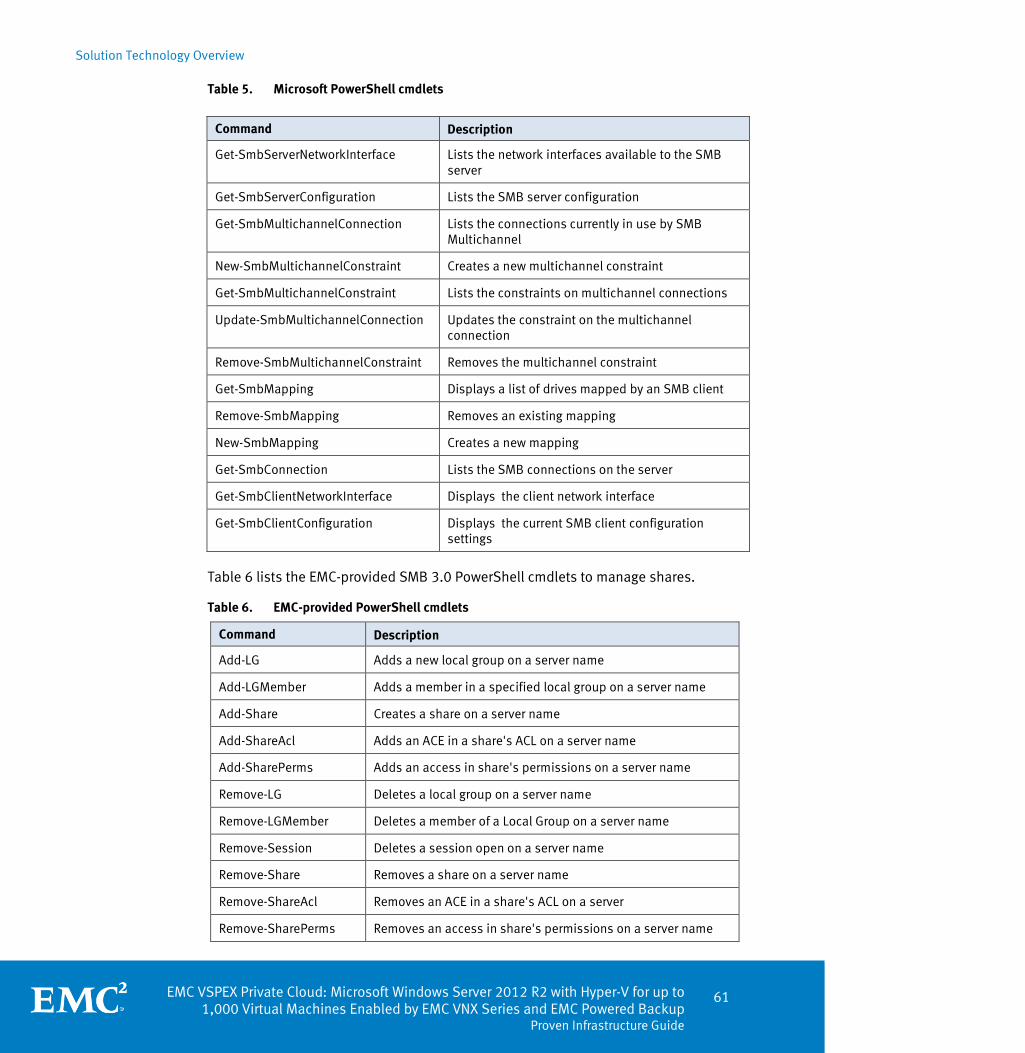
Solution Technology Overview
EMC VSPEX Private Cloud: Microsoft Windows Server 2012 R2 with Hyper-V for up to 1,000 Virtual Machines Enabled by EMC VNX Series and EMC Powered Backup
Proven Infrastructure Guide
61
Table 5. Microsoft PowerShell cmdlets
Table 6 lists the EMC-provided SMB 3.0 PowerShell cmdlets to manage shares.
Table 6. EMC-provided PowerShell cmdlets
Command Description
Add-LG Adds a new local group on a server name
Add-LGMember Adds a member in a specified local group on a server name
Add-Share Creates a share on a server name
Add-ShareAcl Adds an ACE in a share's ACL on a server name
Add-SharePerms Adds an access in share's permissions on a server name
Remove-LG Deletes a local group on a server name
Remove-LGMember Deletes a member of a Local Group on a server name
Remove-Session Deletes a session open on a server name
Remove-Share Removes a share on a server name
Remove-ShareAcl Removes an ACE in a share's ACL on a server
Remove-SharePerms Removes an access in share's permissions on a server name
Command Description
Get-SmbServerNetworkInterface Lists the network interfaces available to the SMB server
Get-SmbServerConfiguration Lists the SMB server configuration
Get-SmbMultichannelConnection Lists the connections currently in use by SMB Multichannel
New-SmbMultichannelConstraint Creates a new multichannel constraint
Get-SmbMultichannelConstraint Lists the constraints on multichannel connections
Update-SmbMultichannelConnection Updates the constraint on the multichannel connection
Remove-SmbMultichannelConstraint Removes the multichannel constraint
Get-SmbMapping Displays a list of drives mapped by an SMB client
Remove-SmbMapping Removes an existing mapping
New-SmbMapping Creates a new mapping
Get-SmbConnection Lists the SMB connections on the server
Get-SmbClientNetworkInterface Displays the client network interface
Get-SmbClientConfiguration Displays the current SMB client configuration settings

Solution Technology Overview
62 EMC VSPEX Private Cloud: Microsoft Windows Server 2012 R2 with Hyper-V for up to 1,000 Virtual Machines Enabled by EMC VNX Series and EMC Powered Backup Proven Infrastructure Guide
Command Description
Set-ShareFlags Sets share flags on a specified server name
Show-AccountSid Displays SID of a specified user
Show-ACL Displays the share's ACL on a server name
Show-LG Enumerates local group on a server name
Show-LGMembers Enumerates members of a local group on a server name
Show-RootDirMembers Lists the root directory members of a server name
Show-SecurityEventLog Displays the eventlogs of a server name
Show-Sessions Enumerates open sessions on a server name
Show-Shares Displays all shares on a server name
Show-ShareAcl Displays the share's ACL on a server name
Show-ShareFlags Displays the share's flags values on a server name
Show-SharePerms Enumerates access contained in a share's permissions on a server name
The following are some examples of the PowerShell cmdlets:
Show Shares command
Figure 28 shows a list of all the SMB 3.0 shares on the VNX from the Show Shares command.
Figure 28. PowerShell execution of Show Shares
Get-SmbServerConfiguration command
Figure 29 shows the SMB 3.0 server configuration from the Get-SMBServerConfiguration command.
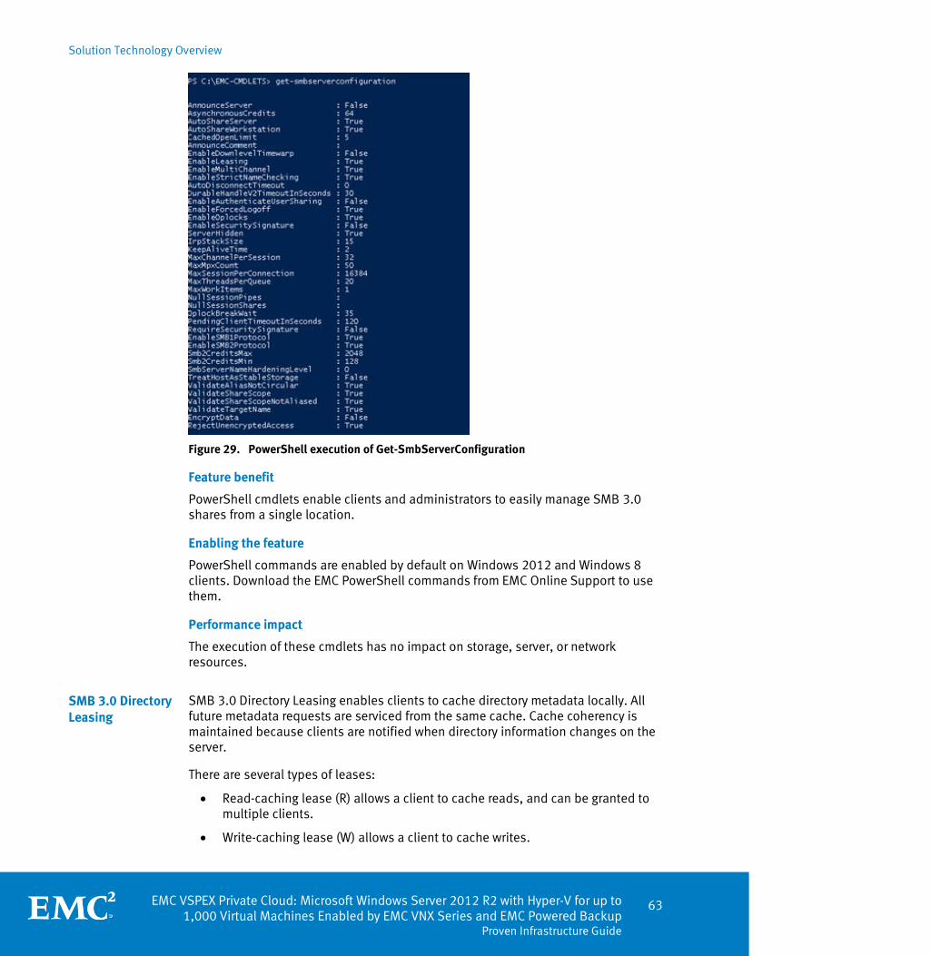
Solution Technology Overview
EMC VSPEX Private Cloud: Microsoft Windows Server 2012 R2 with Hyper-V for up to 1,000 Virtual Machines Enabled by EMC VNX Series and EMC Powered Backup
Proven Infrastructure Guide
63
Figure 29. PowerShell execution of Get-SmbServerConfiguration
Feature benefit
PowerShell cmdlets enable clients and administrators to easily manage SMB 3.0 shares from a single location.
Enabling the feature
PowerShell commands are enabled by default on Windows 2012 and Windows 8 clients. Download the EMC PowerShell commands from EMC Online Support to use them.
Performance impact
The execution of these cmdlets has no impact on storage, server, or network resources.
SMB 3.0 Directory Leasing enables clients to cache directory metadata locally. All future metadata requests are serviced from the same cache. Cache coherency is maintained because clients are notified when directory information changes on the server.
There are several types of leases:
Read-caching lease (R) allows a client to cache reads, and can be granted to multiple clients.
Write-caching lease (W) allows a client to cache writes.
SMB 3.0 Directory Leasing
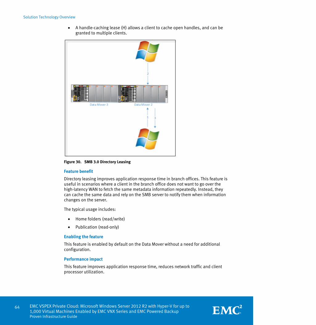
Solution Technology Overview
64 EMC VSPEX Private Cloud: Microsoft Windows Server 2012 R2 with Hyper-V for up to 1,000 Virtual Machines Enabled by EMC VNX Series and EMC Powered Backup Proven Infrastructure Guide
A handle-caching lease (H) allows a client to cache open handles, and can be granted to multiple clients.
Figure 30. SMB 3.0 Directory Leasing
Feature benefit
Directory leasing improves application response time in branch offices. This feature is useful in scenarios where a client in the branch office does not want to go over the high-latency WAN to fetch the same metadata information repeatedly. Instead, they can cache the same data and rely on the SMB server to notify them when information changes on the server.
The typical usage includes:
Home folders (read/write)
Publication (read-only)
Enabling the feature
This feature is enabled by default on the Data Mover without a need for additional configuration.
Performance impact
This feature improves application response time, reduces network traffic and client processor utilization.
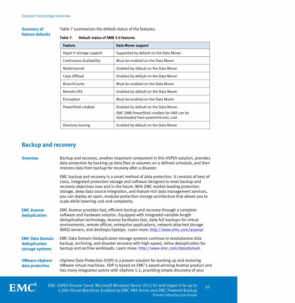
Solution Technology Overview
EMC VSPEX Private Cloud: Microsoft Windows Server 2012 R2 with Hyper-V for up to 1,000 Virtual Machines Enabled by EMC VNX Series and EMC Powered Backup
Proven Infrastructure Guide
65
Table 7 summarizes the default status of the features.
Table 7. Default status of SMB 3.0 features
Feature Data Mover support
Hyper-V storage support Supported by default on the Data Mover
Continuous Availability Must be enabled on the Data Mover
Multichannel Enabled by default on the Data Mover
Copy Offload Enabled by default on the Data Mover
BranchCache Must be enabled on the Data Mover
Remote VSS Enabled by default on the Data Mover
Encryption Must be enabled on the Data Mover
PowerShell cmdlets Enabled by default on the Data Mover.
EMC SMB PowerShell cmdlets for VNX can be downloaded from powerlink.emc.com
Directory leasing Enabled by default on the Data Mover
Backup and recovery
Backup and recovery, another important component in this VSPEX solution, provides data protection by backing up data files or volumes on a defined schedule, and then restores data from backup for recovery after a disaster.
EMC backup and recovery is a smart method of data protection. It consists of best of class, integrated protection storage and software designed to meet backup and recovery objectives now and in the future. With EMC market-leading protection storage, deep data source integration, and feature-rich data management services, you can deploy an open, modular protection storage architecture that allows you to scale while lowering cost and complexity.
EMC Avamar provides fast, efficient backup and recovery through a complete software and hardware solution. Equipped with integrated variable-length deduplication technology, Avamar facilitates fast, daily full backups for virtual environments, remote offices, enterprise applications, network-attached storage (NAS) servers, and desktops/laptops. Learn more: http://www.emc.com/avamar
EMC Data Domain Deduplication storage systems continue to revolutionize disk backup, archiving, and disaster recovery with high-speed, inline deduplication for backup and archive workloads. Learn more: http://www.emc.com/datadomain
vSphere Data Protection (VDP) is a proven solution for backing up and restoring VMware virtual machines. VDP is based on EMC’s award-winning Avamar product and has many integration points with vSphere 5.5, providing simple discovery of your
Summary of feature defaults
Overview
EMC Avamar deduplication
EMC Data Domain deduplication storage systems
VMware vSphere data protection
Solution Technology Overview
66 EMC VSPEX Private Cloud: Microsoft Windows Server 2012 R2 with Hyper-V for up to 1,000 Virtual Machines Enabled by EMC VNX Series and EMC Powered Backup Proven Infrastructure Guide
virtual machines and efficient policy creation. One of challenges that traditional systems have with virtual machines is the large amount of data that these files contain. VDP’s usage of a variable-length deduplication algorithm ensures a minimum amount of disk space is used and reduces ongoing backup storage growth. Data is deduplicated across all virtual machines associated with the VDP virtual appliance.
VDP uses vStorage APIs for Data Protection (VADP), which sends only the changed blocks of data, resulting in only a fraction of the data being sent over the network. VDP enables up to eight virtual machines to be backed up concurrently. Because VDP resides in a dedicated virtual appliance, all the backup processes are offloaded from the production virtual machines.
VDP can alleviate the burdens of restore requests from administrators by enabling end users to restore their own files using a web-based tool called vSphere Data Protection Restore Client. Users can browse their system’s backups in an easy to use interface that provides search and version control features. The users can restore individual files or directories without any intervention from IT, freeing up valuable time and resources, resulting in a better end user experience.
For backup and recovery options, refer to EMC Backup and Recovery Options for VSPEX Private Clouds Design and Implementation Guide.
Continuous availability
EMC RecoverPoint is an enterprise-scale solution that protects application data on heterogeneous SAN-attached servers and storage arrays. EMC RecoverPoint runs on a dedicated appliance (RPA) and combines industry-leading continuous data protection technology with a bandwidth-efficient, no-data-loss replication technology, allowing it to protect data locally (continuous data protection, CDP), remotely (continuous remote replication, CRR), or both (local and remote replication, CLR).
RecoverPoint CDP replicates data within the same site or to a local bunker site some distance away, and the data is transferred by FC.
RecoverPoint CRR uses either FC or an existing IP network to send the data snapshots to the remote site using techniques that preserve write-order.
In a CLR configuration, RecoverPoint replicates to both a local and a remote site simultaneously.
RecoverPoint uses lightweight splitting technology on the application server, in the fabric or in the array, to mirror application writes to the RecoverPoint cluster. RecoverPoint supports several types of write splitters:
Array-based
Intelligent fabric-based
Host-based
EMC RecoverPoint

Solution Technology Overview
EMC VSPEX Private Cloud: Microsoft Windows Server 2012 R2 with Hyper-V for up to 1,000 Virtual Machines Enabled by EMC VNX Series and EMC Powered Backup
Proven Infrastructure Guide
67
EMC VNX Replicator is a powerful, easy-to-use asynchronous replication solution. With its WAN-aware functionality, simple management interface, and advanced DR capability, it provides a complete replication solution. Replication between a primary and a secondary file system or iSCSI LUN can be on the same VNX system, or on a remote system.
EMC VNX Replicator supports application-consistent iSCSI replication. The host can initiate the replication via the VSS interface in Windows environments or Replication Manager.
For CIFS environments, the Virtual Data Mover (VDM) functionality replicates the necessary context to the remote site along with the file systems. This includes CIFS server data, audit logs, and local groups.
For asynchronous data recovery, the secondary copy can be read/write, and production can continue at the remote site. If the primary system becomes available, incremental changes at the secondary copy can be played back to the primary with the resynchronization function. This operates as described above, with a role reversal between primary and secondary.
EMC VNX Replicator
Solution Technology Overview
68 EMC VSPEX Private Cloud: Microsoft Windows Server 2012 R2 with Hyper-V for up to 1,000 Virtual Machines Enabled by EMC VNX Series and EMC Powered Backup Proven Infrastructure Guide
Other technologies
In addition to the required technical components for EMC VSPEX solutions, other items may provide additional value depending on the specific use case.
EMC XtremCache™ is a server flash caching solution that reduces latency and increases throughput to improve application performance by using intelligent caching software and PCIe flash technology.
Server-side flash caching for maximum speed
XtremCache performs the following functions to improve system performance:
Caches the most frequently referenced data on the server-based PCIe card to put the data closer to the application.
Automatically adapts to changing workloads by determining the most frequently referenced data and promoting it to the server flash card. This means that the “hottest” data (most active data) automatically resides on the PCIe card in the server for faster access.
Offloads the read traffic from the storage array, which allocates greater processing power to other applications. While one application accelerates with XtremCache, the array performance for other applications remains the same or slightly enhanced.
Write-through caching to the array for total protection
XtremCache accelerates reads and protects data by using a write-through cache to the storage to deliver persistent high-availability, integrity, and disaster recovery.
Application agnostic
XtremCache is transparent to applications; there is no need to rewrite, retest, or recertify to deploy XtremCache in the environment.
Minimum impact on system resources
Unlike other caching solutions on the market, XtremCache does not require a significant amount of memory or CPU cycles, as all flash and wear-leveling management are done on the PCIe card without using server resources. Unlike other PCIe solutions, there is no significant overhead from using XtremCache on server resources.
XtremCache creates the most efficient and intelligent I/O path from the application to the datastore, which results in an infrastructure that is dynamically optimized for performance, intelligence, and protection for both physical and virtual environments.
XtremCache active/passive clustering support
The configuration of XtremCache clustering scripts ensures that stale data is never retrieved. The scripts use cluster management events to trigger a mechanism that purges the cache. The XtremCache-enabled active/passive cluster ensures data integrity, and accelerates application performance.
EMC XtremCache

Solution Technology Overview
EMC VSPEX Private Cloud: Microsoft Windows Server 2012 R2 with Hyper-V for up to 1,000 Virtual Machines Enabled by EMC VNX Series and EMC Powered Backup
Proven Infrastructure Guide
69
XtremCache performance considerations
XtremCache performance considerations include:
On a write request, XtremCache first writes to the array, then to the cache, and then completes the application I/O.
On a read request, XtremCache satisfies the request with cached data, or, when the data is not present, retrieves the data from the array, writes it to the cache, and then returns it to the application. The trip to the array can be in the order of milliseconds; therefore, the array limits how fast the cache can work. As the number of writes increases, XtremCache performance decreases.
XtremCache is most effective for workloads with a 70 percent or greater read/write ratio, with small, random I/O (8 K is ideal). I/O greater than 128 K is not cached in XtremCache 1.5.
Note: For more information, refer to the Introduction to EMC XtremCache White Paper.


EMC VSPEX Private Cloud: Microsoft Windows Server 2012 R2 with Hyper-V for up to 1,000 Virtual Machines Enabled by EMC VNX Series and EMC Powered Backup
Proven Infrastructure Guide
71
Chapter 4 Solution Architecture Overview
This chapter presents the following topics:
Overview .................................................................................................................. 72
Solution architecture ............................................................................................... 72
Server configuration guidelines ............................................................................... 82
Network configuration guidelines ............................................................................ 87
Storage configuration guidelines ............................................................................. 90
High-availability and failover ................................................................................. 105
Validation test profile ............................................................................................ 107
Backup and recovery configuration guidelines ....................................................... 108
Sizing guidelines ................................................................................................... 108
Reference workload................................................................................................ 108
Applying the reference workload............................................................................ 109

Solution Architecture Overview
72 EMC VSPEX Private Cloud: Microsoft Windows Server 2012 R2 with Hyper-V for up to 1,000 Virtual Machines Enabled by EMC VNX Series and EMC Powered Backup Proven Infrastructure Guide
Overview
This chapter is a comprehensive guide to the major architectural aspects of this solution. Server capacity is presented in generic terms for required minimums of CPU, memory, and network resources; the customer is free to select the server and networking hardware that meet or exceed the stated minimums. The specified storage architecture, along with a system meeting the server and network requirements outlined, has been validated by EMC to provide high levels of performance while delivering a highly available architecture for your private cloud deployment.
Each VSPEX Proven Infrastructure balances the storage, network, and compute resources needed for a number of virtual machines validated by EMC. In practice, each virtual machine has its own set of requirements that rarely fit a predefined idea of a virtual machine. In any discussion about virtual infrastructures, it is important to first define a reference workload. Not all servers perform the same tasks, and it is impractical to build a reference that takes into account every possible combination of workload characteristics.
Solution architecture
The VSPEX private cloud solution for Microsoft Hyper-V with VNX validates at four different points of scale: one configuration with up to 200 virtual machines , one configuration with up to 300 virtual machines, one configuration with up to 600 virtual machines, and one configuration with up to 1,000 virtual machines. The defined configurations form the basis of creating a custom solution.
Note: VSPEX uses the concept of a reference workload to describe and define a virtual machine. Therefore, one physical or virtual server in an existing environment may not be equal to one virtual machine in a VSPEX solution. Evaluate your workload in terms of the reference to arrive at an appropriate point of scale. This document describes the process in Applying the reference workload.
Overview
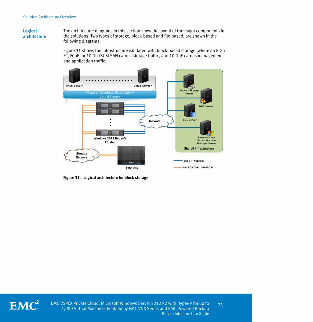
Solution Architecture Overview
EMC VSPEX Private Cloud: Microsoft Windows Server 2012 R2 with Hyper-V for up to 1,000 Virtual Machines Enabled by EMC VNX Series and EMC Powered Backup
Proven Infrastructure Guide
73
The architecture diagrams in this section show the layout of the major components in the solutions. Two types of storage, block-based and file-based, are shown in the following diagrams.
Figure 31 shows the infrastructure validated with block-based storage, where an 8 Gb FC, FCoE, or 10 Gb-iSCSI SAN carries storage traffic, and 10 GbE carries management and application traffic.
Figure 31. Logical architecture for block storage
Logical architecture

Solution Architecture Overview
74 EMC VSPEX Private Cloud: Microsoft Windows Server 2012 R2 with Hyper-V for up to 1,000 Virtual Machines Enabled by EMC VNX Series and EMC Powered Backup Proven Infrastructure Guide
Figure 32 shows the infrastructure validated with file-based storage, where 10 GbE carries storage traffic and all other traffic.
Figure 32. Logical architecture for file storage
The architectures include the following key components:
Microsoft Hyper-V—Provides a common virtualization layer to host a server environment. The specifics of the validated environment are listed in Table 8. Hyper-V provides highly available infrastructure through features such as:
Live Migration — Provides live migration of virtual machines within a virtual infrastructure cluster, with no virtual machine downtime or service disruption.
Live Storage Migration — Provides live migration of virtual machine disk files within and across storage arrays with no virtual machine downtime or service disruption.
Failover Clustering High Availability (HA) – Detects and provides rapid recovery for a failed virtual machine in a cluster.
Dynamic Optimization (DO) – Provides load balancing of computing capacity in a cluster with support of SCVMM.
Microsoft System Center Virtual Machine Manager (SCVMM)—SCVMM is not required for this solution. However, if deployed, it (or its corresponding functionality in Microsoft System Center Essentials) simplifies provisioning, management, and monitoring of the Hyper-V environment.
Microsoft SQL Server 2012—SCVMM, if used, requires a SQL Server database instance to store configuration and monitoring details.
Key components

Solution Architecture Overview
EMC VSPEX Private Cloud: Microsoft Windows Server 2012 R2 with Hyper-V for up to 1,000 Virtual Machines Enabled by EMC VNX Series and EMC Powered Backup
Proven Infrastructure Guide
75
DNS Server —Use DNS services for the various solution components to perform name resolution. This solution uses Microsoft DNS service running on Windows Server 2012 R2 .
Active Directory Server — Various solution components require Active Directory services to function properly. The Microsoft AD Service runs on a Windows Server 2012 R2 .
IP network—A standard Ethernet network carries all network traffic with redundant cabling and switching. A shared IP network carries user and management traffic.
Storage network
The storage network is an isolated network that provides hosts with access to the storage arrays. VSPEX offers different options for block-based and file-based storage.
Storage network for block This solution provides three options for block-based storage networks.
Fibre Channel (FC)—A set of standards that define protocols for performing high speed serial data transfer. FC provides a standard data transport frame among servers and shared storage devices.
Fibre Channel over Ethernet (FCoE)—A newer storage networking protocol that supports FC natively over Ethernet, by encapsulating FC frames into Ethernet frames. This allows the encapsulated FC frames to run alongside traditional Internet Protocol (IP) traffic.
10 Gb Ethernet (iSCSI)—Enables the transport of SCSI blocks over a TCP/IP network. iSCSI works by encapsulating SCSI commands into TCP packets and sending the packets over the IP network.
Storage network for file With file-based storage, a private, non-routable 10 GbE subnet carries the storage traffic.
VNX storage array
The VSPEX private cloud configuration begins with the VNX family storage arrays, including:
EMC VNX5200 array — Provides storage by presenting either Cluster Shared Volumes (for block) or CIFS (SMB 3.0) shares (for file) to Hyper-V hosts for up to 200 virtual machines.
EMC VNX5400 array — Provides storage by presenting either Cluster Shared Volumes (for block) or CIFS (SMB 3.0) shares (for file) to Hyper-V hosts for up to 300 virtual machines.
EMC VNX5600 array — Provides storage by presenting either Cluster Shared Volumes (for block) or CIFS (SM B3.0) shares (for file) to Hyper-V hosts for up to 600 virtual machines.
EMC VNX5800 array — Provides storage by presenting either Cluster Shared Volumes (for block) or CIFS (SMB 3.0) shares (for file) to Hyper-V hosts for up to 1,000 virtual machines.
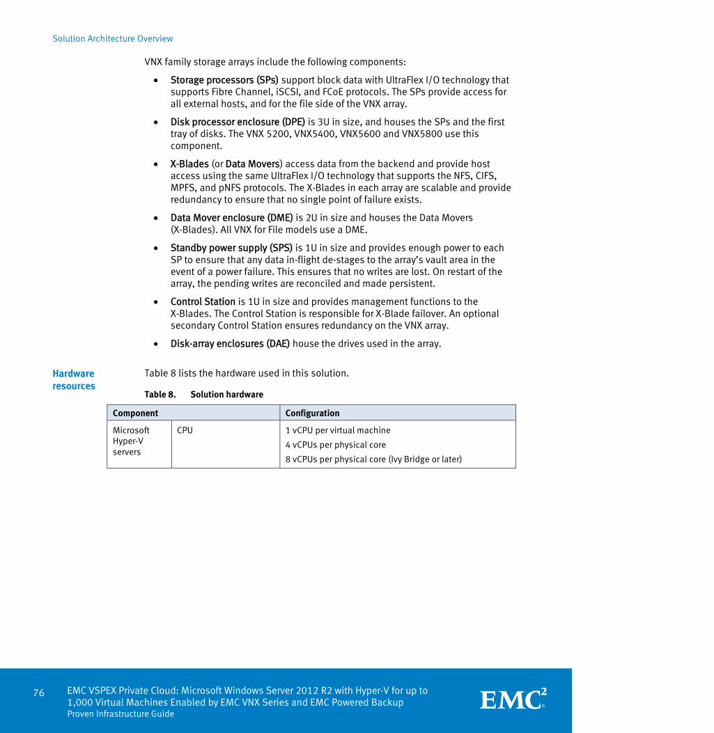
Solution Architecture Overview
76 EMC VSPEX Private Cloud: Microsoft Windows Server 2012 R2 with Hyper-V for up to 1,000 Virtual Machines Enabled by EMC VNX Series and EMC Powered Backup Proven Infrastructure Guide
VNX family storage arrays include the following components:
Storage processors (SPs) support block data with UltraFlex I/O technology that supports Fibre Channel, iSCSI, and FCoE protocols. The SPs provide access for all external hosts, and for the file side of the VNX array.
Disk processor enclosure (DPE) is 3U in size, and houses the SPs and the first tray of disks. The VNX 5200, VNX5400, VNX5600 and VNX5800 use this component.
X-Blades (or Data Movers) access data from the backend and provide host access using the same UltraFlex I/O technology that supports the NFS, CIFS, MPFS, and pNFS protocols. The X-Blades in each array are scalable and provide redundancy to ensure that no single point of failure exists.
Data Mover enclosure (DME) is 2U in size and houses the Data Movers (X-Blades). All VNX for File models use a DME.
Standby power supply (SPS) is 1U in size and provides enough power to each SP to ensure that any data in-flight de-stages to the array’s vault area in the event of a power failure. This ensures that no writes are lost. On restart of the array, the pending writes are reconciled and made persistent.
Control Station is 1U in size and provides management functions to the X-Blades. The Control Station is responsible for X-Blade failover. An optional secondary Control Station ensures redundancy on the VNX array.
Disk-array enclosures (DAE) house the drives used in the array.
Table 8 lists the hardware used in this solution.
Table 8. Solution hardware
Component Configuration
Microsoft Hyper-V servers
CPU 1 vCPU per virtual machine
4 vCPUs per physical core
8 vCPUs per physical core (Ivy Bridge or later)
Hardware resources

Solution Architecture Overview
EMC VSPEX Private Cloud: Microsoft Windows Server 2012 R2 with Hyper-V for up to 1,000 Virtual Machines Enabled by EMC VNX Series and EMC Powered Backup
Proven Infrastructure Guide
77
Component Configuration
For 200 virtual machines:
200 vCPUs
Minimum of 50 physical CPUs
Minimum of 25 physical CPUs (Ivy Bridge or later)
For 300 virtual machines:
300 vCPUs
Minimum of 75 physical CPUs
Minimum of 38 physical CPUs (Ivy Bridge or later)
For 600 virtual machines:
600 vCPUs
Minimum of 150 physical CPUs
Minimum of 75 physical CPUs (Ivy Bridge or later)
For 1,000 virtual machines:
1,000 vCPUs
Minimum of 250 physical CPUs
Minimum of 125 physical CPUs (Ivy Bridge or later)
Memory 2 GB RAM per virtual machine
2 GB RAM reservation per Hyper-V host
For 200 virtual machines:
Minimum of 400 GB RAM
Add 2GB for each physical server
For 300 virtual machines:
Minimum of 600 GB RAM
Add 2GB for each physical server
For 600 virtual machines:
Minimum of 1200 GB RAM
Add 2GB for each physical server
For 1,000 virtual machines:
Minimum of 2000 GB RAM
Add 2GB for each physical server
Network
Block 2 x 10 GbE NICs per server
2 HBAs per server
File 4 x 10 GbE NICs per server
Note: Add at least one additional server to the infrastructure beyond the minimum requirements to implement Microsoft Hyper-V High-Availability (HA) and meet the listed minimums.

Solution Architecture Overview
78 EMC VSPEX Private Cloud: Microsoft Windows Server 2012 R2 with Hyper-V for up to 1,000 Virtual Machines Enabled by EMC VNX Series and EMC Powered Backup Proven Infrastructure Guide
Component Configuration
Network infrastructure
Minimum switching capacity
Block 2 physical switches
2 x 10 GbE ports per Hyper-V server
1 x 1 GbE port per Control Station for management
2 ports per Hyper-V server, for storage network
2 ports per SP, for storage data
File 2 physical switches
4 x 10 GbE ports per Hyper-V server
1 x 1 GbE port per Control Station for management
2 x 10 GbE ports per Data Mover for data
EMC Backup Avamar Refer to EMC Backup and Recovery Options for VSPEX Private Clouds White Paper.
Data Domain Refer to EMC Backup and Recovery Options for VSPEX Private Clouds White Paper.
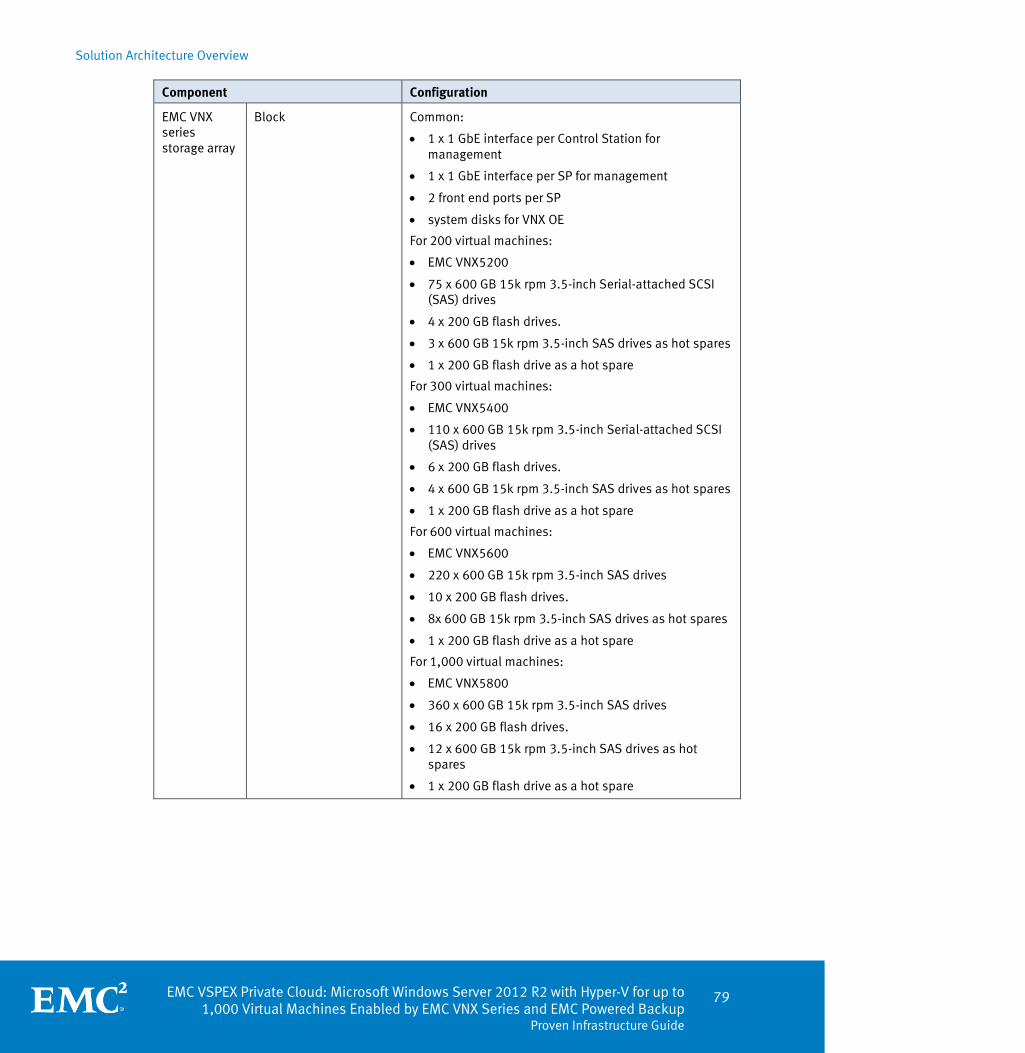
Solution Architecture Overview
EMC VSPEX Private Cloud: Microsoft Windows Server 2012 R2 with Hyper-V for up to 1,000 Virtual Machines Enabled by EMC VNX Series and EMC Powered Backup
Proven Infrastructure Guide
79
Component Configuration
EMC VNX series storage array
Block Common:
1 x 1 GbE interface per Control Station for management
1 x 1 GbE interface per SP for management
2 front end ports per SP
system disks for VNX OE
For 200 virtual machines:
EMC VNX5200
75 x 600 GB 15k rpm 3.5-inch Serial-attached SCSI (SAS) drives
4 x 200 GB flash drives.
3 x 600 GB 15k rpm 3.5-inch SAS drives as hot spares
1 x 200 GB flash drive as a hot spare
For 300 virtual machines:
EMC VNX5400
110 x 600 GB 15k rpm 3.5-inch Serial-attached SCSI (SAS) drives
6 x 200 GB flash drives.
4 x 600 GB 15k rpm 3.5-inch SAS drives as hot spares
1 x 200 GB flash drive as a hot spare
For 600 virtual machines:
EMC VNX5600
220 x 600 GB 15k rpm 3.5-inch SAS drives
10 x 200 GB flash drives.
8x 600 GB 15k rpm 3.5-inch SAS drives as hot spares
1 x 200 GB flash drive as a hot spare
For 1,000 virtual machines:
EMC VNX5800
360 x 600 GB 15k rpm 3.5-inch SAS drives
16 x 200 GB flash drives.
12 x 600 GB 15k rpm 3.5-inch SAS drives as hot spares
1 x 200 GB flash drive as a hot spare

Solution Architecture Overview
80 EMC VSPEX Private Cloud: Microsoft Windows Server 2012 R2 with Hyper-V for up to 1,000 Virtual Machines Enabled by EMC VNX Series and EMC Powered Backup Proven Infrastructure Guide
Component Configuration
File Common:
2 x 10 GbE interfaces per Data Mover
1 x 1 GbE interface per Control Station for management
1 x 1 GbE interface per SP for management
System disks for VNX OE
For 200 virtual machines
EMC VNX5200
2 Data Movers (active/standby)
75 x 600 GB 15k rpm 3.5-inch SAS drives
4 x 200 GB flash drives.
3 x 600 GB 15k rpm 3.5-inch SAS drives as hot spares
1 x 200 GB flash drive as a hot spare
For 300 virtual machines
EMC VNX5400
2 Data Movers (active/standby)
110 x 600 GB 15k rpm 3.5-inch SAS drives
6 x 200 GB flash drives.
5 x 600 GB 15k rpm 3.5-inch SAS drives as hot spares
1 x 200 GB flash drive as a hot spare
For 600 virtual machines
EMC VNX5600
2 Data Movers (active/standby)
220 x 600 GB 15k rpm 3.5-inch SAS drives
10 x 200 GB flash drives.
8 x 600 GB 15k rpm 3.5-inch SAS drives as hot spares
1 x 200 GB flash drive as a hot spare
For 1,000 virtual machines
EMC VNX5800
3 Data Movers (2 active/1 standby)
360 x 600 GB 15k rpm 3.5-inch SAS drives
16 x 200 GB flash drives.
12 x 600 GB 15k rpm 3.5-inch SAS drives as hot spares
1 x 200 GB flash drive as a hot spare
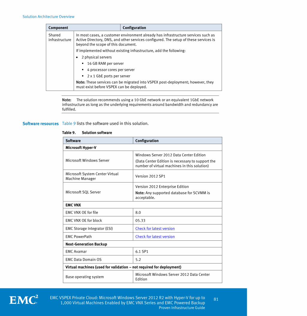
Solution Architecture Overview
EMC VSPEX Private Cloud: Microsoft Windows Server 2012 R2 with Hyper-V for up to 1,000 Virtual Machines Enabled by EMC VNX Series and EMC Powered Backup
Proven Infrastructure Guide
81
Component Configuration
Shared infrastructure
In most cases, a customer environment already has infrastructure services such as Active Directory, DNS, and other services configured. The setup of these services is beyond the scope of this document.
If implemented without existing infrastructure, add the following:
2 physical servers
16 GB RAM per server
4 processor cores per server
2 x 1 GbE ports per server
Note: These services can be migrated into VSPEX post-deployment; however, they must exist before VSPEX can be deployed.
Note: The solution recommends using a 10 GbE network or an equivalent 1GbE network infrastructure as long as the underlying requirements around bandwidth and redundancy are fulfilled.
Table 9 lists the software used in this solution.
Table 9. Solution software
Software Configuration
Microsoft Hyper-V
Microsoft Windows Server Windows Server 2012 Data Center Edition
(Data Center Edition is necessary to support the number of virtual machines in this solution)
Microsoft System Center Virtual Machine Manager
Version 2012 SP1
Microsoft SQL Server Version 2012 Enterprise Edition
Note: Any supported database for SCVMM is acceptable.
EMC VNX
EMC VNX OE for file 8.0
EMC VNX OE for block 05.33
EMC Storage Integrator (ESI) Check for latest version
EMC PowerPath Check for latest version
Next-Generation Backup
EMC Avamar 6.1 SP1
EMC Data Domain OS 5.2
Virtual machines (used for validation – not required for deployment)
Base operating system Microsoft Windows Server 2012 Data Center Edition
Software resources
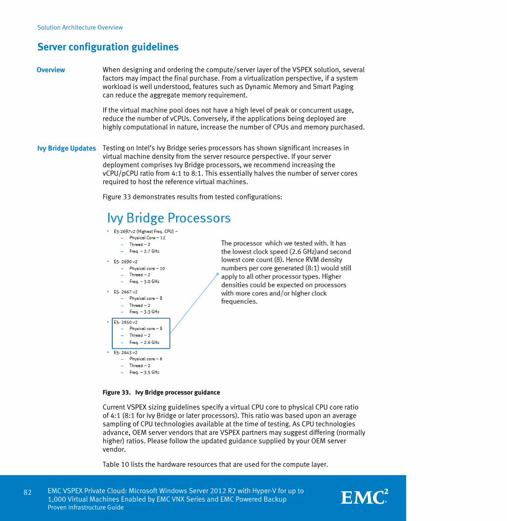
Solution Architecture Overview
82 EMC VSPEX Private Cloud: Microsoft Windows Server 2012 R2 with Hyper-V for up to 1,000 Virtual Machines Enabled by EMC VNX Series and EMC Powered Backup Proven Infrastructure Guide
Server configuration guidelines
When designing and ordering the compute/server layer of the VSPEX solution, several factors may impact the final purchase. From a virtualization perspective, if a system workload is well understood, features such as Dynamic Memory and Smart Paging can reduce the aggregate memory requirement.
If the virtual machine pool does not have a high level of peak or concurrent usage, reduce the number of vCPUs. Conversely, if the applications being deployed are highly computational in nature, increase the number of CPUs and memory purchased.
Testing on Intel’s Ivy Bridge series processors has shown significant increases in virtual machine density from the server resource perspective. If your server deployment comprises Ivy Bridge processors, we recommend increasing the vCPU/pCPU ratio from 4:1 to 8:1. This essentially halves the number of server cores required to host the reference virtual machines.
Figure 33 demonstrates results from tested configurations:
Figure 33. Ivy Bridge processor guidance
Current VSPEX sizing guidelines specify a virtual CPU core to physical CPU core ratio of 4:1 (8:1 for Ivy Bridge or later processors). This ratio was based upon an average sampling of CPU technologies available at the time of testing. As CPU technologies advance, OEM server vendors that are VSPEX partners may suggest differing (normally higher) ratios. Please follow the updated guidance supplied by your OEM server vendor.
Table 10 lists the hardware resources that are used for the compute layer.
Overview
Ivy Bridge Updates
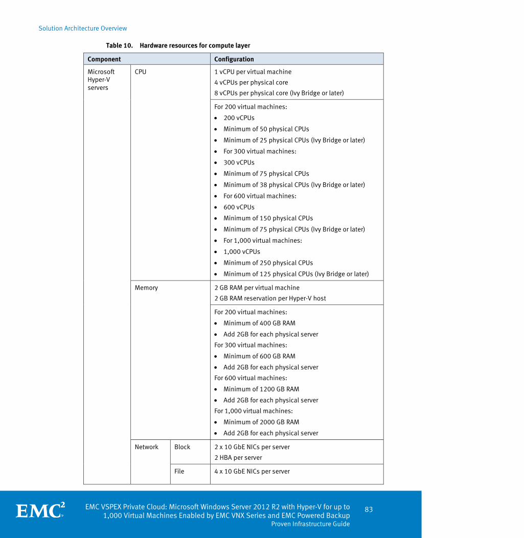
Solution Architecture Overview
EMC VSPEX Private Cloud: Microsoft Windows Server 2012 R2 with Hyper-V for up to 1,000 Virtual Machines Enabled by EMC VNX Series and EMC Powered Backup
Proven Infrastructure Guide
83
Table 10. Hardware resources for compute layer
Component Configuration
Microsoft Hyper-V servers
CPU 1 vCPU per virtual machine
4 vCPUs per physical core
8 vCPUs per physical core (Ivy Bridge or later)
For 200 virtual machines:
200 vCPUs
Minimum of 50 physical CPUs
Minimum of 25 physical CPUs (Ivy Bridge or later)
For 300 virtual machines:
300 vCPUs
Minimum of 75 physical CPUs
Minimum of 38 physical CPUs (Ivy Bridge or later)
For 600 virtual machines:
600 vCPUs
Minimum of 150 physical CPUs
Minimum of 75 physical CPUs (Ivy Bridge or later)
For 1,000 virtual machines:
1,000 vCPUs
Minimum of 250 physical CPUs
Minimum of 125 physical CPUs (Ivy Bridge or later)
Memory 2 GB RAM per virtual machine
2 GB RAM reservation per Hyper-V host
For 200 virtual machines:
Minimum of 400 GB RAM
Add 2GB for each physical server
For 300 virtual machines:
Minimum of 600 GB RAM
Add 2GB for each physical server
For 600 virtual machines:
Minimum of 1200 GB RAM
Add 2GB for each physical server
For 1,000 virtual machines:
Minimum of 2000 GB RAM
Add 2GB for each physical server
Network Block 2 x 10 GbE NICs per server
2 HBA per server
File 4 x 10 GbE NICs per server

Solution Architecture Overview
84 EMC VSPEX Private Cloud: Microsoft Windows Server 2012 R2 with Hyper-V for up to 1,000 Virtual Machines Enabled by EMC VNX Series and EMC Powered Backup Proven Infrastructure Guide
Component Configuration
Note: Add at least one additional server to the infrastructure beyond the minimum requirements to implement Hyper-V HA and meet the listed minimums.
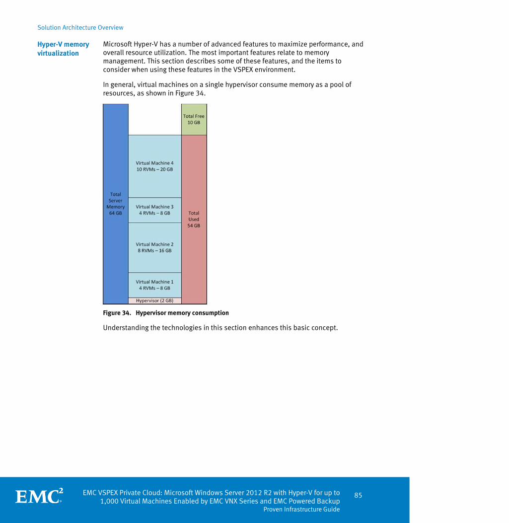
Solution Architecture Overview
EMC VSPEX Private Cloud: Microsoft Windows Server 2012 R2 with Hyper-V for up to 1,000 Virtual Machines Enabled by EMC VNX Series and EMC Powered Backup
Proven Infrastructure Guide
85
Microsoft Hyper-V has a number of advanced features to maximize performance, and overall resource utilization. The most important features relate to memory management. This section describes some of these features, and the items to consider when using these features in the VSPEX environment.
In general, virtual machines on a single hypervisor consume memory as a pool of resources, as shown in Figure 34.
Figure 34. Hypervisor memory consumption
Understanding the technologies in this section enhances this basic concept.
Hyper-V memory virtualization
Solution Architecture Overview
86 EMC VSPEX Private Cloud: Microsoft Windows Server 2012 R2 with Hyper-V for up to 1,000 Virtual Machines Enabled by EMC VNX Series and EMC Powered Backup Proven Infrastructure Guide
Dynamic Memory
Dynamic Memory was introduced in Windows Server 2008 R2 SP1 to increase physical memory efficiency by treating memory as a shared resource, and dynamically allocating it to virtual machines. The amount of memory used by each virtual machine is adjustable at any time. Dynamic Memory reclaims unused memory from idle virtual machines, which allows more virtual machines to run at any given time. In Windows Server 2012, Dynamic Memory enables administrators to dynamically increase the maximum memory available to virtual machines.
Smart Paging
Even with Dynamic Memory, Hyper-V allows more virtual machines than the available physical memory can support. In most cases, there is a memory gap between minimum memory and startup memory. Smart Paging is a memory management technique that uses disk resources as temporary memory replacement. It swaps out less-used memory to disk storage, and swaps in when needed. Performance degradation is a potential drawback of Smart Paging. Hyper-V continues to use the guest paging when the host memory is oversubscribed because it is more efficient than Smart Paging.
Non-Uniform Memory Access
Non-Uniform Memory Access (NUMA) is a multi-node computer technology that enables a CPU to access remote-node memory. This type of memory access degrades performance, so Windows Server 2012 employs a process known as processor affinity, which pins threads to a single CPU to avoid remote-node memory access. In previous versions of Windows, this feature is only available to the host. Windows Server 2012 extends this functionality to the virtual machines, which provides improved performance in symmetrical multiprocessor (SMP) environments.
The memory configuration guidelines take into account Hyper-V memory overhead, and the virtual machine memory settings.
Hyper-V memory overhead
Virtualized memory has some associated overhead, which includes the memory consumed by Hyper-V, the parent partition, and additional overhead for each virtual machine. Leave at least 2 GB memory for the Hyper-V parent partition in this solution.
Virtual machine memory
In this solution, each virtual machine gets 2 GB memory in fixed mode.
Memory configuration guidelines
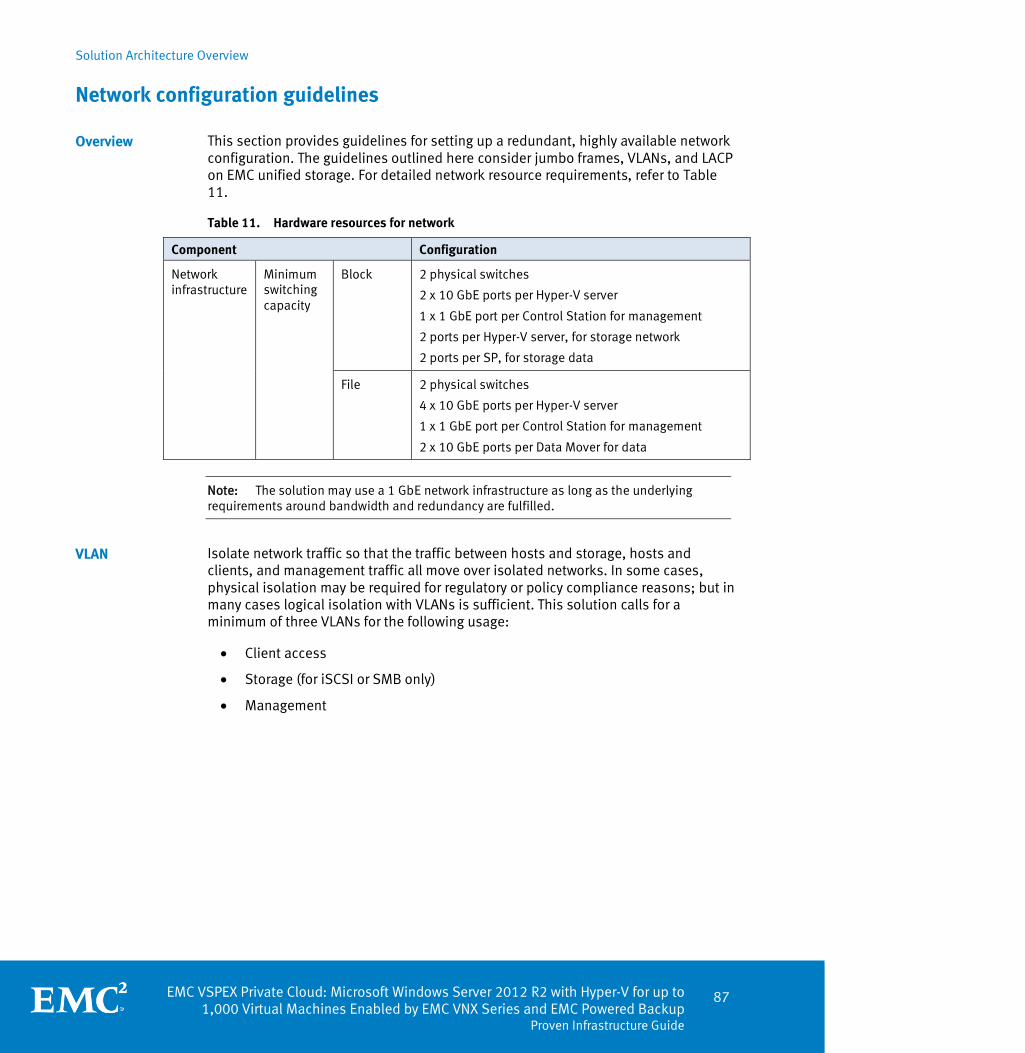
Solution Architecture Overview
EMC VSPEX Private Cloud: Microsoft Windows Server 2012 R2 with Hyper-V for up to 1,000 Virtual Machines Enabled by EMC VNX Series and EMC Powered Backup
Proven Infrastructure Guide
87
Network configuration guidelines
This section provides guidelines for setting up a redundant, highly available network configuration. The guidelines outlined here consider jumbo frames, VLANs, and LACP on EMC unified storage. For detailed network resource requirements, refer to Table 11.
Table 11. Hardware resources for network
Component Configuration
Network infrastructure
Minimum switching capacity
Block 2 physical switches
2 x 10 GbE ports per Hyper-V server
1 x 1 GbE port per Control Station for management
2 ports per Hyper-V server, for storage network
2 ports per SP, for storage data
File 2 physical switches
4 x 10 GbE ports per Hyper-V server
1 x 1 GbE port per Control Station for management
2 x 10 GbE ports per Data Mover for data
Note: The solution may use a 1 GbE network infrastructure as long as the underlying requirements around bandwidth and redundancy are fulfilled.
Isolate network traffic so that the traffic between hosts and storage, hosts and clients, and management traffic all move over isolated networks. In some cases, physical isolation may be required for regulatory or policy compliance reasons; but in many cases logical isolation with VLANs is sufficient. This solution calls for a minimum of three VLANs for the following usage:
Client access
Storage (for iSCSI or SMB only)
Management
Overview
VLAN

Solution Architecture Overview
88 EMC VSPEX Private Cloud: Microsoft Windows Server 2012 R2 with Hyper-V for up to 1,000 Virtual Machines Enabled by EMC VNX Series and EMC Powered Backup Proven Infrastructure Guide
Figure 35 depicts the VLANs and the network connectivity requirements for a block-based VNX array.
Figure 35. Required networks for block storage

Solution Architecture Overview
EMC VSPEX Private Cloud: Microsoft Windows Server 2012 R2 with Hyper-V for up to 1,000 Virtual Machines Enabled by EMC VNX Series and EMC Powered Backup
Proven Infrastructure Guide
89
Figure 36 depicts the VLANs and the network connectivity requirements for a file-based VNX array.
Figure 36. Required networks for file storage
The client access network is for users of the system, or clients, to communicate with the infrastructure. The storage network provides communication between the compute layer and the storage layer. Administrators use the management network as a dedicated way to access the management connections on the storage array, network switches, and hosts.
Note: Some best practices call for additional network isolation for cluster traffic, virtualization layer communication, and other features. Implement these additional networks if necessary.
This solution recommends setting the MTU to 9,000 (jumbo frames) for efficient storage and virtual machine migration traffic. Most switch vendors also suggest enabling baby jumbo frames (setting MTU at 2158) to prevent frame fragmentation.
Enable jumbo frames (iSCSI, FCoE, or SMB only)

Solution Architecture Overview
90 EMC VSPEX Private Cloud: Microsoft Windows Server 2012 R2 with Hyper-V for up to 1,000 Virtual Machines Enabled by EMC VNX Series and EMC Powered Backup Proven Infrastructure Guide
Refer to the switch vendor guidelines to enable jumbo frames for storage and host ports on the switches.
Link aggregation resembles an Ethernet channel, but uses the LACP IEEE 802.3ad standard. The IEEE 802.3ad standard supports link aggregations with two or more ports. All ports in the aggregation must have the same speed and be full duplex. In this solution, LACP is configured on VNX, combining multiple Ethernet ports into a single virtual device. If a link is lost in the Ethernet port, the link fails over to another port. All network traffic is distributed across the active links.
Storage configuration guidelines
This section provides guidelines for setting up the storage layer of the solution to provide high-availability and the expected level of performance.
Hyper-V allows more than one method of using storage when hosting virtual machines. The tested solutions described below use different block protocols (FC/FCoE/iSCSI) and CIFS (for file), and the storage layout described adheres to all current best practices. A customer or architect with the necessary training and background can make modifications based upon their understanding of the system usage and load if required. However, the building blocks described in this guide ensure acceptable performance. The VSPEX storage building blocks section provides specific recommendations for customization.
Table 12 lists hardware resources for storage.
Link aggregation (SMB only)
Overview
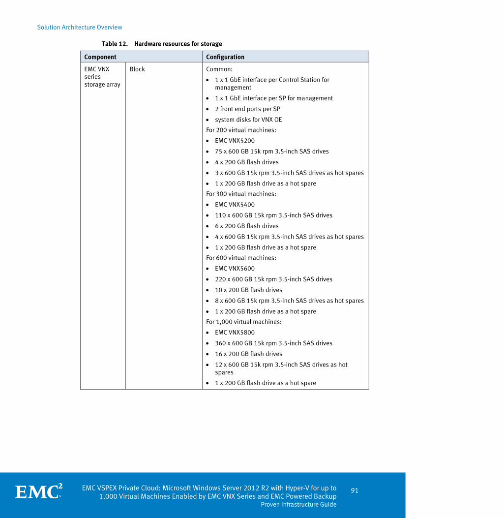
Solution Architecture Overview
EMC VSPEX Private Cloud: Microsoft Windows Server 2012 R2 with Hyper-V for up to 1,000 Virtual Machines Enabled by EMC VNX Series and EMC Powered Backup
Proven Infrastructure Guide
91
Table 12. Hardware resources for storage
Component Configuration
EMC VNX series storage array
Block Common:
1 x 1 GbE interface per Control Station for management
1 x 1 GbE interface per SP for management
2 front end ports per SP
system disks for VNX OE
For 200 virtual machines:
EMC VNX5200
75 x 600 GB 15k rpm 3.5-inch SAS drives
4 x 200 GB flash drives
3 x 600 GB 15k rpm 3.5-inch SAS drives as hot spares
1 x 200 GB flash drive as a hot spare
For 300 virtual machines:
EMC VNX5400
110 x 600 GB 15k rpm 3.5-inch SAS drives
6 x 200 GB flash drives
4 x 600 GB 15k rpm 3.5-inch SAS drives as hot spares
1 x 200 GB flash drive as a hot spare
For 600 virtual machines:
EMC VNX5600
220 x 600 GB 15k rpm 3.5-inch SAS drives
10 x 200 GB flash drives
8 x 600 GB 15k rpm 3.5-inch SAS drives as hot spares
1 x 200 GB flash drive as a hot spare
For 1,000 virtual machines:
EMC VNX5800
360 x 600 GB 15k rpm 3.5-inch SAS drives
16 x 200 GB flash drives
12 x 600 GB 15k rpm 3.5-inch SAS drives as hot spares
1 x 200 GB flash drive as a hot spare

Solution Architecture Overview
92 EMC VSPEX Private Cloud: Microsoft Windows Server 2012 R2 with Hyper-V for up to 1,000 Virtual Machines Enabled by EMC VNX Series and EMC Powered Backup Proven Infrastructure Guide
Component Configuration
File Common:
2 x 10 GbE interfaces per Data Mover
1 x 1 GbE interface per Control Station for management
1 x 1 GbE interface per SP for management
System disks for VNX OE
For 200 virtual machines:
EMC VNX5200
75 x 600 GB 15k rpm 3.5-inch SAS drives
4 x 200 GB flash drives
3 x 600 GB 15k rpm 3.5-inch SAS drives as hot spares
1 x 200 GB flash drive as a hot spare
For 300 virtual machines:
EMC VNX5400
2 Data Movers (active / standby)
110 x 600 GB 15k rpm 3.5-inch SAS drives
6 x 200 GB flash drives
4 x 600 GB 15k rpm 3.5-inch SAS drives as hot spares
1 x 200 GB flash drive as a hot spare
For 600 virtual machines:
EMC VNX5600
2 Data Movers (active / standby)
220 x 600 GB 15k rpm 3.5-inch SAS drives
10 x 200 GB flash drives
8 x 600 GB 15k rpm 3.5-inch SAS drives as hot spares
1 x 200 GB flash drive as a hot spare
For 1,000 virtual machines:
EMC VNX5800
3 Data Movers (2 x active /1 x standby)
360 x 600 GB 15k rpm 3.5-inch SAS drives
16 x 200 GB flash drives
12 x 600 GB 15k rpm 3.5-inch SAS drives as hot spares
1 x 200 GB flash drive as a hot spare
Note: For the VNX5800, EMC recommends that you run no more than 600 virtual machines on a single active Data Mover. Configure two active Data Movers (2 x active/1 x standby) when scaling to 600 or larger in that case.

Solution Architecture Overview
EMC VSPEX Private Cloud: Microsoft Windows Server 2012 R2 with Hyper-V for up to 1,000 Virtual Machines Enabled by EMC VNX Series and EMC Powered Backup
Proven Infrastructure Guide
93
This section provides guidelines to set up the storage layer of the solution to provide high-availability and the expected level of performance.
Windows Server 2012 Hyper-V and Failover Clustering use Cluster Shared Volumes v2 and VHDX features to virtualize storage presented from external shared storage system to host virtual machines. In Figure 37, the storage array presents either block-based LUNs (as CSV), or file-based CIFS share (as SMB shares) to the Windows hosts to host virtual machines.
Figure 37. Hyper-V virtual disk types
CIFS
Windows Server 2012 supports using CIFS (SMB 3.0) file shares as shared storage for a Hyper-V virtual machine.
CSV
A Cluster Shared Volume (CSV) is a shared disk containing a New Technology File System (NTFS) volume that is made accessible by all nodes of a Windows Failover Cluster. It can be deployed over any SCSI-based local or network storage.
Pass Through
Windows 2012 also supports Pass Through, which allows a virtual machine to access a physical disk mapped to the host that does not have a volume configured on it.
SMB 3.0 (file-based storage only)
The SMB protocol is the file sharing protocol that is used by default in Windows. With the introduction of Windows Server 2012, it provides a vast set of new SMB features with an updated (SMB 3.0) protocol. Some of the key features available with Windows Server 2012 SMB 3.0 are:
SMB Transparent Failover
SMB Scale Out
SMB Multichannel
Hyper-V storage virtualization for VSPEX

Solution Architecture Overview
94 EMC VSPEX Private Cloud: Microsoft Windows Server 2012 R2 with Hyper-V for up to 1,000 Virtual Machines Enabled by EMC VNX Series and EMC Powered Backup Proven Infrastructure Guide
SMB Direct
SMB Encryption
VSS for SMB file shares
SMB Directory Leasing
SMB PowerShell
With these new features, SMB 3.0 offers richer capabilities that, when combined, provide organizations with a high performance storage alternative to traditional Fibre Channel storage solutions at a lower cost.
Note: For more details about SMB 3.0, refer to Chapter 3.
ODX
Offloaded Data Transfer (ODX) is a feature of the storage stack in Microsoft Windows Server 2012 that gives users the ability to use the investment in external storage arrays to offload data transfers from the server to the storage arrays. When used with storage hardware that supports the ODX feature, file copy operations are initiated by the host, but performed by the storage device. ODX eliminates the data transfer between the storage and the Hyper-V hosts by using a token-based mechanism for reading and writing data within storage arrays and reduces the load on your network and hosts.
Using ODX helps to enable rapid cloning and migration of virtual machines. Because the file transfer is offloading to the storage array when using ODX, the host resource usage, such as CPU and network, is significantly reduced. By maximizing the use of storage array, ODX minimizes latencies and improve the transfer speed of large files, such as database or video files.
When performing file operations that are supported by ODX, data transfers are automatically offloaded to the storage array and are transparent to users. ODX is enabled by default in Windows Server 2012.
VHDX
Hyper-V in Windows Server 2012 contains an update to the VHD format called VHDX, which has much larger capacity and built-in resiliency. The main features of the VHDX format are:
Support for virtual hard disk storage with the capacity of up to 64 TB.
Additional protection against data corruption during power failures by logging updates to the VHDX metadata structures.
Optimal structure alignment of the virtual hard disk format to suit large sector disks.
The VHDX format also has the following features:
Larger block size for dynamic and differential disks, which enables the disks to better meet the needs of the workload.

Solution Architecture Overview
EMC VSPEX Private Cloud: Microsoft Windows Server 2012 R2 with Hyper-V for up to 1,000 Virtual Machines Enabled by EMC VNX Series and EMC Powered Backup
Proven Infrastructure Guide
95
The 4 KB logical sector virtual disk that enables increased performance when used by applications and workloads that are designed for 4 KB sectors.
The ability to store custom metadata about the files that the user might want to record, such as the operating system version or applied updates.
Space reclamation features that can result in smaller file size and enable the underlying physical storage device to reclaim unused space (for example, TRIM requires direct-attached storage or SCSI disks and TRIM-compatible hardware).
Sizing the storage system to meet virtual server IOPS is a complicated process. When I/O reaches the storage array, several components such as the Data Mover (for file-based storage), SPs, back-end dynamic random access memory (DRAM) cache, FAST VP or FAST Cache (if used), and disks serve that I/O. Customers must consider various factors when planning and scaling their storage system to balance capacity, performance, and cost for their applications.
VSPEX uses a building block approach to reduce this complexity. A building block is a set of disk spindles that can support a certain number of virtual servers in the VSPEX architecture. Each building block combines several disk spindles to create a storage pool that supports the needs of the private cloud environment. Each building block storage pool, regardless of the size, contains two flash drives with FAST VP storage tiering to enhance metadata operations and performance.
VSPEX solutions have been engineered to provide a variety of sizing configurations which afford flexibility when designing the solution. Customers can start out by deploying smaller configurations and scale up as their needs grow. At the same time, customers can avoid over-purchasing by choosing a configuration that closely meets their needs. To accomplish this, VSPEX solutions can be deployed using one or both of the scale-points below to obtain the ideal configuration while guaranteeing a given performance level.
Building block for 13 virtual servers
The first building block can contain up to 13 virtual servers. It has two flash drives and five SAS drives in a storage pool, as shown in Figure 38.
Figure 38. Building block for 13 virtual servers
This is the smallest building block qualified for the VSPEX architecture. This building block can be expanded by adding five SAS drives and allowing the pool to restripe to add support for 13 more virtual servers. For details about pool expansion and restriping, refer to White Paper: EMC VNX Virtual Provisioning — Applied Technology.
Building block for 125 virtual servers
The second building block can contain up to 125 virtual servers. It contains two flash drives, and 45 SAS drives, as shown in Figure 39. The following sections outline an
VSPEX storage building blocks
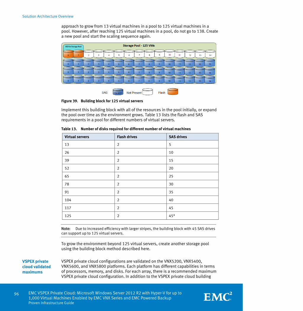
Solution Architecture Overview
96 EMC VSPEX Private Cloud: Microsoft Windows Server 2012 R2 with Hyper-V for up to 1,000 Virtual Machines Enabled by EMC VNX Series and EMC Powered Backup Proven Infrastructure Guide
approach to grow from 13 virtual machines in a pool to 125 virtual machines in a pool. However, after reaching 125 virtual machines in a pool, do not go to 138. Create a new pool and start the scaling sequence again.
Figure 39. Building block for 125 virtual servers
Implement this building block with all of the resources in the pool initially, or expand the pool over time as the environment grows. Table 13 lists the flash and SAS requirements in a pool for different numbers of virtual servers.
Table 13. Number of disks required for different number of virtual machines
Virtual servers Flash drives SAS drives
13 2 5
26 2 10
39 2 15
52 2 20
65 2 25
78 2 30
91 2 35
104 2 40
117 2 45
125 2 45*
Note: Due to increased efficiency with larger stripes, the building block with 45 SAS drives can support up to 125 virtual servers.
To grow the environment beyond 125 virtual servers, create another storage pool using the building block method described here.
VSPEX private cloud configurations are validated on the VNX5200, VNX5400, VNX5600, and VNX5800 platforms. Each platform has different capabilities in terms of processors, memory, and disks. For each array, there is a recommended maximum VSPEX private cloud configuration. In addition to the VSPEX private cloud building
VSPEX private cloud validated maximums

Solution Architecture Overview
EMC VSPEX Private Cloud: Microsoft Windows Server 2012 R2 with Hyper-V for up to 1,000 Virtual Machines Enabled by EMC VNX Series and EMC Powered Backup
Proven Infrastructure Guide
97
blocks, each storage array must contain the drives used for the VNX OE, and hot spare disks for the environment.
Notes:
Allocate at least one hot spare for every 30 disks of a given type and size.
The pool does not use system drives for additional storage.
If required, substitute larger drives for more capacity. To meet the load recommendations, all drives in the storage pool must be 15k RPM and the same size. Storage layout algorithms may produce sub-optimal results with drives of different sizes.
For all VSPEX private cloud solutions:
Enable FAST VP to automatically tier data to use differences in performance and capacity. FAST VP :
Works at the block storage pool level and automatically adjusts where data is stored based on access frequency.
Promotes frequently-accessed data to higher tiers of storage in 256 MB increments, and migrates infrequently-accessed data to a lower tier for cost efficiency. This rebalancing of 256 MB data units, or slices, is part of a regularly scheduled maintenance operation.
For block storage, allocate at least two LUNs to the Windows cluster from a single storage pool to serve as Cluster Shared Volumes for the virtual servers.
For file storage, allocate at least two CIFS shares to the Windows cluster from a single storage pool to serve as SMB shares for the virtual servers.
Optionally configure flash drives as FAST Cache in the array. LUNs or storage pools where virtual machines reside that have a higher than average I/O requirement can benefit from the FAST Cache feature. These drives are an optional part of the solution, and additional licenses may be required to use the FAST Suite.

Solution Architecture Overview
98 EMC VSPEX Private Cloud: Microsoft Windows Server 2012 R2 with Hyper-V for up to 1,000 Virtual Machines Enabled by EMC VNX Series and EMC Powered Backup Proven Infrastructure Guide
VNX5200
The VNX5200 is validated for up to 200 virtual servers. Figure 40 shows a typical configuration.
Figure 40. Storage layout for 200 virtual machines using VNX5200
This configuration uses the following storage layout:
Seventy-five 600 GB SAS drives are allocated to two block-based storage pools: one RAID-5 (4+1) pool with 45 SAS disks for 125 virtual machines and one RAID-5 (4+1) pool with 30 SAS disks for 75 virtual machines.
Note: To meet the load recommendations, all drives in the storage pool must be 15k rpm and the same size. Storage layout algorithms may produce sub-optimal results with drives of different sizes.
Four 200 GB flash drives are configured for Fast VP, two for each pool configured as RAID 1/0.
Three 600 GB SAS drives are configured as hot spares.
One 200 GB flash drive is configured as a hot spare.
Enable FAST VP to automatically tier data to leverage differences in performance and capacity.
FAST VP:
Works at the block storage pool level and automatically adjusts where data is stored based on how frequently it is accessed.
Promotes frequently accessed data to higher tiers of storage in 256-MB increments and migrates infrequently accessed data to a lower tier for cost efficiency. This rebalancing of 256 MB data units, or slices, is part of a regularly scheduled maintenance operation.
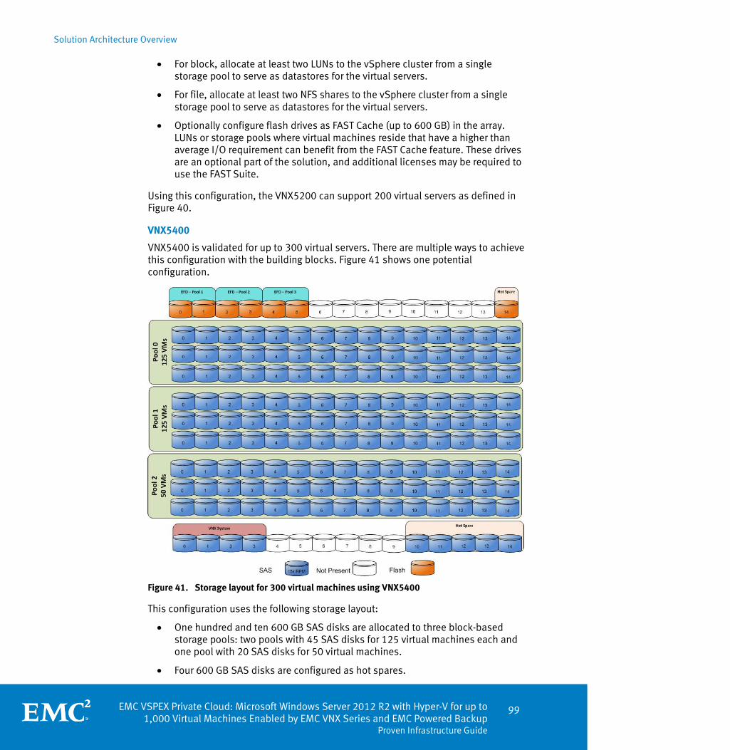
Solution Architecture Overview
EMC VSPEX Private Cloud: Microsoft Windows Server 2012 R2 with Hyper-V for up to 1,000 Virtual Machines Enabled by EMC VNX Series and EMC Powered Backup
Proven Infrastructure Guide
99
For block, allocate at least two LUNs to the vSphere cluster from a single storage pool to serve as datastores for the virtual servers.
For file, allocate at least two NFS shares to the vSphere cluster from a single storage pool to serve as datastores for the virtual servers.
Optionally configure flash drives as FAST Cache (up to 600 GB) in the array. LUNs or storage pools where virtual machines reside that have a higher than average I/O requirement can benefit from the FAST Cache feature. These drives are an optional part of the solution, and additional licenses may be required to use the FAST Suite.
Using this configuration, the VNX5200 can support 200 virtual servers as defined in Figure 40.
VNX5400
VNX5400 is validated for up to 300 virtual servers. There are multiple ways to achieve this configuration with the building blocks. Figure 41 shows one potential configuration.
Figure 41. Storage layout for 300 virtual machines using VNX5400
This configuration uses the following storage layout:
One hundred and ten 600 GB SAS disks are allocated to three block-based storage pools: two pools with 45 SAS disks for 125 virtual machines each and one pool with 20 SAS disks for 50 virtual machines.
Four 600 GB SAS disks are configured as hot spares.

Solution Architecture Overview
100 EMC VSPEX Private Cloud: Microsoft Windows Server 2012 R2 with Hyper-V for up to 1,000 Virtual Machines Enabled by EMC VNX Series and EMC Powered Backup Proven Infrastructure Guide
Six 200 GB flash drives are configured for Fast VP, two for each pool.
One 200 GB flash drive is allocated as a hot spare.
Using this configuration, the VNX5400 can support 300 virtual servers as defined in the Reference workload.

Solution Architecture Overview
EMC VSPEX Private Cloud: Microsoft Windows Server 2012 R2 with Hyper-V for up to 1,000 Virtual Machines Enabled by EMC VNX Series and EMC Powered Backup
Proven Infrastructure Guide
101
VNX5600
VNX5600 has been validated for up to 600 virtual servers. There are multiple ways to achieve this configuration with the building block approach. Figure 42 shows one potential configuration.
Figure 42. Storage layout for 600 virtual machines using VNX5600
This configuration uses the following storage layout:
Two hundred and twenty 600 GB SAS disks are allocated to five block-based storage pools: four pools with 45 SAS disks for 125 virtual machines each and one pool with 40 SAS disks for 100 virtual machines.
Eight 600 GB SAS disks are configured as hot spares.

Solution Architecture Overview
102 EMC VSPEX Private Cloud: Microsoft Windows Server 2012 R2 with Hyper-V for up to 1,000 Virtual Machines Enabled by EMC VNX Series and EMC Powered Backup Proven Infrastructure Guide
Ten 200 GB flash drives are configured for Fast VP, two for each pool
One 200 GB flash drive is allocated as a hot spare.
Using this configuration, the VNX5600 can support 600 virtual servers as defined in Reference workload.
VNX5800
VNX5800 is validated for up to 1,000 virtual servers. There are multiple ways to achieve this configuration with the building blocks. Figure 43 shows one potential configuration.
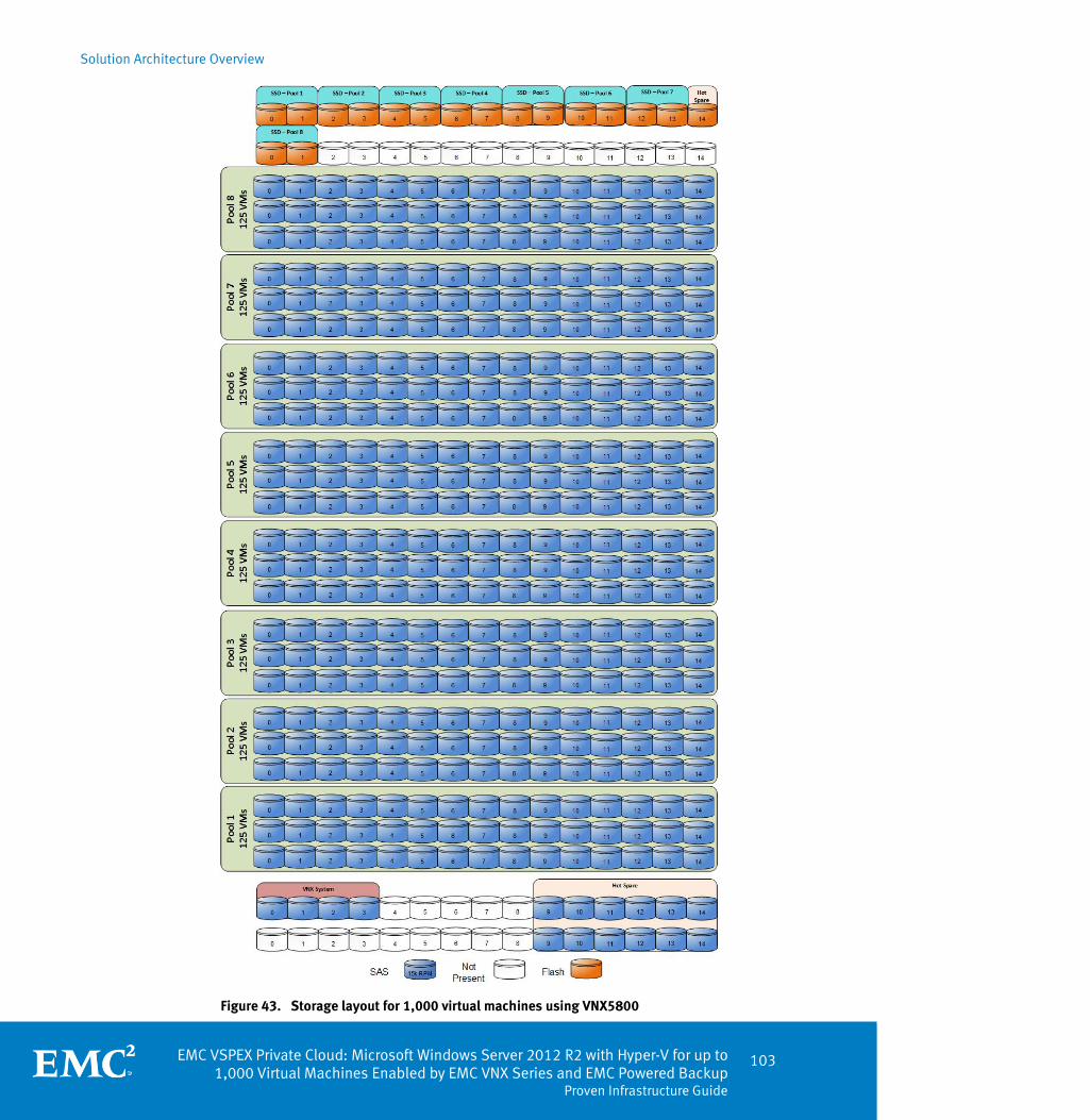
Solution Architecture Overview
EMC VSPEX Private Cloud: Microsoft Windows Server 2012 R2 with Hyper-V for up to 1,000 Virtual Machines Enabled by EMC VNX Series and EMC Powered Backup
Proven Infrastructure Guide
103
Figure 43. Storage layout for 1,000 virtual machines using VNX5800

Solution Architecture Overview
104 EMC VSPEX Private Cloud: Microsoft Windows Server 2012 R2 with Hyper-V for up to 1,000 Virtual Machines Enabled by EMC VNX Series and EMC Powered Backup Proven Infrastructure Guide
This configuration uses the following storage layout:
Three hundred and sixty 600 GB SAS disks are allocated to eight block-based storage pools: each with 45 SAS disks for 125 virtual machines.
Twelve 600 GB SAS disks are configured as hot spares.
Sixteen 200 GB flash drives are configured for Fast VP, two for each pool.
One 200 GB flash drive is allocated as a hot spare.
Using this configuration, the VNX5800 can support 1,000 virtual servers as defined in the Reference workload.
Conclusion
The scale levels listed in Figure 44 highlight the entry points and supported maximums for the arrays in the VSPEX private cloud environment. The entry points represent optimal model demarcations in terms of the number of virtual machines within the environment. This aids in providing a frame of reference to determine which VNX array to choose based upon your requirements. It is acceptable to configure any of the listed arrays with a smaller number of virtual machines than the maximums supported using the building block approach described earlier.
Figure 44. Maximum scale levels and entry points of different arrays

Solution Architecture Overview
EMC VSPEX Private Cloud: Microsoft Windows Server 2012 R2 with Hyper-V for up to 1,000 Virtual Machines Enabled by EMC VNX Series and EMC Powered Backup
Proven Infrastructure Guide
105
High-availability and failover
This VSPEX solution provides a highly available virtualized server, network, and storage infrastructure. When implemented in accordance with this guide, it provides the ability to survive single-unit failures with little or no impact on business operations.
Configure high availability in the virtualization layer, and configure the hypervisor to automatically restart failed virtual machines. Figure 45 illustrates the hypervisor layer responding to a failure in the compute layer.
Figure 45. High availability at the virtualization layer
By implementing high availability at the virtualization layer, even in a hardware failure, the infrastructure attempts to keep as many services running as possible.
While the choice of servers to implement in the compute layer is flexible, use enterprise class servers designed for the data center. This type of server has redundant power supplies, as shown in Figure 46. Connect the servers to separate power distribution units (PDUs) in accordance with your server vendor’s best practices.
Figure 46. Redundant power supplies
Overview
Virtualization layer
Compute layer
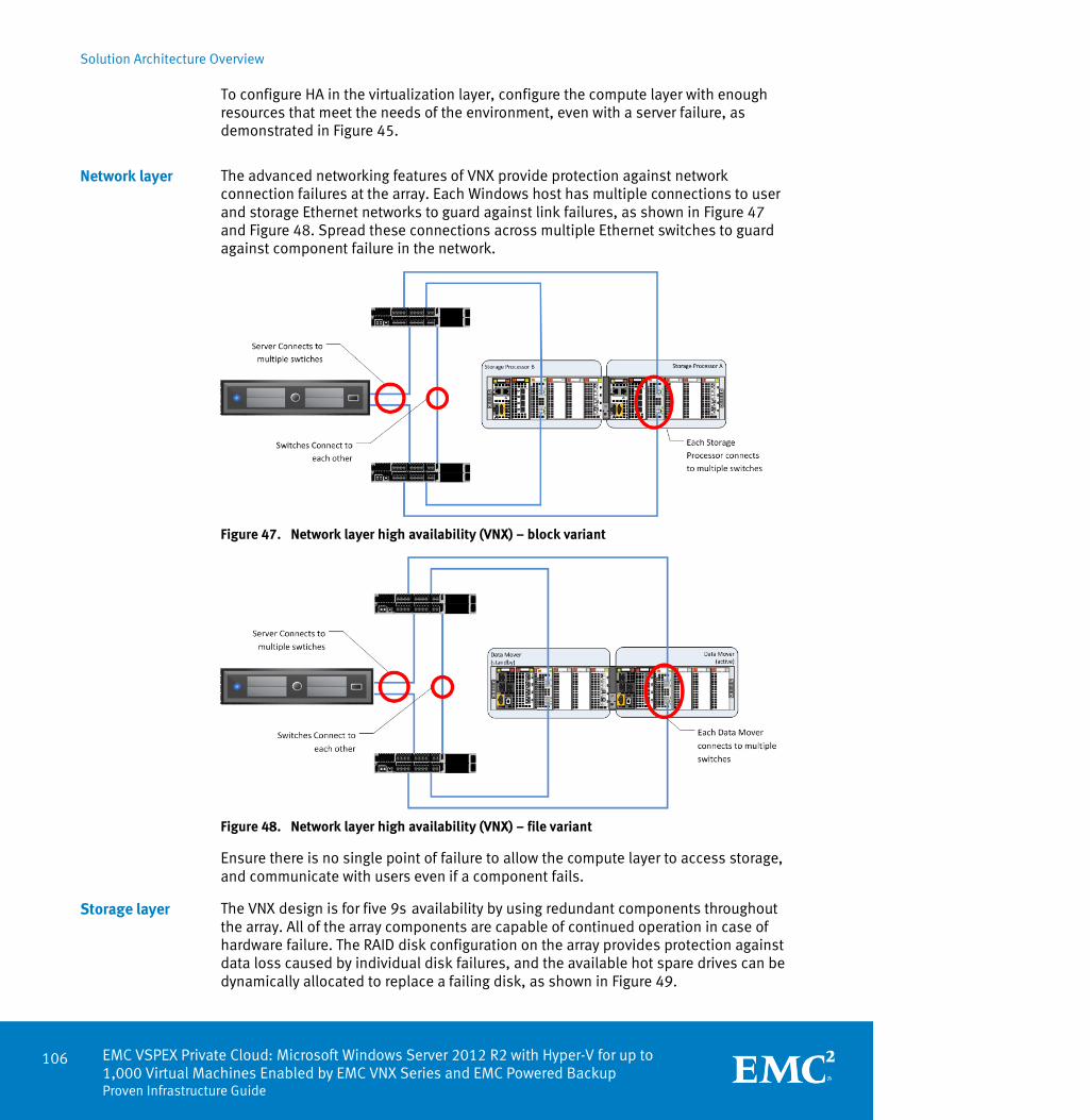
Solution Architecture Overview
106 EMC VSPEX Private Cloud: Microsoft Windows Server 2012 R2 with Hyper-V for up to 1,000 Virtual Machines Enabled by EMC VNX Series and EMC Powered Backup Proven Infrastructure Guide
To configure HA in the virtualization layer, configure the compute layer with enough resources that meet the needs of the environment, even with a server failure, as demonstrated in Figure 45.
The advanced networking features of VNX provide protection against network connection failures at the array. Each Windows host has multiple connections to user and storage Ethernet networks to guard against link failures, as shown in Figure 47 and Figure 48. Spread these connections across multiple Ethernet switches to guard against component failure in the network.
Figure 47. Network layer high availability (VNX) – block variant
Figure 48. Network layer high availability (VNX) – file variant
Ensure there is no single point of failure to allow the compute layer to access storage, and communicate with users even if a component fails.
The VNX design is for five 9s availability by using redundant components throughout the array. All of the array components are capable of continued operation in case of hardware failure. The RAID disk configuration on the array provides protection against data loss caused by individual disk failures, and the available hot spare drives can be dynamically allocated to replace a failing disk, as shown in Figure 49.
Network layer
Storage layer

Solution Architecture Overview
EMC VSPEX Private Cloud: Microsoft Windows Server 2012 R2 with Hyper-V for up to 1,000 Virtual Machines Enabled by EMC VNX Series and EMC Powered Backup
Proven Infrastructure Guide
107
Figure 49. VNX series HA components
EMC storage arrays support HA by default. When configured according to the directions in their installation guides, no single unit failures result in data loss or unavailability.
Validation test profile
The VSPEX solution was validated with the environment profile described in Table 14.
Table 14. Profile characteristics
Profile characteristic Value
Number of virtual machines 200/300/600/1,000
Virtual machine OS Windows Server 2012 Datacenter Edition
Processors per virtual machine 1
Number of virtual processors per physical CPU core 4
RAM per virtual machine 2 GB
Average storage available for each virtual machine 100 GB
Average IOPS per virtual machine 25 IOPS
Number of LUNs or CIFS shares to store virtual machine disks
6/10/16
Profile characteristics
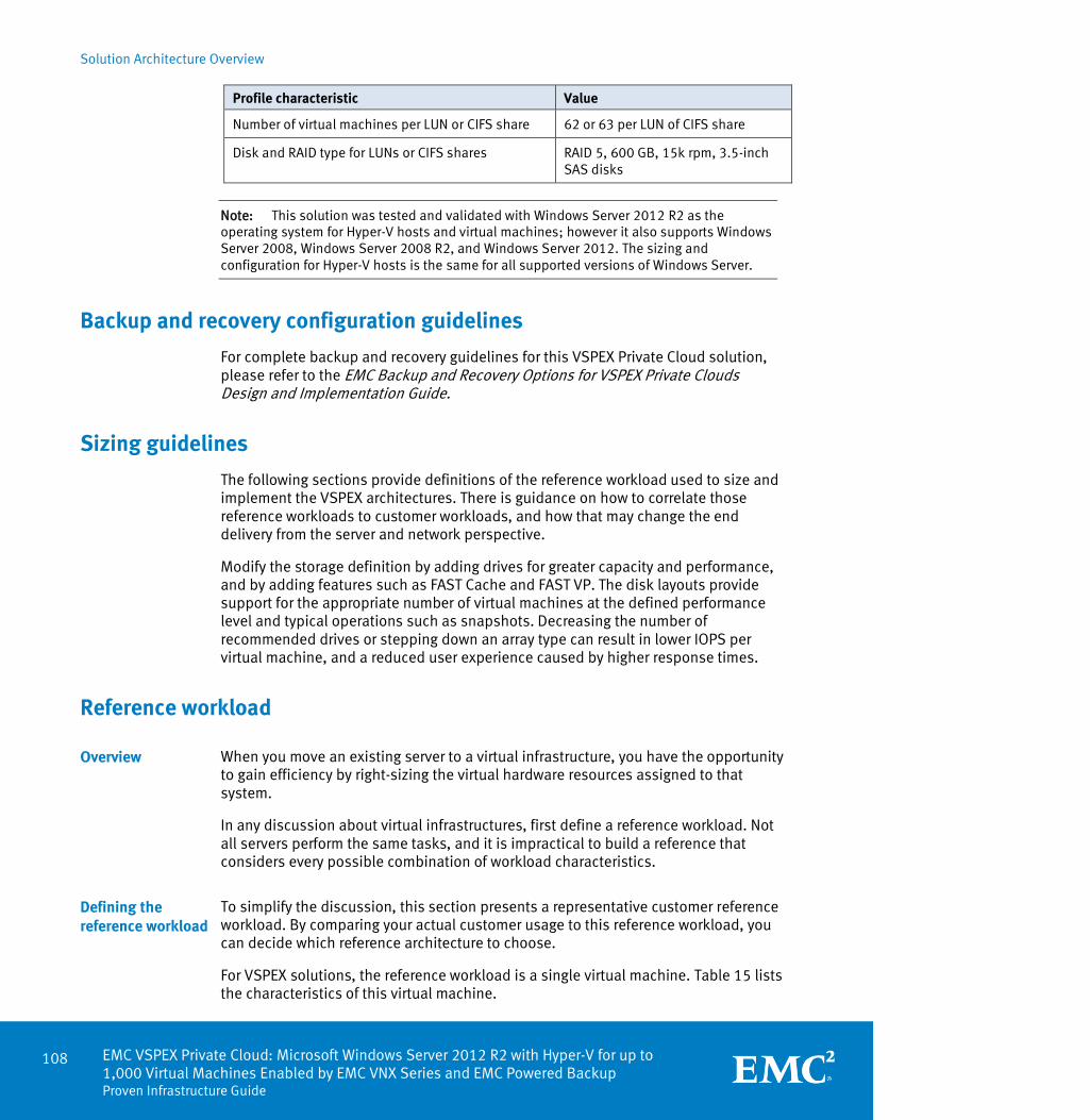
Solution Architecture Overview
108 EMC VSPEX Private Cloud: Microsoft Windows Server 2012 R2 with Hyper-V for up to 1,000 Virtual Machines Enabled by EMC VNX Series and EMC Powered Backup Proven Infrastructure Guide
Profile characteristic Value
Number of virtual machines per LUN or CIFS share 62 or 63 per LUN of CIFS share
Disk and RAID type for LUNs or CIFS shares RAID 5, 600 GB, 15k rpm, 3.5-inch SAS disks
Note: This solution was tested and validated with Windows Server 2012 R2 as the operating system for Hyper-V hosts and virtual machines; however it also supports Windows Server 2008, Windows Server 2008 R2, and Windows Server 2012. The sizing and configuration for Hyper-V hosts is the same for all supported versions of Windows Server.
Backup and recovery configuration guidelines
For complete backup and recovery guidelines for this VSPEX Private Cloud solution, please refer to the EMC Backup and Recovery Options for VSPEX Private Clouds Design and Implementation Guide.
Sizing guidelines
The following sections provide definitions of the reference workload used to size and implement the VSPEX architectures. There is guidance on how to correlate those reference workloads to customer workloads, and how that may change the end delivery from the server and network perspective.
Modify the storage definition by adding drives for greater capacity and performance, and by adding features such as FAST Cache and FAST VP. The disk layouts provide support for the appropriate number of virtual machines at the defined performance level and typical operations such as snapshots. Decreasing the number of recommended drives or stepping down an array type can result in lower IOPS per virtual machine, and a reduced user experience caused by higher response times.
Reference workload
When you move an existing server to a virtual infrastructure, you have the opportunity to gain efficiency by right-sizing the virtual hardware resources assigned to that system.
In any discussion about virtual infrastructures, first define a reference workload. Not all servers perform the same tasks, and it is impractical to build a reference that considers every possible combination of workload characteristics.
To simplify the discussion, this section presents a representative customer reference workload. By comparing your actual customer usage to this reference workload, you can decide which reference architecture to choose.
For VSPEX solutions, the reference workload is a single virtual machine. Table 15 lists the characteristics of this virtual machine.
Overview
Defining the reference workload

Solution Architecture Overview
EMC VSPEX Private Cloud: Microsoft Windows Server 2012 R2 with Hyper-V for up to 1,000 Virtual Machines Enabled by EMC VNX Series and EMC Powered Backup
Proven Infrastructure Guide
109
Table 15. Virtual machine characteristics
Characteristic Value
Virtual machine operating system Microsoft Windows Server 2012 R2 Datacenter Edition
Virtual processors per virtual machine 1
RAM per virtual machine 2 GB
Available storage capacity per virtual machine 100 GB
I/O operations per second (IOPS) per virtual machine
25
I/O pattern Random
I/O read/write ratio 2:1
This specification for a virtual machine does not represent any specific application. Rather, it represents a single common point of reference to measure other virtual machines.
Server processor capabilities are constantly evolving. Server providers aligned with the VSPEX program may specify updated compute expectations based on recent technology changes. This guidance may override the compute requirements specified in the reference workload.
Applying the reference workload
The solution creates a pool of resources that are sufficient to host a target number of reference virtual machines with the characteristics shown in Table 15. The customer virtual machines may not exactly match the specifications. In that case, define a single specific customer virtual machine as the equivalent of some number of reference virtual machines together, and assume these virtual machines are in use in the pool. Continue to provision virtual machines from the resource pool until no resources remain.
A small custom-built application server must move into this virtual infrastructure. The physical hardware that supports the application is not fully utilized. A careful analysis of the existing application reveals that the application can use one processor, and needs 3 GB memory to run normally. The I/O workload ranges between 4 IOPS at idle time to a peak of 15 IOPS when busy. The entire application consumes about 30 GB on local hard drive storage.
Based on these numbers, the resource pool needs the following resources:
CPU of one reference virtual machine
Memory of two reference virtual machines
Storage of one reference virtual machine
I/Os of one reference virtual machine
Overview
Example 1: Custom-built application

Solution Architecture Overview
110 EMC VSPEX Private Cloud: Microsoft Windows Server 2012 R2 with Hyper-V for up to 1,000 Virtual Machines Enabled by EMC VNX Series and EMC Powered Backup Proven Infrastructure Guide
In this example, an appropriate virtual machine uses the resources for two of the reference virtual machines. If implemented on a VNX5400 storage system which can support up to 300 virtual machines, resources for 298 reference virtual machines remain.
The database server for a customer’s Point-of-Sale system must move into this virtual infrastructure. It is currently running on a physical system with four CPUs and 16 GB memory. It uses 200 GB storage and generates 200 IOPS during an average busy cycle.
The requirements to virtualize this application are:
CPUs of four reference virtual machines
Memory of eight reference virtual machines
Storage of two reference virtual machines
I/Os of eight reference virtual machines
In this case, the one appropriate virtual machine uses the resources of eight reference virtual machines. If implemented on a VNX5400 storage system which can support up to 300 virtual machines, resources for 292 reference virtual machines remain.
The customer’s web server must move into this virtual infrastructure. It is currently running on a physical system with two CPUs and 8 GB memory. It uses 25 GB storage and generates 50 IOPS during an average busy cycle.
The requirements to virtualize this application are:
CPUs of two reference virtual machines
Memory of four reference virtual machines
Storage of one reference virtual machine
I/Os of two reference virtual machines
In this case, the one appropriate virtual machine uses the resources of four reference virtual machines. If implemented on a VNX5400 storage system which can support up to 300 virtual machines, resources for 296 reference virtual machines remain.
The database server for a customer’s decision support system must move into this virtual infrastructure. It is currently running on a physical system with 10 CPUs and 64 GB memory. It uses 5 TB storage and generates 700 IOPS during an average busy cycle.
The requirements to virtualize this application are:
CPUs of 10 reference virtual machines
Memory of 32 reference virtual machines
Storage of 52 reference virtual machines
Example 2: Point-of-Sale system
Example 3: Web server
Example 4: Decision-support database

Solution Architecture Overview
EMC VSPEX Private Cloud: Microsoft Windows Server 2012 R2 with Hyper-V for up to 1,000 Virtual Machines Enabled by EMC VNX Series and EMC Powered Backup
Proven Infrastructure Guide
111
I/Os of 28 reference virtual machines
In this case, one virtual machine uses the resources of 52 reference virtual machines. If implemented on a VNX5400 storage system which can support up to 300 virtual machines, resources for 248 reference virtual machines remain.
These four examples illustrate the flexibility of the resource pool model. In all four cases, the workloads reduce the amount of available resources in the pool. All four examples can be implemented on the same virtual infrastructure with an initial capacity for 300 reference virtual machines, and resources for 234 reference virtual machines remain in the resource pool as shown in Figure 50.
Figure 50. Resource pool flexibility
In more advanced cases, there may be tradeoffs between memory and I/O or other relationships where increasing the amount of one resource decreases the need for another. In these cases, the interactions between resource allocations become highly complex, and are beyond the scope of the document. Examine the change in resource balance and determine the new level of requirements. Add these virtual machines to the infrastructure with the method described in the examples.
Implementing the solution
The solution described in this guide requires a set of hardware to be available for the CPU, memory, network, and storage needs of the system. These are general requirements that are independent of any particular implementation except that the requirements grow linearly with the target level of scale. This section describes some considerations for implementing the requirements.
The solution defines the hardware requirements for the solution in terms of these basic resources:
CPU resources
Memory resources
Network resources
Storage resources
This section describes the resource types, their use in the solution, and key implementation considerations in a customer environment.
The solution defines the number of CPU cores that are required, but not a specific type or configuration. New deployments should use recent revisions of common
Summary of examples
Overview
Resource types
CPU resources

Solution Architecture Overview
112 EMC VSPEX Private Cloud: Microsoft Windows Server 2012 R2 with Hyper-V for up to 1,000 Virtual Machines Enabled by EMC VNX Series and EMC Powered Backup Proven Infrastructure Guide
processor technologies. It is assumed that these perform as well as, or better than, the systems used to validate the solution.
In any running system, monitor the utilization of resources and adapt as needed. The reference virtual machine and required hardware resources in the solution assume that there are four virtual CPUs for each physical processor core (4:1 ratio). Usually, this provides an appropriate level of resources for the hosted virtual machines; however, this ratio may not be appropriate in all use cases. Monitor the CPU utilization at the hypervisor layer to determine if more resources are required.
Each virtual server in the solution must have 2 GB of memory. In a virtual environment, it is common to provision virtual machines with more memory than is installed on the physical hypervisor server because of budget constraints. Memory over-commitment assumes that each virtual machine does not use all its allocated memory. To oversubscribe the memory usage to some degree makes business sense. The administrator has the responsibility to proactively monitor the oversubscription rate such that it does not shift the bottleneck away from the server and become a burden to the storage subsystem via page file swapping.
This solution is validated with statically assigned memory and no over-commitment of memory resources. If a real-world environment uses over-committed memory, monitor the system memory utilization and associated page file I/O activity consistently to ensure that a memory shortfall does not cause unexpected results.
The solution outlines the minimum needs of the system. If the system requires additional bandwidth, add capability at both the storage array and the hypervisor host to meet the requirements. The options for network connectivity on the server depend on the type of server. The storage arrays have a number of included network ports, and can add ports using EMC UltraFlex I/O modules.
For reference purposes in the validated environment, each virtual machine generates 25 IOPS with an average size of 8 KB. This means that each virtual machine is generating at least 200 KB/s traffic on the storage network. For an environment rated for 300 virtual machines, this comes out to a minimum of approximately 60 MB/sec. This is well within the bounds of modern networks. However, this does not consider other operations. For example, additional bandwidth is needed for:
User network traffic
Virtual machine migration
Administrative and management operations
The requirements for each of these depend on the use of the environment. It is not practical to provide precise numbers in this context. However, the network described in the solution should be sufficient to handle average workloads for the above use cases.
Regardless of the network traffic requirements, always have at least two physical network connections shared for a logical network so that a single link failure does not affect the availability of the system. Design the network so that the aggregate bandwidth in the event of a failure is sufficient to accommodate the full workload.
Memory resources
Network resources

Solution Architecture Overview
EMC VSPEX Private Cloud: Microsoft Windows Server 2012 R2 with Hyper-V for up to 1,000 Virtual Machines Enabled by EMC VNX Series and EMC Powered Backup
Proven Infrastructure Guide
113
The storage building blocks described in this solution contain layouts for the disks used in the system validation. Each layout balances the available storage capacity with the performance capability of the drives. Consider a few factors when examining storage sizing. Specifically, the array has a collection of disks assigned to a storage pool. From that storage pool, provision CIFS shares to the Windows cluster. Each layer has a specific configuration that is defined for the solution and documented in Chapter 5.
It is acceptable to replace drives with larger capacity drives of the same type and performance characteristics, or with higher performance drives of the same type and capacity. Similarly, it is acceptable to change the placement of drives in the drive shelves in order to comply with updated or new drive shelf arrangements. Moreover, it is acceptable to scale up using the building blocks with larger numbers of drives up to the limit defined in the VSPEX private cloud validated maximums. Observe the following best practices:
Use the latest best practices guidance from EMC regarding drive placement within the shelf. Refer to Applied Best Practices Guide: EMC VNX Unified Best Practices for Performance.
When expanding the capability of a storage pool using the building blocks described in this document, use the same type and size of drive in the pool. Create a new pool to use different drive types and sizes. This prevents uneven performance across the pool.
Configure at least one hot spare for every type and size of drive on the system.
Configure at least one hot spare for every 30 drives of a given type.
In other cases where there is a need to deviate from the proposed number and type of drives specified, or the specified pool and datastore layouts, ensure that the target layout delivers the same or greater resources to the system and conforms to EMC published best practices.
The requirements in the reference architecture are what EMC considers the minimum set of resources to handle the workloads required based on the stated definition of a reference virtual machine. In any customer implementation, the load of a system varies over time as users interact with the system. However, if the customer virtual machines differ significantly from the reference definition, and vary in the same resource group, add more of that resource type to the system to compensate.
Storage resources
Implementation summary
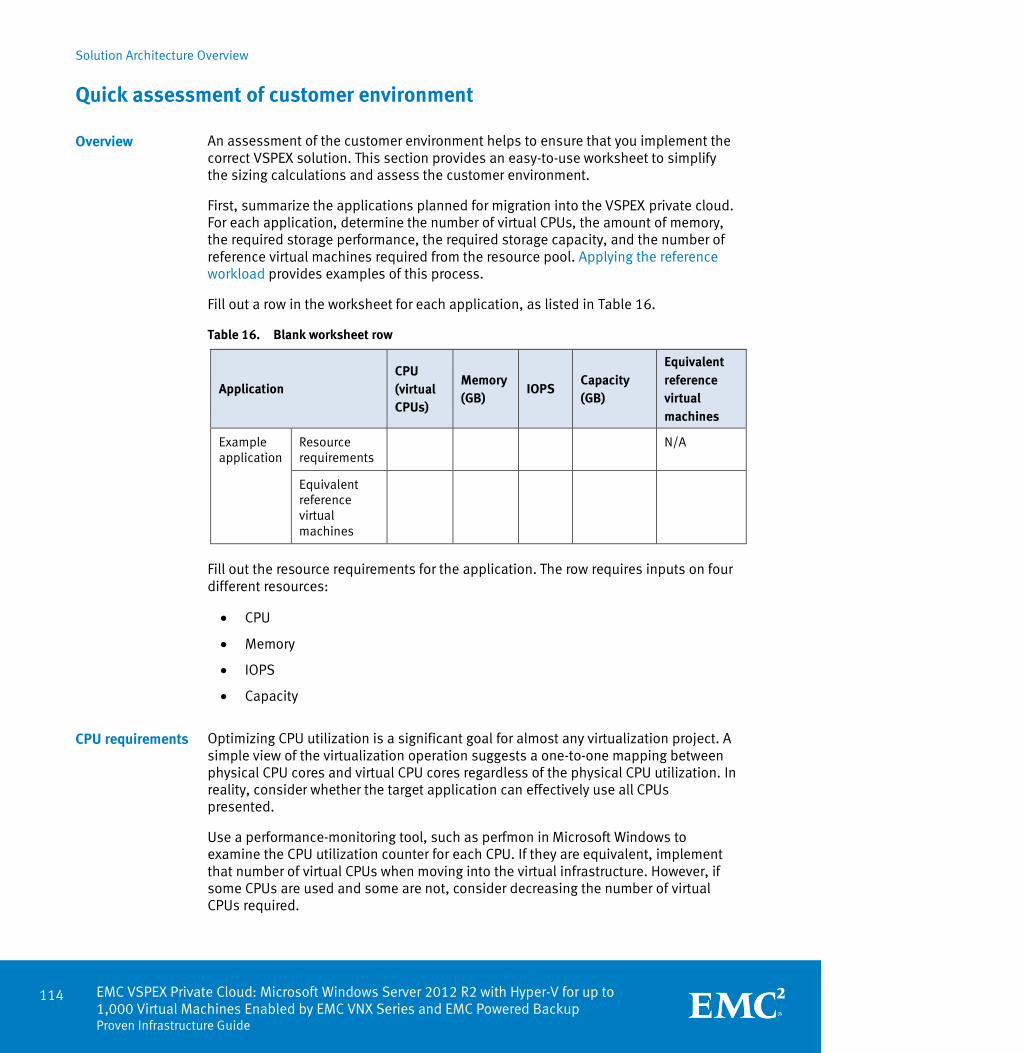
Solution Architecture Overview
114 EMC VSPEX Private Cloud: Microsoft Windows Server 2012 R2 with Hyper-V for up to 1,000 Virtual Machines Enabled by EMC VNX Series and EMC Powered Backup Proven Infrastructure Guide
Quick assessment of customer environment
An assessment of the customer environment helps to ensure that you implement the correct VSPEX solution. This section provides an easy-to-use worksheet to simplify the sizing calculations and assess the customer environment.
First, summarize the applications planned for migration into the VSPEX private cloud. For each application, determine the number of virtual CPUs, the amount of memory, the required storage performance, the required storage capacity, and the number of reference virtual machines required from the resource pool. Applying the reference workload provides examples of this process.
Fill out a row in the worksheet for each application, as listed in Table 16.
Table 16. Blank worksheet row
Application CPU (virtual CPUs)
Memory (GB)
IOPS Capacity (GB)
Equivalent reference virtual machines
Example application
Resource requirements
N/A
Equivalent reference virtual machines
Fill out the resource requirements for the application. The row requires inputs on four different resources:
CPU
Memory
IOPS
Capacity
Optimizing CPU utilization is a significant goal for almost any virtualization project. A simple view of the virtualization operation suggests a one-to-one mapping between physical CPU cores and virtual CPU cores regardless of the physical CPU utilization. In reality, consider whether the target application can effectively use all CPUs presented.
Use a performance-monitoring tool, such as perfmon in Microsoft Windows to examine the CPU utilization counter for each CPU. If they are equivalent, implement that number of virtual CPUs when moving into the virtual infrastructure. However, if some CPUs are used and some are not, consider decreasing the number of virtual CPUs required.
Overview
CPU requirements

Solution Architecture Overview
EMC VSPEX Private Cloud: Microsoft Windows Server 2012 R2 with Hyper-V for up to 1,000 Virtual Machines Enabled by EMC VNX Series and EMC Powered Backup
Proven Infrastructure Guide
115
In any operation that involves performance monitoring, collect data samples for a period of time that includes all operational use cases of the system. Use either the maximum or 95th percentile value of the resource requirements for planning purposes.
Server memory plays a key role in ensuring application functionality and performance. Therefore, each server process has different targets for the acceptable amount of available memory. When moving an application into a virtual environment, consider the current memory available to the system and monitor the free memory by using a performance-monitoring tool, such as Microsoft Windows perfmon, to determine memory efficiency.
The storage performance requirements for an application are usually the least understood aspect of performance. Several components become important when discussing the I/O performance of a system. The first is the number of requests coming in – or IOPS. Equally important is the size of the request, or I/O size -- a request for 4 KB of data is easier and faster to process than a request for 4 MB of data. That distinction becomes important with the another factor, which is the average I/O response time, or I/O latency.
The reference virtual machine calls for 25 IOPS. To monitor this on an existing system, use a performance-monitoring tool such as Microsoft Windows perfmon. Perfmon provides several counters that can help. The most common are:
Logical Disk or Disk Transfer/sec
Logical Disk or Disk Reads/sec
Logical Disk or Disk Writes/sec
Note: At the time of publication, Windows perfmon does not provide counters to expose IOPS and latency for CIFS-based VHDX storage. Monitor these areas from the VNX array as discussed in Chapter 7.
The reference virtual machine assumes a 2:1 read: write ratio. Use these counters to determine the total number of IOPS, and the approximate ratio of reads to writes for the customer application.
The I/O size is important because smaller I/O requests are faster and easier to process than large I/O requests. The reference virtual machine assumes an average I/O request size of 8 KB, which is appropriate for a large range of applications. Most applications use I/O sizes that are even powers of 2, such as 4 KB, 8 KB, 16 KB, or 32 KB. The performance counter calculates a simple average; it is common to see 11 KB or 15 KB instead of the actual I/O sizes.
The reference virtual machine assumes an 8 KB I/O size. If the average customer I/O size is less than 8 KB, use the observed IOPS number. However, if the average I/O size is significantly higher, apply a scaling factor to account for the large I/O size. A safe estimate is to divide the I/O size by 8 KB and use that factor. For example, if the application is using mostly 32 KB I/O requests, use a factor of four (32 KB/8 KB = 4).
Memory requirements
Storage performance requirements
IOPS
I/O size
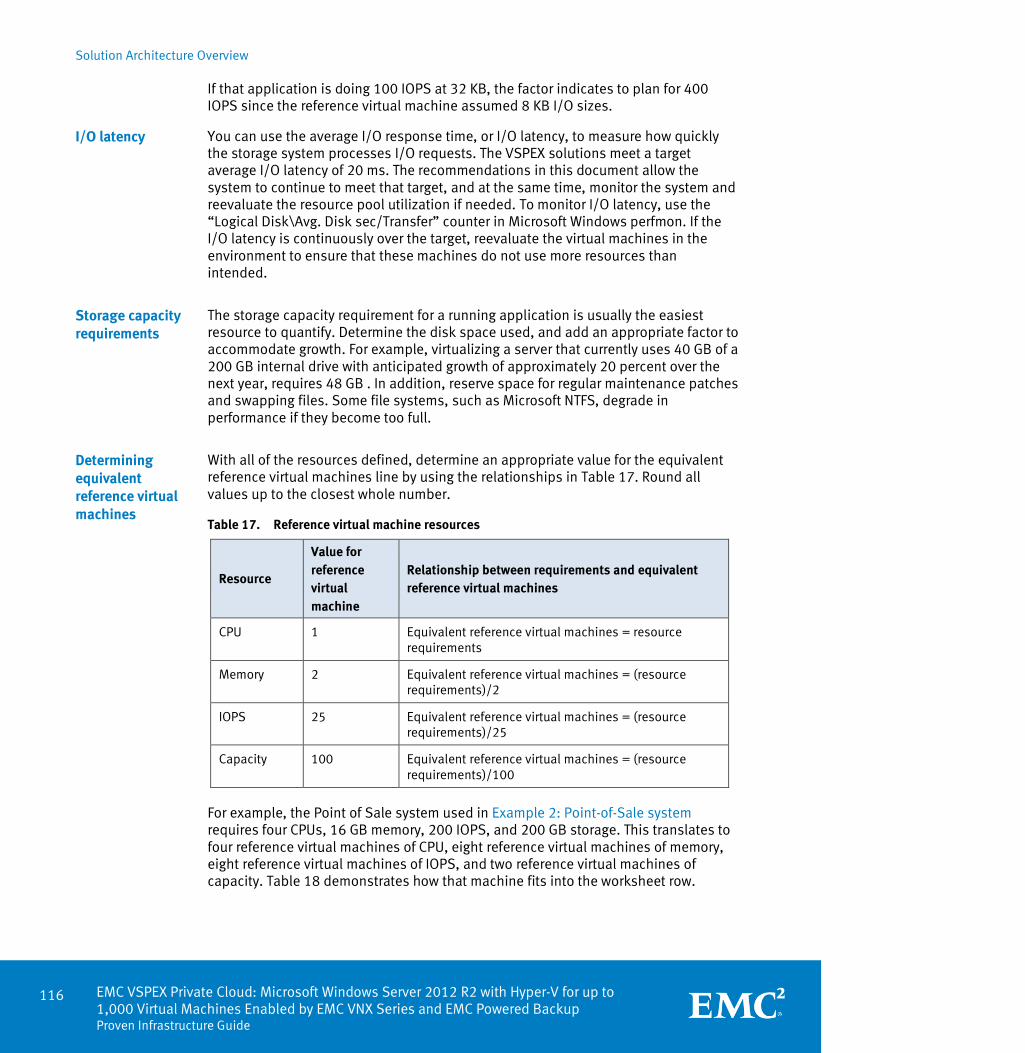
Solution Architecture Overview
116 EMC VSPEX Private Cloud: Microsoft Windows Server 2012 R2 with Hyper-V for up to 1,000 Virtual Machines Enabled by EMC VNX Series and EMC Powered Backup Proven Infrastructure Guide
If that application is doing 100 IOPS at 32 KB, the factor indicates to plan for 400 IOPS since the reference virtual machine assumed 8 KB I/O sizes.
You can use the average I/O response time, or I/O latency, to measure how quickly the storage system processes I/O requests. The VSPEX solutions meet a target average I/O latency of 20 ms. The recommendations in this document allow the system to continue to meet that target, and at the same time, monitor the system and reevaluate the resource pool utilization if needed. To monitor I/O latency, use the “Logical Disk\Avg. Disk sec/Transfer” counter in Microsoft Windows perfmon. If the I/O latency is continuously over the target, reevaluate the virtual machines in the environment to ensure that these machines do not use more resources than intended.
The storage capacity requirement for a running application is usually the easiest resource to quantify. Determine the disk space used, and add an appropriate factor to accommodate growth. For example, virtualizing a server that currently uses 40 GB of a 200 GB internal drive with anticipated growth of approximately 20 percent over the next year, requires 48 GB . In addition, reserve space for regular maintenance patches and swapping files. Some file systems, such as Microsoft NTFS, degrade in performance if they become too full.
With all of the resources defined, determine an appropriate value for the equivalent reference virtual machines line by using the relationships in Table 17. Round all values up to the closest whole number.
Table 17. Reference virtual machine resources
Resource
Value for reference virtual machine
Relationship between requirements and equivalent reference virtual machines
CPU 1 Equivalent reference virtual machines = resource requirements
Memory 2 Equivalent reference virtual machines = (resource requirements)/2
IOPS 25 Equivalent reference virtual machines = (resource requirements)/25
Capacity 100 Equivalent reference virtual machines = (resource requirements)/100
For example, the Point of Sale system used in Example 2: Point-of-Sale system requires four CPUs, 16 GB memory, 200 IOPS, and 200 GB storage. This translates to four reference virtual machines of CPU, eight reference virtual machines of memory, eight reference virtual machines of IOPS, and two reference virtual machines of capacity. Table 18 demonstrates how that machine fits into the worksheet row.
I/O latency
Storage capacity requirements
Determining equivalent reference virtual machines

Solution Architecture Overview
EMC VSPEX Private Cloud: Microsoft Windows Server 2012 R2 with Hyper-V for up to 1,000 Virtual Machines Enabled by EMC VNX Series and EMC Powered Backup
Proven Infrastructure Guide
117
Table 18. Example worksheet row
Application
CPU
(virtual CPUs)
Memory (GB)
IOPS Capacity (GB)
Equivalent reference virtual machines
Example application
Resource requirements
4 16 200 200 N/A
Equivalent reference virtual machines
4 8 8 2 8
Use the highest value in the row to fill in the Equivalent reference virtual machines column. As shown in Figure 51, the example requires eight reference virtual machines.
Figure 51. Required resource from the reference virtual machine pool
Implementation example – stage 1
A customer wants to build a virtual infrastructure to support one custom-built application, one Point of Sale system, and one web server. The customer computes the sum of the Equivalent reference virtual machines column on the right side of the worksheet as listed in Table 19 to calculate the total number of reference virtual machines required. The table shows the result of the calculation, along with the value, rounded up to the nearest whole number.

Solution Architecture Overview
118 EMC VSPEX Private Cloud: Microsoft Windows Server 2012 R2 with Hyper-V for up to 1,000 Virtual Machines Enabled by EMC VNX Series and EMC Powered Backup Proven Infrastructure Guide
Table 19. Example applications – stage 1
Server resources Storage resources
Application CPU
(virtual CPUs)
Memory (GB)
IOPS Capacity (GB)
Reference virtual machines
Example application #1: Custom built application
Resource requirements
1 3 15 30 N/A
Equivalent reference virtual machines
1 2 1 1 2
Example Application #2: Point of sale system
Resource requirements
4 16 200 200 N/A
Equivalent reference virtual machines
4 8 8 2 8
Example Application #3: Web server
Resource requirements
2 8 50 25 N/A
Equivalent reference virtual machines
2 4 2 1 4
Total equivalent reference virtual machines 14
This example requires 14 reference virtual machines. According to the sizing guidelines, one storage pool with 10 SAS drives and 2 or more flash drives provides sufficient resources for the current needs and room for growth. You can implement this storage layout with VNX5400, for up to 300 reference virtual machines.
Figure 52 shows 12 reference virtual machines are available after implementing VNX5400 with 10 SAS drives and two flash drives.

Solution Architecture Overview
EMC VSPEX Private Cloud: Microsoft Windows Server 2012 R2 with Hyper-V for up to 1,000 Virtual Machines Enabled by EMC VNX Series and EMC Powered Backup
Proven Infrastructure Guide
119
Figure 52. Aggregate resource requirements – stage 1
Figure 53 shows the pool configuration in this example.
Figure 53. Pool configuration – stage 1

Solution Architecture Overview
120 EMC VSPEX Private Cloud: Microsoft Windows Server 2012 R2 with Hyper-V for up to 1,000 Virtual Machines Enabled by EMC VNX Series and EMC Powered Backup Proven Infrastructure Guide
Implementation example – stage 2
This customer must add a decision support database to this virtual infrastructure. Using the same strategy, calculate the number of Equivalent reference virtual machines required, as shown in Table 20.
Table 20. Example applications - stage 2
Server resources Storage resources
Application CPU
(virtual CPUs)
Memory (GB)
IOPS Capacity (GB)
Reference virtual machines
Example application #1: Custom built application
Resource requirements
1 3 15 30 N/A
Equivalent reference virtual machines
1 2 1 1 2
Example application #2: Point of Sale system
Resource requirements
4 16 200 200 N/A
Equivalent reference virtual machines
4 8 8 2 8
Example application #3:Web server
Resource requirements
2 8 50 25 N/A
Equivalent reference virtual machines
2 4 4 1 4
Example application #4: Decision support database
Resource requirements
10 64 700 5,120 N/A
Equivalent reference virtual machines
10 32 28 52 52
Total equivalent reference virtual machines 66
This example requires 66 reference virtual machines. According to the sizing guidelines, one storage pool with 30 SAS drives and two or more flash drives provides sufficient resources for the current needs and room for growth. You can implement this storage layout with VNX5400, for up to 300 reference virtual machines.
Figure 54 shows 12 reference virtual machines available after implementing VNX5400 with 30 SAS drives and two flash drives.

Solution Architecture Overview
EMC VSPEX Private Cloud: Microsoft Windows Server 2012 R2 with Hyper-V for up to 1,000 Virtual Machines Enabled by EMC VNX Series and EMC Powered Backup
Proven Infrastructure Guide
121
Figure 54. Aggregate resource requirements - stage 2
Figure 55 shows the pool configuration in this example.
Figure 55. Pool configuration – stage 2
Implementation example – stage 3
With business growth, the customer must implement a much larger virtual environment to support one custom built application, one Point of Sale system, two web servers, and three Decision Support System databases. Using the same strategy, calculate the number of Equivalent reference virtual machines, as shown in Table 21.
Table 21. Example applications - stage 3
Server resources Storage resources
Application CPU
(virtual CPUs)
Memory (GB)
IOPS Capacity (GB)
Reference virtual machines
Example application #1: Custom built application
Resource requirements
1 3 15 30 N/A
Equivalent reference virtual machines
1 2 1 1 2
Example application #2: Point of Sale system
Resource requirements
4 16 200 200 N/A
Equivalent reference virtual machines
4 8 8 2 8
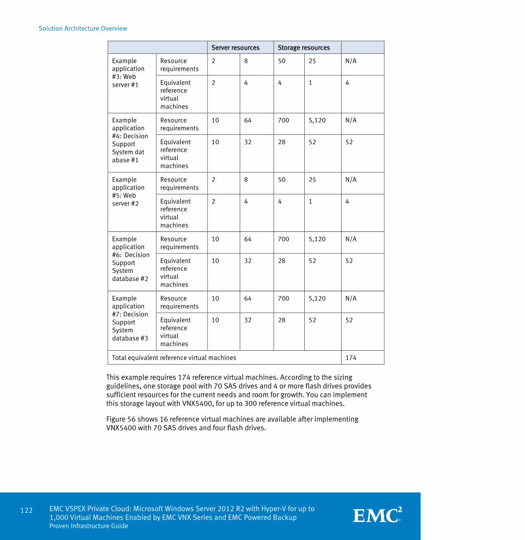
Solution Architecture Overview
122 EMC VSPEX Private Cloud: Microsoft Windows Server 2012 R2 with Hyper-V for up to 1,000 Virtual Machines Enabled by EMC VNX Series and EMC Powered Backup Proven Infrastructure Guide
Server resources Storage resources
Example application #3: Web server #1
Resource requirements
2 8 50 25 N/A
Equivalent reference virtual machines
2 4 4 1 4
Example application #4: Decision Support System dat abase #1
Resource requirements
10 64 700 5,120 N/A
Equivalent reference virtual machines
10 32 28 52 52
Example application #5: Web server #2
Resource requirements
2 8 50 25 N/A
Equivalent reference virtual machines
2 4 4 1 4
Example application #6: Decision Support System database #2
Resource requirements
10 64 700 5,120 N/A
Equivalent reference virtual machines
10 32 28 52 52
Example application #7: Decision Support System database #3
Resource requirements
10 64 700 5,120 N/A
Equivalent reference virtual machines
10 32 28 52 52
Total equivalent reference virtual machines 174
This example requires 174 reference virtual machines. According to the sizing guidelines, one storage pool with 70 SAS drives and 4 or more flash drives provides sufficient resources for the current needs and room for growth. You can implement this storage layout with VNX5400, for up to 300 reference virtual machines.
Figure 56 shows 16 reference virtual machines are available after implementing VNX5400 with 70 SAS drives and four flash drives.

Solution Architecture Overview
EMC VSPEX Private Cloud: Microsoft Windows Server 2012 R2 with Hyper-V for up to 1,000 Virtual Machines Enabled by EMC VNX Series and EMC Powered Backup
Proven Infrastructure Guide
123
Figure 56. Aggregate resource requirements for stage 3
Figure 57 shows the pool configuration in this example.
Figure 57. Pool configuration – stage 3
Usually, the process described in the section Determining equivalent reference virtual machines determines the recommended hardware size for servers and storage. However, in some cases there is a need to further customize the hardware resources available to the system. A complete description of system architecture is beyond the scope of this guide; however, you can perform additional customization at this point.
Storage resources
In some applications, there is a need to separate application data from other workloads. The storage layouts in the VSPEX architectures put all of the virtual machines in a single resource pool. To achieve workload separation, purchase additional disk drives for the application workload and add them to a dedicated pool.
With the method outlined in Determining equivalent reference virtual machines, it is easy to build a virtual infrastructure scaling from 13 reference virtual machines to 1,000 reference virtual machines with the building blocks described in VSPEX storage building blocks, while keeping in mind the recommended limits of each storage array documented in VSPEX private cloud validated maximums.
Server resources
For some workloads the relationship between server needs and storage needs does not match what is outlined in the Reference virtual machine. Size the server and storage layers separately in this scenario.
Fine-tuning hardware resources

Solution Architecture Overview
124 EMC VSPEX Private Cloud: Microsoft Windows Server 2012 R2 with Hyper-V for up to 1,000 Virtual Machines Enabled by EMC VNX Series and EMC Powered Backup Proven Infrastructure Guide
Figure 58. Customizing server resources
To do this, first total the resource requirements for the server components as shown in Table 22. In the Server Component Totals line at the bottom of the worksheet, add up the server resource requirements from the applications in the table.
Note: When customizing resources in this way, confirm that storage sizing is still appropriate. The Storage Component Totals line at the bottom of Table 22 describes the required amount of storage.
Table 22. Server resource component totals
Server resources Storage resources
Application CPU
(virtual CPUs)
Memory (GB)
IOPS Capacity (GB)
Reference virtual machines
Example application #1: Custom built application
Resource requirements
1 3 15 30 N/A
Equivalent reference virtual machines
1 2 1 1 2
Example application #2: Point of Sale system
Resource requirements
4 16 200 200 N/A
Equivalent reference virtual machines
4 8 8 2 8
Example application #3: Web server #1
Resource requirements
2 8 50 25 N/A
Equivalent reference virtual machines
2 4 4 1 4
Example application
Resource requirements
10 64 700 5,120 N/A
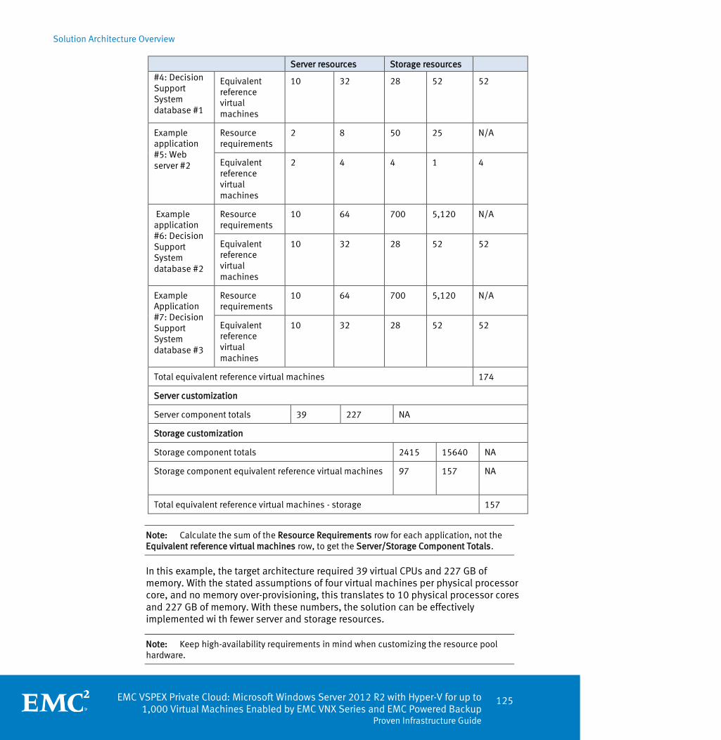
Solution Architecture Overview
EMC VSPEX Private Cloud: Microsoft Windows Server 2012 R2 with Hyper-V for up to 1,000 Virtual Machines Enabled by EMC VNX Series and EMC Powered Backup
Proven Infrastructure Guide
125
Server resources Storage resources #4: Decision Support System database #1
Equivalent reference virtual machines
10 32 28 52 52
Example application #5: Web server #2
Resource requirements
2 8 50 25 N/A
Equivalent reference virtual machines
2 4 4 1 4
Example application #6: Decision Support System database #2
Resource requirements
10 64 700 5,120 N/A
Equivalent reference virtual machines
10 32 28 52 52
Example Application #7: Decision Support System database #3
Resource requirements
10 64 700 5,120 N/A
Equivalent reference virtual machines
10 32 28 52 52
Total equivalent reference virtual machines 174
Server customization
Server component totals 39 227 NA
Storage customization
Storage component totals 2415 15640 NA
Storage component equivalent reference virtual machines
97 157 NA
Total equivalent reference virtual machines - storage 157
Note: Calculate the sum of the Resource Requirements row for each application, not the Equivalent reference virtual machines row, to get the Server/Storage Component Totals.
In this example, the target architecture required 39 virtual CPUs and 227 GB of memory. With the stated assumptions of four virtual machines per physical processor core, and no memory over-provisioning, this translates to 10 physical processor cores and 227 GB of memory. With these numbers, the solution can be effectively implemented wi th fewer server and storage resources.
Note: Keep high-availability requirements in mind when customizing the resource pool hardware.

Solution Architecture Overview
126 EMC VSPEX Private Cloud: Microsoft Windows Server 2012 R2 with Hyper-V for up to 1,000 Virtual Machines Enabled by EMC VNX Series and EMC Powered Backup Proven Infrastructure Guide
Appendix C provides a blank server resource component totals worksheet.
To simplify the sizing of this solution EMC has produced the VSPEX Sizing Tool. This tool uses the same sizing process described in the section above, and also incorporates sizing for other VSPEX solutions.
The VSPEX Sizing Tool enables you to input your resource requirements from the customer’s answers in the qualification worksheet. After you complete the inputs to the VSPEX Sizing Tool, the tool generates a series of recommendations, which allows you to validate your sizing assumptions while providing platform configuration information that meets those requirements. This tool can be accessed at the following location: EMC VSPEX Sizing Tool.
EMC VSPEX Sizing Tool

EMC VSPEX Private Cloud: Microsoft Windows Server 2012 R2 with Hyper-V for up to 1,000 Virtual Machines Enabled by EMC VNX Series and EMC Powered Backup
Proven Infrastructure Guide
127
Chapter 5 VSPEX Configuration Guidelines
This chapter presents the following topics:
Overview ................................................................................................................ 128
Pre-deployment tasks ............................................................................................ 129
Customer configuration data .................................................................................. 130
Prepare switches, connect network, and configure switches ................................. 131
Prepare and configure storage array ...................................................................... 134
Install and configure Hyper-V hosts ....................................................................... 151
Install and configure SQL Server database ............................................................. 153
System Center Virtual Machine Manager server deployment ................................. 154
Summary ................................................................................................................ 157

VSPEX Configuration Guidelines
128 EMC VSPEX Private Cloud: Microsoft Windows Server 2012 R2 with Hyper-V for up to 1,000 Virtual Machines Enabled by EMC VNX Series and EMC Powered Backup Proven Infrastructure Guide
Overview
The deployment process consists of the main stages listed in Table 23. After deployment, integrate the VSPEX infrastructure with the existing customer network and server infrastructure. The table also includes references to chapters that contain relevant procedures.
Table 23. Deployment process overview
Stage Description Reference
1 Verify prerequisites Pre-deployment tasks
2 Obtain the deployment tools Deployment prerequisites
3 Gather customer configuration data
Customer configuration data
4 Rack and cable the components
Refer to the vendor documentation.
5 Configure the switches and networks, connect to the customer network
Prepare switches, connect network, and configure switches
6 Install and configure the VNX Prepare and configure storage array
7 Configure virtual machine storage
Prepare and configure storage array
8 Install and configure the servers
Install and configure Hyper-V hosts
9 Set up SQL Server (used by SCVMM)
Install and configure SQL Server database
10 Install and configure SCVMM System Center Virtual Machine Manager
server deployment

VSPEX Configuration Guidelines
EMC VSPEX Private Cloud: Microsoft Windows Server 2012 R2 with Hyper-V for up to 1,000 Virtual Machines Enabled by EMC VNX Series and EMC Powered Backup
Proven Infrastructure Guide
129
Pre-deployment tasks
The pre-deployment tasks shown in Table 24 include procedures not directly related to environment installation and configuration, but provide needed results at the time of installation. Examples of pre-deployment tasks are collecting hostnames, IP addresses, VLAN IDs, license keys, and installation media. Perform these tasks before the customer visit to decrease the time required onsite.
Table 24. Tasks for pre-deployment
Task Description Reference
Gather documents
Gather the related documents listed in Appendix D. These documents provide detail on setup procedures and deployment best practices for the various components of the solution.
References: EMC documentation
Gather tools
Gather the required and optional tools for the deployment. Use Table 25 to confirm that all equipment, software, and appropriate licenses are available before starting the deployment process.
Table 25: Deployment prerequisites checklist
Gather data
Collect the customer-specific configuration data for networking, naming, and required accounts. Enter this information into the Customer configuration data sheet for reference during the deployment process.
Appendix B
Table 25 lists the hardware, software, and licenses required to configure the solution. For additional information, refer to Table 9.
Table 25. Deployment prerequisites checklist
Requirement Description Reference
Hardware Sufficient physical server capacity to host 200, 300, 600, or 1,000 virtual servers
Table 8
Windows Server 2012 servers to host virtual infrastructure servers
Note: The existing infrastructure may already meet this requirement.
Switch port capacity and capabilities as required by the virtual server infrastructure
EMC VNX5200 (200 virtual machines), VNX5400 (300 virtual machines), VNX5600 (600 virtual machines) or VNX5800 (1,000 virtual machines): Multiprotocol storage array with the
Overview
Deployment prerequisites

VSPEX Configuration Guidelines
130 EMC VSPEX Private Cloud: Microsoft Windows Server 2012 R2 with Hyper-V for up to 1,000 Virtual Machines Enabled by EMC VNX Series and EMC Powered Backup Proven Infrastructure Guide
Requirement Description Reference
required disk layout
Software SCVMM 2012 SP1 installation media
Microsoft Windows Server 2012 installation media
Microsoft Windows Server 2012 installation media (optional for virtual machine guest OS)
Microsoft SQL Server 2012 or newer installation media
Note: The existing infrastructure may already meet this requirement.
Licenses Microsoft Windows Server 2012 Standard (or higher) license keys (optional)
Microsoft Windows Server 2012 R2 Datacenter Edition license keys
Note: An existing Microsoft Key Management Server (KMS) may already meet this requirement.
Microsoft SQL Server license key
Note: The existing infrastructure may already meet this requirement.
SCVMM 2012 SP1 license keys
Customer configuration data
Assemble information such as IP addresses and hostnames during the planning process to reduce the onsite time.
Appendix B provides a table to maintain a record of relevant customer information. Add, record, or modify information as needed during the deployment process.
Additionally, complete the VNX File and Unified Worksheet, available on EMC Online Support, to record the most comprehensive array-specific information.
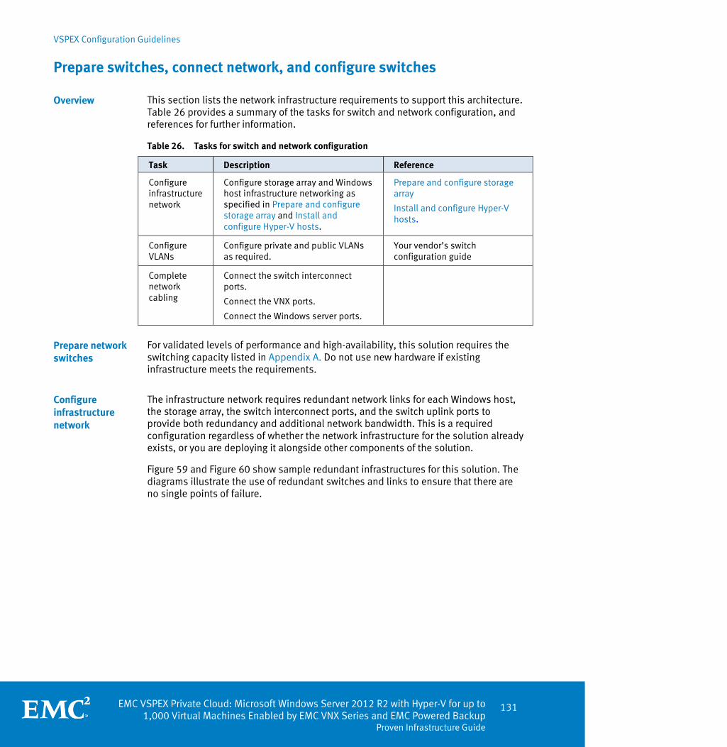
VSPEX Configuration Guidelines
EMC VSPEX Private Cloud: Microsoft Windows Server 2012 R2 with Hyper-V for up to 1,000 Virtual Machines Enabled by EMC VNX Series and EMC Powered Backup
Proven Infrastructure Guide
131
Prepare switches, connect network, and configure switches
This section lists the network infrastructure requirements to support this architecture. Table 26 provides a summary of the tasks for switch and network configuration, and references for further information.
Table 26. Tasks for switch and network configuration
Task Description Reference
Configure infrastructure network
Configure storage array and Windows host infrastructure networking as specified in Prepare and configure storage array and Install and configure Hyper-V hosts.
Prepare and configure storage array
Install and configure Hyper-V hosts.
Configure VLANs
Configure private and public VLANs as required.
Your vendor’s switch configuration guide
Complete network cabling
Connect the switch interconnect ports.
Connect the VNX ports.
Connect the Windows server ports.
For validated levels of performance and high-availability, this solution requires the switching capacity listed in Appendix A. Do not use new hardware if existing infrastructure meets the requirements.
The infrastructure network requires redundant network links for each Windows host, the storage array, the switch interconnect ports, and the switch uplink ports to provide both redundancy and additional network bandwidth. This is a required configuration regardless of whether the network infrastructure for the solution already exists, or you are deploying it alongside other components of the solution.
Figure 59 and Figure 60 show sample redundant infrastructures for this solution. The diagrams illustrate the use of redundant switches and links to ensure that there are no single points of failure.
Overview
Prepare network switches
Configure infrastructure network

VSPEX Configuration Guidelines
132 EMC VSPEX Private Cloud: Microsoft Windows Server 2012 R2 with Hyper-V for up to 1,000 Virtual Machines Enabled by EMC VNX Series and EMC Powered Backup Proven Infrastructure Guide
In Figure 59 converged switches provide customers different protocol options (FC, FCoE or iSCSI) for the storage network. While existing FC switches are acceptable for FC or FCoE, use 10 Gb Ethernet network switches for iSCSI.
Figure 59. Sample Ethernet network architecture - block variant

VSPEX Configuration Guidelines
EMC VSPEX Private Cloud: Microsoft Windows Server 2012 R2 with Hyper-V for up to 1,000 Virtual Machines Enabled by EMC VNX Series and EMC Powered Backup
Proven Infrastructure Guide
133
Figure 60 shows a sample redundant Ethernet infrastructure for file storage, and illustrates the use of redundant switches and links to ensure that no single points of failure exist in the network connectivity.
Figure 60. Sample Ethernet network architecture - file variant
Ensure that there are adequate switch ports for the storage array and Windows hosts. Use a minimum three VLANs for the following purposes:
Virtual machine networking and traffic management (These are customer-facing networks. Separate them if required)
Live Migration networking (Private network)
Storage networking (iSCSI or SMB, private network)
Use jumbo frames for iSCSI and SMB protocols. Set the MTU to 9,000 on the switch ports for the iSCSI or SMB storage network. Consult your switch configuration guide for instructions.
Configure VLANs
Configure jumbo frames (iSCSI or SMB only)

VSPEX Configuration Guidelines
134 EMC VSPEX Private Cloud: Microsoft Windows Server 2012 R2 with Hyper-V for up to 1,000 Virtual Machines Enabled by EMC VNX Series and EMC Powered Backup Proven Infrastructure Guide
Ensure the following:
All servers, storage arrays, switch interconnects, and switch uplinks plug into separate switching infrastructures and have redundant connections.
There is a complete connection to the existing customer network.
Note: Ensure that unforeseen interactions do not cause service interruptions when you connect the new equipment to the existing customer network.
Prepare and configure storage array
Implementation instructions and best practices may vary because of the storage network protocol selected for the solution. Each case contains the following steps:
1. Configure the VNX.
2. Provision storage to the hosts.
3. Configure FAST VP.
4. Optionally configure FAST Cache.
The sections below cover the options for each step separately depending on whether one of the block protocols (FC, FCoE, iSCSI), or the file protocol (CIFS) is selected
For FC, FCoE, or iSCSI, refer to VNX configuration for block protocols.
For CIFS, refer to VNX configuration for file protocols.
This section describes how to configure the VNX storage array for host access using block protocols such as FC, FCoE, or iSCSI. In this solution, the VNX provides data storage for Windows hosts.
Table 27. Tasks for VNX configuration for block protocols
Task Description Reference
Prepare the VNX Physically install the VNX hardware using the procedures in the product documentation.
EMC VNX5200 Unified Installation Guide
EMC VNX5400 Unified Installation Guide
EMC VNX5600 Unified Installation Guide
EMC VNX5800 Unified Installation Guide
Unisphere System Getting Started Guide
Your vendor’s switch configuration guide
Set up the initial VNX configuration
Configure the IP addresses and other key parameters on the VNX.
Provision storage for Hyper-V hosts
Create the storage areas required for the solution.
Complete network cabling
VNX configuration for block protocols

VSPEX Configuration Guidelines
EMC VSPEX Private Cloud: Microsoft Windows Server 2012 R2 with Hyper-V for up to 1,000 Virtual Machines Enabled by EMC VNX Series and EMC Powered Backup
Proven Infrastructure Guide
135
Prepare the VNX
The installation guides for VNX5200, VNX5400, VNX5600, and VNX5800 provide instructions to assemble, rack, cable, and power up the VNX. There are no specific setup steps for this solution.
Set up the initial VNX configuration
After the initial VNX setup, configure key information about the existing environment to enable the storage array to communicate with the other devices in the environment. Configure the following common items in accordance with your IT data center policies and existing infrastructure information:
DNS
NTP
Storage network interfaces
For data connections using FC or FCoE Connect one or more servers to the VNX storage system, either directly or through qualified FC or FCoE switches. Refer to the EMC Host Connectivity Guide for Windows for more detailed instructions.
For data connections using iSCSI Connect one or more servers to the VNX storage system, either directly or through qualified IP switches. Refer to the EMC Host Connectivity Guide for Windows for more detailed instructions.
Additionally, configure the following items in accordance with your IT data center policies and existing infrastructure information:
1. Set up a storage network IP address:
Logically isolate the storage network from the other networks in the solution, as described in Chapter 3. This ensures that other network traffic does not impact traffic between the hosts and the storage.
2. Enable jumbo frames on the VNX iSCSI ports:
Use jumbo frames for iSCSI networks to permit greater network bandwidth. Apply the MTU size specified below across all the network interfaces in the environment:
a. In Unisphere, select Settings > Network > Settings for Block.
b. Select the appropriate iSCSI network interface.
c. Click Properties.
d. Set the MTU size to 9,000.
e. Click OK to apply the changes.
The reference documents listed in Table 27 provide more information on how to configure the VNX platform. Storage configuration guidelines provide more information on the disk layout.

VSPEX Configuration Guidelines
136 EMC VSPEX Private Cloud: Microsoft Windows Server 2012 R2 with Hyper-V for up to 1,000 Virtual Machines Enabled by EMC VNX Series and EMC Powered Backup Proven Infrastructure Guide
Provision storage for Hyper-V hosts
This section describes provisioning block storage for Hyper-V hosts. To provision file storage, refer to VNX configuration for file protocols.
Complete the following steps in Unisphere to configure LUNs on the VNX array to store virtual servers:
1. Create the number of storage pools required for the environment based on
the sizing information in Chapter 4. This example uses the array recommended maximums described in Chapter 4.
a. Log in to Unisphere.
b. Select the array for this solution.
c. Select Storage > Storage Configuration > Storage Pools.
d. Click Pools.
e. Click Create.
Note: The pool does not use system drives for additional storage.
Table 28. Storage allocation table for block
Configuration Number of pools
Number of 15K SAS drives per pool
Number of flash drives per pool
Number of LUNs per pool
LUN size (TB)
200 virtual machines
1 45 2 2 7
1 30 2 2 4
Total 2 75 4 4 2 x 7 TB LUNs 2 x 4 TB LUNs
300 virtual machines
2 45 2 2 7
1 20 2 2 3
Total 3 110 6 6 4 x 7 TB LUNs 2 x 3 TB LUNs
600 virtual machines
4 45 2 2 7
1 40 2 2 6
Total 5 220 10 10 8 x 7 TB LUNs 2 x 6 TB LUNs
1000 virtual machines
8 45 2 2 7
Total 8 360 16 16 16 x 7 TB LUNs
Note: Each virtual machine occupies 102 GB in this solution, with 100 GB for the OS and user space, and a 2 GB swap file.
2. Create the hot spare disks at this point. Refer to the appropriate VNX
installation guide for additional information.
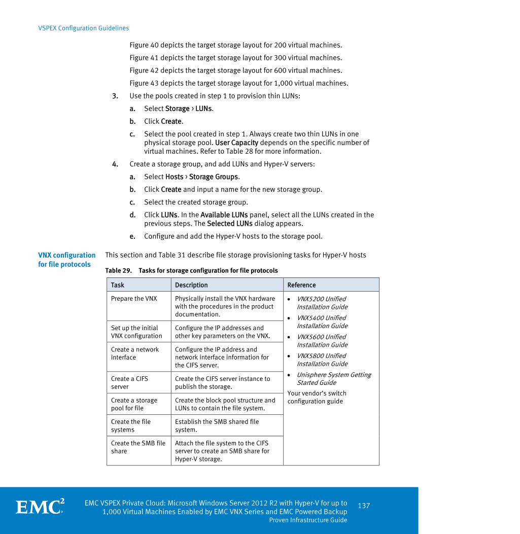
VSPEX Configuration Guidelines
EMC VSPEX Private Cloud: Microsoft Windows Server 2012 R2 with Hyper-V for up to 1,000 Virtual Machines Enabled by EMC VNX Series and EMC Powered Backup
Proven Infrastructure Guide
137
Figure 40 depicts the target storage layout for 200 virtual machines.
Figure 41 depicts the target storage layout for 300 virtual machines.
Figure 42 depicts the target storage layout for 600 virtual machines.
Figure 43 depicts the target storage layout for 1,000 virtual machines.
3. Use the pools created in step 1 to provision thin LUNs:
a. Select Storage > LUNs.
b. Click Create.
c. Select the pool created in step 1. Always create two thin LUNs in one physical storage pool. User Capacity depends on the specific number of virtual machines. Refer to Table 28 for more information.
4. Create a storage group, and add LUNs and Hyper-V servers:
a. Select Hosts > Storage Groups.
b. Click Create and input a name for the new storage group.
c. Select the created storage group.
d. Click LUNs. In the Available LUNs panel, select all the LUNs created in the previous steps. The Selected LUNs dialog appears.
e. Configure and add the Hyper-V hosts to the storage pool.
This section and Table 31 describe file storage provisioning tasks for Hyper-V hosts
Table 29. Tasks for storage configuration for file protocols
Task Description Reference
Prepare the VNX Physically install the VNX hardware with the procedures in the product documentation.
VNX5200 Unified Installation Guide
VNX5400 Unified Installation Guide
VNX5600 Unified Installation Guide
VNX5800 Unified Installation Guide
Unisphere System Getting Started Guide
Your vendor’s switch configuration guide
Set up the initial VNX configuration
Configure the IP addresses and other key parameters on the VNX.
Create a network interface
Configure the IP address and network interface information for the CIFS server.
Create a CIFS server
Create the CIFS server instance to publish the storage.
Create a storage pool for file
Create the block pool structure and LUNs to contain the file system.
Create the file systems
Establish the SMB shared file system.
Create the SMB file share
Attach the file system to the CIFS server to create an SMB share for Hyper-V storage.
VNX configuration for file protocols

VSPEX Configuration Guidelines
138 EMC VSPEX Private Cloud: Microsoft Windows Server 2012 R2 with Hyper-V for up to 1,000 Virtual Machines Enabled by EMC VNX Series and EMC Powered Backup Proven Infrastructure Guide
Prepare the VNX
The installation guides for VNX5200, VNX5400, VNX5600, and VNX5800 provide instructions to assemble, rack, cable, and power up the VNX. There are no specific setup steps for this solution.
Set up the initial VNX configuration
After the initial VNX setup, configure key information about the existing environment to allow the storage array to communicate with the other devices in the environment. Ensure one or more servers connect to the VNX storage system, either directly or through qualified IP switches. Configure the following common items in accordance with your IT data center policies and existing infrastructure information:
DNS
NTP
Storage network interfaces
Storage network IP address
CIFS services and Active Directory Domain membership
Refer to the EMC Host Connectivity Guide for Windows for more detailed instructions.
Enable jumbo frames on the VNX storage network interfaces Use Jumbo frames for storage networks to permit greater network bandwidth. Apply the MTU size specified below across all the network interfaces in the environment.
Complete the following steps to enable jumbo frames: 1. In Unisphere, select Settings > Network > Settings for File.
2. Select the appropriate network interface from the Interfaces tab.
3. Click Properties.
4. Set the MTU size to 9,000.
5. Click OK to apply the changes.
The reference documents listed in Table 27 provide more information on how to configure the VNX platform. The Storage configuration guidelines section provide more information on the disk layout.
Create a network interface
A network interface maps to a CIFS server. CIFS servers provide access to file shares over the network
Complete the following steps to create a network interface: 1. Log in to the VNX.
2. In Unisphere, select Settings > Network > Settings For File.
3. On the Interfaces tab, click Create as shown in Figure 61.

VSPEX Configuration Guidelines
EMC VSPEX Private Cloud: Microsoft Windows Server 2012 R2 with Hyper-V for up to 1,000 Virtual Machines Enabled by EMC VNX Series and EMC Powered Backup
Proven Infrastructure Guide
139
Figure 61. Network Settings for File dialog box
In the Create Network Interface wizard, complete the following steps: 1. Select the Data Mover which will provide access to the file share.
2. Select the device name where the network interface will reside.
Note: Run the following command as nasadmin on the Control Station to ensure that the selected device has a link connected: > server_sysconfig <datamovername> -pci This command lists the link status (UP or DOWN) for all devices on the specified Data Mover.
3. Type an IP address for the interface.
4. Type a Name for the interface.
5. Type the netmask for the interface.
The Broadcast Address appears automatically after you provide the IP address and netmask.
6. Set the MTU size for the interface to 9,000.
Note: Ensure that all devices on the network (switches, servers, and so on) have the same MTU size.
7. If required, specify the VLAN ID.
8. Click OK, as shown in Figure 62.
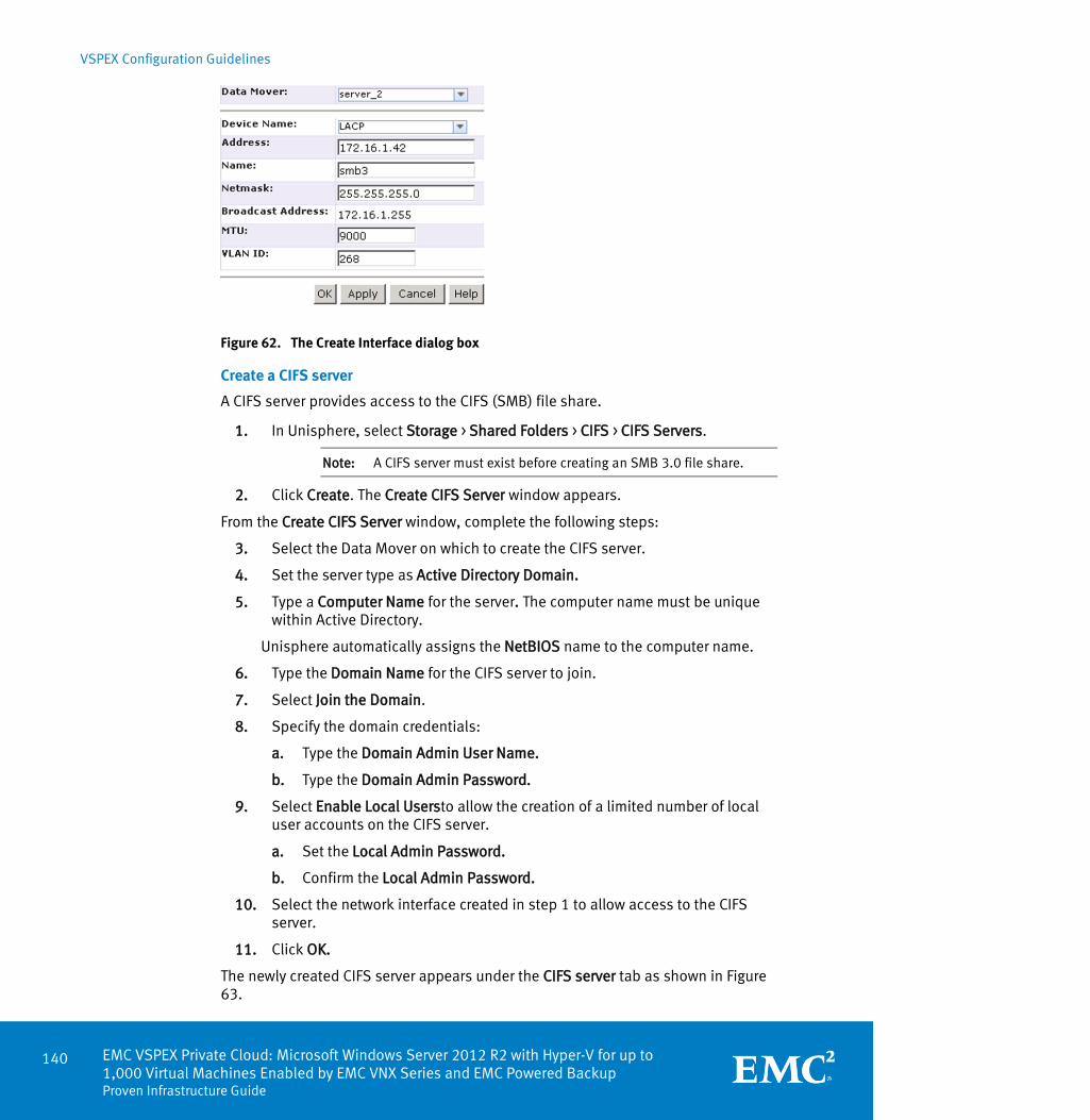
VSPEX Configuration Guidelines
140 EMC VSPEX Private Cloud: Microsoft Windows Server 2012 R2 with Hyper-V for up to 1,000 Virtual Machines Enabled by EMC VNX Series and EMC Powered Backup Proven Infrastructure Guide
Figure 62. The Create Interface dialog box
Create a CIFS server
A CIFS server provides access to the CIFS (SMB) file share. 1. In Unisphere, select Storage > Shared Folders > CIFS > CIFS Servers.
Note: A CIFS server must exist before creating an SMB 3.0 file share.
2. Click Create. The Create CIFS Server window appears.
From the Create CIFS Server window, complete the following steps:
3. Select the Data Mover on which to create the CIFS server.
4. Set the server type as Active Directory Domain.
5. Type a Computer Name for the server. The computer name must be unique within Active Directory.
Unisphere automatically assigns the NetBIOS name to the computer name.
6. Type the Domain Name for the CIFS server to join.
7. Select Join the Domain.
8. Specify the domain credentials:
a. Type the Domain Admin User Name.
b. Type the Domain Admin Password.
9. Select Enable Local Usersto allow the creation of a limited number of local user accounts on the CIFS server.
a. Set the Local Admin Password.
b. Confirm the Local Admin Password.
10. Select the network interface created in step 1 to allow access to the CIFS server.
11. Click OK.
The newly created CIFS server appears under the CIFS server tab as shown in Figure 63.
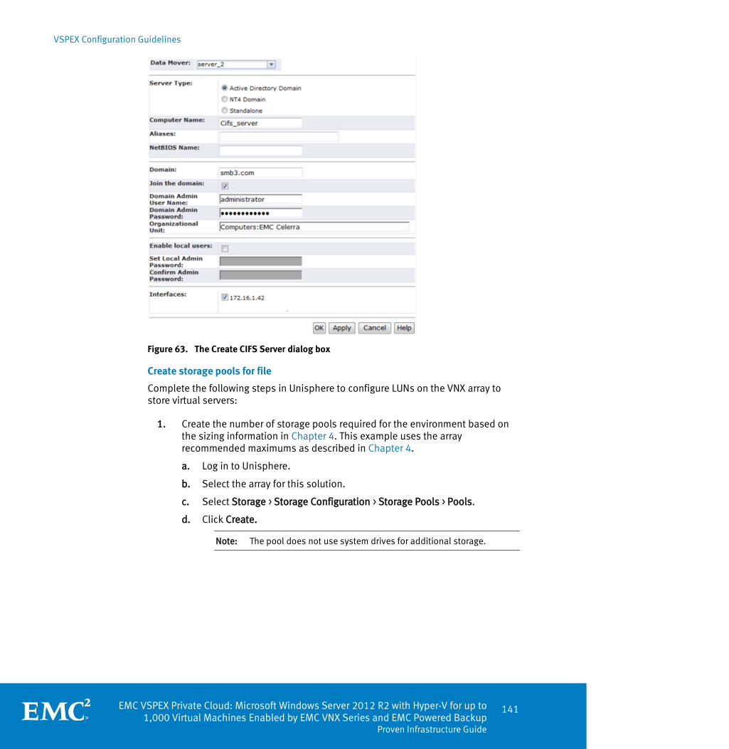
VSPEX Configuration Guidelines
EMC VSPEX Private Cloud: Microsoft Windows Server 2012 R2 with Hyper-V for up to 1,000 Virtual Machines Enabled by EMC VNX Series and EMC Powered Backup
Proven Infrastructure Guide
141
Figure 63. The Create CIFS Server dialog box
Create storage pools for file
Complete the following steps in Unisphere to configure LUNs on the VNX array to store virtual servers:
1. Create the number of storage pools required for the environment based on
the sizing information in Chapter 4. This example uses the array recommended maximums as described in Chapter 4.
a. Log in to Unisphere.
b. Select the array for this solution.
c. Select Storage > Storage Configuration > Storage Pools > Pools.
d. Click Create.
Note: The pool does not use system drives for additional storage.

VSPEX Configuration Guidelines
142 EMC VSPEX Private Cloud: Microsoft Windows Server 2012 R2 with Hyper-V for up to 1,000 Virtual Machines Enabled by EMC VNX Series and EMC Powered Backup Proven Infrastructure Guide
Table 30. Storage allocation table for file
Configuration Number of pools
Number of 15K SAS drives per pool
Number of Flash drives per pool
Number of LUNs per pool
Number of FS per storage pool for file
LUN size (GB)
FS size (TB)
200 virtual machines
1 45 2 20 2 800 5
1 30 2 20 2 600 4
Total 2 75 4 40 4 20 X 800GB LUNs 20 X 600GB LUNs
2 x 5 TB FS 2 x 4 TB FS
300 virtual machines
2 45 2 20 2 800 7
1 20 2 20 2 400 3
Total 3 110 6 60 6 40 X 800GB LUNs 20 X 400GB LUNs
4 x 7 TB FS 2 x 3 TB FS
600 virtual machines
4 45 2 20 2 800 7
1 40 2 20 2 700 6
Total 5 220 10 100 10 80 X 800GB LUNs 20 X 700GB LUNs
8 x 7 TB FS 2 x 6 TB FS
1000 virtual machines
8 45 2 20 2 800 7
Total 8 360 16 160 16 160 X 800GB LUNs
16 x 7 TB FS
2. Create the hot spare disks at this point. Refer to the appropriate VNX
installation guide for additional information.
Figure 40 depicts the target storage layout for 200 virtual machines.
Figure 41 depicts the target storage layout for 300 virtual machines.
Figure 42 depicts the target storage layout for 600 virtual machines.
Figure 43 depicts the target storage layout for 1,000 virtual machines.
3. Provision LUNs on the pool created in step 1:
a. Select Storage > LUNs.
b. Click Create.
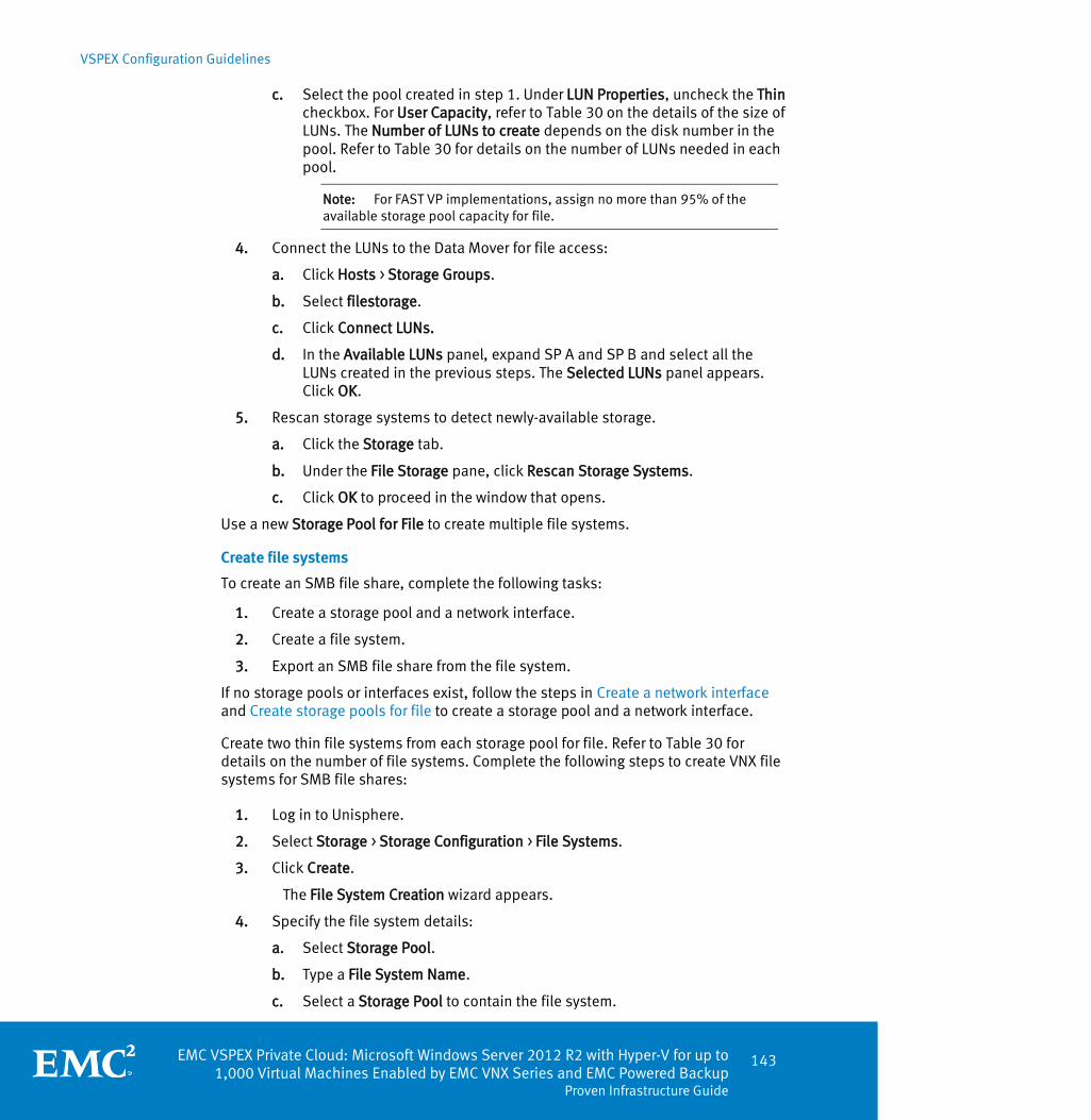
VSPEX Configuration Guidelines
EMC VSPEX Private Cloud: Microsoft Windows Server 2012 R2 with Hyper-V for up to 1,000 Virtual Machines Enabled by EMC VNX Series and EMC Powered Backup
Proven Infrastructure Guide
143
c. Select the pool created in step 1. Under LUN Properties, uncheck the Thin checkbox. For User Capacity, refer to Table 30 on the details of the size of LUNs. The Number of LUNs to create depends on the disk number in the pool. Refer to Table 30 for details on the number of LUNs needed in each pool.
Note: For FAST VP implementations, assign no more than 95% of the available storage pool capacity for file.
4. Connect the LUNs to the Data Mover for file access:
a. Click Hosts > Storage Groups.
b. Select filestorage.
c. Click Connect LUNs.
d. In the Available LUNs panel, expand SP A and SP B and select all the LUNs created in the previous steps. The Selected LUNs panel appears. Click OK.
5. Rescan storage systems to detect newly-available storage.
a. Click the Storage tab.
b. Under the File Storage pane, click Rescan Storage Systems.
c. Click OK to proceed in the window that opens.
Use a new Storage Pool for File to create multiple file systems.
Create file systems
To create an SMB file share, complete the following tasks: 1. Create a storage pool and a network interface.
2. Create a file system.
3. Export an SMB file share from the file system.
If no storage pools or interfaces exist, follow the steps in Create a network interface and Create storage pools for file to create a storage pool and a network interface.
Create two thin file systems from each storage pool for file. Refer to Table 30 for details on the number of file systems. Complete the following steps to create VNX file systems for SMB file shares:
1. Log in to Unisphere.
2. Select Storage > Storage Configuration > File Systems.
3. Click Create.
The File System Creation wizard appears.
4. Specify the file system details:
a. Select Storage Pool.
b. Type a File System Name.
c. Select a Storage Pool to contain the file system.
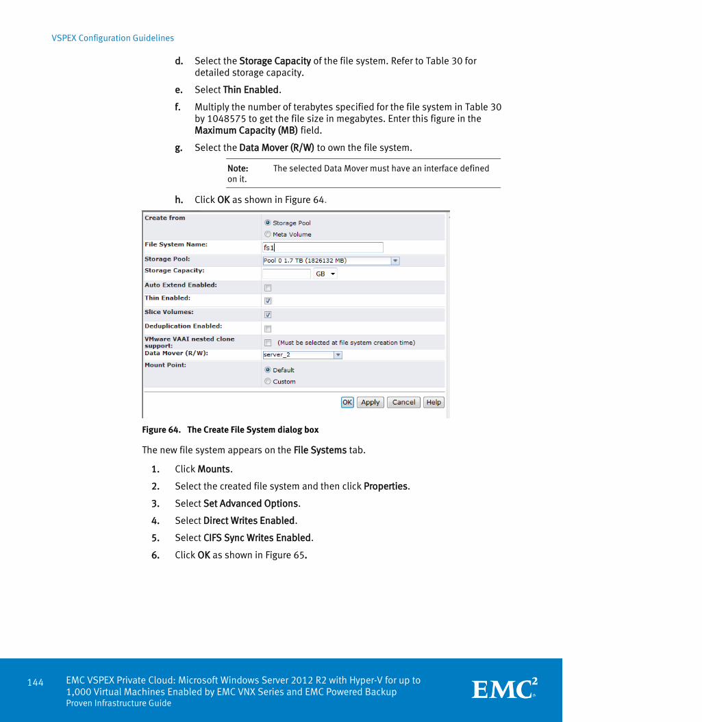
VSPEX Configuration Guidelines
144 EMC VSPEX Private Cloud: Microsoft Windows Server 2012 R2 with Hyper-V for up to 1,000 Virtual Machines Enabled by EMC VNX Series and EMC Powered Backup Proven Infrastructure Guide
d. Select the Storage Capacity of the file system. Refer to Table 30 for detailed storage capacity.
e. Select Thin Enabled.
f. Multiply the number of terabytes specified for the file system in Table 30 by 1048575 to get the file size in megabytes. Enter this figure in the Maximum Capacity (MB) field.
g. Select the Data Mover (R/W) to own the file system.
Note: The selected Data Mover must have an interface defined on it.
h. Click OK as shown in Figure 64.
Figure 64. The Create File System dialog box
The new file system appears on the File Systems tab. 1. Click Mounts.
2. Select the created file system and then click Properties.
3. Select Set Advanced Options.
4. Select Direct Writes Enabled.
5. Select CIFS Sync Writes Enabled.
6. Click OK as shown in Figure 65.

VSPEX Configuration Guidelines
EMC VSPEX Private Cloud: Microsoft Windows Server 2012 R2 with Hyper-V for up to 1,000 Virtual Machines Enabled by EMC VNX Series and EMC Powered Backup
Proven Infrastructure Guide
145
Figure 65. The File System Properties dialog box
Create the SMB file share
After completing creating the file system, the SMB file share can be created.
To create the share, complete the following steps: 1. From the VNX dashboard, hover over the Storage tab.
2. Select Shared folders > CIFS.
3. From the shares page click Create. The Create CIFS Share window opens.
4. Select the Data Mover on which to create the share (the same Data Mover that owns the CIFS server).
5. Specify a name for the share.
6. Specify the file system for the share. Leave the default path as is.
7. Select the CIFS server to provide access to the share as shown in Figure 66.
8. Optionally specify a user limit, or any comments about the share.
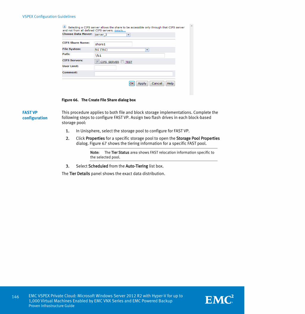
VSPEX Configuration Guidelines
146 EMC VSPEX Private Cloud: Microsoft Windows Server 2012 R2 with Hyper-V for up to 1,000 Virtual Machines Enabled by EMC VNX Series and EMC Powered Backup Proven Infrastructure Guide
Figure 66. The Create File Share dialog box
This procedure applies to both file and block storage implementations. Complete the following steps to configure FAST VP. Assign two flash drives in each block-based storage pool:
1. In Unisphere, select the storage pool to configure for FAST VP.
2. Click Properties for a specific storage pool to open the Storage Pool Properties dialog. Figure 67 shows the tiering information for a specific FAST pool.
Note: The Tier Status area shows FAST relocation information specific to the selected pool.
3. Select Scheduled from the Auto-Tiering list box.
The Tier Details panel shows the exact data distribution.
FAST VP configuration
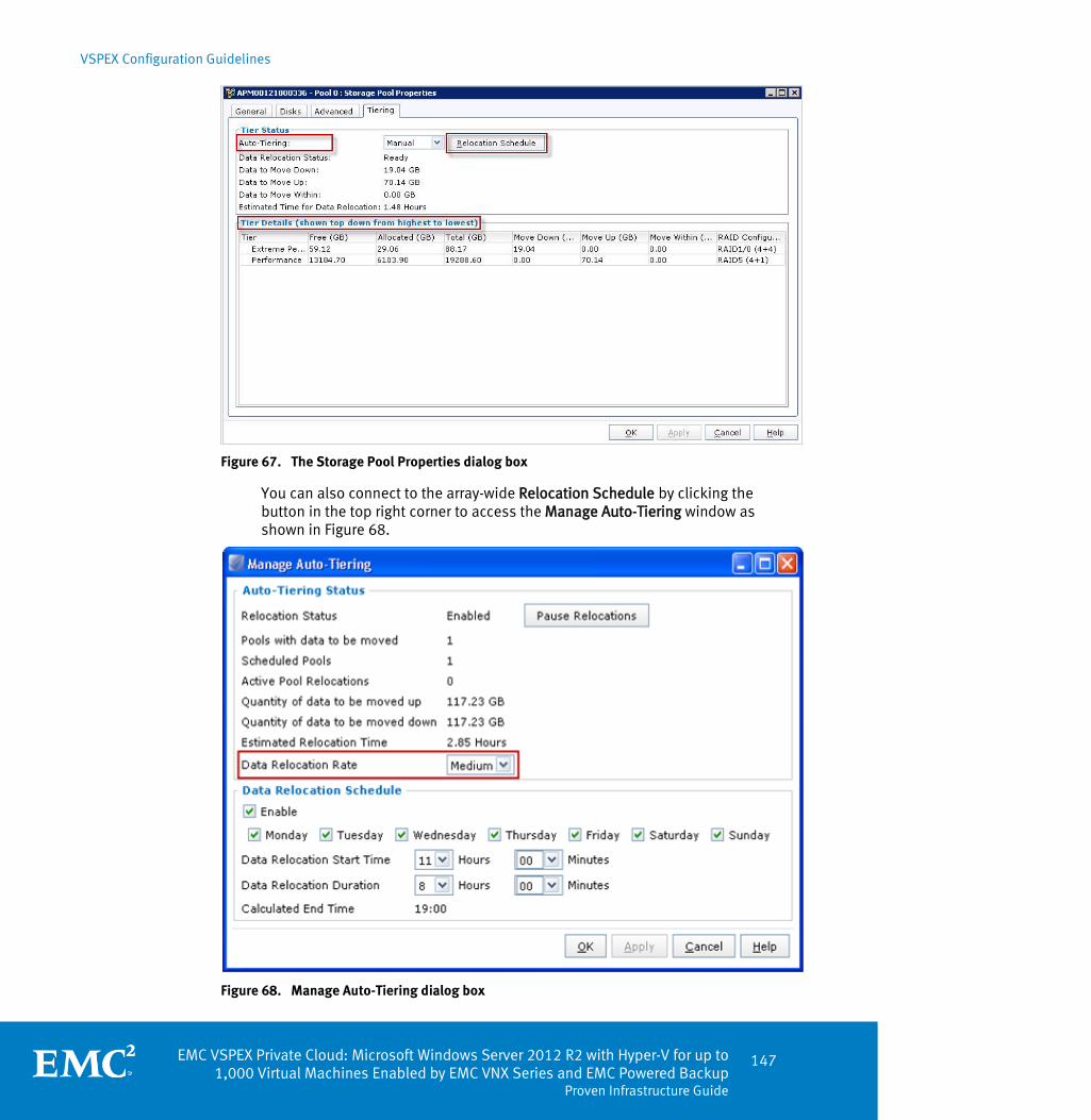
VSPEX Configuration Guidelines
EMC VSPEX Private Cloud: Microsoft Windows Server 2012 R2 with Hyper-V for up to 1,000 Virtual Machines Enabled by EMC VNX Series and EMC Powered Backup
Proven Infrastructure Guide
147
Figure 67. The Storage Pool Properties dialog box
You can also connect to the array-wide Relocation Schedule by clicking the button in the top right corner to access the Manage Auto-Tiering window as shown in Figure 68.
Figure 68. Manage Auto-Tiering dialog box

VSPEX Configuration Guidelines
148 EMC VSPEX Private Cloud: Microsoft Windows Server 2012 R2 with Hyper-V for up to 1,000 Virtual Machines Enabled by EMC VNX Series and EMC Powered Backup Proven Infrastructure Guide
From this status dialog, users can control the Data Relocation Rate. The default rate is Medium to minimize the impact on host I/O.
Note: FAST is a completely automated tool that provides the ability to create a relocation schedule. Schedule the relocations during off-hours to minimize any potential performance impact.
You can configure FAST Cache as an option.
Note: Use the flash drives listed in Sizing guidelines for FAST VP configurations as described in FAST VP configuration. FAST Cache is an optional component of this solution that provides improved performance as outlined in Chapter 3.
To configure FAST Cache on the storage pools for this solution, complete the following steps:
1. Configure flash drives as FAST Cache:
a. Click Properties from the Unisphere dashboard or Manage Cache in the left-hand pane of the Unisphere interface to access the Storage System Properties window as shown in Figure 69.
b. Click the FAST Cache tab to view FAST Cache information.
Figure 69. The Storage System Properties dialog box
FAST Cache configuration

VSPEX Configuration Guidelines
EMC VSPEX Private Cloud: Microsoft Windows Server 2012 R2 with Hyper-V for up to 1,000 Virtual Machines Enabled by EMC VNX Series and EMC Powered Backup
Proven Infrastructure Guide
149
c. Click Create to open the Create FAST Cache window as shown in Figure 70.
The RAID Type field displays RAID 1 when the FAST Cache is created. This window also provides the option to select the drives for the FAST Cache. The bottom of the screen shows the flash drives used to create the FAST Cache. Select Manual to choose the drives manually.
d. Refer to Storage configuration guidelines to determine the number of flash drives required in this solution.
Note: If a sufficient number of flash drives are not available, VNX displays an error message and does not create the FAST Cache.
Figure 70. The Create FAST Cache dialog box
2. Enable FAST Cache in the storage pool.
If a LUN is created in a storage pool, you can only configure FAST Cache for that LUN at the storage pool level. All the LUNs created in the storage pool have FAST Cache enabled or disabled. Configure the LUNS from the advanced tab on the Create Storage Pool window shown in Figure 71. After installation, FAST Cache is enabled by default at storage pool creation.

VSPEX Configuration Guidelines
150 EMC VSPEX Private Cloud: Microsoft Windows Server 2012 R2 with Hyper-V for up to 1,000 Virtual Machines Enabled by EMC VNX Series and EMC Powered Backup Proven Infrastructure Guide
Figure 71. Advanced tab in the Create Storage Pool dialog
If the storage pool already exists, use the Advanced tab of the Storage Pool Properties window to configure FAST Cache as shown in Figure 72.
Figure 72. Advanced tab in the Storage Pool Properties dialog
Note: The VNX FAST Cache feature on does not cause an instant performance improvement. The system must collect data about access patterns, and promote frequently used information into the cache. This process can take several hours. Array performance gradually improves during this time.

VSPEX Configuration Guidelines
EMC VSPEX Private Cloud: Microsoft Windows Server 2012 R2 with Hyper-V for up to 1,000 Virtual Machines Enabled by EMC VNX Series and EMC Powered Backup
Proven Infrastructure Guide
151
Install and configure Hyper-V hosts
This section provides the requirements for the installation and configuration of the Windows hosts and infrastructure servers to support the architecture.
Table 31 describes the required tasks.
Table 31. Tasks for server installation
Task Description Reference
Install Windows hosts
Install Windows Server 2012 on the physical servers for the solution.
http://technet.microsoft.com/
Install Hyper-V and configure Failover Clustering
1. Add the Hyper-V Server role.
2. Add the Failover Clustering feature.
3. Create and configure the Hyper-V cluster.
http://technet.microsoft.com/
Configure windows hosts networking
Configure Windows hosts networking, including NIC teaming and the Virtual Switch network.
http://technet.microsoft.com/
Install PowerPath on Windows Servers
Install and configure PowerPath to manage multipathing for VNX LUNs
PowerPath and PowerPath/VE for Windows Installation and Administration Guide.
Plan virtual machine memory allocations
Ensure that Windows Hyper-V guest memory management features are configured properly for the environment.
http://technet.microsoft.com/
Follow Microsoft best practices to install Windows Server 2012 and the Hyper-V role on the physical servers for this solution.
To install and configure Failover Clustering, complete the following steps: 1. Install and patch Windows Server 2012 on each Windows host.
2. Configure the Hyper-V role, and the Failover Clustering feature.
3. Install the HBA drivers, or configure iSCSI initiators on each Windows host. For details, refer to EMC Host Connectivity Guide for Windows.
Table 31 provides the steps and references to accomplish the configuration tasks.
Overview
Install Windows hosts
Install Hyper-V and configure failover clustering
VSPEX Configuration Guidelines
152 EMC VSPEX Private Cloud: Microsoft Windows Server 2012 R2 with Hyper-V for up to 1,000 Virtual Machines Enabled by EMC VNX Series and EMC Powered Backup Proven Infrastructure Guide
To ensure performance and availability, the following network interface cards (NICs) are required:
At least one NIC for virtual machine networking and management (can be separated by network or VLAN if necessary).
At least two 10 GbE NICs for the storage network.
At least one NIC for Live Migration.
Note: Enable jumbo frames for NICS that transfer iSCSI or SMB data. Set the MTU to 9,000. Consult the NIC configuration guide for instruction.
Install PowerPath on Windows servers to improve and enhance the performance and capabilities of the VNX storage array. For the detailed installation steps, refer to PowerPath and PowerPath/VE for Windows Installation and Administration Guide.
Server capacity serves two purposes in the solution:
Supports the new virtualized server infrastructure.
Supports the required infrastructure services such as authentication or authorization, DNS, and databases.
For information on minimum infrastructure service hosting requirements, refer to Appendix A. If existing infrastructure services meet the requirements, the hardware listed for infrastructure services is not required.
Memory configuration
Take care to properly size and configure the server memory for this solution. This section provides an overview of memory management in a Hyper-V environment.
Memory virtualization techniques enable the hypervisor to abstract physical host resources such as Dynamic Memory to provide resource isolation across multiple virtual machines, and avoid resource exhaustion. With advanced processors (such as Intel processors with EPT support), this abstraction takes place within the CPU. Otherwise, this process occurs within the hypervisor itself.
There are multiple techniques available within the hypervisor to maximize the use of system resources such as memory. Do not substantially over commit resources as this can lead to poor system performance. The exact implications of memory over commitment in a real-world environment are difficult to predict. Performance degradation due to resource-exhaustion increases with the amount of memory over-committed.
Configure Windows host networking
Install PowerPath on Windows servers
Plan virtual machine memory allocations

VSPEX Configuration Guidelines
EMC VSPEX Private Cloud: Microsoft Windows Server 2012 R2 with Hyper-V for up to 1,000 Virtual Machines Enabled by EMC VNX Series and EMC Powered Backup
Proven Infrastructure Guide
153
Install and configure SQL Server database
Most customers use a management tool to provision and manage their server virtualization solution even though it is not required. The management tool requires a database backend. SCVMM uses SQL Server 2012 as the database platform.
This section describes how to set up and configure a SQL Server database for the solution. Table 32 lists the detailed setup tasks.
Table 32. Tasks for SQL Server database setup
Task Description Reference
Create a virtual machine for Microsoft SQL Server
Create a virtual machine to host SQL Server.
Verify that the virtual server meets the hardware and software requirements.
http://msdn.microsoft.com
Install Microsoft Windows on the virtual machine
Install Microsoft Windows Server 2012 Datacenter Edition on the virtual machine.
http://technet.microsoft.com
Install Microsoft SQL Server
Install Microsoft SQL Server on the designated virtual machine.
http://technet.microsoft.com
Configure a SQL Server for SCVMM
Configure a remote SQL Server instance or SCVMM.
http://technet.microsoft.com
Create the virtual machine with enough computing resources on one of the Windows servers designated for infrastructure virtual machines. Use the storage designated for the shared infrastructure.
Note: The customer environment may already contain a SQL Server for this role. In that case, refer to the section Configure a SQL Server for SCVMM.
The SQL Server service must run on Microsoft Windows. Install the required Windows version on the virtual machine, and select the appropriate network, time, and authentication settings.
Use the SQL Server installation media to install SQL Server on the virtual machine. The Microsoft TechNet website provides information on how to install SQL Server.
One of the installable components in the SQL Server installer is the SQL Server Management Studio (SSMS). Install this component on the SQL server directly, and on an administrator console.
To change the default path for storing data files, perform the following steps:
Overview
Create a virtual machine for Microsoft SQL Server
Install Microsoft Windows on the virtual machine
Install SQL Server

VSPEX Configuration Guidelines
154 EMC VSPEX Private Cloud: Microsoft Windows Server 2012 R2 with Hyper-V for up to 1,000 Virtual Machines Enabled by EMC VNX Series and EMC Powered Backup Proven Infrastructure Guide
1. Right-click the server object in SSMS and select Database Properties. The Properties window appears.
2. Change the default data and log directories for new databases created on the server.
To use SCVMM in this solution, configure the SQL Server for remote connections. The requirements and steps to configure it correctly are available in the article Configuring a Remote Instance of SQL Server for VMM.
Refer to the list of documents in Appendix D for more information.
Note: Do not use the Microsoft SQL Server Express–based database option for this solution.
Create individual login accounts for each service that accesses a database on the SQL Server.
System Center Virtual Machine Manager server deployment
This section provides information on how to configure SCVMM. Complete the tasks in Table 33.
Table 33. Tasks for SCVMM configuration
Task Description Reference
Create the SCVMM host virtual machine
Create a virtual machine for the SCVMM Server.
Create a virtual machines
Install the SCVMM guest OS
Install Windows Server 2012 Datacenter Edition on the SCVMM host virtual machine.
Install the guest operating system
Install the SCVMM server
Install an SCVMM server. How to Install a VMM Management Server
Install the SCVMM Management Console
Install an SCVMM Management Console.
How to Install the VMM Console
Install the SCVMM agent locally on the hosts
Install an SCVMM agent locally on the hosts SCVMM manages.
Installing a VMM Agent Locally on a Host
Add a Hyper-V cluster into SCVMM
Add the Hyper-V cluster into SCVMM. Adding and Managing Hyper-V Hosts and Host Clusters in VMM
Configure a SQL Server for SCVMM
Overview

VSPEX Configuration Guidelines
EMC VSPEX Private Cloud: Microsoft Windows Server 2012 R2 with Hyper-V for up to 1,000 Virtual Machines Enabled by EMC VNX Series and EMC Powered Backup
Proven Infrastructure Guide
155
Task Description Reference
Add file share storage in SCVMM (file variant only)
Add SMB file share storage to a Hyper-V cluster in SCVMM.
How to Assign SMB 3.0 File Shares to Hyper-V Hosts and Clusters in VMM
Create a virtual machine in SCVMM
Create a virtual machine in SCVMM. Creating and Deploying Virtual Machines
Perform partition alignment, and assign File Allocation Unite Size
Using Diskpart.exe to perform partition alignment, assign drive letters, and assign file allocation unit size of virtual machine’s disk drive
Disk Partition Alignment Best Practices for SQL Server
Create a template virtual machine
Create a template virtual machine from the existing virtual machine.
Create the hardware profile and Guest Operating System profile at this time.
How to Create a Virtual Machine Template
Deploy virtual machines from the template virtual machine
Deploy the virtual machines from the template virtual machine.
How to Create and Deploy a Virtual Machine from a Template
To deploy the Microsoft Hyper-V server as a virtual machine on a Hyper-V server that is installed as part of this solution, connect directly to an infrastructure Hyper-V server by using the Hyper-V manager.
Create a virtual machine on the Microsoft Hyper-V server with the customer guest OS configuration by using an infrastructure server datastore presented from the storage array.
The memory and processor requirements for the SCVMM server depend on the number of Hyper-V hosts and virtual machines SCVMM must manage.
Install the guest OS on the SCVMM host virtual machine.
Install the requested Windows Server version on the virtual machine and select appropriate network, time, and authentication settings.
Set up the VMM database and the default library server, and then install the SCVMM server.
Refer to the Microsoft TechNet Library topic Installing the VMM Server to install the SCVMM server.
Create a SCVMM host virtual machine
Install the SCVMM guest OS
Install the SCVMM server

VSPEX Configuration Guidelines
156 EMC VSPEX Private Cloud: Microsoft Windows Server 2012 R2 with Hyper-V for up to 1,000 Virtual Machines Enabled by EMC VNX Series and EMC Powered Backup Proven Infrastructure Guide
SCVMM Management Console is a client tool to manage the SCVMM server. Install the VMM Management Console on the same computer as the VMM server.
Refer to the Microsoft TechNet Library topic Installing the VMM Administrator Console to install the SCVMM Management Console.
If the hosts must be managed on a perimeter network, install a VMM agent locally on the host before adding it to VMM. Optionally, install a VMM agent locally on a host in a domain before adding the host to VMM.
Refer to the Microsoft TechNet Library topic Installing a VMM Agent Locally on a Host to install a VMM agent locally on a host.
Add the deployed Microsoft Hyper-V cluster to SCVMM. SCVMM manages the Hyper-V cluster.
Refer to the Microsoft TechNet Library topic How to Add a Host Cluster to VMM to add the Hyper-V cluster.
To add file share storage to SCVMM, complete the following steps: 1. Open the VMs and Services workspace.
2. In the VMs and Services pane, right-click the Hyper-V Cluster name.
3. Click Properties.
4. In the Properties window, click File Share Storage.
5. Click Add, and then add the file share storage to SCVMM.
Create a virtual machine in SCVMM to use as a virtual machine template. Install the virtual machine, then install the software, and change the Windows and application settings.
Refer to the Microsoft TechNet Library topic How to Create a Virtual Machine with a Blank Virtual Hard Disk to create a virtual machine.
Perform disk partition alignment on virtual machines whose operation system is prior to Windows Server 2008. It is recommended to align the disk drive with an offset of 1,024 KB, and format the disk drive with a file allocation unit (cluster) size of 8 KB.
Refer to the Microsoft TechNet Library topic Disk Partition Alignment Best Practices for SQL Server to perform partition alignment, assign drive letters, and assign file allocation unit size using diskpart.exe
Converting a virtual machine into a template removes the virtual machine. Backup the virtual machine, because the virtual machine may be destroyed during template creation.
Create a hardware profile and a Guest Operating System profile when creating a template. Use the profiler to deploy the virtual machines.
Install the SCVMM Management Console
Install the SCVMM agent locally on a host
Add a Hyper-V cluster into SCVMM
Add file share storage to SCVMM (file variant only)
Create a virtual machine in SCVMM
Perform partition alignment, and assign File Allocation Unite Size
Create a template virtual machine

VSPEX Configuration Guidelines
EMC VSPEX Private Cloud: Microsoft Windows Server 2012 R2 with Hyper-V for up to 1,000 Virtual Machines Enabled by EMC VNX Series and EMC Powered Backup
Proven Infrastructure Guide
157
Refer to the Microsoft TechNet Library topic How to Create a Template from a Virtual Machine .
The deployment wizard enables you to save the PowerShell scripts and reuse them to deploy other virtual machines with the same configuration.
Refer to the Microsoft TechNet Library topic How to Deploy a Virtual Machine .
Summary
This chapter presented the required steps to deploy and configure the various aspects of the VSPEX solution, including the physical and logical components. At this point, the VSPEX solution is fully functional.
Deploy virtual machines from the template virtual machine

VSPEX Configuration Guidelines
158 EMC VSPEX Private Cloud: Microsoft Windows Server 2012 R2 with Hyper-V for up to 1,000 Virtual Machines Enabled by EMC VNX Series and EMC Powered Backup Proven Infrastructure Guide

EMC VSPEX Private Cloud: Microsoft Windows Server 2012 R2 with Hyper-V for up to 1,000 Virtual Machines Enabled by EMC VNX Series and EMC Powered Backup
Proven Infrastructure Guide
159
Chapter 6 Verifying the Solution
This chapter presents the following topics:
Overview ................................................................................................................ 160
Post-install checklist ............................................................................................. 161
Deploy and test a single virtual server ................................................................... 161
Verify the redundancy of the solution components ................................................ 161

Verifying the Solution
160 EMC VSPEX Private Cloud: Microsoft Windows Server 2012 R2 with Hyper-V for up to 1,000 Virtual Machines Enabled by EMC VNX Series and EMC Powered Backup Proven Infrastructure Guide
Overview
This chapter provides a list of items to review after configuring the solution. The goal of this chapter is to verify the configuration and functionality of specific aspects of the solution, and ensure the configuration meets core availability requirements.
Complete the tasks listed in 0.
Tasks for testing the installation
Task Description Reference
Post-install checklist
Verify that sufficient virtual ports exist on each Hyper-V host virtual switch.
Hyper-V : How many network cards do I need?
Verify that each Hyper-V host has access to the required datastores and VLANs.
Using a VNXe System with Microsoft Windows Hyper-V
Verify that the Live Migration interfaces are configured correctly on all Hyper-V hosts.
Virtual Machine Live Migration Overview
Deploy and test a single virtual server
Deploy a single virtual machine by using the System Center Virtual Machine Manager (SCVMM) interface.
Deploying Hyper-V Hosts Using Microsoft System Center 2 Machine Manager
Verify redundancy of the solution components
Perform a reboot for each storage processor in turn, and ensure that the storage connectivity is maintained.
N/A
Disable each of the redundant switches in turn and verify that the Hyper-V host, virtual machine, and storage array connectivity remains intact.
Vendor documentation
On a Hyper-V host that contains at least one virtual machine, restart the host and verify that the virtual machine can successfully migrate to an alternate host.
Creating a Hyper-V Host Cluster in VMM Overview
Verifying the Solution
EMC VSPEX Private Cloud: Microsoft Windows Server 2012 R2 with Hyper-V for up to 1,000 Virtual Machines Enabled by EMC VNX Series and EMC Powered Backup
Proven Infrastructure Guide
161
Post-install checklist
The following configuration items are critical to the functionality of the solution.
On each Windows Server, verify the following items prior to deployment into production:
The VLAN for virtual machine networking is configured correctly.
The storage networking is configured correctly.
Each server can access the required Cluster Shared Volumes/Hyper-V SMB shares.
A network interface is configured correctly for Live Migration.
Deploy and test a single virtual server
Deploy a virtual machine to verify that the solution functions as expected. Verify that the virtual machine is joined to the applicable domain, has access to the expected networks, and that it is possible to login to it.
Verify the redundancy of the solution components
To ensure that the various components of the solution maintain availability requirements, test specific scenarios related to maintenance or hardware failures.
On a Hyper-V host that contains at least one virtual machine, enable maintenance mode and verify that the virtual machine can successfully migrate to an alternate host.
Complete the following steps to perform a reboot of each VNX storage processor in turn and verify that connectivity to the LUNs is maintained throughout each reboot:
1. Log in to the Control Station with administrator credentials.
2. Navigate to /nas/sbin.
3. Reboot SP A by using the ./navicli -h spa rebootsp command.
4. During the reboot cycle, check for the presence of datastores on Windows hosts.
5. When cycle completes, reboot SP B by using the /navicli –h spb rebootsp command.
6. Enable maintenance mode and verify that you can successfully migrate a virtual machine to an alternate host.
Block environments

Verifying the Solution
162 EMC VSPEX Private Cloud: Microsoft Windows Server 2012 R2 with Hyper-V for up to 1,000 Virtual Machines Enabled by EMC VNX Series and EMC Powered Backup Proven Infrastructure Guide
Perform a failover of each VNX Data Mover in turn and verify that connectivity to SMB shares is maintained and that connections to CIFS file systems are reestablished. For simplicity, use the following approach for each Data Mover:
Note: Optionally, reboot the Data Movers through the Unisphere interface.
1. From the Control Station prompt, run the server_cpu <movername> -reboot
command, where <movername> is the name of the Data Mover.
2. To verify that network redundancy features function as expected, disable each of the redundant switching infrastructures in turn. While each of the switching infrastructures is disabled, verify that all the components of the solution maintain connectivity to each other and to any existing client infrastructure.
3. Enable maintenance mode and verify that you can successfully migrate a virtual machine to an alternate host.
File environments
EMC VSPEX Private Cloud: Microsoft Windows Server 2012 R2 with Hyper-V for up to 1,000 Virtual Machines Enabled by EMC VNX Series and EMC Powered Backup
Proven Infrastructure Guide
163
Chapter 7 System Monitoring
This chapter presents the following topics:
Overview 164
Key areas to monitor ................................................................................ 164
VNX resources monitoring guidelines ....................................................... 166

System Monitoring
164 EMC VSPEX Private Cloud: Microsoft Windows Server 2012 R2 with Hyper-V for up to 1,000 Virtual Machines Enabled by EMC VNX Series and EMC Powered Backup Proven Infrastructure Guide
Overview
System monitoring of the VSPEX environment is the same as monitoring any core IT system; it is a relevant and core component of administration. The monitoring levels involved in a highly virtualized infrastructure such as a VSPEX environment are somewhat more complex than a purely physical infrastructure, as the interaction and interrelationships between various components can be subtle and nuanced. However, those who are experienced in administering physical environments should be familiar with the key concepts and focus areas. The key differentiators are monitoring at scale and the ability to monitor end-to-end systems and data flows.
The following business requirements drive the need for proactive, consistent monitoring of the environment:
Stable, predictable performance
Sizing and capacity needs
Availability and accessibility
Elasticity : the dynamic addition, subtraction, and modification of workloads
Data protection
If self-service provisioning is enabled in the environment, the ability to monitor the system is more critical because clients can generate virtual machines and workloads dynamically. This can adversely affect the entire system.
This chapter provides the basic knowledge necessary to monitor the key components of a VSPEX Proven Infrastructure environment. Additional resources are at the end of this chapter.
Key areas to monitor
Since VSPEX Proven Infrastructures comprise end-to-end solutions, system monitoring includes three discrete, but highly interrelated areas:
Servers, including virtual machines and clusters
Networking
Storage
This chapter focuses primarily on monitoring key components of the storage infrastructure, the VNX array, but briefly describes other components as well.
When a workload is added to a VSPEX deployment, server, storage, and networking resources are consumed. As additional workloads are added, modified, or removed, resource availability and more importantly, capabilities change, which impact all other workloads running on the platform. Customers must fully understand their workload characteristics on all key components prior to deploying them on a VSPEX platform; this is a requirement to correctly size resource utilization against the defined reference virtual machine.
Performance baseline
System Monitoring
EMC VSPEX Private Cloud: Microsoft Windows Server 2012 R2 with Hyper-V for up to 1,000 Virtual Machines Enabled by EMC VNX Series and EMC Powered Backup
Proven Infrastructure Guide
165
Deploy the first workload, and then measure the end-to-end resource consumption along with platform performance. This removes the guesswork from sizing activities and ensures that initial assumptions were valid. As additional workloads deploy, rerun the benchmarks to determine cumulative load and impact on existing virtual machines and their application workloads. Adjust resource allocation accordingly to ensure that oversubscription does not negatively impact overall system performance. Run these baselines consistently, to ensure the platform as a whole, and the virtual machines themselves operate as expected. The following section discusses which components should comprise a core performance baseline.
The key resources to monitor from a server perspective include the use of:
Processors
Memory
Disk (local, NAS, and SAN)
Networking
Monitor these areas from both a physical host level (the hypervisor host level) and from a virtual level (from within the guest virtual machine). Depending on your operating system, there are tools available to monitor and capture this data. For example, if your VSPEX deployment uses Windows servers as the hypervisor, you can use Windows perfmon to monitor and log these metrics. Follow your vendor’s guidance to determine performance thresholds for specific deployment scenarios, which can vary greatly depending on the application.
Detailed information about this tool is available from the Microsoft TechNet Library topic Using Performance Monitor. Keep in mind that each VSPEX Proven Infrastructure provides a guaranteed level of performance based on the number of reference virtual machines deployed and their defined workload.
Ensure that there is adequate bandwidth for networking communications. This includes monitoring network loads at the server and virtual machine level, the fabric (switch) level, and if network file or block protocols such as NFS, CIFS, SMB, iSCSI, and FCoE are implemented, at the storage level. From the server and virtual machine level, the monitoring tools mentioned previously provide sufficient metrics to analyze flows into and out of the servers and guests. Key items to track include aggregate throughput or bandwidth, latencies and IOPS size. Capture additional data from network card or HBA utilities.
From the fabric perspective, tools that monitor switching infrastructure vary by vendor. Key items to monitor include port utilization, aggregate fabric utilization, processor utilization, queue depths and inter switch link (ISL) utilization. Networking storage protocols are discussed in the following section.
For detailed monitoring documentation, refer to your hypervisor or operating system vendor.
Monitoring the storage aspect of a VSPEX implementation is crucial to maintaining the overall health and performance of the system. Fortunately, the tools provided with
Servers
Networking
Storage
System Monitoring
166 EMC VSPEX Private Cloud: Microsoft Windows Server 2012 R2 with Hyper-V for up to 1,000 Virtual Machines Enabled by EMC VNX Series and EMC Powered Backup Proven Infrastructure Guide
the VNX storage arrays provide an easy yet powerful way to gain insight into how the underlying storage components are operating. For both block and file protocols, there are several key areas to focus on, including:
Capacity
IOPS
Latency
SP utilization
For CIFS, SMB, or NFS protocols, the following additional components should be monitored:
Data Mover, CPU, and memory usage
File system latency
Network interfaces throughput in and throughput out
Additional considerations (though primarily from a tuning perspective) include:
I/O size
Workload characteristics
Cache utilization
These factors are outside the scope of this document; however, storage tuning is an essential component of performance optimization. EMC offers the following additional guidance on the subject through EMC Online Support: in the EMC VNX Unified Best Practices for Performnace-Applied Best Practices Guide.
VNX resources monitoring guidelines
Monitor the VNX with the EMC Unisphere GUI by opening an HTTPS session to the Control Station IP. Monitoring is divided into these parts:
Monitoring block storage resources
Monitoring file storage resources
This section explains how to use Unisphere to monitor block storage resource usage that includes capacity, IOPS, and latency.
Capacity
In Unisphere, two panels display capacity information. These two panels provide a quick assessment to overall free space available within the configured LUNs and underlying storage pools. For block, sufficient free storage should remain in the configured pools to allow for anticipated growth and activities such as snapshot creation. It is essential to have a free buffer, especially for thin LUNs because out-of-space conditions usually lead to undesirable behaviors on affected host systems. As such, configure threshold alerts to warn storage administrators when capacity use rises above 80 percent. In that case, auto-expansion may need to be adjusted or
Monitoring block storage resources

System Monitoring
EMC VSPEX Private Cloud: Microsoft Windows Server 2012 R2 with Hyper-V for up to 1,000 Virtual Machines Enabled by EMC VNX Series and EMC Powered Backup
Proven Infrastructure Guide
167
additional space allocated to the pool. If LUN utilization is high, reclaim space or allocate additional space.
To set capacity threshold alerts for a specific pool, complete the following steps: 1. Select that pool and select Properties > Advanced.
2. In the Storage Pool Alerts area, choose a number for Percent Full Threshold of this pool, as shown in Figure 73.
Figure 73. Storage Pool Alerts area
To drill-down into capacity for block, complete the following steps: 1. In Unisphere, select the VNX system to examine.
2. Select Storage > Storage > Configurations > Storage Pools. This opens the Storage Pools panel.
3. Examine the columns Free Capacity and % Consumed, as shown in Figure 74.
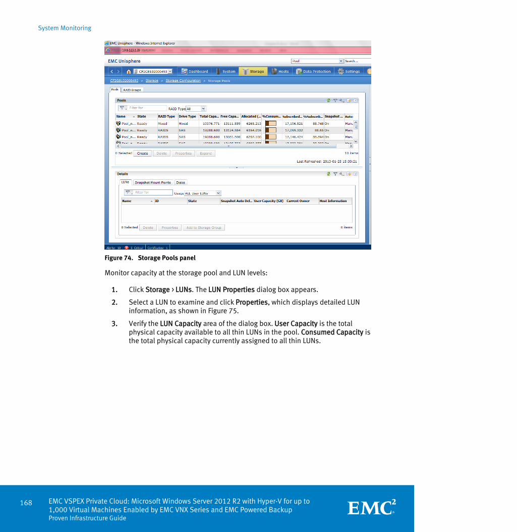
System Monitoring
168 EMC VSPEX Private Cloud: Microsoft Windows Server 2012 R2 with Hyper-V for up to 1,000 Virtual Machines Enabled by EMC VNX Series and EMC Powered Backup Proven Infrastructure Guide
Figure 74. Storage Pools panel
Monitor capacity at the storage pool and LUN levels: 1. Click Storage > LUNs. The LUN Properties dialog box appears.
2. Select a LUN to examine and click Properties, which displays detailed LUN information, as shown in Figure 75.
3. Verify the LUN Capacity area of the dialog box. User Capacity is the total physical capacity available to all thin LUNs in the pool. Consumed Capacity is the total physical capacity currently assigned to all thin LUNs.
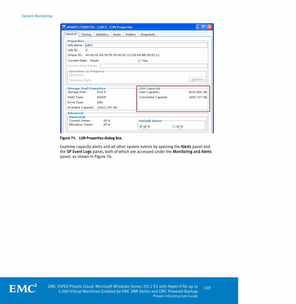
System Monitoring
EMC VSPEX Private Cloud: Microsoft Windows Server 2012 R2 with Hyper-V for up to 1,000 Virtual Machines Enabled by EMC VNX Series and EMC Powered Backup
Proven Infrastructure Guide
169
Figure 75. LUN Properties dialog box
Examine capacity alerts and all other system events by opening the Alerts panel and the SP Event Logs panel, both of which are accessed under the Monitoring and Alerts panel, as shown in Figure 76.
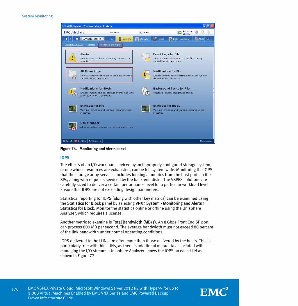
System Monitoring
170 EMC VSPEX Private Cloud: Microsoft Windows Server 2012 R2 with Hyper-V for up to 1,000 Virtual Machines Enabled by EMC VNX Series and EMC Powered Backup Proven Infrastructure Guide
Figure 76. Monitoring and Alerts panel
IOPS
The effects of an I/O workload serviced by an improperly configured storage system, or one whose resources are exhausted, can be felt system wide. Monitoring the IOPS that the storage array services includes looking at metrics from the host ports in the SPs, along with requests serviced by the back-end disks. The VSPEX solutions are carefully sized to deliver a certain performance level for a particular workload level. Ensure that IOPS are not exceeding design parameters.
Statistical reporting for IOPS (along with other key metrics) can be examined using the Statistics for Block panel by selecting VNX > System > Monitoring and Alerts > Statistics for Block. Monitor the statistics online or offline using the Unisphere Analyzer, which requires a license.
Another metric to examine is Total Bandwidth (MB/s). An 8 Gbps Front End SP port can process 800 MB per second. The average bandwidth must not exceed 80 percent of the link bandwidth under normal operating conditions.
IOPS delivered to the LUNs are often more than those delivered by the hosts. This is particularly true with thin LUNs, as there is additional metadata associated with managing the I/O streams. Unisphere Analyzer shows the IOPS on each LUN as shown in Figure 77.

System Monitoring
EMC VSPEX Private Cloud: Microsoft Windows Server 2012 R2 with Hyper-V for up to 1,000 Virtual Machines Enabled by EMC VNX Series and EMC Powered Backup
Proven Infrastructure Guide
171
Figure 77. IOPS on the LUNs
Certain RAID levels also impart write-penalties that create additional back-end IOPS. Examine the IOPS delivered to (and serviced from) the underlying physical disks, which can also be viewed in the Unisphere Analyzer in Figure 78. The guidelines for drive performance are
180 IOPS for 15k RPM SAS drives
120 IOPS for 10k RPM SAS drives
80 IOPS for NL SAS drives

System Monitoring
172 EMC VSPEX Private Cloud: Microsoft Windows Server 2012 R2 with Hyper-V for up to 1,000 Virtual Machines Enabled by EMC VNX Series and EMC Powered Backup Proven Infrastructure Guide
Figure 78. IOPS on the disks
Latency
Latency is the byproduct of delays in processing I/O requests. This context focuses on monitoring storage latency, specifically block-level I/O. Using similar procedures from a previous section, view the latency at the LUN level as shown in Figure 79.
Figure 79. Latency on the LUNs

System Monitoring
EMC VSPEX Private Cloud: Microsoft Windows Server 2012 R2 with Hyper-V for up to 1,000 Virtual Machines Enabled by EMC VNX Series and EMC Powered Backup
Proven Infrastructure Guide
173
Latency can be introduced anywhere along the I/O stream, from the application layer, through the transport, and out to the final storage devices. Determining precise causes of excessive latency requires a methodical approach.
Excessive latency in an FC network is uncommon. Unless there is a defective component such as an HBA or cable, delays introduced in the network fabric layer are normally a result of misconfigured switching fabrics. An overburdened storage array can also cause latency within an FC environment. Focus primarily on the LUNs and the underlying disk pools ability to service I/O requests. Requests that cannot be serviced are queued, which introduces latency.
The same paradigm applies to Ethernet-based protocols such as iSCSI and FCoE. However, additional factors come into place because these storage protocols use Ethernet as the underlying transport. Isolate the network traffic (either physical or logical) for storage, and preferably implement Quality of Service (QoS) in a shared or converged fabric. If network problems are not introducing excessive latency, examine the storage array. In addition to overburdened disks, excessive SP utilization can also introduce latency.
SP utilization levels greater than 80 percent indicate a potential problem. Background processes such as replication, deduplication, and snapshots all compete for SP resources. Monitor these processes to ensure they do not cause SP resource exhaustion. Possible mitigation techniques include staggering background jobs, setting replication limits, and adding more physical resources or rebalancing the I/O workloads. Growth may also mandate moving to more powerful hardware.
For SP metrics, examine the data under the SP tab of the Unisphere Analyzer, as shown in Figure 80. Review metrics such as Utilization %, Queue Length and Response Time (ms). High values for any of these metrics indicate the storage array is under duress and likely requires mitigation. EMC best practices recommend a threshold of 70% utilization, response time of 20 ms, and queue length of 10.
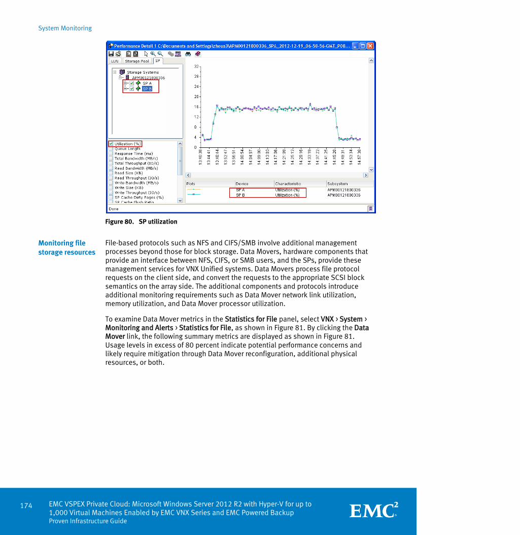
System Monitoring
174 EMC VSPEX Private Cloud: Microsoft Windows Server 2012 R2 with Hyper-V for up to 1,000 Virtual Machines Enabled by EMC VNX Series and EMC Powered Backup Proven Infrastructure Guide
Figure 80. SP utilization
File-based protocols such as NFS and CIFS/SMB involve additional management processes beyond those for block storage. Data Movers, hardware components that provide an interface between NFS, CIFS, or SMB users, and the SPs, provide these management services for VNX Unified systems. Data Movers process file protocol requests on the client side, and convert the requests to the appropriate SCSI block semantics on the array side. The additional components and protocols introduce additional monitoring requirements such as Data Mover network link utilization, memory utilization, and Data Mover processor utilization.
To examine Data Mover metrics in the Statistics for File panel, select VNX > System > Monitoring and Alerts > Statistics for File, as shown in Figure 81. By clicking the Data Mover link, the following summary metrics are displayed as shown in Figure 81. Usage levels in excess of 80 percent indicate potential performance concerns and likely require mitigation through Data Mover reconfiguration, additional physical resources, or both.
Monitoring file storage resources
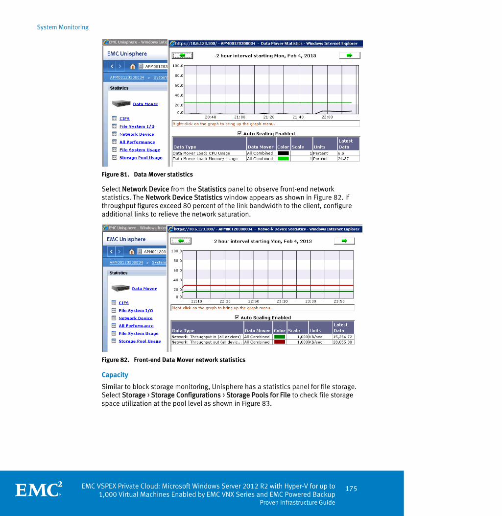
System Monitoring
EMC VSPEX Private Cloud: Microsoft Windows Server 2012 R2 with Hyper-V for up to 1,000 Virtual Machines Enabled by EMC VNX Series and EMC Powered Backup
Proven Infrastructure Guide
175
Figure 81. Data Mover statistics
Select Network Device from the Statistics panel to observe front-end network statistics. The Network Device Statistics window appears as shown in Figure 82. If throughput figures exceed 80 percent of the link bandwidth to the client, configure additional links to relieve the network saturation.
Figure 82. Front-end Data Mover network statistics
Capacity
Similar to block storage monitoring, Unisphere has a statistics panel for file storage. Select Storage > Storage Configurations > Storage Pools for File to check file storage space utilization at the pool level as shown in Figure 83.

System Monitoring
176 EMC VSPEX Private Cloud: Microsoft Windows Server 2012 R2 with Hyper-V for up to 1,000 Virtual Machines Enabled by EMC VNX Series and EMC Powered Backup Proven Infrastructure Guide
Figure 83. Storage Pools for File panel
Monitor capacity at the pool and file system levels. 1. Select Storage > File Systems. The File Systems window appears, as shown in
Figure 84.
Figure 84. File Systems panel
2. Select a file system to examine and click Properties, which displays detailed file system information, as shown in Figure 85.
3. Examine the File Storage area for Used and Free capacity.

System Monitoring
EMC VSPEX Private Cloud: Microsoft Windows Server 2012 R2 with Hyper-V for up to 1,000 Virtual Machines Enabled by EMC VNX Series and EMC Powered Backup
Proven Infrastructure Guide
177
Figure 85. File System Properties window
IOPS
In addition to monitoring block storage IOPS, Unisphere also provides the ability to monitor file system IOPS. Select System > Monitoring and Alerts > Statistics for File > File System I/O as shown in Figure 86.

System Monitoring
178 EMC VSPEX Private Cloud: Microsoft Windows Server 2012 R2 with Hyper-V for up to 1,000 Virtual Machines Enabled by EMC VNX Series and EMC Powered Backup Proven Infrastructure Guide
Figure 86. File System I/O Statistics window
Latency
To observe file system latency, select System > Monitoring and Alerts > Statistics for File > All Performance in Unisphere, and examine the value for CIFS:Ops/sec as shown in Figure 87.

System Monitoring
EMC VSPEX Private Cloud: Microsoft Windows Server 2012 R2 with Hyper-V for up to 1,000 Virtual Machines Enabled by EMC VNX Series and EMC Powered Backup
Proven Infrastructure Guide
179
Figure 87. CIFS Statistics window
Consistent and thorough monitoring of the VSPEX Proven Infrastructure is a best practice. Having baseline performance data helps to identify problems, while monitoring key system metrics helps to ensure that the system functions optimally and within designed parameters. The monitoring process can extend through integration with automation and orchestration tools from key partners such as Microsoft with its System Center suite of products.
Summary

EMC VSPEX Private Cloud: Microsoft Windows Server 2012 R2 with Hyper-V for up to 1,000 Virtual Machines Enabled by EMC VNX Series and EMC Powered Backup
Proven Infrastructure Guide
181
Chapter 8 Validation with Microsoft Fast
Track v3
This chapter presents the following topics:
Overview .................................................................................................. 182
Business case for validation ..................................................................... 182
Process requirements ............................................................................... 183
Additional resources ................................................................................ 185

Validation with Microsoft Fast Track v3
182 EMC VSPEX Private Cloud: Microsoft Windows Server 2012 R2 with Hyper-V for up to 1,000 Virtual Machines Enabled by EMC VNX Series and EMC Powered Backup Proven Infrastructure Guide
Overview
The Microsoft Hyper-V Fast Track Program is a reference architecture validation framework designed by Microsoft to validate end-to-end virtualization solutions comprised of Microsoft software products. These software products have been tightly integrated and tested with specific hardware components, while being built and configured according to best practices defined by Microsoft and the hardware vendors. Customers receive a fully built, read-to-run solution at their site. Microsoft handles primary support in conjunction with the solution owner (hardware vendors and/or system integrators) to ensure end-to-end solution support.
Unlike the VSPEX Proven Infrastructure solutions, which offer partners the flexibility to choose the solution components, the Microsoft Hyper-V Fast Track Program are locked configurations based on specific end-to-end architectures. Similar to the Windows Logo Program, any significant changes (such as a different HBA or BIOS) invalidate the architecture unless Microsoft revalidates the configuration.
VSPEX Proven Infrastructure solutions provide a valuable platform to serve as potential Microsoft Hyper-V Fast Track Program validated solutions, because much of the effort, such sizing and performance validation, has been completed by EMC. Customers can also benefit from a solution that has been thoroughly tested, validated, and approved by Microsoft. This section describes the steps for EMC VSPEX partners to guide a VSPEX Proven Infrastructure solution through the Microsoft Hyper-V Fast Track Program.
Business case for validation
The release of Microsoft Windows Server 2012 introduces significant product enhancements, and is the first generally available cloud-optimized server operating system. Microsoft identified key areas or pillars to focus on, including:
Continuous availability
Virtualization
Performance
Additionally, the release of the Microsoft System Center 2012 SP1 product suite introduces powerful, flexible new tools to integrate with the new features of Windows Server 2012. System Center Orchestrator, Virtual Machine Manager, Operations Manager, and Data Protection Manager provide customers the tools to cohesively build and manage virtualized cloud infrastructures.
The Microsoft Hyper-V Fast Track Program incorporates these products into a pre-built, bundled cloud solution based on collective best practices. This eliminates design guesswork and implementation problems, and enables organizations to implement cloud-based solutions rapidly within their IT infrastructure. Furthermore, since the end-to-end configuration is tested and validated, customers avoid many of the issues in a complex, multi-tiered environment such as driver or firmware incompatibilities.

Validation with Microsoft Fast Track v3
EMC VSPEX Private Cloud: Microsoft Windows Server 2012 R2 with Hyper-V for up to 1,000 Virtual Machines Enabled by EMC VNX Series and EMC Powered Backup
Proven Infrastructure Guide
183
EMC VSPEX partners that certify VSPEX Proven Infrastructures in the Microsoft Hyper-V Fast Track Program can create additional revenue streams from the services that comprise virtualization solutions. Partners can also use the VSPEX labs to validate their Microsoft Hyper-V Fast Track Program solution, using EMC expertise and reducing hardware requirements.
Process requirements
Solution validation for the Microsoft Hyper-V Fast Track Program is a significant endeavor. Using a VSPEX Proven Infrastructure solution as a basis eliminates a significant portion of the required work. Any VSPEX Proven Infrastructure that uses Microsoft Windows Server 2012 (or later) as the hypervisor is a viable candidate.
An EMC VSPEX partner must also be a Microsoft Gold partner. Obtain Microsoft Hyper-V Fast Track Program v3 documentation and program guidelines directly from Microsoft by sending a request to the following alias: [email protected]. Upon receipt, thoroughly review the documentation and program requirements to become familiar with the process.
There are certain support obligations defined in the Microsoft Hyper-V Fast Track Program. Contact Microsoft, or refer to program documentation for further details.
Select any VSPEX Proven Infrastructure solution based on Microsoft Windows Server 2012.
After choosing the base VSPEX Proven Infrastructure, partners must define additional architectural requirements to comply with the Microsoft Hyper-V Fast Track Program guidelines and requirements. Program documentation classifies these components as described in Table 34.
Table 34. Hyper-V Fast Track component classification
Icon Level Description
Mandatory Required to pass Microsoft validation.
Recommend Optional. This is an industry-standard recommendation and is not required to pass the Microsoft validation.
Optional Optional. Presents an alternate method to consider and is not
required to pass the Microsoft validation.
Partners must ensure that all mandatory components are included in the solution. EMC strongly advises partners to include recommended components to ensure the solution is robust and competitive.
Partners must make the following changes to a VSPEX Proven Infrastructure. All hardware components must be logo certified for Windows Server 2012. Refer to
Step 1: Core prerequisites
Step 2: Select the VSPEX Proven Infrastructure platform
Step 3: Define additional Microsoft Hyper-V Fast Track Program components

Validation with Microsoft Fast Track v3
184 EMC VSPEX Private Cloud: Microsoft Windows Server 2012 R2 with Hyper-V for up to 1,000 Virtual Machines Enabled by EMC VNX Series and EMC Powered Backup Proven Infrastructure Guide
the Windows Service Catalog website for device certification information. Use the WHCK process and the SysDev Dashboard portal as starting points for the certification process, and send proof of certification to the Microsoft Hyper-V Fast Track Program Team for review.
Provide an SKU, part number, or other simple and efficient process to purchase or resell the solution. Send details of the ordering process to the Microsoft Hyper-V Fast Track Program Team for review.
Servers must meet the following minimum requirements:
Two to four server nodes with clustering installed (cluster nodes).
Dual processor sockets, with 6 cores per socket (12 cores total).
32 GB RAM (4 GB per virtual machine and management host).
1 Gigabyte Ethernet (GbE) cluster interconnect.
Additional network isolation is required for cluster heartbeat traffic. Ensure the environment meets the following minimum network requirements:
Two physically separate networks. The cluster heartbeat network must be on a distinctly separate subnet from the hosted network traffic.
1 GbE, or greater, network adapter for internal communications, and 1 GbE, or greater, network adapter for external LAN communications for each node.
1 GbE, or greater, network speed for Live Migration traffic and cluster communication. EMC recommends using a 10 GbE network dedicated to Live Migration.
Do not share the virtual machine network adapter with the host operating system.
EMC and Microsoft do not support configurations with a single network connection.
Configure Network teaming so that:
The solution can withstand the loss of any single adapter without losing server connectivity.
The solution uses NIC teaming to provide high availability for the virtual machine networks. Microsoft supports third party teaming or Microsoft teaming.
Create a detailed bill of materials that includes hardware manufacturer, model, firmware, BIOS, and driver versions, and vendor part number for:
Servers
HBAs
Switches
Storage arrays
Software
Any other major components
Step 4: Build a detailed bill of materials

Validation with Microsoft Fast Track v3
EMC VSPEX Private Cloud: Microsoft Windows Server 2012 R2 with Hyper-V for up to 1,000 Virtual Machines Enabled by EMC VNX Series and EMC Powered Backup
Proven Infrastructure Guide
185
Install and configure the end-to-end environment. Run the Windows Cluster Validation Tool to verify the environment configuration, and Failover Clustering support. Send the results of this test to the Microsoft Hyper-V Fast Track Program Team for review. Refer to Validate Hardware for a Windows Server 2012 Failover Cluster for more information about the Windows Cluster Validation Tool.
Use the available solution template from the Microsoft Hyper-V Fast Track Program Team, or create a solution document based on the appropriate VSPEX Proven Infrastructure Guide. Add the additional required content per step three above, and then submit the final solution document to Microsoft and EMC for posting. An example solution created by Cisco and EMC, which follows the Microsoft Hyper-V Fast Track Program v2 guidelines, is available at Cisco Solutions for VSPEX
Additional resources
Microsoft Hyper-V Fast Track Program v3 documentation is only available for Microsoft partners, although some material exists on the Microsoft Partner Portal, TechNet, and various Microsoft blog sites. For the best results, contact the Microsoft Hyper-V Fast Track Program v3 Partner Program Management Team via their email alias at [email protected]. Alternatively, Microsoft partners can work through their Microsoft Technical Account Managers (TAMs). The public website is Private Cloud Fast Track.
Step 5: Test the environment
Step 6: Document and publish the solution


EMC VSPEX Private Cloud: Microsoft Windows Server 2012 R2 with Hyper-V for up to 1,000 Virtual Machines Enabled by EMC VNX Series and EMC Powered Backup
Proven Infrastructure Guide
187
Appendix A Bill of Materials
This appendix presents the following topic:
Bill of materials ...................................................................................................... 188
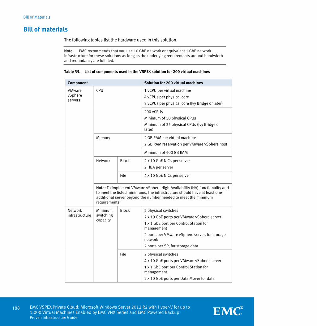
Bill of Materials
188 EMC VSPEX Private Cloud: Microsoft Windows Server 2012 R2 with Hyper-V for up to 1,000 Virtual Machines Enabled by EMC VNX Series and EMC Powered Backup Proven Infrastructure Guide
Bill of materials
The following tables list the hardware used in this solution.
Note: EMC recommends that you use 10 GbE network or equivalent 1 GbE network infrastructure for these solutions as long as the underlying requirements around bandwidth and redundancy are fulfilled.
Table 35. List of components used in the VSPEX solution for 200 virtual machines
Component Solution for 200 virtual machines
VMware vSphere servers
CPU 1 vCPU per virtual machine
4 vCPUs per physical core
8 vCPUs per physical core (Ivy Bridge or later)
200 vCPUs
Minimum of 50 physical CPUs
Minimum of 25 physical CPUs (Ivy Bridge or later)
Memory 2 GB RAM per virtual machine
2 GB RAM reservation per VMware vSphere host
Minimum of 400 GB RAM
Network
Block 2 x 10 GbE NICs per server
2 HBA per server
File 4 x 10 GbE NICs per server
Note: To implement VMware vSphere High-Availability (HA) functionality and to meet the listed minimums, the infrastructure should have at least one additional server beyond the number needed to meet the minimum requirements.
Network infrastructure
Minimum switching capacity
Block 2 physical switches
2 x 10 GbE ports per VMware vSphere server
1 x 1 GbE port per Control Station for management
2 ports per VMware vSphere server, for storage network
2 ports per SP, for storage data
File 2 physical switches
4 x 10 GbE ports per VMware vSphere server
1 x 1 GbE port per Control Station for management
2 x 10 GbE ports per Data Mover for data

Bill of Materials
EMC VSPEX Private Cloud: Microsoft Windows Server 2012 R2 with Hyper-V for up to 1,000 Virtual Machines Enabled by EMC VNX Series and EMC Powered Backup
Proven Infrastructure Guide
189
Component Solution for 200 virtual machines
EMC Backup Avamar Refer to EMC Backup and Recovery Options for VSPEX Private Clouds White Paper
Data Domain Refer to EMC Backup and Recovery Options for VSPEX Private Clouds White Paper
EMC VNX series storage array
Block EMC VNX5200
1 x 1 GbE interface per Control Station for management
1 x 1 GbE interface per SP for management
2 front end ports per SP
75 x 600 GB 15k rpm 3.5-inch SAS drives
4 x 200 GB flash drives
3 x 600 GB 15k rpm 3.5-inch SAS drives as hot spares
1 x 200 GB flash drive as a hot spare
File EMC VNX5200
2 Data Movers (active / standby)
2 x 10 GbE interfaces per Data Mover
1 x 1 GbE interface per Control Station for management
1 x 1 GbE interface per SP for management
75 x 600 GB 15k rpm 3.5-inch SAS drives
4 x 200 GB flash drives.
3 x 600 GB 15k rpm 3.5-inch SAS drives as hot spares
1 x 200 GB flash drive as a hot spare.
Shared infrastructure
In most cases, a customer environment already has infrastructure services such as Active Directory, DNS, and other services configured. The setup of these services is beyond the scope of this document.
If implemented without existing infrastructure, the new minimum requirements are:
2 physical servers
16 GB RAM per server
4 processor cores per server
2 x 1 GbE ports per server
Note: These services can be migrated into VSPEX post-deployment; however, they must exist before VSPEX can be deployed.
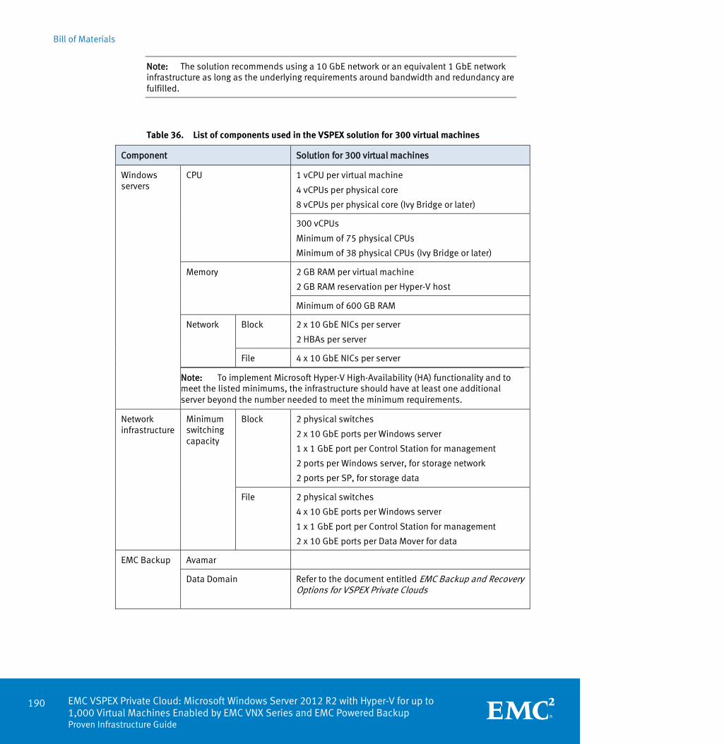
Bill of Materials
190 EMC VSPEX Private Cloud: Microsoft Windows Server 2012 R2 with Hyper-V for up to 1,000 Virtual Machines Enabled by EMC VNX Series and EMC Powered Backup Proven Infrastructure Guide
Note: The solution recommends using a 10 GbE network or an equivalent 1 GbE network infrastructure as long as the underlying requirements around bandwidth and redundancy are fulfilled.
Table 36. List of components used in the VSPEX solution for 300 virtual machines
Component Solution for 300 virtual machines
Windows servers
CPU 1 vCPU per virtual machine
4 vCPUs per physical core
8 vCPUs per physical core (Ivy Bridge or later)
300 vCPUs
Minimum of 75 physical CPUs
Minimum of 38 physical CPUs (Ivy Bridge or later)
Memory 2 GB RAM per virtual machine
2 GB RAM reservation per Hyper-V host
Minimum of 600 GB RAM
Network Block 2 x 10 GbE NICs per server
2 HBAs per server
File 4 x 10 GbE NICs per server
Note: To implement Microsoft Hyper-V High-Availability (HA) functionality and to meet the listed minimums, the infrastructure should have at least one additional server beyond the number needed to meet the minimum requirements.
Network infrastructure
Minimum switching capacity
Block 2 physical switches
2 x 10 GbE ports per Windows server
1 x 1 GbE port per Control Station for management
2 ports per Windows server, for storage network
2 ports per SP, for storage data
File 2 physical switches
4 x 10 GbE ports per Windows server
1 x 1 GbE port per Control Station for management
2 x 10 GbE ports per Data Mover for data
EMC Backup Avamar
Data Domain Refer to the document entitled EMC Backup and Recovery Options for VSPEX Private Clouds
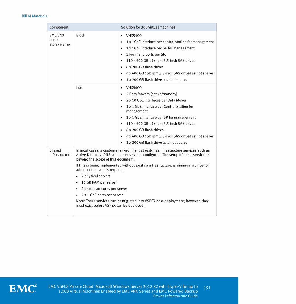
Bill of Materials
EMC VSPEX Private Cloud: Microsoft Windows Server 2012 R2 with Hyper-V for up to 1,000 Virtual Machines Enabled by EMC VNX Series and EMC Powered Backup
Proven Infrastructure Guide
191
Component Solution for 300 virtual machines
EMC VNX series storage array
Block VNX5400
1 x 1GbE interface per control station for management
1 x 1GbE interface per SP for management
2 Front End ports per SP.
110 x 600 GB 15k rpm 3.5-inch SAS drives
6 x 200 GB flash drives.
4 x 600 GB 15k rpm 3.5-inch SAS drives as hot spares
1 x 200 GB flash drive as a hot spare.
File VNX5400
2 Data Movers (active/standby)
2 x 10 GbE interfaces per Data Mover
1 x 1 GbE interface per Control Station for management
1 x 1 GbE interface per SP for management
110 x 600 GB 15k rpm 3.5-inch SAS drives
6 x 200 GB flash drives.
4 x 600 GB 15k rpm 3.5-inch SAS drives as hot spares
1 x 200 GB flash drive as a hot spare.
Shared infrastructure
In most cases, a customer environment already has infrastructure services such as Active Directory, DNS, and other services configured. The setup of these services is beyond the scope of this document.
If this is being implemented without existing infrastructure, a minimum number of additional servers is required:
2 physical servers
16 GB RAM per server
4 processor cores per server
2 x 1 GbE ports per server
Note: These services can be migrated into VSPEX post-deployment; however, they must exist before VSPEX can be deployed.

Bill of Materials
192 EMC VSPEX Private Cloud: Microsoft Windows Server 2012 R2 with Hyper-V for up to 1,000 Virtual Machines Enabled by EMC VNX Series and EMC Powered Backup Proven Infrastructure Guide
Table 37. List of components used in the VSPEX solution for 600 virtual machines
Component Solution for 600 virtual machines
Windows servers
CPU 1 vCPU per virtual machine
4 vCPUs per physical core
8 vCPUs per physical core (Ivy Bridge or later)
600 vCPUs
Minimum of 150 Physical CPUs
Minimum of 75 physical CPUs (Ivy Bridge or later)
Memory 2 GB RAM per virtual machine
2 GB RAM reservation per Hyper-V host
Minimum of 1200 GB RAM
Network Block 2 x 10 GbE NICs per server
2 HBA per server
File 4 x 10 GbE NICs per server
Note: To implement Microsoft Hyper-V High-Availability (HA) functionality and to meet the listed minimums, the infrastructure should have at least one additional server beyond the number needed to meet the minimum requirements.
Network infrastructure
Minimum switching capacity
Block 2 physical switches
2 x 10 GbE ports per Windows server
1 x 1 GbE port per Control Station for management
2 ports per Windows server, for storage network
2 ports per SP, for storage data
File 2 physical switches
4 x 10 GbE ports per Windows server
1 x 1 GbE port per Control Station for management
2 x 10 GbE ports per Data Mover for data
EMC Backup Avamar
Data Domain Referto the document EMC Backup and Recovery Options for VSPEX Private Clouds
EMC VNX series storage array
Block VNX5600
1 x 1GbE interface per Control Station for management
1 x 1GbE interface per SP for management
2 Front End ports per SP.
220 x 600 GB 15k rpm 3.5-inch SAS drives
10x 200 GB flash drives.
8 x 600 GB 15k rpm 3.5-inch SAS drives as hot spares
1 x 200 GB flash drive as a hot spare.

Bill of Materials
EMC VSPEX Private Cloud: Microsoft Windows Server 2012 R2 with Hyper-V for up to 1,000 Virtual Machines Enabled by EMC VNX Series and EMC Powered Backup
Proven Infrastructure Guide
193
Component Solution for 600 virtual machines
File VNX5600
2 Data Movers (active/standby)
2 x 10 GbE interfaces per Data Mover
1 x 1 GbE interface per Control Station for management
1 x 1 GbE interface per SP for management
220 x 600 GB 15k rpm 3.5-inch SAS drives
10 x 200 GB flash drives
8 x 600 GB 15k rpm 3.5-inch SAS drives as hot spares
1 x 200 GB flash drive as a hot spare
Shared infrastructure
In most cases, a customer environment already has infrastructure services such as Active Directory, DNS, and other services configured. The setup of these services is beyond the scope of this document.
If this is being implemented without existing infrastructure, a minimum number of additional servers is required:
2 physical servers
16 GB RAM per server
4 processor cores per server
2 x 1 GbE ports per server
Note: These services can be migrated into VSPEX post-deployment; however, they must exist before VSPEX can be deployed.

Bill of Materials
194 EMC VSPEX Private Cloud: Microsoft Windows Server 2012 R2 with Hyper-V for up to 1,000 Virtual Machines Enabled by EMC VNX Series and EMC Powered Backup Proven Infrastructure Guide
Table 38. List of components used in the VSPEX solution for 1,000 virtual machines
Component Solution for 1,000 virtual machines
Windows servers
CPU 1 vCPU per virtual machine
4 vCPUs per physical core
8 vCPUs per physical core (Ivy Bridge or later)
1,000 vCPUs
Minimum of 250 physical CPUs
Minimum of 125 physical CPUs (Ivy Bridge or later)
Memory 2 GB RAM per virtual machine
2 GB RAM reservation per Hyper-V host
Minimum of 2000 GB RAM
Network Block 2 x 10 GbE NICs per server
2 HBA per server
File 4 x 10 GbE NICs per server
Note: To implement Microsoft Hyper-V High-Availability (HA) functionality and to meet the listed minimums, the infrastructure should have at least one additional server beyond the number needed to meet the minimum requirements.
Network infrastructure
Minimum switching capacity
Block 2 physical switches
2 x 10 GbE ports per Windows server
1 x 1 GbE port per Control Station for management
2 ports per Windows server, for storage network
2 ports per SP, for storage data
File 2 physical switches
4 x 10 GbE ports per Windows server
1 x 1 GbE port per Control Station for management
2 x 10 GbE ports per Data Mover for data
EMC Backup Avamar
Data Domain Refer to the white paper entitled EMC Backup and Recovery Options for VSPEX Private Clouds.
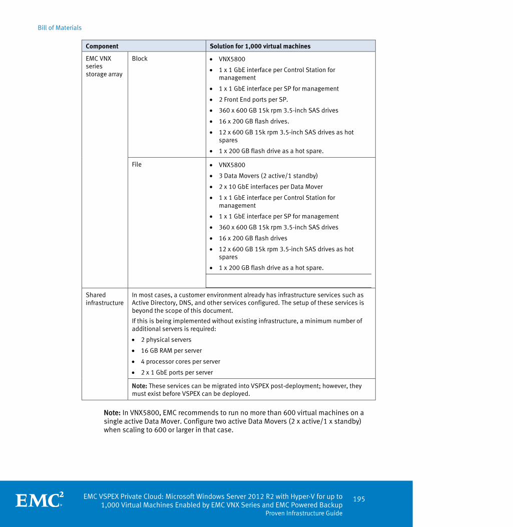
Bill of Materials
EMC VSPEX Private Cloud: Microsoft Windows Server 2012 R2 with Hyper-V for up to 1,000 Virtual Machines Enabled by EMC VNX Series and EMC Powered Backup
Proven Infrastructure Guide
195
Component Solution for 1,000 virtual machines
EMC VNX series storage array
Block VNX5800
1 x 1 GbE interface per Control Station for management
1 x 1 GbE interface per SP for management
2 Front End ports per SP.
360 x 600 GB 15k rpm 3.5-inch SAS drives
16 x 200 GB flash drives.
12 x 600 GB 15k rpm 3.5-inch SAS drives as hot spares
1 x 200 GB flash drive as a hot spare.
File VNX5800
3 Data Movers (2 active/1 standby)
2 x 10 GbE interfaces per Data Mover
1 x 1 GbE interface per Control Station for management
1 x 1 GbE interface per SP for management
360 x 600 GB 15k rpm 3.5-inch SAS drives
16 x 200 GB flash drives
12 x 600 GB 15k rpm 3.5-inch SAS drives as hot spares
1 x 200 GB flash drive as a hot spare.
Shared infrastructure
In most cases, a customer environment already has infrastructure services such as Active Directory, DNS, and other services configured. The setup of these services is beyond the scope of this document.
If this is being implemented without existing infrastructure, a minimum number of additional servers is required:
2 physical servers
16 GB RAM per server
4 processor cores per server
2 x 1 GbE ports per server
Note: These services can be migrated into VSPEX post-deployment; however, they must exist before VSPEX can be deployed.
Note: In VNX5800, EMC recommends to run no more than 600 virtual machines on a single active Data Mover. Configure two active Data Movers (2 x active/1 x standby) when scaling to 600 or larger in that case.

Bill of Materials
196 EMC VSPEX Private Cloud: Microsoft Windows Server 2012 R2 with Hyper-V for up to 1,000 Virtual Machines Enabled by EMC VNX Series and EMC Powered Backup Proven Infrastructure Guide
EMC VSPEX Private Cloud: Microsoft Windows Server 2012 R2 with Hyper-V for up to 1,000 Virtual Machines Enabled by EMC VNX Series and EMC Powered Backup
Proven Infrastructure Guide
197
Appendix B Customer Configuration Data Sheet
This appendix presents the following topic:
Customer configuration data sheet ........................................................................ 198
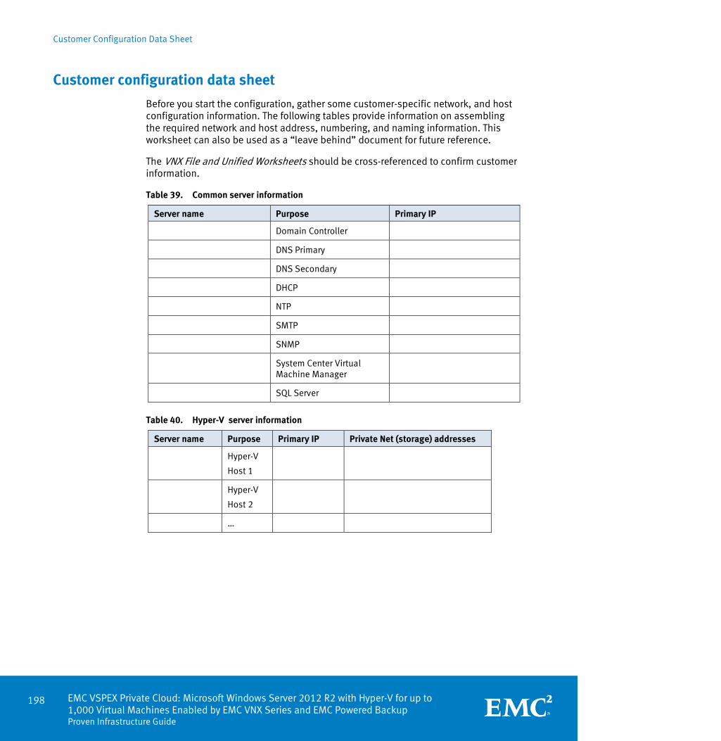
Customer Configuration Data Sheet
198 EMC VSPEX Private Cloud: Microsoft Windows Server 2012 R2 with Hyper-V for up to 1,000 Virtual Machines Enabled by EMC VNX Series and EMC Powered Backup Proven Infrastructure Guide
Customer configuration data sheet
Before you start the configuration, gather some customer-specific network, and host configuration information. The following tables provide information on assembling the required network and host address, numbering, and naming information. This worksheet can also be used as a “leave behind” document for future reference.
The VNX File and Unified Worksheets should be cross-referenced to confirm customer information.
Table 39. Common server information
Server name Purpose Primary IP
Domain Controller
DNS Primary
DNS Secondary
DHCP
NTP
SMTP
SNMP
System Center Virtual Machine Manager
SQL Server
Table 40. Hyper-V server information
Server name Purpose Primary IP Private Net (storage) addresses
Hyper-V
Host 1
Hyper-V
Host 2
…

Customer Configuration Data Sheet
EMC VSPEX Private Cloud: Microsoft Windows Server 2012 R2 with Hyper-V for up to 1,000 Virtual Machines Enabled by EMC VNX Series and EMC Powered Backup
Proven Infrastructure Guide
199
Table 41. Array information
Array name
Admin account
Management IP
Storage pool name
Datastore name
Block FC WWPN
FCOE WWPN
iSCSI IQN
iSCSI Port IP
File CIFS server IP
Table 42. Network infrastructure information
Name Purpose IP Subnet mask Default gateway
Ethernet Switch 1
Ethernet Switch 2
…

Customer Configuration Data Sheet
200 EMC VSPEX Private Cloud: Microsoft Windows Server 2012 R2 with Hyper-V for up to 1,000 Virtual Machines Enabled by EMC VNX Series and EMC Powered Backup Proven Infrastructure Guide
Table 43. VLAN information
Name Network Purpose VLAN ID Allowed Subnets
Virtual machine networking managements
iSCSI storage network (block)
CIFS storage network (file)
Live Migration (optional)
Public (client access)
Table 44. Service accounts
Account Purpose Password (optional, secure appropriately)
Windows Server administrator
Array administrator
SCVMM administator
SQL Server administrator

EMC VSPEX Private Cloud: Microsoft Windows Server 2012 R2 with Hyper-V for up to 1,000 Virtual Machines Enabled by EMC VNX Series and EMC Powered Backup
Proven Infrastructure Guide
201
Appendix C Server Resources Component Worksheet
This appendix presents the following topic:
Server resources component worksheet................................................................. 202

Server Resources Component Worksheet
202 EMC VSPEX Private Cloud: Microsoft Windows Server 2012 R2 with Hyper-V for up to 1,000 Virtual Machines Enabled by EMC VNX Series and EMC Powered Backup Proven Infrastructure Guide
Server resources component worksheet
Table 45. Blank worksheet for determining server resources
Server resources Storage resources
Application CPU
(virtual CPUs)
Memory (GB)
IOPS Capacity (GB)
Reference virtual machines
Resource requirements
N/A
Equivalent reference virtual machines
Resource requirements
N/A
Equivalent reference virtual machines
Resource requirements
N/A
Equivalent reference virtual machines
Resource requirements
N/A
Equivalent reference virtual machines
Total equivalent reference virtual machines
Server customization
Server component totals NA
Storage customization
Storage component totals NA
Storage component equivalent reference virtual machines NA
Total equivalent reference virtual machines - storage

References
EMC VSPEX Private Cloud: Microsoft Windows Server 2012 R2 with Hyper-V for up to 1,000 Virtual Machines Enabled by EMC VNX Series and EMC Powered Backup
Proven Infrastructure Guide
203
Appendix D References
This appendix presents the following topic:
References ............................................................................................................. 204

References
204 EMC VSPEX Private Cloud: Microsoft Windows Server 2012 R2 with Hyper-V for up to 1,000 Virtual Machines Enabled by EMC VNX Series and EMC Powered Backup Proven Infrastructure Guide
References
The following documents, available on EMC Online Support provide additional and relevant information. If you do not have access to a document, contact your EMC representative.
EMC Storage Integrator (ESI) 2.1 for Windows Suite
EMC VNX Virtual Provisioning Applied Technology
VNX FAST Cache: A Detailed Review
Introduction to EMC XtremCache
VNX5400 Unified Installation Guide
VNX5600 Unified Installation Guide
VNX5800 Unified Installation Guide
Using EMC VNX Storage with Microsoft Windows Hyper-V
EMC VNX Unified Best Practice For Performance -Applied Best Practices Guide
Using VNX SnapSure
EMC Host Connectivity Guide for Windows
EMC VNX Series: Introduction to SMB 3.0 Support
Configuring and Managing CIFS on VNX
The following documents, located on the Microsoft website, provide additional and relevant information:
Installing the VMM Server
How to Add a Host Cluster to VMM
How to Create a Template from a Virtual Machine
Configuring a Remote Instance of SQL Server for VMM
Installing Virtual Machine Manager
Installing the VMM Administrator Console
Installing a VMM Agent Locally on a Host
Adding Hyper-V Hosts and Host Clusters to VMM
How to Create a Virtual Machine with a Blank Virtual Hard Disk to Create a Virtual Machine
How to Deploy a Virtual Machine
Installing Windows Server 2012
Use Cluster Shared Volumes in a Windows Server 2012 Failover Cluster
Hardware and Software Requirements for Installing SQL Server 2012
EMC documentation
Other documentation

References
EMC VSPEX Private Cloud: Microsoft Windows Server 2012 R2 with Hyper-V for up to 1,000 Virtual Machines Enabled by EMC VNX Series and EMC Powered Backup
Proven Infrastructure Guide
205
Installing SQL Server 2012
How to Install a VMM Management Server

References
206 EMC VSPEX Private Cloud: Microsoft Windows Server 2012 R2 with Hyper-V for up to 1,000 Virtual Machines Enabled by EMC VNX Series and EMC Powered Backup Proven Infrastructure Guide

EMC VSPEX Private Cloud: Microsoft Windows Server 2012 R2 with Hyper-V for up to 1,000 Virtual Machines Enabled by EMC VNX Series and EMC Powered Backup
Proven Infrastructure Guide
207
Appendix E About VSPEX
This appendix presents the following topic:
About VSPEX .......................................................................................................... 208

About VSPEX
208 EMC VSPEX Private Cloud: Microsoft Windows Server 2012 R2 with Hyper-V for up to 1,000 Virtual Machines Enabled by EMC VNX Series and EMC Powered Backup Proven Infrastructure Guide
About VSPEX
EMC has joined forces with the industry leading providers of IT infrastructure to create a complete virtualization solution that accelerates deployment of cloud infrastructure. Built with best-of-breed technologies, VSPEX enables faster deployment, more simplicity, greater choice, higher efficiency, and lower risk. Validation by EMC ensures predictable performance and enables customers to select technology that uses their existing IT infrastructure while eliminating planning, sizing, and configuration burdens. VSPEX provides a proven infrastructure for customers looking to gain the simplicity that is characteristic of truly converged infrastructures, while at the same time gaining more choice in individual solution components.
VSPEX solutions are proven by EMC, and packaged and sold exclusively by EMC channel partners. VSPEX provides channel partners with more opportunity, faster sales cycles, and end-to-end enablement. By working even more closely together, EMC and its channel partners can now deliver infrastructure that accelerates the journey to the cloud for even more customers.