EMC - content.amprobe.comcontent.amprobe.com/certifications/37XR-A_LVD.pdf · EMC TEST REPORT...
18
Report No.: TS08100065-EME Page 1 of 18 EMC TEST REPORT Report No.: TS08100065-EME Model No.: 37XR-A Issued Date: Jan. 12, 2009 Applicant: FLUKE CORP. 6920 Seaway Blvd, M/S 266D Everett, WA 98203 U.S.A. Test Method/ Standard: EN 61326-1: 2006 EN 61000-3-2: 2006 EN 61000-3-3: 1995+A1: 2001+A2: 2005 Test By: Intertek Testing Services Taiwan Ltd. No. 11, Lane 275, Ko-Nan 1 Street, Chia-Tung Li, Shiang-Shan District, Hsinchu City, Taiwan This test report consists of 18 pages in total. It may be duplicated completely for legal use with the allowance of the applicant. It shall not be reproduced except in full, without the written approval of Intertek Laboratory. The test result in this report only applies to the tested sample. The test report was prepared by: Sign on File Julie Wang/ Assistant These measurements were taken by: Sign on File Bell Huang/ Engineer The test report was reviewed by: Name Rico Deng Title Senior Engineer
Transcript of EMC - content.amprobe.comcontent.amprobe.com/certifications/37XR-A_LVD.pdf · EMC TEST REPORT...

Report No.: TS08100065-EME
Page 1 of 18
EMC
TEST REPORT
Report No.: TS08100065-EMEModel No.: 37XR-A Issued Date: Jan. 12, 2009
Applicant: FLUKE CORP. 6920 Seaway Blvd, M/S 266D Everett, WA 98203 U.S.A.
Test Method/ Standard:
EN 61326-1: 2006 EN 61000-3-2: 2006 EN 61000-3-3: 1995+A1: 2001+A2: 2005
Test By: Intertek Testing Services Taiwan Ltd. No. 11, Lane 275, Ko-Nan 1 Street, Chia-Tung Li, Shiang-Shan District, Hsinchu City, Taiwan
This test report consists of 18 pages in total. It may be duplicated completely for legal use with the allowance of the applicant. It shall not be reproduced except in full, without the written approval of Intertek Laboratory. The test result in this report only applies to the tested sample.
The test report was prepared by:
Sign on File Julie Wang/ Assistant
These measurements were taken by:
Sign on File Bell Huang/ Engineer
The test report was reviewed by:
Name Rico Deng Title Senior Engineer

Report No.: TS08100065-EME
Page 2 of 18
Table of Contents
1. General Information ..................................................................................................... 3 1.1 Identification of The EUT ...................................................................................... 3 1.2 Additional Information About The EUT ................................................................ 3 1.3 Peripherals Equipment............................................................................................ 3
2. Test Summary ............................................................................................................... 4
3. Test Specifications ........................................................................................................ 5 3.1 Standards ................................................................................................................ 5 3.2 Mode of operation during the test .......................................................................... 5 3.3 Performance criteria ............................................................................................... 6
4. CISPR 11 Radiated Emission Test................................................................................ 7 4.1 Operating Environment .......................................................................................... 7 4.2 Test Procedure ........................................................................................................ 7 4.3 Test Equipment ....................................................................................................... 8 4.4 Radiated Emission Limit ........................................................................................ 8 4.5 Uncertainty of Radiated Emission.......................................................................... 8 4.6 Radiated Emission Test Data .................................................................................. 9
5. IEC 61000-4-2 Electrostatic Discharge Immunity Test.............................................. 11 5.1 Operating Environment ........................................................................................ 11 5.2 Purpose ................................................................................................................. 11 5.3 Test Set-Up ........................................................................................................... 11 5.4 Test Conditions ..................................................................................................... 11 5.5 Test Equipment ..................................................................................................... 12 5.6 Test Result ............................................................................................................ 12
6. IEC 61000-4-3 Radiated, Radio-Frequency, Electromagnetic Field Immunity Test.............................................................................................................................. 13 6.1 Operating Environment ........................................................................................ 13 6.2 Purpose ................................................................................................................. 13 6.3 Test Set-Up ........................................................................................................... 13 6.4 Test Conditions ..................................................................................................... 13 6.5 Test Equipment ..................................................................................................... 14 6.6 Generation of The Electromagnetic Field ............................................................ 14 6.7 Test Results........................................................................................................... 15
Appendix A1: External photo of EUT............................................................................ 16 Appendix B1: Radiated Emission Test Set-up ............................................................... 18
Report No.: TS08100065-EME
Page 3 of 18
1. General Information
1.1 Identification of The EUT
Product: Digital Multimeter Model No.: 37XR-A Rated Power: DC 9 V from battery Power Cord: N/A Data Cable: N/A Sample receiving date: Sep. 23, 2008 Testing date: Oct. 15, 2008 ~ Jan. 08, 2009 Note 1: This report is for the exclusive use of Intertek's Client and is
provided pursuant to the agreement between Intertek and its Client. Intertek's responsibility and liability are limited to the terms and conditions of the agreement. Intertek assumes no liability to any party, other than to the Client in accordance with the agreement, for any loss, expense or damage occasioned by the use of this report. Only the Client is authorized to permit copying or distribution of this report and then only in its entirety. Any use of the Intertek name or one of its marks for the sale or advertisement of the tested material, product or service must first be approved in writing by Intertek. The observations and test results in this report are relevant only to the sample tested. This report by itself does not imply that the material, product, or service is or has ever been under an Intertek certification program.
Note 2: The test report only allows to be revised within three years from its original issued date unless further standard or the requirement was noticed.
Note 3: When determining the test conclusion, the Measurement Uncertainty of test has been considered.
1.2 Additional Information About The EUT The EUT is a Digital Multimeter. It has to fulfill the requirements of CISPR 11 emission relevant standards. For more detail features, please refer to user's Manual. 1.3 Peripherals Equipment
Resistance × 1
Report No.: TS08100065-EME
Page 4 of 18
2. Test Summary
Emission (EN 61326-1: 2006)
Standard Test Type Result Remarks
CISPR 11: 2003 Class B Radiated Test PASS Pass by -8.59 dB at 784.700 MHz
with antenna polarization Vertical
Immunity (EN 61326-1: 2006)
Standard Test Type Result Performance Criteria Test Judgment IEC 61000-4-2: 1995 +A1: 1998 +A2: 2000 ESD test PASS Criterion B Meets the requirements of
Performance Criterion A IEC 61000-4-3: 2006 +A1: 2007 RS test PASS Criterion A Meets the requirements of
Performance Criterion A
Remark: The EUT has been tested/evaluated and pass the above standards without modification.

Report No.: TS08100065-EME
Page 5 of 18
3. Test Specifications
3.1 Standards EN 61326-1: 2006 Electrical equipment for measurement, control and laboratory use ― EMC requirements Part 1: General requirements. EN 61000-3-2:2006 Electromagnetic compatibility- Part 3. Limits Section 2. Limits for harmonic current emissions (equipment input current ≤ 16 A per phase) EN 61000-3-3: 1995+A1: 2001+A2: 2005 Electromagnetic compatibility - Part 3. Limits Section 3. Limitation of voltage fluctuations and flicker in low-voltage supply systems for equipment with rated current ≤ 16 A CISPR 11: 2003 Limits and methods of measurement of radio disturbance characteristics of industrial, scientific and medical (ISM) radio-frequency equipment Since the EUT is not connected to AC source, directly the tests are not applicable for it. The following test items were exempted based on engineering judgment.
EN 61000-3-2 Harmonic test EN 61000-3-3 Flicker test IEC 61000-4-4 EFT test IEC 61000-4-5 Surge test IEC 61000-4-6 CS test IEC 61000-4-11 Dip test
3.2 Mode of operation during the test The EUT was supplied with DC 9 V from battery and tested in resistance function mode.
Report No.: TS08100065-EME
Page 6 of 18
3.3 Performance criteria
The performance criterias listed below are based on those regulated in the standard, specified by the manufacturer or derived from the product specification. Criteria A: During testing, normal performance within the specification limits. Criteria B: During testing, temporary degradation, or loss of function or performance which is self-recovering. Criteria C: During testing, temporary degradation, or loss of function or performance which requires operator intervention or system reset occurs.

Report No.: TS08100065-EME
Page 7 of 18
4. CISPR 11 Radiated Emission Test
4.1 Operating Environment
Temperature: 25 ℃ Atmospheric Pressure: 1023 hPa
Relative Humidity: 50 % Test Voltage: DC 9 V from battery
4.2 Test Procedure
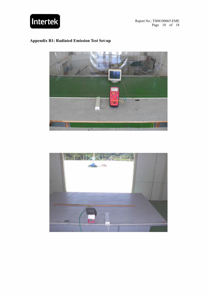
Radiated testing was performed at an 10 meter open area test site. The equipment under test were placed on a turntable top 0.8meter above ground. The table was 360 degrees to determine the position of the highest radiation. EUT is set 10 meters from the EMI receiving antenna, which is mounted on a variable height mast. The antenna height is varied between one meter and four meters above ground to find the maximum value of the field strength. Both horizontal polarization and vertical polarization of the antenna was set to conduct the measurement. The bandwidth was set on the EMI meter 120 kHz. The levels are quasi peak value readings. The frequency spectrum from 30MHz to 1000MHz was investigated.
EUT & Peripherals
0.8 meter
Ground Plane
Antenna Tower
Receiver Antenna
1.0~4.0 meter
10 meter
□
RF Test Receive

Report No.: TS08100065-EME
Page 8 of 18
4.3 Test Equipment
Equipment Brand Model No.
EMI Receiver Rohde & schwarz ESCS30
Bilog Antenna Schaffner CBL6112B Note: The above equipments are within the valid calibration period.
4.4 Radiated Emission Limit
Frequency (MHz) Distance(m) Class A Class B
30~230 10 40 30
230~1000 10 47 37 Note: 1. The tighter limit shall apply at the edge between two frequency bands. 2. Distance refers to the distance in meters between the measuring instrument antenna and the closet point of EUT. 4.5 Uncertainty of Radiated Emission
Expanded uncertainty (k=2) of radiated emission measurement is ±4.68 dB.

Report No.: TS08100065-EME
Page 9 of 18
4.6 Radiated Emission Test Data Polarity: Vertical Model No.: 37XR-A Test Condition: Resistance function mode
Remark: 1. Level (dBμV/m)= Factor (dB/m)+ Read Level (dBμV) 2. Factor = Antenna Factor (dB/m) + Cable Loss (dB) 3. Over Limit (Margin) (dB) = Level (dBμV/m) – Limit Line(dBμV/m)

Report No.: TS08100065-EME
Page 10 of 18
Polarity: Horizontal Model No.: 37XR-A Test Condition: Resistance function mode
Remark: 1. Level (dBμV/m)= Factor (dB/m)+ Read Level (dBμV) 2. Factor = Antenna Factor (dB/m) + Cable Loss (dB) 3. Over Limit (Margin) (dB) = Level (dBμV/m) – Limit Line(dBμV/m)

Report No.: TS08100065-EME
Page 11 of 18
5. IEC 61000-4-2 Electrostatic Discharge Immunity Test 5.1 Operating Environment
Temperature: 25 ℃ Atmospheric Pressure: 1023 hPa
Relative Humidity: 55 % Test Voltage: DC 9 V from battery
5.2 Purpose
The object of the test is to evaluate the ESD immunity performance of EUT. 5.3 Test Set-Up A horizontal coupling plane (HCP) was placed on a non-metallic table 0.8 m above a reference ground plane (RGP) and connected to it with a cable with two 470 kΩ resistors. The EUT was placed on an insulation sheet on the HCP and was operated according to the specified operating mode. A vertical coupling plane (VCP) was connected to the RGP with a cable with two 470 kΩ resistors. 5.4 Test Conditions Test level: Air discharge ------- +/- 8 kV Contact discharge ------- +/- 4 kV Single discharge at 1 second interval positive discharge and negative discharge

Report No.: TS08100065-EME
Page 12 of 18
5.5 Test Equipment
Equipment Manufacturer Model No.
Electrostatic Discharge System NoiseKen ESS-2002
Note: The above equipments are within the valid calibration period. 5.6 Test Result
Point of Discharge Applied Voltage
(kV)
Total No. ofDischarge
(Each Point)Result Criteria
Level Remark
±2 20 P A - Contact Test Point
±4 20 P A -
±2 20 P A -
±4 20 P A - Air Test Point
±8 20 P A -
±2 20 P A - VCP (4 sides) ±4 20 P A -
±2 20 P A - HCP (4 sides) ±4 20 P A -
Description
Contact Discharge: 6 test points Air Discharge Metallic Screws Plastic Screws Metallic Case Plastic Case (gap) Metallic Connect ports Plastic Connect ports Metallic Junctions Plastic Junctions Others: LED indicator
Panel Board Others:
Note: 1. “P” means the EUT pass the test. Note: 2. “-“ means not applicable

Report No.: TS08100065-EME
Page 13 of 18
6. IEC 61000-4-3 Radiated, Radio-Frequency, Electromagnetic Field Immunity
Test 6.1 Operating Environment
Temperature: 23 ℃ Atmospheric Pressure: 1023 hPa
Relative Humidity: 53 % Test Voltage: DC 9 V from battery
6.2 Purpose
This test method subjects the EUT to a power source of disturbance comprising electric and magnetic field, simulating those coming from intentional RF transmitters.
6.3 Test Set-Up The EUT was placed on a non-metallic table 0.8 meter above the reference ground plane (RGP) and was operated according to its specified operating mode. Ferrite tiles/absorbers were placed on the RGP between the EUT and the antenna to reduce the reflections from the RGP. The EUT and its cables were exposed for the electromagnetic field for 1.5m vertically and 1.5m horizontally. The distance between antenna and EUT is 3 meter. 6.4 Test Conditions
Test level Test field strength V/m Modulation
1 1 1 kHz 80% AM 2 3 1 kHz 80% AM 3 10 1 kHz 80% AM X Special 1 kHz 80% AM
The frequency steps : 1﹪, Log sweep Dwell time : 3 sec Frequency range : 80 MHz~1GHz, 1.4 GHz~2 GHz, 2 GHz~2.7 GHz
Test ports : Enclosure port Test field strength : 1 V/m & 3 V/m

Report No.: TS08100065-EME
Page 14 of 18
6.5 Test Equipment
Equipment Manufacture Model No. An-echoic chamber
7m×3m×3m Comtest Instrumentation 9708093
RF signal Generator Marconi 2023B
Dual Band RF Power Amplifier Kalmus 757LCB
High Power Microwave Amplifier Series MILMEGA AS0102-30
Bi-log Antenna EMCO 3141
RF Power Meter Boonton 4230
Power Sensor Boonton 51011-EMC
Power Sensor Boonton 51011-EMC
Field Probe Holaday HI-4422
Note: The above equipments are within the valid calibration period. 6.6 Generation of The Electromagnetic Field The electromagnetic field is generated from a computer controlled signal generator. The output power is amplified and then radiated from broadband log periodic antennas. For each sweep a pre-recorded empty chamber calibration file is used to establish the required field strength. When using these files the field strength inside an area of 1.5/1.0 m x 1.5m is in accordance with the standard.

Report No.: TS08100065-EME
Page 15 of 18
6.7 Test Results
Exposed Side: ⌧ Front ⌧ Left ⌧ Rear ⌧ Right H: Horizontal V: Vertical
Frequency (MHz)
Horizontal/Vertical Result Criteria
Level Remark
80 MHz to 1 GHz H P A 3 V/m
80 MHz to 1 GHz V P A 3 V/m
1.4 GHz to 2 GHz H P A 3 V/m
1.4 GHz to 2 GHz V P A 3 V/m
2 GHz to 2.7 GHz H P A 1 V/m
2 GHz to 2.7 GHz V P A 1 V/m
Note: 1. “P” means the EUT pass the test. Note: 2. “-“ means not applicable

Report No.: TS08100065-EME
Page 16 of 18
Appendix A1: External photo of EUT

Report No.: TS08100065-EME
Page 17 of 18
Report No.: TS08100065-EME
Page 18 of 18
Appendix B1: Radiated Emission Test Set-up