EMBRAER 135-145 - AUTOPILOT · The autopilot/yaw damper monitors continuously check autopilot...
40
EMBRAER 135/145 Autopilot
Transcript of EMBRAER 135-145 - AUTOPILOT · The autopilot/yaw damper monitors continuously check autopilot...
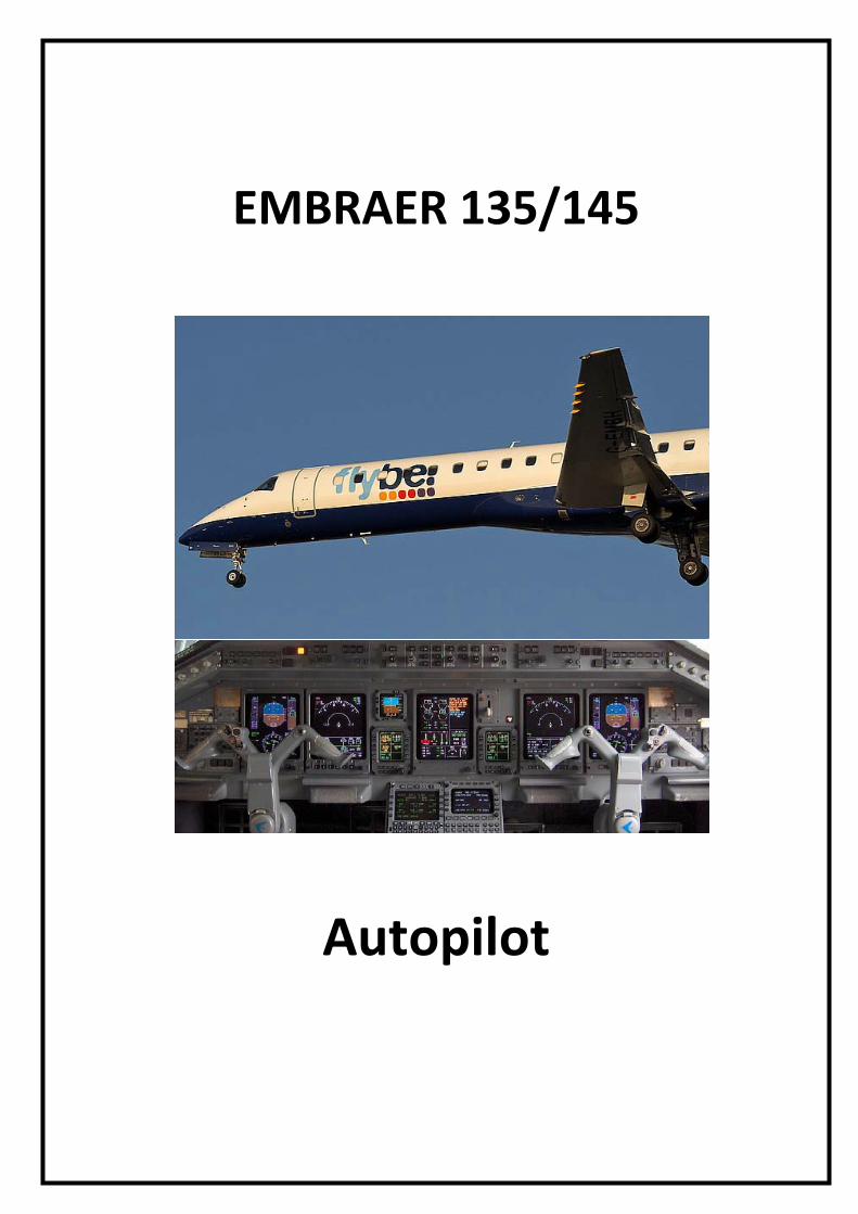
EMBRAER 135/145
Autopilot
GENERALThe Primus 1000 (P-1000) Automatic Flight Control System (AFCS) isa fully integrated, fail passive three-axis flight control system whichincorporates lateral and vertical guidance, yaw damper and automaticpitch trim functions.
Embraer 135/145 - Systems Summary [Autopilot]
Page 1
AUTOMATIC FLIGHT CONTROL SYSTEMThe Automatic Flight Control System (AFCS) consists of dual IC-600s,autopilot servos, a flight guidance controller (GC-550), a pitch and turncontroller (PC-400) and a display controller (DC-550), as follows:
− IC-600 computer - The primary component of the Automatic FlightControl System (AFCS). Controls the symbol generator, monitors,flight director and autopilot. Only the IC-600 #1 incorporates theautopilot functions.
− FLIGHT GUIDANCE CONTROLLER (GC-550) - Consists of a panelthat allows control of both Flight Director systems and autopilotfunctions. The GC-550 provides means for engaging the autopilotand the yaw damper, selecting the flight director modes and the flightdirector coupling. The Flight Guidance Controller also provides themeans for the remote selection of course, heading, vertical speedtarget, indicated airspeed target, Mach targets and preselectedaltitude.
− PITCH AND TURN CONTROLLER (PC-400) - Consists of a panelwith a Turn Control Knob and a Pitch Control Wheel. These controlsallow the pilot to manually maneuver the airplane with the autopilotengaged.
− DISPLAY CONTROLLER PANEL (DC-550) - The DC is used toselect various features on the PFD. These include HorizontalSituation Indicator (HSI) formats, navigation sources, weather displayand bearing pointer selection.
The Automatic Flight Control System interfaces with the followingsystems:
− ATTITUDE AND HEADING REFERENCE SYSTEM (AHRS):provides pitch, roll and acceleration information to the autopilotsystem via IC-600-1.
− INERTIAL REFERENCE SYSTEM (IRS): provides pitch, roll andacceleration information to the autopilot system via IC-600-1.
− RADIO MANAGEMENT SYSTEM: provides navigation data to theIC-600, including short range navigation data, VOR bearings, ILSapproach data, marker beacon tone detection and transmission,DME features and ADF.
Embraer 135/145 - Systems Summary [Autopilot]
Page 2
− AIR DATA COMPUTERS (ADCs): supply pressure altitude,barometrically corrected altitude, true airspeed, calibrated airspeed,vertical speed, Mach number, static air temperature and total airtemperature to both IC-600.
− RADIO ALTIMETER SYSTEM: provides radio altitude, low altitudeawareness and decision height information on the PFD.
− STALL PROTECTION SYSTEM: provides sensitive, visual and auralindications of an impending stall. If a stall condition is near to occur,the system actuates the stick shaker, disengages the autopilot and, ifnecessary, actuates the stick pusher.
− ENHANCED GROUND PROXIMITY WARNING SYSTEM(EGPWS/GPWS): receives, from IC-600-1, the glideslope deviation,localizer deviation, selected decision height, selected course, packeddiscrete and selected terrain range.
− ELECTRONIC FLIGHT INSTRUMENT SYSTEM (EFIS): presentinformation to the flight crew. Consists of two Primary Flight Displays(PFD), two multi function displays (MFD) and one EICAS display.
− HORIZONTAL STABILIZER CONTROL UNIT (HSCU): provides, toboth IC-600 #1 and #2, the horizontal stabilizer position. It alsoreceives, from IC-600 #1, the autopilot command, when the autopilotis engaged, and the amount of trim demanded.
− AURAL WARNING UNIT (AWU): receives signal from the autopilot,generates the appropriate messages and tones and send the audiosignal to the Audio Digital System, which routes the messages to thespeakers.
− FLAP ELECTRONIC CONTROL UNIT (FECU): moves the inboardand outboard flap panels and sends flap position signal to theautopilot system.
− FLIGHT MANAGEMENT SYSTEM (FMS): provides high accuracy inlong range lateral navigation.
Embraer 135/145 - Systems Summary [Autopilot]
Page 3
FLIGHT GUIDANCE SYSTEM
The Flight Guidance System may perform three separate functions:the Flight Director, Autopilot and Autopilot Monitoring.
FLIGHT DIRECTORThe Flight Director function provides pitch and roll attitude commandsbased on data from a variety of sensors, including attitude, heading, airdata, radio altimeter, navigation and pilot inputs. These attitudecommands are sent to the PFD for pilot display, to the autopilot forautomatic airplane control and to the autopilot monitors.
AUTOPILOTThe autopilot provides yaw stabilization and follows pitch and rollattitude commands from the flight director.The autopilot/yaw damper monitors continuously check autopilotfunctions and operation. In case of failure, they are capable ofdisengaging the autopilot and yaw damper, independent of theautopilot processor hardware.
Embraer 135/145 - Systems Summary [Autopilot]
Page 4
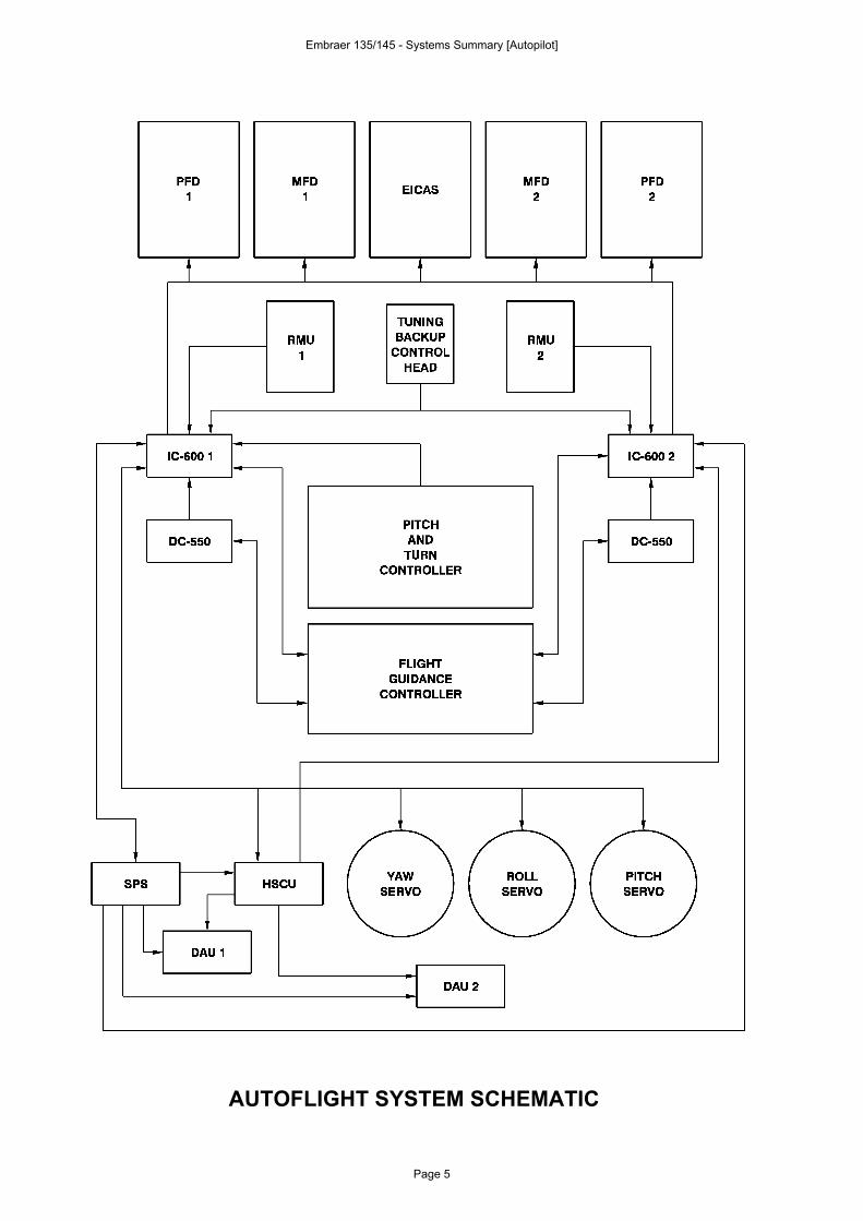
AUTOFLIGHT SYSTEM SCHEMATIC
Embraer 135/145 - Systems Summary [Autopilot]
Page 5
Ludo
Tampon
FLIGHT DIRECTOR MODESFlight Director mode selection is accomplished through the FlightGuidance Controller. Each mode selector button is illuminated for thearmed and captured mode. Also, each active mode is annunciated onthe PFD display and this annunciation makes the distinction betweenarmed and captured modes. The various modes may be divided intotwo categories: Lateral and Vertical modes.
LATERAL MODESLateral modes are those modes related to heading or roll control. Theynormally provide commands based on navigation sources.
HEADING HOLD MODE
Heading Hold mode is the default Flight Director mode when no otherlateral mode is selected. The Heading Hold mode provides rollcommands to maintain the heading at the moment of modeengagement. Once this mode is selected, the heading reference isestablished one second after the system detects a bank angle of lessthan 6º. A bank angle command of zero degrees is used (wings level)until the heading reference is established.The ROL green label is displayed on the PFD to indicate the mode isengaged. Only the pilot’s side primary heading is used by this mode. Ifthis data is invalid, the Wings Level submode is used.The Heading Hold mode is divided into Roll Hold submode, Turn Knobsubmode and Wings Level submode.
ROLL HOLD SUBMODE
The Roll Hold submode is entered from Heading Hold mode, with theautopilot engaged, by using the Touch Control Steering Button (TCS)to manually fly the airplane to a bank angle greater than 6°. Thesystem maintains the bank angle at the time the TCS button isreleased. Roll Hold submode may be canceled by either manuallyflying the airplane to less than 6° with the TCS button, by moving theTurn Control Knob out of detent or by selecting another lateral mode.This mode is annunciated on the PFD by the ROL green label.
Embraer 135/145 - Systems Summary [Autopilot]
Page 6
TURN KNOB SUBMODE
The Turn Knob submode allows the pilot to generate a roll attitudecommand manually with the Turn Control Knob. Moving the TurnControl Knob out of detent, with the autopilot engaged, cancels allother lateral modes including Heading Hold mode in both FlightDirectors.When the Turn Control Knob is out of detent, the autopilot will maintaina roll attitude proportional to the displacement of the knob. Theautopilot will revert back to Heading Hold mode when the turn knob isplaced in the detent position. Turn Knob submode is annunciated onthe PFD by the ROL green label when out of detent and the autopilot isengaged. When the autopilot is disengaged and the Turn Control Knobis out of detent, the TKNB label is displayed in the PFD and theautopilot engagement is inhibited.
WINGS LEVEL SUBMODE (Airplanes equipped with EICAS 16 andon)
The Wings Level submode provides a roll command of 0º. This modeis active in the Go Around mode, Windshear mode or if the primaryheading data is invalid. Therefore, this mode is available even if eitherattitude source is invalid. This mode is annunciated on the PFD by theROL green label.
HEADING SELECT MODE (HDG)
The HDG mode is selected by pressing the HDG button on the flightguidance controller or by arming LOC, VOR, VAPP, or BC. This modeallows the Flight Director to track the EHSI heading bug, as set by theheading select knob. The Heading Select mode is annunciated on thePFD by the green HDG label.The mode will be inhibited by the following conditions:− Turn Control Knob out of detent with autopilot engaged.− Displayed heading invalid.
The mode will be canceled if any of the following conditions occur:− Pressing the HDG button.− Changing the displayed heading source on the PFD.− LOC & BC mode capture.− VOR & VAPP capture.− Pressing the Go Around button.
Embraer 135/145 - Systems Summary [Autopilot]
Page 7
LOW BANK MODE
The Low Bank mode allows the pilot to select reduced bank angle forthe HDG mode. Bank angle limit will be reduced from 27° to 14°whenever this mode is active. The mode is selected by pressing theBNK button in the Flight Guidance Controller. This mode isannunciated only while the Heading Select mode is active, but remainsselected if Heading Select mode is deactivated, being reactivated andannunciated if Heading mode is selected again. The Low Bank mode isautomatically selected when climbing above 25000 ft and automaticallycanceled when descending below 24750 ft.
VOR NAV MODE (VOR)
The VOR NAV mode allows automatic capture and tracking of bothinbound and outbound VOR radials. The VOR mode is selected bypressing the NAV button in the Flight Guidance Controller, with VORselected on the PFD. Upon selection of VOR NAV mode, the HDGselect mode will automatically be engaged. This triggers the greenHDG annunciation on the PFD in conjunction with an armed white VORNAV annunciation, also on the PFD.At the proper time, based on course error and beam deviation, thecapture of VOR mode will cancel the HDG selected mode.The mode will be canceled or inhibited if any of the following conditionsoccur:− Pressing the NAV button.− Selecting VAPP or HDG modes.− Changing the displayed NAV source on the PFD.− Changing the displayed heading source on the PFD.− When the displayed heading is invalid.− When the displayed NAV source is invalid for more than 5 seconds.− Pressing the Go Around Button.− Turn Control Knob out of detent with autopilot engaged.
Embraer 135/145 - Systems Summary [Autopilot]
Page 8
VOR APPROACH MODE (VAPP)
The VOR Approach mode provides the same capabilities as the VORNAV mode, with higher gain for operation close to the station.It is recommended to select VAPP mode only on the final approachsegment. Therefore, the outbound segment should be flown usingsome other mode.This mode is selected by pressing the APR button on the FlightGuidance Controller, with VOR displayed on the PFD. This mode iscanceled or inhibited by the same conditions as the VOR NAV mode.Selecting VOR Approach mode, the HDG select mode willautomatically be engaged providing the green HDG annunciation onthe PFD in conjunction with the armed VOR approach and white NAVannunciation, also on the PFD.
LOCALIZER MODES (LOC/BC)
The Localizer Modes allow automatic capture and tracking of localizertransmitters. Both front course (LOC) and back course (BC)approaches are supported.The back course approach operates similar to the front courseapproach, except that the beam deviation is inverted, allowing thesystem to approach the runway 180° from the front-course.Select the Localizer mode by pressing the NAV or APR buttons on theflight guidance controller with ILS as the selected navigation source. Inthis case, the HDG select mode is automatically selected and thelocalizer is armed. On an ILS approach, when the localizer is armedand the APR button is pressed, the Glide Slope is also armed.The localizer mode captures are based on course error and beamdeviation. At the point of capture, the current armed mode (LOC or BC)is selected and locked, while HDG select mode is canceled. The LOCmode capture or BC mode capture is annunciated on the PFD by agreen LOC or green BC label, respectively.After captured, the mode will be canceled or inhibited if any of thefollowing conditions occur:− Pressing the NAV or APR buttons.− Selecting HDG mode.− Changing the displayed NAV source on the PFD.− Changing the displayed heading source on the PFD.− When the displayed heading is invalid.
Embraer 135/145 - Systems Summary [Autopilot]
Page 9
− When the displayed NAV source is invalid for more than 5 seconds.− When the displayed Glide Slope deviation is invalid for more than 5
seconds, with GS mode captured.− When the on-side attitude is invalid.− When the selected air data source is invalid.− Pressing Go Around button.− Turn Control Knob out of detent with autopilot engaged.
LNAV MODE
The LNAV mode allows the Flight Director to capture and track the rollsteering signal from the long range navigation system (FMS/GPS).With FMS selected on the PFD, select LNAV mode by pressing theNAV button on the Flight Guidance Controller. This mode willautomatically engage HDG select mode, triggering a green HDGannunciation on the PFD in conjunction with a white LNAVannunciation, also on the PFD.The mode will be canceled or inhibited if any of the following conditionsoccur:− Pressing the NAV button.− Selecting HDG mode.− Changing the displayed NAV source on the PFD.− Changing the displayed heading source on the PFD.− When the displayed heading is invalid.− When the lateral steering command is invalid.− Pressing the Go Around button.− Turn Control Knob out of detent with autopilot engaged.
Embraer 135/145 - Systems Summary [Autopilot]
Page 10
VERTICAL MODESVertical modes are those modes related to pitch control. Due to thenecessity of maintaining the wings leveled during Go Around, thisvertical maneuver may also be considered as a lateral mode.
PITCH HOLD MODE
The Pitch Hold mode is the default mode that controls the airplanewhen no other Flight Director mode is selected.The Pitch Hold mode is synchronized to the existing pitch attitude andprovides an error signal to the command bars and autopilot function.By pressing the Touch Control Steering Button (TCS), the pilot maymanually change the pitch attitude and then allow the system toresynchronize to the new attitude when the button is released.Should the autopilot be engaged and the Flight Director is in the pitchhold mode, pitch attitude reference can be changed by rotating thepitch control wheel on the pitch and turn controller.The pitch control wheel allows continuous variable rates andamplitudes of the pitch reference. A PIT label is displayed on the PFDto indicate mode engaged.
ALTITUDE HOLD MODE (ALT)
The Altitude Hold mode generates an altitude error signal from areference altitude and provides a pitch command, which allows theautopilot to maintain altitude.The Altitude Hold mode is selected by pressing the ALT button on theFlight Guidance Controller or can also be activated automatically by thealtitude preselect mode. This mode is annunciated on the PFD by theALT label.The mode will be canceled or inhibited if any of the following conditionsoccur:− Pressing the ALT button.− Selecting VS, FLC, or SPD modes.− Glide slope capture.− When the air data is invalid.− Pressing the Go Around Button.− Pitch control wheel moved with autopilot engaged.
Embraer 135/145 - Systems Summary [Autopilot]
Page 11
ALTITUDE PRESELECT MODE (ASEL)
The Altitude Preselect mode provides means for the system to climb ordescend to a predetermined altitude and then level off and maintainthe preselected altitude.Preselected altitude is set through the ASEL knob on the FlightGuidance Controller and is displayed on the top right corner of thePFD. This mode is annunciated by the white ASEL label on the PFD.Pitch Hold, Speed Hold or Vertical Speed Hold must be used to climbor descend towards the preselected altitude or Flight Level Change(FLC).The ASEL mode will arm automatically if the airplane climbs ordescends towards a preselected altitude. The ASEL mode willautomatically capture and cancel any existing mode at the appropriatepoint based on preselected altitude error and vertical speed. Thesystem will automatically switch to altitude hold mode after the airplanehas leveled off at the selected altitude.The mode will be canceled and/or inhibited if any of the followingconditions occur:− Changing the preselected altitude.− Selecting ALT, VS, FLC, or SPD modes.− Glide slope capture.− When the air data is invalid.− Pressing the Go Around Button.
FLIGHT LEVEL CHANGE MODE (FLC)
The Flight Level Change mode (FLC) provides means of climbing ordescending to a preselected altitude at a pre-programmed schedule.When the preselected altitude is above the current altitude and theflight level change mode is selected, the Flight Director provides aspeed command at the predetermined climb speed schedule. Whenthe preselected altitude is below the current altitude and FLC isselected, the FD provides a command to descend at a determined rateof descent. The PFD will display the current IAS, Mach or verticalspeed bug as appropriate and the target speed can be adjusted onlyby deselecting the flight level change mode.As the airplane approaches the preselected altitude, the Flight Directorwill cycle among ASEL ARM, ASEL CAP, and ALT HOLD to capturethe preselected altitude.
Embraer 135/145 - Systems Summary [Autopilot]
Page 12
The following protections are provided with this mode:− Maximum normal and longitudinal acceleration: 0.1 G.− Maximum airspeed: VMO or MMO.− System will maintain the preselected altitude.
The Flight Level Change mode may be activated by selecting analtitude and pressing the FLC button in the Flight Guidance Controller.This mode is annunciated on the PFD by the CLB label, when followingthe IAS/MACH climb profile, or by the DES label when following avertical descent profile of - 2000 ft/min.The mode will be canceled or inhibited if any of the following conditionsoccur:− Pressing the FLC button.− Changing the preselected altitude.− Selecting ALT, VS, FLC, or SPD modes.− Glide slope capture.− When the air data is invalid.− Pressing the Go Around Button.
DESCENT RATE SCHEDULE:
For EICAS versions up to 13:
The descent rate schedule is -2000 ft/min.
For EICAS versions 14 and on:
From 37000 ft to 12000 ft, the descent rate schedule is −2000ft/min.From 12000 ft to 10000 ft the descent rate schedule is −2000 ft/minto −1000 ft/min.From 10000 ft and below the descent rate schedule is −1000 ft/min.
Embraer 135/145 - Systems Summary [Autopilot]
Page 13
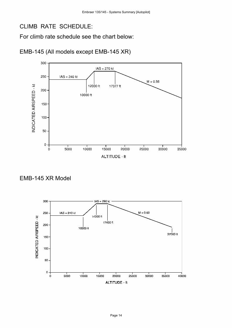
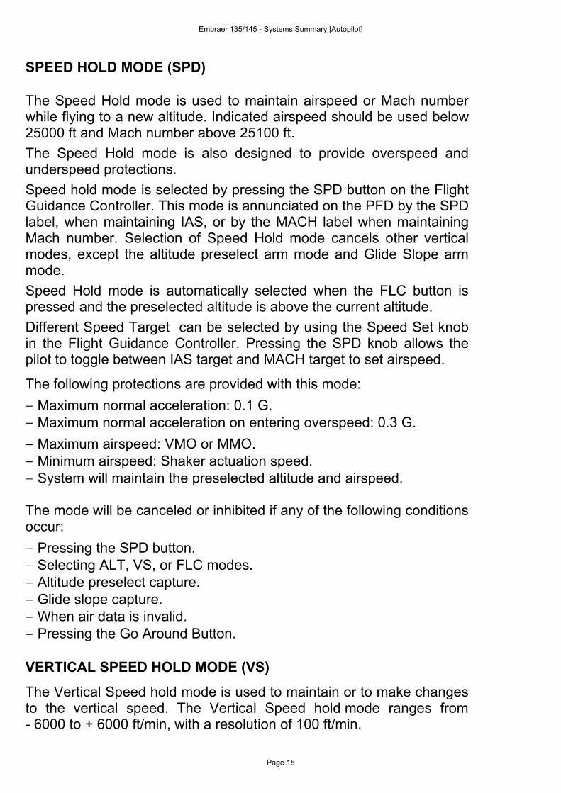
CLIMB RATE SCHEDULE:
For climb rate schedule see the chart below:
EMB-145 (All models except EMB-145 XR)
EMB-145 XR Model
Embraer 135/145 - Systems Summary [Autopilot]
Page 14
Ludo
Tampon
Ludo
Tampon
SPEED HOLD MODE (SPD)
The Speed Hold mode is used to maintain airspeed or Mach numberwhile flying to a new altitude. Indicated airspeed should be used below25000 ft and Mach number above 25100 ft.The Speed Hold mode is also designed to provide overspeed andunderspeed protections.Speed hold mode is selected by pressing the SPD button on the FlightGuidance Controller. This mode is annunciated on the PFD by the SPDlabel, when maintaining IAS, or by the MACH label when maintainingMach number. Selection of Speed Hold mode cancels other verticalmodes, except the altitude preselect arm mode and Glide Slope armmode.Speed Hold mode is automatically selected when the FLC button ispressed and the preselected altitude is above the current altitude.Different Speed Target can be selected by using the Speed Set knobin the Flight Guidance Controller. Pressing the SPD knob allows thepilot to toggle between IAS target and MACH target to set airspeed.
The following protections are provided with this mode:− Maximum normal acceleration: 0.1 G.− Maximum normal acceleration on entering overspeed: 0.3 G.− Maximum airspeed: VMO or MMO.− Minimum airspeed: Shaker actuation speed.− System will maintain the preselected altitude and airspeed.
The mode will be canceled or inhibited if any of the following conditionsoccur:− Pressing the SPD button.− Selecting ALT, VS, or FLC modes.− Altitude preselect capture.− Glide slope capture.− When air data is invalid.− Pressing the Go Around Button.
VERTICAL SPEED HOLD MODE (VS)
The Vertical Speed hold mode is used to maintain or to make changesto the vertical speed. The Vertical Speed hold mode ranges from- 6000 to + 6000 ft/min, with a resolution of 100 ft/min.
Embraer 135/145 - Systems Summary [Autopilot]
Page 15
The Vertical Speed Hold mode is selected by pressing the VS buttonon the Flight Guidance Controller or automatically, when FLC button ispressed and the preselected altitude is below the current altitude. Thismode is annunciated on the PFD by the VS label.Selection of this mode cancels other vertical modes, except the altitudepreselect arm and Glide Slope arm.Vertical speed may be changed by using the Speed Set knob, on theflight guidance controller.The following protections are provided with this mode:− Maximum airspeed: VMO.− Minimum airspeed: Shaker actuation speed.
The mode will be canceled or inhibited if any of the following conditionsoccur:− Pressing the VS button.− Selecting ALT, SPD, or FLC modes.− Altitude preselect capture.− Glide slope capture.− When air data is invalid.− Pressing the Go Around Button.
GLIDE SLOPE MODE (GS)
The Glide Slope mode allows automatic capture and tracking to GlideSlope transmitters. Select Glide Slope mode by pressing the APRbutton with ILS as a navigation source.Selecting Glide Slope mode automatically arms GS (in conjuction withLOC). The PFD will display a white localizer LOC and a white GlideSlope GS annunciation. The localizer mode capture will occur with agreen LOC annunciation on the PFD. The Glide Slope mode capture,with a green GS annunciation on the PFD, will occur only afterLocalizer mode has been captured.After captured, the GS mode will be canceled or inhibited if any of thefollowing conditions occur:− Pressing the APR or NAV buttons.− Lost Localizer mode.− Selecting ALT, SPD, VS, or FLC modes . − Glide slope deviation invalid for a period greater than 5 seconds.− Pressing the Go Around Button.
Embraer 135/145 - Systems Summary [Autopilot]
Page 16
GO AROUND MODE
TAKEOFF SUBMODE
The Takeoff submode provides a wings level command and a fixedpitch up attitude command of 14° (for flaps at 9°), 13° (for flaps at 18°)or 12° (for flaps at 22°), which are indicated by the Flight Directorcommand bars on the EADI.This mode is selected by pressing any of the Go Around buttons on thethrust levers and annunciated by the ROL label and TO label, both onthe PFD.The Takeoff submode will be canceled if any of the following conditionsoccur:− Pushing the TCS button.− Selecting ALT, SPD, VS, or FLC mode.− Transition to capture Altitude Preselect mode.− Air data computer source selection is changed.The Takeoff submode is available on the ground with airspeed below60 KIAS or in flight within 400 ft above the runway.The Go Around mode, as well as the Vertical Speed Control knob, willbe inhibited while Takeoff submode is engaged.After reaching the 400 ft delta, pressing the Go Around button willengage the Go Around mode. Once the 400 ft boundary is crossed, the400 ft delta requirement will be ignored, to avoid restricting any GAmaneuvers later in the flight.If the autopilot is selected with the Takeoff submode engaged, thissubmode will drop into Pitch Hold mode and synchronize to the currentattitude. The Takeoff submode will not be coupled to the autopilot,which may be used after climbing above the airplane MinimumEngagement Height (MEH).When the autopilot is not engaged, wings level will be the active lateralmode and the ROL label will be displayed on the PFD.A Pitch Limit Indicator (PLI) is displayed on the EADI sphere when themargin prior to the stick shaker set point is below or equal to 10°. In thecase of an invalid Stall Protection Computer signal, the PLI will bebiased out of view and an amber AOA annunciation will be displayedon the PFD.
Embraer 135/145 - Systems Summary [Autopilot]
Page 17
GO AROUND SUBMODE
The Go Around Submode should be selected once the decision todiscontinue the approach has been taken. Although commanding anose up attitude, the need to maintain wings leveled causes this modeto incorporate both lateral and vertical modes features.
- Speed Target Submode:
The Speed Target submode will command airplane pitch in orderto allow a climbing turn at an airspeed of around 1.23 VS. Once apositive rate of climb has been achieved, the Speed Targetsubmode will limit the pitch angle at 10° nose up. The systemmanages airspeed, altitude and comfort. Therefore, accelerationsare limited to avoid passenger discomfort, while maintaining targetairspeed. If the airspeed can not be maintained, altitude will beheld.The Speed Target mode will initially command the Flight DirectorCommand Bar and the autopilot pitch up attitude to 10° nose upfor at least 20 seconds. After this, the Flight Director provides apitch up command based on the IAS Speed Hold mode followingthe go-around speed preselected on the airspeed bug and limitedwithin 1.23 VS and 170 KIAS.
NOTE: The Flight Director will revert automatically to IAS speedhold, without waiting 20 seconds if at the time the GoAround button is pressed or during the time the GoAround mode is engaged, the airplane is below 1.23 VS.
The airspeed bug is displayed on the airspeed tape on the PFDand a pitch limit indicator is displayed on the EADI. If the StallProtection Computer signal becomes invalid, the PLI is removed.The mode may be engaged by pressing any of the Go Aroundbuttons on the thrust levers. The submode may be engaged onlyat radio altitudes below 2500 ft, or below 15000 ft pressurealtitude for an invalid Radio Altimeter signal. This feature isprovided to protect against inadvertent Go Around selectionsduring cruise.The autopilot may be coupled to the Speed Target submodeabove the airplane’s Minimum Use Height (MUH). However, thecrew will not be alerted in case of coupling this submode belowthe MUH.
Embraer 135/145 - Systems Summary [Autopilot]
Page 18
The GA label is annunciated on the PFD during the first 20seconds, when the 10° pitch up command exists. When the IASpreselected speed bug is used on the go-around, the GA labelswitches to the IAS label and the system provides the pitchcommand based on the IAS Hold mode.The Speed Target submode will disengage on selection of a newvertical mode. The submode will ignore a preselected altitudebelow the airplane and will not fly away from a preselected altitudeabove the airplane. Altitude Preselect mode will be inhibited if thepreselect altitude is less than Speed Target submodeengagement altitude plus 400 ft (pressure altitude). This feature isprovided to avoid the airplane leveling off if the pilot has notreadjusted the preselected altitude to the new missed approachaltitude.The Speed knob will be inhibited while GA mode is engaged.When the autopilot is not engaged, wings level will be the activelateral mode and the ROL label will be displayed on the PFD. Ifthe autopilot is engaged, the lateral mode will remain wings leveland will also be displayed as ROL on the PFD.
WINDSHEAR ESCAPE GUIDANCE MODE
The Windshear Escape Guidance mode is provided in order to recoverfrom a windshear situation.
Embraer 135/145 - Systems Summary [Autopilot]
Page 19
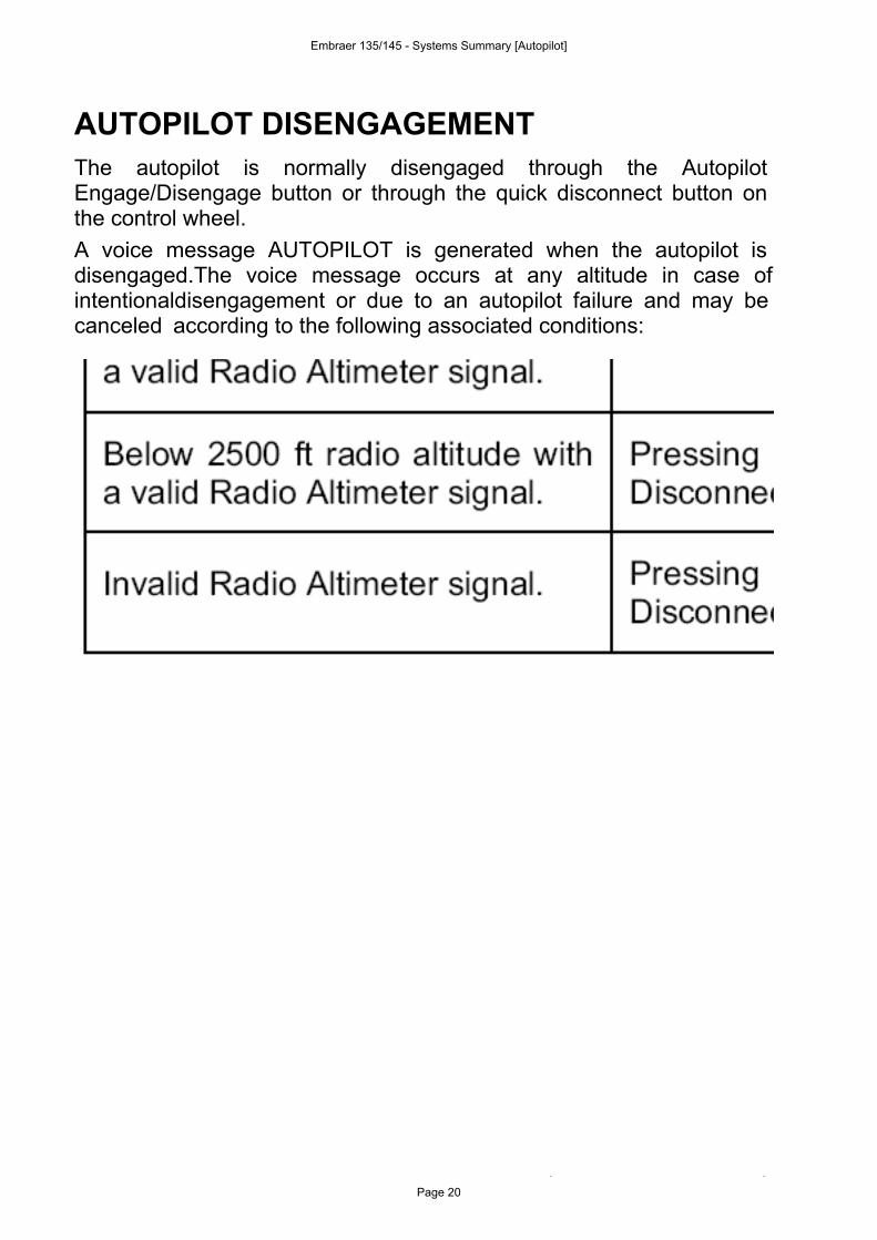
AUTOPILOT DISENGAGEMENTThe autopilot is normally disengaged through the AutopilotEngage/Disengage button or through the quick disconnect button onthe control wheel.A voice message AUTOPILOT is generated when the autopilot isdisengaged.The voice message occurs at any altitude in case of intentionaldisengagement or due to an autopilot failure and may be canceled according to the following associated conditions:
Embraer 135/145 - Systems Summary [Autopilot]
Page 20
Ludo
Tampon
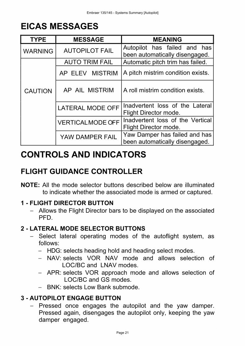
EICAS MESSAGESTYPE MESSAGE MEANING
WARNING AUTOPILOT FAIL Autopilot has failed and hasbeen automatically disengaged.
AUTO TRIM FAIL Automatic pitch trim has failed.
AP ELEV MISTRIM A pitch mistrim condition exists.
CAUTION AP AIL MISTRIM A roll mistrim condition exists.
LATERAL MODE OFF Inadvertent loss of the LateralFlight Director mode.
VERTICALMODE OFF Inadvertent loss of the VerticalFlight Director mode.
YAW DAMPER FAIL Yaw Damper has failed and hasbeen automatically disengaged.
CONTROLS AND INDICATORS
FLIGHT GUIDANCE CONTROLLER
NOTE: All the mode selector buttons described below are illuminatedto indicate whether the associated mode is armed or captured.
1 - FLIGHT DIRECTOR BUTTON− Allows the Flight Director bars to be displayed on the associated
PFD.
2 - LATERAL MODE SELECTOR BUTTONS− Select lateral operating modes of the autoflight system, as
follows:− HDG: selects heading hold and heading select modes.− NAV: selects VOR NAV mode and allows selection of
LOC/BC and LNAV modes.− APR: selects VOR approach mode and allows selection of
LOC/BC and GS modes.− BNK: selects Low Bank submode.
3 - AUTOPILOT ENGAGE BUTTON− Pressed once engages the autopilot and the yaw damper.
Pressed again, disengages the autopilot only, keeping the yawdamper engaged.
Embraer 135/145 - Systems Summary [Autopilot]
Page 21
4 - VERTICAL MODE SELECTOR BUTTONS− Select vertical operating modes of the autoflight system, as
follows:− SPD: selects Speed Hold mode.− FLC: selects Flight Level Change mode.− VS: selects Vertical Speed hold mode.− ALT: selects Altitude Hold mode.
5 - ALTITUDE PRESELECT KNOB− Allows preselection of altitude in 100 ft increments.
6 - COURSE SELECTOR KNOB− Allows selection of course in 1° increments.− Pressing the knob synchronizes the selected course to the VOR
bearing.
7 - VERTICAL SPEED CONTROL KNOB AND IAS/M SELECTORBUTTON− Pressing the knob toggles between the speed modes MACH
and IAS.− When in SPD mode, rotation of this knob allows selection of
indicated airspeed in one-knot increments or Mach Number in0.01 increments.
− When in VS mode, rotation of this knob allows selection ofvertical speed in 100 ft/min increments.
8 - YAW DAMPER ENGAGE BUTTON− Pressed once, engages only the Yaw Damper. Pressed again
disengages the yaw damper and the autopilot, if it is engaged.
9 - AUTOPILOT COUPLE BUTTON− Allows the pilot’s or copilot’s Flight Director commands to control
the autopilot. The couple button can be pressed with theautopilot engaged or disengaged. However, if the Flight Directoris switched, the modes will drop out and the autopilot will remainengaged (if already engaged) and revert to basic autopilot mode(pitch and roll).
10- HEADING SELECT KNOB− Allows selection of heading in 1° increments.− Pressing this knob synchronizes the heading selection to the
current displayed heading.
Embraer 135/145 - Systems Summary [Autopilot]
Page 22
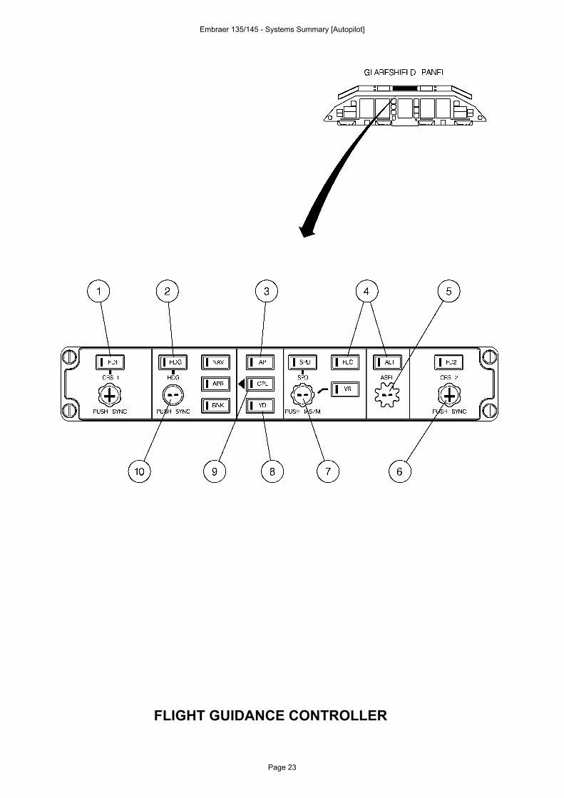
FLIGHT GUIDANCE CONTROLLER
Embraer 135/145 - Systems Summary [Autopilot]
Page 23
Ludo
Tampon
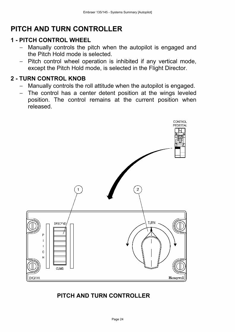
PITCH AND TURN CONTROLLER1 - PITCH CONTROL WHEEL
− Manually controls the pitch when the autopilot is engaged andthe Pitch Hold mode is selected.
− Pitch control wheel operation is inhibited if any vertical mode,except the Pitch Hold mode, is selected in the Flight Director.
2 - TURN CONTROL KNOB− Manually controls the roll attitude when the autopilot is engaged.− The control has a center detent position at the wings leveled
position. The control remains at the current position whenreleased.
PITCH AND TURN CONTROLLER
Embraer 135/145 - Systems Summary [Autopilot]
Page 24
Ludo
Tampon
CONTROL WHEEL
1 - TOUCH CONTROL STEERING BUTTON (TCS)
− Allows manual maneuvering of the airplane without disengagingthe autopilot. The airplane may be maneuvered to any desiredpitch attitude while the TCS button is pressed. When the buttonis released, the following occurs:− Primary servos reengage.− The computer synchronizes itself to the new pitch attitude
and vertical mode and maintain it.− Lateral control is returned to the previously selected lateral
mode (return to the lateral mode is filtered to prevent rapidmaneuvers).
− After glide slope capture in APR mode with the autopilotengaged, if the TCS button is pressed and released, theautopilot will resume the controls and turn the airplane to the ILScenter beam.
2 - QUICK DISCONNECT BUTTON
− Provides the means to disengage autopilot and yaw damper.− The pilot’s and copilot’s buttons are interconnected to allow
autopilot cancellation from either seat.− For Post-Mod. SB 145-22-0001 airplanes or airframes S/N
145001 through 145003, 145041 and on, if the autopilot isdisengaged and the button is pressed, the voice messageAUTOPILOT will be canceled in 2 seconds.
Embraer 135/145 - Systems Summary [Autopilot]
Page 25
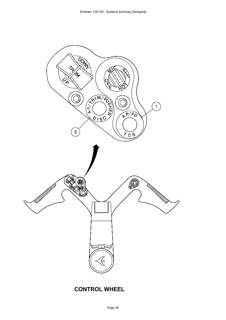
CONTROL WHEEL
Embraer 135/145 - Systems Summary [Autopilot]
Page 26
Ludo
Tampon
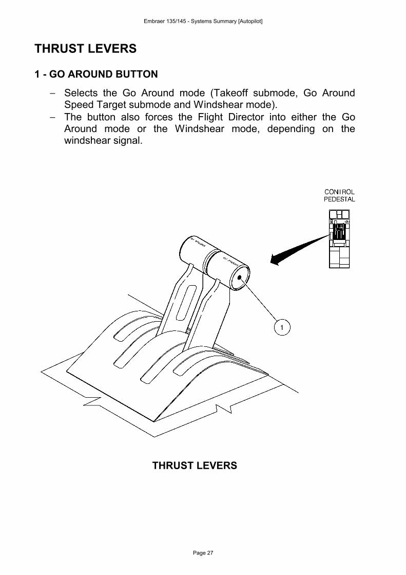
THRUST LEVERS
1 - GO AROUND BUTTON
− Selects the Go Around mode (Takeoff submode, Go AroundSpeed Target submode and Windshear mode).
− The button also forces the Flight Director into either the GoAround mode or the Windshear mode, depending on thewindshear signal.
THRUST LEVERS
Embraer 135/145 - Systems Summary [Autopilot]
Page 27
Ludo
Tampon
DISPLAY CONTROLLER (DC-550)
1 - NAVIGATION SOURCES SELECTOR BUTTON− Provides the selection of the VHF NAV (VOR, ILS and MLS) as
navigation source for the EHSI. If the VHF NAV is alreadyselected, pressing the NAV Button selects the opposite VHFNAV as navigation source for the on-side EHSI. Pressing theNAV Button once again will restore the normal operation: VHFNAV 1 information presented on the PFD 1 and VHF NAV 2information presented on the PFD 2.
2 - FMS SOURCE SELECTOR BUTTON (optional)− Provides the selection of the FMS as navigation source for the
EHSI.− On airplanes equipped with dual FMS, pressing the FMS Button
for the second time selects the opposite FMS as navigationsource for the on-side EHSI (and for the on-side MFD MAP).Pressing the FMS Button once again will restore the normaloperation: FMS 1 information presented on the PFD 1 (and MFD1) and FMS 2 information presented on the PFD 2 (and MFD 2).
3 - BEARING SELECTOR KNOBOFF: The associated PFD bearing pointers are disabled.NAV 1 (2): Selects the respective VHF NAV as source for the
associated bearing pointer.ADF: Selects the respective ADF as source for the
associated bearing pointer.FMS: Selects the FMS as source for the associated bearing
pointer.4 - DECISION HEIGHT SETTING AND IC-600 TEST KNOB
− Provides the Radio Altimeter (RA) decision height setting.− When pressed on ground provides the IC-600 and RA test
activation. Refer to Section 2-4 – Crew Awareness for furtherinformation on test function and Section 2-17 – FlightInstruments for further information on decision height settingand RA test in flight.
Embraer 135/145 - Systems Summary [Autopilot]
Page 28
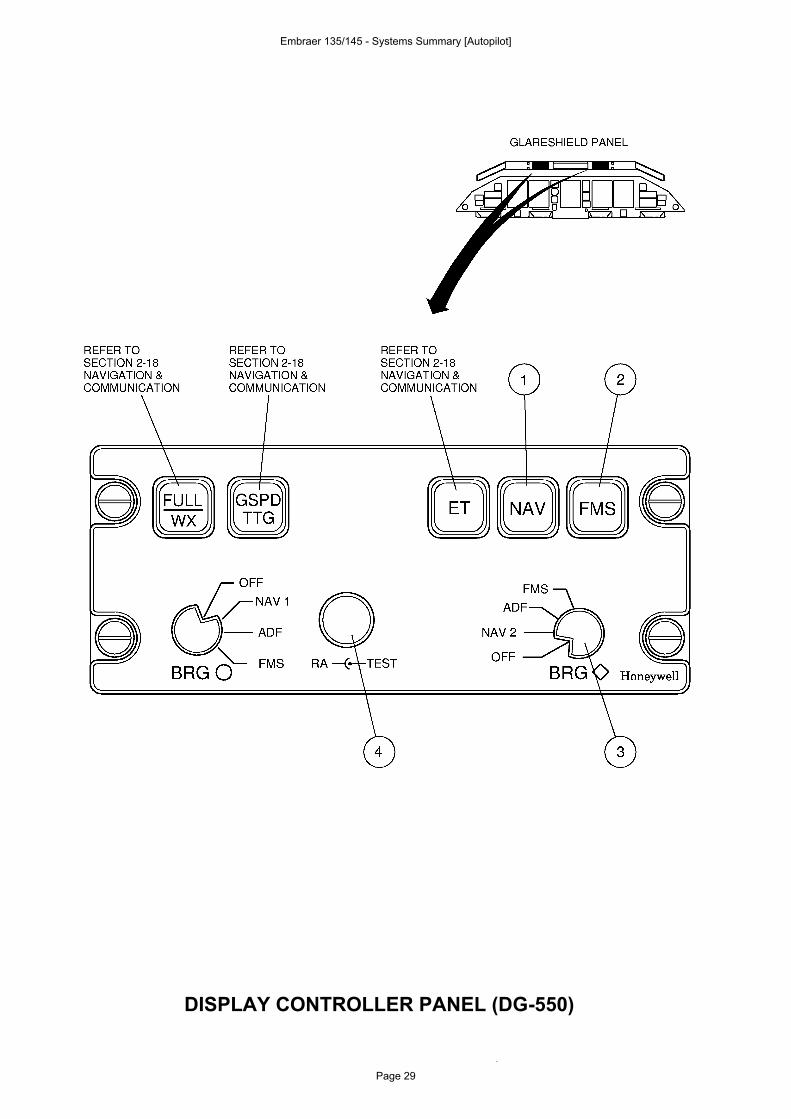
DISPLAY CONTROLLER PANEL (DG-550)
Embraer 135/145 - Systems Summary [Autopilot]
Page 29
Ludo
Tampon
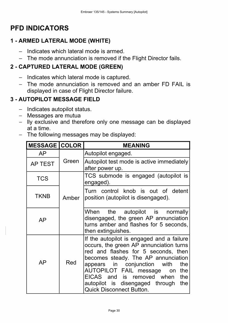
PFD INDICATORS
1 - ARMED LATERAL MODE (WHITE)
− Indicates which lateral mode is armed.− The mode annunciation is removed if the Flight Director fails.
2 - CAPTURED LATERAL MODE (GREEN)
− Indicates which lateral mode is captured.− The mode annunciation is removed and an amber FD FAIL is
displayed in case of Flight Director failure.3 - AUTOPILOT MESSAGE FIELD
− Indicates autopilot status.− Messages are mutua− lly exclusive and therefore only one message can be displayed
at a time.− The following messages may be displayed:
MESSAGE COLOR MEANINGAP Autopilot engaged.
AP TEST Green Autopilot test mode is active immediatelyafter power up.
TCS TCS submode is engaged (autopilot isengaged).
TKNB AmberTurn control knob is out of detentposition (autopilot is disengaged).
APWhen the autopilot is normallydisengaged, the green AP annunciationturns amber and flashes for 5 seconds,then extinguishes.
AP Red
If the autopilot is engaged and a failureoccurs, the green AP annunciation turnsred and flashes for 5 seconds, thenbecomes steady. The AP annunciationappears in conjunction with theAUTOPILOT FAIL message on theEICAS and is removed when theautopilot is disengaged through theQuick Disconnect Button.
Embraer 135/145 - Systems Summary [Autopilot]
Page 30
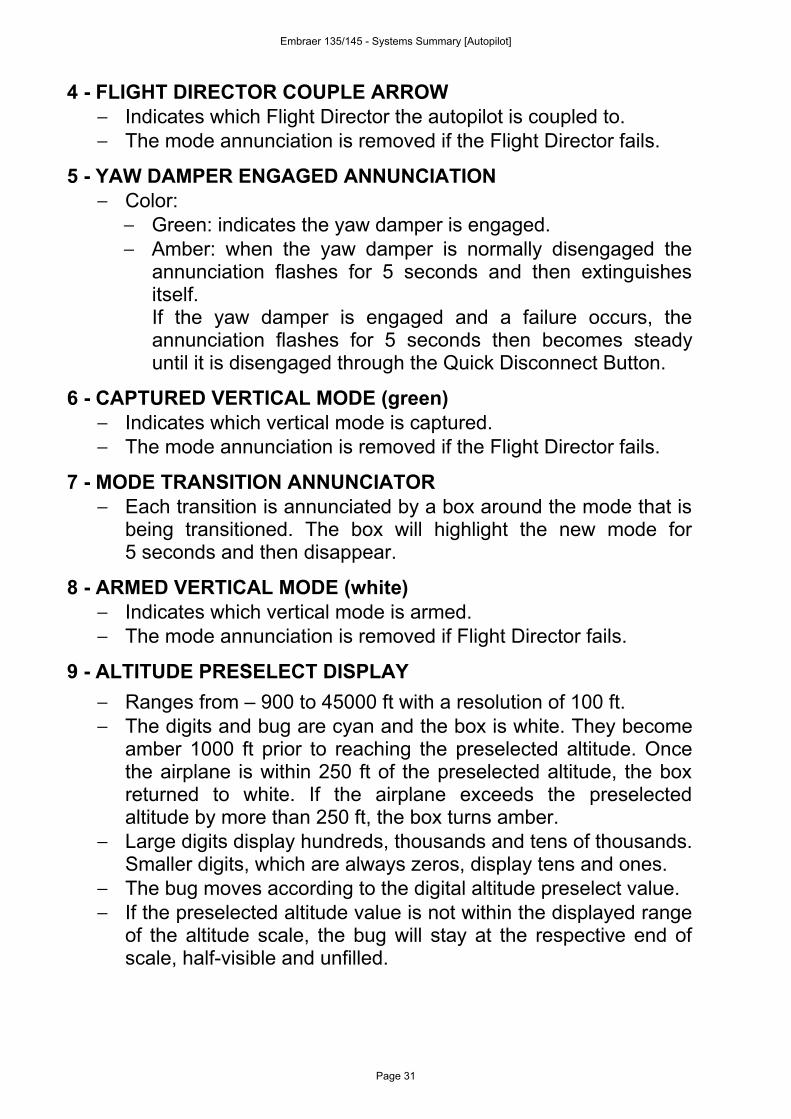
4 - FLIGHT DIRECTOR COUPLE ARROW− Indicates which Flight Director the autopilot is coupled to.− The mode annunciation is removed if the Flight Director fails.
5 - YAW DAMPER ENGAGED ANNUNCIATION− Color:
− Green: indicates the yaw damper is engaged.− Amber: when the yaw damper is normally disengaged the
annunciation flashes for 5 seconds and then extinguishesitself.If the yaw damper is engaged and a failure occurs, theannunciation flashes for 5 seconds then becomes steadyuntil it is disengaged through the Quick Disconnect Button.
6 - CAPTURED VERTICAL MODE (green)− Indicates which vertical mode is captured.− The mode annunciation is removed if the Flight Director fails.
7 - MODE TRANSITION ANNUNCIATOR− Each transition is annunciated by a box around the mode that is
being transitioned. The box will highlight the new mode for5 seconds and then disappear.
8 - ARMED VERTICAL MODE (white)− Indicates which vertical mode is armed.− The mode annunciation is removed if Flight Director fails.
9 - ALTITUDE PRESELECT DISPLAY− Ranges from – 900 to 45000 ft with a resolution of 100 ft.− The digits and bug are cyan and the box is white. They become
amber 1000 ft prior to reaching the preselected altitude. Oncethe airplane is within 250 ft of the preselected altitude, the boxreturned to white. If the airplane exceeds the preselectedaltitude by more than 250 ft, the box turns amber.
− Large digits display hundreds, thousands and tens of thousands.Smaller digits, which are always zeros, display tens and ones.
− The bug moves according to the digital altitude preselect value.− If the preselected altitude value is not within the displayed range
of the altitude scale, the bug will stay at the respective end ofscale, half-visible and unfilled.
Embraer 135/145 - Systems Summary [Autopilot]
Page 31
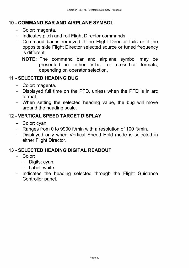
10 - COMMAND BAR AND AIRPLANE SYMBOL− Color: magenta.− Indicates pitch and roll Flight Director commands.− Command bar is removed if the Flight Director fails or if the
opposite side Flight Director selected source or tuned frequencyis different.NOTE: The command bar and airplane symbol may be
presented in either V-bar or cross-bar formats,depending on operator selection.
11 - SELECTED HEADING BUG− Color: magenta.− Displayed full time on the PFD, unless when the PFD is in arc
format.− When setting the selected heading value, the bug will move
around the heading scale.
12 - VERTICAL SPEED TARGET DISPLAY− Color: cyan.− Ranges from 0 to 9900 ft/min with a resolution of 100 ft/min.− Displayed only when Vertical Speed Hold mode is selected in
either Flight Director.
13 - SELECTED HEADING DIGITAL READOUT− Color:
− Digits: cyan.− Label: white.
− Indicates the heading selected through the Flight GuidanceController panel.
Embraer 135/145 - Systems Summary [Autopilot]
Page 32
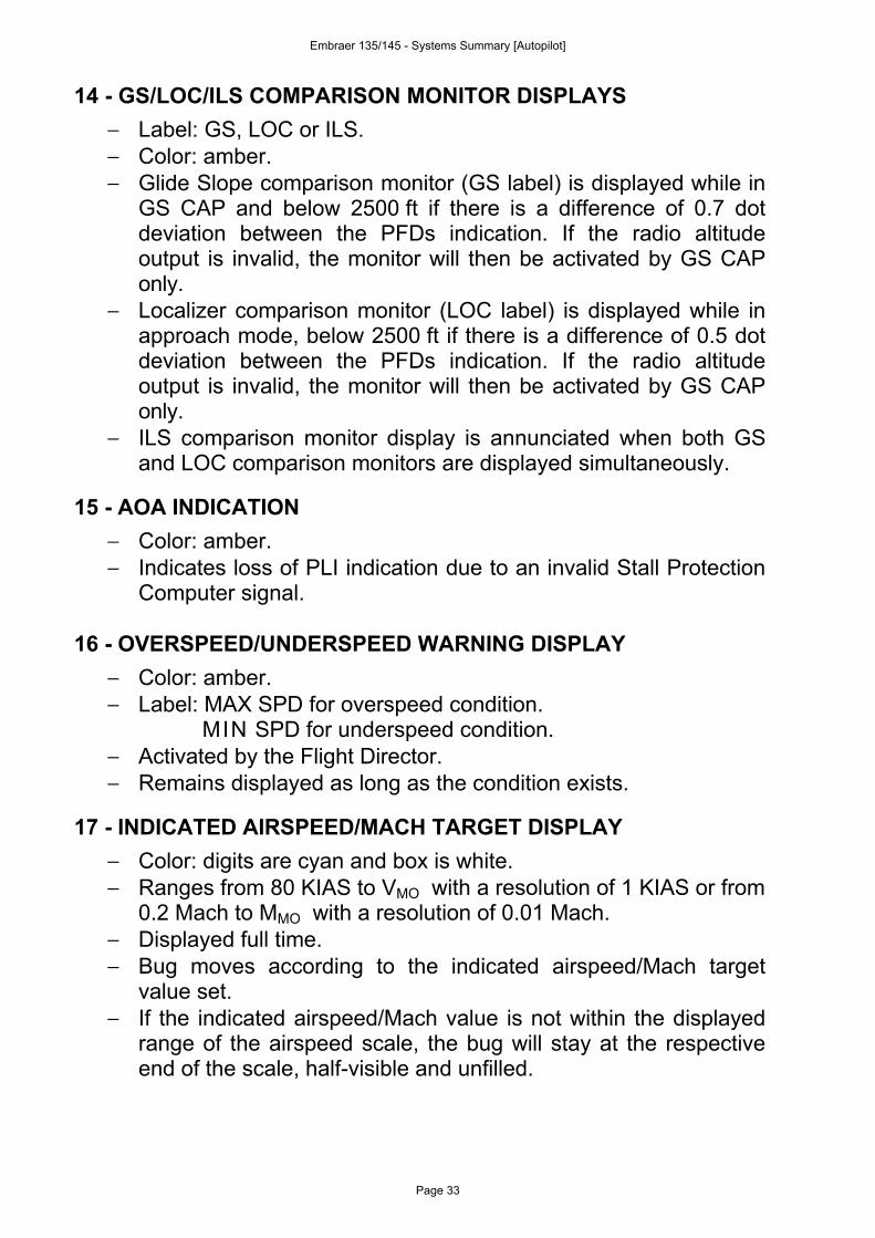
14 - GS/LOC/ILS COMPARISON MONITOR DISPLAYS− Label: GS, LOC or ILS.− Color: amber.− Glide Slope comparison monitor (GS label) is displayed while in
GS CAP and below 2500 ft if there is a difference of 0.7 dotdeviation between the PFDs indication. If the radio altitudeoutput is invalid, the monitor will then be activated by GS CAPonly.
− Localizer comparison monitor (LOC label) is displayed while inapproach mode, below 2500 ft if there is a difference of 0.5 dotdeviation between the PFDs indication. If the radio altitudeoutput is invalid, the monitor will then be activated by GS CAPonly.
− ILS comparison monitor display is annunciated when both GSand LOC comparison monitors are displayed simultaneously.
15 - AOA INDICATION− Color: amber.− Indicates loss of PLI indication due to an invalid Stall Protection
Computer signal.
16 - OVERSPEED/UNDERSPEED WARNING DISPLAY− Color: amber.− Label: MAX SPD for overspeed condition.
MIN SPD for underspeed condition.− Activated by the Flight Director.− Remains displayed as long as the condition exists.
17 - INDICATED AIRSPEED/MACH TARGET DISPLAY− Color: digits are cyan and box is white.− Ranges from 80 KIAS to VMO with a resolution of 1 KIAS or from
0.2 Mach to MMO with a resolution of 0.01 Mach.− Displayed full time.− Bug moves according to the indicated airspeed/Mach target
value set.− If the indicated airspeed/Mach value is not within the displayed
range of the airspeed scale, the bug will stay at the respectiveend of the scale, half-visible and unfilled.
Embraer 135/145 - Systems Summary [Autopilot]
Page 33
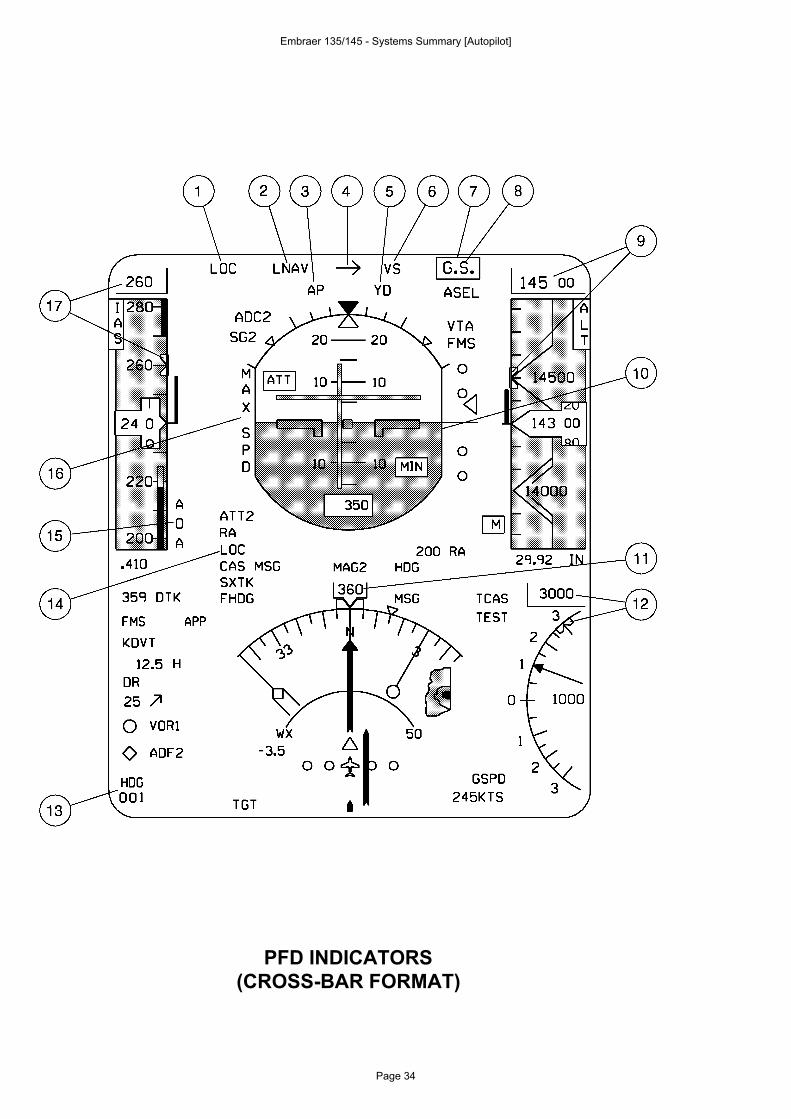
PFD INDICATORS(CROSS-BAR FORMAT)
Embraer 135/145 - Systems Summary [Autopilot]
Page 34
Ludo
Tampon
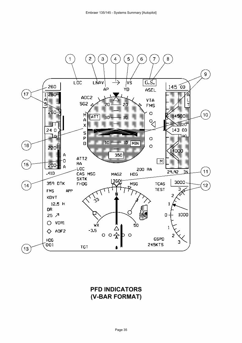
PFD INDICATORS(V-BAR FORMAT)
Embraer 135/145 - Systems Summary [Autopilot]
Page 35
Ludo
Tampon
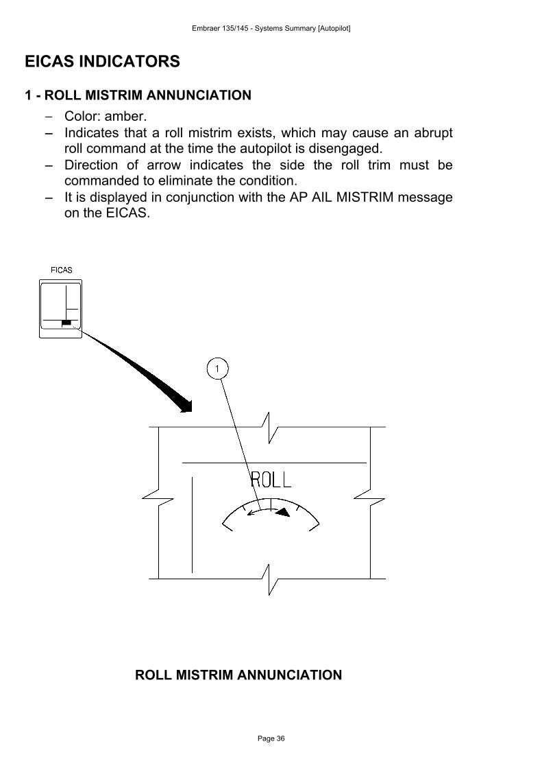
EICAS INDICATORS
1 - ROLL MISTRIM ANNUNCIATION− Color: amber.− − Indicates that a roll mistrim exists, which may cause an abrupt
roll command at the time the autopilot is disengaged.− − Direction of arrow indicates the side the roll trim must be
commanded to eliminate the condition.− − It is displayed in conjunction with the AP AIL MISTRIM message
on the EICAS.
ROLL MISTRIM ANNUNCIATION
Embraer 135/145 - Systems Summary [Autopilot]
Page 36
Ludo
Tampon
CATEGORY II APPROACH (OPTIONAL)The IC-600 may be optionally equipped with a Category II checklistlogic warning which is automatically activated whenever the DecisionHeight is selected between 80 and 200 ft through the RA knob on theDisplay Control Panel.
CATEGORY II CONDITIONSThe required conditions to obtain a Cat II valid conditions are:
− Cat II Decision Height setting on both Display Control Panels(greater than 80 ft and less than 200 ft).
− Radio altitude between 2500 and 80 ft.− Flaps 22°.− NAV 1 on pilot’s side and NAV 2 on copilot’s side, both NAV’s
tuned to the same frequency.− An active approach mode selected.− Both Flight Directors operational (command bars visible).− Attitude and heading valid on both PFDs.− Glide slope and localizer deviation valid on both PFDs.− No reversions (SG, AHRS, IRS or ADC) modes selected on
both PFDs.− Valid airspeed and barometric altitude on both PFDs.− No comparison monitors are tripped (attitude, heading,
airspeed, barometric altitude, localizer, glide slope and radioaltitude) on both PFDs.
− No back course selected.− Autopilot engaged.
If all conditions are met, a green CAT 2 annunciation is displayed onthe PFDs. If any of the required conditions for establishing CAT 2 goesinvalid, the green CAT 2 will be replaced by flashing amber CAT 2annunciation. It will flash for ten seconds and then go steady.
Embraer 135/145 - Systems Summary [Autopilot]
Page 37
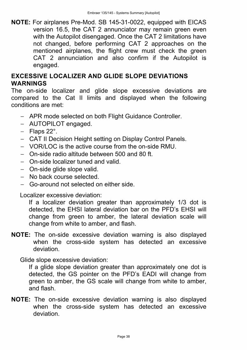
NOTE: For airplanes Pre-Mod. SB 145-31-0022, equipped with EICASversion 16.5, the CAT 2 annunciator may remain green evenwith the Autopilot disengaged. Once the CAT 2 limitations havenot changed, before performing CAT 2 approaches on thementioned airplanes, the flight crew must check the greenCAT 2 annunciation and also confirm if the Autopilot isengaged.
EXCESSIVE LOCALIZER AND GLIDE SLOPE DEVIATIONSWARNINGSThe on-side localizer and glide slope excessive deviations arecompared to the Cat II limits and displayed when the followingconditions are met:
− APR mode selected on both Flight Guidance Controller.− AUTOPILOT engaged.− Flaps 22°.− CAT II Decision Height setting on Display Control Panels.− VOR/LOC is the active course from the on-side RMU.− On-side radio altitude between 500 and 80 ft.− On-side localizer tuned and valid.− On-side glide slope valid.− No back course selected.− Go-around not selected on either side.
Localizer excessive deviation:If a localizer deviation greater than approximately 1/3 dot isdetected, the EHSI lateral deviation bar on the PFD’s EHSI willchange from green to amber, the lateral deviation scale willchange from white to amber, and flash.
NOTE: The on-side excessive deviation warning is also displayedwhen the cross-side system has detected an excessivedeviation.
Glide slope excessive deviation:If a glide slope deviation greater than approximately one dot isdetected, the GS pointer on the PFD’s EADI will change fromgreen to amber, the GS scale will change from white to amber,and flash.
NOTE: The on-side excessive deviation warning is also displayedwhen the cross-side system has detected an excessivedeviation.
Embraer 135/145 - Systems Summary [Autopilot]
Page 38
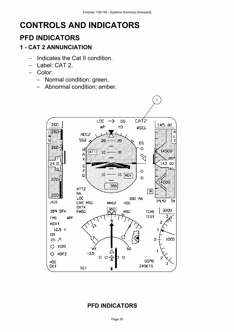
CONTROLS AND INDICATORSPFD INDICATORS1 - CAT 2 ANNUNCIATION
− Indicates the Cat II condition.− Label: CAT 2.− Color:
− Normal condition: green.− Abnormal condition: amber.
PFD INDICATORS
Embraer 135/145 - Systems Summary [Autopilot]
Page 39
Ludo
Tampon