
Embedded Microcomputer Systems: Real Time …users.ece.utexas.edu/~valvano/ExtraQuestions.pdfReal...
39
Embedded Microcomputer Systems: Real Time Interfacing, Second Edition Supplementary Questions Jonathan W. Valvano
Transcript of Embedded Microcomputer Systems: Real Time …users.ece.utexas.edu/~valvano/ExtraQuestions.pdfReal...

Embedded Microcomputer Systems: Real Time Interfacing, Second Edition
Supplementary Questions
Jonathan W. Valvano

2 Supplementary Questions for Real Time Embedded Systems, 2nd Edition
The material in this book is for educational purposes only. The programs and circuits in this manual have not been built or tested. They are provided without guarantee with respect to their accuracy. You are free to use the programs and circuits for either educational or commercial purposes, but please do not post these answers on the web or distribute them to others.
5. Disillusionment
!!??++!!!
executing
3. Love2. Excitement
no compile errors
1. Distrust
Welcome...
crash!
4. Surprise 6. Frustration
error
oh man!
J Vw
Interrupt programming can be frustrating.
Each chapter has a number of additional questions and answers. Students can access the extra questions from www.ece.utexas.edu/~valvano (click on the extra questions link). Instructors can receive a Microsoft Word file containing these extra questions. If you find mistakes, please contact me at [email protected]. Jonathan W. Valvano Good luck

Jonathan W. Valvano 3
Table of Contents Chapter 1. Extra Questions ............................................................................................................4
Chapter 2 Extra Questions .............................................................................................................6
Chapter 3 Extra Questions .............................................................................................................9
Chapter 4 Extra Questions ...........................................................................................................10
Chapter 5 Extra Questions ...........................................................................................................16
Chapter 6 Extra Questions ...........................................................................................................22
Chapter 7 Extra Questions ...........................................................................................................23
Chapter 8 Extra Questions ...........................................................................................................25
Chapter 9 Extra Questions ...........................................................................................................28
Chapter 10 Extra Questions .........................................................................................................30
Chapter 11 Extra Questions .........................................................................................................31
Chapter 12 Extra Questions .........................................................................................................33
Chapter 13 Extra Questions .........................................................................................................36
Chapter 14 Extra Questions .........................................................................................................38
Chapter 15 Extra Questions .........................................................................................................39
I just provedthis algorithmis correct!
Good Ben, butshouldn't youactually run it?

4 Supplementary Questions for Real Time Embedded Systems, 2nd Edition
Chapter 1. Extra Questions Extra Question 1.34. Design a circuit that interfaces a 2.4V 12mA LED to YourComputer. Extra Question 1.35. Design a circuit that interfaces a 2.2V 15mA LED to YourComputer. Extra Question 1.36. Design a circuit that interfaces a 2.1V 10mA LED to YourComputer. Extra Question 1.37. Assume, you are given the 6812 voltage and current parameters for PT0: VOH, VOL, VIH, VIL, IOH, IOL, IIH, and IIL. The desired LED voltage is VD and the desired current is ID. Assume the LED current is small enough, so the LED can be interfaced directly to the 6812 PT0 pin as shown. Give the equation to calculate the resistance R in terms of VD, ID, VOH, VOL, VIH, VIL, IOH, IOL, IIH, and IIL. Extra Question 1.38. Assume, you are given the 6812 voltage and current parameters for PT1: VOH, VOL, VIH, VIL, IOH, IOL, IIH, and IIL. The desired LED voltage is VD and the desired current is ID. Assume the LED current is small enough, so the LED can be interfaced directly to the 6812 PT1 pin as shown. Give the equation to calculate the resistance R in terms of VD, ID, VOH, VOL, VIH, VIL, IOH, IOL, IIH, and IIL. Extra Question 1.39. If a system uses a 15-bit ADC, about how many decimal digits will it have? Extra Question 1.40. If a system uses a 16-bit ADC, about how many decimal digits will it have? Extra Question 1.41. If a system requires 2¾ decimal digits of precision, what is the smallest number of bits the ADC needs to have? Extra Question 1.42. The resolution of an 8-bit unsigned binary fixed-point number is 2-2, which equals 1/4. What is the value of the number if the integer stored in memory is 81? Extra Question 1.43. Assume you are going to use a 16-bit signed decimal fixed-point number system to represent the values from -1000 to +1000. What is the smallest fixed-point resolution you could use? Extra Question 1.44. A signed fixed point system has a range of values from -50 to +50 with a resolution of 2-8. Note: 2-8 equals 1/256. With which of the following data types should the software variables be allocated? When more than one answer is possible choose the most space efficient type. A) char B) unsigned char C) float D) short E) unsigned short F) double G) long H) unsigned long Extra Question 1.45. Write software that initializes 6812 Port T, so pins 2 and 3 are output without affecting the other 6 bits. Extra Question 1.46. Write software that initializes 6812 Port T, so pins 7 and 0 are inputs without affecting the other 6 bits. Extra Question 1.47. Write software that initializes 6812 Port T, so all the pins are output, then outputs the repeating sequence $E0, $3C, $07. This software outputs the sequence over and over without stopping. Extra Question 1.48. Does the associative principle hold for signed integer multiply and divide? In particular do these two C calculations always achieve identical outputs? If no, give an example. Out1 = (A*B)/C; Out2 = A*(B/C);
+5V
PT1R
PT0
R

Jonathan W. Valvano 5
Extra Question 1.49. Does the associative principle hold for signed integer addition and subtraction? In particular do these two C calculations always achieve identical outputs? If no, give an example. Out3 = (A+B)-C; Out4 = A+(B-C); Extra Question 1.50. In this question the input parameter is the temperature, TC, which is a 16-bit signed binary fixed-point number with a resolution of 1/8 ºC. The integer portion of this parameter is stored in memory as the variable Ic. The output of this function will be the temperature, TF, which is a 16-bit signed binary fixed-point number with a resolution of 1/8 ºF. Write C code that implements the conversion from ºC to ºF using fixed-point math. In particular, calculate TF =1.8*TC +32º. The function operates on the integer portion of the fixed point numbers. You may assume the input temperature range is bounded -50 < TC < +100 ºC. The prototype is short Convert(short Ic); // convert Ic to If Extra Question 1.51. In this question the input parameter is the temperature, TC, which is a 16-bit signed binary fixed-point number with a resolution of 1/16 ºC. The integer portion of this parameter is stored in memory as the variable Ic. The output of this function will be the temperature, TF, which is a 16-bit signed binary fixed-point number with a resolution of 1/16 ºF. Write C code that implements the conversion from ºC to ºF using fixed-point math. In particular, calculate TF =1.8*TC +32º. The function operates on the integer portion of the fixed point numbers. You may assume the input temperature range is bounded -20 < TC < +50 ºC. The prototype is short Convert(short Ic); // convert Ic to If Extra Question 1.52. In this question the input parameter is the temperature, TF, which is a 16-bit signed binary fixed-point number with a resolution of 1/8 ºF. The integer portion of this parameter is stored in memory as the variable If. The output of this function will be the temperature, TC, which is a 16-bit signed binary fixed-point number with a resolution of 1/8 ºC. Write C code that implements the conversion from ºF to ºC using fixed-point math. In particular, calculate TC =(5/9)*(Tf -32º). The function operates on the integer portion of the fixed point numbers. You may assume the input temperature range is bounded -40 < TF < +120 ºF. The prototype is short Convert(short If); // convert If to Ic Extra Question 1.53. In this question the input parameter is the temperature, TF, which is a 16-bit signed binary fixed-point number with a resolution of 1/16 ºF. The integer portion of this parameter is stored in memory as the variable If. The output of this function will be the temperature, TC, which is a 16-bit signed binary fixed-point number with a resolution of 1/16 ºC. Write C code that implements the conversion from ºF to ºC using fixed-point math. In particular, calculate TC =(5/9)*(Tf -32º). The function operates on the integer portion of the fixed point numbers. You may assume the input temperature range is bounded -40 < TF < +120 ºF. The prototype is short Convert(short If); // convert If to Ic
6 Supplementary Questions for Real Time Embedded Systems, 2nd Edition
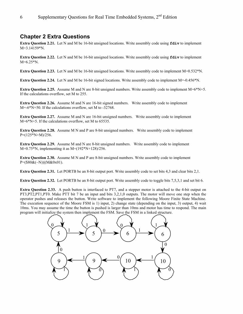
Chapter 2 Extra Questions Extra Question 2.21. Let N and M be 16-bit unsigned locations. Write assembly code using fdiv to implement M=3.14159*N. Extra Question 2.22. Let N and M be 16-bit unsigned locations. Write assembly code using fdiv to implement M=6.25*N. Extra Question 2.23. Let N and M be 16-bit unsigned locations. Write assembly code to implement M=0.532*N. Extra Question 2.24. Let N and M be 16-bit signed locations. Write assembly code to implement M=-0.456*N. Extra Question 2.25. Assume M and N are 8-bit unsigned numbers. Write assembly code to implement M=6*N+5. If the calculations overflow, set M to 255. Extra Question 2.26. Assume M and N are 16-bit signed numbers. Write assembly code to implement M=-6*N+50. If the calculations overflow, set M to -32768. Extra Question 2.27. Assume M and N are 16-bit unsigned numbers. Write assembly code to implement M=6*N+5. If the calculations overflow, set M to 65535. Extra Question 2.28. Assume M N and P are 8-bit unsigned numbers. Write assembly code to implement P=(125*N+M)/256. Extra Question 2.29. Assume M and N are 8-bit unsigned numbers. Write assembly code to implement M=0.75*N, implementing it as M=(192*N+128)/256. Extra Question 2.30. Assume M N and P are 8-bit unsigned numbers. Write assembly code to implement P=($80&(~N))|(M&0x01). Extra Question 2.31. Let PORTB be an 8-bit output port. Write assembly code to set bits 4,3 and clear bits 2,1. Extra Question 2.32. Let PORTB be an 8-bit output port. Write assembly code to toggle bits 7,5,3,1 and set bit 6. Extra Question 2.33. A push button is interfaced to PT7, and a stepper motor is attached to the 4-bit output on PT3,PT2,PT1,PT0. Make PTT bit 7 be an input and bits 3,2,1,0 outputs. The motor will move one step when the operator pushes and releases the button. Write software to implement the following Moore Finite State Machine. The execution sequence of the Moore FSM is 1) input, 2) change state (depending on the input, 3) output, 4) wait 10ms. You may assume the time the button is pushed is larger than 10ms and motor has time to respond. The main program will initialize the system then implement the FSM. Save the FSM in a linked structure.
5 6
109
5 6
109
0
0
00
0
0
0
01
1
1
1
1
111

Jonathan W. Valvano 7
Extra Question 2.34. Consider the following Mealy FSM, where the initial state is A. The labels on the arrows mean input/output. If the input were to be a constant 1, describe the sequence of states and outputs until a repeating pattern is established.
A B C0/0
1/0
1/1
0/1
1/10/0
Extra Question 2.35. You will implement this traffic light finite state machine. Each state has a 4-bit output value, and four next state pointers. The sequence is output, wait, input, next.
wait time in seconds
01,1100,10west
45
00,01
0x09 0x06north
20output
state number
10,11
next state if input is 01 or 11
The hardware uses 4 bits of PORTT and 2 bits of Port M, so your software will configure the two direction registers in a friendly manner. You may call the timer delay functions presented in Chapter 2.
PT3PT2PT1PT0
PM1PM0
6812 lights
sensors
Street
Extra Question 2.36. You will design a finite state machine to implement this line-tracking robot. Each state has a 2-bit output value, and four next state pointers.
next if input is 1 or 3
S0 S111
0x02 0x03
01,11
output
state number
0100
00,10S2
0x0110,11
0001
10
The hardware uses 4 bits of Port T, so your software will configure Port T bits 1,0 to be outputs and bits 3,2 to be input. The other four bits of Port T should not be modified (i.e., write friendly software.)
PT1PT0
PT3PT2
6812wheel motors
track sensors
You will design the linked data structure, and write the main program (no interrupts and no time delays) that executes the Moore finite state machine. S1 is the initial state. Extra Question 2.37. You will write software that outputs data to a LCD display. You may write it in assembly or in C. The data are ASCII characters. The ritual should set the direction registers for ports A and B. All operations should be friendly. The hardware connections are as follows: PA7 --> start your software sets this high to start an I/O operation PA6 <-- done this signal goes high when the I/O operation is complete PB7-PB0 --> data output to display

8 Supplementary Questions for Real Time Embedded Systems, 2nd Edition
To output a letter to the LCD (if you are using assembly, assume the data is passed in RegA), 1) write Port B with the 8-bit data to display, 2) set start high 3) wait for done to be 1 4) set start low 5) wait for done to be 0

Jonathan W. Valvano 9
Chapter 3 Extra Questions Extra Question 3.20. Interface a 74HC595 shift register to Port C of the microcontroller. Connect the 74HC595 Rclk latch (pin 12) to PC2, the 74HC595 Sck clock (pin 11) to PC1, and the 74HC595 SER input data (pin 14) to PC0. Ground 74HC595 Sclr (pin 10) and 74HC595 G (pin 13). Write a ritual function that initializes the interface, and an output function that outputs 8 bits to the shift register. Extra Question 3.21. Write a routine that outputs a fixed point position to the SCI port. The resolution of the number system is 0.01 cm, and the precision is 8 bits. The range is 0.00 cm to 2.55 cm. You may assume the SCI is initialized and you may call the SCI_OutChar and SCI_OutString functions. Your routine is passed the integer portion of the fixed-point number (0 to 255). Extra Question 3.22. Write a routine that outputs a fixed point temperature to the SCI port. The resolution of the number system is 0.1 C, and the precision is 16 bits. The range is -99.9 to 99.9 C. You may assume the SCI is initialized and you may call the SCI_OutChar and SCI_OutString functions. Your routine is passed the integer portion of the fixed-point number (-999 to 999). For example, if the integer is -5, then output "-0.5 C". For example, if the integer is 123, then output "12.3 C". Extra Question 3.23. Write a new SCI_InChar function that inputs a character from the SCI receiver, but will timeout after waiting 1 second. If a character arrives within the 1 second interval the function terminates immediately returning the character received. On the other hand, if no character arrives within the 1 second interval the function returns a value of 0. You may assume TCNT has been initialized to count every 1 µs. Extra Question 3.24. Assume the MCLK on a 9S12C32 is 4MHz. Part a) What are the slowest and fastest possible baud rates? Part b) Write a SCI_Init initialization routine that takes an arbitrary baud rate. I.e., the prototype is void SCI_Init(unsigned long baudRate); The protocol is 1 start bit, 8 data bits, no parity and 1 stop bit. Extra Question 3.25. Assume the MCLK on a 9S12C32 is 24MHz. Part a) What are the slowest and fastest possible baud rates? Part b) Write a SCI_Init initialization routine that takes an arbitrary baud rate. I.e., the prototype is void SCI_Init(unsigned long baudRate); The protocol is 1 start bit, 8 data bits, no parity and 1 stop bit.
10 Supplementary Questions for Real Time Embedded Systems, 2nd Edition
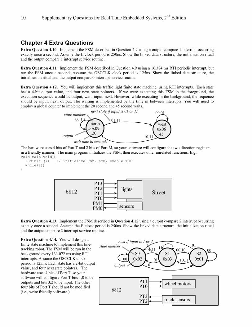
Chapter 4 Extra Questions Extra Question 4.10. Implement the FSM described in Question 4.9 using a output compare 1 interrupt occurring exactly once a second. Assume the E clock period is 250ns. Show the linked data structure, the initialization ritual and the output compare 1 interrupt service routine. Extra Question 4.11. Implement the FSM described in Question 4.9 using a 16.384 ms RTI periodic interrupt, but run the FSM once a second. Assume the OSCCLK clock period is 125ns. Show the linked data structure, the initialization ritual and the output compare 0 interrupt service routine. Extra Question 4.12. You will implement this traffic light finite state machine, using RTI interrupts. Each state has a 4-bit output value, and four next state pointers. If we were executing this FSM in the foreground, the execution sequence would be output, wait, input, next. However, while executing in the background, the sequence should be input, next, output. The waiting is implemented by the time in between interrupts. You will need to employ a global counter to implement the 20 second and 45 second waits.
The hardware uses 4 bits of Port T and 2 bits of Port M, so your software will configure the two direction registers in a friendly manner. The main program initializes the FSM, then executes other unrelated functions. E.g., void main(void) FSMinit (); // initialize FSM, arm, enable TOF while(1)
PT3PT2PT1PT0
PM1PM0
6812 lights
sensors
Street
Extra Question 4.13. Implement the FSM described in Question 4.12 using a output compare 2 interrupt occurring exactly once a second. Assume the E clock period is 250ns. Show the linked data structure, the initialization ritual and the output compare 2 interrupt service routine. Extra Question 4.14. You will design a finite state machine to implement this line-tracking robot. The FSM will be run in the background every 131.072 ms using RTI interrupts. Assume the OSCCLK clock period is 125ns. Each state has a 2-bit output value, and four next state pointers. The hardware uses 4 bits of Port T, so your software will configure Port T bits 1,0 to be outputs and bits 3,2 to be input. The other four bits of Port T should not be modified (i.e., write friendly software.)
wait time in seconds
01,1100,10west
45
00,01
0x09 0x06north
20output
state number
10,11
next state if input is 01 or 11
next if input is 1 or 3
S0 S111
0x02 0x03
01,11
output
state number
0100
00,10S2
0x0110,11
0001
10
PT1PT0
PT3PT2
6812wheel motors
track sensors

Jonathan W. Valvano 11
You will design the linked data structure, storing it in ROM.. S1 is the initial state. The main program initializes the FSM, then executes other unrelated functions. E.g., void main(void) FSMinit (); // initialize FSM, arm, enable RTI while(1) Extra Question 4.15. Implement the FSM described in Question 4.14 using a 100 ms output compare 3 interrupt. Assume the E clock period is 250ns. Show the linked data structure, the initialization ritual and the output compare 3 interrupt service routine. Extra Question 4.16. You will implement this Mealy finite state machine. There is one digital input signal (connected to PTM bit 0) and eight digital output signals (connected to PTT). The sequence is wait, input, output, go to next state, wait, input, output, go to next state, wait… where the waiting occurs using output compare interrupt 1. You may assume the system is running at 4 MHz, i.e., the PLL was not activated. State S0 is the initial state. Make the accesses to Port M friendly. You will write the entire software system to run this FSM. You must use the following data structure that defines the FSM. After initialization, all input, output, and waiting occur in the output compare interrupt service routine. You cannot call any functions, unless you explicitly define those functions in your solution. The main program initializes the system, and the controller runs in the background. Extra Question 4.17. Find the sequence of execution that leads to the incorrect value being displayed. Display is a function that is called from the foreground, while RTIHan is a background interrupt service routine periodically activated by the RTIF flag. If the interrupt occurs at a bad time, and Time is a certain value, then Display will output an incorrect value. Part a) Sort the C code with a “1”, “2”, “3”,… symbol signifying the order of execution that yields a bad display. Also specify the value of Time before the interrupt (there is more than one). unsigned short Time; void Display(void) // called from the foreground SCI_OutChar(Time/10+0x30); // tens SCI_OutChar(Time%10+0x30); // ones void interrupt 7 RTIHan(void) Time++; // 0 to 59 if(Time == 60) Time = 0; CRGFLG = 0x80; // acknowledge Part b) Rewrite the Display function to eliminate the bug. Extra Question 4.18. The overall goal is to draw a picture of the stack that exists while in the middle of the RTIHan. First, compile this C program and observe the assembly listing the compiler generates. Starting at the top of main, hand-execute this software system; main calls function; the RTI interrupt occurs at the specified spot within function, and the RTIHan runs until the “show stack” comment. Local variables, parameters, and return values will be pushed on the stack. For each element pushed on the stack, give a general symbolic description (e.g., return pointer, old X, i1, f0) rather than its specific value (e.g., $F08A, $0000, 100, 4.) void interrupt 7 RTIHan(void) short i1; short static i2=100; i2--; i1 = i2; // show stack at this point if(i1 == 0 ) i2=100; RTIFLG = 0x80; short function(short f0) short f1; f1 = f0+4; // interrupt occurs here
if input is
wait time
0/$221/$87S1
500µsS0
300µs
then the output is
state number
S2200µs
0/$5F1/$00
0/$9C
1/$E4

12 Supplementary Questions for Real Time Embedded Systems, 2nd Edition
return f1; void main(void) short m1; m1 = function(4); while(1); Extra Question 4.19. Assume the foreground thread calls SetBit0() (with interrupts enabled) and a single background thread calls SetBit1(). Is there a critical section? Justify your answer. void SetBit1(void) PTT = PTT|0x02; void SetBit0(void) PTT = PTT|0x01; Extra Question 4.20. Why don't you disable interrupts at the start of an ISR by executing sei, and re-enable interrupts at the end of the ISR by executing cli? Extra Question 4.21. What happens if an interrupt service routine does not acknowledge or disarm? Extra Question 4.22. List the events in proper order as a RTI interrupt causes the computer to switch from foreground to background? Do not include events explicitly caused by executing software in either the foreground or in the background, just the hardware events occurring during the context switch. A) The I bit is cleared to zero (enable) B) The PC is loaded with the 16-bit contents of $FFF0 C) The RTI interrupts are armed by setting the RTIE bit in the CRGINT register D) The PC, Y, X, B, A, CC registers are pulled from the stack E) The CC, A, B, X, Y, PC registers are pushed on the stack F) The I bit is set to one (disable) G) The PC is set equal to $FFF0 H) A write with bit 7=0 occurs to CRGFLG, clearing RTIF I) A write with bit 7=1 occurs to CRGFLG, clearing RTIF J) The periodic timer clock times out, setting RTIF Extra Question 4.23. Consider the case of an interrupt-driven input interface as shown in Figure 4.4. The Fifo queue is used to buffer the data between the background (the producer is the input interrupt service routine that calls PutFifo) and the foreground (the consumer is the main program that calls GetFifo). The average producer rate is 10 bytes/sec. E.g., the human operator can type 10 characters/sec. The average time for the foreground software to process each character is 1 second. I.e., the average rate at which the foreground calls GetFifo is 1 Hz. The system does not work properly, and the purpose of this question is to evaluate the problem, and suggest a correction. Part a) Is the system I/O bound or CPU bound? Part b) Are any data lost? If so, explain what is happening. If data is not lost, explain what the problem is. Part c) Can the problem be fixed by increasing the Fifo size? If not, suggest an effective way to correct the problem. Extra Question 4.24. Consider the situation where interrupt-driven I/O uses a Fifo to transmit data between the foreground and the background as shown in Figure 4.4. The producer generates data and puts it into the Fifo, concurrently with the consumer getting data from the Fifo and processing it. Observations of the system reveal the FIFO becomes full. Which best describes the situation? A) The problem can always be solved by increasing the size of the Fifo . B) The problem can never be solved by increasing the size of the Fifo . C) The problem can always be solved by increasing the producer rate. D) The problem can always be solved by increasing the interrupt rate. E) Sometimes the problem can be solved by increasing the size of the Fifo, but other times it will be necessary to increase the consumer rate or decrease the producer rate. Extra Question 4.25. You will be using the switch attached to PAD7 and the LED attached to PT0. The LED should be initially off, and the LED should be turned on (and left on) when the operator pushes the switch five (5) times. The goal of this question is to write RTI interrupt-based software that counts the number of times the switch is pushed, and turns the LED on if the switch is pushed five (5) times. When the switch is pushed, the input on
Jonathan W. Valvano 13
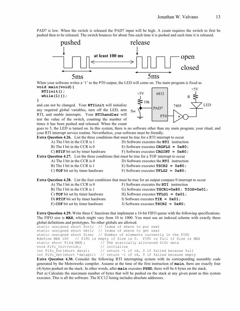
PAD7 is low. When the switch is released the PAD7 input will be high. A count requires the switch to first be pushed then to be released. The switch bounces for about 5ms each time it is pushed and each time it is released.
pushed r e l e a s e
5 m s 5 m s
o p e n
c l o s e d
at least 100 ms
When your software writes a ‘1’ to the PT0 output, the LED will come on. The main program is fixed as void main(void) RTIinit(); while(1); and can not be changed. Your RTIinit will initialize any required global variables, turn off the LED, arm RTI, and enable interrupts. Your RTIhandler will test the value of the switch, counting the number of times it has been pushed and released. When the count goes to 5, the LED is turned on. In this system, there is no software other than my main program, your ritual, and your RTI interrupt service routine. Nevertheless, your software must be friendly. Extra Question 4.26. List the three conditions that must be true for a RTI interrupt to occur A) The I bit in the CCR is 1 D) Software executes the RTI instruction B) The I bit in the CCR is 0 E) Software executes CRGFLG = 0x80; C) RTIF bit set by timer hardware F) Software executes CRGINT = 0x80; Extra Question 4.27. List the three conditions that must be true for a TOF interrupt to occur A) The I bit in the CCR is 0 D) Software executes the RTI instruction B) The I bit in the CCR is 1 E) Software executes TSCR2 = 0x80; C) TOF bit set by timer hardware F) Software executes TFLG2 = 0x80; Extra Question 4.28. List the four conditions that must be true for an output compare 0 interrupt to occur A) The I bit in the CCR is 0 F) Software executes the RTI instruction B) The I bit in the CCR is 1 G) Software executes TSCR1=0x80; TIOS=0x01; C) TOF bit set by timer hardware H) Software executes TFLG1 = 0x01; D) RTIF bit set by timer hardware I) Software executes TIE = 0x01; E) C0F bit set by timer hardware J) Software executes TSCR2 = 0x80; Extra Question 4.29. Write three C functions that implement a 16-bit FIFO queue with the following specifications. The FIFO size is MAX, which might vary from 10 to 1000. You must use an indexed scheme with exactly these global definitions and prototypes. No other globals are allowed. static unsigned short PutI; // Index of where to put next static unsigned short GetI; // Index of where to get next static unsigned short Size; // Number of elements currently in the FIFO #define MAX 100 // FIFO is empty if Size is 0. FIFO is full if Size is MAX static short Fifo[MAX]; // The statically allocated fifo data void Fifo_Init(void); // initialize int Fifo_Put(short data); // return -1 if ok, 0 if failed because full int Fifo_Get(short *datapt); // return -1 if ok, 0 if failed because empty Extra Question 4.30. Consider the following RTI interrupting system with its corresponding assembly code generated by the Metrowerks compiler. Assume at the time of the first instruction of main, there are exactly four (4) bytes pushed on the stack. In other words, after main executes PSHD, there will be 6 bytes on the stack. Part a) Calculate the maximum number of bytes that will be pushed on the stack at any given point as this system executes. This is all the software. The ICC12 listing includes absolute addresses.
+5V
10kPAD7
R
+5V
7405 LED
PT0
6812
Sw

14 Supplementary Questions for Real Time Embedded Systems, 2nd Edition
short Num; short LowPassFilter(const short in) static short ans; ans = (in+ans)/2; return ans; void interrupt 7 handler() CRGFLG = 0x80; Num++; Num = LowPassFilter(Num); void main(void)short out; CRGINT = 0x80; RTICTL = 0x33; Num = 0; asm cli for(;;) out = LowPassFilter(Num);
LowPassFilter 4100 3b PSHD 4101 fc3802 LDD ans 4104 e380 ADDD 0,SP 4106 ce0002 LDX #2 4109 1815 IDIVS 410b 7e3802 STX ans 410e b754 TFR X,D 4110 30 PULX 4111 3d RTS handler 4112 c680 LDAB #128 4114 5b37 STAB _CRGFLG 4116 fe3800 LDX Num 4119 08 INX 411a 7e3800 STX Num 411d fc3800 LDD Num 4120 07de BSR LowPassFilter 4122 7c3800 STD Num 4125 0b RTI Main ; <=start execution here 4126 3b PSHD 4127 c680 LDAB #128 4129 5b38 STAB _CRGINT 412b 8633 LDAA #51 412d 5a3b STAA _RTICTL 412f c7 CLRB 4130 87 CLRA 4131 7c3800 STD Num 4134 10ef CLI 4136 fc3800 LDD Num 4139 07b3 BSR LowPassFilter 413b 6c80 STD 0,SP 413d 20f7 BRA *-7
Part b) Is there a critical section? If so, state the two assembly instructions between which the critical section exists. Part c) What does the const qualifier in the function LowPassFilter() mean? A) private in scope B) the value is fixed and can not be changed by the function C) stored in ROM D) tells the compiler to fetch a new value, and do not optimize E) stored in global RAM F) promoted to the next high precision Part d) What does the static qualifier in the function LowPassFilter() mean? A) private in scope B) the value is fixed and can not be changed by the function C) stored in ROM D) tells the compiler to fetch a new value, and do not optimize E) stored in global RAM F) promoted to the next high precision Part e) What is the programming bug in the function LowPassFilter()? A) potential dropout in division B) type mismatch in adding in+ans C) potential overflow in addition D) uninitialized variable ans E) type mismatch in return ans F) there are no errors in this program Part f) LowPassFilter() is called from an ISR as part of a real-time system. The SCI, PTT and PTAD are unused by the system, and PTT and PTAD are digital outputs. The debugging code will be placed at the end just before the return, unless otherwise stated. SCI_OutSDec outputs a 16-bit signed integer. BufX and BufY are global buffers of length 200, n is a global variable initialized to 0. Which debugging code would you add to verify the correctness of this function? A) PTT=in; PTAD=ans; B) if(n<200)BufX[n]=in; BufY[n]=ans; n++; C) SCI_OutSDec(in); SCI_OutSDec(ans); // busy-wait D) SCI_OutSDec(in); SCI_OutSDec(ans); // interrupt driven E) PTT |= 0x01; // at beginning PTT &= ~0x01; // at end

Jonathan W. Valvano 15
F) PTT ^= 0x01; // at beginning PTT ^= 0x02; // at end Extra Question 4.31. Consider the situation where interrupt-driven I/O uses a fifo if size n to transmit data between the foreground and the background as shown in Figure 4.4. The producer generates data and puts it into the fifo, concurrently with the consumer getting data from the fifo and processing it. Assume the fifo is initially empty, the producer rate is given by the time-varying function, rP(t) and the consumer rate is given by the time-varying function, rG(t). If rP(t)>rG(t) at all times, derive an equation that could be used to determine the time it takes to fill the fifo. Extra Question 4.32. The following code was used to acknowledge a timer channel 5 interrupt. Which explanation best describes this code? TFLG1 |= 0x20; A) This software only makes the C5F bit high. It is friendly. B) This software only makes the C5F bit low. It is friendly. C) This software will make all flag bits high in the TFLG1 register. It is not friendly. D) This software will make all flag bits low in the TFLG1 register. It is not friendly. E) This will cause a compile error because the software can not set flag bits in the TFLG1 register. F) This will cause a run-time crash, because the software can not set flag bits in the TFLG1 register. G) This will cause a run-time crash, because it clears all the flag bits in the TFLG1 register except C5F. Extra Question 4.33. The following code was used to acknowledge a timer channel 5 interrupt. Which explanation best describes this code? TFLG1 &= ~0x20; A) This software only makes the C5F bit high. It is friendly. B) This software only makes the C5F bit low. It is friendly. C) This software will make all flag bits high in the TFLG1 register. It is not friendly. D) This software will make all flag bits low in the TFLG1 register. It is not friendly. E) This will cause a compile error because the software can not set flag bits in the TFLG1 register. F) This will cause a run-time crash, because the software can not set flag bits in the TFLG1 register. G) This will cause a run-time crash, because it clears all the flag bits in the TFLG1 register except C5F.

16 Supplementary Questions for Real Time Embedded Systems, 2nd Edition
Chapter 5 Extra Questions Extra Question 5.5. In this question, you will design a Sleep OS primitive. A thread will put itself to sleep for a fixed amount of time in msec when it doesn't need to run any more at this point. The basic idea is the thread calls OS_Sleep specifying how long it wishes to remain dormant. E.g., executing OS_Sleep(2000); will cause this thread not to be run in the next 2000 ms. At the end of the sleep interval, it is not guaranteed to run at that exact time, but rather its status is made active again, allowing it to be run. This concept is similar to the preemption-points added for cooperative multitasking. If fact, a preemption-point could be implemented simply by calling OS_Sleep(0); You may assume an unsigned 16-bit value called SleepCounter has been added to each TCB. When the SleepCounter is zero, the thread can be run. A nonzero value specifies the time in ms until the thread awakes. Also, you may assume the OS_AddThread function will initialize this value to 0. You will need an additional periodic interrupt process using output compare 0 that implements the sleep waiting. Part a) Show the implementation of the OS_Sleep function. Calling this function will set the SleepCounter value in the TCB and cause a preemption (this thread stops running). The prototype is void OS_Sleep(unsigned short delay); Part b) Rewrite the threadSwitch for this new system, which will not run any thread with a nonzero SleepCounter. You may assume there is at least one thread that never blocks or sleeps. Part c) Design an OC0 ISR that implements sleeping. Once every ms, this ISR will decrement the SleepCounter for all threads with a nonzero SleepCounter. Extra Question 5.6. In this problem, you will modify the OS so the memory for the TCB is dynamically allocated on the heap. In particular, there will be no NumThread MAX_THREADS or SystemTCB. Instead, you should define a pointer TCBPtr pt; and execute the code pt=malloc(sizeof(TCBType)); to create a new TCB. malloc returns a NULL (0) pointer when the heap is full. You may assume RunPt is defined and initialized to NULL (0). To return the memory back to the heap, execute free(pt); Part a) Write a new OS_AddThread that dynamically allocates space and links it into the circular active TCB list. If RunPt is NULL (0), this is the first thread created. Additional global variables are allowed. Part b) Write a new function OS_Kill that a thread can call to kill itself. Return the TCB to the heap, reconstruct the circular TCB list, and launch another thread. You may assume there is at least one active thread (all the threads do not die.) Extra Question 5.7. Consider two different systems running foreground threads using a preemptive scheduler with semaphore synchronization. There are two shared 16-bit global variables which contain the position of an object: short TheX,TheY; Both, the client and server wish to access this data. The basic shell of this operation is given. Define one or more semaphores, then add calls to the following three functions in order to properly synchronize the interactions between client and server. The goal is to prevent corrupted data. If you wish to make no changes at all, explain why, otherwise for each semaphore you add, explain what it means to be 0, 1 etc. int OS_InitSemaphore(Sema4Type *semaPt, short value); void OS_Wait(Sema4Type *semaPt); void OS_Signal(Sema4Type *semaPt); Part a) You will define one or more semaphores and calls to the semaphore functions, otherwise no other changes are allowed. Assume server is run first. You may assume the only accesses to TheX and TheY in the entire software system are explicitly shown here. void server(void) short sX,sY; TheX = 5; TheY = 6; sInit(); // initialization while(1) sX= TheX; sY= TheY; sProcess(&sX,&sY); // body
void client(void) short cX,cY; cInit(); // initialization while(1) cX= TheX; cY= TheY; cProcess(cX,cY); // body

Jonathan W. Valvano 17
Part b) You will define one or more semaphores and calls to the semaphore functions, otherwise no other changes are allowed. Assume server is run first. You may assume the only accesses to TheX and TheY in the entire software system are explicitly shown here. void server(void) short sX,sY; sX = 5; sY = 6; sInit(); // initialization while(1) TheX = sX; TheY = sY; sProcess(&sX,&sY); // body
void client(void) short cX,cY; cInit(); // initialization while(1) cX= TheX; cY= TheY; cProcess(cX,cY); // body
Extra Question 5.8. What bad thing might happen if OS_Wait does not disable interrupts? I.e., what can go wrong with the following spinlock implementation? void OS_Wait(Sema4Type *semaPt) while(semaPt->Counter <= 0) (semaPt->Counter)--; Extra Question 5.9. Select the best term that describes each definition. Part a) The condition where once a thread blocks, there are a finite number of threads that will be allowed to proceed before this thread is allowed to proceed. Part b) A technique to periodically increase the priority of low-priority threads so that low priority threads occasionally get run. The increase is temporary. Part c) The condition where low priority threads never get run. Part d) The condition where thread 1 is waiting for a resource held by thread 2, and thread 2 is waiting for a resource held by thread 1. Part e) The condition where a thread is prevented from running, because it needs something that is unavailable. Part f) A place in the software, where if an interrupt or thread switch were to occur, data would be lost or corrupted. Part g) Software that can be concurrently executed by multiple threads. Part h) A mechanism that implements equal priority amoung threads.
word bank active aging blocked bounded buffer bounded waiting critical section deadlock killed maximum latency
nonrentrant preemptive scheduler producer-consumer reentrant rendezvous round robin scheduler sleeping spin lock starvation
Extra Question 5.10. Consider a problem of running three foreground threads using a preemptive scheduler with semaphore synchronization. Each thread has a central body() containing code that should be executed together. The basic shell of this system is given. Define one or more semaphores, then add semaphore function calls to implement a three-thread rendezvous. Basically, each time through the while loop, the first two threads to finish their start() code will wait for the last thread to finish its start() code. Then, all three threads will be active at the same time as they execute their corresponding body().You will define one or more semaphores and add calls to these three semaphore functions, otherwise no other changes are allowed. You may assume thread1 runs first. If you wish to make no changes at all, explain why, otherwise for each semaphore you add, explain what it means to be 0, 1 etcThe semaphore prototypes: void Init (Sema4Type *semaPt, short value); void Wait(Sema4Type *semaPt); void Signal(Sema4Type *semaPt);

18 Supplementary Questions for Real Time Embedded Systems, 2nd Edition
void thread1(void) init1(); while(1) start1(); body1(); end1();
void thread2(void) init2(); while(1) start2(); body2(); end2();
void thread3(void) init3(); while(1) start3(); body3(); end3();
Extra Question 5.11. Consider a problem of running two foreground threads using a preemptive scheduler with semaphore synchronization. There are two shared 16-bit global variables which contain the position of an object: short TheX,TheY; Both, the client and server wish to access this data. The basic shell of this operation is given. Define one or more semaphores, then add calls to the following three functions in order to properly synchronize the interactions between client and server. The goal is to prevent corrupted data. You will define one or more semaphores and calls to the semaphore functions, otherwise no other changes are allowed. Assume server is run first. You may assume the only accesses to TheX and TheY in the entire software system are explicitly shown here. If you wish to make no changes at all, explain why, otherwise for each semaphore you add, explain what it means to be 0, 1 etc. int OS_InitSemaphore(Sema4Type *semaPt, short value); void OS_Wait(Sema4Type *semaPt); void OS_Signal(Sema4Type *semaPt); void server(void) short sX,sY; sX = 5; sY = 6; sInit(); // initialization while(1) TheX = sX; TheY = sY; sProcess(&sX,&sY); // body
void client(void) short cX,cY; cInit(); // initialization while(1) cX= TheX; cY= TheY; cProcess(cX,cY); // body
Extra Question 5.12. In this question you will write C code to implement a spinlock binary semaphore. Binary semaphores have two values, 0 means busy, 1 means free. They can be used to implement mutual exclusion. Assume the semaphore type is a simple signed integer, such as short s1; // semaphore Write three functions to implement this spinlock binary semaphore. Full credit will be given to solutions that do not utilize increment, or decrement. The initialization function will initialize the semaphore value to 0 or 1. The wait function will test the semaphore value. If the value is zero it will wait and test it again. If the value is one, it will set it to zero and return. The signal function will set the value to one and return. Extra Question 5.13. We define time-jitter, δt, as the difference between when a periodic task is supposed to be run, and when it is actually run. The goal of a real-time data aqusition system is to start the ADC at a periodic rate, ∆t. Let tn be the nth time the ADC is started. In particular, the goal to make tn – tn-1 = ∆t. The jitter is defined as the constant, δt, such that ∆t-δt < ti – ti-1 < ∆t+δt for all i. Consider the situation where the time jitter is unacceptably large. Which modification to the system will cause the largest improvement in time jitter (i.e., smaller δt)? Justify your selection. A) Run the ADC in continuous mode B) Convert from spinlock semaphores to blocking semaphores C) Change from round robin to priority thread scheduling D) Reduce the amount of time the system runs with interrupts disabled. E) Increase the size of the DataFifo Extra Question 5.14. Path expression is a formal mechanism to specify the correct calling order in a group of related functions. Consider a SCI device driver with 4 functions,

void SCI_Init(void) SCIBD = 13; SCICR1 = 0; SCICR2 = 0x0C; char SCI_InChar(void) while((SCISR1 & RDRF) == 0); return(SCIDRL);
void SCI_OutChar(char data) while((SCISR1 & TDRE) == 0); SCIDRL = data; void SCI_Close(void) SCICR2 = 0x00;
It is obvious that you should not attempt to input/output until the SCI is initialized. In this problem, we will go further and actually prevent the user from executing SCI_InChar and SCI_OutChar before executing SCI_Init. A directed graph is a general method to specify the valid calling sequences. An arrow represents a valid calling sequence within the path expression. The system “state” is determined by the function it called last. For this example, we begin in the closed state, because the SCI is initially disabled. The tail of an arrow touches the function we called last, and the head of an arrow points to a function that we are allowed to call next.
SCI_Init
SCI_OutChar
SCI_InChar
SCI_Close
d
be
i
jf
a
c
g
h
In this method, a calling sequence is valid if there is sequence of arrows to define it. E.g., Init InChar InChar OutChar Close d b e i j Init OutChar OutChar OutChar OutChar d c g g g Init Close Init InChar Close d a d b h On the other hand, the following calling sequences are illegal because each has no representative sequence of arrows Init InChar Init can’t initialize twice Close can’t close because already disabled OutChar can’t output without initialization A fast, but memory inefficient method, to represent a directed graph uses a square matrix. Since there are four functions, the matrix will be 4 by 4. The row number (0,1,2,3) will specify the current state (the function called last), and the column number (0,1,2,3) will specify the function that might be called next. The values in the matrix are true(1)/false(0) specifying whether or not the next function call is legal. Since there are 10 arrows in the directed graph, there will be exactly 10 true values in the matrix, one for each arrow. The remaining values will be false(0). Part a) Fill in 15 values for to define the Path Expression for this system. E.g.,, Path[3][0] is arrow “d” in the above figure. int Path[4][4]= /* Init InChar OutChar Close */ /* column 0 1 2 3 */ /* Init row 0*/ , , , , /* InChar row 1*/ , , , , /* OutChar row 2*/ , , , , /* Close row 3*/ 1 , , , ; Part b) You may assume the system is running under a preemptive thread scheduler, and exactly one thread will be calling these four functions, so there are no critical sections to worry about. Add code to the above set of SCI functions that implement Path Expression. You will use the following global variable, which defines and initializes the current state: int State=3; // start in the Closed state E.g., Path[3][0], will be true signifying it is OK to call SCI_Init if the SCI is disabled. You may assume there is an operating system function called OS_Kill(), which should be called if the thread makes an illegal function call. I.e., you should not write OS_Kill. Rather you should call it when needed, which will destroy the thread because it has a serious programming error.

20 Supplementary Questions for Real Time Embedded Systems, 2nd Edition Extra Question 5.15. Consider a problem of running many foreground threads using a preemptive scheduler with semaphore synchronization. This “reader-writer problem” is an important concept related to accessing files on a general-purpose computer. The rules of the “reader-writer problem” are as follows
• Multiple readers can simultaneously open the file in read-only mode • Only one writer at any time can open the file with read/write privileges • A reader and a writer cannot open the file together.
Rather than a file on a disk, in this question we have a shared array in global memory: short TheData[2]; There are multiple writer threads that store into TheData, and multiple reader threads that read from TheData. The goal is to maintain consistency of the data, so the readers always fetch a valid data set. The basic shell of these two types of threads is given. You will use semaphores to properly synchronize the interactions between the writer threads and the reader threads. Writers need to wait for other writers, writers need to wait for readers, readers need to wait for writers, but readers do not need to wait for other readers. void OS_Wait(Sema4Type *semaPt); void OS_Signal(Sema4Type *semaPt); In particular, show the implementation of the four functions ReadOpen ReadClose WriteOpen and WriteClose, which perform the necessary synchronization. void reader(void) rInitialization(); while(1) rOtherStuff(); ReadOpen(); // gain read access rFun(TheData[0],TheData[1]); ReadClose(); // release access
void writer(void) wInitialization(); while(1) wOtherStuff(); WriteOpen(); // gain write access TheData[0]=wFun0(); TheData[1]=wFun1(); WriteClose(); // release access
You will define one or more semaphores and place calls to the two semaphore functions into your four functions, otherwise no other changes are allowed. For this problem to make sense, assume the time to execute functions rFun wFun0 wFun1 is long compared to the time to execute the semaphore functions. Use descriptive names for the semaphores that define what the semaphores mean. To see how this problem is difficult, consider the case where just readers are simultaneously accessing the data. In this case, no reader should be blocked. You may assume the only accesses to TheData in the entire software system are explicitly shown here. For hints on this problem, search the web for “reader-writer problem”. The classic solution requires two semaphores and a shared counter. For each counter and semaphore, specify its initial value. Extra Question 5.16. The goal of this problem is to design a cooperative thread switcher. There will be no interrupts whatsoever, just the SWI instruction that causes a software interrupt. The main program creates three threads and launches the first one. The threads are chained in a circle using the Next pointers in the TCB. All threads will cooperate by calling your OS_Switch() function regularly. The following thread control block will be used . struct TCB struct TCB *Next; unsigned char *StackPt; unsigned char MoreStack[99]; unsigned char InitialCCR; unsigned char InitialRegB; unsigned char InitialRegA; unsigned short InitialRegX; unsigned short InitialRegY; void (*InitialPC)(void); ; typedef struct TCB TCBType; typedef TCBType * TCBPtr; TCBType SystemTCB[3]; TCBPtr RunPt; // current unsigned short NumThread=0;
void Thread1(void) Init1(); while(1) Process1(); OS_Switch(); void Thread2(void) Init2(); while(1) Process2(); OS_Switch(); void Thread3(void) Init3(); while(1) Process3(); OS_Switch(); void main(void) OS_AddThread(&Thread1); OS_AddThread(&Thread2); OS_AddThread(&Thread3); OS_Launch(); // doesn't return

NextStackPt
Stack
NextStackPt
Stack
NextStackPt
Stack
Process1();Process2();Process3();Process1();Process2();Process3();
Execution Sequence
NO hardware interrupts are allowed in this problem. You are not allowed to change the TCB structure or the code of the foreground threads Thread1 Thread2 Thread3 or main. Part a) Write code to add threads and launch, which are called in the main program. Part b) Write the function OS_Switch, which issues the SWI instruction. Part c) Write the SWI interrupt handler that suspends the current thread and runs the next thread in the list. Extra Question 5.17. What bad thing might happen if OS_Signal in Program 5.8 does not disable interrupts? Extra Question 5.18. There is a programming paradigm that states “design interrupt service routines so the execution time is short.” What would be the effect on the system if one ISR took a long time to execute? Extra Question 5.19. There is a paradigm in concurrent systems that states “software shoud avoid backward jumps.” Give four examples of “backward jumps” used thus far in this book. Which ones negatively affect performance on a concurrent solution? For each negative effect example, propose a solution that improves performance in a concurrent system.
Yah. Ben, who plugged this typerwriterinto our TV?
Dan, are you pondering what I’m pondering?
J Vw

22 Supplementary Questions for Real Time Embedded Systems, 2nd Edition
Chapter 6 Extra Questions Extra Question 6.8. Develop a device driver for an interrupt-based square-wave generator. The E clock on the 9S12C32 is 250ns. The output will be available on PT6. You will write one public function called Square_Start and an OC6 handler. The main program will call your public function to set the frequency of the 50% duty-cycle wave. The possible frequencies are 1, 2, 3, … 1999, 2000 Hz. Once Square_Start is called the wave is continuously generated using output compare 6 interrupts. Include code for enabling, arming and the interrupt vector. Private global variables and private functions can be added. You will have to use a TSCR2 value that depends on frequency, in order to make both 1 and 1999 perfect. Part a) Show the code for the Square.h header file. Part b) Show the code for the Square.c implementation file. Extra Question 6.9. Design a software system that measures pulse-width with a resolution of 2us. Perform the measurement from falling edge to rising edge using interrupt synchronization. The signal is connected to both PT3 and PT2. Assume the E clock period is 250 ns. Measure it over and over, placing the newest measurement into unsigned short PulseWidth; // units 2us Extra Question 6.10. Design a software system that measures frequency with a resolution of 1 Hz using interrupt synchronization. The signal is connected to PT1. OC5 is used to create a periodic interrupt. Assume the E clock period is 250 ns. If the frequency is faster then 65535 Hz, set the measurement to 65535. Measure it over and over, placing the newest measurement into unsigned short Freq; // units 1 Hz, range 0 to 65535 Hz Extra Question 6.11. The You will be writing software to set up the system in 8-bit left-aligned mode to generate a 250Hz PWM signal on Port T bit 0 (PT0). The frequency of the PCLK is 4 MHz. The output will be low at the beginning of the cycle, and go high when the duty count is reached. The overall period of the waveform will be 4 µs. Part a) Write the ritual that initializes the system with a 250 Hz 50% duty cycle waveform on PT0. Part b) Write a function that changes the duty cycle of the waveform on PT0. The format of the input parameter to this function is 8-bit unsigned binary fixed-point. 0 means 0%, 128 means 50%, and 255 means 99.6%.

Jonathan W. Valvano 23
Jonathan W. Valvano
Chapter 7 Extra Questions Extra Question 7.5. Write one function that receives a single ASCII character from the SCI with echo. You may assume the SCI device is already initialized. You will use busy-wait synchronization. The following sequence of events should occur in this order: 1) wait for new data to be received by the SCI device; 2) receive this new data; 3) wait for the transmit channel to be idle; 4) transmit this new data back (echo); 5) return by value this new data. I want you to directly access the SCI I/O device registers, rather than calling existing functions like SCI_InChar and SCI_OutChar. Comments and programming style will be graded. Part a) Show the code that will be placed in the SCI.h file Part b) Show the code that will be placed in the SCI.c file Extra Question 7.6. Consider the following program stubs. // ******* SCIDEMO.C ************** #include "SCI12.H" void main(void) // stuff #include "SCI12A.C" // ++++++end of SCIDEMO.C +++++++++ // ******* SCI12A.C ************** #include "RxFifo.H" #include "TxFifo.H" // stuff #include "RxFifo.C" #include "TxFifo.C" // ++++++end of SCI12A.C +++++++++
// ******* RxFifo.C ************** // // stuff // // ++++++end of RxFifo.C +++++++++ // ******* TxFifo.C ************** // // stuff // // ++++++end of TxFifo.C +++++++++
Which data flow graph best describes the modularity of this software system?
SCIDEMO
SCI12A
SCI
TxFifoRxFifo
B SCIDEMO
SCI12A
SCI
TxFifo
RxFifo
C SCIDEMO
SCI12A
SCI
TxFifo
RxFifo
DA SCIDEMO
SCI12A
SCI
TxFifo
RxFifo
Extra Question 7.7. The SPI port of one 9S12 is connected to the SPI port of another 9S12 in a master/slave configuration. In particular, PM5, PM4, PM3, PM2 of one 9S12 are connected to , PM5, PM4, PM3, PM2 of the other. Part a) Characterize the type of data communication possible (circle your choice): 1) data can only flow from master to slave 2) data can only flow from slave to master 3) data can only flow in both directions between the master and slave Part b) You wish to maximize bandwidth. Interrupts will not be used. There are many possible configurations, but the hardware connections can not be changed. Give the initialization values in hexadecimal for each SPI.
Master Slave DDRS
SPICR1
SPICR2
SPIBR
Extra Question 7.8. Two 6812’s are to be interfaced together using their SPI ports. If the master 6812 uses CPHA=CPOL=1 mode, what values should the slave 6812 use for CPHA and CPOL?

24 Supplementary Questions for Real Time Embedded Systems, 2nd Edition
PM5(SCLK)PM4(SI)PM3(SS)PM2(SO)
PM5(SCLK)PM4(MO)PM3(SS)PM2(MI)
Master Slave
Extra Question 7.9. Rewrite the ritual in Program 7.2 assuming the 9S12C32 PLL is active at 24MHz. In particular adjust the SCIBD register so the baud rate is 9600 bits/sec. Extra Question 7.10. Rewrite the ritual in Program 7.2 assuming the 9S12C32 PLL is active at 25MHz. In particular adjust the SCIBD register so the baud rate is 9600 bits/sec. Extra Question 7.10. Rewrite the ritual in Program 7.2 assuming the 9S12C32 PLL is active at 24MHz, making the baud rate equal to 115200 bits/sec. Extra Question 7.11. A, external device will be interfaced to the 6812 using SPI. There are three signals that will be outputs of the 6812 and inputs to the device (Enable, Clock, and Data). The timing of the external device is shown below.
Enable In
Clock In
Data In 7 6 5 4 3 2 1 0setup hold
Part a) What CPHA, CPOL mode should you use? Part b) How does the 6812 start an 8-bit transmission? Part c) Which 6812 pins should be connected to Enable, Clock, and Data? Extra Question 7.12. A, external device will be interfaced to the 6812 using SPI. There are three signals that will be outputs of the 6812 and inputs to the device (Enable, Clock, and Data). The timing of the external device is shown below.
Enable In
Clock In
Data In 7 6 5 4 3 2 1 0setup hold
Part a) What CPHA, CPOL mode should you use? Part b) Should the 6812 be a master or slave? Part c) Which 6812 pins should be connected to Enable, Clock, and Data? Extra Question 7.12. The DAC serial data input, shown in the figure below, is connected to the SPI MOSI, serial data output. The 6812 is the master and the DAC is the slave. The DAC clock input, connected to the SPI clock output, is normally high (when idle the clock is 1). After receiving a new 8-bit data from the 6812, the DAC sets its analog output. What values of CPOL, CPHA should be used?
Enable In
Clock In
Data In 7 6 5 4 3 2 1 0setup hold
Extra Question 7.13. Consider the input serial channel of the interrupting interface shown in Program 7.2 (the fifos are shown in Program 4.14). The interface must satisfy a real-time constraint, in order to guarantee that no data is lost. Assume the fifo size is large enough and the consumer rate is fast enough to prevent overflow. What is the maximum time this software system can run with interrupts disabled in order to prevent overrun errors? Be as specific as possible, giving a quantitative answer.

Jonathan W. Valvano 25
Jonathan W. Valvano
Chapter 8 Extra Questions Extra Question 8.7. Consider this interface of an LED to the 6812 Port T bit 7. The output low voltage of the 7405 is 0.5 V Part a) What is the maximum LED current that this circuit can provide? Part b) How could you change this circuit if you needed more current? Part c) What resistor value should you use if the LED has a desired operating point of 1.7 V and 5 mA? Part d) What resistor value should you use if the LED has a desired operating point of 2.1 V and 12 mA? Part e) How could you simplify this circuit if the LED current were only 1mA? Extra Question 8.8. An LED and two switches are attached to Port T as shown below. The other 5 bits of Port T are used for other unrelated tasks. Note: when the switch is pushed the input becomes 0.
+5VR2
PT2
PT3
+5V
R3+5V
7405LED
PT5
6812
Sw1
Sw2
either switchis pressed
neither switchis pressed
LED onLED off
R1
The answers to this problem do not need to be complete functions, just the C code fragments. Part a) Which equation should be used to determine R1 and R2? Specify one letter. A) R1 < (VIH-VIL)/IIL C) R1 < (5-VIL)/IIL E) R1 < (5-VIH)/IIH B) R1 < (VIH-VIL)/(IIH-IIL) D) R1 < (VIL)/IIL F) R1 < (VIH)/IIH Part b) Assume the VOL of the 7405 is 1V. The desired operating point of the LED is 2.5V and 10mA. What resistor value should be used for R3? Give units. Part b) If we interrupt too fast, this software will not debounce. If we interrupt too slowly, it reduces the rate at which the operator and push the switches. If the bounce time is less than 20 ms, what is the fastest RTI interrupt rate that can be used to debounce the switch? Part c) Write a ritual initializing periodic RTI interrupts, makes PT4 an output, and makes PT1 and PT3 inputs. Be friendly. Assume the E clock is 4 MHz (OSCCLK is 8 MHz). Part d) Write an RTI ISR that continuously reads the two inputs. After reading the value of the two switches you should turn on the LED if either switch is pressed or turn off the LED if both switches are not pressed. Be friendly. Extra Question 8.9. Interface the following servo to the microcontroller. The servo has three wires: +5V, control, and ground. The control signal is a 20ms squarewave, where the positive potion of the wave varies from 0.5ms to 2.5ms. This variable duty cycle specifies servo angle 0.5ms maps to 0 degrees and 2.5ms maps to 60 degrees.
Minimum
Center
Maximum
20ms
2.5ms
1.5ms
0.5ms
0o
30o
60o
Part a) Show the hardware interface Part b) Show the initialization software. Assume the E clock is 4 MHz. Part c) Show a function that sets the servo angle. The input is a decimal fixed point number with a resolution of 0.1 degrees. The integer value ranges from 0 to 600 meaning the angle varies from 0.0 to 60.0.
R+5V
7405LED
PT7
6812

26 Supplementary Questions for Real Time Embedded Systems, 2nd Edition
Extra Question 8.10. The software outputs to a 5V stepper motor the sequence 5,6,10,9,5,6,10,9… such that one new output occurs every 1 ms. With this pattern, the stepper motor spins clockwise at 100 RPM. What will be the consequence of increasing the stepper motor voltage from +5V to +6V? A) The motor will spin counterclockwise at the same speed and torque. B) The motor will spin faster. C) The motor will spin slower. D) The motor will spin at the same speed, but with increased torque. E) There will be no change in speed or torque.
Extra Question 8.11. The objective of this question is to interface a solenoid to PT7 using one NPN transistor. You may add simple components like capacitors, diodes and resistors, but no additional transistor devices other than the one NPN transistor. Show all connections between the 6812 PT7 and the solenoid. The solenoid requires a voltage between 4V and 6V at 50mA to activate. The solenoid has a 0.01mH inductance. You do not have to specify values of the resistors, capacitors, and diodes, just give the circuit. Extra Question 8.12. If the LED current is small enough the LED can be interfaced directly to the 6812 as shown in the figure.
RPT0
Assume the LED voltage is 2V and its current is 1 mA. For this interface to work, which inequality must be true?
A) IIH < 1mA B) IIL < 1mA C) IOH < 1mA D) IOL < 1mA
E) IIH > 1mA F) IIL > 1mA G) IOH > 1mA H) IOL > 1mA
Extra Question 8.13. The objective of this question is to interface a solenoid to PT0 using a Darlington transistor. The specific issue addressed in this question is the configuration of the snubber diode, used to eliminate back EMF. Choose the appropriate circuit for the interface. You may assume PT0 is an output pin of the 6812.
C ircu it B
P T0
+12V
T IP 1 2 0
Circuit C
PT0
+12V
TIP120
Circuit D
PT0
+1 2 V
TIP1 2 0
C ircu it A
P T 0
+ 1 2 V
T IP 1 2 0
Extra Question 8.14. A solid-state relay can be used to switch 120 VAC power to a load. For example, the software can turn on/off an AC motor. To activate the relay (apply power to the motor), you must deliver about 2.6 V at 2 mA to the control diode. To deactivate the relay, the diode current should be zero. Choose the proper resistor value.
6812PT0
Relay
AC motor
AC power+5V
R74LS05
VIL VIH VOL IIL IIH IOL
0.8 V 2.0 V 0.4 V 0.4 mA 20 µA 4 mA Specifications for 74LS05
Extra Question 8.15. An electromagnetic relay can be used to switch 120 VAC power to a load. For example, the load might be an AC motor. To activate the relay (apply power to the motor), you must deliver between 4V and 5V to the relay coil. The relay coil impedance is 100Ω in series with 1mH. To deactivate the relay, the relay coil current should be zero. Assume VCE of the transistor is 0.5V.

Jonathan W. Valvano 27
Jonathan W. Valvano
Part a) Choose the proper interface circuit.
200Ω
200Ω
200Ω
coil
relayload
120VAC
+56812
out
A
coil
relayload
120VAC
+56812
out
C
coil
relayload
120VAC
+56812
out
E
coil
relayload
120VAC
+56812
out
B
coil
relayload
120VAC
+56812
out
D
coil
relayload
120VAC
+56812
out
F
Part b) What is the minimum ICE needed for the transistor?

28 Supplementary Questions for Real Time Embedded Systems, 2nd Edition
Chapter 9 Extra Questions Extra Question 9.14. The following interface shows an external RAM interfaced to a 9S12C32. The 9S12C32 is running at 4 MHz (250ns bus cycle), with three memory stretches. This RAM is similar in behavior, but with different time than the example shown in Figure 9.63.
PA7PA6PA5PA4PA3PA2PA1PA0
E
R/WPB7PB6PB5PB4PB3PB2PB1PB0
MC9S12C32
DDDDDDDDclk
QQQQQQQQ
74FCT374
8 D7-D0
A12-A85
A7-A08
A15A14
A13
A1A0E1
O0O1O2O3
74FCT139
RAM
DQ7-DQ0
E1
A12-A8
E2WG
A7-A0
Part a) The critical read timing occurs with the fall of E1. What is the worst-case read access time (maximum delay from the fall of E1 to the time read data will be available) possible for this RAM? Part b) The critical write timing occurs with the fall of E2. What is the worst-case write setup time (maximum time before fall of E2 before which the input data must be valid) possible for this RAM? Extra Question 9.15. The 6812 is running in expanded mode with 1 megabyte of extended data page RAM. Fill in the two boxes in the following software that reads physical location $14986. DPAGE = ; data = *((char *)( )); Extra Question 9.16. The 6812 is running in expanded mode with 1 megabytes of extended program page ROM. Fill in the two boxes in the following software that reads physical location $23456. PPAGE = ; data = *((char *)( )); Extra Question 9.17. A 74C74 CMOS D flip-flop clocks its Data input on the rising edge of its Clk. For this chip, the setup time is 50 ns, and the hold time is 20 ns. A system using the 74C74 provides valid information to the Data input during this interval: Data = ([70,100], [200,230]) and the rising edge of the Clk occurs at ↑Clk = [170,190] Will the data be properly stored? Use timing analysis to justify your answer. Extra Question 9.18. Consider a 6812/ROM interface that runs without cycle stretching. The MC68HC812A4 is running at 8 MHz using CSP0 chip select. Assume the following hardware.
6812 CSP0
A14-A0
D7-D0
CE
A14-A0
D7-D0
ROM CE
A14-A0
D7-D0t2
t1t3
t4

Jonathan W. Valvano 29
Jonathan W. Valvano
Which is the cheapest ROM part that can run without cycle stretching? All times are in ns. version cost t1 t2 t3 t4 A $6 20 30 5 5 B $5 30 40 10 5 C $4 40 50 10 10 D $3 60 60 10 10 E $2 70 70 10 10 F $1 100 100 10 10

30 Supplementary Questions for Real Time Embedded Systems, 2nd Edition
Chapter 10 Extra Questions Extra Question 10.3. When a 256-byte block is read from a floppy disk, there are 256 separate single-address DMA cycles in cycle steal mode. This question deals with just one of these DMA transfers. There are 14 events listed below. First you will eliminate the events that do not occur during the DMA cycle that receives one byte from the disk and stores it into memory. In particular, list the events that will not occur. Second, you will list the events that do occur in the proper sequence. a) The read head is properly positioned over the place on the disk. b) An interrupt is requested. c) Registers are pulled from the stack. d) Registers are pushed on the stack. e) The DMAC asks the processor to halt by activating its Halt signal. f) The DMAC deactivates its Halt request to the processor. g) The DMAC tells the FDC interface that a DMA cycle is occurring by activating its Ack signal; the DMA
Controller drives the address bus with the FDC address; the DMAC drives the control bus to signify a write cycle (e.g., R/W=0); the FDC drives the data bus; the memory accepts the data.
h) The DMAC tells the FDC interface that a DMA cycle is occurring by activating its Ack signal; the DMAC drives the address bus with the memory address; the DMAC drives the control bus to signify a memory read cycle (e.g., R/W=1); the FDC drives the data bus; the memory accepts the data.
i) The FDC deactivates its DMA Request signal to the DMAC. j) The FDC requests a DMA cycle to the DMAC by activating its Request signal. k) The interrupt service routine is executed. l) The processor address and control lines float; the processor responds to the DMAC that it is halted by activating
its HaltAck signal. m) The processor resumes software execution. n) Wait until the current instruction is finished executing. Extra Question 10.4. Assume the computer bus speed is 100 MHz, and we wish to interface two high speed data acquisition systems. One samples at 1 MHz and the samples at 100 MHz. Which DMA mode should we use?
a) Cycle Steal Single Address b) Cycle Steal Dual Address a) Burst Single Address b) Burst Dual Address

Jonathan W. Valvano 31
Jonathan W. Valvano
Chapter 11 Extra Questions Extra Question 11.17. Design a two-pole analog low-pass filter with a cutoff frequency of 22.5 Hz. Show the design steps, and specify resistor/capacitor values.
Extra Question 11.18. Design an analog circuit with the following specifications: Two single-ended inputs (not differential) Any input impedance is OK Transfer function Vout = 7V1 - 2V2 -2.5
You are limited to one OPA227 op amp and one reference chip (you choose it). Give chip numbers but not pin numbers. Specify all resistor values. You will use +12 and -12 V analog supply voltages. Extra Question 11.19. Design an analog circuit with the following specifications Ywo single-ended inputs (not differential) Any input impedance is OK Transfer function Vout = 5•V1-3•V2 + 5 You are limited to one OP07 op amp and one reference chip (you choose it). Give chip numbers but not pin numbers. Specify all resistor values. You will use +12 and –12V analog supply voltages. Extra Question 11.20. The goal of the system is to design a system to measure the phase between two sin waves, V1 and V2. Both waves vary from -1 to +1 V around a DC value of 0 V and have a frequency of 1000 Hz (period is 1ms). The phase lag from the first signal to the second signal will be limited to 0 to +90 degrees (pulse width of D varies from 0 to 250µs). Assume the E clock is 250ns.
ComparatorDigitalLogic
ComparatorV2
V1C1
C2
DV2
V1
C1C2
D
0 V
0 V0 V
0 V
Part a) Show the hardware analog circuit connecting the two signals to a single input capture pin PT7=D. Show resistor values, capacitor values and chip numbers but not pin numbers. Part b) Show the ritual that initializes the system. Part c) Show the interrupt service routine that measures phase. Specify units of your measurement. Extra Question 11.21. A 15-bit ADC has an input range of –5V to +5V. What is the ADC resolution? Extra Question 11.22. A 14-bit DAC has an output range of 0 to +2.5V. What is the DAC resolution? Extra Question 11.24. Consider this op amp circuit built with a 3140 op amp. The 3140 input impedance is 1 TΩ, its open loop output impedance is 60 Ω, its open loop gain is 100000, and its bandwidth at 1 Hz is 3.7 MHz. Part a) What is the input impedance of this entire circuit? Part b) What is its output impedance of this entire circuit? Part c) What is its frequency response of this entire circuit? Extra Question 11.25. Assume the op amp circuit in Question 11.24 was built with a OP07 op amp. The OP07 input impedance is 20 MΩ, its open loop output impedance is 60 Ω, its open loop gain is 200000, and its bandwidth at 1 Hz is 400 kHz. Part a) What is the input impedance of this entire circuit? Part b) What is its output impedance of this entire circuit? Part c) What is its frequency response of this entire circuit?
150kΩ
Vin30kΩ
Vout

32 Supplementary Questions for Real Time Embedded Systems, 2nd Edition
Extra Question 11.26. Design an analog circuit using a Max4462T amplifier with the following specifications Differential input with a good CMMR Single +5V supply voltage Input voltages are near 2.5V, 2.3< V1 < 2.7V, 2.3< V2 < 2.7V, Vout = 10(V2-V1)+2.5V Low power

Jonathan W. Valvano 33
Jonathan W. Valvano
Chapter 12 Extra Questions Extra Question 12.13. The objective of this question is to design the analog electronics to interface a distance transducer to the 0 to +5V built-in 10-bit ADC of the 9S12C32. The transducer output is a single voltage (relative to ground, not differential), with a range of 0.5 to 1.0 volts.
Distance(m) Tranducer Voltage (V) ADC input voltage (V) 0 0.5 0
50 0.75 2.5 100 1.0 5
Part a) What is the expected resolution of this data acquisition system in meters. Part b) Choose the most appropriate decimal fixed-point resolution. E.g., select from these 100, 10, 1, 0.1, or 0.01 m. Part c) Derive a linear equation that maps the full-scale transducer output to the full-scale ADC input. Part d) Build this circuit with one rail-to-rail op amp and a REF03 2.50V analog reference. You do not need to show the power connections or include an analog low pass filter. Part e) Write a function that samples the ADC, and returns the distance as a decimal fixed-point number. Extra Question 12.14. Design a data acquisition system using a accelerometer and the 10-bit ADC of the 9S12C32 channel 5. The transducer converts acceleration to voltage. The frequencies of interest are 0 to 20 Hz. The transducer output is a differential voltage, which constrained to -0.1V< (V1-V2) < 0.1V. The ADC range is 0 to +5V.
Acceleration (m/sec2) Tranducer Voltage V1-V2 (V) ADC input voltage (V) -100 -0.1 0
0 0 2.5 +100 +0.1 5
Part a) What is the expected resolution of this data acquisition system in m/sec2? Part b) Choose the the largest, but appropriate binary fixed-point resolution. E.g., select from one of these values 4, 2, 1, 2-1, 2-2, 2-3, 2-4, 2-5, 2-6, or 2-7 m/sec2. Part c) Design the analog interface. Add an anti-aliasing LPF filter. There are two inputs V1 and V2, and one output Vout, such that Vout = 25*(V1-V2)+2.5. This means the output voltage will be constrained to 0 to +5V. The transducer requires the first stage of the analog circuit has an input impedance larger than 10 MΩ. You must build this interface with TLC2274s and one REF03, using just +5V power. Part d) Write a function that samples the ADC, and returns the acceleration as a binary fixed-point number. Part e) What is the slowest sampling rate that satisfies the Nyquist Theorem? Extra Question 12.15. A data acquisition system measures position with a range of -20 to 20 m, using an external 14-bit ADC. What number system (integer, binary fixed-point, decimal fixed-point, or floating point) would you propose to represent these positions if the system required extensive mathematical calculations and very little human input/output? For full credit, give the value to be stored in memory when the position is 5 m. Give units for the number system. Extra Question 12.16. Time-jitter, δt, is the difference between when a periodic task is supposed to be run, and when it is actually run. The goal of a real-time DAS is to start the ADC at a periodic rate, ∆t. Let tn be the nth time the ADC is started. In particular, the goal to make tn – tn-1 = ∆t. The jitter is defined as the constant, δt, such that ∆t-δt < ti – ti-1 < ∆t+δt for all i. Assume the input to the ADC can be described as V(t) = A+Bcos(2πft+θ), where A, B, f are constants. Derive an estimate of the maximum voltage error, δV, caused by time-jitter. Solve for max δV as a function of δt, A, B, and f. Extra Question 12.17. Assume the TCNT is running at 1.5 MHz, and channel 4 is armed as an output compare interrupt. The goal of the real-time data acquisition system is to accurately sample the ADC every 2ms using an output compare 4 interrupt. Consider the two implementations below. Which ISR is more accurate, and why? If they are equally accurate, then explain why.

34 Supplementary Questions for Real Time Embedded Systems, 2nd Edition
interrupt 12 void TC4han(void) TFLG1 = 0x10; // ack TC4 = TC4+3000; // rate Fifo_Put(ADC_In(0x81)); // sample
interrupt 12 void TC4han(void) TFLG1 = 0x10; // ack TC4 = TCNT+3000; // rate Fifo_Put(ADC_In(0x81)); // sample
Extra Question 12.18. Design a data acquisition system using an altimeter and the 10-bit ADC of the 9S12C32 channel 4. The transducer converts altitude into voltage. The frequencies of interest are 0 to 5 Hz. You will design the analog electronics to interface this transducer to the 0 to +5V built-in ADC. The transducer output is a single voltage (relative to ground, not differential), with a range of 1 to 2 volts.
Altitude(ft) Tranducer Voltage (V) ADC input voltage (V) 0 1 0
10000 1.5 2.5 20000 2.0 5
Part a) What is the expected resolution of this data acquisition system in ft. Part b) Choose the the largest, but appropriate decimal fixed-point resolution. E.g., select from these 1000, 100, 10, 1, 0.1, 0.01, or 0.001 ft. Part c) Derive a linear equation that maps the full-scale transducer output to the full-scale ADC input. Part d) Build this circuit with one rail-to-rail op amp and a REF03 2.50V analog reference. You do not need to show the power connections. You do not need to include an analog low pass filter. Part e) Write a function that samples the ADC, and returns the altitude as a decimal fixed-point number. Extra Question 12.19. Design a flowmeter using the 12-bit Max1247 ADC shown in Figure 7.44. The transducer converts blood flow into voltage. The blood flow range is 0 to 16 L/min. You will design the analog electronics to interface this transducer to the 0 to +2.5V external ADC. The transducer output is a single voltage (relative to ground, not differential), with a range of 2 to 3 volts.
Flow(L/min) Tranducer Voltage (V) ADC input voltage (V) 0 2 0 8 2.25 1.25
16 2.5 2.5 Part a) What is the expected resolution of this data acquisition system in L/min. Part b) Choose the largest, but appropriate binary fixed-point resolution. E.g., select a resolution that is a power of two … 22, 2, 1, 2-1, 2-2, 2-3, … L/min. Part c) Derive a linear equation that maps the full-scale transducer output to the full-scale ADC input. Part d) Build this circuit with one op amp and a REF01 10.0V analog reference. You do not need to show the power connections. You do not need to include an analog low pass filter. Part e) Write a function that samples the 12-bit ADC, and returns the blood flow as a binary fixed-point number. You may assume the ADC is initialized (Program 7.6) and you may call the existing Program 7.7. Extra Question 12.20. Design a pressure data acquisition system using an 11-bit ADC. The transducer converts pressure into voltage. The input range is 0 to 4 dynes/cm2. The objective of this question is to design the analog electronics to interface a transducer to the 0 to +5V 11-bit ADC. The transducer output, Vt, is a single voltage (relative to ground, not differential), with a range of 0.5 to 1 volts.
Pressure (dynes/cm2) Tranducer Voltage Vt (V) ADC input voltage VAD (V) 0 0.50 0 2 0.75 2.5 4 1.00 5
Part a) What is the expected resolution of this data acquisition system in dynes/cm2. Part b) Choose the the largest, but appropriate decimal fixed-point resolution. E.g., select from these 1000, 100, 10, 1, 0.1, 0.01, or 0.001 dynes/cm2. Part c) Derive a linear equation that maps the full-scale transducer output to the full-scale ADC input. Part d) Build this interface with one op amp and a REF03 2.50V analog reference. You do not need to show the power connections. You do not need to include an analog low pass filter.

Jonathan W. Valvano 35
Jonathan W. Valvano
Part e) Write a function that samples the 11-bit ADC, and returns the pressure as a decimal fixed-point number. You may assume the ADC is initialized and you may call an existing program ADC_In() to get the 11-bit unsigned sample (0 to 2047). Extra Question 12.21. The objective of this question is to design the analog electronics to interface a transducer to the 0 to +5V built-in ADC of the 6812. The transducer output, Vt, is a single voltage (relative to ground, not differential), with a range of 0.5 to 0.75 volts. VAD = 20Vt - 10 Part a) Build this interface with one op amp and a REF03 2.50V analog reference. You do not need to show the power connections. You do not need to include an analog low pass filter. Part b) What is the voltage resolution, referred to input Vt, of the system if the ADC has 12 bits? Extra Question 12.22. A transducer has the following quadratic relationship T = 0.0083*R2 – 1.2465*R + 66.32 where T is the temperature in ºC and R is the resistance in kΩ. In the computer, T and R are implemented as decimal fixed point numbers with resolutions of 0.01 ºC and 0.1 kΩ respectively. Write a C function using fixed-point math (integer calculations) that takes R as an input and gives T as an output. DO NOT IMPLEMENT TABLE-LOOKUP WITH LINEAR INTERPOLATION. Implement the quadratic equation directly. The domain of R is 20.0 to 64.0 kΩ, and the range of T is 20.00 to 45.00 ºC. Extra Question 12.23. Design an analog circuit used to measure force F. The input range is 0 to 100 dynes. The frequencies of interest are 0 to 10 Hz. The transducer is comprised of four resistors, which you should place in a resistance bridge. Increasing the force will cause two resistors to reduce in value, while the other two will increase in value. R1 = 1000 - 0.1*F R2 = 1000 + 0.1*F R3 = 1000 + 0.1*F R4 = 1000 - 0.1*F where the resistances are given in ohms and the force in dynes. The ADC range is 0 to +10V and the precision is 12 bits. Give chip numbers but not pin numbers. Show how the four resistors are connected and how the bridge is powered. Specify all resistor values. You may use +12 and –12V analog supply voltages. Include the proper analog filter.

36 Supplementary Questions for Real Time Embedded Systems, 2nd Edition
Chapter 13 Extra Questions Extra Question 13.8. A DC motor will be controlled using a 9S12C32 system. The speed is measured using 16-bit input capture and has a measurement resolution of 250ns. The input capture device driver repeatedly updates a global variable, called Period. This 16-bit unsigned variable has units of 250ns and a range of 1000 to 65000. The 9S12C32 uses pulse-width modulation to control power to the motor. The controller software writes to a global variable, called Duty, which ranges from 0 (0%) to 10000 (100%). The following plot shows an experimental measurement obtained when Duty is changed from 1000 to 1500. The desired speed is stored in the global variable, Desired, which has the same units as Period. Design a fixed-point PI controller that takes Period and Desired as inputs and calculates Duty as an output. Show your work. How often should the controller be executed? Show just the equations (no software or hardware is required), calculating Duty as a function of Period and Desired. Extra Question 13.9. The objective of this problem is to use the Ziegler and Nichol approach to develop the PID controller equations that allow an embedded system to control the DC motor presented in Question 13.8 (i.e., work through the steps of Question 13.8 for a PID system). Extra Question 13.10. The objective of this problem is to implement a PI motor controller. The first component of the control system is the state estimator. A tachometer is used to estimate the rotational speed of the motor shaft. Assume the tachometer produces a square wave that is connected to PT0. You will directly measure period of this input with a range of 200 to 65535 µsec and a resolution of 1 µsec. If Period is the period in µsec, then the estimated speed in rpm can be calculated as 200000/Period. You may assume the Speed varies from 0 to 1000 rpm, so the Period will always be greater than 200 µsec. There are two problems to consider. First, if the motor is stopped there will be no tachometer input (no input capture interrupts), because the period will be infinite. If the motor is spinning very slowly, the period may be larger than the 65535 µsec upper limit on the period measurement. These two problems will be solved with a TOF interrupt. Calculate Speed in rpm after each period measurement. Add code to the TOF interrupt handler so that the Speed is set to 0 if you get two consecutive TOF interrupts without any IC interrupts. Pulse width modulation will be used to adjust the power delivered to the motor. The motor is interfaced to PT1 and the basic period is 50 ms (20Hz). In particular High+Low=50000. The digital controller is executed every ∆t = 0.05 s.
e = 500 - Speed proportional term
Up = 134.5•e integral term
Ui = Ui+7890•e•∆t put together High = Up + Ui Low = 50000-High (maintain High+Low always equal to 50000) Use binary fixed-point math. Add anti-reset windup. Limit High and Low to values between 200 and 49800. Part a) When the Speed is about 500 rpm, what is the speed resolution of the state estimator? Part b) The DC motor must be interfaced to PT1. The motor voltage is +12 V and its current is 0.5 A. Show the hardware interface circuit (do not isolate it using an optocoupler.) Part c) Write the software for this PI controller Extra Queston 13.12. The following integral equation will be used to control the temperature of a precision oven. U(t) is the actuator command in watts. E(t) is the measured error in °C. The constant 12.34 has units of watt/sec/°C. U(t) = 12.34*∫ E(t) dt
5000
10000
Period(250ns)
1 2 Time (sec)

Jonathan W. Valvano 37
Jonathan W. Valvano
The digital state estimator will measure the error every 1 ms, creating a decimal-fixed point representation, e(n), with a resolution of 0.01°C. The digital actuator will output the actuator command every 1 ms, also using a decimal-fixed point representation, u(n), but with a resolution of 0.001 watt. Part a) What is the relationship between E(t) and e(n)? Part b) What is the relationship between U(t) and u(n)? Part c) Rewrite the controller equation in digital form using fixed-point math. I.e., calculate u(n) as a function of e(n). No software required, just the equation.
J Vw
"The hard way" "The easy way"
Two approaches to a problem

38 Supplementary Questions for Real Time Embedded Systems, 2nd Edition
Chapter 14 Extra Questions Extra Question 14.10. In a CAN network, what is the purpose of the DLC field? I.e., What is it used for? Extra Question 14.11. In a CAN network, what is the purpose of the CRC field? I.e., What is it used for? Extra Question 14.12. Assuming transfer rate of 100,000 bits/sec on a CAN network and each message contains 4 bytes, what is the maximum bandwidth of the network (in units of bytes of data per sec)? Assume there is no bit-stuffing and the ID is 11 bits. Extra Question 14.13. Consider a producer/consumer problem linked by a FIFO queue. Both the producer thread and the consumer thread operate in the background using interrupt synchronization. The input device is a CAN receiver, and the output device is a SCI transmitter. When the CAN input is ready an interrupt-38 is generated, and the producer thread (CAN input ISR) reads the data and puts them into a FIFO. When the SCI output is idle, an interrupt-20 is generated, and the consumer thread (SCI output ISR) gets data from the FIFO and writes them to the output device.
Input Producer FifoFifo_Put Fifo_Get
Consumer Output
Part a) The initialization software will clear the FIFO. Which threads should be armed at this time? A) The consumer (SCI output) B) The producer (CAN input) C) Both D) Neither Part b) After the producer thread puts data into the FIFO, it checks the FIFO status. It will disarm itself if it finds the FIFO is full. When should the producer thread be rearmed? A) Only by the ritual B) On the next output interrupt (when the SCI output device is idle) C) On the next input interrupt (when new CAN input is received) D) The producer will call Fifo_Put over and over until it is not full Part c) The consumer thread disarms itself if it finds the FIFO is empty. When should the consumer thread be rearmed? A) Only by the ritual B) On the next output interrupt (when the SCI output device is idle) C) On the next input interrupt (when new CAN input is received) D) The consumer will call Fifo_Get over and over until it is not empty

Jonathan W. Valvano 39
Jonathan W. Valvano
Chapter 15 Extra Questions Extra Question 15.9. The sampling rate of a real-time data acquisition system is 1000 Hz. Assume there are large amplitude noise components above 1000 Hz. There is also a large amplitude noise component at 125 Hz. Part a) Without changing the sampling rate, how do you remove aliasing? Part b) Show pole-zero plot for the design of a high-Q 125-Hz digital reject filter. Just draw the positions of the poles and zeros. You do not have to calculate the H(z) or show the filter equation. Extra Question 15.10. The sampling rate of a real-time data acquisition system is 2000 Hz. Assume there are large amplitude noise components above 2000 Hz. There is also a large amplitude noise component at 750 Hz. Part a) Without changing the sampling rate, how do you remove aliasing? Put as much detail into the space provided. Part b) Show pole-zero plot for the design of a high-Q 750-Hz digital reject filter. Just draw the positions of the poles and zeros. You do not have to calculate the H(z) or show the filter equation. Extra Question 15.11. The goal of this problem is to implement the following digital filter. The sampling rate is 1000Hz, and the ADC is a 12-bit signed -5 to +5V range converter. y(n) = 0.125x(n) + 0.75x(n-3) – 0.625y(n-2) Part a) Show the C code to implement this fixed-point equation that implements this filter. No floating point is allowed. Choose integer constants that give an exact implementation with the smallest possible single denominator. Assume the input samples are 12-bit signed numbers (-2048 to +2047). Part b) Calculate the DC gain of this filter. Extra Question 15.12. The goal of this problem is to implement the following digital filter. The sampling rate is 1000Hz, and the ADC is a 12-bit signed -5 to +5V range converter. y(n) = 0.375x(n) + 0.625x(n-2) – 0.5y(n-1) Part a) Show the C code to implement this fixed-point equation that implements this filter. No floating point is allowed. Choose integer constants that give an exact implementation with the smallest possible single denominator. Assume the input samples are 12-bit signed numbers (-2048 to +2047). Part b) Calculate the DC gain of this filter. Extra Question 15.13. Why do we place poles and zeros either on the x-axis or as complex conjugate pairs in the z-plane? Extra Question 15.14. Consider the discrete derivative y(n)=(x(n)-x(n-1))/∆t, where ∆t is 1/fs. Part a) Determine the H(z) transfer function for this equation. Part b) Draw a pole-zero plot of this function. Part c) Draw its gain versus frequency response assuming fs=1000Hz.
I bought this new spray, but I can’t get
rid of my bug!Dan, are you doing?
J Vw