
Embedded Mesh Technique for Increased Reliability between ... Booth.pdf · Power through Innovation...
25
Power through Innovation Embedded Mesh Technique for Increased Reliability between Substrate & Baseplate in IGBT Modules G. Wilson (Indium Corp.) J. Booth (Dynex Semiconductor) 02/02/2017 IMAPS 12 th European Advanced Technology Workshop on Micropackaging and Thermal Management
-
Upload
truonglien -
Category
Documents
-
view
219 -
download
0
Transcript of Embedded Mesh Technique for Increased Reliability between ... Booth.pdf · Power through Innovation...

Power through Innovation
Embedded Mesh Technique for Increased
Reliability between Substrate &
Baseplate in IGBT Modules
G. Wilson (Indium Corp.)
J. Booth (Dynex Semiconductor)
02/02/2017
IMAPS 12th European Advanced Technology
Workshop on Micropackaging and Thermal
Management

Dynex Semiconductor

Bondline Control Inhomogeneous solder layer
results in stress
concentration at the thinner
edge of the substrate
Increased stress under cycling
loading results in rapid
delamination and cracking of
the solder joint
Joint thickness <200µm
results in greater joint strain
Source: K. Hayashi & G. Izuta
“Improvement of Fatigue Life of Solder Joints by
Thickness Control of Solder with wire bump
technique” ECTC 2002
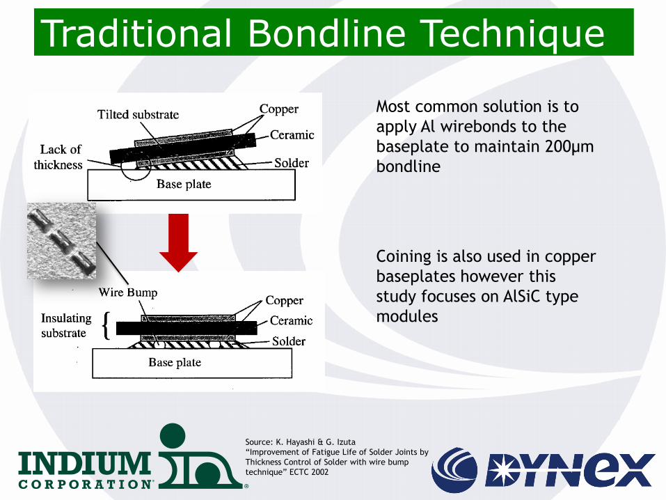
Traditional Bondline Technique
Most common solution is to
apply Al wirebonds to the
baseplate to maintain 200µm
bondline
Coining is also used in copper
baseplates however this
study focuses on AlSiC type
modules
Source: K. Hayashi & G. Izuta
“Improvement of Fatigue Life of Solder Joints by
Thickness Control of Solder with wire bump
technique” ECTC 2002

InForm® Solution
InFORMS® are solder preforms with a braided metal mesh embedded in the solder preform. The mesh-to-solder ratios (height, area, and volume) are designed to maintain the required bondline and promote good solder wetting.
- Solder joint collapse limited to mesh thickness
- Mesh ensures uniform BLT across the entire area vs just 4 corners for wire bond

Novel Bondline Technique
A novel technique to
maintain bondline control is
proposed whereby a metal
mesh is embedded within the
solder preform with no
additional process steps

Test Set Up • Test consisted of assembling six samples of each
variant (no BLC, Al wirebond, metal mesh) – Four of
each variant was tested due to capacity limitations of
the temperature cycling chamber
• 140x70mm AlSiC baseplates (37%Al)
• Cu-AlN-Cu active metal braze ceramic substrates
• 200µm SnSb5 Solder (Variant 1)
• 200µm SnSb5 Solder with 180µm Al wirebond (Variant
2)
• 225µm SnSb5 Solder with 200µm embedded metal
mesh (Variant 3) - InForm

Embedded Metal Mesh
Co-Planarity Variation = 52.5µm
Max Deflection = 60µm
Al Stitch Bond
Co-Planarity Variation = 56.5µm
Max Deflection = 70µm
No BLC
Co-Planarity Variation = 67.5µm
Max Deflection = 90µm
Co-Planarity Variation
After assembly the samples
underwent a laser surface
profiling scan to determine
the height variation across
the substrate
Co-Planarity Variation

Thermal Cycling Samples were thermal cycled
(chamber to chamber) at -50°C
to 150°C (based on actual
customer requirements)
Harsh test conditions
promote creep in ‘hold’
states and allows the samples
to reach thermal equilibrium
resulting in a greater ΔT
when changing temperatures
Samples were to be tested to
failure
Failure is defined as 50%
delaminated area under the
chip

SAM – No BLC vs. InForm®
At 600 cycles, cracks
observed in the samples
without bondline control
between solder and substrate
Samples with embedded
metal mesh shows no
cracking/delamination
No cracking/delamination
seen for Al wire bonds

SAM – Wirebond vs. InForm
Samples with embedded
metal mesh shows no
cracking/delamination
At 800 cycles cracks in the
samples with Al wirebonds
begin to show

SAM – 2000 Cycles
No
Bondline
Control
Typical
Fatigue
InForm
Some
Mesh
Fatigue

SAM – 2000 Cycles
Wirebond
InForm

SEM – 2000 cycles

Presence of the mesh not
only maintains bondline
uniformity but appears to
also acts as a buffer to resist
viscoplastic creep in the joint
*Red lines represent movement of solder during
‘tension’ state
Stress Modeling
Samples with metal mesh
exhibit longer lifetime after
thermal cycling tests
Metal Mesh
Presence of the mesh not
only maintains bondline
uniformity but appears to
also acts as a buffer to resist
viscoplastic creep in the joint

Initial trials began to evaluate the metal mesh preform as a drop in replacement
for the Al wirebond method
Results indicate that the thermal cycling reliability of the metal mesh samples is
superior to traditional bondline control method
Samples with no bond line control show cracking at 600 cycles, samples with Al
wire bonds show cracking at 800 cycles
Theory suggests that the presence of the mesh acts to restrict the viscoplastic
behaviour of the solder during thermal excursions (i.e. the joint becomes more
creep resistant)
Further evaluation (full simulation model and passive cycling tests) is on-going
Samples with metal mesh provide true drop in replacement for bond line control
Summary

Summary
Preform with metal mesh • Increased thermal cycling
reliability – (-50/+150°C) – No failures seen
even at 2000 cycles • No additional process
steps • True drop-in replacement • Wetting and voiding similar
to standard preform
Preform with Al Wire bond •For -50/+150C thermal cycling, cracks seen at 800 cycles Needs additional process steps
Preform with no BLC For -50/+150C thermal cycling, cracks seen at 600 cycles

Indium Corporation

© Indium Corporation
IGBT Module for Aerospace Application •Thermal cycling: -55/+150°C, 1500 passive cycles •Failure defined as delamination > 50% of substrate/baseplate area •200μm-thick desired bondline thickness.
•Sn62/Pb36/2Ag alloy
•Substrate – Al Nitride AMB /Ni
•Base plate – AlSiC - Ni Plated
Aerospace Application
0 TC
No Delam @ 2000 TC
3500 TC - Small delam following mesh
pattern - Module still electrically
functioning

Traction Application
- Soldered Sn/5Sb InForm® - Fluxless Vacuum Process
with Formic Acid - Low Voids <1% - Good Wetting - TC -40/+150C
- 57mm x 49mm; 0.2mm overall thick 0.15mm thick embedded mesh
0 TC 1500 TC

Traction Application – Coplanarity Variation
InForm® vs Wirebond Trim
InForm® Coplanarity variation
Wirebond Trim Coplanarity variation
Less Coplanarity variation with InForm®
More Coplanarity variation with Wirebond Trim

Automotive - HEV Application
© Indium Corporation
Soldered Sn/5Sb InForm® Fluxless Vacuum Process with Formic Acid Low Voiding Good Wetting
Cu(Ni) Base Plate DBC/Ni Substrate InForm® Sn/5Sb 225um InForm® Sn/5Sb 250um 200um Mesh

Automotive - HEV Application Tilt
© Indium Corporation
DBC/Ni Substrate to Cu/Ni base plate: Low thickness variation

Summary

25


