
Embedded control system for smart walking assistance...
20
1534-4320 (c) 2015 IEEE. Personal use is permitted, but republication/redistribution requires IEEE permission. See http://www.ieee.org/publications_standards/publications/rights/index.html for more information. This article has been accepted for publication in a future issue of this journal, but has not been fully edited. Content may change prior to final publication. Citation information: DOI 10.1109/TNSRE.2016.2553369, IEEE Transactions on Neural Systems and Rehabilitation Engineering 1 Embedded control system for smart walking assistance device Matevž Bošnak and Igor Škrjanc, Member, IEEE Abstract—This paper presents the design and implementation of a unique control system for a smart hoist, a therapeutic device that is used in rehabilitation of walking. The control system features a unique human-machine interface that allows the human to intuitively control the system just by moving or rotating its body. The paper contains an overview of the complete system, including the design and implementation of custom sensors, DC servo motor controllers, communication interfaces and embedded-system based central control system. The prototype of the complete system was tested by conducting a 6-runs experiment on 11 subjects and results are showing that the proposed control system interface is indeed intuitive and simple to adopt by the user. Index Terms—walk rehabilitation, walk assistance device, user- intention-based control, control design I. I NTRODUCTION Hoist is a therapeutic device that was developed for the use in rehabilitation of walking after injuries or neural im- pairments. Rehabilitation of walking is a multi-step process that is aimed to return the freedom of motion to the patient. Is is a complex undergoing, mostly based on repetitive tasks execution [1]. It starts with intense therapy of the muscular system and proceeds with the supervised static and dynamic balance train- ing [2]. The dynamic balance training is typically performed in presence of at least two expert therapist who manually assist the subject to walk and maintain the balance at the same time. Several technical solutions have been proposed to relieve the therapists from this physically intensive engagement, such as walking canes, simple static hoists, treadmill-based devices [3], robotic limb manipulators [4], movable support platforms [2] etc. The popularity of the assisted living research topics resulted in presentation of multiple similar devices that were designed for walking assistance to elderly people and those with motor disabilities. Such devices are usually based on a movable platform that is either actively steered [5] or fully motorized and may combine additional features, such as active assistance for standing up and sitting down [6], or even help with other everyday tasks, such as picking up items [7]. Most of these systems are controlled with the use of steerable handle bars or static handles, equipped with force sensors. Since gait and balance instability is one of the most common sources of fall- induced injuries [8], it is essential that the falls are prevented Funded by Slovenian Research Agency. Project number L2-5471, Intelligent robot for walking training. M. Bošnak and I. Škrjanc are with Faculty of Electrical Engineering, University of Ljubljana. during the rehabilitation – systems that can not provide the support for patient’s full body weight during a failure event (loss of balance, tripping, stumbling etc.) are not preferred since constant supervision and presence of the physiotherapist is required. The Hoist device prototype presented in this article provides a fail-safe and patient-engaging approach to gait rehabilitation. The paper is structured as follows. Section II introduces the designed walking assist control system, then a detailed description of the the rehabilitation platform that is built-upon in this research is given in the section III. The description of the base platform, hardware upgrades, embedded system and sensory system is given in separate sub-sections. The paper is concluded with the experimental results in Section IV and a short discussion of the results and the possible upgrades is included in the end. II. WALKING ASSIST CONTROL Our research is focused on functional extension of an existing commercial rehabilitation platform named THERA- Trainer e-go [9], which was designed to offer the support for a strapped-in patient (device user) during the clinical rehabilitation process. Previous work on this platform [2] exposed a potential for a new, intuitive user-machine interface, that will be presented in this paper. The device itself is built as a stable chassis with four caster wheels, equipped with battery power supply, electronics and two additional electrically driven wheels that enable it to move as a two-wheel robot (two of the caster wheels are lifted once driving wheels are attached). The interface between the device chassis and the vertical support frame is made of a ball joint, equipped with adjustable coaxial springs that have limited range of motion in terms of off-vertical deflection angles. The interface enables the user a certain degree of freedom in motion, but it also limits the user’s motion if needed in order to prevent injuries in cases of tripping, stumbling or falling. The idea behind the Hoist project was to augment the manual control mode of the existing walking assist system (illustrated in Fig. ??) by observing the patient and adapting the control strategy accordingly. For this purpose, user po- sition determination and intention-based-control system was designed that allows the patient to control the motion of the device by perturbing its position in regards to the platform base. This approach equates to a very intuitive way of con- trolling the device, since the control system works towards maintaining the neutral position of the user in regards to the platform. The final result is a system that follows the motion
Transcript of Embedded control system for smart walking assistance...

1534-4320 (c) 2015 IEEE. Personal use is permitted, but republication/redistribution requires IEEE permission. See http://www.ieee.org/publications_standards/publications/rights/index.html for more information.
This article has been accepted for publication in a future issue of this journal, but has not been fully edited. Content may change prior to final publication. Citation information: DOI 10.1109/TNSRE.2016.2553369, IEEETransactions on Neural Systems and Rehabilitation Engineering
1
Embedded control system for smart walkingassistance device
Matevž Bošnak and Igor Škrjanc, Member, IEEE
Abstract—This paper presents the design and implementationof a unique control system for a smart hoist, a therapeuticdevice that is used in rehabilitation of walking. The controlsystem features a unique human-machine interface that allowsthe human to intuitively control the system just by movingor rotating its body. The paper contains an overview of thecomplete system, including the design and implementation ofcustom sensors, DC servo motor controllers, communicationinterfaces and embedded-system based central control system.The prototype of the complete system was tested by conductinga 6-runs experiment on 11 subjects and results are showing thatthe proposed control system interface is indeed intuitive andsimple to adopt by the user.
Index Terms—walk rehabilitation, walk assistance device, user-intention-based control, control design
I. INTRODUCTION
Hoist is a therapeutic device that was developed for theuse in rehabilitation of walking after injuries or neural im-pairments. Rehabilitation of walking is a multi-step processthat is aimed to return the freedom of motion to the patient.Is is a complex undergoing, mostly based on repetitive tasksexecution [1].
It starts with intense therapy of the muscular system andproceeds with the supervised static and dynamic balance train-ing [2]. The dynamic balance training is typically performedin presence of at least two expert therapist who manually assistthe subject to walk and maintain the balance at the same time.Several technical solutions have been proposed to relieve thetherapists from this physically intensive engagement, such aswalking canes, simple static hoists, treadmill-based devices[3], robotic limb manipulators [4], movable support platforms[2] etc.
The popularity of the assisted living research topics resultedin presentation of multiple similar devices that were designedfor walking assistance to elderly people and those with motordisabilities. Such devices are usually based on a movableplatform that is either actively steered [5] or fully motorizedand may combine additional features, such as active assistancefor standing up and sitting down [6], or even help with othereveryday tasks, such as picking up items [7]. Most of thesesystems are controlled with the use of steerable handle barsor static handles, equipped with force sensors. Since gait andbalance instability is one of the most common sources of fall-induced injuries [8], it is essential that the falls are prevented
Funded by Slovenian Research Agency. Project number L2-5471, Intelligentrobot for walking training.
M. Bošnak and I. Škrjanc are with Faculty of Electrical Engineering,University of Ljubljana.
during the rehabilitation – systems that can not provide thesupport for patient’s full body weight during a failure event(loss of balance, tripping, stumbling etc.) are not preferredsince constant supervision and presence of the physiotherapistis required. The Hoist device prototype presented in this articleprovides a fail-safe and patient-engaging approach to gaitrehabilitation.
The paper is structured as follows. Section II introducesthe designed walking assist control system, then a detaileddescription of the the rehabilitation platform that is built-uponin this research is given in the section III. The description ofthe base platform, hardware upgrades, embedded system andsensory system is given in separate sub-sections. The paperis concluded with the experimental results in Section IV anda short discussion of the results and the possible upgrades isincluded in the end.
II. WALKING ASSIST CONTROL
Our research is focused on functional extension of anexisting commercial rehabilitation platform named THERA-Trainer e-go [9], which was designed to offer the supportfor a strapped-in patient (device user) during the clinicalrehabilitation process. Previous work on this platform [2]exposed a potential for a new, intuitive user-machine interface,that will be presented in this paper.
The device itself is built as a stable chassis with four casterwheels, equipped with battery power supply, electronics andtwo additional electrically driven wheels that enable it to moveas a two-wheel robot (two of the caster wheels are lifted oncedriving wheels are attached). The interface between the devicechassis and the vertical support frame is made of a ball joint,equipped with adjustable coaxial springs that have limitedrange of motion in terms of off-vertical deflection angles.The interface enables the user a certain degree of freedom inmotion, but it also limits the user’s motion if needed in orderto prevent injuries in cases of tripping, stumbling or falling.
The idea behind the Hoist project was to augment themanual control mode of the existing walking assist system(illustrated in Fig. ??) by observing the patient and adaptingthe control strategy accordingly. For this purpose, user po-sition determination and intention-based-control system wasdesigned that allows the patient to control the motion of thedevice by perturbing its position in regards to the platformbase. This approach equates to a very intuitive way of con-trolling the device, since the control system works towardsmaintaining the neutral position of the user in regards to theplatform. The final result is a system that follows the motion

1534-4320 (c) 2015 IEEE. Personal use is permitted, but republication/redistribution requires IEEE permission. See http://www.ieee.org/publications_standards/publications/rights/index.html for more information.
This article has been accepted for publication in a future issue of this journal, but has not been fully edited. Content may change prior to final publication. Citation information: DOI 10.1109/TNSRE.2016.2553369, IEEETransactions on Neural Systems and Rehabilitation Engineering
2
of the user, while providing a constant fail-safe support forthe user.
A. User position determination
User’s position in regards to the platform is determined byobserving the angles between the left/right (vertical) struts andthe base frame (illustrated in Fig. ??). For this purpose, strutsand frame are equipped with bespoke tilt sensors (detailedin chapter III-C), allowing the relative angles between theframe and struts to be determined. The x-axis of the platformframe coordinate system is oriented towards the front of thedevice (towards the control unit in Fig. ??) and the z-axisis oriented vertically in the up direction, while the y-axis isoriented towards the left side of the frame, creating a right-handed Cartesian coordinate system.
While at rest, the tilt sensor coordinate system axes arealigned with the platform frame coordinate system. Deflectionangles of the vertical support struts are mechanically limited toapproximately 15 from the vertical direction and the angularvelocities of the struts are relatively low due to the long lengthof the struts. By using the small angle approximation of thetrigonometric functions, rotation transformations between theplatform frame coordinate system to tilt sensor coordinatesystem can be handled individually for the rotations aroundthe x and y axes. Let α denote the angle of rotation aroundthe sensor’s y axis that rotates the platform frame coordinatesystem to a tilt sensor coordinate system and β denote theangle of rotation around the sensor’s x axis that rotates theplatform frame coordinate system to a tilt sensor coordinatesystem.
Perturbations of the the user harness attachment point origin(∆x,∆y) and orientation ∆ψ is therefore calculated using thefollowing equations
∆x =d(tanαl + tanαr)
2, (1)
∆y = −d(tanβl + tanβr)
2, (2)
∆ψ = arctand(tanαr − tanαl)
2ds(3)
where d is the vertical distance between the elastic joints andhorizontal user support strut, ds is the length of that strut(i.e. horizontal distance between the two vertical struts), whileαl, βl, αr and βr are α and β angles for the left and rightstrut, respectively. Since the deflection angle of the struts islimited, the above equations can be simplified by replacingthe tan functions with the linear small-angle approximation,which results in ∆x ≈ d(αl+αr)
2 , ∆y ≈ −d(βl+βr)2 and ∆ψ ≈d(αr−αl)
2ds.
These perturbations are used for estimating the position ofthe user in regards to the platform, which directly indicatesthe intention of the user for motion. This is justified by thefollowing assumptions:• When the user intends to move in the forward direction,
the user will initiate a move in that direction, causingits relative position in regards to the platform to moveforward.
• When the user intends to speed up or slow down, user’sspeed will increase or decrease, respectively. This directlyresults in relative position of the user in regards to theplatform to change to more forward (user is accelerating)or more backwards (user is slowing down) position.
• When the user intends to change the direction of motion,the user will rotate his/her pelvis in that direction [10].
Based on these assumptions, the values of ∆x and ∆ψ canbe used directly as an estimation of user intent for accelerationand turning, while the side motion ∆y can be used as ameasurement of the user’s walking (gait) quality [2], [11].
B. Control algorithm
The control system must be robust enough to ignore normaloscillations in the signals that result from walking dynamics,however special care must be taken for allowing the userto execute controlled rapid stopping manoeuvres. Thus, thecontroller combines a regular P-controller and a filtered P-controller (PfP controller), a combination that allows the userto have the feeling of an immediate control (regular P part) andsmooth changes in the average speed of the platform (filtered Ppart, that simulates the effect of an integrator. Such controllerhas a continuous transfer function of H(s) = KP +KP,f (τs+1)−1. Input dead-band with variable width was added to thecontroller to tackle the problem of measurement (input) noisein vicinity of the user’s neutral position and allow the user tokeep the platform stationary when needed. Motion directionreversal situation is also handled separately, improving thedeceleration during braking action.
The continuous transfer function of the controller has beendiscretized by zero-order hold method using the step time of∆T = 10ms and the resulting difference equation can bewritten as
vk = KP · uk + vf,k (4)
vf,k = Kf,1 · vf,k−1 +Kf,2 · (KP,f · uk), (5)
where Kf,1 = e−∆Tτf . The time constant of the filter τf is
defined as follows
τf =
τdec, |uk| ≤ Dx
∆T Ldec|uk|−Dx , |uk| > Dx, uk · vk−1 < 0
τn, |uk| > Dx, uk · vk−1 ≥ 0
(6)
and Kf,2 is defined as
Kf,2 =
0, |uk| ≤ Dx
K2,r, |uk| > Dx, uk · vk−1 < 0
(1− e−∆Tτn ), |uk| > Dx, uk · vk−1 ≥ 0
(7)
The three cases above define the parameters in three operatingmodes of the controller: dead-band operation (uk ≤ Dx), mo-tion reversal or braking operation (uk > Dx and uk ·vk−1 < 0)and normal operation (uk > Dx and uk · vk−1 ≥ 0).
In dead-band operation, input value is discarded (hence Kf,2
is set to 0), while the time constant of the filtered part τf isset to a fixed value of τdec. The motion direction reversal(i.e. braking) operation must allow the user to rapidly stop themotion of the platform, which is realized by cancelling the

1534-4320 (c) 2015 IEEE. Personal use is permitted, but republication/redistribution requires IEEE permission. See http://www.ieee.org/publications_standards/publications/rights/index.html for more information.
This article has been accepted for publication in a future issue of this journal, but has not been fully edited. Content may change prior to final publication. Citation information: DOI 10.1109/TNSRE.2016.2553369, IEEETransactions on Neural Systems and Rehabilitation Engineering
3
slow response rate of the implemented low-pass filter. Timeconstant of the filter τf in this operation mode is thereforedependent on the value of the input uk and parameters Dx
and Ldec (Fig. ??), that define the dead-band width andtime constant function shape, respectively. Since the controlleroperates in this mode only outside the dead-band, a fixed valueof τdec is used for the time constant inside it.
The parameter K2,r is selected to have a relatively low value(0 < K2,r (1− e−
∆Tτn )) to obtain the deceleration towards
the standstill position, while its value has to be greater thanzero in order for the motion direction to truly reverse – withoutit, the condition for normal operation uk · vk−1 ≥ 0 wouldnever be met after initiating a direction reversal manoeuvre.
Although the choice of controller parameters greatly de-pends on the walking ability of the current user (mostly dead-band Dx, gains KP , KP,f , the shape of braking curve Ldecand maximum value of the filtered part vf,max), generic set ofvalues for the parameters has been determined in experimentalruns. By using these values, test subjects were able to controlthe speed of the platform in precise and smooth way, asdemonstrated in the experimental study (Section IV).
Algorithm 1 Translational motion controller
1: procedure TRANSPI(uk , v, vf )2: if |uk| < Dx then3: vf ← e
− ∆Tτdec · vf
4: v ← vf5: else6: u′k ← uk ·KP,f
7: if uk · v < 0 then8: vf ← e
−|uk|−DxLdec · vf +K2,r · u′k9: else
10: vf ← e−∆Tτn · vf + (1− e−
∆Tτn ) · u′k
11: vf ← limitvf , [−vf,max, vf,max]12: v ← KP · uk + vf
The implemented algorithm is listed as Algorithm 1 (trans-lational motion controller), where the following variables areused:uk The input variable – normalized perturbation of the user’s
position in forwards-backwards direction (values in range[−1,0; 1,0])
v The output variable that controls the reference speed forthe servo motors, driving the wheels
vf The filtered part of the output variablevf,max The maximum value of the filtered part of the output vari-
able that determines the maximum accumulated velocityDx Dead-band of the input variable (5% of the uk range)τn Time constant of the filter in normal operation (τn = 10
s)τdec Time constant of the filter in dead-band operation (τdec =
2 s)Ldec Parameter that determines the gain of the exponential
braking function (Ldec = 2,0)K2,r See description in text (K2,r = 0,0001)KP Proportional gain of the normal part of the controller
(KP = 2,0)
KP,f Proportional gain of the filtered part of the controller(KP,f = 50,0)
Similar controller was designed for rotational motion. It isalso based on the PfP concept without the direction reversallogic. The implementation of the algorithm is given below.
Algorithm 2 Rotational motion controller
1: procedure ROTPI(uψ,k , ω, ωf )2: if |uψ,k| < Dψ then3: ωf ← e
− ∆Tτψ,dec · ωf
4: else5: u′ψ,k ← Kψ,P,f · uψ,k6: ωf ← e
− ∆Tτψ,n · ωf + (1− e−
∆Tτψ,n ) · u′ψ,k
7: ω ← Kψ,P · uψ,k + ωf
The following variables are used in algorithm 2 (rotationalmotion controller):uψ,k The input variable – normalized perturbation of the user’s
pelvis orientation (values in range [−1,0; 1,0])ω The output variable that controls the reference rotational
velocity for the servo motors, driving the wheelsωf The value (state) of the filtered part of the controllerDψ Dead-band of the input variable (5% of the ∆ψ range)τψ,n Time constant of the filter in normal operation (τψ,n = 2
s)τψ,dec Time constant of the filter in dead-band operation
(τψ,dec = 0,1 s)Kψ,P Proportional gain of the normal part of the controller
(Kψ,P = 2,0)Kψ,P,f Proportional gain of the filtered part of the controller
(Kψ,P,f = 50,0)
III. DESCRIPTION OF THE REHABILITATION PLATFORMHoist
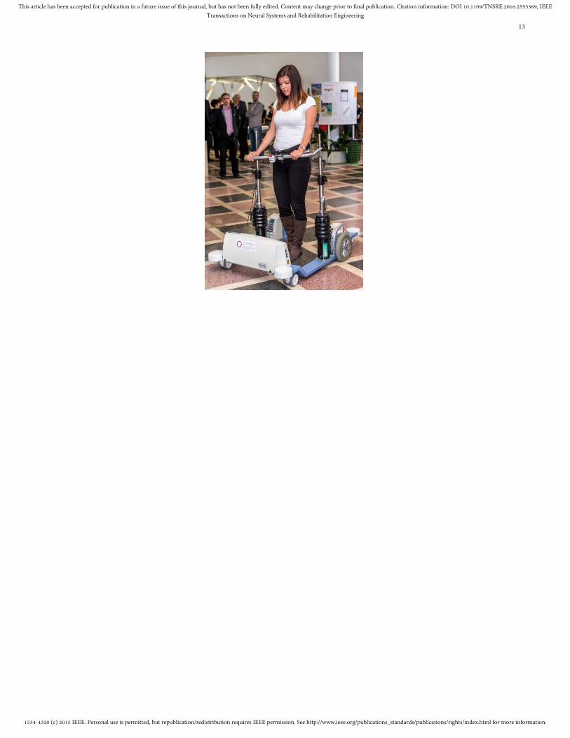
As noted in the previous section, modified commercialrehabilitation device THERA-Trainer e-go [9] is used as theplatform in this research. The original device has been mod-ified by replacing all electronics with bespoke components.The device has been equipped with multiple sensors thatobserve the device’s and user’s motion and position. Forthe purpose of odometry based position determination, eachdriven wheel has been equipped with a rotational encoder thatmeasures speed and position of each wheel. In addition, threeMEMS (Micro-Electro-Mechanical) angular rate and linearacceleration sensors are used to measure the chassis and user’ssupport struts orientation (Fig. ?? shows the device duringdemonstration and testing). The data collection, processing andcontrol is done on a Odroid XU3 embedded system, runningUbuntu linux distribution. The embedded system runs ROS(Robot Operating System) on top of Ubuntu operating system,with ROS taking care of inter-device communication tasks,data gathering, data processing synchronization etc.
A. Electrical and drive system
Main power supply consists of two 12 V, 18 Ah lead-acid batteries that power the motor drivers via an emergency

1534-4320 (c) 2015 IEEE. Personal use is permitted, but republication/redistribution requires IEEE permission. See http://www.ieee.org/publications_standards/publications/rights/index.html for more information.
This article has been accepted for publication in a future issue of this journal, but has not been fully edited. Content may change prior to final publication. Citation information: DOI 10.1109/TNSRE.2016.2553369, IEEETransactions on Neural Systems and Rehabilitation Engineering
4
cut-off relay, the embedded computer via a 5 V switchingpower supply and CAN (Controller Area Network) devicesvia separate 12 V switching power supply.
The propulsion system basically mimics a two-wheeledrobot with a differential drive. Each driven wheel has itsown 100 W geared electric motor with a shaft encoder anda dedicated speed controller that is attached to the sharedCAN bus on the device. Each motor driver executes a closed-loop speed control algorithm with adjustable current limits.Motor parameters (e.g. position, speed, motor current, etc.)are adjustable and observable using the CAN bus protocol.
B. CAN communication bus
CAN is a broadcasting digital bus designed to operateat preselected speeds from 20 kbit/s to 1 Mbit/s with thetransmission rate selected depending on the bus length, to-pography and transceiver capabilities. CAN is an attractivesolution for embedded control systems because of its low cost,light protocol management, the deterministic resolution of thecontention, and the built-in features for error detection andretransmission [12].
CAN has a proven reliability in automotive and processindustry [13], [14] and was therefore a preferred option for anetwork between different low-level subsystems in the Hoistsystem. A relatively conservative bus speed of 250 kbit/s waschosen for the CAN bus in this project (illustrated in Fig.??) that has a total length of 4 m with two 1 m long stubs(unterminated bus ends). Split-type bus termination was usedon left and right motor driver CAN nodes, as suggested in[15].
A simple bi-directional gateway between CAN bus andUART (Universal Asynchronous Receiver/Transmitter) wasdesigned in order to simplify the access to the CAN bus fromthe high-level control system, which lacks support for CANbus communication.
C. Tilt sensors
The device is equipped with three tilt sensors, two of whichare mounted on the vertical support struts and one mounted onthe base (platform chassis). This sensor arrangement providesa simple method of measuring the relative orientation betweenthe support frame struts and the base. Since the motion in eachaxis is restricted mechanically to approximately ±15 degreesfrom vertical and corresponding angular velocities are low, tiltangles are calculated independently for each axis (producingangles α and β, as indicated in Fig. ??). Since the supportstruts are mechanically restricted from rotating around thethird (vertical) axis, estimation of the third orientation angleis not required for this application.
The custom built tilt sensors host power supply system, mi-crocontroller and MEMS-based gyroscope and accelerometer.As gyroscope output (angular rate) is biased and has to beintegrated over time to obtain the orientation angle, dual sim-plified one-axis sensor fusion algorithms were implementedin the microcontroller of each tilt sensor, resulting in twoindependent orientation angle estimates per sensor (angles αand β).
The fusion algorithm for one axis is based on static Kalmanfilter. If the following states are selected for the state vectorxk
xk =[φk φb,k θk θb,k
]T(8)
where φk, θk are the values of the angles φ, θ at the momentk, φb,k, θb,k are gyroscope output biases at the moment k andinput vector uk contains current angular rates measurement
uk =[φm,k θm,k
]T(9)
the system is presented in the following state space form
xk = Axk−1 + Buk (10)
yk = Cxk =
[1 0 0 00 0 1 0
]xk (11)
A =
1 −∆t 0 00 1 0 00 0 1 −∆t0 0 0 1
B =
∆t 00 00 ∆t0 0
(12)
Kalman filter can be evaluated offline because of the fixedstate-transition, input and output matrices along with fixedstate and measurement noise covariance matrices (V and N,respectively). In order to obtain static Kalman filter gain matrixKs, the following steps are evaluated iteratively until theKk converges to Ks (a posteriori covariance matrix Pk isinitialized before starting the iteration):
1) P∗k = APk−1AT + V,
2) Kk = P∗kCT [CP∗kC
T + N]−1,3) Pk = P∗k −KkCP∗k.
Based on the approximate values of the signal variances andsome manual fine-tuning, the following values were used inour implementation:
∆t = 0.01s P0 = I
V = diag(0.1 rad2, 1 rad2/s2, 0.1 rad2, 1 rad2/s2) (13)
N = diag(800 rad2, 800 rad2)
which resulted in the following static Kalman gain Ks
Ks =
[0.0102 −0.0013 0 0
0 0 0.0102 −0.0013
]T(14)
The notation diag(λ) was used to denote a diagonal matrixwith the elements of vector λ on the diagonal. Static Kalmanfilter was then implemented in the microcontroller in theiterative form with time step of ∆t = 0.01 s, consisting ofthe prediction step
xk = Ax∗k−1 + Buk−1 (15)
and the correction step
x∗k = xk +Ks
([φs,k θs,k
]T −Cxk
)(16)
where the current sensor angles φs,k and θs,k were calculatedfrom the acceleration measurements ax,k, ay,k and az,k
φs,k = arctan−az,kay,k
(17)
θs,k = arctan−az,kax,k
(18)

1534-4320 (c) 2015 IEEE. Personal use is permitted, but republication/redistribution requires IEEE permission. See http://www.ieee.org/publications_standards/publications/rights/index.html for more information.
This article has been accepted for publication in a future issue of this journal, but has not been fully edited. Content may change prior to final publication. Citation information: DOI 10.1109/TNSRE.2016.2553369, IEEETransactions on Neural Systems and Rehabilitation Engineering
5
D. Servo drives
Original motor drivers for the 40 V, 100 W geared electricmotors with built-in shaft encoders were embedded into thecontrol box hardware in front of the platform. Since therewas no external interface available to control them, variouscommercial compact servo motor controllers were initiallyevaluated for this application, but most failed to work properlyat low operating speeds. Therefore, a custom servo motorcontroller was designed, which operates appropriately at lowrotational speeds and also fits into the tight space in thedrivetrain housing itself (Fig. ??).
The application running on the servo controller allows theaccess to all controller parameters, current position, speed andmotor current via CAN bus messages.
1) Electronics design: The servo controller is built aroundCortex-M0 microcontroller with an integrated CAN transceiverand smart H-bridge MOSFET (Metal–Oxide–SemiconductorField-Effect Transistor) driver with external power MOSFETH-bridge. Since the microcontroller has the CAN bus function-ality built-in, the driver is directly accessible from the controlsystem for configuration and control. The physical dimensionsof the designed servo controller allow the board to be mounteddirectly onto the gearbox, which also acts as a heatsink for thedriver’s PCB (Printed Circuit Board).
2) Servo control loop: The servo control loop is shownon Fig. ??. It is a semi-cascaded controller with currentlimit in internal loop and velocity-mode PI servo controllerin external loop. Current shaft rotational velocity is obtainedby differentiating the shaft position and filtering the resultusing a first order low-pass filter. The reference speed as theinput variable is rate-limited to limit the maximum motoracceleration in order to reduce the mechanical stress of thecomponents and limit the electric current spikes. There is anadditional feedback loop from current limit controller back tointegral of the PI controller to avoid saturation effects. Theservo control loop is executed at a fixed frequency of 1 kHz.
E. Embedded system
Initially a compact embedded system BeagleBone Blackwas selected as the main computational platform for theproject, but was later replaced by a more capable OdroidXU3 embedded system. Additionally, a small wireless routerwas used to provide a reliable WiFi connection betweenthe Hoist system and the external monitoring and controlcomputers. To interface the CAN bus devices, a USB-UARTconverter was used to talk to our custom UART-CAN gateway.Battery voltages, bumper switches and other configurationswitches were connected to a PoKeys57U USB device, whichis interfaced by the embedded computer with the help of across-platform open-source communication library PoKeysLib[16].
We used Ubuntu 14.04 LTS as the operating system of theembedded computer with meta-operating system ROS (RobotOperating System) version Indigo. ROS (Robot OperatingSystem) is a meta-operating system, containing libraries andtools to help software developers create robot applications.It provides hardware abstraction, device drivers, libraries,
visualizers, message-passing, package management and more(details are available in online ROS documentation [17]).
Our application was divided into a set of ROS nodes that canbe started individually and used on different hosts as long asall the hosts are configured with the same ROS environmentand network settings. Main ROS node was designed as aninterface between ROS system and the physical hoist device.It uses CAN bus communication (using the CAN gateway) tocommunicate with servo motor drivers and tilt sensors, usesanalog inputs of the PoKeys57U device to monitor the batteryvoltage and digital inputs to monitor the state of bumperswitches. Motion commands are forwarded to wheel motordrivers, while wheel odometry data is generated from thereported encoder positions and exported along with sensorreading and switch statuses to ROS environment in the formof standard ROS message types.
F. Environment sensing
Three parts of the primary hoist system are used to sense thephysical environment - wheels odometry information, bumperswitch sensors and platform tilt sensor.
Each driven wheel of the hoist is equipped with an encoder,whose position is constantly tracked by the servo drive (for thepurpose of closed-loop speed control and position tracking)and broadcasted over CAN bus. The main ROS node receivesboth left ∆EL,k and right ∆ER,k wheel encoder informationfrom servo drives and combines this information into odometrydata. The following equations are evaluated periodically forevery step k
∆dk =∆EL,k + ∆ER,k
2Kp→m, (19)
∆φk =∆ER,k −∆EL,k
dwwKp→m, (20)
px,k+1 = px,k + ∆dk cos pφ,k, (21)
py,k+1 = py,k + ∆dk sin pφ,k, (22)
pφ,k+1 = pφ,k + ∆φk, (23)
where Kp→m is a factor that translates the encoder changeto driven wheel distance, dww is the distance between thedriven wheels, while px,k, py,k and pφ,k are components ofthe position state vector, describing positions in axes x, y androtation around vertical axis φ, respectively.
IV. RESULTS
The platform and proposed control system approach weretested both in simulated environment (using ROS and Gazebowith a mathematical and visual model of the platform) and inexperimental study in laboratory environment, mainly testingthe turning control of the platform. The experimental resultswill be presented next.

1534-4320 (c) 2015 IEEE. Personal use is permitted, but republication/redistribution requires IEEE permission. See http://www.ieee.org/publications_standards/publications/rights/index.html for more information.
This article has been accepted for publication in a future issue of this journal, but has not been fully edited. Content may change prior to final publication. Citation information: DOI 10.1109/TNSRE.2016.2553369, IEEETransactions on Neural Systems and Rehabilitation Engineering
6
A. Experimental results
Because the presented device is a prototype, the experimentwas limited to 11 healthy subjects in 6 different runs (seeTable I) in the confined space of about 5 by 5 meters. Thesubjects were 10 male and 1 female volunteers (aged between25 and 65), who had none or very limited experience with thepresented device.
The experiment was executed in two stages, as it is imaginedthe device to be used in true rehabilitation sessions. First,the remote control functionality of the presented system wasemployed, where operator of the device forced the subject tofollow the hoist in the prescribed pattern, drawn on the floor.During this first step, the subjects were only told to followthe motion of the platform. In the second stage, the subjectswere instructed to control the system by following the samepattern. Each run consisted of at least two executions of theprescribed pattern.
Two patterns were used for trajectory shape during experi-ments (Fig. ??), while only the figure of eight pattern (denotedas ∞) was used for autonomous operation by the subject.The experimental runs 1 (square pattern ) and 2 (figure ofeight pattern ∞) were first conducted (system controlled bythe operator using remote control), then experimental run 3(pattern ∞) followed, where the subject had full control ofthe system.
In the runs 4, 5 and 6, the subjects were equipped withleg-mounted contraption that simulated an injury to the leg’smuscles or nerve system [18], which allowed us to evaluate thesuitability of the proposed control system for the real patientsin the clinical rehabilitation process. Since some subjectsrejected installing the orthosis, there is some missing data(denoted by −).
For the purpose of results evaluation, all sensor measure-ments were recorded on-board the presented experimentalsystem. This includes calibrated odometry data for evaluationof the tracking quality, remote control commands and sensorydata, that was used for the user position assessment and user-input based control of the system.
The results were evaluated both in terms of executionprecision of the reference trajectory shape and in terms ofcross-correlation between the ∆ψ (obtained from struts tiltangles) and rotational velocity around the vertical axis Ωr ofthe reference trajectory.
Before executing the cross-correlation, the data sequenceswere normalized so that the autocorrelations at zero lag equal1 (MATLAB’s function xcorr). The results are gathered inTable II.
The execution precision of the reference trajectory shapewas evaluated using the normalized ISE (integral square error)cost function JN of the pose error, defined as a differencebetween the actual (xi, yi, ψi) and reference pose samples(xr,i, yr,i, ψr,i), consisting of both the position and the ori-entation parts
JN =1
L
N∑i=1
((xi − xr,i)2 + (yi − yr,i)2
)+
1
L
N∑i=1
(ψi−ψr,i)2
(24)
The normalization value L is the total length of the referencepath, calculated from the odometry data. Values of cost func-tions for all runs are gathered in Table III.
Except for runs 1 and 4 (with a square shaped referencetrajectory), in average results show a good correlation betweenthe user’s pelvis rotation angle ∆ψ and reference rotationalvelocity Ωr. The most surprising are the correlation resultsof run 2, where subjects were being externally commanded(using a remote control feature) and were following the figureof eight pattern for the first time. Although they were toldonly to follow the motion induced by the machine, the resultsshow that they were indicating the change of the direction bythe additional rotation of the pelvis into the direction of theturn. This fact strengthens the idea of the proposed systembeing indeed very intuitive to use. By comparing the resultsbetween the runs 2 and 5, latter being executed after runs 1to 4, it is generally true that the indicative pelvis motion hasbeen amplified after just a few experimental runs (taking 1 to2 minutes each), additionally confirming the intuitive learningnature of the presented control system.
An interesting view on this matter can be given by observingthe values of the cost function that was used to estimatethe execution precision of the reference trajectory shape. Theresults (both numerically in Table III and graphically in Fig.?? and ??) show that subjects in control of the system weresuperior to external remote control in following the prescribedcurve with and without injury simulation, resulting in lowervalue of the cost function in runs 3 and 6. Fig. ?? and?? illustrate the results for subjects 3, 4 and 5 in runs 2,3, 5 and 6 by overlaying odometry-based trajectories of theplatform (solid line) over the reference trajectory (dotted line)with arrows illustrating the intended turning direction andamplitude, as estimated from the user intent of turning (chapterII-A).
The results for subject 5 show greater cost values andhence worse execution precision of the reference trajectoryshape, which is the result of subject overpowering the machine,causing the systems drive wheels to slip and loose the correctodometry data.
No subject had problems with commanding the translationalvelocity of the platform, easily adapting it to the user’s needsor abilities.
V. CONCLUSION
The prototype of walk rehabilitation system with the imple-mentation of the presented control system has been provenin experimental study for being very intuitive and easy toadopt by the users. Most indicative are the experimental runsexecuted in External control mode (remote control by theoperator), which produced data, that clearly show a positivecorrelation between the user’s intention (pelvic rotation) andthe rotational velocity along the prescribed reference trajec-tory. The subjects were only instructed to follow the motion ofthe platform along the trajectory and since the pelvic rotationclearly exceeded the platform’s orientation changes along thepath, we assume that the presented approach to the predictionof the user’s intention is valid and allows natural (intuitive)

1534-4320 (c) 2015 IEEE. Personal use is permitted, but republication/redistribution requires IEEE permission. See http://www.ieee.org/publications_standards/publications/rights/index.html for more information.
This article has been accepted for publication in a future issue of this journal, but has not been fully edited. Content may change prior to final publication. Citation information: DOI 10.1109/TNSRE.2016.2553369, IEEETransactions on Neural Systems and Rehabilitation Engineering
7
motion control of the platform. Precision of the referencetrajectory shape execution improved by a large margin whenthe control was handed over to the subjects themselves,indicating their ability of precise control over the motion of thesystem. Interestingly, although leg injury simulation was usedin run 6, results generally improved over those from run 3.This can be explained by additional experience gained duringruns 4 and 5 and system’s ability to cope with stray inputsignals, originating from the injury-induced changes in theirwalking patterns.
Based on the encouraging experimental test results onhealthy subjects, the proposed control system will be evaluatedon subjects with reduced motor and/or cognitive abilities,where similar results are expected. This will enable us tofurther check the validity of the above claims and adequacyof the default control system parameters (Section II-B) for alarger set of users.
REFERENCES
[1] M. G. Bowden, A. E. Embry, L. A. Perry, and P. W. Duncan, “Rehabili-tation of walking after stroke,” Current Treatment Options in Neurology,vol. 14, no. 6, pp. 521–530, 2012.
[2] A. Olenšek, J. Oblak, I. Cikajlo, P. Novak, K. Jere, and Z. Matjacic,“Adaptive dynamic balance training during overground walking withassistive device,” Proceedings of the IEEE RAS and EMBS InternationalConference on Biomedical Robotics and Biomechatronics, pp. 1066–1070, 2012.
[3] X. Zhang, X. Kong, G. Liu, and Y. Wang, “Research on the walkinggait coordinations of the lower limb rehabilitation robot,” in 2010 IEEEInternational Conference on Robotics and Biomimetics, ROBIO 2010,2010, pp. 1233–1237.
[4] J. F. Veneman, R. Kruidhof, E. E. G. Hekman, R. Ekkelenkamp, E. H. F.Van Asseldonk, and H. Van Der Kooij, “Design and evaluation ofthe LOPES exoskeleton robot for interactive gait rehabilitation,” IEEETransactions on Neural Systems and Rehabilitation Engineering, vol. 15,no. 1, pp. 379–386, 2007.
[5] A. J. Rentschler, R. Simpson, R. A. Cooper, and M. L. Boninger,“Clinical evaluation of Guido robotic walker.” Journal of rehabilitationresearch and development, vol. 45, no. 9, pp. 1281–1293, 2008.
[6] D. Chugo, T. Asawa, T. Kitamura, J. Songmin, and K. Takase, “Amotion control of a robotic walker for continuous assistance duringstanding, walking and seating operation,” 2009 IEEE/RSJ InternationalConference on Intelligent Robots and Systems, IROS 2009, pp. 4487–4492, 2009.
[7] B. Graf, M. Hans, and R. D. Schraft, “Care-O-bot II - Development of aNext Generation Robotic Home Assistant,” Autonomous Robots, vol. 16,no. 2, pp. 193–205, 2004.
[8] B. T. Tyson, M. T. Pham, N. T. Brown, and T. R. Mayer, “Patient SafetyConsiderations in the Rehabilitation of the Individual with CognitiveImpairment,” Physical Medicine and Rehabilitation Clinics of NorthAmerica, vol. 23, no. 2, pp. 315–334, may 2012. [Online]. Available:http://linkinghub.elsevier.com/retrieve/pii/S1047965112000150
[9] medica, “THERA-Trainer e-go (http://www.thera-trainer.de/english/professional/gait/thera-trainer-e-go/index.html),”2015. [Online]. Available: http://www.thera-trainer.de/english/professional/gait/thera-trainer-e-go/index.html
[10] Z. Matjacic and A. Olenšek, “Apparatus for training dynamic balanceand turning manoeuvres during walking, Pat.Nr. WO2014081400,” 2014.
[11] I. Cikajlo, J. Oblak, and Z. Matjacic, “Haptic floor for virtual balancetraining,” 2011 IEEE World Haptics Conference, WHC 2011, pp. 179–184, 2011.
[12] M. Di Natale, H. Zeng, P. Giusto, and A. Ghosal, Understanding andUsing the Controller Area Network Communication Protocol. SpringerNew York, 2012.
[13] G. I. Mary, Z. C. Alex, and L. Jenkins, “Reliability Analysis ofController Area Network Based Systems — A Review,” InternationalJournal of Communications, Network and System Sciences, vol. 6, pp.155–166, 2013.
[14] K. H. Johansson, M. Törngren, and L. Nielsen, “Vehicle Applicationsof Controller Area Network,” Handbook of Networked and EmbeddedControl Systems, vol. VI, pp. 741–765, 2005. [Online]. Available:http://www.springerlink.com/index/nr49ql1152p5m211.pdf
[15] S. Corrigan, “Controller Area Network Physical Layer Requirements,”Texas Instruments, Tech. Rep. SLLA270, 2008.
[16] PoLabs, “PoKeys library PoKeysLib,” 2015. [Online]. Available:http://blog.poscope.com/pokeyslib-pokeys-library/
[17] ROS, “Documentation - ROS Wiki (http://wiki.ros.org/).” [Online].Available: http://wiki.ros.org/
[18] A. Olenšek, Z. Matjacic, and T. Bajd, “Muscle contracture emulatingsystem for studying artificially induced pathological gait in intactindividuals,” Journal of Applied Biomechanics, vol. 21, no. 4, pp. 348–358, 2005.

1534-4320 (c) 2015 IEEE. Personal use is permitted, but republication/redistribution requires IEEE permission. See http://www.ieee.org/publications_standards/publications/rights/index.html for more information.
This article has been accepted for publication in a future issue of this journal, but has not been fully edited. Content may change prior to final publication. Citation information: DOI 10.1109/TNSRE.2016.2553369, IEEETransactions on Neural Systems and Rehabilitation Engineering
8
Run1 2 3* 4 5 6*
Trajectoryshape ∞ ∞ ∞ ∞
Control bysubject X X
Injurysimulation X X X
TABLE I: Experimental runs (* platform was controlled by the subject)
Run1 2 3* 4 5 6*
1 0,09 0,60 0,95 - - -2 -0,05 0,23 0,91 - - -3 0,05 0,42 0,86 0,11 0,47 0,924 0,15 0,76 0,91 0,10 0,88 0,915 0,06 0,49 0,77 0,10 0,65 0,816 0,01 0,18 0,70 0,14 0,69 0,927 0,09 0,39 0,89 0,11 0,45 0,878 0,05 0,24 0,91 - - -9 0,10 0,70 0,86 - - -
10 0,12 0,35 0,86 0,12 0,51 0,9311 0,12 0,56 0,95 0,11 0,77 0,91
C 0,07 0,45 0,87 0,11 0,63 0,90
TABLE II: Values of the cross-correlation factor for all experimental runs at zero lag with the average value C for all subjectsper each run in the last row – higher value is better (* platform was controlled by the subject)
Run1 2 3* 4 5 6*
1 30,35 9,42 3,78 - - -2 32,38 8,41 5,88 - - -3 30,57 29,73 3,56 30,92 5,58 2,124 36,93 4,06 3,41 110,63 11,12 3,615 50,06 6,80 17,80 31,17 13,30 9,876 29,83 3,58 7,05 72,55 3,63 7,797 30,34 5,01 7,29 32,15 12,39 4,438 10,64 6,84 5,05 - - -9 31,79 24,76 4,78 - - -10 34,96 14,36 6,62 40,52 31,22 7,4011 74,01 12,20 8,68 78,78 8,58 7,72
J 35,62 11,38 6,72 56,67 12,26 6,13
TABLE III: Values of normalized ISE cost function JN for all experimental runs with the average value J for all subjects pereach run in the last row – lower value is better (* platform was controlled by the subject)

1534-4320 (c) 2015 IEEE. Personal use is permitted, but republication/redistribution requires IEEE permission. See http://www.ieee.org/publications_standards/publications/rights/index.html for more information.
This article has been accepted for publication in a future issue of this journal, but has not been fully edited. Content may change prior to final publication. Citation information: DOI 10.1109/TNSRE.2016.2553369, IEEETransactions on Neural Systems and Rehabilitation Engineering
9
List of figures (figure’s page number, suggested width in text, color options, LaTeX figure ID) with captions:(page 10, suggested width: 8cm, printed in B/W) figure:hoist_system
Fig. 1: Parts of the Hoist system(page 11, suggested width: 7cm, printed in B/W) figure:hoist_system_angles
Fig. 2: Illustration of the Hoist platform(page 12, suggested width: 8cm, printed in B/W) figure:hoist_exp_brake
Fig. 3: Exponential braking (|uk| > Dx and uk · vk−1 < 0) - decay time constant at Dx = 0,05 (shaded area) and Ldecvarying from 2,0 to 50
(page 13, suggested width: 6cm, printed in B/W) figure:jasnaFig. 4: The Hoist system demonstration and testing
(page 14, suggested width: 6cm, printed in B/W) figure:CAN_networkFig. 5: CAN network on Hoist
(page 15, suggested width: 8cm, printed in B/W) figure:CAN_driverFig. 6: Servo drive circuit fitted directly to the gearbox
(page 16, suggested width: 9.5cm, printed in B/W) figure:servo_loopFig. 7: Servo control loop
(page 17, suggested width: 6cm, printed in B/W) figure:exp_shapesFig. 8: Trajectory shapes used in the experiments
(pages 18-19) One figure with two sub-figures 9a and 9b on the same pageFig. 9: Experimental results of runs
(page 18, suggested width: 14cm, printed in B/W) figure:exp_resultsExtFig. 9a: external (therapist) control without (first row) and with injury simulation (second row)
(page 19, suggested width: 14cm, printed in B/W) figure:exp_resultsSubjFig. 9b: subject (user) control without (first row) and with injury simulation (second row)

1534-4320 (c) 2015 IEEE. Personal use is permitted, but republication/redistribution requires IEEE permission. See http://www.ieee.org/publications_standards/publications/rights/index.html for more information.
This article has been accepted for publication in a future issue of this journal, but has not been fully edited. Content may change prior to final publication. Citation information: DOI 10.1109/TNSRE.2016.2553369, IEEETransactions on Neural Systems and Rehabilitation Engineering
10
right strut
user
support
drive
control
caster wheels frame
left strut
elastic joints
harness
units
unit

1534-4320 (c) 2015 IEEE. Personal use is permitted, but republication/redistribution requires IEEE permission. See http://www.ieee.org/publications_standards/publications/rights/index.html for more information.
This article has been accepted for publication in a future issue of this journal, but has not been fully edited. Content may change prior to final publication. Citation information: DOI 10.1109/TNSRE.2016.2553369, IEEETransactions on Neural Systems and Rehabilitation Engineering
11
αl
Left strutRight strut
x y
zβl
xy
z
d
ds
Frame

1534-4320 (c) 2015 IEEE. Personal use is permitted, but republication/redistribution requires IEEE permission. See http://www.ieee.org/publications_standards/publications/rights/index.html for more information.
This article has been accepted for publication in a future issue of this journal, but has not been fully edited. Content may change prior to final publication. Citation information: DOI 10.1109/TNSRE.2016.2553369, IEEETransactions on Neural Systems and Rehabilitation Engineering
12
uk-1 -0.5 0 0.5 1
τf
0
0.5
1
1.5
250201052
1534-4320 (c) 2015 IEEE. Personal use is permitted, but republication/redistribution requires IEEE permission. See http://www.ieee.org/publications_standards/publications/rights/index.html for more information.
This article has been accepted for publication in a future issue of this journal, but has not been fully edited. Content may change prior to final publication. Citation information: DOI 10.1109/TNSRE.2016.2553369, IEEETransactions on Neural Systems and Rehabilitation Engineering
13

1534-4320 (c) 2015 IEEE. Personal use is permitted, but republication/redistribution requires IEEE permission. See http://www.ieee.org/publications_standards/publications/rights/index.html for more information.
This article has been accepted for publication in a future issue of this journal, but has not been fully edited. Content may change prior to final publication. Citation information: DOI 10.1109/TNSRE.2016.2553369, IEEETransactions on Neural Systems and Rehabilitation Engineering
14
Control system
UART
CAN
UART - CANinterface
right strut
Motor driverright wheel
Tilt sensorleft strut
Motor driverleft wheel base
Tilt sensor
Tilt sensor
CAN bus termination

1534-4320 (c) 2015 IEEE. Personal use is permitted, but republication/redistribution requires IEEE permission. See http://www.ieee.org/publications_standards/publications/rights/index.html for more information.
This article has been accepted for publication in a future issue of this journal, but has not been fully edited. Content may change prior to final publication. Citation information: DOI 10.1109/TNSRE.2016.2553369, IEEETransactions on Neural Systems and Rehabilitation Engineering
15

1534-4320 (c) 2015 IEEE. Personal use is permitted, but republication/redistribution requires IEEE permission. See http://www.ieee.org/publications_standards/publications/rights/index.html for more information.
This article has been accepted for publication in a future issue of this journal, but has not been fully edited. Content may change prior to final publication. Citation information: DOI 10.1109/TNSRE.2016.2553369, IEEETransactions on Neural Systems and Rehabilitation Engineering
16
Powerstage
DC motor
Shaft positionencoder
KI
PK
d
dt
z - 1z
-
Currentsensor
Currentlimit
PI controller
Differentiator with low pass filtering
Error saturation
Rate limiter
Powersupply
Reference speed

1534-4320 (c) 2015 IEEE. Personal use is permitted, but republication/redistribution requires IEEE permission. See http://www.ieee.org/publications_standards/publications/rights/index.html for more information.
This article has been accepted for publication in a future issue of this journal, but has not been fully edited. Content may change prior to final publication. Citation information: DOI 10.1109/TNSRE.2016.2553369, IEEETransactions on Neural Systems and Rehabilitation Engineering
17
1.5 m
1.5
m
2.5 m
2.0
m
Figure-8 pattern Square pattern
Start/stop
Start/stop
∞

1534-4320 (c) 2015 IEEE. Personal use is permitted, but republication/redistribution requires IEEE permission. See http://www.ieee.org/publications_standards/publications/rights/index.html for more information.
This article has been accepted for publication in a future issue of this journal, but has not been fully edited. Content may change prior to final publication. Citation information: DOI 10.1109/TNSRE.2016.2553369, IEEETransactions on Neural Systems and Rehabilitation Engineering
18

1534-4320 (c) 2015 IEEE. Personal use is permitted, but republication/redistribution requires IEEE permission. See http://www.ieee.org/publications_standards/publications/rights/index.html for more information.
This article has been accepted for publication in a future issue of this journal, but has not been fully edited. Content may change prior to final publication. Citation information: DOI 10.1109/TNSRE.2016.2553369, IEEETransactions on Neural Systems and Rehabilitation Engineering
19

1534-4320 (c) 2015 IEEE. Personal use is permitted, but republication/redistribution requires IEEE permission. See http://www.ieee.org/publications_standards/publications/rights/index.html for more information.
This article has been accepted for publication in a future issue of this journal, but has not been fully edited. Content may change prior to final publication. Citation information: DOI 10.1109/TNSRE.2016.2553369, IEEETransactions on Neural Systems and Rehabilitation Engineering
20
VI. BIOGRAPHIES
Matevž Bošnak received B.S. and Ph.D. degrees in electrical engineering, in 2009 and 2013, respectively, at the Faculty ofElectrical Engineering, University of Ljubljana, Slovenia. He is currently a researcher and an assistant at the same faculty. Hismain research area is autonomous mobile systems localization and control.
Igor Škrjanc is Professor at Faculty of Electrical Engineering, University of Ljubljana, Slovenia. He is lecturing the basiccontrol theory at graduate and advanced intelligent control at postgraduate study. His main research areas are adaptive, predictive,neuro-fuzzy and fuzzy adaptive control systems. His current research interests include also the field of autonomous mobilesystems in sense of localization, direct visual control and trajectory tracking control. He has published 79 papers with SCIfactor and 25 other journal papers.He is co-author and author of 8 chapters in international books and co-author of scientificmonograph with the title Predictive approaches to control of complex systems published by Springer. In 2007 he received theaward for the first place at the competition organized by IEEE Computational Society, Learning from the data in the frameof IEEE World Congress on Computational Intelligence 2012, Brisbane, Avstralija: Solving the sales prediction problem withfuzzy evolving methods, and in 2013 the best paper award at IEEE International Conference on Cybernetics in Lausanne,Switzerland. In 2008 he received the most important Slovenian research award for the work in the area of computationalintelligence in control – Zois award. In year 2009 he received a Humboldt research award for long term stay and research atUniversity of Siegen. He is also a member of IEEE CIS Standards Committee and Slovenian Modelling and Simulation societyand Automation Society of Slovenia. He also serves as an Associated Editor for IEEE Transaction on Neural Networks andLearning System, IEEE Transaction on Fuzzy Systems and the Evolving Systems journal.


![IEEE TRANSACTIONS ON INFORMATION FORENSICS AND …kresttechnology.com/krest-academic-projects/krest-mtech-projects/NS2... · The Unital-based key predistributed scheme (UKP) [17]](https://static.fdocuments.net/doc/165x107/5e170fc5c23381723378cf2a/ieee-transactions-on-information-forensics-and-the-unital-based-key-predistributed.jpg)

