EMA 3702 Mechanics & Materials Science (Mechanics of ...
15
EMA 3702 Mechanics & Materials Science (Mechanics of Materials) Chapter 3 Torsion Homework Answers
Transcript of EMA 3702 Mechanics & Materials Science (Mechanics of ...

EMA 3702
Mechanics & Materials Science
(Mechanics of Materials)
Chapter 3 Torsion
Homework Answers

EMA 3702 Mechanics & Materials Science Zhe Cheng (2018) 3 Torsion
Homework 3.1
Electric motor applies a torque of 2.8 kN•m on shaft EF at E. Knowing
each shaft section is solid. Based on the additional torques as
depicted, please determine the maximum shearing stress in (a) shaft
EF (radius cEF = 25 mm), (b) shaft FG (radius cFG=23 mm), and c) shaft
GH (radius cGH=21 mm)
For EF, net internal torque TEF = ??
E
E F G H
TF = 1.6 kN•m TG = 0.8 kN•m TH = 0.4 kN•m
PaEF
8
max_1014.1

EMA 3702 Mechanics & Materials Science Zhe Cheng (2018) 3 Torsion
Homework 3.2
For section FG, net internal torque TFG = ??
For section GH, net internal torque TGH = ??
E
E F G H
TF = 1.6 kN•m TG = 0.8 kN•m TH = 0.4 kN•m
PaFG
7
max_1028.6
PaGH
7
max_1075.2
EMA 3702 Mechanics & Materials Science Zhe Cheng (2018) 3 Torsion
Homework 3.2
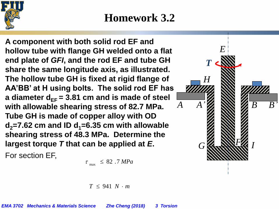
A component with both solid rod EF and
hollow tube with flange GH welded onto a flat
end plate of GFI, and the rod EF and tube GH
share the same longitude axis, as illustrated.
The hollow tube GH is fixed at rigid flange of
AA’BB’ at H using bolts. The solid rod EF has
a diameter dEF = 3.81 cm and is made of steel
with allowable shearing stress of 82.7 MPa.
Tube GH is made of copper alloy with OD
d2=7.62 cm and ID d1=6.35 cm with allowable
shearing stress of 48.3 MPa. Determine the
largest torque T that can be applied at E.
For section EF,
E
F
H
G
T
I
A A’ B B’
MPa7.82max
mNT 941
EMA 3702 Mechanics & Materials Science Zhe Cheng (2018) 3 Torsion
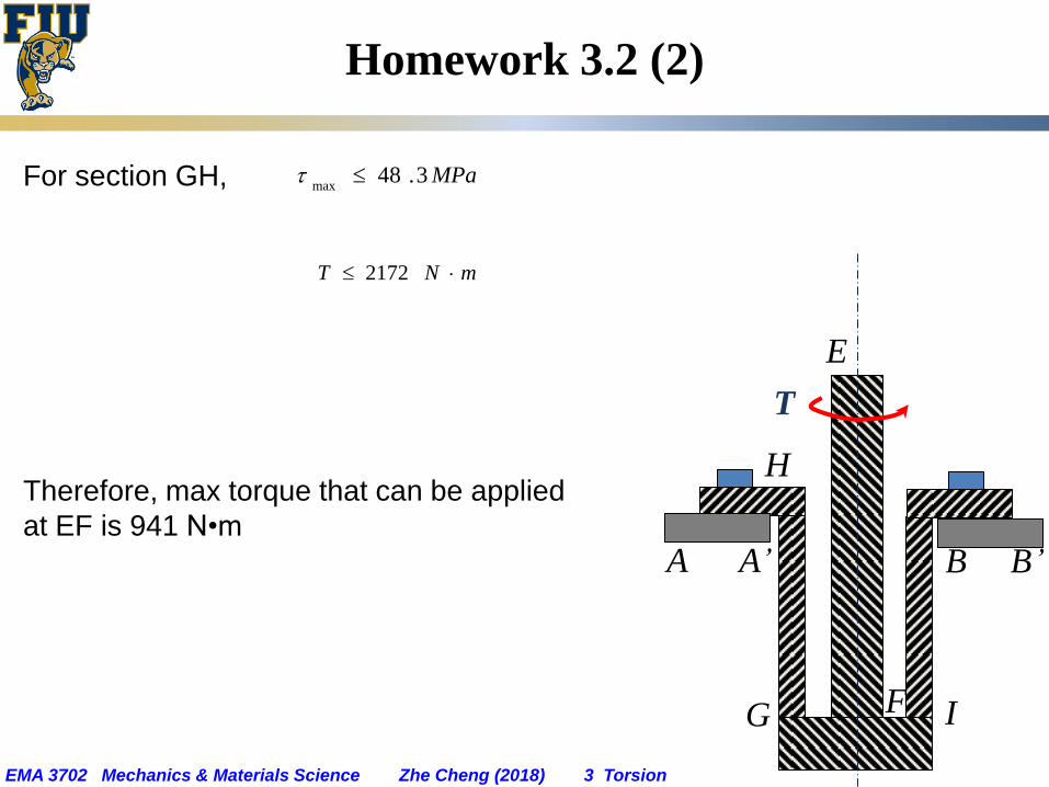
Homework 3.2 (2)
For section GH,
Therefore, max torque that can be applied
at EF is 941 N•m
E
F
H
G
T
I
A A’ B B’
MPa3.48max
mNT 2172

EMA 3702 Mechanics & Materials Science Zhe Cheng (2018) 3 Torsion
Homework 3.3 (1)
Two solid shafts GH and IJ are connected by gears K and L as illustrated.
The radius for gear K is RK = 4 in, while radius for gear L is RL= 2.5 in.
Both two shafts of GH and IJ are made of same steel with allowable
shearing stress of 8 ksi. The radius for the shafts are cGH = 0.8 in and cIJ =
0.625 in. Please determine the largest torque that can be applied at H.
For GH, G H
RK = 4.0 in
I J
RL = 2.5 in
K
L
inlbT 6430

EMA 3702 Mechanics & Materials Science Zhe Cheng (2018) 3 Torsion
Homework 3.3 (2)
For section IJ, due to the two-gear connection,
Therefore, max T can be applied at H is 4906 lb•in
G H
RK = 4.0 in
I J
RL = 2.5 in
K
L
L
K
LR
R
T
T
inlbT 4906

EMA 3702 Mechanics & Materials Science Zhe Cheng (2018) 3 Torsion
Homework 3.4 (1)
Motor applies torque T = 500 N•m on the HGFE shaft when it is rotating at
a constant speed. Knowing shear modulus G = 27 GPa and the torques
exerted on pulleys B and C are shown. Please calculate the angle of
twist between (a) F and G, and (b) between F and H. Knowing shaft
radius cGF = 2.2 cm; cHG = 2.4 cm; cEF = 2.0 cm;
H G F E
TG = 300 N•m TF= 200 N•m Motor
T = 500 N•m
1.2 m 0.9 m

EMA 3702 Mechanics & Materials Science Zhe Cheng (2018) 3 Torsion
Homework 3.4 (2)
Between F and G, net internal torque = ??
Between G and H, net internal torque = ??
Between F and H, total angle of twist:
38.10242.0 rad
FG
83.10320.0 rad
GH
22.30562.0 rad
FH

EMA 3702 Mechanics & Materials Science Zhe Cheng (2018) 3 Torsion
Homework 3.5
Solid aluminum rod (GAl=26 GPa) is bonded to solid copper alloy rod
(GCu=39 GPa). The radius for both rods are 10 mm. Calculate the
angle of twist with respect to base D at E point and at F point,
respectively.
Between DE,
Between EF
Therefore, for DF,
D E
TF = 50 N•m
0.4 m 0.2 m
F copper aluminum
94.00163.0 rad
DE
81.2049.0 rad
EF
74.30653.0 rad
DF
EMA 3702 Mechanics & Materials Science Zhe Cheng (2018) 3 Torsion
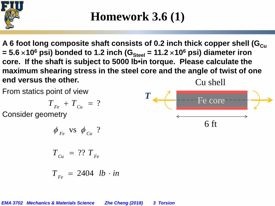
Homework 3.6 (1)
A 6 foot long composite shaft consists of 0.2 inch thick copper shell (GCu
= 5.6 106 psi) bonded to 1.2 inch (GSteel = 11.2 106 psi) diameter iron
core. If the shaft is subject to 5000 lb•in torque. Please calculate the
maximum shearing stress in the steel core and the angle of twist of one
end versus the other.
From statics point of view
Consider geometry
T
Cu shell
Fe core
6 ft
?CuFe
TT
? vsCuFe
FeCuTT ??
inlbTFe
2404
EMA 3702 Mechanics & Materials Science Zhe Cheng (2018) 3 Torsion
Homework 3.6 (2)
Max shearing stress in steel core
Angle of twist:
psiFe
7088max_
35.4076.0 rad
CuFe

EMA 3702 Mechanics & Materials Science Zhe Cheng (2018) 3 Torsion
Homework 3.7
Determine maximum shearing stress in a solid shaft of 10 mm diameter
as it transmits 2.4 kW at a frequency of (a) 30 Hz and (b) 60 Hz.
Max shearing stress
When f = 30 Hz
When f = 60 Hz
??max
Pa7
max1049.6
Pa7
max1025.3

EMA 3702 Mechanics & Materials Science Zhe Cheng (2018) 3 Torsion
Homework 3.8 (1)
Two solid shafts EF and IJ and gears G (RG = 3 inch) and H (RH = 5 inch)
are used to transmit 16 hp (1 hp = 6600 lbin/sec) from motor at E
operating at 1200 rpm (f = 20 Hz) to machine tool at J. Knowing the
maximum allowable shearing stress is 7.5 ksi. Please calculate the
required radius for shaft EF and shaft IJ, respectively.
For EF,
I J
RH = 5.0 in
F E
RG = 3.0 in
H
G
incEF
415.0

EMA 3702 Mechanics & Materials Science Zhe Cheng (2018) 3 Torsion
Homework 3.8 (2)
For IJ
due to gear H and G connection,
I J
RH = 5.0 in
F E
RG = 3.0 in
H
G
EFIJff ??
incIJ
492.0