Eliminating bridge piers using stay cables with ... · PDF fileEliminating bridge piers using...
6
Tailor Made Concrete Structures – Walraven & Stoelhorst (eds) © 2008Taylor & Francis Group, London, ISBN 978-0-415-47535-8 Eliminating bridge piers using stay cables with unconventional layouts A.M. Ruiz-Teran School of Computing andTechnology, University of East London, London, UK A.C. Aparicio Department of Construction Engineering,Technical University of Catalonia, Barcelona, Spain ABSTRACT: This communication explores innovative schemes and shows how in continuous prestressed concrete viaducts of medium length (40m) the inclusion of under-deck or combined stay cables allows the elimination of intermediate or end piers. In these cases, the length of certain spans is doubled, while the main characteristics of the deck (depth, concrete strength, amount of reinforcement, amount of active steel, etc.) can be maintained. These schemes are very appropriate for the situations in which non-structural conditions make a uniform span distribution a non possible option for the design of a viaduct. In addition, it could be an alternative option when a pier of a built bridge has to be shifted due to the widening of an underneath infrastructure. 1 INTRODUCTION Under-deck cable-stayed bridges and combined cable- stayed bridges constitute two innovative bridge types that have been designed and built on only a few occa- sions over the last thirty years by outstanding structural engineers, such as Leonhardt (Fig. 1), Schlaich, Menn, Virlogeux, Manterola, and Cremer. The authors have identified the state-of-the-art of these two new bridge types (Ruiz-Teran 2005, Ruiz-Teran & Aparicio 2007a). Under-deck cable- stayed bridges have stay cables located below the deck (under-deck stay cables). These stay cables are self- anchored in the deck and are deviated by struts that, working in compression, introduce upward deviation forces into the deck. The dead load, the superim- posed dead load, and part of the traffic live load are compensated. Combined cable-stayed bridges have stay cables below and above the deck (combined stay cables). When the stay cables are above the deck, they are deviated by means of pylons that, working under compression, take the downward deviation forces Figure 1. Weitingen viaduct, Germany (courtesy of Holger Svensson, Leonhardt Andrä und Partner). directly to the supports. Whereas when the stay cables are below the deck, they are deviated by struts, that introduce the upward deviation forces into the deck, compensating the dead load, the superimposed dead load, and part of the traffic live load. Both are very efficient bridge types in which the axial response has a significantly larger contribution than the flex- ural response for both permanent and traffic loads (Ruiz-Teran & Aparicio 2007b). Consequently, very slender decks can be designed, with great reduction in the amounts of structural materials in compari- son with conventional bridges without stay cables (Ruiz-Teran & Aparicio 2007c, d). Both bridge types are highly suitable for prestressed concrete decks of medium-length spans. For single-span bridges with 80m spans, the deck depth is reduced to 1/80 of the span, and the amounts of materials are reduced to one third of those in conventional prestressed concrete bridges without stay cables (Ruiz-Teran & Aparicio 2007c). For continuous bridges with 80 m main spans, the deck depth is reduced to 1/100 of the main span, and the amounts of material are halved in comparison with conventional schemes such as contin- uous prestressed concrete bridges without stay cables (Ruiz-Teran & Aparicio 2007d). In viaducts with continuous schemes, a uniform dis- tribution of main spans bounded by shorter end spans is convenient in order to have a balanced distribution of internal forces and deflections throughout the whole viaduct (Leonhardt 1986). However, these schemes, that are advisable from a structural standpoint, can not always be used due to additional conditions that the infrastructure has to satisfy. For example, sometimes, 645
Transcript of Eliminating bridge piers using stay cables with ... · PDF fileEliminating bridge piers using...
Tailor Made Concrete Structures – Walraven & Stoelhorst (eds)© 2008 Taylor & Francis Group, London, ISBN 978-0-415-47535-8
Eliminating bridge piers using stay cables with unconventional layouts
A.M. Ruiz-TeranSchool of Computing and Technology, University of East London, London, UK
A.C. AparicioDepartment of Construction Engineering, Technical University of Catalonia, Barcelona, Spain
ABSTRACT: This communication explores innovative schemes and shows how in continuous prestressedconcrete viaducts of medium length (40 m) the inclusion of under-deck or combined stay cables allows theelimination of intermediate or end piers. In these cases, the length of certain spans is doubled, while the maincharacteristics of the deck (depth, concrete strength, amount of reinforcement, amount of active steel, etc.) canbe maintained. These schemes are very appropriate for the situations in which non-structural conditions make auniform span distribution a non possible option for the design of a viaduct. In addition, it could be an alternativeoption when a pier of a built bridge has to be shifted due to the widening of an underneath infrastructure.
1 INTRODUCTION
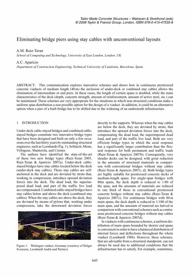
Under-deck cable-stayed bridges and combined cable-stayed bridges constitute two innovative bridge typesthat have been designed and built on only a few occa-sions over the last thirty years by outstanding structuralengineers, such as Leonhardt (Fig. 1), Schlaich, Menn,Virlogeux, Manterola, and Cremer.
The authors have identified the state-of-the-artof these two new bridge types (Ruiz-Teran 2005,Ruiz-Teran & Aparicio 2007a). Under-deck cable-stayed bridges have stay cables located below the deck(under-deck stay cables). These stay cables are self-anchored in the deck and are deviated by struts that,working in compression, introduce upward deviationforces into the deck. The dead load, the superim-posed dead load, and part of the traffic live loadare compensated. Combined cable-stayed bridges havestay cables below and above the deck (combined staycables). When the stay cables are above the deck, theyare deviated by means of pylons that, working undercompression, take the downward deviation forces
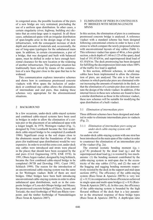
Figure 1. Weitingen viaduct, Germany (courtesy of HolgerSvensson, Leonhardt Andrä und Partner).
directly to the supports. Whereas when the stay cablesare below the deck, they are deviated by struts, thatintroduce the upward deviation forces into the deck,compensating the dead load, the superimposed deadload, and part of the traffic live load. Both are veryefficient bridge types in which the axial responsehas a significantly larger contribution than the flex-ural response for both permanent and traffic loads(Ruiz-Teran & Aparicio 2007b). Consequently, veryslender decks can be designed, with great reductionin the amounts of structural materials in compari-son with conventional bridges without stay cables(Ruiz-Teran & Aparicio 2007c, d). Both bridge typesare highly suitable for prestressed concrete decks ofmedium-length spans. For single-span bridges with80m spans, the deck depth is reduced to 1/80 ofthe span, and the amounts of materials are reducedto one third of those in conventional prestressedconcrete bridges without stay cables (Ruiz-Teran &Aparicio 2007c). For continuous bridges with 80 mmain spans, the deck depth is reduced to 1/100 of themain span, and the amounts of material are halved incomparison with conventional schemes such as contin-uous prestressed concrete bridges without stay cables(Ruiz-Teran & Aparicio 2007d).
In viaducts with continuous schemes, a uniform dis-tribution of main spans bounded by shorter end spansis convenient in order to have a balanced distribution ofinternal forces and deflections throughout the wholeviaduct (Leonhardt 1986). However, these schemes,that are advisable from a structural standpoint, can notalways be used due to additional conditions that theinfrastructure has to satisfy. For example, sometimes,
645
in congested areas, the possible locations of the piersof a new bridge are very restrained, precluding theuse of a uniform span distribution. In other cases, acertain singularity (river, highway, building etc) dic-tates that an extra-large span is required. In all thesecases, unbalanced spans with an irregular distributionof span-lengths arise in the design stage of the newinfrastructure, with the consequent increase of deckdepth and amounts of materials and, occasionally, theuse of long-span typologies for the unbalanced mainspan. In addition, in certain circumstances, a pier ofa bridge, that was designed and built with balancedspans, must be shifted in order to have enough hori-zontal clearance for the new location or the wideningof another infrastructure. This particular situation hastraditionally been solved by means of the construc-tion of a new flag-pier close to the span that has to bewidened.
This communication explores innovative schemesand shows how in continuous prestressed concreteviaducts with 40 m spans the inclusion of under-deck or combined stay cables allows the eliminationof intermediate and end piers, thus making theseschemes very appropriate for the aforementionedsituations.
2 BACKGROUND
In a few occasions, under-deck cable-stayed systemsand combined cable-stayed systems have been usedin bridges in order to allow the elimination of a cer-tain pier or the placement of an unbalanced span witha longer length. In 1978, Weitingen viaduct (Fig. 1),designed by Fritz Leonhardt became the first under-deck cable-stayed bridge to be completed (Leonhardt1986). Significant creep in the soil slopes close tothe abutments meant that the foundations of the endpiers (for traditional span distribution) would be veryexpensive. In order to avoid this extra-cost, under-deckstay cables were introduced and struts were placedin the places that should have been occupied by theend piers (Civil Engineering 1978; ENR 1978). In1991, ObereArgen viaduct, designed by Jorg Schlaich,became the first combined cable-stayed bridge to becompleted (WTB and Dywidag 1991; Cazet 1992;Schlaich 1999). The reason for the introduction ofan unconventional cable-staying system was the sameas for Weitingen viaduct. Both of them are steelbridges. Other bridges have been built introducingunconventional cable-staying systems in order to allowunbalanced span distributions, such as in the com-posite bridges of Losa-del-Obispo bridge and Meaux;the prestressed concrete bridges of Glacis, Ayumi, andTorizaki; the steel footbridge of Weil-am-Rhein view-point; and the timber footbridge of Numedalslagen(Ruiz-Teran & Aparicio 2007).
3 ELIMINATION OF PIERS IN CONTINUOUSPC BRIDGES WITH MEDIUM-LENGTHSPANS
In this section, the elimination of piers in a continuousprestressed concrete bridge is analysed. A referenceviaduct with a standard scheme has been designedfollowing conventional criteria in order to have a ref-erence to which compare the newly proposed schemeswith unconventional layouts of stay cables (Table 1).This reference viaduct has spans of 40 m, a box-girdersection, a deck depth of 1.60 m (1/25 of the span), deadload of 191.85 kN/m, and superimposed dead load of43.10 kN/m. The deck prestressing has been designedfor fulfilling the decompression limit state when 100%of the traffic live load is applied.
In this section, different schemes, in which staycables have been implemented to allow the elimina-tion of piers, are analysed. The aim is to find newschemes in which particular piers are eliminated with-out increasing the amounts of materials in the deck, sothat the elimination of a certain pier does not determi-nate the design of the whole viaduct. In addition, if theinternal forces in these new schemes are found to havea similar distribution as those in the reference viaduct,these new schemes will be suitable for modifying thespan distribution of a built viaduct.
3.1 Elimination of intermediate piers
Three different schemes have been designed and stud-ied in order to eliminate intermediate piers in viaducts(Fig. 2).
3.1.1 Elimination of intermediate piers using anunder-deck cable-staying system withone strut
An under-deck cable-staying system with one strut hasbeen introduced in the main span of the viaduct in orderto counteract the elimination of an intermediate pierof the viaduct (Fig. 2a).
The external isostatic bending moment ((g1 +g2)L2/8) produced by the dead load (g1) and thesuperimposed dead load (g2) is resisted by two mech-anisms: (1) the bending moment contributed by thecable-staying system in mid-span due to the eccen-tricity of the stay cables (31%), and (2) the sum ofthe hogging and sagging bending moments respec-tively resisted by the deck in the support and mid-spansections (69%). The efficiency of the cable-stayingsystem (Ruiz-Teran & Aparicio 2007b) is very low(ξ = 0.31) in comparison to those efficiencies achievedin single-span and multi-span bridges (ξ = 0.9) (Ruiz-Teran &Aparicio 2007c, d). In this case, the efficiencyof the cable-staying system is bounded by the highflexural stiffness of the deck that is a key parame-ter in the structural response of these bridge types(Ruiz-Teran & Aparicio 2007b). A depth/span ratio
646
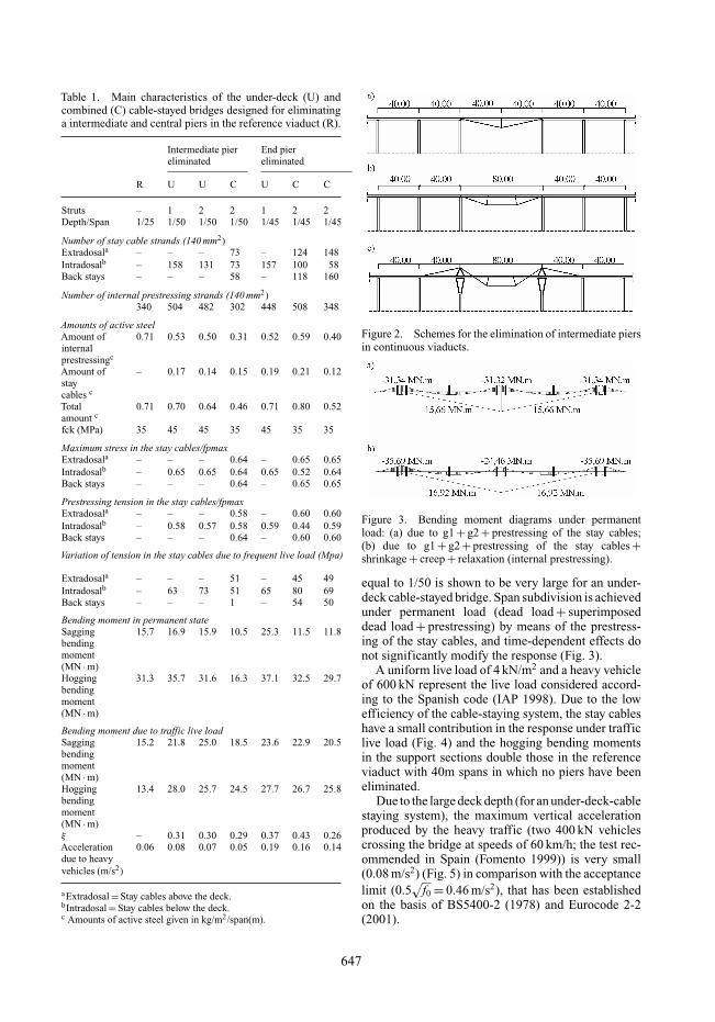
Table 1. Main characteristics of the under-deck (U) andcombined (C) cable-stayed bridges designed for eliminatinga intermediate and central piers in the reference viaduct (R).
Intermediate pier End piereliminated eliminated
R U U C U C C
Struts – 1 2 2 1 2 2Depth/Span 1/25 1/50 1/50 1/50 1/45 1/45 1/45
Number of stay cable strands (140 mm2)Extradosala – – – 73 – 124 148Intradosalb – 158 131 73 157 100 58Back stays – – – 58 – 118 160
Number of internal prestressing strands (140 mm2)340 504 482 302 448 508 348
Amounts of active steelAmount of 0.71 0.53 0.50 0.31 0.52 0.59 0.40internalprestressingc
Amount of – 0.17 0.14 0.15 0.19 0.21 0.12staycables c
Total 0.71 0.70 0.64 0.46 0.71 0.80 0.52amount c
fck (MPa) 35 45 45 35 45 35 35
Maximum stress in the stay cables/fpmaxExtradosala – – – 0.64 – 0.65 0.65Intradosalb – 0.65 0.65 0.64 0.65 0.52 0.64Back stays – – – 0.64 – 0.65 0.65
Prestressing tension in the stay cables/fpmaxExtradosala – – – 0.58 – 0.60 0.60Intradosalb – 0.58 0.57 0.58 0.59 0.44 0.59Back stays – – – 0.64 – 0.60 0.60
Variation of tension in the stay cables due to frequent live load (Mpa)
Extradosala – – – 51 – 45 49Intradosalb – 63 73 51 65 80 69Back stays – – – 1 – 54 50
Bending moment in permanent stateSagging 15.7 16.9 15.9 10.5 25.3 11.5 11.8bendingmoment(MN · m)Hogging 31.3 35.7 31.6 16.3 37.1 32.5 29.7bendingmoment(MN · m)
Bending moment due to traffic live loadSagging 15.2 21.8 25.0 18.5 23.6 22.9 20.5bendingmoment(MN · m)Hogging 13.4 28.0 25.7 24.5 27.7 26.7 25.8bendingmoment(MN · m)ξ – 0.31 0.30 0.29 0.37 0.43 0.26Acceleration 0.06 0.08 0.07 0.05 0.19 0.16 0.14due to heavyvehicles (m/s2)
aExtradosal = Stay cables above the deck.bIntradosal = Stay cables below the deck.c Amounts of active steel given in kg/m2/span(m).
Figure 2. Schemes for the elimination of intermediate piersin continuous viaducts.
Figure 3. Bending moment diagrams under permanentload: (a) due to g1 + g2 + prestressing of the stay cables;(b) due to g1 + g2 + prestressing of the stay cables +shrinkage + creep + relaxation (internal prestressing).
equal to 1/50 is shown to be very large for an under-deck cable-stayed bridge. Span subdivision is achievedunder permanent load (dead load + superimposeddead load + prestressing) by means of the prestress-ing of the stay cables, and time-dependent effects donot significantly modify the response (Fig. 3).
A uniform live load of 4 kN/m2 and a heavy vehicleof 600 kN represent the live load considered accord-ing to the Spanish code (IAP 1998). Due to the lowefficiency of the cable-staying system, the stay cableshave a small contribution in the response under trafficlive load (Fig. 4) and the hogging bending momentsin the support sections double those in the referenceviaduct with 40m spans in which no piers have beeneliminated.
Due to the large deck depth (for an under-deck-cablestaying system), the maximum vertical accelerationproduced by the heavy traffic (two 400 kN vehiclescrossing the bridge at speeds of 60 km/h; the test rec-ommended in Spain (Fomento 1999)) is very small(0.08 m/s2) (Fig. 5) in comparison with the acceptancelimit (0.5
√f0 = 0.46 m/s2), that has been established
on the basis of BS5400-2 (1978) and Eurocode 2-2(2001).
647
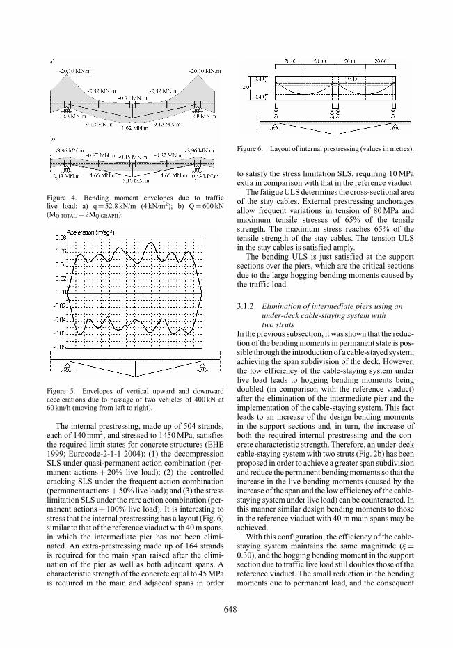
Figure 4. Bending moment envelopes due to trafficlive load: a) q = 52.8 kN/m (4 kN/m2); b) Q = 600 kN(MQ TOTAL = 2MQ GRAPH).
Figure 5. Envelopes of vertical upward and downwardaccelerations due to passage of two vehicles of 400 kN at60 km/h (moving from left to right).
The internal prestressing, made up of 504 strands,each of 140 mm2, and stressed to 1450 MPa, satisfiesthe required limit states for concrete structures (EHE1999; Eurocode-2-1-1 2004): (1) the decompressionSLS under quasi-permanent action combination (per-manent actions + 20% live load); (2) the controlledcracking SLS under the frequent action combination(permanent actions + 50% live load); and (3) the stresslimitation SLS under the rare action combination (per-manent actions + 100% live load). It is interesting tostress that the internal prestressing has a layout (Fig. 6)similar to that of the reference viaduct with 40 m spans,in which the intermediate pier has not been elimi-nated. An extra-prestressing made up of 164 strandsis required for the main span raised after the elimi-nation of the pier as well as both adjacent spans. Acharacteristic strength of the concrete equal to 45 MPais required in the main and adjacent spans in order
Figure 6. Layout of internal prestressing (values in metres).
to satisfy the stress limitation SLS, requiring 10 MPaextra in comparison with that in the reference viaduct.
The fatigue ULS determines the cross-sectional areaof the stay cables. External prestressing anchoragesallow frequent variations in tension of 80 MPa andmaximum tensile stresses of 65% of the tensilestrength. The maximum stress reaches 65% of thetensile strength of the stay cables. The tension ULSin the stay cables is satisfied amply.
The bending ULS is just satisfied at the supportsections over the piers, which are the critical sectionsdue to the large hogging bending moments caused bythe traffic load.
3.1.2 Elimination of intermediate piers using anunder-deck cable-staying system withtwo struts
In the previous subsection, it was shown that the reduc-tion of the bending moments in permanent state is pos-sible through the introduction of a cable-stayed system,achieving the span subdivision of the deck. However,the low efficiency of the cable-staying system underlive load leads to hogging bending moments beingdoubled (in comparison with the reference viaduct)after the elimination of the intermediate pier and theimplementation of the cable-staying system. This factleads to an increase of the design bending momentsin the support sections and, in turn, the increase ofboth the required internal prestressing and the con-crete characteristic strength. Therefore, an under-deckcable-staying system with two struts (Fig. 2b) has beenproposed in order to achieve a greater span subdivisionand reduce the permanent bending moments so that theincrease in the live bending moments (caused by theincrease of the span and the low efficiency of the cable-staying system under live load) can be counteracted. Inthis manner similar design bending moments to thosein the reference viaduct with 40 m main spans may beachieved.
With this configuration, the efficiency of the cable-staying system maintains the same magnitude (ξ =0.30), and the hogging bending moment in the supportsection due to traffic live load still doubles those of thereference viaduct. The small reduction in the bendingmoments due to permanent load, and the consequent
648
reduction of the design bending moments, allow reduc-tions of 19% and 4% in the amounts of reinforcedand internal prestressing of the deck respectively. Therequired cross-section area of the stay cables is alsoreduced by 17%.
3.1.3 Elimination of intermediate piers using acombined cable-staying system with two struts
A combined cable-staying system with two struts(Fig. 2c) has been introduced in the main span ofthe viaduct in order to study whether this scheme isas appropriate as when the combined stay cables areimplemented in all the spans of continuous bridges(Ruiz-Teran & Aparicio 2007d). In the latter case, theeccentricity provided to the stay cables at the supportsections activates the axial response in those sections(due to the couple contributed by the stay cables),increasing the efficiency of the cable-staying sys-tem and reducing the flexural response. In particular,major reductions are achieved in the hogging bendingmoments in the deck at the support sections over thepiers. Unfortunately, the efficiency of the cable stayingsystem is not increased at all (ξ = 0.30). The requiredcross-sectional area of the stay cables is halved, but theamount of external prestressing is not reduced due tothe need to deploy back stays. In this case, the amountof internal prestressing and the characteristic concretestrength can have identical values to those in the ref-erence viaduct, but this fact is due to a reduction inthe span length caused by the type of pylon designedand not due to an increase in the efficiency of thecable-staying system.
3.2 Elimination of end piers
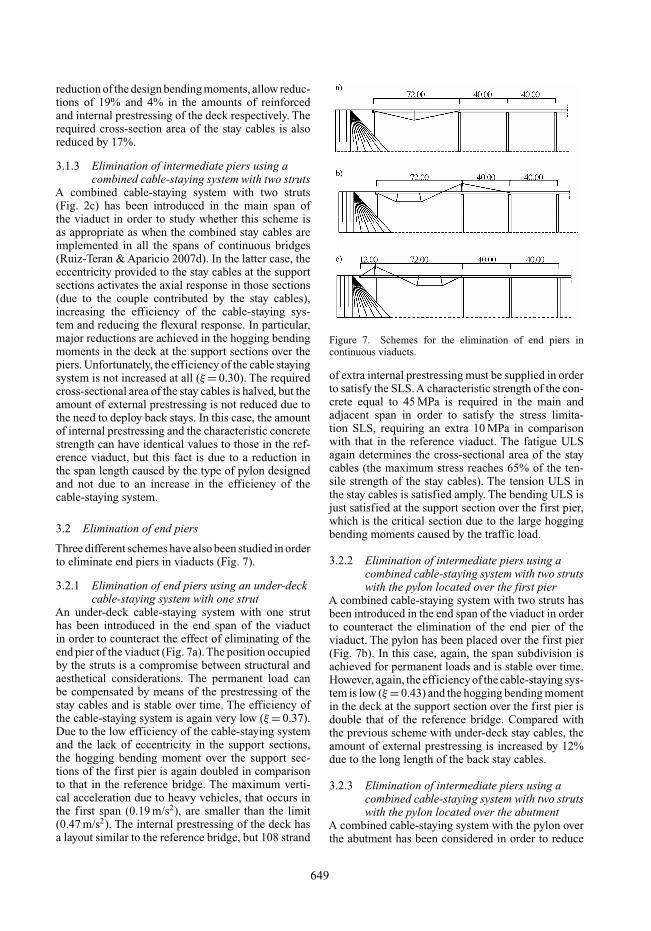
Three different schemes have also been studied in orderto eliminate end piers in viaducts (Fig. 7).
3.2.1 Elimination of end piers using an under-deckcable-staying system with one strut
An under-deck cable-staying system with one struthas been introduced in the end span of the viaductin order to counteract the effect of eliminating of theend pier of the viaduct (Fig. 7a). The position occupiedby the struts is a compromise between structural andaesthetical considerations. The permanent load canbe compensated by means of the prestressing of thestay cables and is stable over time. The efficiency ofthe cable-staying system is again very low (ξ = 0.37).Due to the low efficiency of the cable-staying systemand the lack of eccentricity in the support sections,the hogging bending moment over the support sec-tions of the first pier is again doubled in comparisonto that in the reference bridge. The maximum verti-cal acceleration due to heavy vehicles, that occurs inthe first span (0.19 m/s2), are smaller than the limit(0.47 m/s2). The internal prestressing of the deck hasa layout similar to the reference bridge, but 108 strand
Figure 7. Schemes for the elimination of end piers incontinuous viaducts.
of extra internal prestressing must be supplied in orderto satisfy the SLS. A characteristic strength of the con-crete equal to 45 MPa is required in the main andadjacent span in order to satisfy the stress limita-tion SLS, requiring an extra 10 MPa in comparisonwith that in the reference viaduct. The fatigue ULSagain determines the cross-sectional area of the staycables (the maximum stress reaches 65% of the ten-sile strength of the stay cables). The tension ULS inthe stay cables is satisfied amply. The bending ULS isjust satisfied at the support section over the first pier,which is the critical section due to the large hoggingbending moments caused by the traffic load.
3.2.2 Elimination of intermediate piers using acombined cable-staying system with two strutswith the pylon located over the first pier
A combined cable-staying system with two struts hasbeen introduced in the end span of the viaduct in orderto counteract the elimination of the end pier of theviaduct. The pylon has been placed over the first pier(Fig. 7b). In this case, again, the span subdivision isachieved for permanent loads and is stable over time.However, again, the efficiency of the cable-staying sys-tem is low (ξ = 0.43) and the hogging bending momentin the deck at the support section over the first pier isdouble that of the reference bridge. Compared withthe previous scheme with under-deck stay cables, theamount of external prestressing is increased by 12%due to the long length of the back stay cables.
3.2.3 Elimination of intermediate piers using acombined cable-staying system with two strutswith the pylon located over the abutment
A combined cable-staying system with the pylon overthe abutment has been considered in order to reduce
649
the length of the back stays (Fig. 7c). In this case,the efficiency of the cable-staying system is smaller(ξ = 0.26) and the hogging bending moments in thesupport section over the abutment double that in thesupport section over piers in the reference viaduct.However, due to the contribution of the support sec-tion over the abutment in resisting part of the externalisostatic bending moments, the internal prestressingand the characteristic concrete strength are identicalto those in the reference viaduct.
4 DESIGN CRITERIA FOR THE ELIMINATIONOF PIERS IN CONTINUOUS BRIDGES
The following set of design criteria is applicable forthe elimination of piers in continuous bridges.
The deck depth of the viaduct (1/25 of the mainspans) can be maintained in the case of eliminating anintermediate or end pier, doubling the slenderness ofthe deck in those particular spans.
The efficiency of the implemented unconventionalstay cables is very small because of the reduced slen-derness of the deck for an unconventional cable-stayedbridge.
The bending moments under permanent state canbe reduced (span subdivision is achieved due to theprestressing of the stay cables), but the hogging bend-ing moments are those of the reference viaduct. Thedesign strategy must be to counteract the increasein the bending moments due to the traffic live loadwith the reduction of the bending moments in per-manent state. The implementation of either combinedcable-staying systems with two struts or under-deckcable-staying systems with multiple struts in the twoor three spans affected by the elimination of the pierare found to be appropriate schemes for the situationsanalysed herein.
An alternative possibility for achieving an effectivecable staying system is to interrupt the continuity ofthe viaduct at the support sections over the piers thatbound the span with unbalanced length and to designan under-deck cable-stayed independent single-spanfollowing the design criteria proposed for these typesof bridges (Ruiz-Teran & Aparicio 2007c).
5 CONCLUSIONS
Innovative schemes of continuous prestressed concreteviaducts implementing under-deck or combined staycables have been analysed as an optional scheme forthe design of prestressed concrete viaducts when theelimination of intermediate or end piers is required,giving rise to spans with unbalanced length. Thestudy has focused on viaducts with spans of mediumlength (40 m). The inclusion of these unconventionalcable-staying systems allows the elimination of piers,doubling the length of certain spans, while the main
characteristics of the deck (depth, concrete strength,amount of reinforcement, amount of active steel, etc.)can be identical to those in a viaduct where thepiers have not been eliminated. This fact makes theseschemes very interesting for either the design of newbridges with unbalanced spans due to additional non-structural conditions or the adaptation of built bridgesin the case that a pier should be shifted in order toallow the widening of some infrastructure below. Inaddition, a set of design criteria has been established.
REFERENCES
BS 5400-2. 1978. Steel, concrete and composite bridges. Part2. Specification for loads.
Cazet, P. 1992. The steel Obere Argen viaduct (Le viaducmétallique sur l’Oberargen). Bulletin Ponts Metalliques(OTUA), 15: 97–114 (in French).
Civil Engineering. 1978. Cable-stayed bridge with cablesbelow the deck level in Germany. Civil Engineering(ASCE): 18–19.
EHE 1999. Structural Concrete Code. Madrid: Ministerio deFomento (In Spanish).
ENR. 1978. Inverted stayed-girder bridges soil problems.Engineering News Record 23: 18–19.
Eurocode 2-1-1. 2004. Design of Concrete Structures. Part1-1. EN 1992-1-1.
Eurocode 2-2. 2001. Eurocode 2. Design of concrete struc-tures. Part 2. Concrete bridges. EN 1992-2.
Fomento 1999. Guideline for the development of load tests inroad bridges. Madrid: Ministerio de Fomento (in Spanish).
IAP 1998. Actions Code for road bridges design. Madrid:Ministerio de Fomento. (in Spanish).
Leonhardt, F. 1986. Ponts, Puentes. Laussane: Presses poly-techniques romandes.
Ruiz Teran, A.M. 2005. Unconventional cable stayed bridges.Structural behaviour and design criteria”. Doctoral The-sis. Supervisor: Professor A.C. Aparicio. University ofCantabria, Spain. (in Spanish).
Ruiz-Teran, A.M. & Aparicio A.C. 2007a. Two new types ofbridges: under-deck cable-stayed bridges and combinedcable-stayed bridges.The state of the art. Canadian Journalof Civil Engineering 34(8): 1003–1015.
Ruiz-Teran, A.M. & Aparicio A.C. 2007b. Parameters gov-erning the response of under-deck cable-stayed bridges.Canadian Journal of Civil Engineering 34(8): 1016–1024.
Ruiz-Teran, A.M. & Aparicio A.C. 2007c, submitted. Struc-tural behaviour and design criteria of under-deck cable-stayed bridges and combined cable-stayed bridges. Singlespan bridges. Canadian Journal of Civil Engineering.
Ruiz-Teran, A.M. & Aparicio A.C. 2007d, submitted.Structural behaviour and design criteria of under-deck cable-stayed bridges and combined cable-stayedbridges. Multi-span bridges. Canadian Journal of CivilEngineering.
Schlaich, J. 1999. Cable-stayed bridges with special features.IABSE Conference, Malmö.
WTB and Dywidag. 1991. Bridge over Obere Argen val-ley (Talbrücke Obere Argen). Walter-Thosti-Boswau &Dywidag (in German).
650