Eliminarea apei reziduale Waste water disposal ... · – Sc derea nivelului pânzei freatice –...
56
More than pumps Birox/AN/SW FEX/FWX/FMX/FSX Abwasserentsorgung Waste water disposal Eliminarea apei reziduale Abwasserentsorgung Waste water disposal Eliminarea apei reziduale
Transcript of Eliminarea apei reziduale Waste water disposal ... · – Sc derea nivelului pânzei freatice –...

More than pumps
Birox/AN/SWFEX/FWX/FMX/FSX
AbwasserentsorgungWaste water disposalEliminarea apei reziduale
AbwasserentsorgungWaste water disposalEliminarea apei reziduale

Biral VisionVier Kerngedanken bestimmen unser Denken und Handeln:
Wir sind der führende Anbieter von innovativen und effizientenPumpenlösungen.
Fachkompetenz, Nähe zu Kunden und Flexibilität bei der Lösung speziellerKundenanliegen schaffen einen wahrnehmbaren Kundennutzen.
Dabei pflegen wir stets eine respektvolleund vertrauensvolle Partnerschaft zuunseren Kunden und unseren Mitarbeitern.
Unsere Arbeit erfüllt uns mit Stolz und ist Ansporn zugleich, dieses Niveau der Zuverlässigkeit und der Langlebigkeitkonsequent weiterzuverfolgen.
Dabei bauen wir auf kompetenteMitarbeiterinnen und Mitarbeiter,deren Herzen mit ganzer Energie und Passion für Biral schlagen.
Viziunea BiralPatru idei esenţiale determină gândirea şi acţiunea noastră:
Suntem furnizorul de top pentru solu ii de pompe inovatoare i eficiente.
Competen a de specialitate, apropiereade clien i i flexibilitatea fa de cerin elespecifice ale clien ilor creeaz un beneficiu semnificativ pentru clien i.
Men inem in permanen un parteneriatbazat pe respect i incredere cu clien ii i partenerii no tri.
Munca noastr ne face s fim foarte mândri i reprezint stimulentul pen-tru a continua consecvent acest nivel defiabilitate i durabilitate.
Ne bazăm pe angajaţii competenţi,ale căror inimi bat cu energie şi pasiune pentru Biral.
Biral VisionFour core thoughts determine the way we think and act:
We are the leading supplier of innovative and efficient pump solutions.
Technical competence, proximity to the customer and flexibility in solvingspecial customer concerns create perceptible customer benefits.
We constantly maintain a respectful and trustworthy partnership with our customers and partners to achievethis.
Our work fills us with pride and is the incentive to consistently pursue this level of reliability and durability.
We build upon competent employees,who put all their energy and passioninto Biral.
Biral – Von ganzem HerzenBiral – With all our heartBiral – Din inim

Mehr als PumpenWo Vision, Werte und Verantwortungfür Sie spürbar werden.
Kompetenz– Kompetente Beratung jederzeit
auf Abruf– Biral campus –
das neue SchweizerPumpen-Kompetenzzentrum
Zuverlässigkeit– Innovative Produkte von höchster
Qualität– Eine lückenlose Palette
für alle Einsatzbereiche– Eine Logisitik, die ohne Zeitverzögerung
reagieren kann
Kundennähe– Virtuelle Planungsunterstützung– Nutzerfreundliche Dokumentationen
und Datengrundlagen– Eine Serviceorganisation,
die rund um die Uhr für Sie da ist
Mai mult decât pompeAcolo unde viziunea, valorile şi responsabilitatea sunt vizibile pentru dvs.
Competenţă– Consiliere competent oricând
la cerere– Campusul Biral –
noul centru de competenpentru pompe din Elve ia
Fiabilitate– Produse inovatoare de cea mai
bun calitate– O palet complet pentru toate
domeniile de utilizare– O logistic , ce poate reac iona
f r întârziere
Aproape de clienţi– Asisten la proiectare– Documenta ii u oare pentru utilizatori
i seturi de date– O organiza ie de service,
care este prezent permanent pentru dvs.
More than pumpsWhere vision, values and responsibilitybecome palpable to you.
Competence– Competent consultation
as required– Biral campus –
the new Swiss pump competence centre
Reliability– Innovative products
of the highest quality– A full range for all areas of use– Logistics that respond
without delay
Proximity to customers– Virtual planning support– User-friendly documentation
and data sources– A service organisation that is there
for you around the clock
Biral – Ihr führender Partner für innovative und effiziente PumpenlösungenBiral – your leading partner for innovative and efficient pump solutionsBiral – partenerul dvs. de top pentru solu ii de pompe inovatoare i eficiente
KompetenzCompetence
CompetenţăZuverlässigkeit
ReliabilityFiabilitate
KundennäheProximity to customers
Aproape de clienţi

Abwasserentsorgung
Pumpen für die Abwasserentsorgung –Sicherheit über alles!Pumpen von Biral sprechen fürFunktionalität und Zuverlässigkeit.Diese Qualitäten gelten sowohl für diekleinen, leichten und steckerfertigenChromstahlpumpen wie auch für dierobusten Graugusspumpen für den professionellen Einsatz.
Mehrzweckpumpen Birox 80, 90, 100, 150, 200Die ideale Pumpe für kleinere Haushalt-anlagen. Sie kann stationär oder mobileingesetzt werden. Geeignet für verschmutztes Wasser ohne aggressive Beimengungen mitgeringen Festbestandteilen, jedoch nicht für Fäkalien, langfaserigeVerunreinigungen, brennbare oder explosive Medien wie Öl oder Benzin. Mit oder ohne Schwimmer lieferbar.Wartungsarm, leicht und handlich.
Abwasserpumpen ANM, ANE, ANWRobuste, zuverlässige Abwasserpumpenfür den stationären Einsatz in Gärtnereienund in der Landwirtschaft. Für dieEntwässerung von Einstellhallen und den Dauergebrauch in der Industrie.Robuste Gussbauweise, grosserKugeldurchgang, separate Niveau-einstellung, guter Wirkungsgrad durchdie Möglichkeit, das Laufrad an dasFördermedium (Menge und Konsistenz)anzupassen.
Schmutzwasserpumpe SWSchlanke Pumpe mit obenliegendemDruckanschluss für den stationären/portablen Einsatz bei begrenztenPlatzverhältnissen, für allgemeineEntwässerungsaufgaben, etc.Das Fördermedium umströmt und kühltden Motor optimal. Dadurch wird einSchlürfbetrieb, also das Betreiben der Pumpe bei niedrigem Wasserstand,zulässig.
Waste water disposal
Pumps for waste water disposal – reliability above all!Pumps from Biral are distinguished by their functionality and dependability.These qualities are shared by both the small, lightweight chromium steelpumps ready for connection and also by the robust, cast iron pumps for industrial applications.
Multi-purpose pumpsBirox 80, 90, 100, 150, 200The ideal pump for smaller domesticinstallations. It can be used for mobile or stationary applications.Suitable for contaminated water withoutaggressive additives with low proportionof solid matter, but not for sewage, long-fibred contaminants or combustibleand explosive media, such as oil or gasoline. Available with or withoutfloat. Low maintenance, light and easy to handle.
Waste water pumps ANM, ANE, ANWRobust, reliable waste water pumps for stationary applications in horticultureand agriculture. For draining parkinggarages and for continuous operation in industry. Robust cast construction,large ball passage, separate level adjustment, high efficiency with the possibility of adapting the impeller to the medium conveyed (volume and consistency).
Waste water pump SWCompact pump with pressure line at top for stationary/portable applicationin confined spaces, for general drainagefunctions, etc. The medium deliveredflows round and cools the motor in an optimum way. This permits slurpoperation, i.e. operation of the pump with low water level.
Eliminarea apei reziduale
Pompe pentru eliminarea apei reziduale –Siguran absolut !Pompele de la Biral se disting prin func ionalitate i fiabilitate.Aceste calit i sunt valabile atât pentrupompele din o el cromat, mici, u oare ipreg tite pentru racordare, cât i pentrupompele robuste din font gri, pentru aplica ii industriale.
Pompe universale Birox 80, 90, 100, 150, 200Pompa ideal pentru instala iile casnicemici. Aceasta se poate utiliza sta ionarsau mobil. Este adecvat pentru apa murdar f ramestecuri agresive, cu cantita i mici de substan e solide, dar nu cu fecale,impurit i cu fibre lungi, fluide inflamabilesau explozive, cum ar fi uleiul sau benzina. Disponibil cu sau f r flotor. Nu necesit între inere, este u oar i manevrabil .
Pompe pentru apă reziduală ANM, ANE, ANWPompe robuste, fiabile pentru ap rezidual , pentru utilizarea sta ionar în gr din rit i în agricultur . Pentru drenarea garajelor i func ionareacontinu în industrie. Construc ie robustdin font , orificiu mare pentru bil , setareseparat a nivelului, înalt eficien cuposibilitatea de a adapta rotorul la fluid(cantitate i consisten ).
Pompă pentru apă murdară SWPomp îngust cu racord superior sub presiune pentru utilizarea sta ionar /portabil în condi ii de spa iu limitat, pentru sarcini generale de drenare etc.Fluidul circul i r ce te motorul în modoptim. Astfel este permis o func ionarecu aspirare, deci func ionarea pompei cu un nivel de ap redus.
Die richtige Pumpe am richtigen PlatzWhy it’s always worth choosing BiralLa pompa giusta al posto giusto
4

Fäkalienpumpen FEX, FWX, FMX, FSXEin ausgewogenes Sortiment vonPumpen mit den dazugehörigenSchachtsystemen, leicht zu montierenund gut aufeinander abgestimmt: Jede von ihnen kann dort eingesetzt werden, wo sie mit grösstemWirkungsgrad arbeitet.Ihre hohe Zuverlässigkeit verdankenFäkalienpumpen von Biral einer ganzenReihe von konstruktiven Merkmalen.
Dazu gehören:– Die bewährte Hydraulik
mit ihrem hohen Wirkungsgrad – Die solide Konstruktion, die sich
in vielen Anwendungen bewährt hat– Die doppelte Gleitringdichtung
und die Ölsperrkammer verhindern das Eindringen von Wasser im Motor
– Ein Dichtungssensor zeigt eine allfällige Infiltration von Wasser durch die Gleitringdichtung frühzeitig an
– Speziell entwickelte Steuergeräte für niveauabhängige Pumpenschaltung.Mit grafischem Display, Text-Anzeigen und intuitiver Bedienung.
Sewage pumps FEX, FWX, FMX, FSXA well-balanced range of pumps with the associated manhole systems, easilyinstalled and mutually well matched:they can all be installed where they operate with the highest efficiency. The high reliability of Biral sewage pumpsis the result of a whole range of design features.
These include:– The proven hydraulics,
high efficiency single-channel impeller– Solid construction fully proven
in many applications– Double floating ring seal and oil barrier
chamber prevent the penetration of water into the motor
– A sealing sensor indicates any infiltration of water through the floating ring seal in good time
– Specially developed control units for pump switching dependent on level. With graphic display, text messages and intuitive operation.
Pompe pentru fecale FEX, FWX, FMX, FSXO gam bine echilibrat de pompe cu siste-mele de pu uri aferente, u or de montat ibine armonizate: oricare dintre acestease poate monta acolo unde func ioneaz cu cel mai mare randament.Fiabilitatea sporit a pompelor Biral pentru fecale se datoreaz unei întregigame de caracteristici constructive.
Dintre acestea fac parte:– Sistemul hidraulic brevetat
cu randamentul s u ridicat – Construc ia solid , care i-a demonstrat
valoarea în numeroase aplica ii– Etan area mecanic dubl i camera
de blocare a uleiului împiedic p trunderea apei în motor
– Un senzor de etan eitate indic din timp o eventual infiltrare a apei prin etan area mecanic
– Dispozitive de comand dezvoltate special pentru comutarea pompei în func ie de nivel. Cu afi aj grafic, afi are cu text i utilizare intuitiv .
5

6

Mehrzweckpumpen Birox Seite/Page/Pagina 9
Multi-purpose pumps Birox
Pompe universale Birox
Abwasserpumpen ANE, ANM, ANW 15
Waste water pumps ANE, ANM, ANW
Pompe pentru apa reziduală ANE, ANM, ANW
Schmutzwasserpumpen SW 19
Waste water pumps SW
Pompe pentru apa murdară SW
Abwasser- und Fäkalienpumpen 23
Waste water and sewage pumps
Pompe pentru apa reziduală şi fecale
Armaturen 44
Fittings
Robinete
Steuergeräte BS 47
Control devices BS
Dispozitive de comandă BS
InhaltsübersichtTable of contentsCuprins
7
Bir
oxA
NE
/AN
M/A
NW
SW
FEX
/FW
X/F
MX
/FS
XA
rmat
uren
/Rob
inet
eB
S

Abmessungen in mmTechnische Änderungen vorbehalten
Dimensions in mmTechnical changes reserved
Dimensiuni în mmNe rezerv m dreptul de a efectua modific ri tehnice
MehrzweckpumpenMulti-purpose pumpsPompe universale
Birox
2800 1/minH
(m)H(ft)
Birox 80
Birox 90
Birox 100
Birox 150
Birox 200
Kennlinien nach EN 9906 K2Characteristic curves according to EN 9906 K2Caracteristici conform EN 9906 K2
Capacity Q (I.G.P.M.)
Förd
erhö
he –
Sta
tic h
ead
–În
lim
ea d
e po
mpa
reH
(m)
Tota
l hea
d H
(fee
t)
Förderstrom – Delivery – Debit Q
9
Bir
ox

10

Pompă universală Biral
Pompa universal din o el inoxidabil de înalt calitate pentru utilizarea transportabil i sta ionar cu i f r comand integrat a nivelului. Pentru pomparea apei u or murdare cu substan e solide (vezi datele tehnice) f r amestecuri agresive.
Domenii de utilizare– Drenarea pivni elor– Drenarea sp l toriilor– Golirea pu ului i a beciului – Golirea recipientelor– Sc derea nivelului pânzei freatice– Adecvat pentru fluide
cu valoarea pH-ului de la 5 pân la 11
Pompa nu este adecvată pentru pomparea de:
– Fecale– Fluide cu componente cu fibre lungi– Fluide inflamabile sau explozive
(ulei, benzin , diluan i de vopsea etc.)– Fluide agresive– Utilizarea în zone cu pericol de explozie
(ATEX)
Atenţie!Func ionarea pompei trebuie s se realizeze numai prin comutatorul de protec ie împotriva curentului de defect. (Intensitatea max. a curentului nominal de declan are a comutatorului de protec ie împotriva curentului de defect 30 mA.)
Avantaje– Construc ie stabil , robust– Mâner pentru transportul u or– Pompa i motorul sunt separate printr-o
unitate de etan are universal– Motor cu protec ie integrat împotriva
suprasarcinii numai la 1× 230 V– Temperatura max. a apei 40 °C– Rotor din o el inoxidabil– Autoriza ii
Biral-Multi-purpose pump
The multi-purpose pump, made of heavy duty stainless steel is designed for stationary as well as for portable application. The pump is equipped with and without a level switch for automatic operation. Contaminated water containing solids (see technical data) but without aggressive additives can be handled.
Fields of application– Basement drainage– Laundry drainage– Evacuation of pits– Pump out of tanks– Lowering of ground-water level – Suitable for media with pH-value
from 5 to 11
The pump is not suitable for conveying:
– sewage– media with long-fibred components– combustible or explosive media
(oil, gasoline, paint thinners, etc.)– aggressive media– Application in areas subject
to explosion (ATEX)
Warning!The pump may only be put into operation using a fault current protective switch. (Max. rated tripping current 30 mA.)
Advantages– Sturdy, robust finish– Carrying handle for easy transport– Pump and motor are separated
by a multi-acting sealing unit– Motor with fitted overload protection
only to 1×230 V– Max. water temperature 40 °C– Impeller made of stainless steel– Approvals
Biral-Mehrzweckpumpe
Die Mehrzweckpumpe aus hochwertigem rostfreiem Edelstahl, für transportablen und stationären Einsatz, mit und ohne angebauter Niveausteuerung. Zur Förderung von leicht verschmutztem Wasser mit Festbestandteilen (siehe technische Daten) ohne aggressive Beimengungen.
Einsatzgebiete– Kellerentwässerung– Waschküchenentwässerung– Schacht- und Grubenentleerung – Auspumpen von Behältern– Grundwasserabsenkung– geeignet für Medien
mit pH-Wert 5 bis 11
Die Pumpe eignet sich nicht für die Förderung von:
– Fäkalien– Medien mit langfaserigen
Bestandteilen– brennbaren oder explosiven Medien
(Öl, Benzin, Farbverdünner u. ä.)– aggressive Medien– Einsatz im explosionsgefährdetem
Bereich (ATEX)
Achtung!Betrieb der Pumpe darf nur über Fehlerstromschutzschalter erfolgen. (Max. Nennauslösestromstärke der Fehlerstromschutzschalter 30 mA.)
Vorteile– Stabile, robuste Ausführung– Handlicher Traggriff für bequemen
Transport– Pumpe und Motor sind durch eine
mehrfachwirkende Dichtungseinheit getrennt
– Motor mit eingebautem Überlastungsschutz nur bei 1× 230 V
– Max. Wassertemperatur 40 °C– Laufrad aus rostfreiem Edelstahl– Zulassungen
11
Passendes Zubehör und Steuerungenab Seite 44
Suitable accessories and control unitsfrom page 44
Accesoriile adecvate şi sistemele de comandă de la pagina 44
Bir
ox
20 9965.1
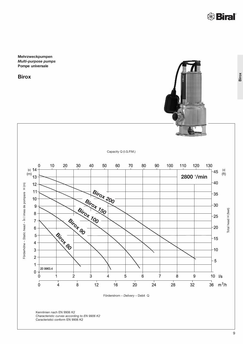
1 Kunststoffschlauch Birox 80: Nr. 05 3591.2699 (11/4”)Synthetic hose Birox 90: Nr. 05 3591.3999 (11/2”)Furtun din plastic Birox 100/150/200: Nr. 05 3591.4199 (2”)
2 Schlauchbride Birox 80: Nr. 05 2351.0700Hose band clip Birox 90: Nr. 05 2351.0800Brid de furtun Birox 100/150/200: Nr. 05 2351.1000
3 Anschlussbogen, Kunststoff Birox 80: Nr. 05 3775.3862 (11/4”)Connection bend, synthetic Birox 90: Nr. 05 3775.3962 (11/2”)Cot de racordare, plastic Birox 100/150/200: Nr. 05 3775.4199 (2”)
Technische Daten/Technical data/Date tehniceBirox 80 Birox 90
Anschluss Connection Racord R 11/4 R 11/2
Korngrösse Granular size Granula ie 20 mm 40 mmmit Schwimmerschalter with float switch cu flotor
05 4777.0150 05 4777.0950ohne Schwimmerschalter without float switch f r flotor
05 4777.2350 05 4777.2650Kabel Cable Cablu 10 m 10 mStecker Plug techer SEV Type 12 Type 12
VDE,ÖVE Schuko SchukoSpannung Voltage Tensiune 1×230 V, 50 Hz 1×230 V, 50 HzLeistungsaufnahme Power consumption Putere absorbit P1 = 0,5 kW 0,9 kWLeistungsabgabe Power output Putere P2 = 0,37 kW 0,6 kWNennstrom Nominal current Curent nominal 2,5 A 4,1 ASchaltungen/h Switching operations/h Comut ri/h 30 30Schutzart Protection Clasa de protec ie IP 68 IP 68Isolationsklasse Insulation class Clasa de izolare F FMotorschutz Motor protection Protec ia motorului(eingebaut) (mounted) (montat)Mediumtemperatur Permissible water Temperatura fluidului
temperature max. 40 °C max. 40 °CEintauchtiefe Immersion depth Adâmcimea de imersare max. 7 m max. 7 mGewicht Weight Greutate 7 kg 8,5 kg
Werkstoffe/Materials/Materiale Birox 80, 90, 100, 150, 200Pumpengehäuse Pump casing Carcasa pompei X5CrNi 1810, 1.4301Laufrad Impeller Rotor G-X6CrNi 189, 1.4308Motorgehäuse Motor casing Carcasa motorului X5CrNi 1810, 1.4301Welle Shaft Arbore X2CrNiMo17132 1.4404Kabel Cable Cablu HO7 RN FSchwimmerschalter Float switch Comutator cu flotor Neoprene / PPH
* Abhängig von der Einstellung des SchwimmerschaltersDependent on setting of float switchÎn func ie de setarea flotorului
3
1
2
ZubehörAccessoriesAccesoriile
Birox 90Birox 80
12
AUSOFFOPRITAUS
OFFOPRIT
EINONPORNIT
EINONPORNIT

Schutzanode Set (Magnesium Anode)zum Schutz der Pumpe vor aggressivem Abwasser(Elektrokorrossion)
Anode stem set (magnesium anode)to protect pump from aggressive waste water (electro-corrosion)
Set de anozi de protec ie (anod de magneziu)pentru protejarea pompei împotriva apei reziduale agresive(coroziunea echipamentului electric) Nr. 20 1125.0100
Birox 100 Birox 100** Birox 150 Birox 150** Birox 200**R 2 R 2 R 2 R 2 R 240 mm 40 mm 40 mm 40 mm 50 mm
05 4777.0250 05 4777.0350
05 4777.2450 05 4777.0850 05 4777.2550 05 4777.045010 m 10 m 10 m 10 m 10 mTyp 12 Typ 12Schuko Schuko1×230 V, 50 Hz 3×400 V, 50 Hz 1×230 V, 50 Hz 3×400 V, 50 Hz 3×400 V, 50 Hz1,3 kW 1,3 kW 1,6 kW 1,6 kW 1,8 kW0,9 kW 0,9 kW 1,2 kW 1,2 kW 1,3 kW5,8 A 2,2 A 7,2 A 2,5 A 3,0 A30 30 30 30 30IP 68 IP 68 IP 68 IP 68 IP 68F F F F F
max. 40 °C max. 40 °C max. 40 °C max. 40 °C max. 40 °C7 m 7 m 7 m 7 m 7 m9 kg 9 kg 10 kg 10 kg 12,6 kg
** Passendes Zubehör und Steuerungen ab Seite 44Suitable accessories and control units from page 44Accesoriu adecvat i sisteme de comand de la pagina 44
Birox 100/150
EINONPORNIT
AlarmAlarm
AUSOFFOPRIT
Birox 200
13
AUSOFFOPRIT
EINONPORNIT
Bir
ox

14

AbwasserpumpenWaste Water PumpsPompe pentru apă reziduală
ANE/ANM/ANW
Capacity Q (I.G.P.M.)
Förderstrom – Delivery – Debit Q
Förd
erhö
he –
Sta
tic h
ead
–În
lim
ea d
e po
mpa
reH
(m)
15
Kennlinien nach EN 9906 K2Characteristic curves according to EN 9906 K2Caracteristici conform EN 9906 K2
ANE, ANM, ANWA
NE
/AN
M/A
NW
Abwasserpumpen
Zur Förderung von Schmutzwasserund Abwasser sind die Biral-Abwasserpumpen bestens geeignet.
Die universale Typenreihe für verschieden-artige Einsatzbereiche wie Haustechnik,Kellerentwässerung, Gärtnereien,Landwirtschaft und Industrie.
Pumpe und Motor der robustenAbwasserpumpe bilden eine Einheit. Als Dichtungssatz sind zwei Gleitring-dichtungen eingebaut. Die obereGleitringdichtung verhindert dasAustreten des Öles ins Motorgehäuse.Das Öl in der Ölsperrkammer verhindert ein Trockenlaufen der unteren, verschleissfesten Hartmetallgleitring-dichtung, welche mediumseitig abdichtet.
Wo und wie Sie Biral-Pumpen auch immer einsetzen, Sie profitieren davon: Biral-Pumpen sind geprüft – betriebssicher – bewährt.
Pompe pentru apă reziduală
Pompele Biral pentru apă reziduală suntadecvate în special pentru pompareaapei murdare şi a apei reziduale.
Seria universal pentru diferite domenii de utilizare, cum ar fi uz casnic, drenarea pivni ei, gr din rit, agricultur i industrie.
Pompa i motorul pompei robuste pentruap rezidual formeaz o unitate. Umplerea cu ulei a motorului garanteazo distribu ie bun a c ldurii. Ca set deetan are, sunt montate dou etan rimecanice. Etan area mecanic superioar împiedic ie irea uleiului în car-casa motorului. Uleiul din camera de blo-care a uleiului împiedic func ionarea peuscat a etan rii mecanice din metal durinferioare, rezistente la uzur , care etan eaz pe circuitul fluidului.
Oriunde i oricum utiliza i pompele Biral, profita i de faptul c : pompele Biral sunt verificate şi brevetateca fiind – sigure în funcţionare.
Waste Water Pumps
Biral waste water pumps are well suited for the delivery of sewage and waste water.
The universal type range for several purposes like the domestic field, cellar drainage, horticulture, agricultureand industry.
Pump and motor of the robust waste-water pump form one unit. Two mechanical seals serve as packing.The gasket set comprises two floatingring seals. The upper floating ring sealprevents oil entering the motor housing.The oil in the oil-barrier chamber stops the lower, wear-proof, carbide floating ring seal, which seals on the fluidside.
How and where you make use of Biral pumps will be to your advantage: Biral pumps are tested – reliable – proven.
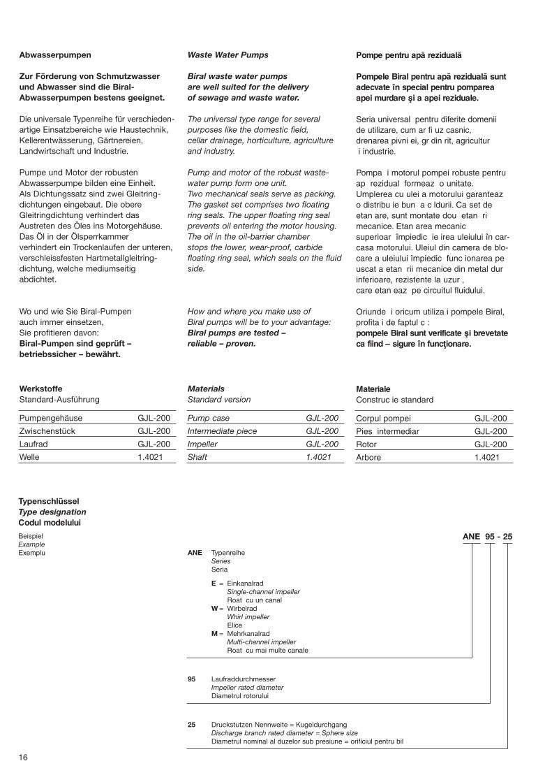
TypenschlüsselType designationCodul modelului
BeispielExampleExemplu
ANE 95 - 25
ANE TypenreiheSeriesSeria
E = EinkanalradSingle-channel impellerRoat cu un canal
W = WirbelradWhirl impellerElice
M = MehrkanalradMulti-channel impellerRoat cu mai multe canale
95 LaufraddurchmesserImpeller rated diameterDiametrul rotorului
25 Druckstutzen Nennweite = KugeldurchgangDischarge branch rated diameter = Sphere sizeDiametrul nominal al duzelor sub presiune = orificiul pentru bil
16
MaterialsStandard version
Pump case GJL-200
Intermediate piece GJL-200
Impeller GJL-200
Shaft 1.4021
WerkstoffeStandard-Ausführung
Pumpengehäuse GJL-200
Zwischenstück GJL-200
Laufrad GJL-200
Welle 1.4021
MaterialeConstruc ie standard
Corpul pompei GJL-200
Pies intermediar GJL-200
Rotor GJL-200
Arbore 1.4021

LaufradformImpeller shapeFormă rotor
ANMDreikanalradThree-channel impellerRoat cu trei canale
Type/Tip
ANM 95-25
Type/Tip
ANM 110-40
Type/Tip
ANE 95-25
ANE 110-40
Type/Tip
ANW 95-25
ANW 110-40
ANMZweikanalradTwo-channel impellerRoat cu dou canale
ANEEinkanalradSingle-channel impellerRoat cu un canal
ANWWirbelradWhirl impellerElice
17
AN
E/A
NM
/AN
W
Motor: P2 = 0,5 kW; 3× 400 V
ANM
ANE
ANW
ANM
ANE
ANW
AN . . 95-252900 1/min
Kugeldurchgang Sphere size
Orificiu pentru bil ∅ 25 mm
AN . . 110-402900 1/min
Kugeldurchgang Sphere size
Orificiu pentru bil ∅ 40 mm
Motor: P2 = 1,2 kW; 3× 400 V
L U
[mm] [mm] [kg]
– 110 50 °C 35 °C 19 20 1131.0150
11 169 – * 20
– 110 50 °C 35 °C 19 20 1131.0250
– 110 50 °C 35 °C 19 20 1131.0350
– 146 50 °C 35 °C 38 20 1130.0150
13 253 – * 39
– 146 50 °C 35 °C 38 20 1130.0250
– 146 50 °C 35 °C 38 20 1130.0350
Technische Daten/Technical data/Date tehnice
IN INP1 P2 3×230V 3×400V G A ØB E H J K
Type/Tip [m] [kW] [kW] [A] [A] [mm] [mm] [mm] [mm] [mm] [mm]
ANE 95-25 10 25 10 0,5 0,3 1,9 1,1 1” 398 227 100 – – –
13 25 10 0,5 0,3 1,9 1,1 1” 457 227 100 40 63 160
ANM 95-25 10 25 10 1,0 0,6 2,8 1,6 1” 398 227 100 – – –
ANW 95-25 10 25 10 0,8 0,5 2,6 1,5 1” 398 227 100 – – –
ANE 110-40 10 40 10 1,3 1,0 5,0 2,9 11/2” 500 261 125 – – –
13 40 10 1,3 1,0 5,0 2,9 11/2” 608 261 125 61 116 140
ANM 110-40 10 40 10 2,1 1,7 6,8 3,9 11/2” 500 261 125 – – –
ANW 110-40 10 40 10 2,1 1,7 6,8 3,9 11/2” 500 261 125 – – –
Kug
eldu
rchg
ang
Sphe
re s
ize
Orif
iciu
pen
tru b
il
Bau
form
(Bf)
Mod
el (B
f)Fo
rm c
onst
ruct
iv (B
f)
Kab
el
Plug
-in
Cab
lu
Ans
chlu
ss
Con
nect
ion
– R
acor
d
Gew
icht
– W
eigh
t– G
reut
ate
Art
ikel
-Nr.
Art.
no.
Nr.
artic
ol
PumpePumpPomp
Motor 50 Hz Masse in mmÄnderungen vorbehaltenDimensions in mmnot bindingDimensiuni în mmNe rezerv m dreptul de a efectua modific ri
Passendes Zubehör und Steuerungen ab Seite 44Suitable accessories and control units from page 44Accesoriile adecvate i sistemele de comand de la pagina 44
18
Max. zulässige Flüssigkeitstemperatur
* 50 °C Trocken-aufstellung (Bf 13)Max allowed mediumtemperature
* 50 °C dry installation (Bf 13)Temperatura max.admis a fluidului
* 50 ° amplasare pe uscat (Bf 13)
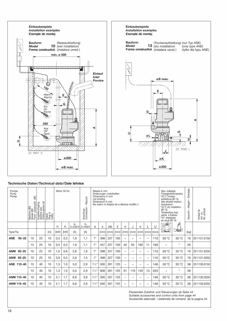
min. ø 500
A
U
ø200
øB max.
EinlaufInletPornire
Bauform Model 10Forma constructivă
(Nassaufstellung)(wet installation)(instalare umed )
(Trockenaufstellung)(dry installation)(instalare uscat )
EinbaubeispieleInstallation examplesExemple de montaj
EinbaubeispieleInstallation examplesExemple de montaj
Bauform Model 13Forma constructivă
(nur Typ ANE)(only type ANE)(tylko dla typu ANE)
AlarmAlarmy
EinOnPornit
AusOffOprit
G
E
øB max.
E
G
J
øK
ø200
øL
G
A
U
H
150
250

19
SchmutzwasserpumpenDrainage pumpsPompe pentru apa murdară
SW
2900 1/min
Capacity Q (I.G.P.M.)
Förd
erhö
he –
Sta
tic h
ead
–În
lim
ea d
e po
mpa
reH
(m)
Tota
l hea
d H
(fee
t)
Förderstrom – Delivery – Debit Q
1: SW 2 – 7 SL2: SW 3 – 8 SL3: SW 7 – 10 SL4: SW 8 – 125: SW 10 – 156: SW 20 – 13
(1-2) (3) (4-6)
Kennlinien nach EN 9906 K2Characteristic curves according to EN 9906 K2Caracteristici conform EN 9906 K2
SW

Schmutzwasserpumpen mit Mantelkühlung Typ SW
Die Umflutung des Motors mit demFördermedium sichert eine ausreichendeKühlung und schützt den Motor vorÜberhitzung auch bei extrem niedrigemWasserstand (Schlürfbetrieb).
EinsatzgebieteDie Pumpen vom Typ SW können stationär oder portabel eingesetzt werden. Sie eignen sich für Be- und Entwässerungsaufgaben in sauberem oder verschmutztemWasser, auch mit abrasiven Sand- und Schlammverunreinigungen.
Mögliche Einsätze sind:– Kellerentwässerung– Grundwasserabsenkung– Trockenhaltung von Baustellen – Entwässern von Unterführungen– Auspumpen von Schächten,
Behältern, Becken– Brauchwasserversorgung– Hochwasserschutz– Noteinsatz bei Überflutungen
Einsatzgrenzen– Kein Trockenlauf –
Überhitzungsgefahr des MotorsDie Pumpe muss minimal bis Oberkante Seiher (siehe Abmessungen; Mass «D») eingetaucht sein.
– Maximale Fördermediumtemperatur: 35 °C, kurzzeitig 60 °C
– PH Werte– für Alugussausführung: 6 – 8– für Graugussausführung: 6 – 11– für Edelstahlausführung: 2 – 11
Pompe pentru apa murdară cu răcire a mantalei tip SW
Înconjurarea motorului cu fluid asigur o r cire suficient i protejeaz motorulîmpotriva supraînc lzirii chiar i la un nivelredus al apei (func ionare cu aspirare).
Domenii de utilizarePompele de tipul SW se pot utiliza sta ionar sau portabil. Acestea suntadecvate pentru instala ii de irigare saudrenare în care se utilizeaz ap curatsau murdar , cu impurit i sub form de nisip abraziv i noroi.
Utiliz rile posibile sunt:– Drenarea pivni elor– Sc derea nivelului apei freatice– Men inerea antierelor în stare uscat – Drenarea tunelelor– Pomparea pu urilor, recipientelor,
bazinelor– Alimentarea cu ap menajer– Protec ia împotriva inunda iilor– Utilizarea de urgen la rev rs ri
Limite de utilizare– F r func ionare pe uscat –
Pericol de supraînc lzire a motoruluiPompa trebuie s fie scufundat minimum pân la marginea superioar a sitei (vezi dimensiunile; dimensiunea «D».
– Temperatura maxim a fluidului: 35 °C, 60 °C pe termen scurt
– Valoarea pH-ului– pentru construc ia din aluminiu: 6 – 8– pentru construc ia din font : 6 – 11– pentru construc ia din inox: 2 – 11
Type SW waste water pumps with jacket cooling
Flooding of the motor by the deliverymedium ensures sufficient cooling and protects the motor from overheatingeven with an extremely low water level(slurp operation).
Fields of applicationType SW pumps can be used in stationary or portable form. They are suitable for irrigation and drainage functions with clean or dirty water, also with abrasive sandand sludge contamination.
Possible fields of application:– Cellar drainage– Lowering of groundwater level– Keeping building sites dry– Drainage of subways and underpasses– Pumping out shafts, containers, basins– Supply of service water– High-water protection– Emergency application
for overflows and flooding
Limits of application– No dry running –
danger of motor overheating– Maximum delivery medium temperature:
35 °C, short-term 60 °C– The pump must be immersed at least
to upper edge of filter (see dimensions; dimension «D»).
– pH values– for cast aluminium version: 6 – 8– for cast iron version: 6 – 11– for fine steel version: 2 – 11
TypenschlüsselType designationCodul modelului
BeispielExampleExemplu
SW 7 - 10 S L
SchmutzwasserpumpeWaste water pumpPomp pentru apa murdar
Nennfördermenge in l/sNominal flowrate in l/sDebit nominal în l/s
Nennförderhöhe in mWSNominal flowrate in mWCÎn l ime de pompare nominal în mCA
Steckerfertig (plug and pump)Ready to insert (plug and pump)Preg tite de conectare (plug and pump)
Leichtbauweise (gewichtsoptimiert)Lightweight construction (weight-optimized)Construc ie u oar (greutate optimizat )
20

Eigenschaften und Lieferumfang
Portable, steckerfertige Pumpen (SL)Robuste und gewichtsoptimierte Pumpenmit angebautem Netzstecker T12 oderSchuko.– Typen SW 2-7SL/SW 3-8SL
mit aufgebautem Schwimmerschalter als Niveauregler. Pumpe funktioniert in sich automatisch.Einschaltpunkt zirka 280 mmAusschaltpunkt zirka 80 mm
– Typ SW 7-10SL für den überwachten Dauerbetrieb und mit Flachsaugmodus (durch Demontage des Saugkorbes kann das Fördermedium mit verringerter Förderleistung bis auf 5 mm abgesaugt werden).
Stationäre PumpenRobuste Pumpen mit Gewindeflansch für die Bodenaufstellung oder hängendeMontage an der Druckleitung. In Kombination mit einem Biral Steuer-gerät, den passenden Niveausensorenund Alarmgebern eine äusserst wirtschaftliche und zuverlässigeGesamtlösung.
Characteristics and scope of delivery
Portable pumps ready to insert (SL)Robust pumps of optimum weight with Storz coupling and mains plug attached T12 (IP 54).– Types SW 2-7SL/SW 3-8SL
with float switch fitted as level controller. Pump functions automatically as unit.Switch-on point approx. 280 mmSwitch-off point approx. 80 mm
– Type SW 7-10SL for monitored, continuous operation and with flat suction mode (the delivery medium can be drawn off down to 5 mm with reduced delivery capacity by dismantling the suction basket).
Stationary pumpsRobust pumps with screwed flange for floor mounting or suspension from the discharge (pressure) pipe.An extremely economical and reliableoverall solution in combination with a Biral control unit, suitable levelsensors and alarm units.
Caracteristicile şi setul livrat
Pompe portabile, pregătite pentru conectare (SL)Pompe robuste i cu greutate optimizat ,cu techer de re ea integrat T12 sauSchuko.– Tipurile SW 2-7SL/SW 3-8SL
cu flotor integrat ca regulator de nivel.Pompa func ioneaz automat.Punctul de pornire cca 280 mmPunctul de oprire cca 80 mm
– Tipul SW 7-10SL pentru func ionarea continu supravegheat i cu mod de aspirare pe suprafa (prin demontarea co ului de aspirare, fluidul poate fi aspirat cu o putere de pompare redus pân la 5 mm).
Pompe staţionarePompe robuste cu flan filetat pentruamplasarea pe podea sau montajul suspendat de conducta sub presiune. În combina ie cu dispozitivul de comandBiral, senzorii de nivel adecva i i emi to-arele de alarm , reprezint o solu ie integrat economic i fiabil .
21
SW 2-7 SL 10 x – x 1.2 0.8 5.0 10 3×1.5 x – 15 S3 x F IP 68 9 05 4784.0150
SW 2-7 SL (Schuko) 10 x – x 1.2 0.8 5.0 10 3×1.5 x – 15 S3 x F IP 68 9 05 4784.0850
SW 3-8 SL 10 x – x 1.5 1.1 6.9 10 3×1.5 x – 15 S3 x F IP 68 11 05 4784.0250
SW 3-8 SL (Schuko) 10 x – x 1.5 1.1 6.9 10 3×1.5 x – 15 S3 x F IP 68 11 05 4784.0950
SW 7-10 SL 8 x – x 1.8 1.4 8.6 20 3×1.5 x – 15 S1 x H IP 68 25 05 4784.0750
SW 7-10 SL (Schuko) 8 x – x 1.8 1.4 8.6 20 3×1.5 x – 15 S1 x H IP 68 25 05 4784.1050
SW 8-12 10 – x x 2.7 2.0 4.5 20 4×1.5 x – 15 S1 – H IP 68 49 05 4784.0450
SW 10-15 10 – x x 3.5 2.7 6.0 20 4×1.5 x – 15 S1 – H IP 68 57 05 4784.0550
SW 20-13 10 – x x 5.7 4.6 10.0 20 7×2.5 x – 15 S1 x H IP 68 66 05 4784.0650
Kug
el∅
Sp
here
∅B
il∅
1×
230
V, 5
0 H
z, ±
5%
3×
400
V, 5
0 H
z, ±
5%
2900
1 /m
in
KabelCableCablu
AnlaufStartPornire
Läng
eLe
ngth
Lung
ime
Dim
ensi
onD
imen
sion
sD
imen
siun
e
Max
. A
nläu
fe/S
tund
eM
ax. s
tart
s p
er h
our
Nr.
max
. por
niri/
or
Bet
rieb
sart
Mod
e of
op
erat
ion
Reg
im d
e op
erar
e
Wic
klun
gsch
utzk
onta
kt (W
SK
)C
oil t
herm
al p
rote
ctor
s (C
PT)
Con
tact
de
prot
ecie
a b
obin
ei (
WS
K)
Isol
atio
nskl
asse
Insu
latio
n cl
ass
Cla
sa d
e iz
olar
e
Sch
utza
rtTy
pe
of p
rote
ctio
nC
lasa
de
prot
ecie
Gew
icht
Wei
ght
Gre
utat
e
Art
ikel
-Nr.
Art
. no.
Nr.
artic
ol
Dire
kt/D
irect
/Dire
ct
P1 P2 IN Y-Δ
[mm] [kW] [kW] [A] [m] [mm2] [kg]
PumpePumpPomp
Motor
LeistungsdatenPerformance dataDate despre putere
Technische Daten/Technical data/Date tehnice
SW

20 9925.1
Werkstoffe/Materials/Materiale
SW 2-7 SL Edelstahl Edelstahl Edelstahl gummiert Edelstahl Kohlegraphit/Chromstahl NBRSW 3-8 SL Fine steel Fine steel Fine steel Fine steel Carbon graphite/chromium steel
Inox Inox Inox cauciucat Inox Grafit de c rbune/o el cromat
SW 7-10 SL Grauguss/Aluminiumguss Grauguss Edelstahl Aluminium/PVC-hart Siliciumkarbid/Siliciumkarbid NBRCast iron/cast aluminium Cast iron Fine steel Aluminium/hard-PVC Silicon carbide/silicon carbideFont gri/aluminiu Font gri Inox Aluminiu/PVC dur Carbur de siliciu/carbur de siliciu
SW 8-12 Grauguss Grauguss Edelstahl Grauguss/Edelstahl Siliciumkarbid/Siliciumkarbid NBRSW 10-15 Cast iron Cast iron Fine steel Cast iron/fine steel Silicon carbide/silicon carbide
Font gri Font gri Inox Font gri/inox Carbur de siliciu/carbur de siliciu
SW 20-13 Grauguss Hartguss Edelstahl Grauguss/Edelstahl Siliciumkarbid/Siliciumkarbid NBRCast iron Chilled iron Fine steel Cast iron/fine steel Silicon carbide/silicon carbideFont gri Font dur Inox Font gri/inox Carbur de siliciu/carbur de siliciu
Type/Tip Pumpen-/MotorgehäusePumps/motor casingCarcasa pompei/motorului
LaufradImpellerRotor
SaugsiebSuction filterSită de aspirare
Druckdeckel/AussenmantelPressure cover/external jacketCapac sub presiune/manta exterioară
GleitringdichtungFloating ring sealGarnitura inelară glisantă
ElastomereElastomersElastomer
Type/Tip Abb. A ∅ B C D ∅ E ∅ F H R ZFig. max. max.
[mm] [mm] [mm] [mm] [mm] [mm] [mm] [mm] Druckstutzen/Delivery branch /Duze de presiune
SW 2-7 SL 1 260 202 76 30 218 – 300 11/4”AG/ Storz 55 mm/Schlauchtülle/11/2” IG Storz 55 mm/hose nozzle /Storz 55 mm/man on de furtun *
SW 3-8 SL 1 260 202 76 30 218 – 300 11/4”AG/ Storz 55 mm/Schlauchtülle/11/2” IG Storz 55 mm/hose nozzle /Storz 55 mm/man on de furtun *
SW 7-10 SL 2 – 220 – 64 240 8 495 21/2”AG Storz 75 mm/Storz 75 mm/Storz 75 mm
SW 8-12 3 – 220 – 114 240 10 635 21/2”AG Flansch DN 65/Flange DN 65 /Flan DN 65
SW 10-15 3 – 220 – 114 240 10 685 21/2”AG Flansch DN 65/Flange DN 65 /Flan DN 65
SW 20-13 3 – 250 – 138 280 10 755 4”AG Flansch DN 100/Flange DN 100 /Flan DN 100
* als Option erhältlich/available as option/disponibil ca op iune
Schlauchtülle 11/2”AG – 50/52 mm Hose nozzle 11/2”AG – 50/52 mm Man on de furtun 11/2”AG – 50/52 mm 05 3775.2999
Schlauchtülle 2” IG – 50 mm Hose nozzle 2” IG – 50 mm Man on de furtun 2” IG – 50 mm 05 3775.4599
Doppelnippel 11/2” /2”AG Double nipple 11/2” /2”AG Niplu dublu 11/2” /2”AG 05 3774.2099
Kunststoffschlauch Innendurchmesser 50 mm Plastic hose internal diameter 50 mm Diametrul interior al furtunului din plastic 50 mm 05 3591.4199
Schlauchbride ∅ 45 – 60 mm Hose clip dia. 45 – 60 mm Brid furtun ∅ 45 – 60 mm 05 2351.1000
Storzkupplung Typ 55 mm mit 11/2” AG Storz coupling type 55 mm with 11/2”AG Cuplaj Storz tip 55 mm cu 11/2” AG 05 2654.1400
FW Schlauch ∅ 55 mm, mit Storz 55 mm, Länge 10 m FW hose, dia. 55 mm, with Storz 55 mm, length 10 m Furtun FW ∅ 55 mm, cu Storz 55 mm, lungime 10 m 05 2654.2200
FW Schlauch ∅ 75 mm, mit Storz 75 mm, Länge 15 m FW hose, dia. 75 mm, with Storz 75 mm, length 15 m Furtun FW ∅ 75 mm, cu Storz 75 mm, lungime 15 m 05 2654.2300
Storz Übergangskupplung Typ 55/75 mm Storz transition coupling type 55/75 mm Cuplaj Storz Suprapus tip 55/75 mm 05 2654.2100
Auslaufrohr mit Storz Kupplung Typ 75 mm Outlet pipe with Storz coupling type 75 mm Conduct de evacuare cu cuplaj Storz tip 75 mm 05 2654.2000
Zubehör/Accessories/Accesorii Art. Nr.
AbmessungenDimensionsDimensiuni
Abb. 1 Abb. 3
20 9916
Abb. 2
22
Armaturen und Steuerungen ab Seite 44Fittings and control units from page 44Robinetele şi sistemele de comandă de la pagina 44

Fäkalien- und AbwasserpumpenSewage and waste water pumpsPompe pentru fecale şi apă reziduală
FEX, FWX, FMX, FSX
23
Kennlinien nach EN 9906 K2Characteristic curves according to EN 9906 K2Caracteristici conform EN 9906 K2
Förd
erhö
he –
Sta
tic h
ead
–În
lim
ea d
e po
mpa
reH
(m)
Förderstrom – Delivery – Debit Q
FEX, FWX, FMX, FSX
Alle Pumpen sind auch in ATEX-Ausführung erhältlichAll pumps are also available in ATEX versionsToate pompele sunt disponibile i cu construc ia ATEX
FEX
/FW
X/F
MX
/FS
X

Das Wirbelrad ist im Spiralgehäusezurückgesetzt. Durch das Rotierendes Laufrades werden Feststoffeunterhalb der Hydraulik auf-gewirbelt, zusammen mit demAbwasser im Spiralgehäusebeschleunigt und am Laufrad vorbei gefördert. Durch dieseEigenschaft ist diese Hydraulikideal zum Fördern von Medien mit langfasrigen Stoffen (geringesVerstopfungsrisiko).
The whirl impeller is set back in the spiral casing. Rotation of the impeller causessolid matter under the hydraulics to be whirled up, accelerated with the waste water in the spiralcasing and fed past the impeller.This characteristic makes the hydraulics ideal for pumping media with long-fibred components (little risk of blockage).
Elicea este a ezat în partea dejos în carcasa în spiral . Prin rotirearotorului, substan ele solide de sub sistemul hidraulic sunt dispersate, sunt accelerate în carcasa în spiral împreun cu aparezidual i sunt transportate din-colo de rotor. Prin aceast caracte-ristic , acest sistem hidraulic esteideal pentru pomparea fluidelor cu substan e cu fibrelungi (risc redus de obturare).
Das geschlossene, halbaxialeKanalrad erreicht durch seineBauform einen hohen Wirkungs-grad. Dadurch ist es ideal beigrossen Fördermengen, Medienmit Feststoffanteilen, Regen-,Kühl- oder Brauchwasser sowiefür Anwendungen mit langen Laufzeiten.
Ein Mehrkanalrad mit vor- gelagertem Zerkleinerungssystemzermahlt zuverlässig alle schneid-baren Feststoffe. Abwasser-entsorgung mit geringem Rohr-leitungsdurchmesser (ab 11/2”),grossen Förderhöhen bei relativgeringer Fördermenge, Druck-entwässerung in topographischschwierigen Gebieten sind typische Einsatzgebiete.Ungeeignet ist dieses System für sandhaltige Medien.
A multi-channel wheel with preceding reduction system reliably crushes all solid matterthat can be cut. Waste water disposal with small pipe diameter(from 11/2”), high delivery headswith relatively low flowrate and pressure drainage in topo-graphically difficult terrain are typical fields of application. This system is unsuitable for media containing sand.
O roat cu mai multe canale, cu sistem de tocare pe aspira iem run e te fiabil toate substan elesolide care pot fi t iate. Eliminareaapei reziduale cu un diametru mical conductei (de la 11/2”), cu în l imide pompare mari la un debit relativ mic, drenarea sub presiuneîn zone dificile din punct de vedere topografic reprezintdomenii de utilizare tipice. Acest sistem nu este adecvat pentru fluide cu con inut de nisip.
Nassaufstellung mit automatischemKupplungssystem (Bf 11)Die Pumpe wird an einer Stahlkettean den Gleitrohren in den Schachtabgesenkt und automatisch am fest installierten Kupplungsfussangedockt. Im Servicefall kann die Pumpegehoben werden, ohne in denSchacht absteigen zu müssen.
Wet installation with automaticcoupling system (Mod. 11)The pump is lowered into the shaft (manhole) on a steelchain on the slides and dockedautomatically on the permanentlyinstalled coupling elbow.The pump can be raised for servicing without having to descend into the shaft.
Amplasarea umedă cu sistem automat de cuplare (Bf 11)Pompa este coborât pe un landin o el, pe evile de glisare în pui este racordat automat la piciorul de cuplare instalat fix. În caz de service, pompa este ridicat f r a trebui s se coboareîn pu .
Nassaufstellung mit Bodenstützring (Bf 12)Diese Aufstellvariante eignet sichprimär für temporäre Installation(z.B. Bauprovisorium). Der Montageaufwand ist gering,dafür sind Abstriche bei allfälligenServicearbeiten hinzunehmen.
Trockenaufstellung in horizontaleroder vertikaler Ausführung, mit Mediumskühlung oder externem Kühlkreislauf sind auf Anfrage erhältlich.
The design of the enclosed, semi-axial channel wheel ensureshigh efficiency. It is thereforeideal for high flowrates, mediawith solid matter content, rainwater, cooling water or service water and for applicationswith long running times.
Wet installation with groundsupport ring (Mod. 12)This installation version is mainlysuitable for temporary installations(e.g. provisional structures). The installation costs are low, butomissions have to be expected in possible servicing work.
Dry installation for horizontal or vertical version, with cooling of the medium or external coolingcircuit available on request.
Roata cu canal închis , semi-axial atinge un randamentmare prin aceast form constructiv . Astfel, este idealpentru debite mari, fluide cu con inut de substan e solide, apa de ploaie, de r cire sau mena-jer , precum i pentru aplica ii cudurat de func ionare mare.
Amplasarea umedă cu inel de susţinere a bazei (Bf 12)Aceast variant de amplasare este adecvat în primul rând pentru instalarea temporar (de ex. construc ie provizorie). Costul de montaj este redus, dar trebuie luate în calcul posibile omisiuni în cazul lucr rilor de service.
La cerere este disponibil amplasarea pe uscat pentru construc ia orizontal sau vertical cu r cirea cu fluid sau circuit de r cire extern.
24
Hydraulischer Aufbau Hydraulic construction Construcţie hidraulică
Bauformen Construction versions Forme constructive
Type/Tip FWX
Type//Tip FEX
Type/Tip FMX/FSX

Verwendungszweck– Fördermedium: Klar-, Schmutzwasser,
Abwasser und Fäkalien mit kurzfasrigen (FWX auch langfasrige) Feststoffen und Schlamm mit organischen Materialien (Kugeldurchgang beachten).
– PH-Wert: 5–11– Maximale Dichte des Fördermediums:
1.1 kg/dm3
– Maximaler Feststoffanteil: 5%– Temperatur des Fördermediums:
35 °C, kurzzeitig 60 °C– Maximale Eintauchtiefe: 10 m
Einsatzgebiete
Eigenschaften– Drehstrommotor: 3× 400 V, 50 Hz– Isolationsklasse: H (max. 180 °C)– Schutzart: IP 68– Kabellänge: 10 m– Motoranschluss:
vorbereitet für Direktstart (DOL), ab einer Leistung P1 ≥ 4 kW für den Stern-Dreieck Anlauf (Y-Δ)
– Tauglich für Sanftstart-Betrieb– Teilweise tauglich für den Betrieb
mit Frequenzumformer (FU) (Details siehe technische Daten)
– Geräuschpegel: <70 dB(A)– Wicklungsschutzkontakt:
In der Motorenwicklung eingebaute Temperaturfühler. Auslösetemperatur 132 °C
– Doppelte Gleitringdichtung:Zwei Gleitringdichtungen mit dazwischenliegender Ölsperrkammer trennen optimal das Fördermedium vom Motor.
– Dichtungssensor (OSK): Ein Sensor erkennt das Eindringen von Fördermedium in die Ölsperr-kammer. So bleibt genügend Zeit für eine Revision, bevor der Motor beschädigt wird.
Purpose– Pumped medium: clear, contaminated
water, waste water and sewage with solid matter and sludge with organic substances (observe sphere passage).
– pH value: 5–11– Maximum density of pumped medium:
1.1 kg/dm3
– Maximum solid content: 5%– Temperature of pumped medium:
35 °C, short-term 60 °C– Maximum immersion depth: 10 m
Fields of application
Scopul utilizării– Fluid: Ap clar , ap murdar , ap
rezidual i fecale cu substan e solide cu fibre scurte (FWX i cu fibre lungi) i noroi cu materiale organice (aten ie la orificiul pentru bil ).
– Valoarea pH-ului: 5–11– Densitatea maximă a fluidului:
1,1 kg/dm3
– Cantitatea maximă de substanţe solide: 5%– Temperatura fluidului:
35 °C, 60 °C pe termen scurt– Adâncimea maximă de imersie: 10 m
Domenii de utilizare
25
Characteristics– Three-phase motor: 3× 400 V, 50 Hz– Insulation class: H (max. 180 °C)– Protection class: IP 68– Cable length: 10 m– Motor connection:
Prepared for direct starting (DOL), from a power P1 ≥ 4 kW for star-delta starting (Y-Δ)
– Suitable for soft start operation– Partly suitable for operation
with frequency converter (FU)(for details see technical data)
– Noise level: <70 dB(A)– Winding protection contact:
Temperature sensor fitted in the motor winding (operating temperature >132 °C).
– Double floating ring seal:Two floating ring seals with intermediateoil barrier chamber provide optimum separation of pumped medium and motor.
– Sealing sensor (OSK):A sensor detects the penetration of pumped medium in the oil barrier chamber. There is therefore sufficient time for an overhaul before the motor suffers any damage.
Caracteristici– Motor trifazat: 3× 400 V, 50 Hz– Clasa de izolare: F (max. 180 °C)– Clasa de protecţie: IP 68– Lungimea cablului: 10 m– Racordul motorului:
preg tit pentru pornire direct (DOL), de la o putere P1 ≥ 4 kW pentru pornirea stea-triunghi (Y-Δ)
– Adecvat pentru func ionarea cu pornire soft
– Adecvat par ial pentru func ionarea cu convertizor de frecven (FU) (Pentru detalii, vezi datele tehnice)
– Nivelul de zgomot: <70 dB(A)– Contact de protecţie a bobinei:
Senzor de temperatur integrat în bobina motorului. Temperatura de declan are 132 °C
– Etanşare mecanică dublă:Dou etan ri mecanice cu camer inter-mediar de blocare a uleiului ce asigur o separare optim a fluidul de motor.
– Senzor de etanşeitate (OSK): Un senzor detecteaz p trunderea fluidului în camera de blocare a uleiului. Astfel r mâne suficient timp pentru revizie, înainte ca motorul s fie deteriorat.
FEX 80 < 75 x x xFEX 80 ≥ 80 x x x x x x x x x x xFWX 80 < 75 x x xFWX 80 ≥ 80 x x x x x x x x x x xFEX 100 ≥ 100 x x x x x x x xFWX100 x x x x x x x xFEX 150 ≥ 100 x x x x x xFMX 50 – x x x
Kug
eld
urch
gang
in m
mS
phe
re s
ize
in m
mO
rific
iu p
entr
u bi
l în
mm
Ein
fam
ilien
haus
Priv
ate
hom
eC
as p
entr
u o
fam
ilie
klei
nes
Meh
rfam
ilien
haus
Sm
all a
par
tmen
t b
lock
Blo
c m
ic p
entru
mai
mul
te fa
mili
i
grös
sere
s M
ehrf
amili
enha
usLa
rge
apar
tmen
t b
lock
Bloc
mar
e pe
ntru
mai
mul
te fa
milii
Woh
nüb
erb
auun
gR
esid
entia
l dev
elop
men
tB
loc
de lo
cuin
e
War
enha
usD
epar
tmen
t st
ore
Dep
ozit
Cam
pin
g
Res
taur
ant
Gew
erb
liche
Ob
jekt
eC
omm
erci
al p
rem
ises
Obi
ectiv
e co
mer
cial
e
Sp
ital
Hos
pita
lS
pita
l
Öffe
ntlic
he E
inric
htun
gP
ublic
fac
ility
Inst
ituie
pub
lic
Dru
cken
twäs
seru
ngP
ress
ure
dra
inag
eD
rena
re s
ub p
resi
une
Entw
ässe
rung
abg
eleg
ene
Geb
iete
Dra
inag
e of
rem
ote
area
sD
rena
rea
zone
lor
izol
ate
Reg
enw
asse
rent
sorg
ung
Rai
nwat
er d
isp
osal
Elim
inar
ea a
pei p
luvi
ale
Grundsatz:Je unkontrollierbarer der Benutzerkreis, desto grösser sollte der Kugeldurchgang gewählt werden.
Principle:The less controllable the range of users, the larger the sphere passage that should be selected.
Premis :Cu cât utilizatorii sunt mai greu de controlat, cu atât mai mare trebuie s se selecteze orificiulpentru bil .
FEX
/FW
X/F
MX
/FS
X

FWX 80 - 230 / 4 026
Betriebsart– Dauerbetrieb (S1) mit untergetauchtem
Motor.– Aussetzbetrieb (S3) mit komplett
aufgetauchtem Motor(Der Aussetzbetrieb setzt sich aus Intervallen von 10 Minuten Dauer zusammen.z. B.: S3 = 30 %, bedeutet 3 Minuten Betrieb und 7 Minuten Pause.)
Werkstoffe:Motorengehäuse: Grauguss
(EN-GJL-250)Pumpengehäuse: Grauguss
(EN-GJL-250)Laufrad: Grauguss
(EN-GJL-250)Schleissring bei Kanalradpumpen: Bronze Motorenwelle/Schrauben: EdelstahlKühlmantel: EdelstahlGleitringdichtungen: Siliziumkarbid/
SiliziumkarbidElastomere: NBRKabel: H07RN-F (PLUS)Zerkleinerungs- Edelstahl 1.4122system: (55 HRC)
Mode of operation– Continuous operation (S1)
with motor submersed.– Intermittent operation (S3*)
with motor fully emerged(Intermittent operation consists of intervals of 10 minutes duration, e.g. S3 = 30% means 3 minutes operation and 7 minutes interval.)
Materials:Motor casing: cast iron
(EN-GJL-250)Pump casing: cast iron
(EN-GJL-250)Impeller wheel: cast iron
(EN-GJL-250)Wear ring in channelimpeller pumps: bronzeMotor shaft/screws: Stainless steelCooling jacket: Stainless steelFloating ring seals: silicon carbide/
silicon carbideElastomers: NBRCable: H07RN-F (PLUS)Reduction system: high-grade steel
1.4122 (55 HRC)
Regim de funcţionare– Func ionare continu (S1) cu motor
imersat.– Func ionare intermitent (S3) cu motor
complet imersat(Func ionarea intermitent S3 presupune intervale de câte 10 minute.de ex.: S3 = 30 %, înseamn 3 minute func ionare i 7 minute pauz .)
Materiale:Carcasa motorului: Font gri
(EN-GJL-250)Carcasa pompei: Font gri
(EN-GJL-250)Rotor: Font gri
(EN-GJL-250)Inel de uzură la pompele cu roată cu canal: Bronz Arborele motorului/Şuruburi: InoxManta de răcire: InoxEtanşări mecanice: Carbur de siliciu/
Carbur de siliciuElastomer: NBRCablu: H07RN-F (PLUS)Tocător: Inox 1.4122
(55 HRC)
TypenschlüsselType designationCodul modelului
Typenreihe (siehe Seite 24)Series (see page 24)Seria (vezi pagina 24)
Druckstutzenabmessung in [DN]Pressure branch dimensions in [DN]Dimensiunea duzelor de presiune în [DN]
Laufraddurchmesser in [mm]Impeller rated diameter [mm]Diametrul rotorului în [mm]
Motorenpolzahl (2 = 2900 1/min, 4 = 1450 1/min, 6 = 960 1/min)Number of motor poles(2 = 2900 1/min, 4 = 1450 1/min, 6 = 960 1/min)Num rul polilor motorului (2 = 2900 1/min, 4 = 1450 1/min, 6 = 960 1/min)
Motorenleistung P2 (026 = 2,6 kW)Motor power P2 (026 = 2,6 kW)Puterea motorului P2 (026 = 2,6 kW)
26

Druckanschluss: Pressure connection: Racord sub presiune: DN 80/3”Laufrad: Impeller: Rotor:Wirbel-/Einkanalrad Whirl/single-channel Girante a vortice/
impeller a un canaleKugeldurchgang: Sphere size: Orificiu pentru bil : 50-62 mmWeitere Informationen More information Alte informa iiSeite Page Pagina 28
FWX 80FEX 80
FWX 80
FWX 80FEX 80
FEX 100FEX 150
FMX 50FSX 50
Druckanschluss: Pressure connection: Racord sub presiune: DN 100Laufrad: Impeller: Rotor:Wirbelrad Whirl impeller Elice
Kugeldurchgang: Sphere size: Orificiu pentru bil : 100Weitere Informationen More information Alte informa iiSeite Page Pagina 32
FWX 100
Druckanschluss: Pressure connection: Racord sub presiune: DN 80Laufrad: Impeller: Rotor:Wirbelrad Whirl impeller EliceKugeldurchgang: Sphere size: Orificiu pentru bil : 80 mmWeitere Informationen More information Alte informa iiSeite Page Pagina 29
Druckanschluss: Pressure connection: Racord sub presiune: AG 2”/DN 50Laufrad: Impeller: Rotor:Zerkleinerungs- Reduction system Sistem de tocaresystemKugeldurchgang: Sphere size: Orificiu pentru bil : –Weitere Informationen More information Alte informa iiSeite Page Pagina 33
Druckanschluss: Pressure connection: Racord sub presiune: DN 80Laufrad: Impeller: Rotor:Wirbel-/Einkanalrad Whirl/single-channel Elice/
impeller roată cu un canalKugeldurchgang: Sphere size: Orificiu pentru bil : 80 mmWeitere Informationen More information Alte informa iiSeite Page Pagina 30
Druckanschluss: Pressure connection: Racord sub presiune: DN 100/150Laufrad: Impeller: Rotor:Einkanalrad Single-channel Roată cu un canal
impellerKugeldurchgang: Sphere size: Orificiu pentru bil : 100 mmWeitere Informationen More information Alte informa iiSeite Page Pagina 31+32
27
FEX
/FW
X/F
MX
/FS
X

B C H L
Nr. Type/Tip DN [mm] [mm] [mm] [mm]
1 FWX 80-160/4 010 DN 80 (3” AG) 186 518 232 296
2 FWX 80-170/4 018 DN 80 (3” AG) 169 572 258 294
3 FEX 80-114/2 018 DN 80 (3” AG) 186 518 232 296
4 FEX 80-124/2 021 DN 80 (3” AG) 186 518 232 296
5 FEX 80-128/2 032 DN 80 (3” AG) 186 555 232 296
FWX 80 FEX 80
28 * Erläuterung Seiten 25/26/Explanation pages 25/26 /Explica ia la paginile 25/26
[mm] [1/min] [kW] [kW] [A] [%] [kg] Standard
1 FWX 80-160/4 010 50 1450 1.3 1.0 2.7 15 30 - x 40 05 4775.0180
2 FWX 80-170/4 018 62 1450 2.3 1.8 5.0 15 30 - x 40 05 4775.0280
3 FEX 80-114/2 018 50 2900 2.3 1.8 3.8 15 30 - x 40 05 4775.0380
4 FEX 80-124/2 021 50 2900 2.6 2.1 4.5 15 30 - x 40 05 4775.0480
5 FEX 80-128/2 032 50 2900 3.8 3.2 6.5 15 30 - x 45 05 4775.0580
Erhältlich in explosionsgeschützter Ausführung:/Available in explosion-proof version: /Disponibil în construc ia cu protec ie împotriva exploziilor: ATEX II 2G Ex c d (e)(ib) IIB T4
Kug
el∅
Sp
here
∅B
il∅
Dre
hzah
lS
pee
dTu
raie
Gew
icht
Wei
ght
Gre
utat
e
P1Nr. Type/Tip P2 IN Sta
rt/h
S3* FU* OSK*
Artikel-Nr.Art. no.Nr. articol
MotorBetriebsartMode of operationRegim de functionare

B C H L
Nr. Type/Tip DN [mm] [mm] [mm] [mm]
1 FWX 80-170/4 013 DN 80 220 526 290 365
2 FWX 80-180/4 013 DN 80 220 526 290 365
3 FWX 80-220/4 026 DN 80 250 563 316 408
4 FWX 80-230/4 026 DN 80 250 563 316 408
5 FWX 80-227/4 037 DN 80 250 694 316 408
6 FWX 80-232/4 050 DN 80 250 767 316 408
FWX 80
29* Erläuterung Seiten 25/26/Explication aux pages 25/26 /Explica ia la paginile 25/26
Artikel-Nr.Art. no.Nr. articol
[mm] [1/min] [kW] [kW] [A] [%] [kg] Standard
1 FWX 80-170/4 013 80 1450 1.7 1.3 3.3 15 30 - x 64 05 4775.2080
2 FWX 80-180/4 013 80 1450 1.7 1.3 3.3 15 30 - x 64 05 4775.2180
3 FWX 80-220/4 026 80 1450 3.4 2.6 6.2 15 30 - x 67 05 4775.2280
4 FWX 80-230/4 026 80 1450 3.4 2.6 6.2 15 30 - x 67 05 4775.2380
5 FWX 80-227/4 037 80 1450 4.4 3.7 7.5 15 30 - x 90 05 4775.2480
6 FWX 80-232/4 050 80 1450 5.9 5.0 9.9 15 30 - x 90 05 4775.2580
Erhältlich in explosionsgeschützter Ausführung:/Available in explosion-proof version: /Disponibil în construc ia cu protec ie împotriva exploziilor: ATEX II 2G Ex c d (e)(ib) IIB T4
Kug
el∅
Sp
here
∅B
il∅
Dre
hzah
lS
pee
dTu
raie
Gew
icht
Wei
ght
Gre
utat
e
P1Nr. Type/Tip P2 IN Sta
rt/h
S3* FU* OSK*
MotorBetriebsartMode of operationRegim de functionare
FEX
/FW
X/F
MX
/FS
X

[mm] [1/min] [kW] [kW] [A] [%] [kg] Standard
1 FWX 80-170/2 064 80 2900 7.5 6.4 13.0 15 25 x x 91 05 4775.4080
2 FWX 80-175/2 095 80 2900 11.0 9.5 18.8 15 25 x x 103 05 4775.4180
3 FWX 80-185/2 095 80 2900 11.0 9.5 18.8 15 25 x x 103 05 4775.4280
4 FWX 80-195/2 115 80 2900 13.1 11.5 22.2 15 25 x x 108 05 4775.4380
5 FEX 80-180/2 144 80 2900 16.0 14.4 27.0 15 25 x x 181 05 4775.4680
6 FEX 80-195/2 196 80 2900 22.0 19.6 36.9 15 25 x x 191 05 4775.4580
Erhältlich in explosionsgeschützter Ausführung:/Available in explosion-proof version: /Disponibil în construc ia cu protec ie împotriva exploziilor: ATEX II 2G Ex c d (e)(ib) IIB T4
B C H L
Nr. Type/Tip DN [mm] [mm] [mm] [mm]
1 FWX 80-170/2 064 DN 80 220 694 290 365
2 FWX 80-175/2 095 DN 80 220 767 290 365
3 FWX 80-185/2 095 DN 80 220 767 290 365
4 FWX 80-195/2 115 DN 80 220 767 290 365
5 FEX 80-180/2 144 DN 80 200 830 307 355
6 FEX 80-195/2 196 DN 80 200 830 307 355
30
FWX 80 FEX 80
Kug
el∅
Sp
here
∅B
il∅
Dre
hzah
lS
pee
dTu
raie
Gew
icht
Wei
ght
Gre
utat
e
P1Nr. Type/Tip P2 IN Sta
rt/h
S3* FU* OSK*
MotorBetriebsartMode of operationRegim de functionare
* Erläuterung Seiten 25/26/Explanation pages 25/26 /Explica ia la paginile 25/26
Artikel-Nr.Art. no.Nr. articol
B C H L
Nr. Type/Tip DN DNS [mm] [mm] [mm] [mm]
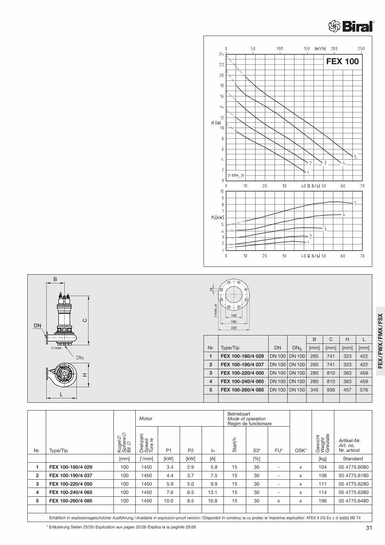
1 FEX 100-180/4 029 DN 100 DN 100 265 741 323 422
2 FEX 100-190/4 037 DN 100 DN 100 265 741 323 422
3 FEX 100-220/4 050 DN 100 DN 100 280 810 363 459
4 FEX 100-240/4 065 DN 100 DN 100 280 810 363 459
5 FEX 100-260/4 085 DN 100 DN 150 345 936 457 576
31
FEX 100
* Erläuterung Seiten 25/26/Explication aux pages 25/26 /Explica ia la paginile 25/26
[mm] [1/min] [kW] [kW] [A] [%] [kg] Standard
1 FEX 100-180/4 029 100 1450 3.4 2.9 5.8 15 30 - x 104 05 4775.6080
2 FEX 100-190/4 037 100 1450 4.4 3.7 7.5 15 30 - x 108 05 4775.6180
3 FEX 100-220/4 050 100 1450 5.9 5.0 9.9 15 30 - x 111 05 4775.6280
4 FEX 100-240/4 065 100 1450 7.6 6.5 13.1 15 30 - x 114 05 4775.6380
5 FEX 100-260/4 085 100 1450 10.0 8.5 16.8 15 30 x x 196 05 4775.6480
Erhältlich in explosionsgeschützter Ausführung:/Available in explosion-proof version: /Disponibil în construc ia cu protec ie împotriva exploziilor: ATEX II 2G Ex c d (e)(ib) IIB T4
Kug
el∅
Sp
here
∅B
il∅
Dre
hzah
lS
pee
dTu
raie
Gew
icht
Wei
ght
Gre
utat
e
P1Nr. Type/Tip P2 IN Sta
rt/h
S3* FU* OSK*
MotorBetriebsartMode of operationRegim de functionare
FEX
/FW
X/F
MX
/FS
X
Artikel-Nr.Art. no.Nr. articol

FWX 100
B C H L
Nr. Type/Tip DN DNS [mm] [mm] [mm] [mm]
1 FWX 100-202/4 050 DN 100 DN 100 280 799 336 460
2 FWX 100-212/4 050 DN 100 DN 100 280 799 336 460
3 FWX 100-212/4 065 DN 100 DN 100 280 799 336 460
4 FWX 100-222/4 065 DN 100 DN 100 280 799 336 460
5 FWX 100-222/4 085 DN 100 DN 150 280 914 336 460
6 FWX 100-232/4 085 DN 100 DN 150 280 914 336 460
7 FWX 100-232/4 122 DN 100 DN 150 280 974 336 460
* Erläuterung Seiten 25/26/Explanation pages 25/26 /Explica ia la paginile 25/26
[mm] [1/min] [kW] [kW] [A] [%] [kg] Standard
1 FWX 100-202/4 050 100 1450 5.9 5.0 9.9 15 30 x x 123 05 4775.7080
2 FWX 100-212/4 050 100 1450 5.9 5.0 9.9 15 30 x x 123 05 4775.7180
3 FWX 100-212/4 065 100 1450 7.6 6.5 13.1 15 30 x x 126 05 4775.7280
4 FWX 100-222/4 065 100 1450 7.6 6.5 13.1 15 30 x x 126 05 4775.7380
5 FWX 100-222/4 085 100 1450 10.0 8.5 16.8 15 30 x x 152 05 4775.7480
6 FWX 100-232/4 085 100 1450 10.0 8.5 16.8 15 30 x x 152 05 4775.7580
7 FWX 100-232/4 122 100 1450 14.0 12.2 23.0 15 30 x x 152 05 4775.7680
Erhältlich in explosionsgeschützter Ausführung:/Available in explosion-proof version: /Disponibil în construc ia cu protec ie împotriva exploziilor: ATEX II 2G Ex c d (e)(ib) IIB T4
Kug
el∅
Sp
here
∅B
il∅
Dre
hzah
lS
pee
dTu
raie
Gew
icht
Wei
ght
Gre
utat
e
P1Nr. Type/Tip P2 IN Sta
rt/h
S3* FU* OSK*
MotorBetriebsartMode of operationRegim de functionare
32
Artikel-Nr.Art. no.Nr. articol

FWX 100
B C H L
Nr. Type/Tip DN DNS [mm] [mm] [mm] [mm]
8 FWX 100-262/4 122 DN 100 DN 150 345 1008 410 555
9 FWX 100-272/4 122 DN 100 DN 150 345 1008 410 555
10 FWX 100-272/4 146 DN 100 DN 150 345 1008 410 555
11 FWX 100-282/4 146 DN 100 DN 150 345 1008 410 555
12 FWX 100-282/4 193 DN 100 DN 150 345 1098 410 555
13 FWX 100-292/4 146 DN 100 DN 150 345 1008 410 555
14 FWX 100-292/4 193 DN 100 DN 150 345 1098 410 555
* Erläuterung Seiten 25/26/Explication aux pages 25/26 /Explica ia la paginile 25/26
[mm] [1/min] [kW] [kW] [A] [%] [kg] Standard
8 FWX 100-262/4 122 100 1450 14.0 12.2 23.0 15 30 x x 205 05 4775.7780
9 FWX 100-272/4 122 100 1450 14.0 12.2 23.0 15 30 x x 205 05 4775.7880
10 FWX 100-272/4 146 100 1450 17.0 14.6 28.8 15 30 x x 205 05 4775.7980
11 FWX 100-282/4 146 100 1450 17.0 14.6 28.8 15 30 x x 205 05 4775.8080
12 FWX 100-282/4 193 100 1450 21.9 19.3 39.1 15 30 x x 227 05 4775.8180
13 FWX 100-292/4 146 100 1450 17.0 14.6 28.8 15 30 x x 205 05 4775.8280
14 FWX 100-292/4 193 100 1450 21.9 19.3 39.1 15 30 x x 227 05 4775.8380
Erhältlich in explosionsgeschützter Ausführung:/Available in explosion-proof version: /Disponibil în construc ia cu protec ie împotriva exploziilor: ATEX II 2G Ex c d (e)(ib) IIB T4
Kug
el∅
Sp
here
∅B
il∅
Dre
hzah
lS
pee
dTu
raie
Gew
icht
Wei
ght
Gre
utat
e
P1Nr. Type/Tip P2 IN Sta
rt/h
S3* FU* OSK*
MotorBetriebsartMode of operationRegim de functionare
33
FEX
/FW
X/F
MX
/FS
X
Artikel-Nr.Art. no.Nr. articol

B C H L
Nr. Type/Tip DN DNS [mm] [mm] [mm] [mm]
1 FEX 150-340/6 073 DN 150 DN 150 420 1016 547 690
2 FEX 150-370/6 100 DN 150 DN 150 420 1016 547 690
3 FEX 150-300/4 146 DN 150 DN 150 370 996 468 608
4 FEX 150-310/4 193 DN 150 DN 150 370 1086 468 608
5 FEX 150-340/4 220 DN 150 DN 150 420 1201 547 690
34
FEX 150
* Erläuterung Seiten 25/26/Explanation pages 25/26 /Explica ia la paginile 25/26
[mm] [1/min] [kW] [kW] [A] [%] [kg] Standard
1 FEX 150-340/6 073 100 960 9.0 7.3 16.3 15 30 x x 272 05 4775.6580
2 FEX 150-370/6 100 100 960 12.0 10.0 22.4 15 30 x x 297 05 4775.6680
3 FEX 150-300/4 146 100 1450 17.0 14.6 28.8 15 30 x x 229 05 4775.6780
4 FEX 150-310/4 193 100 1450 21.9 19.3 39.1 15 30 x x 248 05 4775.6880
5 FEX 150-340/4 220 100 1450 25.0 22.0 44.0 15 30 x x 388 05 4775.6980
Erhältlich in explosionsgeschützter Ausführung:/Available in explosion-proof version: /Disponibil în construc ia cu protec ie împotriva exploziilor: ATEX II 2G Ex c d (e)(ib) IIB T4
Kug
el∅
Sp
here
∅B
il∅
Dre
hzah
lS
pee
dTu
raie
Gew
icht
Wei
ght
Gre
utat
e
P1Nr. Type/Tip P2 IN Sta
rt/h
S3* FU* OSK*
MotorBetriebsartMode of operationRegim de functionare
Artikel-Nr.Art. no.Nr. articol
B C C1 H L L1
Nr. Type/Tip DN [mm] [mm] [mm] [mm] [mm] [mm]
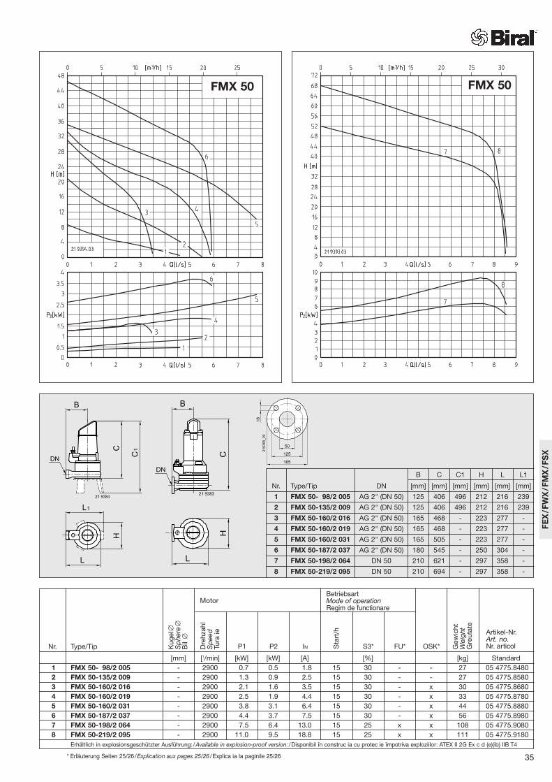
1 FMX 50- 98/2 005 AG 2" (DN 50) 125 406 496 212 216 239
2 FMX 50-135/2 009 AG 2" (DN 50) 125 406 496 212 216 239
3 FMX 50-160/2 016 AG 2" (DN 50) 165 468 - 223 277 -
4 FMX 50-160/2 019 AG 2" (DN 50) 165 468 - 223 277 -
5 FMX 50-160/2 031 AG 2" (DN 50) 165 505 - 223 277 -
6 FMX 50-187/2 037 AG 2" (DN 50) 180 545 - 250 304 -
7 FMX 50-198/2 064 DN 50 210 621 - 297 358 -
8 FMX 50-219/2 095 DN 50 210 694 - 297 358 -
35
FMX 50 FMX 50
* Erläuterung Seiten 25/26/Explication aux pages 25/26 /Explica ia la paginile 25/26
[mm] [1/min] [kW] [kW] [A] [%] [kg] Standard1 FMX 50- 98/2 005 - 2900 0.7 0.5 1.8 15 30 - - 27 05 4775.84802 FMX 50-135/2 009 - 2900 1.3 0.9 2.5 15 30 - - 27 05 4775.85803 FMX 50-160/2 016 - 2900 2.1 1.6 3.5 15 30 - x 30 05 4775.86804 FMX 50-160/2 019 - 2900 2.5 1.9 4.4 15 30 - x 33 05 4775.87805 FMX 50-160/2 031 - 2900 3.8 3.1 6.4 15 30 - x 44 05 4775.88806 FMX 50-187/2 037 - 2900 4.4 3.7 7.5 15 30 - x 56 05 4775.89807 FMX 50-198/2 064 - 2900 7.5 6.4 13.0 15 25 x x 108 05 4775.90808 FMX 50-219/2 095 - 2900 11.0 9.5 18.8 15 25 x x 111 05 4775.9180
Erhältlich in explosionsgeschützter Ausführung:/Available in explosion-proof version: /Disponibil în construc ia cu protec ie împotriva exploziilor: ATEX II 2G Ex c d (e)(ib) IIB T4
Kug
el∅
Sp
here
∅B
il∅
Dre
hzah
lS
pee
dTu
raie
Gew
icht
Wei
ght
Gre
utat
e
P1Nr. Type/Tip P2 IN Sta
rt/h
S3* FU* OSK*
MotorBetriebsartMode of operationRegim de functionare
FEX
/FW
X/F
MX
/FS
X
Artikel-Nr.Art. no.Nr. articol

36
FSX Biral-Tauchmotorpumpe mit Schneideinrichtung
Verwendungszweck:Fördermedium:– Zum Fördern von häuslichem Abwasser
und Fäkalien, auch mit groben und faserigen Bestandteilen.
– Max. Temperatur des Fördermediums:40 °C
Eigenschaften:– Bauart:
Einstufiges Blockaggregat für den transportablen sowie stationären Einsatz.
– Hydraulik:Pumpengehäuse mit horizontalem Druckanschluss G 2 AG.Einstellbares Mehrschaufelrad mit vorgeschalteter Schneideinrichtungzur Zerkleinerung von Feststoffen.
– Wellendichtung:Drehrichtungsunabhängige Kombinationvon Gleitringdichtung und Radial-dichtung in Ölsperrkammer.
– Wellenlagerung:Robuste, wartungsfreie, dauergeschmierte Wälzlager.
– Motor:Druckwasserdichter Elektromotor mit 2-poliger Wicklung.Isolationsklasse der Wicklung F,Schutzart IP 68.
– Motorkühlung:Motor mit Oberflächenkühlung im Tauchbetrieb.
– Betriebsart:Motor untergetaucht: Dauerbetrieb (S1)Motor aufgetaucht: Kurzzeitbetrieb (S3)oder Aussetzbetrieb (S3), siehe technische Daten.
– Technische Daten:Spannung: 400 VStartart: DirektDruckanschluss: G 2 AG
– Werkstoffe:Motorgehäusedeckel: Kunststoff PP-GFMotorgehäuse: Edelstahl 1.4301Pumpengehäuse: Grauguss EN-GJL-250Laufrad: Edelstahl 1.4308Schneideinrichtung: Edelstahl 1.4122Motorwelle: Edelstahl 1.4104Mechanische Verbindungsteile: EdelstahlO-Ringe: NBRGleitringdichtung (mediumseitig): SiC/SiCWellendichtring (motorseitig): NBROberlager: Rillenkugellager
– Lieferumfang:Länge Anschlusskabel: 10 mAnschlusskabel mit Schutzhülle
FSX Biral submersible pump with cutter
Intended purpose:Pumped fluid:– For pumping household waste water
and sewage, also with coarse and fibrous materials.
– Maximum temperature of the pumped fluid: 40 °C
Specification:– Type:
Single-stage close-coupled design for both portable and stationary applications.
– Hydraulics:Pump housing with horizontal pressure connection G 2 AG.Adjustable multivane impeller with upstream cutting device for macerating solids.
– Shaft seal:Combination of bi-rotational floating ring seal and radial seal in oil barrier chamber.
– Shaft bearing:Robust, maintenance-free, permanently lubricated bearings.
– Motor:Fully submersible electric motor with two-pole winding.Winding insulation class F,Ingress protection IP 68
– Motor cooling:Motor with surface cooling in immersed operation
– Mode of operation:Motor submersed: Continuous operation S1Motor non-immersed: Short-term operation (S3) or intermittent operation (S3), see Technical Data.
– Technical Data:Voltage: 400 VStarting type: DirectPressure connection G 2 AG
– Materials:Motor housing cover: Plastic (PP-GF)Motor casing: Stainless steel 1.4301Pump casing: Grey cast iron EN-GJL-250Impeller: Stainless steel 1.4308Cutter: Stainless steel 1.4122Motor shaft: Stainless steel 1.4104Mechanical connecting parts: Stainless steelO-rings: NBRFloating ring seal (fluid side): SiC/SiCShaft seal (motor side): NBRUpper bearing: Deep-groove ball bearing
– Scope of delivery:Length of connection cable: 10 mConnection cable with protective sleeve
Pompă cu motor imersabil FSX Biral cu dispozitiv de tăiere
Scopul utilizării:Fluid:– Pentru pomparea apei reziduale
menajere i a fecalelor, de asemenea, cu componente mari i cu fibre lungi.
– Temperatura max. a fluidului: 40 °C
Caracteristici:– Tip constructiv:
Agregat bloc cu o singur treapt pentru utilizare transportabil i sta ionar .
– Sistem hidraulic:Carcasa pompei cu racord sub presiune orizontal G 2 AG.Roat setabil cu mai multe lope i cu dispozitiv de t iere montat în amonte pentru m run irea substan elor solide.
– Garnitura arborelui:Combina ie în func ie de direc ia de rota ie dintre etan area mecanic i garnitura radial în camera de blocare a uleiului.
– Lagărele arborelui:Lag re robuste, f r între inere, lubrifiate permanent:
– Motor:Electromotor etan la apa sub presiune cu bobin cu 2 poli.Clasa de izolare a bobinei F,clasa de protec ie IP 68.
– Răcirea motorului:Motor cu r cirea suprafe ei la func ionarea cu imersie.
– Regim de operare:Motor imersat: func ionare continu (S1)Motor la suprafa : func ionare de scurt durat (S3) sau func ionare intermitent (S3), vezi datele tehnice.
– Date tehnice:Tensiune: 400 VTip de pornire: directRacord sub presiune: G 2 AG
– Materiale:Capacul carcasei motorului: plastic PP-GFCarcasa motorului: o el inoxidabil 1.4301Carcasa pompei: font gri EN-GJL-250Rotor: o el inoxidabil 1.4308Dispozitiv de t iere: o el inoxidabil 1.4122Arbore motor: o el inoxidabil 1.4104Piese mecanice de leg tur : InoxGarnituri inelare: NBREtan are mecanic (pe circuitul fluidului): SiC/SiCGarnitura arborelui (pe circuitul motorului): NBRLag r superior: rulment radial cu bile
– Setul livrat:Lungime cablu de racordare: 10 mCablu de racordare cu man on de protec ie

37
FSX 50
[mm] [1/min] [kW] [kW] [A] [%] [kg] Standard
1 FSX 50-155/2 012 – 2900 1.5 1.2 2.5 15 50 – – 19 05 4775.9480
Kug
el∅
Sp
here
∅B
il∅
Dre
hzah
lS
pee
dTu
raie
Gew
icht
Wei
ght
Gre
utat
e
P1Nr. Type/Tip P2 IN Sta
rt/h
S3* FU* OSK
MotorBetriebsartMode of operationRegim de functionare
FEX
/FW
X/F
MX
/FS
X
EinschaltniveauActivation levelNivel de pornire 490-540 mmAusschaltniveauShut-off levelNivel de oprire 220-270 mm
142
DN 2” AG 393
473
117
211
248
Artikel-Nr.Art. no.Nr. articol

350 min.
G
S
J
X
DN Q
60
V
O
R
N
F
K
2200
min
.
219374_00
AlarmAlarmeAlarm
AusDéclenchéOff
EinEnclenchéOn
Y Z
219370_00
W
S
T2
1
1
70
60
219369_00
W2
40 H
40
MM1
M2
270
Z min.
30
L
L1
200
200
340
min
.
30
E
219373_00
40 H
40
270
200
200
340
min
.
30
LZ min.
L1
30
200
200
M3
M4
M5
M6
EE
219372_00
FEX/FWXSchachteinbauPit installationMontarea în puţ
Schachtabdeckung für 2 PumpenShaft (manhole) cover for 2 pumpsCapacul puţului pentru 2 pompe
Schachtabdeckung für 1 PumpeShaft (manhole) cover for 1 pumpCapacul puţului pentru 1 pompă
Befestigung KupplungsfussFixing of coupling elbowFixarea piciorului cuplajului
Befestigung EnddistanzstückFixing of end spacerFixarea piesei finale
Y
Befestigung WandankerFixing of wall anchorAncoră de perete pentru fixare
Z
38
Ein
lauf
/Inl
et/A
dm
isie
BaugrösseSizeDimensiunea constructivă
H L L1 M3 M4 M5 M6 Z min
[mm] [mm] [mm] [mm] [mm] [mm] [mm] [mm]
III 764 704 844 1079 1139 1219 573 400
IV 1064 1004 1144 1479 1539 1619 773 425
BaugrösseSizeDimensiunea constructivă
H L L1 M M1 M2 Z min
[mm] [mm] [mm] [mm] [mm] [mm] [mm]
I 764 704 844 506 566 646 400
II 1064 1004 1144 706 766 846 425
AlarmAlarmeAlarm
EINONPORNIT
AUSOFFOPRIT

39
Einbaumasse mit automatischem Kupplungssystem (Bauform 11)Installation dimensions with automatic coupling system (construction version 11)Dimensiunea de montaj cu sistem automat de cuplare (forma de construcţie 11)
Type/Tip DN E F G J K N O Q R S S1 T T1 T2 W W1 W2 V X
[mm] [mm] [mm] [mm] [mm] [mm] [mm] [mm] [mm] [mm] [mm] [mm] [mm] [mm] [mm] [mm]
FEX 80-114/2 018 DN 80 (3”) 232 320 190 173 367 402 142 417 2” 156 260 110 110 - M16 M 10 M 8 102 644 I / III
FEX 80-124/2 021 DN 80 (3”) 232 320 190 173 367 402 142 417 2” 156 260 110 110 - M16 M 10 M 8 102 644 I / III
FEX 80-128/2 032 DN 80 (3”) 232 320 190 173 367 402 142 444 2” 156 260 110 110 - M16 M 10 M 8 102 644 I / III
FEX 80-180/2 144 DN 80 307 320 190 173 419 461 142 844 2” 156 260 110 110 - M16 M 10 M 8 102 703 I / III
FEX 80-195/2 196 DN 80 307 320 190 173 399 461 142 737 2” 156 260 110 110 - M16 M 10 M 8 102 703 I / III
FEX 100-180/4 029 DN 100 323 415 240 200 461 531 200 618 11/2” 240 60 200 270 60 M16 M 12 M 8 87 846 I / III
FEX 100-190/4 037 DN 100 323 415 240 200 461 531 200 618 11/2” 240 60 200 270 60 M16 M 12 M 8 87 846 I / III
FEX 100-220/4 050 DN 100 363 415 240 200 474 568 200 680 11/2” 240 60 200 270 60 M16 M 12 M 8 87 883 I / III
FEX 100-240/4 065 DN 100 363 415 240 200 474 568 200 680 11/2” 240 60 200 270 60 M16 M 12 M 8 87 883 I / III
FEX 100-260/4 085 DN 100 457 415 240 200 541 685 200 797 11/2” 240 60 200 270 60 M16 M 12 M 8 87 1000 II / IV
FEX 150-340/6 073 DN 150 547 450 275 280 657 817 280 878 2” 340 100 300 400 100 M16 M 12 M 8 110 1239 II / IV
FEX 150-370/6 100 DN 150 547 450 275 280 657 817 280 878 2” 340 100 300 400 100 M16 M 12 M 8 110 1239 II / IV
FEX 150-300/4 146 DN 150 468 450 275 280 607 735 280 861 2” 340 100 300 400 100 M16 M 12 M 8 110 1158 II / IV
FEX 150-310/4 193 DN 150 468 450 275 280 607 735 280 951 2” 340 100 300 400 100 M16 M 12 M 8 110 1158 II / IV
FEX 150-340/4 220 DN 150 547 450 275 280 657 817 280 1063 2” 340 100 300 400 100 M16 M 12 M 8 110 1239 II / IV
FWX 80-160/4 010 DN 80 (3”) 232 320 190 173 367 402 142 417 2” 156 260 110 110 - M16 M 10 M 8 102 644 I / III
FWX 80-170/4 018 DN 80 (3”) 258 320 190 173 352 399 142 443 2” 156 260 110 110 - M16 M 10 M 8 102 642 I / III
FWX 80-170/4 013 DN 80 290 320 190 173 419 471 142 448 2” 156 260 110 110 - M16 M 10 M 8 102 713 I / III
FWX 80-180/4 013 DN 80 290 320 190 173 419 471 142 448 2” 156 260 110 110 - M16 M 10 M 8 102 713 I / III
FWX 80-220/4 026 DN 80 316 320 190 173 449 514 142 485 2” 156 260 110 110 - M16 M 10 M 8 102 756 I / III
FWX 80-230/4 026 DN 80 316 320 190 173 449 514 142 485 2” 156 260 110 110 - M16 M 10 M 8 102 756 I / III
FWX 80-227/4 037 DN 80 316 320 190 173 449 514 142 504 2” 156 260 110 110 - M16 M 10 M 8 102 756 I / III
FWX 80-232/4 050 DN 80 316 320 190 173 449 514 142 577 2” 156 260 110 110 - M16 M 10 M 8 102 756 I / III
FWX 80-170/2 064 DN 80 290 320 190 173 419 471 142 616 2” 156 260 110 110 - M16 M 10 M 8 102 713 I / III
FWX 80-175/2 095 DN 80 290 320 190 173 419 471 142 689 2” 156 260 110 110 - M16 M 10 M 8 102 713 I / III
FWX 80-185/2 095 DN 80 290 320 190 173 419 471 142 689 2” 156 260 110 110 - M16 M 10 M 8 102 713 I / III
FWX 80-195/2 115 DN 80 290 320 190 173 419 471 142 689 2” 156 260 110 110 - M16 M 10 M 8 102 713 I / III
FWX 100-202/4 050 DN 100 336 415 240 200 541 569 200 699 11/2” 240 60 200 270 60 M16 M 12 M 8 872 884 I / III
FWX 100-212/4 050 DN 100 336 415 240 200 541 569 200 699 11/2” 240 60 200 270 60 M16 M 12 M 8 87 884 I / III
FWX 100-212/4 065 DN 100 336 415 240 200 541 569 200 699 11/2” 240 60 200 270 60 M16 M 12 M 8 87 884 I / III
FWX 100-222/4 065 DN 100 336 415 240 200 541 569 200 699 11/2” 240 60 200 270 60 M16 M 12 M 8 87 884 I / III
FWX 100-222/4 085 DN 100 336 415 240 200 541 569 200 814 11/2” 240 60 200 270 60 M16 M 12 M 8 87 884 I / III
FWX 100-232/4 085 DN 100 336 415 240 200 541 569 200 814 11/2” 240 60 200 270 60 M16 M 12 M 8 87 884 I / III
FWX 100-232/4 122 DN 100 336 415 240 200 541 569 200 874 11/2” 240 60 200 270 60 M16 M 12 M 8 87 884 I / III
FWX 100-262/4 122 DN 100 410 415 240 200 541 664 200 898 11/2” 240 60 200 270 60 M16 M 12 M 8 87 979 II / IV
FWX 100-272/4 122 DN 100 410 415 240 200 541 664 200 898 11/2” 240 60 200 270 60 M16 M 12 M 8 87 979 II / IV
FWX 100-272/4 146 DN 100 410 415 240 200 541 664 200 898 11/2” 240 60 200 270 60 M16 M 12 M 8 87 979 II / IV
FWX 100-282/4 146 DN 100 410 415 240 200 541 664 200 898 11/2” 240 60 200 270 60 M16 M 12 M 8 87 979 II / IV
FWX 100-282/4 193 DN 100 410 415 240 200 541 664 200 988 11/2” 240 60 200 270 60 M16 M 12 M 8 87 979 II / IV
FWX 100-292/4 146 DN 100 410 415 240 200 541 664 200 898 11/2” 240 60 200 270 60 M16 M 12 M 8 87 979 II / IV
FWX 100-292/4 193 DN 100 410 415 240 200 541 664 200 988 11/2” 240 60 200 270 60 M16 M 12 M 8 87 979 II / IV
Sch
acht
abde
ckun
g/G
röss
eM
anho
le c
over
ing/
Size
Cap
acul
pu
ului
/dim
ensi
une
FEX
/FW
X/F
MX
/FS
X

60
DN
K
2200
min
.
G F
S
J Q
350 min.
O
V
X
N
219181_01
AlarmAlarmeAlarm
AusDéclenchéOff
EinEnclenchéOn
Y Z
R
Ein
lauf
/Inl
et/A
dm
isie
FMXSchachteinbauPit installationMontarea în puţ
70
60
219369_00
W2
40 H
40
MM1
M2
270
Z min.
30
L
L1
200
200
340
min
.
30
E
219373_00
40 H
40
270
200
200
340
min
.
30
LZ min.
L1
30
200
200
M3
M4
M5
M6
EE
219372_00
Schachtabdeckung für 2 PumpenShaft (manhole) cover for 2 pumpsCapacul puţului pentru 2 pompe
Schachtabdeckung für 1 PumpeShaft (manhole) cover for 1 pumpCapacul puţului pentru 1 pompă
Befestigung KupplungsfussFixing of coupling elbowFixarea piciorului cuplajului
Befestigung EnddistanzstückFixing of end spacerFixarea piesei finale
Y
Befestigung WandankerFixing of wall anchorAncoră de perete pentru fixare
Z
BaugrösseSizeDimensiunea constructivă
H L L1 M3 M4 M5 M6 Z min
[mm] [mm] [mm] [mm] [mm] [mm] [mm] [mm]
III 764 704 844 1079 1139 1219 573 400
IV 1064 1004 1144 1479 1539 1619 773 425
BaugrösseSizeDimensiunea constructivă
H L L1 M M1 M2 Z min
[mm] [mm] [mm] [mm] [mm] [mm] [mm]
I 764 704 844 506 566 646 400
II 1064 1004 1144 706 766 846 425
40
Type/Tip DN E F G J K N O Q R S S1 T T1 T2 W W1 W2 V X
[mm] [mm] [mm] [mm] [mm] [mm] [mm] [mm] [mm] [mm] [mm] [mm] [mm] [mm] [mm] [mm]
FMX 50-160/2 016 2” (DN 50) 223 250* 160 60 210 358 90 491 1/2” 80 35 118 118 - M 12 M 8 M 8 45 504 I / III
FMX 50-160/2 019 2” (DN 50) 223 250* 160 60 210 358 90 491 1/2” 80 35 118 118 - M 12 M 8 M 8 45 504 I / III
FMX 50-160/2 031 2” (DN 50) 223 250* 160 60 210 358 90 526 1/2” 80 35 118 118 - M 12 M 8 M 8 45 504 I / III
FMX 50-187/2 037 2” (DN 50) 250 250* 160 60 210 391 90 568 1/2” 80 35 118 118 - M 12 M 8 M 8 45 533 I / III
FMX 50-198/2 064 DN 50 297 300 190 170 385 478 170 600 11/2” 210 60 270 270 60 M16 M 12 M 8 87 732 I / III
FMX 50-219/2 095 DN 50 297 300 190 170 385 478 170 672 11/2” 210 60 270 270 60 M16 M 12 M 8 87 732 I / III
219370_00
W
S
T2
1
1
GrösseSizeDimensiune
AlarmAlarmeAlarm
EINONPORNIT
AUSOFFOPRIT

Abb./Fig. 1 Abb./Fig. 2
Type/Tip Abb./Fig. DN A E P R U Z[mm] [mm] [mm] [mm] [mm] [mm]
FEX 80-114/2 018 2 DN 80 101 232 518 301 230 518 I / III
FEX 80-124/2 021 2 DN 80 101 232 518 301 230 518 I / III
FEX 80-128/2 032 2 DN 80 101 232 555 301 230 518 I / III
FEX 80-180/2 144 2 DN 80 218 307 1062 418 395 620 I / III
FEX 80-195/2 196 2 DN 80 218 307 955 418 395 620 I / III
FEX 100-180/4 029 2 DN 100 248 323 866 468 395 724 I / III
FEX 100-190/4 037 2 DN 100 248 323 866 468 395 724 I / III
FEX 100-220/4 050 2 DN 100 255 363 935 475 395 739 I / III
FEX 100-240/4 065 2 DN 100 255 363 935 475 395 739 I / III
FEX 100-260/4 085 2 DN 100 260 457 1061 480 450 831 II / IV
FEX 150-340/6 073 2 DN 150 263 547 1141 483 450 1055 II / IV
FEX 150-370/6 100 2 DN 150 263 547 1141 483 450 1055 II / IV
FEX 150-300/4 146 2 DN 150 260 468 1121 480 450 973 II / IV
FEX 150-310/4 193 2 DN 150 260 468 1211 480 450 973 II / IV
FEX 150-340/4 220 2 DN 150 312 547 1375 532 600 1085 II / IV
FMX 50- 98/2 005 1 IG 2” 133 185 496 235 212 359 I / III
FMX 50-135/2 009 1 IG 2” 133 185 496 235 212 359 I / III
FMX 50-160/2 016 1 IG 2” 191 223 618 293 350 460 I / III
FMX 50-160/2 019 1 IG 2” 191 223 618 293 350 460 I / III
FMX 50-160/2 031 1 IG 2” 191 223 655 293 350 460 I / III
FMX 50-187/2 037 1 IG 2” 193 250 695 295 350 475 I / III
FMX 50-198/2 064 2 DN 50 193 297 771 326 410 633 I / III
FMX 50-219/2 095 2 DN 50 193 297 848 326 410 633 I / III
FWX 80-160/4 010 2 DN 80 101 232 518 301 230 518 I / III
FWX 80-170/4 018 2 DN 80 129 258 572 329 250 516 I / III
FWX 80-170/4 013 2 DN 80 203 290 651 403 395 640 I / III
FWX 80-180/4 013 2 DN 80 203 290 651 403 395 640 I / III
FWX 80-220/4 026 2 DN 80 203 316 688 403 395 670 I / III
FWX 80-230/4 026 2 DN 80 203 316 688 403 395 670 I / III
FWX 80-227/4 037 2 DN 80 203 316 819 403 395 670 I / III
FWX 80-232/4 050 2 DN 80 203 316 892 403 395 670 I / III
FWX 80-170/2 064 2 DN 80 203 290 819 403 395 640 I / III
FWX 80-175/2 095 2 DN 80 203 290 892 403 395 640 I / III
FWX 80-185/2 095 2 DN 80 203 290 892 403 395 640 I / III
FWX 80-195/2 115 2 DN 80 203 290 892 403 395 640 I / III
FWX 100-202/4 050 2 DN 100 225 336 924 445 395 739 I / III
FWX 100-212/4 050 2 DN 100 225 336 924 445 395 739 I / III
FWX 100-212/4 065 2 DN 100 225 336 924 445 395 739 I / III
FWX 100-222/4 065 2 DN 100 225 336 924 445 395 739 I / III
FWX 100-222/4 085 2 DN 100 225 336 1039 445 395 739 I / III
FWX 100-232/4 085 2 DN 100 225 336 1039 445 395 739 I / III
FWX 100-232/4 122 2 DN 100 225 336 1099 445 395 739 I / III
FWX 100-262/4 122 2 DN 100 235 410 1133 455 450 831 I / III
FWX 100-272/4 122 2 DN 100 235 410 1133 455 450 831 I / III
FWX 100-272/4 146 2 DN 100 235 410 1133 455 450 831 I / III
FWX 100-282/4 146 2 DN 100 235 410 1133 455 450 831 I / III
FWX 100-282/4 193 2 DN 100 235 410 1223 455 450 831 I / III
FWX 100-292/4 146 2 DN 100 235 410 1133 455 450 831 I / III
FWX 100-292/4 193 2 DN 100 235 410 1223 455 450 831 I / III
Sch
acht
abde
ckun
g/G
röss
eM
anho
le c
over
ing/
Size
Cap
acul
pu
ului
/dim
ensi
une
Einbaumasse mit Bodenstützring (Bauform 12)Installation dimensions with floor support ring (construction form 12)Dimensiunea de montaj cu inel de susţinere a bazei (forma de construcţie 12)
41
FEX
/FW
X/F
MX
/FS
X

ZubehörAccessoriesAccesoriile
Pos Bezeichnung Dimension Art. Nr.Item Designation Dimensions Art. no.Poz. Denumire Dimensiune Nr art.
1 Kupplungsfuss R 2” 21 2646.0100Coupling elbow DN 50 21 2647.0100Picior cuplaj DN 80 21 2608.0100
DN 100 21 2644.0100DN 150 21 2645.0100
1 Kupplungsfuss DN 80 für Betonnormschachteinbau (NS..)Coupling elbow DN 80for concrete standard shaft fitting (NS..)Picior cuplaj DN 80 pentru montajul în pu ul normal din beton (NS..) 21 2608.0200
2 Kupplungsflansch R 2” 21 2668.0100Coupling flange DN 50 21 2672.0100Flan cuplaj DN 80 21 2638.0100
DN 100DN 150
3 End-Distanzstück für Wand- R 2” 21 2652.0100und Deckenmontage DN 50 21 2653.0100End spacer for ceiling DN 80 21 2636.0100and wall mounting DN 100 21 2654.0100Distan ier final DN 150 21 2655.0100pentru montajul pe perete Weitere Varianten auf Anfrage
Further versions on requestAlte variante la cerere
4 Stützfuss zu/to/pentru FMX 50-160 05 4776.3010Supporting foot zu/to/pentru FMX 50-187 05 4776.3011Picior de sus inere zu/to/pentru FMX 50-198 / -219 05 4776.3006
DN 80/DN 100 05 4776.3007DN 150 (P2 bis/up to/pân la 16.9 kW) 05 4776.3008DN 150 (P2 ab/from/de la 17.0 kW) 05 4776.3009
5 Rohrbogen 90° IG 2” - IG 2” 05 3707.0858Pipe elbow 90° DN 50 - DN 50 21 2687.0180Cot 90° DN 80 - DN 80 21 2641.0180
DN 100 - 100 21 2642.0180DN 150 - DN 150 21 2643.0180
6 Ablasskette mit 2 Schäkel max. 300 kg, 1 m (V4A) 21 1939.2000Lowering chain max. 300 kg, 3 m (V4A) 21 1939.2150with 2 shackles max. 300 kg, 6 m (V4A) 21 1939.2250Lan de evacuare max. 300 kg, × m (V4A) 05 2899.0529cu 2 toarte+2× Schäkel/chain/toarteKette/Chain/Lan max. 450 kg, 3 m (V4A) 21 1939.2450
max. 450 kg, 6 m (V4A) 05 2899.0729 +2× Schäkel/chain/toarte max. 450 kg, × m (V4A) 05 2899.1129
Weitere Varianten auf AnfrageFurther versions on requestAlte variante la cerere
42

SchachtabdeckungShaft coverCapacul puţului
Bezeichnung Dimension Art. Nr.Designation Dimensions Art. no.Denumire Dimensiune Nr art.
Schachtabdeckung 0.5 t Traglastfür 1-Pumpen-Anlage Loading capacity/Sarcină portantăShaft cover Abdeckplatte (Grösse I)for 1-pump system Cover plate (size l)Capacul pu ului Plac de acoperire (dimensiunea I) 21 1970.0100pentru instala ia cu 1 pomp Rahmen (Grösse I)
Frame (size l)Cadru (dimensiunea I) 21 1971.0100Abdeckplatte (Grösse II)Cover plate (size lI)Plac de acoperire (dimensiunea II) 21 1988.0100Rahmen (Grösse II)Frame (size lI)Cadru (dimensiunea II) 21 1986.0100
1.0 t Traglast Loading capacity/Sarcină portantăAbdeckplatte (Grösse I)Cover plate (size l)Plac de acoperire (dimensiunea I) 21 2213.0100Rahmen (Grösse I)Frame (size l)Cadru (dimensiunea I) 21 1971.0100
3.0 t TraglastLoading capacity/Sarcină portantăAbdeckplatte (Grösse I)Cover plate (size l)Plac de acoperire (dimensiunea I) 21 2355.0100Rahmen (Grösse I)Frame (size l)Cadru (dimensiunea I) 21 1971.0100
Schachtabdeckung 0.5 t Traglastfür 2-Pumpen-Anlage Loading capacity/Sarcină portantăShaft cover 2× Abdeckplatte (Grösse III)for 2-pump system 2× Cover plate (size lII)Capacul pu ului 2× Plac de acoperire (dimensiunea III) 21 1970.0100pentru instala ia cu 2 pompe Rahmen (Grösse III)
Frame (size lII)Cadru (dimensiunea III) 21 1993.01002× Abdeckplatte (Grösse IV)2× Cover plate (size lV)2× Plac de acoperire (dimensiunea IV) 21 1988.0100Rahmen (Grösse IV)Frame (size lV)Cadru (dimensiunea IV) 21 2021.0100
1.0 t TraglastLoading capacity/Sarcină portantă2× Abdeckplatte (Grösse III)2× Cover plate (size lII)2× Plac de acoperire (dimensiunea III) 21 2213.0100Rahmen (Grösse III)Frame (size lII)Cadru (dimensiunea III) 21 2356.0100
3.0 t Traglast Loading capacity/Sarcină portantă2× Abdeckplatte (Grösse III)2× Cover plate (size lII)2× Plac de acoperire (dimensiunea III) 21 2355.0100Rahmen (Grösse III)Frame (size lII)Cadru (dimensiunea III) 21 2356.0100
43
FEX
/FW
X/F
MX
/FS
X

ArmaturenFittingsRobinete
Flachschieber Flat slide valve Robinet platTyp 50 aus Messing Type 50 of brass Tip 50 din alamBetriebsdruck working pressure Presiune de func ionaremax. 10 bar max. 10 bar max. 10 barIG 1/2” 05 2801.0600IG 3/4” 05 2801.0800IG 1” 05 2801.1000IG 11/4” 05 2801.1200IG 11/2” 05 2801.1400IG 2” 05 2801.1600IG 21/2” 05 2801.1800IG 3” 05 2801.1900
Kugelhahn Ball valve Robinet sferă
Typ 12 Type 12 Tip 12aus Messing vernickelt from nickel-plated brass din alam nichelatBetriebsdruck working pressure Presiune de func ionaremax. 10 bar max. 10 bar max. 10 barIG 1/2” 05 2894.1500IG 3/4” 05 2894.1600IG 1” 05 2894.1700IG 11/4” 05 2894.1800IG 11/2” 05 2894.1900IG 2” 05 2894.2000IG 21/2” 05 2894.2100
Rückschlagklappe Flap check valve Clapă de refularemit Weichdichtung with soft seal cu garnitur moaleTyp 80A aus Messing Type 80A of brass Tip 80A din alamBetriebsdruck working pressure Presiune de func ionaremax. 10 bar max. 10 bar max. 10 barIG 1” 05 2867.1600IG 11/4” 05 2867.1700IG 11/2” 05 2867.1800IG 2” 05 2867.1900IG 21/2” 05 2867.2000
Kugelrückschlag- Non-return Clapet de sensventil ball valve cu bilăTyp 508 Type 508 Tip 508Epoxy beschichtet epoxy coated Acoperit cu r in epoxidicBetriebsdruck working pressure Presiune de func ionaremax. 10 bar max. 10 bar max. 10 barIG 1” 05 2821.8400IG 11/4” 05 2821.8500IG 11/2” 05 2821.8600IG 2” 05 2821.8700IG 21/2” 05 2821.8800
44

Rückschlagklappe Non-return flap valve Clapă de refularemit Hebel with lever cu manet i greutateund Schliessgewicht and locking weight pentru închidereBetriebsdruck working pressure Presiune de func ionaremax. 10 bar max. 10 bar max. 10 barAusführung: Version: Construc ie:Typ KAT 15 60-A type KAT 15 60-A Tip KAT 15 60-Amit Kunstharz- with synthetic resin cu vopsea lichidFlüssiglackierung liquid enamelling pe baz de r in
sinteticDN 65, PN 16 05 2821.4400DN 80, PN 16 05 2821.3900DN 100, PN 16 05 2821.4000DN 125, PN 16 05 2821.4100DN 150, PN 16 05 2821.4200DN 200, PN 10 05 2821.4300
Ausführung: Version: Construc ie:Typ 7226 verzinkt type 7226 galvanized Tip 7226 zincatDN 65, PN 16 05 2821.2740DN 80, PN 16 05 2821.3740DN 100, PN 16 05 2821.3840DN 125, PN 16 05 2821.3040DN 150, PN 16 05 2821.3140
Kugelrückschlag- Non-return Clapet de sensventil ball valve cu bilăTyp 408 type 408 Tip 408Epoxy beschichtet epoxy coated Acoperit cu r in epoxidicBetriebsdruck working pressure Presiune de func ionaremax. 10 bar max. 10 bar max. 10 barDN 65, PN 10 05 2821.9200DN 80, PN 10 05 2821.9900DN 100, PN 10 05 2821.9700DN 125, PN 10 05 2821.8300DN 150, PN 10 05 2821.8000DN 200, PN 10 05 2821.9300
ArmaturenFittingsRobinete
Flachschieber Flat slide valve Împingător platmit Weichdichtung with soft seal cu garnitur moale Betriebsdruck working pressure Presiune de func ionaremax. 10 bar max. 10 bar max. 10 barAusführung: Version: Construc ie:Typ 142 grundiert type 142 primary coated Tip 142 grunduitDN 65, PN 16 05 2805.0500DN 80, PN 16 05 2805.0300DN 100, PN 16 05 2805.0400DN 125, PN 16 05 2805.0800DN 150, PN 16 05 2805.0900DN 200, PN 16 05 2805.1000
Ausführung: Version: Construc ie:Typ 142 type 142 Tip 142Rilsan beschichtet Rilsan coated Acoperit cu RilsanDN 65, PN 16 05 2805.0540DN 80, PN 16 05 2805.0340DN 100, PN 16 05 2805.0440DN 125, PN 16 05 2805.0840DN 150, PN 16 05 2805.0940
45
Arm
atur
en

46

SteuergeräteControl devicesDispozitive de comandă
BS
BS 5319
BS 5279
✔ ✔
✔ ✔
✔ ✔
78 19.09.07 16.45
186 h2.4 A
h
h
A
782 h.. .
Schacht füllenFill shaftUmplere pu
Pumpe einPump onPompa pornit
Anlage InformationSystem informationInforma ii despre instala ie
47
✔ ✔
BS

Steuergerät für 1 PumpeBS 5279Steuergerät für 2 PumpenBS 5319
Eine Steuerung ist mehr als nur einSchaltkasten um eine Pumpe «ein» und«aus» zu schalten. Sie ist Schnittstelle zwischen dem Menschen (Bediener) und der Maschine (Pumpe). Dieser Tatsache haben wir hoheBeachtung geschenkt. Die neue Steuerung «sagt» demBetreiber, Service- und Unterhalts-personal was sich im Pumpenschachtabspielt und teilt dies mit einem grafischen Display und im Text mit.
Control devices for 1 pumpBS 5279Control devices for 2 pumpsBS 5319
A control device is more than just a boxfor switching a pump «on» and «off». It forms the interface between the man(operator) and the machine (pump).Considerable attention has been paid to this fact. The new control device «tells» the operator or service and maintenance personnel what is happening in the pump shaft and indicates this situationwith a graphic display and text.
Dispozitiv de comandă pentru 1 pompăBS 5279Dispozitiv de comandă pentru 2 pompeBS 5319
Un sistem de comand este mai multdecât o caset de conexiuni pentru «pornirea» i «oprirea» pompei. Acesta este o interfa între om (utilizator) i ma in (pomp ). Am acordat mult aten ie acestui fapt. Noul sistem de comand îi «spune» utilizatorului, personalului de service i de între inere ce se întâmpl în pu ulpompei i comunic acest lucru cu unafi aj grafic i prin text.
EinsatzbereichDie Steuerung wird hauptsächlich für das Entleeren von Schächten, Grubenund Behältern im Zusammenspiel miteiner oder zwei Pumpen verwendet. Die Niveauregulierung kann wahlweiseüber den digitalen Eingang mitSchwimmerschalter/Elektroden oder über einen optional erhältlichen Analog-Eingang mit Drucksensor realisiert werden.
EinsatzgrenzeDie Steuerung darf nicht im explosivenBereich (ATEX) montiert werden.
Ihr Nutzen– Einfache und intuitive Bedienung.– Einfache Installation und benutzer-
freundliches Anschliessen der Kabel, dank steckbaren Anschlussklemmen, kein Platzmangel.
– Hohe Anlagensicherheit und frühzeitige Erkennung von Fehlfunktionen, dank permanentem Schwimmer, Überwachung und Notbetrieb, damit Havarien vermieden werden können.
– Einfachste Lokalisierung von Störungs-ursachen durch Fehlermeldung in Text und Grafik – kein zeitraubendes Entschlüsseln von Fehlercodes und Blinksignalen.
– Optimiertes Gesamtpaket – viele Funktionen sind im Standard integriert und müssen nicht kostspielig dazugekauft werden.
Domeniul de utilizareSistemul de comand se utilizeaz în principal pentru golirea pu urilor, a pivni elor i a recipientelor împreun cu una sau dou pompe. Reglarea nivelului se poate realize la alegere prin intrarea digital cuflotor/electrozi sau printr-o intrare analogic op ional cu sensor de presiune.
Limita de utilizareSistemul de comand nu trebuie s fiemontat în zone explozive (ATEX).
Avantajele sale– Utilizare simpl i intuitiv .– Instalare simpl i racordare u oar a
cablului, datorit bornelor de conectare racordabile, f r limitare a spa iului.
– Siguran sporit a instala iei i recunoa tere timpurie a defec iunilor, datorit flotorului permanent, supraveghere i func ionare de urgen , pentru a se putea evita avariile.
– Localizare simpl a cauzelor avariilor prin semnalarea erorilor cu text i grafic
– f r decodare anevoioas a codurilor de eroare i a semnalelor prin iluminare intermitent .
– Pachet complet optimizat – numeroase func ii sunt integrate în versiunea standard i nu trebuie achizi ionate suplimentar.
Range of applicationThe control device is mainly used for draining shafts, pits and containers in conjunction with one or two pumps.Level control can be provided as requiredvia the digital input with float switch/electrodes or with an analogue input with pressure sensor, available as anoption.
Limits of applicationThe control device must not be mountedin areas subject to explosion (ATEX).
Your benefit– Simple and intuitive operation.– Easy installation and user-friendly
cable connection with plug-in connecting terminals, no shortage of space.
– High system reliability and early detection of malfunctions by means of permanent float switch, monitoring and standby operation, to reliable prevention of damage.
– Simplest possible fault-finding by error message in text and graphics – no time-consuming decoding of error codes and flashing signals.
– Optimized overall package – many functions are provided as standard and do not have to be purchased later at extra cost.
48

49
LeistungsmerkmalePerformance featuresCaracteristici de putere
Technische DatenTechnical dataDatele tehnice
Wicklungsschutzkontakt Winding protection contact Contact de protec ie Standard Option(WSK) (WSK) a bobinei (WSK)
Ölsperrkammer- Oil barrier chamber monitor Supravegherea camereiüberwachung de blocare a uleiului
Betriebsstrommessung Operating current M surarea curentului measurement de func ionare
Steuersignal-Auswertung Control signal evaluation Evaluarea semnalului de comand
Steuerspannungs- Control voltage monitor Supravegherea tensiuniiüberwachung de comand
Fehlerspeicher Error memory Memorarea erorilor
Motorschützüberwachung Motor protection monitor Supravegherea protec ieimotorului
Betriebs-/ Operating message/ Mesaj de func ionare/Sammelstörmeldung Collective fault message de eroare colectivpotentialfrei zero potential liber de poten ial(max. 230 VAC/1 A) (max. 230 VAC/1 A) (max. 230 VAC/1 A)
Optischer/akustischer Optical/acoustic alarm Emi tor de alarm Alarmgeber (230 VAC/1 A) optic /acustic(230 VAC/1 A) (230 VAC c.a./1 A)
Externer Ein/Aus External on/off Pornire/oprire externSchaltkontakt switch contact Contact de comutare
Potentialfreie Kontakte Zero potential contacts Contacte libere de poten ialfür Zentralleitsystem for central control system pentru sistemul de control
centralizat
Nachlauf Run-on Func ionare ulterioar
Zwangslauf Forced running Func ionare for at
Notbetrieb Standby operation Func ionare de urgen(automatisch/manuell) (automatic/manual) (automat/manual)
Betriebsstundenzähler Operating hours counter Contorul orelor de func ionare
Analoger Steuereingang Analogue control input Intrare de comand analogic
Alternierender Betrieb Alternating operation Func ionare alternativ(BS 5319) (BS 5319) (BS 5319)
Grafik Display Graphic display Afi aj grafic65×40 mm, 200×128 Pixel 65×40 mm, 200×128 pixels 65×40 mm, 200×128 pixeli
Einspeisung- Control voltage input Tensiune de alimentare Steuerspannung 230 VAC 230 V c.a.230 VAC
Steuerleistungsbedarf Control energy demand Necesar de putere max. 10 W max. 10 W pentru comand max 10 W
Steuerung Control device Comand für Wandmontage for wall mounting pentru montajul pe perete(B×H×T: 200×300×140/ (w× h× d: 200×300×140/ (l×Î×A: 200×300×140/
300×300×190 300×300×190 300×300×190)500×400×210) 500×400×210) 500×400×210)
Signalspannung Signal voltage Tensiune de semnal24 VDC 24 VDC 24 V c.c.
Schaltleistungen Switching capacities Capacit i de conectare0,37-18,5 kW bei 3×400 VAC 0,37-18,5 kW at 3×400VAC 0,37-18,5 kW la 3×400 Vc.a.
Netztrennschalter Mains isolating switch Întrerup tor de la re eain Steuerung integriert integrated in control device integrat în comand
ÜberwachungMonitoringSupraveghere
KommunikationCommunicationComunicare
FunktionenFunctionsFuncţii
BS

Steuerungs-zuordnungslisteControl unit assignment listLista de alocare a comenzii
50
ANE 95-25 400 1.1 06 5279.xx08 200×300×140 06 5319.xx08 300×300×140
ANM 95-25 400 1.6 06 5279.xx08 200×300×140 06 5319.xx08 300×300×140
ANW 95-25 400 1.5 06 5279.xx08 200×300×140 06 5319.xx08 300×300×140
ANE 110-40 400 2.9 06 5279.xx08 200×300×140 06 5319.xx08 300×300×140
ANM 110-40 400 3.9 06 5279.xx08 200×300×140 06 5319.xx08 300×300×140
ANW 110-40 400 3.9 06 5279.xx08 200×300×140 06 5319.xx08 300×300×140
Birox 80 230 2.5 06 5279.xx08 * 200×300×140 06 5319.xx08 300×300×140
Birox 90 230 4.1 06 5279.xx08 * 200×300×140 06 5319.xx08 300×300×140
Birox 100 230/400 5.8/2.2 06 5279.xx08 200×300×140 06 5319.xx08 300×300×140
Birox 150 230/400 7.2/2.5 06 5279.xx08 200×300×140 06 5319.xx08 300×300×140
Birox 200 400 3.0 06 5279.xx08 200×300×140 06 5319.xx08 300×300×140
FEX 80-114/2 018 400 3.8 06 5279.xx08 200×300×140 06 5319.xx08 300×300×140
FEX 80-124/2 021 400 4.5 06 5279.xx08 200×300×140 06 5319.xx08 300×300×140
FEX 80-128/2 032 400 6.5 06 5279.xx08 200×300×140 06 5319.xx08 300×300×140
FEX 80-185/2 115 400 22.2 06 5279.xx12 300×300×190 06 5319.xx12 500×400×210
FEX 80-180/2 144 400 27.0 06 5279.xx13 500×400×210 06 5319.xx13 500×400×210
FEX 80-195/2 196 400 36.9 – – – 500×400×210
FEX 100-180/4 029 400 5.8 06 5279.xx08 200×300×140 06 5319.xx08 300×300×140
FEX 100-190/4 037 400 7.5 06 5279.xx08 200×300×140 06 5319.xx08 300×300×140
FEX 100-220/4 050 400 9.9 06 5279.xx08 200×300×140 06 5319.xx08 300×300×140
FEX 100-240/4 065 400 13.1 06 5279.xx10 300×300×190 06 5319.xx10 500×400×210
FEX 100-260/4 085 400 16.8 06 5279.xx11 300×300×190 06 5319.xx11 500×400×210
FEX 150-300/4 146 400 28.8 06 5279.xx13 500×400×210 06 5319.xx13 500×400×210
FEX 150-310/4 193 400 39.1 – – – –
FEX 150-340/4 220 400 44.0 – – – –
FEX 150-340/6 073 400 16.3 06 5279.xx11 300×300×190 06 5319.xx11 500×400×210
FEX 150-370/6 100 400 22.4 06 5279.xx12 300×300×190 06 5319.xx12 500×400×210
FMX 50- 98/2 005 400 1.8 06 5279.xx08 200×300×140 06 5319.xx08 300×300×140
FMX 50-135/2 009 400 2.5 06 5279.xx08 200×300×140 06 5319.xx08 300×300×140
FMX 50-160/2 016 400 3.5 06 5279.xx08 200×300×140 06 5319.xx08 300×300×140
FMX 50-160/2 019 400 4.4 06 5279.xx08 200×300×140 06 5319.xx08 300×300×140
FMX 50-160/2 031 400 6.4 06 5279.xx08 200×300×140 06 5319.xx08 300×300×140
FMX 50-187/2 037 400 7.5 06 5279.xx08 200×300×140 06 5319.xx08 300×300×140
FMX 50-198/2 064 400 13.0 06 5279.xx10 300×300×190 06 5319.xx10 500×400×210
FMX 50-219/2 095 400 18.8 06 5279.xx11 300×300×190 06 5319.xx11 500×400×210
FWX 80-160/4 010 400 2.7 06 5279.xx08 200×300×140 06 5319.xx08 300×300×140
FWX 80-170/4 018 400 5.0 06 5279.xx08 200×300×140 06 5319.xx08 300×300×140
FWX 80-170/4 013 400 3.3 06 5279.xx08 200×300×140 06 5319.xx08 300×300×140
FWX 80-180/4 013 400 3.3 06 5279.xx08 200×300×140 06 5319.xx08 300×300×140
FWX 80-220/4 026 400 6.2 06 5279.xx08 200×300×140 06 5319.xx08 300×300×140
FWX 80-230/4 026 400 6.2 06 5279.xx08 200×300×140 06 5319.xx08 300×300×140
FWX 80-227/4 037 400 7.5 06 5279.xx08 200×300×140 06 5319.xx08 300×300×140
FWX 80-232/4 050 400 9.9 06 5279.xx08 200×300×140 06 5319.xx08 300×300×140
FWX 80-170/2 064 400 13.0 06 5279.xx10 300×300×190 06 5319.xx10 500×400×210
FWX 80-175/2 095 400 18.8 06 5279.xx11 300×300×190 06 5319.xx11 500×400×210
FWX 80-185/2 095 400 18.8 06 5279.xx11 300×300×190 06 5319.xx11 500×400×210
FWX 80-195/2 115 400 22.2 06 5279.xx12 300×300×190 06 5319.xx12 500×400×210
Nen
nsp
annu
ngR
ated
vol
tage
Tens
iune
nom
inal
Nen
nstr
omR
ated
cur
rent
Cur
ent
nom
inal
Ein
zela
nlag
eS
ingl
e sy
stem
Inst
ala
ie in
divi
dual
Ab
mes
sung
en (B
×H×T
)D
imen
sion
s (B
×H×D
)D
imen
siun
i (l×
Î×A
)
Dop
pel
anla
geTw
in s
yste
mIn
stal
aie
dub
l
Ab
mes
sung
en (B
×H×T
)D
imen
sion
s (B
×H×D
)D
imen
siun
i (l×
Î×A
)
PumpentypPump type
[V] [A] [mm] [mm]

51
Steuerungs-zuordnungslisteControl unit assignment listLista de alocare a comenzii
FWX 100-202/4 050 400 9.9 06 5279.xx08 200×300×140 06 5319.xx08 300×300×140
FWX 100-212/4 050 400 9.9 06 5279.xx08 200×300×140 06 5319.xx08 300×300×140
FWX 100-212/4 065 400 13.1 06 5279.xx10 200×300×190 06 5319.xx10 500×400×210
FWX 100-222/4 065 400 13.1 06 5279.xx10 200×300×190 06 5319.xx10 500×400×210
FWX 100-222/4 085 400 16.8 06 5279.xx11 200×300×190 06 5319.xx11 500×400×210
FWX 100-232/4 085 400 16.8 06 5279.xx11 200×300×190 06 5319.xx11 500×400×210
FWX 100-232/4 122 400 23.0 06 5279.xx12 200×300×190 06 5319.xx12 500×400×210
FWX 100-262/4 122 400 23.0 06 5279.xx12 200×300×190 06 5319.xx12 500×400×210
FWX 100-272/4 122 400 23.0 06 5279.xx12 300×300×190 06 5319.xx12 500×400×210
FWX 100-272/4 146 400 28.8 06 5279.xx13 500×400×210 06 5319.xx13 500×400×210
FWX 100-282/4 146 400 28.8 06 5279.xx13 500×400×210 06 5319.xx13 500×400×210
FWX 100-282/4 193 400 39.1 – – –
FWX 100-292/4 146 400 28.8 06 5279.xx13 500×400×210 06 5319.xx13 500×400×210
FWX 100-292/4 193 400 39.1 – – –
SW 8-12 400 4.5 06 5279.xx08 200×300×140 06 5319.xx08 300×300×140
SW 10-15 400 6.0 06 5279.xx08 200×300×140 06 5319.xx08 300×300×140
SW 20-13 400 10.0 06 5279.xx08 200×300×140 06 5319.xx08 300×300×140
Alternative/Alternative/Alternativă:
06 5273.0201 Steuerung für Wechselstrommotoren, max. Schaltstrom 5 A
Control unit for three-phase motors, max. switching current 5 A
Comand pentru motoarele cu curent alternativ, curent max. de comutare 5 A
Nen
nsp
annu
ngR
ated
vol
tage
Tens
iune
nom
inal
Nen
nstr
omR
ated
cur
rent
Cur
ent
nom
inal
Ein
zela
nlag
eS
ingl
e sy
stem
Inst
ala
ie in
divi
dual
Ab
mes
sung
en (B
×H×T
)D
imen
sion
s (B
×H×D
)D
imen
siun
i (l×
Î×A
)
Dop
pel
anla
geTw
in s
yste
mIn
stal
aie
dub
l
Ab
mes
sung
en (B
×H×T
)D
imen
sion
s (B
×H×D
)D
imen
siun
i (l×
Î×A
)
PumpentypPump type
[V] [A] [mm] [mm]
BS

52
NiveauregulierungLevel controlReglarea nivelului
Schwimmerschalter Float switches Flotor Typ M2 type M2 Tip M2(leichte Ausführung) (lightweight version) (construcţie uşoară)mit 6 m Kabel with 6 m cable cu cablu de 6 m 05 9331.0300mit 12 m Kabel with 12 m cable cu cablu de 12 m 05 9331.0400mit 20 m Kabel with 20 m cable cu cablu de 20 m 05 9331.1000
Schwimmerschalter Float switches Flotor Typ MS1 type MS1 Tip MS1(schwere Ausführung) (heavy duty version) (construcţie grea)mit 6 m Kabel with 6 m cable cu cablu de 6 m 05 9331.1800mit 12 m Kabel with 12 m cable cu cablu de 12 m 05 9331.1900mit 20 m Kabel with 20 m cable cu cablu de 20 m 05 9331.0000
Schwimmerschalter Float switches Flotor Typ MS1EX type MS1EX Tip MS1EX(ATEX) (ATEX) (ATEX)mit 6 m Kabel with 6 m cable cu cablu de 6 m 05 9331.0800mit 12 m Kabel with 12 m cable cu cablu de 12 m 05 9331.0900
Schwimmerschalter Float switches Flotor Typ MS1C type MS1C Tip MS1Cchemisch beständig chemically resistant rezistent la substan ebis 100°C to 100°C chimice pân la 100 °Cmit 20 m Kabel with 20 m cable cu cablu de 20 m 05 9331.1400
Steuerungsvarianten (XX)Control versions (XX)Variante de comandă (XX)
00 = mit Schwimmer- 00 = with float switches 00 = cu flotorschalter
01 = mit Elektrode 01 = with electrode 01 = cu electrod02 = mit Drucksonde 02 = with pressure 02 = cu sond
sensor de presiune
SteuerungsoptionenControl optionsOpţiuni de comandă
Zusatzprint ZLT Auxiliary board ZLT Imprimare suplimentară ZLT
potentialfrei zero potential liber de poten ialfür Einzelanlage for single pumps pentru instala ie
individual 16 7175.0100für Doppelanlage for dual pump system pentru instala ie dubl 16 7175.0200
Sonderausführungen Special versions Construcţii standardmit «manuellem with «manual cu «pornirePumpenstart» pump start» manual a pompei» 06 5279.1008mit Wahlschalter with selector switch cu selector «pornire«automatischer/ «automatic/manual automat /manualmanueller pump start» a pompei»Pumpenstart» 06 5279.2008mit Funktion with fill vessel function cu func ie de umplereBehältnis füllen, without source a recipientului,ohne Quellen- monitoring f r supraveghereaüberwachung sursei 16 1216.0000

Wandhalterung Wall holder Suport pe peretezu Drehleuchte Rotary lamp pentru girofar 05 9210.2400zu Blitzleuchte Flashing lamp pentru stroboscop 05 9210.4100
Schutzkorb Protective basket Coş de protecţiezu Drehleuchte Rotary lamp pentru girofar 05 9210.2200zu Blitzleuchte Flashing lamp pentru stroboscop 05 9210.4200
53
NiveauregulierungLevel controlReglarea nivelului
Elektroden Electrodes Electrozimit 10 m Kabel with 10 m cable cu cablu de 10 m 06 9003.0500mit 20 m Kabel with 20 m cable cu cablu de 20 m 06 9003.0600mit 30 m Kabel with 30 m cable cu cablu de 30 m 06 9003.0700mit 50 m Kabel with 50 m cable cu cablu de 50 m 06 9003.0800
Drucksonde Pressure sensor Sondă de presiunefür hydrostatische for hydrostatic pentru m surareaNiveaumessung, level measurement, hidrostatic a nivelului,Analogsignal analogue signal Semnal analog4-20 mA 4-20 mA 4-20 mAKabellänge 10 m cable length 10 m Lungimea cablului 10 minkl. Abzweigdose incl. junction box incl. doza de ramificareund Kabelaufhängung and cable suspension i suspendarea cablului(Abspannklemme) (anchoring terminal) (clem de ancorare)
Messbereich Measuring range Interval de m surare0-2 mWS 0-2 mWC 0-2 mWS 05 9321.5300Messbereich Measuring range Interval de m surare0-4 mWS 0-4 mWC 0-4 mWS 05 9321.5400Messbereich Measuring range Interval de m surare0-6 mWS 0-6 mWC 0-6 mWS 05 9321.5500
aus Hartgummi of hard rubber din cauciuc durmit Montageplatte with mounting plate cu plac de montajund Befestigungs- and fixing material i materialmaterial de fixare
ohne Anschluss- without connecting fără borneklemmen terminals de conectare– Einzelanlage – Single installation – Instala ie individual
P1 ≤ 17 kW P1 ≤ 17 kW P1 ≤ 17 kW 05 9146.7700– Doppelanlage – Twin installation – Instala ie dubl
P1 ≤ 17 kW P1 ≤ 17 kW P1 ≤ 17 kW 05 9146.7800
mit Anschluss- with connecting cu borneklemmen terminals de conectare– Einzelanlage – Single installation – Instala ie individual
P1 ≤ 17 kW P1 ≤ 17 kW P1 ≤ 17 kW 05 9146.7900
Abzweigdosen IP 65Junction boxes IP 65Doze de ramificare IP 65
aus ABS Kunststoff of ABS plastic din plastic ABSmit Anschlussklemmen with connecting cu birne de conectareMontageplatte und terminals Plac de montaj Befestigungsmaterial Mounting plate i material de fixare
and fixing material– Einzelanlage – Single installation – Instala ie individual 05 9146.7600
Abzweigdosen IP 65Junction boxes IP 65Doze de ramificare IP 65
BS

54
AlarmierungAlarmAlarmă
Signalhorn Signal horn Claxon de semnalizare 230 VAC/15 mA 230 VAC/15 mA 230 V c.a./15 mA(92 dB) (92 dB) (92 dB) 05 9210.3500
Optischer Alarmgeber Optical alarm Alarmă opticăDrehleuchte Rotary lamp Girofar230 VAC/220 mA 230 VAC/220 mA 230 V c.a./220 mA 05 9210.2100Blitzleuchte Flashing lamp Stroboscop230 VAC/150 mA 230 VAC/150 mA 230 V c.a./150 mA 05 9210.4000
kurze Bauform short version form constructiv scurtV4A Stahl V4A steel VA4 o el für Wandmontage for wall mounting pentru montaj pe perete 00 0922.0100
lange Bauform long version form constructiv lungV4A Stahl V4A steel VA4 o el für Wandmontage for wall mounting pentru montaj pe perete 00 0874.0200
Passend für Suitable for Adecvat pentru3 Elektroden 3 electrodes 3 electrozi 16 0055.01316 Elektroden 6 electrodes 6 electrozi 16 0056.0131
WandankerFixation muraleAncoră de perete
5-facher Signaltrenner 5-fold signal separator Separator de semnal für BS 5279 for BS 5279 cu 5 trepte
pentru BS 5279 16 1204.00008-facher Signaltrenner 8-fold signal separator Separator de semnalfür BS 5319 for BS 5319 cu 8 trepte
pentru BS 5319 16 1205.0000
ATEX-SignaltrennboxATEX signal separator boxCasetă de separare a semnalului ATEX
Wandhalterung Wall holder Suport pe peretezu Drehleuchte Rotary lamp pentru girofar 05 9210.2400zu Blitzleuchte Flashing lamp pentru stroboscop 05 9210.4100
Schutzkorb Protective basket Coş de protecţiezu Drehleuchte Rotary lamp pentru girofar 05 9210.2200zu Blitzleuchte Flashing lamp pentru stroboscop 05 9210.4200

VandalenschutzVandal protectionProtecţie împotriva vandalizării
Zusatzgehäuse Auxiliary sheet Carcasă suplimentarăaus Stahlblech steel case din tablă de oţelzu BS 5279 (≤12 A) for BS 5279 (≤12 A) pentru BS 5279 (≤12 A)IP 55, RAL 7032 IP 55, RAL 7032 IP 55, RAL 7032mit Schloss with lock cu lac tund 2 Schlüsseln and 2 keys i 2 cheiKABA 5000 KABA 5000 KABA 5000Abmessung H× B× T: Dimensions h× w× d: Dimensiune Î× l× A:400× 300× 200 mm 400× 300× 200 mm 400× 300× 200 mm 16 1049.0000
zu BS 5279 (12-25 A) for BS 5279 (12-25 A) pentru BS 5279 (12-25 A)und BS 5319 (≤12 A) and BS 5319 (≤12 A) i BS 5319 (≤12 A)IP 55, RAL 7032 IP 55, RAL 7032 IP 55, RAL 7032mit Schloss with lock cu lac tund 2 Schlüsseln and 2 keys i 2 cheiKABA 5000 KABA 5000 KABA 5000Abmessung H× B× T: Dimensions h× w× d: Dimensiune Î× l× A:500× 500× 200 mm 500× 500× 200 mm 500× 500× 200 mm 16 1050.0000
zu BS 5279 (25-38 A) for BS 5279 (25-38 A) pentru BS 5279 (25-38 A)und BS 5319 (12-38 A) and BS 5319 (12-38 A) i BS 5319 (12-38 A)IP 55, RAL 7032 IP 55, RAL 7032 IP 55, RAL 7032mit Schloss with lock cu lac tund 2 Schlüsseln and 2 keys i 2 cheiKABA 5000 KABA 5000 KABA 5000Abmessung H× B× T: Dimensions h× w× d: Dimensiune Î× l× A:500× 400× 210 mm 500× 400× 210 mm 500× 400× 210 mm 16 1208.0000
Zusatzgehäuse Auxiliary sheet Carcasă suplimentarăaus Stahlblech steel case din tablă de oţelfür nachträglichen for retrofitting pentru montajulEinbau ulteriorzu BS 5279 (–25 A) for BS 5279 (–25 A) pentru BS 5279 (–25 A)und BS 5319 (≤12 A) and BS 5319 (≤12 A) i BS 5319 (≤12 A)Wandschrank Coffret mural Dulap de pereteIP 55, RAL 7032 IP 55, RAL 7032 IP 55, RAL 7032mit Schloss with lock cu lac tund 2 Schlüsseln and 2 keys i 2 cheiKABA 5000 KABA 5000 KABA 5000Abmessung H× B× T: Dimensions h× w× d: Dimensiune Î× l× A:500× 400× 210 mm 500× 400× 210 mm 500× 400× 210 mmRückwand Cut-outs Perete posterior ausgeschnitten on back panel decupat 16 1214.0000

Biral AGSüdstrasse 10CH-3110 MünsingenT +41(0) 31 720 90 00F +41(0) 31 720 94 42E-Mail: [email protected]
Biral GmbHFreiherr-vom-Stein-Weg 15D-72108 Rottenburg am NeckarT +49 (0) 7472 16 33 0F +49 (0) 7472 16 34 0E-Mail: [email protected]
Biral Pompen B.VPrinterweg 13 3821 APPostbus 2650 3800 GENL-AmersfoortT +31(0) 33 455 94 44F +31(0) 33 455 96 10E-Mail: [email protected]
More than pumps
08/1
4 0
8 00
46.0
121_
01_d
/e/r
o -
Prin
ted
in S
witz
erla
nd