ELFODuct HP - Airview Luchtbehandeling€¦ · 4 ELFODuct HP 015.0 - 071.0 BT14E006GB-04 Standard...
44
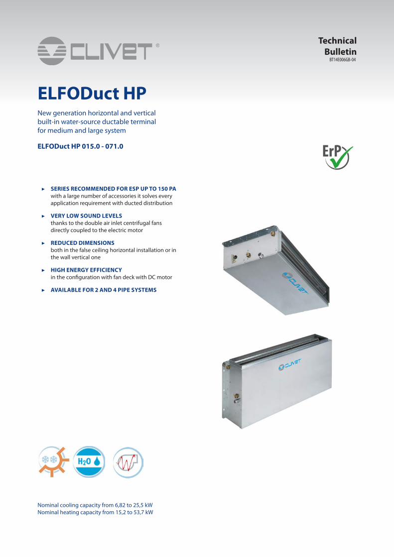
BT14E006GB-04 ELFODuct HP Nominal cooling capacity from 6,82 to 25,5 kW Nominal heating capacity from 15,2 to 53,7 kW ▶ SERIES RECOMMENDED FOR ESP UP TO 150 PA with a large number of accessories it solves every application requirement with ducted distribution ▶ VERY LOW SOUND LEVELS thanks to the double air inlet centrifugal fans directly coupled to the electric motor ▶ REDUCED DIMENSIONS both in the false ceiling horizontal installation or in the wall vertical one ▶ HIGH ENERGY EFFICIENCY in the configuration with fan deck with DC motor ▶ AVAILABLE FOR 2 AND 4 PIPE SYSTEMS Technical Bulletin New generation horizontal and vertical built-in water-source ductable terminal for medium and large system ELFODuct HP 015.0 - 071.0
Transcript of ELFODuct HP - Airview Luchtbehandeling€¦ · 4 ELFODuct HP 015.0 - 071.0 BT14E006GB-04 Standard...
BT14E006GB-04
ELFODuct HP
Nominal cooling capacity from 6,82 to 25,5 kWNominal heating capacity from 15,2 to 53,7 kW
▶ SERIES RECOMMENDED FOR ESP UP TO 150 PAwith a large number of accessories it solves every application requirement with ducted distribution
▶ VERY LOW SOUND LEVELSthanks to the double air inlet centrifugal fans directly coupled to the electric motor
▶ REDUCED DIMENSIONSboth in the false ceiling horizontal installation or in the wall vertical one
▶ HIGH ENERGY EFFICIENCYin the con�guration with fan deck with DC motor
▶ AVAILABLE FOR 2 AND 4 PIPE SYSTEMS
Technical Bulletin
New generation horizontal and vertical built-in water-source ductable terminal for medium and large system
ELFODuct HP 015.0 - 071.0


BT14E006GB-04 ELFODuct HP 015.0 - 071.0 3
Terminal unit ClivetThe hydronic terminal units are very di�used for their versatility and reliability. The Clivet range includes many versions that simplify the application in di�erents type of installation and building.

4 ELFODuct HP 015.0 - 071.0 BT14E006GB-04
Standard unit technical speci�cations
StructureMain casing (= Bearing structure) made of extremely thick steel-sheet, resistant to rust, corrosion, chemical agents, solvents, aliphatics and alcohols. Single skin panel made of galvanized steel + internal thermal-acoustic insulation (class M1) of all parts in contact with the coil.
Self-supporting and removable panels provided with holes (buttonholes) for ceiling/wall mounting directly through the main casing.
Pre-cuts slots and prearranged holes to con�gure the unit on request, to install the accessories, to reverse the unit even on-site.
Assembled with self-threading screws for fast, total and easy check/maintenance.
Reduced sizes, optimised volumes.
Internal exchangerHeat exchanger coil in copper tubes and aluminium �ns, with large surface to increase performances. Each coil is tested under water at 30 bar. Suitable to work with water at max 15 Bar pressure.
Standard connections on the right side (references for position standing in the air�ow with the air blowing on your back) and on request connections on the left side, anyway the unit can be easily reversed even on constuction site.
Coil connections are provided with anti torsion system, manual air vent valves, manual water drain valves.
1 coil (3 or 4 row coils according to the size) for a 2 pipe system and 2 coils (3+2 rows for all sizes) for a 4 pipe system.
FanFan deck including 1, 2 or 3 centrifugal fans with double air inlet aluminium blades (forward curved �ns) directly coupled to the electric motor.
Mounted on elastic and anti vibration supports.
Fan statically and dynamically balanced. Extensive diameter fans with low revolutions.
Electric motor are provided with at least 3 speeds, with heat protection, running capacitor permanently switched on, IP 42, B Class, electric cables protected by double insulation.
Manufactured according to the international standards, 230V–1Ph–50Hz.
Fan deck easy to remove (�xed by just 4 screws).
Drain panDrain pan with double inclination to ensure optimal evacuation of condensation, provided with a discharge (standard on the same side of the water �ttings) + external thermal insulation (M1 class).
Electrical panelIn all series the electrical panel is composed of a simple terminal board for connection to the motor type “Mamut” IP20 (min. 7 poles: 1 Ground + 3 speed + 1 Common + 2 for Bridge) installed outside the unit (for horizontal units, on the same side of the water connections; for vertical units on the opposite side).
Con�guration options
• INV - Vertical uncased version
• SX - Water �ttings to the left
• CC4 - Coil con�guration for 4 pipe system (size 015.0 ÷ 021.0, 031.0 ÷ 061.0)
• R3 - Floor air inlet
• RF - Front air inlet (available only with options: INV)
• VEC - High e�ciency EC fan (available with options: TR, TRM, TRP, TRMP, CTSP1 + CPVM)
• TRM - Terminal block with minimum water temperature clickson
• TRP - Terminal block with closing cover IP40
• TRMP - Terminal block with closing cover IP40 and minimum water temperature clickson
• CTSP1 - CLIVET TALK TERMINAL SPACE electronics with RS485 Modbus serial port
• CPVM - CPVM - Control additional card of 0-10V valve and EC fan (available only with options: CTSP1)

BT14E006GB-04 ELFODuct HP 015.0 - 071.0 5
• RE700 - 0.7 kW integrated electric heater with safety thermostat and power electric panel
• RE1000 - 1.0 kW integrated electric heater with safety thermostat and power electric panel
• RE1500 - 1.5 kW integrated electric heater with safety thermostat and power electric panel
• RE2000 - 2.0 kW integrated electric heater with safety thermostat and power electric panel
• 2V2 - on/o� 2-way valve kit for 2 pipe system (available only with options: CC2)
• 2V4 - on/o� 2-way valve kit for 4 pipe system (available only with options: CC4)
• 3V2 - Three-way valve kit for 2 pipe system type “on/o�” (available only with options: CC2)
• 3V4 - Three-way valve kit for 4 pipe system type “on/o�” (available only with options: CC4)
• 10V2 - 0-10V 3 way valve kit for 2 pipe system (available only with options: CC2)
• 10V4 - 0-10V 3 way valve kit for 4 pipe system (available only with options: CC4)
• CDP - Condensate pump
• BRO - Auxiliary drain pan in galvanized steel with thermal insulation (available only with options: INH)
• BRV - Auxiliary drain pan (vertical installation) (available only with options: INV)
• FAPS - EU3 �at air �lter (Eurovent 4/5) not ductable
• SFCF - Air �lter section (ductable) with EU3 �at air �lter (Eurovent 4/5)
Accessories separately supplied• HIDE2X - Remote control with E/I + 3V + on/o� for wall installation
• HIDE3X - Plurifunctional remote control for wall installation
• HIDE4X - Plurifunctional room control for 0-10V valves
• HIDT2X - HID-T2 electronic room control
• HIDT3X - HID-T3 electronic room control
• HIDTI8X - HID-TI8X electronic room control for 3-speed or 0-10V fan and on/o� or 0-10V valve
• DCPX - Control device for more units with a single room control
• PTABX - Remote probe for room air temperature for electromechanical thermostats
• TMX - Hot water min. temperature thermostat
• EH2QX - Heating section with 230V electric heaters, safety thermostat and power electric panel
• EH4QX - Heating section with 400V electric heaters, safety thermostat and power electric panel
• KIB22X - Water and balancing kit for 2-way valve and 2-pipe installation (available only with options: CC2)
• KIB24X - Water and balancing kit for 2-way valve and 4-pipe installation (available only with options: CC4)
• KIB32X - Water and balancing kit for 3-way valve and 2-pipe installation (available only with options: CC2)
• KIB34X - Water and balancing kit for 3-way valve and 4-pipe installation (available only with options: CC4)
• SFHEX - Air �lter section (ductable) with EU5 air �lter (Eurovent 4/5)
• CUFMX - Air outlet casing with bird-proof grill
• CUFAX - Air intake casing with bird-proof grill and EU3 air �lter (Eurovent 4/5)
• PCCMAX - Section with spigots “Ø” with variable diameter and internal insulation for both air supply outlets
• PCCRIX - Section with spigots “Ø” with variable diameter and internal insulation for air intake outlets.
• P90MAX - 90° section for both air supply outlets
• PR90AX - 90° air intake plenum
• SILMAX - Labyrinth noise level attenuator section for both air intake / supply outlets
• MCRX - Mixing and recirculating chamber
• S230X - ON/OFF 230V servomotor for mixing and recirculation chamber (available only with options: MCRX)
• GMX - Supply grille
• GRAX - Return grille with �lter
• PMAX - Straight section for both air intake / supply outlets
• PGFMAX - Anti-vibration section for both air supply outlets
• PGFRIX - Anti-vibration section for air intake outlets.

6 ELFODuct HP 015.0 - 071.0 BT14E006GB-04
Con�guration Code
(1) Voltage• Supply voltage 230/1/50
(2) Versions• INH - Uncased horizontal version (standard)• INV - Vertical uncased version
(3) Water �ttings• DX - Water connection to the right (standard)• SX - Water connections to the left
(4) Coil con�guration• CC2 - Coil con�guration for 2 pipe system (standard)• CC4 - Coil con�guration for 4 pipe system (sizes 015.0 ÷ 021.0, 031.0 ÷ 061.0)
(5) Air inlet• RP - Rear intake (standard)• R3 - Floor air inlet• RF - Front air inlet (available only with options: INV)
(6) Fans• VENS - AC fans (standard)• VEC - High e�ciency EC fan (available with options: TR, TRM, TRP, TRMP, CTSP1 + CPVM)
(7) Electrical panel• TR - Terminal boards for connection motor (standard)• TRM - Terminal block with minimum water temperature clickson• TRP - Terminal block with closing cover IP40• TRMP - Terminal block with closing cover IP40 and minimum water temperature clickson
(8) Electronic version• (-) Not required (standard)• CTSP1 - CLIVET TALK TERMINAL SPACE electronics with RS485 Modbus serial port
(9) Additional cards• (-) Not required (standard)• CPVM - Control additional card of 0-10V valve and EC fan (available only with options: CTSP1)
(10) Electric heaters• (-) Not required (standard)• RE700 - 0.7 kW integrated electric heater with safety thermostat and power electric panel• RE1000 - 1.0 kW integrated electric heater with safety thermostat and power electric panel• RE1500 - 1.5 kW integrated electric heater with safety thermostat and power electric panel• RE2000 - 2.0 kW integrated electric heater with safety thermostat and power electric panel
(11) 2-way valves• (-) Not required (standard)• 2V2 - on/o� 2-way valve kit for 2 pipe system (available only with options: CC2)• 2V4 - on/o� 2-way valve kit for 4 pipe system (available only with options: CC4)
(12) 3-way valves• (-) Not required (standard)• 3V2 - Three-way valve kit for 2 pipe system type “on/o�” (available only with options: CC2)• 3V4 - Three-way valve kit for 4 pipe system type “on/o�” (available only with options: CC4)• 10V2 - 0-10V 3 way valve kit for 2 pipe system (available only with options: CC2)• 10V4 - 0-10V 3 way valve kit for 4 pipe system (available only with options: CC4)
(13) Condensate pump• (-) Not required (standard)• CDP - Condensate pump
(14) Auxiliary condensate collection tray• (-) Not required (standard)• BRO - Auxiliary drain pan in galvanized steel with thermal insulation (available only with options: INH)• BRV - Auxiliary drain pan (vertical installation) (available only with options: INV)
(15)Air �lter• (-) Not required (standard)• FAPS - EU3 �at air �lter (Eurovent 4/5) not ductable• SFCF - Air �lter section (ductable) with EU3 �at air �lter (Eurovent 4/5)

BT14E006GB-04 ELFODuct HP 015.0 - 071.0 7
Ductable uncased horizontal version (INH)
RP - Rear intake (standard) R3 - Floor air inlet
DX - Water connection to the right (standard) DX - Water connection to the right (standard)
Ductable uncased vertical version (INV)
R3 - Floor air inlet RF - Front air intake
DX - Water connection to the right (standard) DX - Water connection to the right (standard)
References for position of �ttings: right and left de�ned by standing in the air�ow (with the air blowing on your back).

8 ELFODuct HP 015.0 - 071.0 BT14E006GB-04
General technical data - 2 pipe system (CC2) AC fans (standard)
Size 015.0 021.0 025.0 031.0 041.0 051.0 061.0 071.0
Cooling
Cooling capacity (1) [kW] 6,82 8,65 10,1 12,0 15,2 17,8 21,2 25,5
Sensible capacity (1) [kW] 5,3 6,58 7,38 9,78 12,1 13,5 17,2 19,4
Total power input (1) [kW] 0,29 0,29 0,29 0,56 0,56 0,56 0,65 0,65
Heating
Heating capacity (2) [kW] 15,2 18,9 20,0 28,4 35,2 37,2 50,3 53,7
Internal exchanger
Number of rows [Nr] 3 3 4 3 3 4 3 4
Water volume [l] 1,9 2 2,7 2,9 3 4 4 5,3
Water �ow-rate (1) [l/s] 0,33 0,41 0,48 0,57 0,73 0,85 1,01 1,22
Water pressure drops (1) [kPa] 35,7 39,4 38,4 28 38,3 30,6 29,7 25,0
Water pressure drops (2) [kPa] 34,6 36,6 29,4 31 40,0 26,1 32,6 21,6
Air Handling Section Fans (Supply)
Type of fans (3) CFG CFG CFG CFG CFG CFG CFG CFG
Number of fans [Nr] 1 1 1 2 2 2 3 3
Air�ow (4) [l/s] 375 417 403 764 833 792 1222 1167
Air�ow (4) [m3/h] 1350 1500 1450 2750 3000 2850 4400 4200
Max external static pressure [Pa] 184 194 194 182 192 192 196 196
Connections
Water �ttings “ 3/4”F 3/4”F 3/4”F 3/4”F 3/4”F 3/4”F 3/4”F 3/4”F
Condensate drain (5) [mm] 20 20 20 20 20 20 20 20
Noise levels
Sound press. level (1m) (6) [dB(A)] 58 59 59 61 62 62 63 63
Sound Power Level (6) [dB(A)] 69 70 70 72 73 73 74 74
Power supply STD
Power supply STD [V] 230/1/50 230/1/50 230/1/50 230/1/50 230/1/50 230/1/50 230/1/50 230/1/50
The Product is compliant with the Erp (Energy Related Products) European Directive. It includes the Commission delegated Regulation (EU) No 2016/2281, also known as Ecodesign Lot21.‘Contains �uorinated greenhouse gases’(GWP 2087,5) (1) Indoor air at 27°C D.B/19° C W.B.Water temperature in / out 7°C / 12°CAir �ow at maximum speed (ESP = 0Pa)(2) Indoor air temperature at 20°CWater inlet 70°C and outlet 60°CAir �ow at maximum speed (ESP = 0Pa)
(3) CFG = AC centrifugal fan(4) Air �ow at maximum speed - (ESP = 0Pa)(5) Intended as an external diameter(6) The sound levels refer to ceiling units without false ceiling, with nominal air �ow, fan supply 220V, at maximum speed. Sound pressure levels referred to 1 m from unit external surface. Measurement maded with intake plenum and air �lter mounted.
Electrical data - 2 pipe system (CC2)AC fans (standard) Voltage 230/1/50 ± 10%
Size 015.0 021.0 025.0 031.0 041.0 051.0 061.0 071.0
F.L.A. - Full load current at max admissible conditions
FLA Total [A] 1,3 1,3 1,3 2,6 2,6 2,6 3 3
F.L.I. - Full load power input at max admissible conditions
FLI Total [kW] 0,29 0,29 0,29 0,56 0,56 0,56 0,65 0,65
(1) Indoor air at 27°C D.B/19° C W.B.Water temperature in / out 7°C / 12°CAir �ow at maximum speed (ESP = 0Pa)
(2) Indoor air temperature at 20°CWater inlet 70°C and outlet 60°CAir �ow at maximum speed (ESP = 0Pa)

BT14E006GB-04 ELFODuct HP 015.0 - 071.0 9
General technical data - 4 pipe system (CC4) AC fans (standard)
Size 015.0 021.0 031.0 041.0 051.0 061.0
Cooling
Cooling capacity (1) [kW] 6,57 8,28 11,5 14,6 16,1 20,3
Sensible capacity (1) [kW] 5,07 6,25 9,33 11,5 13,3 16,4
Total power input (1) [kW] 0,29 0,29 0,56 0,56 0,65 0,65
Heating
Heating capacity (2) [kW] 12,1 12,9 22,3 23,6 31,9 33,6
Internal exchanger
Number of rows [Nr] 3 + 2 3 + 2 3 + 2 3 + 2 3 + 2 3 + 2
Water volume [l] 1,9 + 1,1 2 + 1,1 2,9 + 1,7 3 + 1,7 4 + 2,3 4 + 2,3
Water �ow-rate (1) [l/s] 0,31 0,4 0,55 0,7 0,77 0,97
Water pressure drops (1) [kPa] 33,1 36,1 25,7 35,3 19,5 27,2
Water pressure drops (2) [kPa] 35,5 39,2 32,3 35,6 29,7 32,4
Air Handling Section Fans (Supply)
Type of fans (3) CFG CFG CFG CFG CFG CFG
Number of fans [Nr] 1 1 2 2 3 3
Air�ow (4) [l/s] 353 389 714 778 1056 1139
Air�ow (4) [m3/h] 1270 1400 2570 2800 3800 4100
Max external static pressure [Pa] 186 196 184 192 186 196
Connections
Water �ttings “ 3/4”F+ 1/2”F 3/4”F+ 1/2”F 3/4”F+ 1/2”F 3/4”F+ 1/2”F 3/4”F+ 1/2”F 3/4”F+ 1/2”F
Condensate drain (5) [mm] 20 20 20 20 20 20
Noise levels
Sound pressure level (1m) (6) [dB(A)] 58 59 61 62 62 63
Sound Power Level (6) [dB(A)] 69 70 72 73 73 74
Power supply STD
Power supply STD [V] 230/1/50 230/1/50 230/1/50 230/1/50 230/1/50 230/1/50
The Product is compliant with the Erp (Energy Related Products) European Directive. It includes the Commission delegated Regulation (EU) No 2016/2281, also known as Ecodesign Lot21.‘Contains �uorinated greenhouse gases’(GWP 2087,5)
(1) Indoor air at 27°C D.B/19° C W.B.Water temperature in / out 7°C / 12°CAir �ow at maximum speed (ESP = 0Pa)(2) Indoor air temperature at 20°CWater inlet 70°C and outlet 60°CAir �ow at maximum speed (ESP = 0Pa)
(3)CFG = AC centrifugal fan(4) Air �ow at maximum speed - (ESP = 0Pa)(5) Intended as an external diameter(6) The sound levels refer to ceiling units without false ceiling, with nominal air �ow, fan supply 220V, at maximum speed. Sound pressure levels referred to 1 m from unit external surface. Measurement maded with intake plenum and air �lter mounted.
Electrical data - 4 pipe system (CC4)
AC fans (standard) Voltage 230/1/50 ± 10%
Size 015.0 021.0 031.0 041.0 051.0 061.0
F.L.A. - Full load current at max admissible conditions
FLA Total [A] 1,3 1,3 2,6 2,6 3 3
F.L.I. - Full load power input at max admissible conditions
FLI Total [kW] 0,29 0,29 0,56 0,56 0,65 0,65
(1) Indoor air at 27°C D.B/19° C W.B.Water temperature in / out 7°C / 12°CAir �ow at maximum speed (ESP = 0Pa)
(2) Indoor air temperature at 20°CWater inlet 70°C and outlet 60°CAir �ow at maximum speed (ESP = 0Pa)

10 ELFODuct HP 015.0 - 071.0 BT14E006GB-04
Operating limits
2 pipe system (CC2)
Size 015.0 021.0 025.0 031.0 041.0 051.0 061.0 071.0
Heating
Max inlet water temperature [°C] 100 100 100 100 100 100 100 100
Min inlet water temperature [°C] 3 3 3 3 3 3 3 3
Max D.B. air inlet temperature [°C] 40 40 40 40 40 40 40 40
Min D.B. air inlet temperature [°C] 2 2 2 2 2 2 2 2
Cooling
Max W.B. air inlet temperature [°C] 40 40 40 40 40 40 40 40
Min W.B. air inlet temperature [°C] 2 2 2 2 2 2 2 2
Maximum water side pressure [bar] 30 30 30 30 30 30 30 30
Max water side pressure = Coil max pressure. In presence of accessories (for example 2-3 way valves) the max water side pressure is 15 bar.
4-pipe system (CC4)
Size 015.0 021.0 031.0 041.0 051.0 061.0
Heating
Max inlet water temperaturet [°C] 100 100 100 100 100 100
Min inlet water temperature [°C] 3 3 3 3 3 3
Max D.B. air inlet temperature [°C] 40 40 40 40 40 40
Min D.B. air inlet temperature [°C] 2 2 2 2 2 2
Cooling
Max W.B. air inlet temperature [°C] 40 40 40 40 40 40
Min W.B. air inlet temperature [°C] 2 2 2 2 2 2
Maximum water side pressure [bar] 30 30 30 30 30 30
Max water side pressure = Coil max pressure. In presence of accessories (for example 2-3 way valves) the max water side pressure is 15 bar.
Sound levels
Lw Total sound power emitted by the unit Lwi Radiated sound power, emitted by the lateral surfaces of the unit Lwm Sound power emitted by the air supply side of the unit Lwa Sound power emitted by the air intake side of the unit

BT14E006GB-04 ELFODuct HP 015.0 - 071.0 11
Sound power level (dB) Sound pressure
level
Sound power levelOctave band (Hz)
Static pressure
Sound power
Fan speed 125 250 500 1000 2000 4000 8000 dB(A) dB(A)
0 Pa
Lw
Min 53,1 55,2 51,9 50,2 46,8 40,9 32,2 44 55
Med 60,7 62,9 59,2 58,7 54,7 51,7 44,6 52 63
Max 64,6 68,8 64,1 65,0 60,8 58,3 53,0 58 69
Lwi
Min 35,3 34,7 26,4 21,9 12,4 n.m. n.m. 18 29
Med 42,9 42,4 33,6 30,5 20,2 11,7 n.m. 26 37
Max 46,8 48,3 38,5 36,7 26,4 18,3 7,7 32 43
Lwm
Min 49,5 51,3 45,4 45,1 43,8 37,4 28,6 39 50
Med 57,0 59,0 52,6 53,7 51,6 48,2 41,0 48 59
Max 60,9 64,9 57,6 60,0 57,8 54,8 49,4 54 65
Lwa
Min 50,5 52,8 50,8 48,5 43,8 38,3 29,6 42 53
Med 58,1 60,6 58,1 57,1 51,7 49,1 42,1 50 61
Max 62,0 66,4 63,0 63,4 57,8 55,7 50,4 56 67
50 Pa
Lw
Min 54,8 56,8 53,6 51,8 48,5 42,5 33,8 46 57
Med 62,3 64,6 60,8 60,4 56,3 53,4 46,3 54 65
Max 66,2 70,4 65,7 66,7 62,5 59,9 54,6 60 71
Lwi
Min 36,9 36,3 28,0 23,6 14,0 n.m. n.m. 20 31
Med 44,5 44,1 35,3 32,1 21,9 13,4 n.m. 28 39
Max 48,4 49,9 40,2 38,4 28,1 20,0 9,3 33 44
Lwm
Min 51,1 52,9 47,0 46,8 45,4 39,0 30,3 41 52
Med 58,7 60,7 54,3 55,4 53,3 49,9 42,7 49 60
Max 62,6 66,5 59,2 61,6 59,5 56,4 51,0 55 66
Lwa
Min 52,2 54,5 52,4 50,2 45,5 40,0 31,3 44 55
Med 59,7 62,3 59,7 58,8 53,3 50,8 43,8 52 63
Max 63,6 68,1 64,6 65,0 59,5 57,3 52,1 58 69
100 Pa
Lw
Min 56,4 58,5 55,2 53,5 50,1 44,2 35,5 47 58
Med 64,0 66,3 62,5 62,1 58,0 55,0 47,9 55 66
Max 67,9 72,1 67,4 68,3 64,2 61,6 56,3 61 72
Lwi
Min 38,6 38,0 29,7 25,2 15,7 n.m. n.m. 22 33
Med 46,2 45,7 37,0 33,8 23,5 15,1 n.m. 30 41
Max 50,1 51,6 41,9 40,1 29,7 21,6 11,0 35 46
Lwm
Min 52,8 54,6 48,7 48,4 47,1 40,7 31,9 43 54
Med 60,4 62,4 56,0 57,0 55,0 51,5 44,4 51 62
Max 64,3 68,2 60,9 63,3 61,1 58,1 52,7 57 68
Lwa
Min 53,8 56,2 54,1 51,9 47,1 41,6 33,0 45 56
Med 61,4 63,9 61,4 60,4 55,0 52,4 45,4 53 64
Max 65,3 69,8 66,3 66,7 61,2 59,0 53,8 59 70
150 Pa
Lw
Min 58,1 60,2 56,9 55,2 51,8 45,9 37,1 49 60
Med 65,6 67,9 64,1 63,7 59,6 56,7 49,6 57 68
Max 69,6 73,8 69,1 70,0 65,8 63,2 57,9 63 74
Lwi
Min 40,3 39,6 31,4 26,9 17,4 5,9 n.m. 23 34
Med 47,8 47,4 38,6 35,5 25,2 16,7 n.m. 31 42
Max 51,7 53,2 43,5 41,7 31,4 23,3 12,6 37 48
Lwm
Min 54,4 56,3 50,4 50,1 48,8 42,4 33,6 44 55
Med 62,0 64,0 57,6 58,7 56,6 53,2 46,0 53 64
Max 65,9 69,9 62,5 64,9 62,8 59,7 54,4 59 70
Lwa
Min 55,5 57,8 55,8 53,5 48,8 43,3 34,6 47 58
Med 63,1 65,6 63,0 62,1 56,6 54,1 47,1 55 66
Max 67,0 71,4 67,9 68,4 62,8 60,7 55,4 61 72The sound levels refer to ceiling units without false ceiling, fan supply 220V.Sound pressure levels referred to 1 m from unit external surface.Measurement maded with intake plenum and air �lter mounted.n.m. = not measurable
Sound levels - Size 015.0 (CC2-CC4)

12 ELFODuct HP 015.0 - 071.0 BT14E006GB-04
Sound levels - Size 021.0 (CC2-CC4) and 025.0 (CC2)
Sound power level (dB) Sound pressure
level
Sound power levelOctave band (Hz)
Static pressure
Sound power
Fan speed 125 250 500 1000 2000 4000 8000 dB(A) dB(A)
0 Pa
Lw
Min 54,1 56,2 52,9 51,2 47,8 41,9 33,2 45 56
Med 61,7 63,9 60,2 59,7 55,7 52,7 45,6 53 64
Max 65,6 69,8 65,1 66,0 61,8 59,3 54,0 59 70
Lwi
Min 36,3 35,7 27,4 22,9 13,4 n.m. n.m. 19 30
Med 43,9 43,4 34,6 31,5 21,2 12,7 n.m. 27 38
Max 47,8 49,3 39,5 37,7 27,4 19,3 8,7 33 44
Lwm
Min 50,5 52,3 46,4 46,1 44,8 38,4 29,6 40 51
Med 58,0 60,0 53,6 54,7 52,6 49,2 42,0 49 60
Max 61,9 65,9 58,6 61,0 58,8 55,8 50,4 55 66
Lwa
Min 51,5 53,8 51,8 49,5 44,8 39,3 30,6 43 54
Med 59,1 61,6 59,1 58,1 52,7 50,1 43,1 51 62
Max 63,0 67,4 64,0 64,4 58,8 56,7 51,4 57 68
50 Pa
Lw
Min 55,8 57,8 54,6 52,8 49,5 43,5 34,8 47 58
Med 63,3 65,6 61,8 61,4 57,3 54,4 47,3 55 66
Max 67,2 71,4 66,7 67,7 63,5 60,9 55,6 61 72
Lwi
Min 37,9 37,3 29,0 24,6 15,0 n.m. n.m. 21 32
Med 45,5 45,1 36,3 33,1 22,9 14,4 n.m. 29 40
Max 49,4 50,9 41,2 39,4 29,1 21,0 10,3 34 45
Lwm
Min 52,1 53,9 48,0 47,8 46,4 40,0 31,3 42 53
Med 59,7 61,7 55,3 56,4 54,3 50,9 43,7 50 61
Max 63,6 67,5 60,2 62,6 60,5 57,4 52,0 56 67
Lwa
Min 53,2 55,5 53,4 51,2 46,5 41,0 32,3 45 56
Med 60,7 63,3 60,7 59,8 54,3 51,8 44,8 53 64
Max 64,6 69,1 65,6 66,0 60,5 58,3 53,1 59 70
100 Pa
Lw
Min 57,4 59,5 56,2 54,5 51,1 45,2 36,5 48 59
Med 65,0 67,3 63,5 63,1 59,0 56,0 48,9 56 67
Max 68,9 73,1 68,4 69,3 65,2 62,6 57,3 62 73
Lwi
Min 39,6 39,0 30,7 26,2 16,7 5,2 n.m. 23 34
Med 47,2 46,7 38,0 34,8 24,5 16,1 n.m. 31 42
Max 51,1 52,6 42,9 41,1 30,7 22,6 12,0 36 47
Lwm
Min 53,8 55,6 49,7 49,4 48,1 41,7 32,9 44 55
Med 61,4 63,4 57,0 58,0 56,0 52,5 45,4 52 63
Max 65,3 69,2 61,9 64,3 62,1 59,1 53,7 58 69
Lwa
Min 54,8 57,2 55,1 52,9 48,1 42,6 34,0 46 57
Med 62,4 64,9 62,4 61,4 56,0 53,4 46,4 54 65
Max 66,3 70,8 67,3 67,7 62,2 60,0 54,8 60 71
150 Pa
Lw
Min 59,1 61,2 57,9 56,2 52,8 46,9 38,1 50 61
Med 66,6 68,9 65,1 64,7 60,6 57,7 50,6 58 69
Max 70,6 74,8 70,1 71,0 66,8 64,2 58,9 64 75
Lwi
Min 41,3 40,6 32,4 27,9 18,4 6,9 n.m. 24 35
Med 48,8 48,4 39,6 36,5 26,2 17,7 5,3 32 43
Max 52,7 54,2 44,5 42,7 32,4 24,3 13,6 38 49
Lwm
Min 55,4 57,3 51,4 51,1 49,8 43,4 34,6 45 56
Med 63,0 65,0 58,6 59,7 57,6 54,2 47,0 54 65
Max 66,9 70,9 63,5 65,9 63,8 60,7 55,4 60 71
Lwa
Min 56,5 58,8 56,8 54,5 49,8 44,3 35,6 48 59
Med 64,1 66,6 64,0 63,1 57,6 55,1 48,1 56 67
Max 68,0 72,4 68,9 69,4 63,8 61,7 56,4 62 73
The sound levels refer to ceiling units without false ceiling, fan supply 220V.Sound pressure levels referred to 1 m from unit external surface.Measurement maded with intake plenum and air �lter mounted.n.m. = not measurable

BT14E006GB-04 ELFODuct HP 015.0 - 071.0 13
Sound levels - Size 031.0 (CC2-CC4)
Sound power level (dB) Sound pressure
level
Sound power levelOctave band (Hz)
Static pressure
Sound power
Fan speed 125 250 500 1000 2000 4000 8000 dB(A) dB(A)
0 Pa
Lw
Min 53,6 57,6 54,6 51,4 49,7 43,4 35,3 46 57
Med 63,3 67,3 64,8 63,4 59,7 57,5 51,3 57 68
Max 66,0 70,4 68,1 67,7 63,1 60,9 55,8 61 72
Lwi
Min 35,7 37,1 29,1 23,1 15,2 n.m. n.m. 21 32
Med 45,5 46,7 39,2 35,1 25,3 17,6 6,0 31 42
Max 48,2 49,9 42,5 39,4 28,7 20,9 10,5 34 45
Lwm
Min 49,8 53,6 48,0 46,2 46,5 39,8 31,7 41 52
Med 59,6 63,2 58,1 58,2 56,6 53,9 47,7 52 63
Max 62,2 66,4 61,4 62,5 60,0 57,3 52,1 56 67
Lwa
Min 51,1 55,4 53,6 49,8 46,8 40,9 32,9 44 55
Med 60,8 65,0 63,7 61,8 56,9 55,0 48,9 55 66
Max 63,5 68,2 67,0 66,2 60,3 58,4 53,3 59 70
50 Pa
Lw
Min 55,3 59,4 56,4 53,2 51,5 45,2 37,1 48 59
Med 65,1 69,0 66,6 65,2 61,5 59,3 53,1 59 70
Max 67,8 72,2 69,9 69,5 64,9 62,7 57,6 63 74
Lwi
Min 37,5 38,9 30,9 24,9 17,0 5,2 n.m. 22 33
Med 47,3 48,5 41,0 36,9 27,1 19,3 7,8 33 44
Max 50,0 51,7 44,3 41,2 30,5 22,7 12,3 36 47
Lwm
Min 51,6 55,4 49,8 47,9 48,3 41,6 33,5 43 54
Med 61,4 65,0 59,9 60,0 58,4 55,7 49,5 54 65
Max 64,0 68,2 63,2 64,3 61,7 59,1 53,9 58 69
Lwa
Min 52,9 57,1 55,4 51,6 48,6 42,7 34,7 46 57
Med 62,6 66,8 65,5 63,6 58,7 56,8 50,7 57 68
Max 65,3 70,0 68,8 67,9 62,1 60,2 55,1 61 72
100 Pa
Lw
Min 57,1 61,2 58,2 54,9 53,2 47,0 38,9 50 61
Med 66,9 70,8 68,3 67,0 63,3 61,1 54,9 61 72
Max 69,6 74,0 71,6 71,3 66,7 64,5 59,3 64 75
Lwi
Min 39,3 40,7 32,7 26,7 18,8 7,0 n.m. 24 35
Med 49,1 50,3 42,8 38,7 28,9 21,1 9,6 34 45
Max 51,8 53,5 46,1 43,0 32,3 24,5 14,0 38 49
Lwm
Min 53,4 57,1 51,6 49,7 50,1 43,4 35,2 45 56
Med 63,1 66,8 61,7 61,7 60,1 57,5 51,2 56 67
Max 65,8 70,0 65,0 66,1 63,5 60,9 55,7 60 71
Lwa
Min 54,6 58,9 57,1 53,4 50,4 44,5 36,5 48 59
Med 64,4 68,6 67,3 65,4 60,5 58,6 52,5 59 70
Max 67,1 71,8 70,6 69,7 63,9 62,0 56,9 63 74
150 Pa
Lw
Min 58,9 63,0 60,0 56,7 55,0 48,8 40,7 51 62
Med 68,7 72,6 70,1 68,8 65,1 62,9 56,7 62 73
Max 71,4 75,8 73,4 73,1 68,5 66,3 61,1 66 77
Lwi
Min 41,1 42,4 34,5 28,5 20,6 8,8 n.m. 26 37
Med 50,9 52,1 44,6 40,5 30,7 22,9 11,4 36 47
Max 53,6 55,3 47,9 44,8 34,1 26,3 15,8 40 51
Lwm
Min 55,2 58,9 53,4 51,5 51,8 45,2 37,0 47 58
Med 64,9 68,6 63,5 63,5 61,9 59,3 53,0 58 69
Max 67,6 71,8 66,8 67,9 65,3 62,6 57,5 62 73
Lwa
Min 56,4 60,7 58,9 55,2 52,2 46,3 38,3 50 61
Med 66,2 70,4 69,1 67,2 62,3 60,4 54,2 61 72
Max 68,9 73,5 72,3 71,5 65,7 63,8 58,7 64 75
The sound levels refer to ceiling units without false ceiling, fan supply 220V.Sound pressure levels referred to 1 m from unit external surface.Measurement maded with intake plenum and air �lter mounted.n.m. = not measurable

14 ELFODuct HP 015.0 - 071.0 BT14E006GB-04
Sound levels - Size 041.0 (CC2-CC4) and 051.0 (CC2)
Sound power level (dB) Sound pressure
level
Sound power levelOctave band (Hz)
Static pressure
Sound power
Fan speed 125 250 500 1000 2000 4000 8000 dB(A) dB(A)
0 Pa
Lw
Min 54,6 58,6 55,6 52,4 50,7 44,4 36,3 47 58
Med 64,3 68,3 65,8 64,4 60,7 58,5 52,3 58 69
Max 67,0 71,4 69,1 68,7 64,1 61,9 56,8 62 73
Lwi
Min 36,7 38,1 30,1 24,1 16,2 n.m. n.m. 22 33
Med 46,5 47,7 40,2 36,1 26,3 18,6 7,0 32 43
Max 49,2 50,9 43,5 40,4 29,7 21,9 11,5 35 46
Lwm
Min 50,8 54,6 49,0 47,2 47,5 40,8 32,7 42 53
Med 60,6 64,2 59,1 59,2 57,6 54,9 48,7 53 64
Max 63,2 67,4 62,4 63,5 61,0 58,3 53,1 57 68
Lwa
Min 52,1 56,4 54,6 50,8 47,8 41,9 33,9 45 56
Med 61,8 66,0 64,7 62,8 57,9 56,0 49,9 56 67
Max 64,5 69,2 68,0 67,2 61,3 59,4 54,3 60 71
50 Pa
Lw
Min 56,3 60,4 57,4 54,2 52,5 46,2 38,1 49 60
Med 66,1 70,0 67,6 66,2 62,5 60,3 54,1 60 71
Max 68,8 73,2 70,9 70,5 65,9 63,7 58,6 64 75
Lwi
Min 38,5 39,9 31,9 25,9 18,0 6,2 n.m. 23 34
Med 48,3 49,5 42,0 37,9 28,1 20,3 8,8 34 45
Max 51,0 52,7 45,3 42,2 31,5 23,7 13,3 37 48
Lwm
Min 52,6 56,4 50,8 48,9 49,3 42,6 34,5 44 55
Med 62,4 66,0 60,9 61,0 59,4 56,7 50,5 55 66
Max 65,0 69,2 64,2 65,3 62,7 60,1 54,9 59 70
Lwa
Min 53,9 58,1 56,4 52,6 49,6 43,7 35,7 47 58
Med 63,6 67,8 66,5 64,6 59,7 57,8 51,7 58 69
Max 66,3 71,0 69,8 68,9 63,1 61,2 56,1 62 73
100 Pa
Lw
Min 58,1 62,2 59,2 55,9 54,2 48,0 39,9 51 62
Med 67,9 71,8 69,3 68,0 64,3 62,1 55,9 62 73
Max 70,6 75,0 72,6 72,3 67,7 65,5 60,3 65 76
Lwi
Min 40,3 41,7 33,7 27,7 19,8 8,0 n.m. 25 36
Med 50,1 51,3 43,8 39,7 29,9 22,1 10,6 35 46
Max 52,8 54,5 47,1 44,0 33,3 25,5 15,0 39 50
Lwm
Min 54,4 58,1 52,6 50,7 51,1 44,4 36,2 46 57
Med 64,1 67,8 62,7 62,7 61,1 58,5 52,2 57 68
Max 66,8 71,0 66,0 67,1 64,5 61,9 56,7 61 72
Lwa
Min 55,6 59,9 58,1 54,4 51,4 45,5 37,5 49 60
Med 65,4 69,6 68,3 66,4 61,5 59,6 53,5 60 71
Max 68,1 72,8 71,6 70,7 64,9 63,0 57,9 64 75
150 Pa
Lw
Min 59,9 64,0 61,0 57,7 56,0 49,8 41,7 52 63
Med 69,7 73,6 71,1 69,8 66,1 63,9 57,7 63 74
Max 72,4 76,8 74,4 74,1 69,5 67,3 62,1 67 78
Lwi
Min 42,1 43,4 35,5 29,5 21,6 9,8 n.m. 27 38
Med 51,9 53,1 45,6 41,5 31,7 23,9 12,4 37 48
Max 54,6 56,3 48,9 45,8 35,1 27,3 16,8 41 52
Lwm
Min 56,2 59,9 54,4 52,5 52,8 46,2 38,0 48 59
Med 65,9 69,6 64,5 64,5 62,9 60,3 54,0 59 70
Max 68,6 72,8 67,8 68,9 66,3 63,6 58,5 63 74
Lwa
Min 57,4 61,7 59,9 56,2 53,2 47,3 39,3 51 62
Med 67,2 71,4 70,1 68,2 63,3 61,4 55,2 62 73
Max 69,9 74,5 73,3 72,5 66,7 64,8 59,7 65 76
The sound levels refer to ceiling units without false ceiling, fan supply 220V.Sound pressure levels referred to 1 m from unit external surface.Measurement maded with intake plenum and air �lter mounted.n.m = not measurable

BT14E006GB-04 ELFODuct HP 015.0 - 071.0 15
Sound levels - Size 051.0 (CC4)
Sound power level (dB) Sound pressure
level
Sound power levelOctave band (Hz)
Static pressure
Sound power
Fan speed 125 250 500 1000 2000 4000 8000 dB(A) dB(A)
0 Pa
Lw
Min 61,5 65,5 65,8 61,0 57,3 53,4 46,9 56 67
Med 67,1 70,1 68,4 67,2 63,1 59,4 54,3 61 72
Max 70,0 72,7 70,2 69,1 65,1 61,0 56,7 62 73
Lwi
Min 43,7 45,0 40,3 32,7 22,9 13,5 n.m. 30 41
Med 49,3 49,6 42,9 38,9 28,7 19,4 9,0 34 45
Max 52,2 52,2 44,7 40,8 30,6 21,0 11,4 36 47
Lwm
Min 57,6 61,4 59,0 55,6 54,0 49,7 43,2 51 62
Med 63,2 65,9 61,7 61,8 59,8 55,6 50,5 56 67
Max 66,1 68,5 63,4 63,7 61,7 57,3 52,9 58 69
Lwa
Min 59,1 63,4 64,8 59,5 54,6 51,1 44,6 54 65
Med 64,7 68,0 67,4 65,7 60,5 57,0 51,9 59 70
Max 67,6 70,5 69,1 67,6 62,4 58,6 54,3 61 72
50 Pa
Lw
Min 63,4 67,5 67,7 62,9 59,3 55,4 48,8 58 69
Med 69,0 72,0 70,4 69,1 65,1 61,3 56,2 62 73
Max 71,9 74,6 72,1 71,0 67,0 62,9 58,6 64 75
Lwi
Min 45,6 46,9 42,2 34,7 24,8 15,4 n.m. 32 43
Med 51,2 51,5 44,8 40,8 30,6 21,3 10,9 36 47
Max 54,1 54,1 46,6 42,7 32,5 23,0 13,3 38 49
Lwm
Min 59,5 63,3 61,0 57,5 55,9 51,6 45,1 52 63
Med 65,1 67,8 63,6 63,7 61,7 57,6 52,4 58 69
Max 68,0 70,4 65,3 65,6 63,6 59,2 54,8 60 71
Lwa
Min 61,1 65,3 66,7 61,4 56,6 53,0 46,5 56 67
Med 66,6 69,9 69,3 67,6 62,4 58,9 53,8 61 72
Max 69,5 72,5 71,0 69,5 64,3 60,5 56,2 63 74
100 Pa
Lw
Min 65,4 69,4 69,6 64,8 61,2 57,3 50,8 59 70
Med 70,9 73,9 72,3 71,0 67,0 63,2 58,1 64 75
Max 73,9 76,5 74,0 72,9 68,9 64,8 60,5 66 77
Lwi
Min 47,5 48,9 44,1 36,6 26,7 17,3 5,5 34 45
Med 53,1 53,4 46,7 42,8 32,5 23,3 12,8 38 49
Max 56,0 56,0 48,5 44,6 34,4 24,9 15,2 40 51
Lwm
Min 61,5 65,2 62,9 59,4 57,8 53,5 47,0 54 65
Med 67,0 69,8 65,5 65,6 63,6 59,5 54,4 59 70
Max 69,9 72,3 67,3 67,5 65,5 61,1 56,7 61 72
Lwa
Min 63,0 67,2 68,6 63,4 58,5 54,9 48,4 58 69
Med 68,5 71,8 71,2 69,5 64,3 60,8 55,7 63 74
Max 71,5 74,4 73,0 71,4 66,2 62,4 58,1 65 76
150 Pa
Lw
Min 67,3 71,3 71,5 66,8 63,1 59,2 52,7 61 72
Med 72,8 75,8 74,2 72,9 68,9 65,1 60,0 66 77
Max 75,8 78,4 75,9 74,8 70,8 66,7 62,4 68 79
Lwi
Min 49,5 50,8 46,0 38,5 28,6 19,2 7,4 36 47
Med 55,0 55,3 48,7 44,7 34,5 25,2 14,7 40 51
Max 57,9 57,9 50,4 46,5 36,4 26,8 17,1 42 53
Lwm
Min 63,4 67,1 64,8 61,4 59,7 55,4 48,9 56 67
Med 68,9 71,7 67,4 67,5 65,5 61,4 56,3 61 72
Max 71,9 74,3 69,2 69,4 67,4 63,0 58,6 63 74
Lwa
Min 64,9 69,1 70,5 65,3 60,4 56,8 50,3 60 71
Med 70,5 73,7 73,1 71,5 66,2 62,7 57,7 65 76
Max 73,4 76,3 74,9 73,3 68,1 64,3 60,0 66 77
The sound levels refer to ceiling units without false ceiling, fan supply 220V.Sound pressure levels referred to 1 m from unit external surface.Measurement maded with intake plenum and air �lter mounted.n.m. = not measurable

16 ELFODuct HP 015.0 - 071.0 BT14E006GB-04
Sound levels - Size 061.0 (CC2-CC4) and 071.0 (CC2)
Sound power level (dB) Sound pressure
level
Sound power levelOctave band (Hz)
Static pressure
Sound power
Fan speed 125 250 500 1000 2000 4000 8000 dB(A) dB(A)
0 Pa
Lw
Min 62,5 66,5 66,8 62,0 58,3 54,4 47,9 57 68
Med 68,1 71,1 69,4 68,2 64,1 60,4 55,3 62 73
Max 71,0 73,7 71,2 70,1 66,1 62,0 57,7 63 74
Lwi
Min 44,7 46,0 41,3 33,7 23,9 14,5 n.m. 31 42
Med 50,3 50,6 43,9 39,9 29,7 20,4 10,0 35 46
Max 53,2 53,2 45,7 41,8 31,6 22,0 12,4 37 48
Lwm
Min 58,6 62,4 60,0 56,6 55,0 50,7 44,2 52 63
Med 64,2 66,9 62,7 62,8 60,8 56,6 51,5 57 68
Max 67,1 69,5 64,4 64,7 62,7 58,3 53,9 59 70
Lwa
Min 60,1 64,4 65,8 60,5 55,6 52,1 45,6 55 66
Med 65,7 69,0 68,4 66,7 61,5 58,0 52,9 60 71
Max 68,6 71,5 70,1 68,6 63,4 59,6 55,3 62 73
50 Pa
Lw
Min 64,4 68,5 68,7 63,9 60,3 56,4 49,8 59 70
Med 70,0 73,0 71,4 70,1 66,1 62,3 57,2 63 74
Max 72,9 75,6 73,1 72,0 68,0 63,9 59,6 65 76
Lwi
Min 46,6 47,9 43,2 35,7 25,8 16,4 n.m. 33 44
Med 52,2 52,5 45,8 41,8 31,6 22,3 11,9 37 48
Max 55,1 55,1 47,6 43,7 33,5 24,0 14,3 39 50
Lwm
Min 60,5 64,3 62,0 58,5 56,9 52,6 46,1 53 64
Med 66,1 68,8 64,6 64,7 62,7 58,6 53,4 59 70
Max 69,0 71,4 66,3 66,6 64,6 60,2 55,8 61 72
Lwa
Min 62,1 66,3 67,7 62,4 57,6 54,0 47,5 57 68
Med 67,6 70,9 70,3 68,6 63,4 59,9 54,8 62 73
Max 70,5 73,5 72,0 70,5 65,3 61,5 57,2 64 75
100 Pa
Lw
Min 66,4 70,4 70,6 65,8 62,2 58,3 51,8 60 71
Med 71,9 74,9 73,3 72,0 68,0 64,2 59,1 65 76
Max 74,9 77,5 75,0 73,9 69,9 65,8 61,5 67 78
Lwi
Min 48,5 49,9 45,1 37,6 27,7 18,3 6,5 35 46
Med 54,1 54,4 47,7 43,8 33,5 24,3 13,8 39 50
Max 57,0 57,0 49,5 45,6 35,4 25,9 16,2 41 52
Lwm
Min 62,5 66,2 63,9 60,4 58,8 54,5 48,0 55 66
Med 68,0 70,8 66,5 66,6 64,6 60,5 55,4 60 71
Max 70,9 73,3 68,3 68,5 66,5 62,1 57,7 62 73
Lwa
Min 64,0 68,2 69,6 64,4 59,5 55,9 49,4 59 70
Med 69,5 72,8 72,2 70,5 65,3 61,8 56,7 64 75
Max 72,5 75,4 74,0 72,4 67,2 63,4 59,1 66 77
150 Pa
Lw
Min 68,3 72,3 72,5 67,8 64,1 60,2 53,7 62 73
Med 73,8 76,8 75,2 73,9 69,9 66,1 61,0 67 78
Max 76,8 79,4 76,9 75,8 71,8 67,7 63,4 69 80
Lwi
Min 50,5 51,8 47,0 39,5 29,6 20,2 8,4 37 48
Med 56,0 56,3 49,7 45,7 35,5 26,2 15,7 41 52
Max 58,9 58,9 51,4 47,5 37,4 27,8 18,1 43 54
Lwm
Min 64,4 68,1 65,8 62,4 60,7 56,4 49,9 57 68
Med 69,9 72,7 68,4 68,5 66,5 62,4 57,3 62 73
Max 72,9 75,3 70,2 70,4 68,4 64,0 59,6 64 75
Lwa
Min 65,9 70,1 71,5 66,3 61,4 57,8 51,3 61 72
Med 71,5 74,7 74,1 72,5 67,2 63,7 58,7 66 77
Max 74,4 77,3 75,9 74,3 69,1 65,3 61,0 67 78
The sound levels refer to ceiling units without false ceiling, fan supply 220V.Sound pressure levels referred to 1 m from unit external surface.Measurement maded with intake plenum and air �lter mounted.n.m = not measurable

BT14E006GB-04 ELFODuct HP 015.0 - 071.0 17
Aeraulic performance graphics - 2 pipe system (CC2)SIZE 015.0 SIZE 021.0
SIZE 025.0 SIZE 031.0
SIZE 041.0 SIZE 051.0
SIZE 061.0 SIZE 071.0
Q = Air �ow [m3/h] Qa1 = Air �ow / Static pressure curve at MAX speedESP = External static pressure (Pa) Qa2 = Air �ow / Static pressure curve at MID speedI (A) = Full load current (A) with 230V-1Ph-50Hz power supply Qa3 = Air �ow / Static pressure curve at MIN speedLFS = Higher operating limit I1 = Air �ow / Full load current curve at MAX speedLFI = Lower operating limit I2 = Air �ow / Full load current curve at MID speed
I3 = Air �ow / Full load current curve at MIN speed

18 ELFODuct HP 015.0 - 071.0 BT14E006GB-04
Aeraulic performance graphics - 4 pipe system (CC4)SIZE 015.0 SIZE 021.0
SIZE 031.0 SIZE 041.0
SIZE 051.0 SIZE 061.0
Q = Air �ow [m3/h] Qa1 = Air �ow / Static pressure curve at MAX speedESP = External static pressure (Pa) Qa2 = Air �ow / Static pressure curve at MID speedI (A) = Full load current (A) with 230V-1Ph-50Hz power supply Qa3 = Air �ow / Static pressure curve at MIN speedLFS = Higher operating limit I1 = Air �ow / Full load current curve at MAX speedLFI = Lower operating limit I2 = Air �ow / Full load current curve at MID speed
I3 = Air �ow / Full load current curve at MIN speed

BT14E006GB-04 ELFODuct HP 015.0 - 071.0 19
Performance - 2 pipe system (CC2)Cooling
Size Ta (°C)D.B. / W.B.
Inlet exchanger water temperature (°)
5 7 10 13 15
Total capacity
Sensible capacity
Total capacity
Sensible capacity
Total capacity
Sensible capacity
Total capacity
Sensible capacity
Total capacity
Sensible capacity
[kWF] [kWS] [kWF] [kWS] [kWF] [kWS] [kWF] [kWS] [kWF] [kWS]
015.0
22 / 16 6,10 4,39 4,67 3,79 2,88 2,88 1,97 1,97 1,36 1,3624 / 17 6,82 5,00 5,38 4,39 3,48 3,48 2,57 2,57 1,97 1,9726 / 18 7,54 5,60 6,10 5,00 4,09 4,09 3,18 3,18 2,57 2,5727 / 19 8,26 5,91 6,82 5,30 4,67 4,39 3,48 3,48 2,88 2,8828 / 20 8,97 6,21 7,54 5,60 5,38 4,69 3,79 3,79 3,18 3,1830 / 22 10,41 6,81 8,97 6,21 6,82 5,30 4,67 4,39 3,79 3,79
021.0
22 / 16 7,74 5,45 5,92 4,70 3,57 3,57 2,44 2,44 1,69 1,6924 / 17 8,65 6,20 6,83 5,45 4,32 4,32 3,20 3,20 2,44 2,4426 / 18 9,56 6,96 7,74 6,20 5,08 5,08 3,95 3,95 3,20 3,2027 / 19 10,47 7,33 8,65 6,58 5,92 5,45 4,32 4,32 3,57 3,5728 / 20 11,38 7,71 9,56 6,96 6,83 5,83 4,70 4,70 3,95 3,9530 / 22 13,20 8,46 11,38 7,71 8,65 6,58 5,92 5,45 4,70 4,70
025.0
22 / 16 9,04 6,11 6,91 5,27 4,01 4,01 2,74 2,74 1,90 1,9024 / 17 10,10 6,96 7,97 6,11 4,85 4,85 3,58 3,58 2,74 2,7426 / 18 11,16 7,80 9,04 6,96 5,85 5,69 4,43 4,43 3,58 3,5827 / 19 12,23 8,22 10,10 7,38 6,91 6,11 4,85 4,85 4,01 4,0128 / 20 13,29 8,65 11,16 7,80 7,97 6,54 5,27 5,27 4,43 4,4330 / 22 15,42 9,49 13,29 8,65 10,10 7,38 6,91 6,11 5,27 5,27
031.0
22 / 16 10,74 8,10 8,21 6,99 5,31 5,31 3,63 3,63 2,51 2,5124 / 17 12,00 9,22 9,47 8,10 6,43 6,43 4,75 4,75 3,63 3,6326 / 18 13,26 10,34 10,74 9,22 7,54 7,54 5,87 5,87 4,75 4,7527 / 19 14,53 10,90 12,00 9,78 8,21 8,10 6,43 6,43 5,31 5,3128 / 20 15,79 11,46 13,26 10,34 9,47 8,66 6,99 6,99 5,87 5,8730 / 22 18,32 12,57 15,79 11,46 12,00 9,78 8,21 8,10 6,99 6,99
041.0
22 / 16 13,60 10,03 10,40 8,64 6,57 6,57 4,49 4,49 3,11 3,1124 / 17 15,20 11,41 12,00 10,03 7,95 7,95 5,88 5,88 4,49 4,4926 / 18 16,80 12,79 13,60 11,41 9,33 9,33 7,26 7,26 5,88 5,8827 / 19 18,40 13,48 15,20 12,10 10,40 10,03 7,95 7,95 6,57 6,5728 / 20 20,00 14,17 16,80 12,79 12,00 10,72 8,64 8,64 7,26 7,2630 / 22 23,20 15,56 20,00 14,17 15,20 12,10 10,40 10,03 8,64 8,64
051.0
22 / 16 15,93 11,19 12,18 9,64 7,33 7,33 5,01 5,01 3,47 3,4724 / 17 17,80 12,73 14,05 11,19 8,87 8,87 6,56 6,56 5,01 5,0126 / 18 19,67 14,27 15,93 12,73 10,41 10,41 8,10 8,10 6,56 6,5627 / 19 21,55 15,04 17,80 13,50 12,18 11,19 8,87 8,87 7,33 7,3328 / 20 23,42 15,81 19,67 14,27 14,05 11,96 9,64 9,64 8,10 8,1030 / 22 27,17 17,36 23,42 15,81 17,80 13,50 12,18 11,19 9,64 9,64
061.0
22 / 16 18,97 14,25 14,51 12,29 9,34 9,34 6,39 6,39 4,42 4,4224 / 17 21,20 16,22 16,74 14,25 11,30 11,30 8,35 8,35 6,39 6,3926 / 18 23,43 18,18 18,97 16,22 13,27 13,27 10,32 10,32 8,35 8,3527 / 19 25,66 19,17 21,20 17,20 14,51 14,25 11,30 11,30 9,34 9,3428 / 20 27,89 20,15 23,43 18,18 16,74 15,23 12,29 12,29 10,32 10,3230 / 22 32,36 22,11 27,89 20,15 21,20 17,20 14,51 14,25 12,29 12,29
071.0
22 / 16 22,82 16,07 17,45 13,86 10,53 10,53 7,21 7,21 4,99 4,9924 / 17 25,50 18,29 20,13 16,07 12,75 12,75 9,42 9,42 7,21 7,2126 / 18 28,18 20,51 22,82 18,29 14,97 14,97 11,64 11,64 9,42 9,4227 / 19 30,87 21,62 25,50 19,40 17,45 16,07 12,75 12,75 10,53 10,5328 / 20 33,55 22,73 28,18 20,51 20,13 17,18 13,86 13,86 11,64 11,6430 / 22 38,92 24,94 33,55 22,73 25,50 19,40 17,45 16,07 13,86 13,86
Technical data referred to the following conditions:Nominal air �ow at MAX speed and with ESP = 0PaWater temperature di�erential = 5°C Ta = Air intake temperatureW.B. = Wet bulbD.B. = Dry bulbKWF = Cooling capacity (KW)KWS = Sensible capacity (kW)

20 ELFODuct HP 015.0 - 071.0 BT14E006GB-04
Performance - 2 pipe system (CC2)Heating
Size Ta (°C)
Inlet exchanger water temperature (°)
35 40 45 50 55 60 70 80
Total capacity
Total capacity
Total capacity
Total capacity
Total capacity
Total capacity
Total capacity
Total capacity
[kWT] [kWT] [kWT] [kWT] [kWT] [kWT] [kWT] [kWT]
015.0
10 6,76 8,44 10,13 11,82 13,51 15,20 18,58 21,9615 5,07 6,76 8,44 10,13 11,82 13,51 16,89 20,2718 4,05 5,74 7,43 9,12 10,81 12,50 15,88 19,2520 3,38 5,07 6,76 8,44 10,13 11,82 15,20 18,5822 2,70 4,39 6,08 7,77 9,46 11,15 14,52 17,9025 1,69 3,38 5,07 6,76 8,44 10,13 13,51 16,89
021.0
10 8,40 10,50 12,60 14,70 16,80 18,90 23,10 27,3015 6,30 8,40 10,50 12,60 14,70 16,80 21,00 25,2018 5,04 7,14 9,24 11,34 13,44 15,54 19,74 23,9420 4,20 6,30 8,40 10,50 12,60 14,70 18,90 23,1022 3,36 5,46 7,56 9,66 11,76 13,86 18,06 22,2625 2,10 4,20 6,30 8,40 10,50 12,60 16,80 21,00
025.0
10 8,89 11,11 13,33 15,56 17,78 20,00 24,44 28,8915 6,67 8,89 11,11 13,33 15,56 17,78 22,22 26,6718 5,33 7,56 9,78 12,00 14,22 16,44 20,89 25,3320 4,44 6,67 8,89 11,11 13,33 15,56 20,00 24,4422 3,56 5,78 8,00 10,22 12,44 14,67 19,11 23,5625 2,22 4,44 6,67 8,89 11,11 13,33 17,78 22,22
031.0
10 12,62 15,78 18,93 22,09 25,24 28,40 34,71 41,0215 9,47 12,62 15,78 18,93 22,09 25,24 31,56 37,8718 7,57 10,73 13,88 17,04 20,20 23,35 29,66 35,9720 6,31 9,47 12,62 15,78 18,93 22,09 28,40 34,7122 5,05 8,20 11,36 14,52 17,67 20,83 27,14 33,4525 3,16 6,31 9,47 12,62 15,78 18,93 25,24 31,56
041.0
10 15,64 19,56 23,47 27,38 31,29 35,20 43,02 50,8415 11,73 15,64 19,56 23,47 27,38 31,29 39,11 46,9318 9,39 13,30 17,21 21,12 25,03 28,94 36,76 44,5920 7,82 11,73 15,64 19,56 23,47 27,38 35,20 43,0222 6,26 10,17 14,08 17,99 21,90 25,81 33,64 41,4625 3,91 7,82 11,73 15,64 19,56 23,47 31,29 39,11
051.0
10 16,53 20,67 24,80 28,93 33,07 37,20 45,47 53,7315 12,40 16,53 20,67 24,80 28,93 33,07 41,33 49,6018 9,92 14,05 18,19 22,32 26,45 30,59 38,85 47,1220 8,27 12,40 16,53 20,67 24,80 28,93 37,20 45,4722 6,61 10,75 14,88 19,01 23,15 27,28 35,55 43,8125 4,13 8,27 12,40 16,53 20,67 24,80 33,07 41,33
061.0
10 22,36 27,94 33,53 39,12 44,71 50,30 61,48 72,6615 16,77 22,36 27,94 33,53 39,12 44,71 55,89 67,0718 13,41 19,00 24,59 30,18 35,77 41,36 52,54 63,7120 11,18 16,77 22,36 27,94 33,53 39,12 50,30 61,4822 8,94 14,53 20,12 25,71 31,30 36,89 48,06 59,2425 5,59 11,18 16,77 22,36 27,94 33,53 44,71 55,89
071.0
10 23,87 29,83 35,80 41,77 47,73 53,70 65,63 77,5715 17,90 23,87 29,83 35,80 41,77 47,73 59,67 71,6018 14,32 20,29 26,25 32,22 38,19 44,15 56,09 68,0220 11,93 17,90 23,87 29,83 35,80 41,77 53,70 65,6322 9,55 15,51 21,48 27,45 33,41 39,38 51,31 63,2525 5,97 11,93 17,90 23,87 29,83 35,80 47,73 59,67
Technical data referred to the following conditions:Nominal air �ow at MAX speed and with ESP = 0PaWater temperature di�erential = 10°CTa = Air intake temperaturekWT = Heating capacity (kW)

BT14E006GB-04 ELFODuct HP 015.0 - 071.0 21
Performance - 4 pipe system (CC4)Cooling
Size Ta (°C)D.B. / W.B.
Inlet exchanger water temperature (°)5 7 10 13 15
Total capacity
Sensible capacity
Total capacity
Sensible capacity
Total capacity
Sensible capacity
Total capacity
Sensible capacity
Total capacity
Sensible capacity
[kWF] [kWS] [kWF] [kWS] [kWF] [kWS] [kWF] [kWS] [kWF] [kWS]
015.0
22 / 16 5,88 4,20 4,50 3,62 2,75 2,75 1,88 1,88 1,30 1,3024 / 17 6,57 4,78 5,19 4,20 3,33 3,33 2,46 2,46 1,88 1,8826 / 18 7,26 5,36 5,88 4,78 3,91 3,91 3,04 3,04 2,46 2,4627 / 19 7,95 5,65 6,57 5,07 4,50 4,20 3,33 3,33 2,75 2,7528 / 20 8,64 5,94 7,26 5,36 5,19 4,49 3,62 3,62 3,04 3,0430 / 22 10,03 6,52 8,64 5,94 6,57 5,07 4,50 4,20 3,62 3,62
021.0
22 / 16 7,41 5,18 5,67 4,46 3,39 3,39 2,32 2,32 1,61 1,6124 / 17 8,28 5,89 6,54 5,18 4,11 4,11 3,04 3,04 2,32 2,3226 / 18 9,15 6,61 7,41 5,89 4,82 4,82 3,75 3,75 3,04 3,0427 / 19 10,02 6,96 8,28 6,25 5,67 5,18 4,11 4,11 3,39 3,3928 / 20 10,89 7,32 9,15 6,61 6,54 5,54 4,46 4,46 3,75 3,7530 / 22 12,64 8,04 10,89 7,32 8,28 6,25 5,67 5,18 4,46 4,46
031.0
22 / 16 10,29 7,73 7,87 6,66 5,06 5,06 3,47 3,47 2,40 2,4024 / 17 11,50 8,80 9,08 7,73 6,13 6,13 4,53 4,53 3,47 3,4726 / 18 12,71 9,86 10,29 8,80 7,20 7,20 5,60 5,60 4,53 4,5327 / 19 13,92 10,40 11,50 9,33 7,87 7,73 6,13 6,13 5,06 5,0628 / 20 15,13 10,93 12,71 9,86 9,08 8,26 6,66 6,66 5,60 5,6030 / 22 17,55 12,00 15,13 10,93 11,50 9,33 7,87 7,73 6,66 6,66
041.0
22 / 16 13,06 9,53 9,99 8,21 6,24 6,24 4,27 4,27 2,96 2,9624 / 17 14,60 10,84 11,53 9,53 7,56 7,56 5,59 5,59 4,27 4,2726 / 18 16,14 12,16 13,06 10,84 8,87 8,87 6,90 6,90 5,59 5,5927 / 19 17,67 12,81 14,60 11,50 9,99 9,53 7,56 7,56 6,24 6,2428 / 20 19,21 13,47 16,14 12,16 11,53 10,19 8,21 8,21 6,90 6,9030 / 22 22,28 14,79 19,21 13,47 14,60 11,50 9,99 9,53 8,21 8,21
051.0
22 / 16 14,41 11,02 11,02 9,50 7,22 7,22 4,94 4,94 3,42 3,4224 / 17 16,10 12,54 12,71 11,02 8,74 8,74 6,46 6,46 4,94 4,9426 / 18 17,79 14,06 14,41 12,54 10,26 10,26 7,98 7,98 6,46 6,4627 / 19 19,49 14,82 16,10 13,30 11,02 11,02 8,74 8,74 7,22 7,2228 / 20 21,18 15,58 17,79 14,06 12,71 11,78 9,50 9,50 7,98 7,9830 / 22 24,57 17,10 21,18 15,58 16,10 13,30 11,02 11,02 9,50 9,50
061.0
22 / 16 18,16 13,59 13,89 11,71 8,90 8,90 6,09 6,09 4,22 4,2224 / 17 20,30 15,46 16,03 13,59 10,78 10,78 7,97 7,97 6,09 6,0926 / 18 22,44 17,34 18,16 15,46 12,65 12,65 9,84 9,84 7,97 7,9727 / 19 24,57 18,27 20,30 16,40 13,89 13,59 10,78 10,78 8,90 8,9028 / 20 26,71 19,21 22,44 17,34 16,03 14,53 11,71 11,71 9,84 9,8430 / 22 30,98 21,09 26,71 19,21 20,30 16,40 13,89 13,59 11,71 11,71
Technical data referred to the following conditions:Nominal air �ow at MAX speed and with ESP = 0PaWater temperature di�erential = 5°C Ta = Air intake temperatureW.B. = Wet bulbD.B. = Dry bulbKWF = Cooling capacity (KW)KWS = Sensible capacity (kW)
22 ELFODuct HP 015.0 - 071.0 BT14E006GB-04
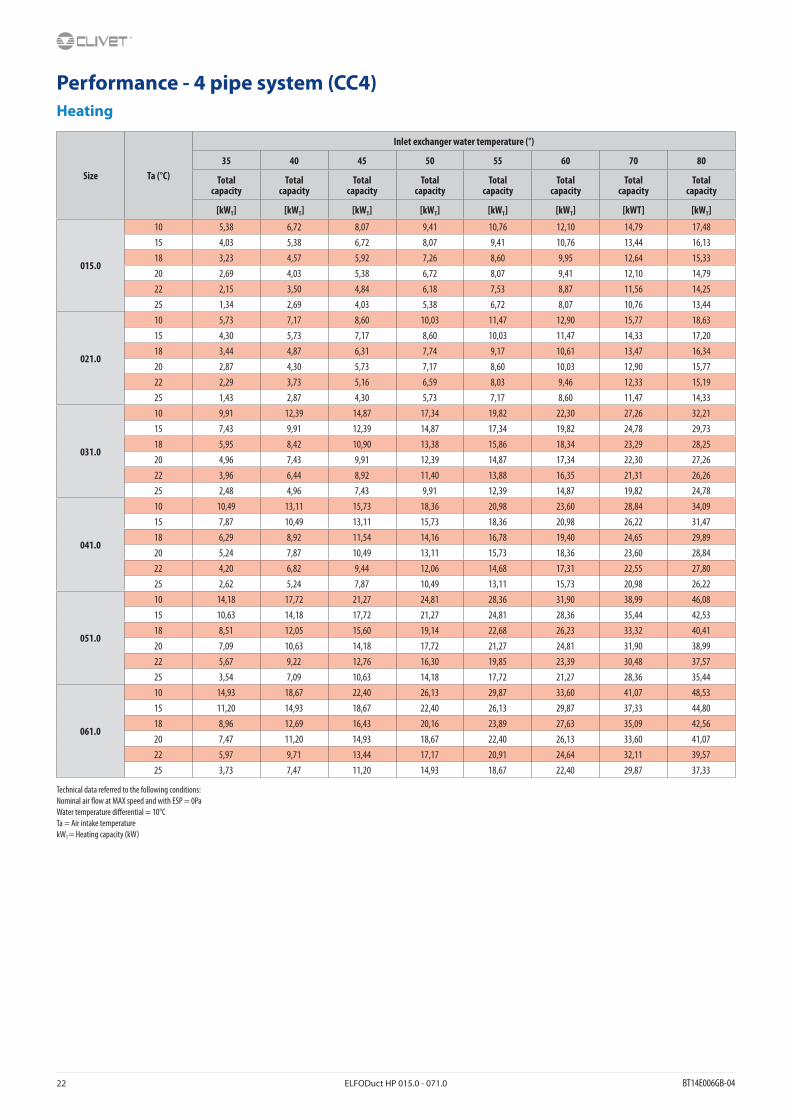
Performance - 4 pipe system (CC4)Heating
Size Ta (°C)
Inlet exchanger water temperature (°)
35 40 45 50 55 60 70 80
Total capacity
Total capacity
Total capacity
Total capacity
Total capacity
Total capacity
Total capacity
Total capacity
[kWT] [kWT] [kWT] [kWT] [kWT] [kWT] [kWT] [kWT]
015.0
10 5,38 6,72 8,07 9,41 10,76 12,10 14,79 17,4815 4,03 5,38 6,72 8,07 9,41 10,76 13,44 16,1318 3,23 4,57 5,92 7,26 8,60 9,95 12,64 15,3320 2,69 4,03 5,38 6,72 8,07 9,41 12,10 14,7922 2,15 3,50 4,84 6,18 7,53 8,87 11,56 14,2525 1,34 2,69 4,03 5,38 6,72 8,07 10,76 13,44
021.0
10 5,73 7,17 8,60 10,03 11,47 12,90 15,77 18,6315 4,30 5,73 7,17 8,60 10,03 11,47 14,33 17,2018 3,44 4,87 6,31 7,74 9,17 10,61 13,47 16,3420 2,87 4,30 5,73 7,17 8,60 10,03 12,90 15,7722 2,29 3,73 5,16 6,59 8,03 9,46 12,33 15,1925 1,43 2,87 4,30 5,73 7,17 8,60 11,47 14,33
031.0
10 9,91 12,39 14,87 17,34 19,82 22,30 27,26 32,2115 7,43 9,91 12,39 14,87 17,34 19,82 24,78 29,7318 5,95 8,42 10,90 13,38 15,86 18,34 23,29 28,2520 4,96 7,43 9,91 12,39 14,87 17,34 22,30 27,2622 3,96 6,44 8,92 11,40 13,88 16,35 21,31 26,2625 2,48 4,96 7,43 9,91 12,39 14,87 19,82 24,78
041.0
10 10,49 13,11 15,73 18,36 20,98 23,60 28,84 34,0915 7,87 10,49 13,11 15,73 18,36 20,98 26,22 31,4718 6,29 8,92 11,54 14,16 16,78 19,40 24,65 29,8920 5,24 7,87 10,49 13,11 15,73 18,36 23,60 28,8422 4,20 6,82 9,44 12,06 14,68 17,31 22,55 27,8025 2,62 5,24 7,87 10,49 13,11 15,73 20,98 26,22
051.0
10 14,18 17,72 21,27 24,81 28,36 31,90 38,99 46,0815 10,63 14,18 17,72 21,27 24,81 28,36 35,44 42,5318 8,51 12,05 15,60 19,14 22,68 26,23 33,32 40,4120 7,09 10,63 14,18 17,72 21,27 24,81 31,90 38,9922 5,67 9,22 12,76 16,30 19,85 23,39 30,48 37,5725 3,54 7,09 10,63 14,18 17,72 21,27 28,36 35,44
061.0
10 14,93 18,67 22,40 26,13 29,87 33,60 41,07 48,5315 11,20 14,93 18,67 22,40 26,13 29,87 37,33 44,8018 8,96 12,69 16,43 20,16 23,89 27,63 35,09 42,5620 7,47 11,20 14,93 18,67 22,40 26,13 33,60 41,0722 5,97 9,71 13,44 17,17 20,91 24,64 32,11 39,5725 3,73 7,47 11,20 14,93 18,67 22,40 29,87 37,33
Technical data referred to the following conditions:Nominal air �ow at MAX speed and with ESP = 0PaWater temperature di�erential = 10°CTa = Air intake temperaturekWT = Heating capacity (kW)
BT14E006GB-04 ELFODuct HP 015.0 - 071.0 23
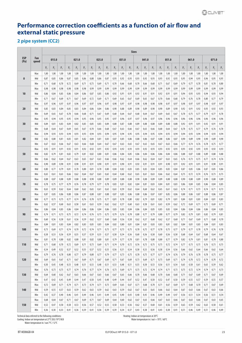
Performance correction coe�cients as a function of air �ow and external static pressure2 pipe system (CC2)
ESP(Pa)
Fan speed
Sizes
015.0 021.0 025.0 031.0 041.0 051.0 061.0 071.0
PF PS PT PF PS PT PF PS PT PF PS PT PF PS PT PF PS PT PF PS PT PF PS PT
0
Max 1,00 1,00 1,00 1,00 1,00 1,00 1,00 1,00 1,00 1,00 1,00 1,00 1,00 1,00 1,00 1,00 1,00 1,00 1,00 1,00 1,00 1,00 1,00 1,00
Mid 0,87 0,85 0,86 0,87 0,85 0,86 0,88 0,86 0,87 0,93 0,92 0,93 0,93 0,92 0,93 0,93 0,92 0,93 0,95 0,94 0,95 0,96 0,95 0,95
Min 0,71 0,68 0,70 0,72 0,69 0,71 0,73 0,69 0,71 0,70 0,66 0,68 0,70 0,66 0,68 0,71 0,67 0,69 0,79 0,77 0,78 0,81 0,78 0,80
10
Max 0,98 0,98 0,98 0,98 0,98 0,98 0,99 0,99 0,99 0,99 0,99 0,99 0,99 0,99 0,99 0,99 0,99 0,99 0,99 0,99 0,99 0,99 0,99 0,99
Mid 0,86 0,84 0,85 0,86 0,84 0,86 0,87 0,85 0,86 0,92 0,91 0,91 0,92 0,91 0,91 0,92 0,91 0,91 0,94 0,93 0,93 0,94 0,93 0,94
Min 0,71 0,67 0,69 0,71 0,67 0,69 0,72 0,69 0,71 0,69 0,65 0,67 0,69 0,65 0,67 0,70 0,66 0,68 0,79 0,76 0,78 0,80 0,77 0,79
20
Max 0,97 0,96 0,97 0,97 0,96 0,97 0,97 0,96 0,97 0,98 0,97 0,97 0,98 0,98 0,98 0,98 0,97 0,97 0,98 0,97 0,97 0,98 0,97 0,97
Mid 0,85 0,83 0,84 0,85 0,83 0,84 0,86 0,84 0,86 0,90 0,88 0,89 0,90 0,89 0,90 0,90 0,89 0,90 0,92 0,91 0,92 0,93 0,92 0,93
Min 0,69 0,65 0,67 0,70 0,66 0,68 0,71 0,67 0,69 0,68 0,64 0,67 0,68 0,64 0,67 0,69 0,65 0,67 0,78 0,75 0,77 0,79 0,77 0,78
30
Max 0,95 0,94 0,95 0,95 0,94 0,95 0,96 0,95 0,95 0,97 0,96 0,97 0,97 0,96 0,97 0,96 0,96 0,96 0,96 0,96 0,96 0,96 0,96 0,96
Mid 0,84 0,81 0,83 0,84 0,82 0,83 0,85 0,83 0,84 0,88 0,87 0,88 0,89 0,88 0,88 0,89 0,88 0,88 0,92 0,91 0,91 0,92 0,91 0,91
Min 0,68 0,64 0,67 0,69 0,65 0,67 0,70 0,66 0,68 0,67 0,63 0,66 0,67 0,63 0,66 0,68 0,64 0,67 0,78 0,75 0,77 0,79 0,76 0,78
40
Max 0,94 0,93 0,93 0,94 0,93 0,93 0,94 0,93 0,94 0,95 0,94 0,95 0,95 0,94 0,95 0,94 0,93 0,94 0,94 0,93 0,94 0,94 0,93 0,94
Mid 0,82 0,80 0,81 0,83 0,81 0,82 0,84 0,81 0,83 0,87 0,85 0,86 0,88 0,86 0,87 0,88 0,86 0,87 0,90 0,89 0,90 0,90 0,89 0,90
Min 0,67 0,63 0,66 0,67 0,63 0,66 0,68 0,64 0,67 0,67 0,63 0,65 0,67 0,63 0,65 0,67 0,63 0,66 0,77 0,74 0,76 0,78 0,75 0,77
50
Max 0,92 0,91 0,91 0,92 0,91 0,92 0,92 0,91 0,92 0,93 0,92 0,93 0,93 0,92 0,93 0,93 0,92 0,93 0,93 0,92 0,93 0,93 0,92 0,93
Mid 0,82 0,79 0,81 0,82 0,79 0,81 0,82 0,80 0,81 0,86 0,84 0,85 0,86 0,84 0,86 0,86 0,84 0,86 0,88 0,87 0,88 0,89 0,88 0,88
Min 0,66 0,62 0,64 0,67 0,63 0,65 0,67 0,63 0,66 0,66 0,62 0,64 0,66 0,62 0,64 0,67 0,63 0,65 0,76 0,73 0,75 0,77 0,74 0,76
60
Max 0,90 0,89 0,90 0,91 0,90 0,91 0,91 0,90 0,91 0,91 0,90 0,91 0,92 0,91 0,91 0,91 0,90 0,91 0,92 0,91 0,91 0,91 0,90 0,91
Mid 0,80 0,77 0,79 0,81 0,78 0,80 0,81 0,78 0,80 0,84 0,82 0,83 0,85 0,83 0,84 0,85 0,83 0,84 0,87 0,85 0,86 0,87 0,85 0,86
Min 0,65 0,61 0,63 0,66 0,62 0,64 0,67 0,63 0,65 0,64 0,60 0,62 0,65 0,61 0,63 0,66 0,62 0,64 0,75 0,72 0,74 0,76 0,73 0,75
70
Max 0,88 0,87 0,88 0,89 0,88 0,88 0,90 0,88 0,89 0,89 0,88 0,88 0,90 0,88 0,89 0,89 0,88 0,88 0,90 0,88 0,89 0,90 0,88 0,89
Mid 0,78 0,75 0,77 0,79 0,76 0,78 0,79 0,77 0,78 0,83 0,81 0,82 0,84 0,81 0,83 0,84 0,81 0,83 0,86 0,84 0,85 0,86 0,84 0,85
Min 0,63 0,59 0,62 0,64 0,60 0,62 0,65 0,61 0,63 0,63 0,59 0,62 0,64 0,60 0,62 0,65 0,61 0,63 0,74 0,71 0,73 0,74 0,71 0,73
80
Max 0,87 0,85 0,86 0,88 0,86 0,87 0,88 0,87 0,88 0,87 0,85 0,86 0,88 0,86 0,87 0,87 0,85 0,86 0,88 0,86 0,87 0,88 0,86 0,87
Mid 0,77 0,73 0,75 0,77 0,74 0,76 0,78 0,75 0,77 0,81 0,78 0,80 0,82 0,79 0,81 0,82 0,79 0,81 0,84 0,81 0,83 0,84 0,81 0,83
Min 0,62 0,57 0,60 0,63 0,58 0,61 0,63 0,59 0,62 0,62 0,57 0,60 0,63 0,58 0,61 0,63 0,59 0,62 0,72 0,69 0,71 0,73 0,69 0,71
90
Max 0,86 0,84 0,85 0,86 0,84 0,86 0,86 0,84 0,86 0,85 0,83 0,84 0,86 0,84 0,85 0,85 0,83 0,84 0,86 0,84 0,86 0,86 0,84 0,85
Mid 0,74 0,71 0,73 0,75 0,72 0,74 0,76 0,73 0,75 0,79 0,76 0,78 0,80 0,77 0,79 0,80 0,77 0,79 0,82 0,79 0,81 0,82 0,79 0,81
Min 0,60 0,56 0,58 0,61 0,56 0,59 0,62 0,57 0,60 0,60 0,56 0,58 0,62 0,57 0,60 0,62 0,57 0,60 0,71 0,67 0,69 0,71 0,68 0,70
100
Max 0,84 0,81 0,83 0,84 0,82 0,83 0,85 0,83 0,84 0,82 0,80 0,81 0,84 0,81 0,83 0,83 0,81 0,82 0,84 0,81 0,83 0,84 0,81 0,83
Mid 0,73 0,69 0,71 0,74 0,70 0,72 0,74 0,71 0,73 0,77 0,73 0,75 0,78 0,75 0,77 0,78 0,75 0,77 0,79 0,77 0,78 0,79 0,76 0,78
Min 0,58 0,53 0,56 0,59 0,55 0,57 0,59 0,55 0,57 0,58 0,54 0,56 0,60 0,56 0,58 0,60 0,56 0,58 0,68 0,64 0,67 0,68 0,64 0,67
110
Max 0,81 0,78 0,80 0,82 0,80 0,81 0,82 0,80 0,81 0,79 0,77 0,78 0,81 0,78 0,80 0,80 0,77 0,79 0,82 0,79 0,81 0,81 0,78 0,80
Mid 0,71 0,68 0,70 0,72 0,69 0,71 0,73 0,69 0,71 0,74 0,70 0,72 0,76 0,73 0,75 0,75 0,72 0,74 0,77 0,73 0,75 0,76 0,73 0,75
Min 0,54 0,49 0,52 0,57 0,52 0,55 0,57 0,52 0,55 0,56 0,51 0,54 0,58 0,53 0,56 0,58 0,54 0,56 0,66 0,62 0,64 0,66 0,62 0,64
120
Max 0,79 0,76 0,78 0,80 0,77 0,79 0,80 0,77 0,79 0,77 0,73 0,75 0,78 0,75 0,77 0,77 0,74 0,76 0,79 0,76 0,78 0,78 0,75 0,77
Mid 0,69 0,65 0,67 0,71 0,67 0,69 0,71 0,67 0,69 0,71 0,67 0,69 0,73 0,69 0,71 0,73 0,69 0,71 0,74 0,70 0,72 0,74 0,70 0,72
Min 0,50 0,45 0,48 0,53 0,48 0,51 0,53 0,48 0,51 0,53 0,48 0,51 0,55 0,50 0,53 0,56 0,51 0,54 0,63 0,58 0,61 0,63 0,59 0,62
130
Max 0,76 0,73 0,75 0,77 0,74 0,76 0,77 0,74 0,76 0,73 0,69 0,71 0,75 0,72 0,74 0,74 0,71 0,73 0,75 0,72 0,74 0,74 0,71 0,73
Mid 0,64 0,60 0,62 0,67 0,63 0,66 0,67 0,63 0,66 0,67 0,63 0,66 0,70 0,66 0,68 0,70 0,66 0,68 0,71 0,67 0,69 0,71 0,67 0,69
Min 0,47 0,42 0,45 0,49 0,44 0,47 0,50 0,45 0,48 0,49 0,44 0,47 0,52 0,47 0,50 0,52 0,47 0,50 0,59 0,55 0,57 0,59 0,55 0,57
140
Max 0,72 0,69 0,71 0,74 0,71 0,73 0,74 0,71 0,73 0,69 0,65 0,67 0,71 0,68 0,70 0,71 0,67 0,69 0,71 0,68 0,70 0,71 0,67 0,69
Mid 0,59 0,55 0,57 0,63 0,59 0,62 0,63 0,59 0,62 0,63 0,59 0,62 0,67 0,63 0,65 0,66 0,62 0,64 0,67 0,63 0,66 0,67 0,63 0,66
Min 0,42 0,37 0,40 0,46 0,41 0,44 0,46 0,41 0,44 0,45 0,40 0,43 0,48 0,43 0,46 0,49 0,44 0,47 0,56 0,51 0,54 0,56 0,51 0,54
150
Max 0,68 0,64 0,67 0,71 0,67 0,69 0,71 0,67 0,69 0,64 0,60 0,62 0,67 0,63 0,66 0,67 0,63 0,66 0,67 0,63 0,66 0,67 0,63 0,65
Mid 0,52 0,47 0,50 0,58 0,53 0,56 0,57 0,52 0,55 0,58 0,53 0,56 0,62 0,57 0,60 0,61 0,56 0,59 0,63 0,59 0,62 0,63 0,58 0,61
Min 0,36 0,30 0,33 0,41 0,36 0,39 0,41 0,36 0,39 0,39 0,34 0,37 0,43 0,38 0,41 0,43 0,38 0,41 0,51 0,46 0,49 0,51 0,46 0,49
Technical data referred to the following conditions:Cooling: Indoor air temperature at 27°C D.B./19°C W.B Water temperature in / out 7°C / 12°C
Heating: Indoor air temperature at 20°C Water temperature in / out = 70°C / 60°C

24 ELFODuct HP 015.0 - 071.0 BT14E006GB-04
Performance correction coe�cients as a function of air �ow and external static pressure4 pipe system (CC4)
ESP (Pa)
Fan speed
Sizes
015.0 021.0 031.0 041.0 051.0 061.0
PF PS PT PF PS PT PF PS PT PF PS PT PF PS PT PF PS PT
0
Max 1,00 1,00 1,00 1,00 1,00 1,00 1,00 1,00 1,00 1,00 1,00 1,00 1,00 1,00 1,00 1,00 1,00 1,00
Mid 0,88 0,87 0,88 0,89 0,88 0,88 0,92 0,91 0,92 0,93 0,92 0,93 0,96 0,95 0,95 0,96 0,96 0,96
Min 0,73 0,69 0,71 0,74 0,70 0,72 0,71 0,67 0,69 0,71 0,68 0,70 0,82 0,79 0,81 0,82 0,80 0,81
10
Max 0,98 0,98 0,98 0,99 0,99 0,99 0,99 0,99 0,99 0,99 0,99 0,99 0,99 0,99 0,99 0,99 0,99 0,99
Mid 0,87 0,85 0,86 0,88 0,86 0,87 0,91 0,90 0,91 0,92 0,91 0,91 0,94 0,93 0,94 0,94 0,93 0,94
Min 0,72 0,69 0,71 0,73 0,69 0,71 0,71 0,67 0,69 0,71 0,67 0,69 0,81 0,78 0,80 0,82 0,79 0,81
20
Max 0,97 0,96 0,97 0,97 0,96 0,97 0,97 0,96 0,97 0,97 0,96 0,97 0,97 0,96 0,97 0,98 0,97 0,97
Mid 0,86 0,84 0,86 0,87 0,85 0,86 0,90 0,89 0,90 0,90 0,89 0,90 0,93 0,92 0,93 0,93 0,92 0,93
Min 0,71 0,67 0,69 0,71 0,68 0,70 0,70 0,66 0,68 0,70 0,66 0,68 0,80 0,77 0,79 0,81 0,78 0,80
30
Max 0,96 0,95 0,95 0,96 0,95 0,95 0,95 0,94 0,95 0,96 0,95 0,95 0,96 0,95 0,95 0,96 0,95 0,95
Mid 0,85 0,83 0,84 0,86 0,84 0,85 0,89 0,88 0,88 0,89 0,88 0,88 0,92 0,91 0,91 0,92 0,91 0,91
Min 0,70 0,66 0,68 0,71 0,67 0,69 0,68 0,64 0,67 0,69 0,65 0,67 0,79 0,77 0,78 0,80 0,77 0,79
40
Max 0,94 0,93 0,93 0,94 0,93 0,94 0,94 0,93 0,93 0,94 0,93 0,93 0,94 0,93 0,93 0,94 0,93 0,94
Mid 0,84 0,81 0,83 0,84 0,82 0,83 0,88 0,86 0,87 0,88 0,87 0,88 0,90 0,88 0,89 0,90 0,89 0,90
Min 0,68 0,64 0,67 0,69 0,65 0,67 0,67 0,63 0,66 0,68 0,64 0,67 0,79 0,76 0,78 0,79 0,77 0,78
50
Max 0,92 0,91 0,92 0,93 0,92 0,93 0,92 0,91 0,91 0,92 0,91 0,91 0,92 0,91 0,92 0,92 0,91 0,92
Mid 0,83 0,81 0,82 0,83 0,81 0,82 0,86 0,84 0,85 0,86 0,84 0,86 0,88 0,87 0,88 0,89 0,88 0,88
Min 0,67 0,63 0,66 0,68 0,64 0,67 0,67 0,63 0,65 0,67 0,63 0,66 0,77 0,74 0,76 0,78 0,75 0,77
60
Max 0,91 0,90 0,91 0,92 0,91 0,91 0,90 0,88 0,89 0,90 0,89 0,90 0,90 0,89 0,90 0,91 0,90 0,91
Mid 0,81 0,78 0,80 0,82 0,79 0,81 0,84 0,82 0,83 0,85 0,83 0,84 0,86 0,84 0,86 0,87 0,85 0,86
Min 0,66 0,62 0,64 0,67 0,63 0,65 0,66 0,62 0,64 0,67 0,63 0,65 0,76 0,73 0,75 0,77 0,73 0,75
70
Max 0,89 0,88 0,88 0,90 0,88 0,89 0,88 0,86 0,87 0,88 0,87 0,88 0,89 0,88 0,88 0,90 0,88 0,89
Mid 0,79 0,76 0,78 0,80 0,77 0,79 0,82 0,80 0,81 0,84 0,81 0,83 0,84 0,82 0,83 0,86 0,84 0,85
Min 0,64 0,60 0,62 0,65 0,61 0,63 0,64 0,60 0,62 0,66 0,62 0,64 0,74 0,71 0,73 0,75 0,72 0,74
80
Max 0,88 0,86 0,87 0,88 0,87 0,88 0,86 0,84 0,85 0,86 0,84 0,86 0,86 0,84 0,86 0,87 0,85 0,86
Mid 0,77 0,74 0,76 0,78 0,75 0,77 0,81 0,78 0,80 0,82 0,79 0,81 0,82 0,80 0,81 0,83 0,81 0,82
Min 0,63 0,58 0,61 0,64 0,60 0,62 0,63 0,58 0,61 0,64 0,60 0,62 0,73 0,69 0,71 0,74 0,70 0,72
90
Max 0,86 0,84 0,85 0,87 0,85 0,86 0,84 0,81 0,83 0,84 0,82 0,83 0,84 0,82 0,83 0,85 0,83 0,84
Mid 0,76 0,73 0,75 0,77 0,73 0,75 0,79 0,76 0,78 0,79 0,77 0,78 0,79 0,77 0,78 0,81 0,78 0,80
Min 0,61 0,56 0,59 0,63 0,58 0,61 0,61 0,56 0,59 0,63 0,58 0,61 0,70 0,66 0,68 0,71 0,68 0,70
100
Max 0,84 0,81 0,83 0,85 0,83 0,84 0,81 0,78 0,80 0,82 0,80 0,81 0,82 0,79 0,81 0,82 0,80 0,81
Mid 0,74 0,71 0,73 0,75 0,72 0,74 0,76 0,73 0,75 0,77 0,74 0,76 0,77 0,74 0,76 0,79 0,76 0,78
Min 0,58 0,54 0,56 0,60 0,56 0,58 0,59 0,55 0,57 0,61 0,56 0,59 0,67 0,63 0,65 0,69 0,65 0,67
110
Max 0,81 0,78 0,80 0,82 0,80 0,81 0,78 0,75 0,77 0,79 0,77 0,78 0,79 0,76 0,78 0,80 0,77 0,79
Mid 0,72 0,69 0,71 0,73 0,69 0,71 0,73 0,69 0,71 0,75 0,72 0,74 0,74 0,71 0,73 0,76 0,73 0,75
Min 0,55 0,50 0,53 0,57 0,52 0,55 0,57 0,52 0,55 0,58 0,54 0,56 0,64 0,60 0,62 0,66 0,62 0,64
120
Max 0,78 0,75 0,77 0,80 0,77 0,79 0,75 0,72 0,74 0,77 0,73 0,75 0,75 0,72 0,74 0,77 0,73 0,75
Mid 0,68 0,64 0,67 0,71 0,67 0,69 0,71 0,67 0,69 0,72 0,69 0,71 0,71 0,68 0,70 0,74 0,70 0,72
Min 0,51 0,46 0,49 0,53 0,48 0,51 0,54 0,49 0,52 0,56 0,51 0,54 0,61 0,56 0,59 0,63 0,59 0,62
130
Max 0,75 0,72 0,74 0,77 0,74 0,76 0,71 0,68 0,70 0,74 0,70 0,72 0,71 0,68 0,70 0,74 0,70 0,72
Mid 0,64 0,60 0,62 0,67 0,63 0,66 0,67 0,63 0,65 0,69 0,65 0,67 0,68 0,64 0,67 0,71 0,67 0,69
Min 0,48 0,43 0,46 0,50 0,45 0,48 0,50 0,45 0,48 0,52 0,47 0,50 0,57 0,52 0,55 0,59 0,55 0,57
140
Max 0,72 0,69 0,71 0,74 0,71 0,73 0,67 0,63 0,66 0,70 0,66 0,68 0,67 0,63 0,66 0,71 0,67 0,69
Mid 0,58 0,54 0,56 0,63 0,58 0,61 0,62 0,57 0,60 0,65 0,61 0,63 0,63 0,59 0,62 0,67 0,63 0,65
Min 0,43 0,38 0,41 0,47 0,42 0,45 0,45 0,40 0,43 0,49 0,44 0,47 0,52 0,47 0,50 0,56 0,51 0,54
150
Max 0,64 0,60 0,62 0,71 0,67 0,69 0,62 0,57 0,60 0,66 0,62 0,64 0,63 0,58 0,61 0,67 0,63 0,65
Mid 0,51 0,46 0,49 0,57 0,52 0,55 0,56 0,51 0,54 0,60 0,56 0,58 0,58 0,54 0,56 0,62 0,57 0,60
Min 0,37 0,32 0,35 0,41 0,36 0,39 0,39 0,34 0,37 0,43 0,38 0,41 0,47 0,42 0,45 0,52 0,47 0,50
Technical data referred to the following conditions:Cooling: Indoor air temperature at 27°C D.B./19°C W.B Water temperature in / out 7°C / 12°C
Heating: Indoor air temperature at 20°C Water temperature in / out = 70°C / 60°C

BT14E006GB-04 ELFODuct HP 015.0 - 071.0 25
Exchanger pressure drops
2 pipe system (CC2)
4 pipe system (CC4)
Q = Water �ow rate (l/s)DP = Pressure drops [kPa]
Q = Water �ow rate (l/s)DP = Pressure drops [kPa]

26 ELFODuct HP 015.0 - 071.0 BT14E006GB-04
Con�guration optionsTRM - Terminal block with minimum water temperature clickson“Mammoth” type terminal board (min. 7 poles) IP20 with minimum hot water temperature thermostat (T. SET = 32°C).This function disable the fan operation when, in heating mode, the water on the coil is not hot enough.Function to prevent ventilation, of cold air in the room (because the water is too cold), which in winter it can be particularly annoying.The probe which measures the minimum temperature is usually installed in contact with the heating coil, but according to the controllers maybe required the intallation on the inlet pipe unit (before any possible valve).
The “minimum hot water temperature” works only in heating mode. In cooling it is by-passed.
If electronic CTS (CLIVET TALK TERMINAL SPACE) is present, isn’t longer necessary this option because already included.
TRP - Terminal block with closing cover IP40Terminal block type “mamut” (min. 7 poles) with closing cover IP40.
If electronic CTS (CLIVET TALK TERMINAL SPACE) is present, isn’t longer necessary this option because already included.
TRMP - Terminal block with closing cover IP40 and minimum water temperature clicksonTerminal block type “mamut” (min. 7 poles) with closing cover IP40 and minimum water temperature clickson.
If electronic CTS (CLIVET TALK TERMINAL SPACE) is present, isn’t longer necessary this option because already included.
CTSP1 - CLIVET TALK TERMINAL SPACE electronics with RS485 Modbus serial port
This is a card for control of the unit which, in addition to basic functions, allows it to be connected to a network of similar units managed centrally by ELFOControl or B.M.S.
This type of electronic card is suited for communicating via RS485 if connected to SP1 devices.
The microprocessor control installed in the unit receives operating settings from one of the following thermostats:
• HID-T2 - Electronic room control for wall installation
• HID-T3 - Electronic room control for wall installation with humidity probe
With CTSP1 electronics is provided also a return air probe for the reading of the room temperature. By default is expected that the air probe of the room thermostat (HIDT...), when present, is priority respect to the return air probe, even if it is connected. When there isn’t room thermostat, the unit adjusts on its return air probe. Through the setting of a parameter it’s possible that this priority can be reversed and therefore the reading of temperature by the return air probe is priority respect to the air probe of the room thermostat (HIDT...), even though this is simultaneously connected.When it isn’t present, the return air probe of the unit will adjust on the value detected by the thermostat.
Its functionalities are:
• control of minimum temperature of system water temperature
• Control of manual or automatic speed fan
• control of on/o� water valve
• control card of 0-10V valve and fan through the additional card CPVM
• digital input for remote on/o� function or winter/summer
• fan control / fresh air damper actuator
• on/o� control of electrical heating element or cumulative alarm relay.
The serial port with MODBUS protocol. Allows the cable connection betweem the units and the ELFOControl or B.M.S. It allow to create mini networks (a single HIDT... thermostat that controls up to 9 units).
CPVM - Control additional card of 0-10V valve and EC fan (available only with options: CTSP1)Control card of fan and 0-10V valve.
(MV) Fan motor(TM) Minimum water temperature clickson
(MV) Fan motor(TM) Minimum water temperature clickson
(MV) Fan motor

BT14E006GB-04 ELFODuct HP 015.0 - 071.0 27
VEC - High e�ciency EC fan (available with options: TR, TRM, TRP, TRMP, CTSP1 + CPVM)The ELFODuct HP series can be con�gured with an innovative DC Brushless motor fan and ensures reduced consumption thanks to the modulation of the ventilation.
The air �ow can be varied continuously with a 0-10V signal.
The estreme e�ciency, also at low speed, makes possible a great reduction in electric consumption and the operating costs in comparison to a traditional fan coil with AC motor.
The main advantages are:
• Large reduction in energy consumption, thanks to an optimal response to the thermal load of the environment during every moment of the day
• Operating silence at all rotation speeds
• Ability to operate at any rotation speed
RE700 - 0.7 kW integrated electric heater with safety thermostat and power electric panel
RE1000 - 1.0 kW integrated electric heater with safety thermostat and power electric panel
RE1500 - 1.5 kW integrated electric heater with safety thermostat and power electric panel
RE2000 - 2.0 kW integrated electric heater with safety thermostat and power electric panelSingle-stage electrical heater integrated inside the unit with automatic reset safety thermostat (without power relay) and power electric panel for heaters supplied installed external to the section containing the electrical heaters, also including the terminal board wiring.
Heating element for air insertable any size, checked for compatibility of the dimensions.
Main technical speci�cations of the electric heaters
Model Compatibility Pwer supply
Heating capacity
Current input (Max)
Dimensions (Lenght x Height x Depth)
RE700 All sizes 230Vac 700W 3,05A 400x115x30mm
RE1000 All sizes 230Vac 1000W 4,35A 500x115x30mm
RE1500 All sizes 230Vac 1500W 6,53A 750x115x30mm
RE2000 All sizes 230Vac 2000W 8,70A 950x115x30mm

28 ELFODuct HP 015.0 - 071.0 BT14E006GB-04
2V2 - on/o� 2-way valve kit for 2 pipe system (available only with options: CC2)
2V4 - on/o� 2-way valve kit for 4 pipe system (available only with options: CC4)
3V2 - Three-way valve kit for 2 pipe system type “on/o�” (available only with options: CC2)
3V4 - Three-way valve kit for 4 pipe system type “on/o�” (available only with options: CC4)
10V2 - 0-10V 3 way valve kit for 2 pipe system (available only with options: CC2)
10V4 - 0-10V 3 way valve kit for 4 pipe system (available only with options: CC4)ON/OFF 2 or 3-way valve kit (power 230Vac) complete with thermoelectric actuator or modulating 0-10V 3-way valve kit (power 24Vac), suitable for all versions (horizontal and vertical units) and for units with connections either on right or left.
Technical data
• DN = 3/4” M
• PN = 16 bar
• Kv = 2,5 (CC2: size 015.0 - 021.0 - 025.0 / CC4: size 015.0 - 021.0); 4 (CC2: size 031.0 - 041.0 - 051.0 / CC4: size 031.0 - 041.0); 6 (CC2: size 061.0 - 071.0 / CC4: size 051.0 - 061.0)
• ΔP = 70 kPa.
Accessory also available separately supplied
Pressure drop 2V2 2V4
3V2 o 10V2 3V4 o 10V4
Q = Water �ow rate (l/s)DP = Pressure drop [kPa]
CDP - Condensate pumpCondensate pump provided with 8A (250V) alarm contact, suitable for all vertical versions (INV) and horizontal version (INH).
Water �ow:
• 8 l/h con 0 m.w.c. (max);
• 6,5 l/h con 1 m.w.c.;
• 4 l/h con 3 m.w.c.;
• 0 l/h con 6 m.w.c.
Accessory also available separately supplied
BRO - Auxiliary drain pan in galvanized steel with thermal insulation (available only with options: INH)The auxiliary drain pan for horizontal version makes it possible to collect the condensation of the unit’s connection tubes and valves.
Realized of galvanized steel and internal thermal-acoustic insulation (class M1).
This accessory is suitable for:
• installation on all sizes;
• for units with connections either on right or left.
Accessory also available separately supplied
BT14E006GB-04 ELFODuct HP 015.0 - 071.0 29
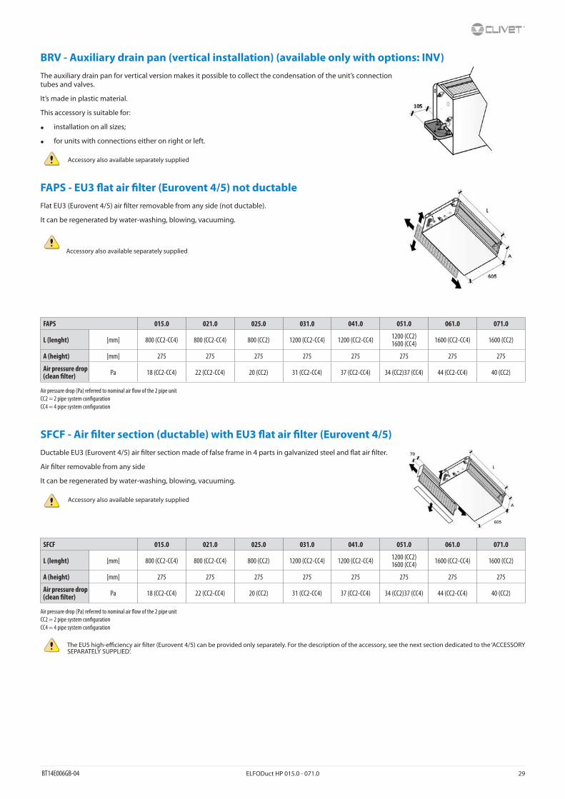
BRV - Auxiliary drain pan (vertical installation) (available only with options: INV)The auxiliary drain pan for vertical version makes it possible to collect the condensation of the unit’s connection tubes and valves.
It’s made in plastic material.
This accessory is suitable for:
• installation on all sizes;
• for units with connections either on right or left.
Accessory also available separately supplied
FAPS - EU3 �at air �lter (Eurovent 4/5) not ductableFlat EU3 (Eurovent 4/5) air �lter removable from any side (not ductable).
It can be regenerated by water-washing, blowing, vacuuming.
Accessory also available separately supplied
FAPS 015.0 021.0 025.0 031.0 041.0 051.0 061.0 071.0
L (lenght) [mm] 800 (CC2-CC4) 800 (CC2-CC4) 800 (CC2) 1200 (CC2-CC4) 1200 (CC2-CC4) 1200 (CC2)1600 (CC4) 1600 (CC2-CC4) 1600 (CC2)
A (height) [mm] 275 275 275 275 275 275 275 275
Air pressure drop (clean �lter) Pa 18 (CC2-CC4) 22 (CC2-CC4) 20 (CC2) 31 (CC2-CC4) 37 (CC2-CC4) 34 (CC2)37 (CC4) 44 (CC2-CC4) 40 (CC2)
Air pressure drop (Pa) referred to nominal air �ow of the 2 pipe unitCC2 = 2 pipe system con�gurationCC4 = 4 pipe system con�guration
SFCF - Air �lter section (ductable) with EU3 �at air �lter (Eurovent 4/5)Ductable EU3 (Eurovent 4/5) air �lter section made of false frame in 4 parts in galvanized steel and �at air �lter.
Air �lter removable from any side
It can be regenerated by water-washing, blowing, vacuuming.
Accessory also available separately supplied
SFCF 015.0 021.0 025.0 031.0 041.0 051.0 061.0 071.0
L (lenght) [mm] 800 (CC2-CC4) 800 (CC2-CC4) 800 (CC2) 1200 (CC2-CC4) 1200 (CC2-CC4) 1200 (CC2)1600 (CC4) 1600 (CC2-CC4) 1600 (CC2)
A (height) [mm] 275 275 275 275 275 275 275 275
Air pressure drop (clean �lter) Pa 18 (CC2-CC4) 22 (CC2-CC4) 20 (CC2) 31 (CC2-CC4) 37 (CC2-CC4) 34 (CC2)37 (CC4) 44 (CC2-CC4) 40 (CC2)
Air pressure drop (Pa) referred to nominal air �ow of the 2 pipe unitCC2 = 2 pipe system con�gurationCC4 = 4 pipe system con�guration
The EU5 high-e�ciency air �lter (Eurovent 4/5) can be provided only separately. For the description of the accessory, see the next section dedicated to the ‘ACCESSORY SEPARATELY SUPPLIED’.

30 ELFODuct HP 015.0 - 071.0 BT14E006GB-04
Accessories separately suppliedHIDE2X - Remote control with E/I + 3V + on/o� for wall installation
HID-E2 electro mechanical room thermostat for wall installation
It allows:
• setting the desired temperature (10-30°C)
• selection of the 3 speeds (MIN - MED - MAX)
• ON/OFF
• manual Summer / Winter change
• continuous or thermostat-based ventilation
• control of on/o� water valve
It can be connected to the remote air probe (PTABX).
The hot water minimum temperature Clickson can be connected.
Dimensions: 184x82x27 mm
HIDE3X - Plurifunctional remote control for wall installation
HID-E3 electro mechanical room thermostat for wall installation
It allows:
• automatic fan speed adjustment (MIN - MED - MAX)
• silent operation (minimum fan speed)
• ON/OFF
• ambient temperature adjustment via the control knob: the knob’s central position corresponds to the comfort condition (20°C in heating mode, 24°C in cooling mode). The temperature can be changed by +/- 5°C in relation to the comfort condition by turning the knob
• automatic selection of the Summer/Winter season: the heating or cooling mode is selected automatically by detecting the water temperature supplied to the fan-coil (water temperature below 17°C=operation in cooling mode, water temperature above 21°C=operation in heating mode)
• Hot Start function: in heating mode the fan does not start until the thermal coil is not hot enough
• destrati�cation cycle
• dirty �lter warning
• minimum water temperature probe
Dimensions: 184x82x27 mm
HIDE4X - Plurifunctional room control for 0-10V valves
Electro-mechanical room thermostat HID-E4 for wall mounting with proportional outlets for 2 or 4 pipe systems.
It allows:
• power supply 24V
• setting the desired temperature (10-30°C)
• manual Summer / Winter change
• fan speed selection (MIN - MED - MAX)
• control 0-10V coil valves for hot/cold water for thermostat controlled 2 or 4 pipe systems with adjustable working range and neutral zone (respectively 1-5°C and 1-4°C)
Set up for connection of remote air probe (PTABX).
Dimensions: 184x82x27 mm

BT14E006GB-04 ELFODuct HP 015.0 - 071.0 31
HIDT2X - HID-T2 electronic room controlThe HID-T2 room thermostat makes it possible to interface with the control module of units equipped with CLIVET TALK TERMINAL SPACE electronics (CTSP1) and to manage one or more thermostat units.
The room thermostat allows the following functions:
• setting of the desidered temperature
• selection of the 3 speeds (MIN - MED - MAX) either manually or automatically
• ON/OFF
• change summer/winter automatically or manually with digital input
• select operation in economy mode
• set the unit’s operating parameters
• setting of ventilation-only mode
• control of external air shutter and control of motorized air outlet grille
• management of diagnostics with speci�c code for type of error
Dimensions: 123x86x27 mm
The thermostat is connected to the unit via a shielded twisted pair at a maximum distance of 15 m.
HIDT3X - HID-T3 electronic room controlThe HID-T3 room thermostat makes it possible to interface with the control module of units equipped with CLIVET TALK TERMINAL SPACE electronics (CTSP1) and to manage one or more thermostat units.
The room thermostat allows the following functions:
• setting of the desidered temperature
• selection of the 3 speeds (MIN - MED - MAX) either manually or automatically
• ON/OFF
• change summer/winter automatically, manually or remote with digital input
• select operation in economy mode
• set the unit’s operating parameters
• setting of ventilation-only mode
• control of external air shutter and control of motorized air outlet grille
• humidity probe management
• humidity display
• management of diagnostics with speci�c code for type of error
Dimensions: 123x86x27 mm
The thermostat is connected to the unit via a shielded twisted pair at a maximum distance of 15 m.

32 ELFODuct HP 015.0 - 071.0 BT14E006GB-04
HIDTI8X - HID-TI8X electronic room control for 3-speed or 0-10V fan and on/o� or 0-10V valveThis digital controller is intended for temperature regulation in environments equipped with fan-coil heat-cool exchangers. It controls in continuous proportional fashion the speed of high e�ciency EC fan (VEC), in order to adjust the room temperature in the most suitable way. Equipped with LCD display, pre-programmable, con�gurable to meet the requirements of di�erent installations. Multi-functions, with remote room air temperature sensor, for the full control of 2-4 pipes unit, with or without valves.
The HIDYI8X allows the following functions:
• digital thermostat settable with manual or automatic selection of the 3 fan speeds
• manual, automatic or centralized summer/winter selection by an input, neutral zone and changeover on the supply water
• temperature control system on valves, fan or both
• LCD display with all functions displayed
• driving of On/O� valves, PWM, 3-point servo-control, 0-10V actuators, heaters, heat pumps
• special functions: economy, dirty �lter warning, window contact or presence
• set-up for external and supply probe
• driving of the fan motor by 3 relays or proportional by 0-10V signal
• possibility to drive the fan motor at 230V~, the thermostat and the actuators at 24V~.
DCPX - Control device for more units with a single room controlControl device from single thermostat for max. 4 units compatible with HID-E electromechanical thermostats. (Order 1 device every 4 units).DIN rail mounting.
Dimensions: 104 X 90 X 70 mm.
PTABX - Remote probe for room air temperature for electromechanical thermostatsSensors and thermostats should be located in the reference rooms, in a position enabling the actualy measurement of the temperature, without any external factors in�uence.
Best technical solution to measure the correctly room temperature is to install the sensor in the room, on the wall of the same.
The remote room air sensor can be connected to the HID-E_ room thermostats complete with sensor input and is 1m long.
TMX - Hot water min. temperature thermostatThe minimum water temperature clickson stops ventilation in winter mode when the water temperature of the unit is less than 40°, thus preventing air that is not particularly warm from being placed in the room.
Also applicable to wall thermostats HIDE2, HIDE3 and HIDE4.

BT14E006GB-04 ELFODuct HP 015.0 - 071.0 33
EH2QX - Heating section with 230V electric heaters, safety thermostat and power electric panelIf hot water is not available, the electric heater section can be used for the utilities described above.
The electrical heater are supplied with safety thermostat with automatic reset and power electric panel supplied installed external to the section containing the electrical heaters, also including the terminal board wiring.
It is made with a galvanised plate frame and �nned aluminium heating elements that allow rapid and uniform di�usion of the heat.
Power supply 230/1/50.
For the power values available, power input and the air pressure drop, refer to the tables below.
EH2QX 015.0 021.0 025.0 031.0 041.0 051.0 061.0 071.0
L (lenght) [mm] 800 (CC2-CC4) 800 (CC2-CC4) 800 (CC2) 1200 (CC2-CC4) 1200 (CC2-CC4) 1200 (CC2)1600 (CC4) 1600 (CC2-CC4) 1600 (CC2)
A (height) [mm] 275 275 275 275 275 275 275 275
Heating capacity [kW] 6,0 (CC2-CC4) 6,0 (CC2-CC4) 6,0 (CC2) 9,0 (CC2-CC4) 9,0 (CC2-CC4) 9,0 (CC2-CC4) 9,0 (CC2-CC4) 9,0 (CC2)
Current input [A] 26,1 (CC2-CC4) 26,1 (CC2-CC4) 26,1 (CC2) 39,2 (CC2-CC4) 39,2 (CC2-CC4) 39,2 (CC2-CC4) 39,2 (CC2-CC4) 39,2 (CC2)
Air pressure drop [Pa] 13 (CC2-CC4) 16 (CC2-CC4) 15 (CC2) 23 (CC2-CC4) 27 (CC2-CC4) 24 (CC2)27 (CC4) 32 (CC2-CC4) 29 (CC2)
Technical data referred to the following conditions:Standard unitAtmospheric pressure 1013 mbarIndoor air temperature at 20°CWater temperature in / out = 70°C / 60°C
Nominal air �ow rate = at maximum speedAir pressure drop (Pa) referred to nominal air �ow of the 2 pipe unitCC2 = 2 pipe system con�gurationCC4 = 4 pipe system con�guration
EH4QX - Heating section with 400V electric heaters, safety thermostat and power electric panelIf hot water is not available, the electric heater section can be used for the utilities described above.
The electrical heater are supplied with safety thermostat with automatic reset and power electric panel supplied installed external to the section containing the electrical heaters, also including the terminal board wiring.
It is made with a galvanised plate frame and �nned aluminium heating elements that allow rapid and uniform di�usion of the heat.
Power supply 400/3/50.
For the power values available, power input and the air pressure drop, refer to the tables below.
EH4QX 015.0 021.0 025.0 031.0 041.0 051.0 061.0 071.0
L (lenght) [mm] 800 (CC2-CC4) 800 (CC2-CC4) 800 (CC2) 1200 (CC2-CC4) 1200 (CC2-CC4) 1200 (CC2)1600 (CC4) 1600 (CC2-CC4) 1600 (CC2)
A (height) [mm] 275 275 275 275 275 275 275 275
Heating capacity [kW] 3x2,0 (CC2-CC4) 3x2,0 (CC2-CC4) 3x2,0 (CC2) 3x3,0 (CC2-CC4) 3x3,0 (CC2-CC4) 3x3,0 (CC2-CC4) 3x3,0 (CC2-CC4) 3x3,0 (CC2)
Current input [A] 3x8,7 (CC2-CC4) 3x8,7 (CC2-CC4) 3x8,7 (CC2) 3x13,1 (CC2-CC4) 3x13,1 (CC2-CC4) 3x13,1 (CC2-CC4) 3x13,1 (CC2-CC4) 3x13,1 (CC2)
Air pressure drop [Pa] 13 (CC2-CC4) 16 (CC2-CC4) 15 (CC2) 23 (CC2-CC4) 27 (CC2-CC4) 24 (CC2)27 (CC4) 32 (CC2-CC4) 29 (CC2)
Technical data referred to the following conditions:Standard unitAtmospheric pressure 1013 mbarIndoor air temperature at 20°CWater temperature in/out = 70°C/60°C
Nominal air �ow rate = at maximum speedAir pressure drop (Pa) referred to nominal air �ow of the 2 pipe unitCC2 = 2 pipe system con�gurationCC4 = 4 pipe system con�guration

34 ELFODuct HP 015.0 - 071.0 BT14E006GB-04
KIB22X - Water and balancing kit for 2-way valve and 2 pipe installation (available only with options: CC2)Water and balancing kit for 2-way valve and 2-pipe system composed by:
• Copper pipes 90° kit
• N°1 shut-o� (ball) 3/4” (Kv = 23,5) valves for main coil
• N°1 balancing 3/4” (Kv = 4,6) valves for main coil
KIB24X - Water and balancing kit for 2-way valve and 4 pipe installation (available only with options: CC4)Water and balancing kit for 2-way valve and 4-pipe system composed by:
• N°2 copper pipes 90° kit
• N°1 shut-o� (ball) 3/4” (Kv = 23,5) valves for main coil
• N°1 balancing 3/4” (Kv = 4,6) valves for main coil
• N°1 shut-o� (ball) 1/2” (Kv = 14,6) valves for additional coil
• N°1 balancing 1/2” (Kv = 2,5) valves for additional coil
KIB32X - Water and balancing kit for 3-way valve and 2 pipe installation (available only with options: CC2)Water and balancing kit for 3-way valve and 2-pipe system composed by:
• Copper pipes 90° kit
• N°1 shut-o� (ball) 3/4” (Kv = 23,5) valves for main coil
• N°1 balancing 3/4” (Kv = 4,6) valves for main coil
KIB34X - Water and balancing kit for 3-way valve and 4 pipe installation (available only with options: CC4)Water and balancing kit for 3-way valve and 4-pipe system composed by:
• N°2 copper pipes 90° kit
• N°1 shut-o� (ball) 3/4” (Kv = 23,5) valves for main coil
• N°1 balancing 3/4” (Kv = 4,6) valves for main coil
• N°1 shut-o� (ball) 1/2” (Kv = 14,6) valves for additional coil
• N°1 balancing 1/2” (Kv = 2,5) valves for additional coil
SFHEX - Air �lter section (ductable) with EU5 air �lter (Eurovent 4/5)Ductable air �lter section made of false frame in 4 parts in galvanized steel and high e�ciency undulated air �lter H=100mm EU5 (Eurovent 4/5).
Air �lter removable from any side.
It can be regenerated by water-washing, blowing, vacuuming.
SFHEX 015.0 021.0 025.0 031.0 041.0 051.0 061.0 071.0
L (lenght) [mm] 800 (CC2-CC4) 800 (CC2-CC4) 800 (CC2) 1200 (CC2-CC4) 1200 (CC2-CC4) 1200 (CC2)1600 (CC4) 1600 (CC2-CC4) 1600 (CC2)
A (height) [mm] 275 275 275 275 275 275 275 275
Air pressure drop (clean �lter) Pa 25 (CC2-CC4) 30 (CC2-CC4) 28 (CC2) 44 (CC2-CC4) 52 (CC2-CC4) 47 (CC2)51 (CC4) 62 (CC2-CC4) 57 (CC2)
Technical data referred to the following conditions:Nominal air �ow rate = at maximum speedAir pressure drop (Pa) referred to nominal air �ow of the 2 pipe unitCC2 = 2 pipe system con�gurationCC4 = 4 pipe system con�guration

BT14E006GB-04 ELFODuct HP 015.0 - 071.0 35
CUFMX - Air outlet casing with bird-proof grillSupply galvanized steel section with bird- proof grill for outdoor installation just of the unit ventilating section used like ventilating box.
Only suitable for air supply.
CUFMX 015.0 021.0 025.0 031.0 041.0 051.0 061.0 071.0
L (lenght) [mm] 800 (CC2-CC4) 800 (CC2-CC4) 800 (CC2) 1200 (CC2-CC4) 1200 (CC2-CC4) 1200 (CC2)1600 (CC4) 1600 (CC2-CC4) 1600 (CC2)
A (height) [mm] 275 275 275 275 275 275 275 275
Air pressure drop Pa < 10 (CC2-CC4) < 10 (CC2-CC4) < 10 (CC2) < 10 (CC2-CC4) < 10 (CC2-CC4) < 10 (CC2-CC4) < 10 (CC2-CC4) < 10 (CC2)
Technical data referred to the following conditions:Nominal air �ow rate = at maximum speedAir pressure drop (Pa) referred to nominal air �ow of the 2 pipe unitCC2 = 2 pipe system con�gurationCC4 = 4 pipe system con�guration
CUFAX - Air intake casing with bird-proof grill and EU3 air �lter (Eurovent 4/5)Air intake casing with bird-proof grill and �at air �lter for outdoor installation.
Only suitable for air intake.
CUFAX 015.0 021.0 025.0 031.0 041.0 051.0 061.0 071.0
L (lenght) [mm] 800 (CC2-CC4) 800 (CC2-CC4) 800 (CC2) 1200 (CC2-CC4) 1200 (CC2-CC4) 1200 (CC2)1600 (CC4) 1600 (CC2-CC4) 1600 (CC2)
A (height) [mm] 275 275 275 275 275 275 275 275
Air pressure drop (clean �lter) Pa 18 (CC2-CC4) 22 (CC2-CC4) 20 (CC2) 31 (CC2-CC4) 37 (CC2-CC4) 34 (CC2)
37 (CC4) 44 (CC2-CC4) 40 (CC2)
Technical data referred to the following conditions:Nominal air �ow rate = at maximum speedAir pressure drop (Pa) referred to nominal air �ow of the 2 pipe unitCC2 = 2 pipe system con�gurationCC4 = 4 pipe system con�guration
PCCMAX - Section with spigots “Ø” with variable diameter and internal insulation for both air supply outletsSteel supply section with spigots “Ø” with variable diameter made of plastic material (internal insulation).
Diameter of spigots:
• Ø max: 200mm
• Ø med: 180mm
• Ø min: 160mm
PCCRIX - Section with spigots “Ø” with variable diameter and internal insulation for air intake outlets.Di�ers that supply air sections (PCCMAX) only plenum/unit connection.
PCCMAX - PCCRIX 015.0 021.0 025.0 031.0 041.0 051.0 061.0 071.0
L (lenght) [mm] 800 (CC2-CC4) 800 (CC2-CC4) 800 (CC2) 1200 (CC2-CC4) 1200 (CC2-CC4) 1200 (CC2)1600 (CC4) 1600 (CC2-CC4) 1600 (CC2)
A (height) [mm] 275 275 275 275 275 275 275 275
Spigots [n] 3 (CC2-CC4) 3 (CC2-CC4) 3 (CC2) 5 (CC2-CC4) 5 (CC2-CC4) 5 (CC2)6 (CC4) 6 (CC2-CC4) 6 (CC2)
Air pressure drop Pa 21 (CC2-CC4) 26 (CC2-CC4) 24 (CC2) 38 (CC2-CC4) 45 (CC2-CC4) 40 (CC2)44 (CC4) 53 (CC2-CC4) 49 (CC2)
Technical data referred to the following conditions:Nominal air �ow rate = at maximum speedAir pressure drop (Pa) referred to nominal air �ow of the 2 pipe unitCC2 = 2 pipe system con�guration
CC4 = 4 pipe system con�guration

36 ELFODuct HP 015.0 - 071.0 BT14E006GB-04
P90MAX - 90° section for both air supply outlets90° section (galvanized steel) for air supply suitable for horizontal and vertical installations.
PR90AX - 90° air intake plenumDi�ers that supply air plenum (P90MAX) only plenum/unit connection.
P90MAX - PR90AX 015.0 021.0 025.0 031.0 041.0 051.0 061.0 071.0
L (lenght) [mm] 800 (CC2-CC4) 800 (CC2-CC4) 800 (CC2) 1200 (CC2-CC4) 1200 (CC2-CC4) 1200 (CC2)1600 (CC4) 1600 (CC2-CC4) 1600 (CC2)
Air pressure drop Pa < 10 (CC2-CC4) < 10 (CC2-CC4) < 10 (CC2) 13 (CC2-CC4) 15 (CC2-CC4) 13 (CC2)15 (CC4) 18 (CC2-CC4) 16 (CC2)
Technical data referred to the following conditions:Nominal air �ow rate = at maximum speedAir pressure drop (Pa) referred to nominal air �ow of the 2 pipe unitCC2 = 2 pipe system con�gurationCC4 = 4 pipe system con�guration
SILMAX - Labyrinth noise level attenuator section for both air intake / supply outletsThe silencing sections in galvanised sheet metal contribute to noise reduction that occurs and propagates in ventilation and air conditioning systems, due to the presence of components such as fans and various types of dampers
The control of noise produced by the installations requires a proper use of these sections in order to obtain, in environment, sound pressure levels in accordance with the standards and speci�cations of the project.
SILMAX 015.0 021.0 025.0 031.0 041.0 051.0 061.0 071.0
L (lenght) [mm] 800 (CC2-CC4) 800 (CC2-CC4) 800 (CC2) 1200 (CC2-CC4) 1200 (CC2-CC4) 1200 (CC2)1600 (CC4) 1600 (CC2-CC4) 1600 (CC2)
A (height) [mm] 275 275 275 275 275 275 275 275
Noise attenuation [dBA] 6 (CC2-CC4) 6 (CC2-CC4) 6 (CC2) 7 (CC2-CC4) 7 (CC2-CC4) 7 (CC2)8 (CC4) 8 (CC2-CC4) 8 (CC2)
Air pressure drop Pa 28 (CC2-CC4) 35 (CC2-CC4) 33 (CC2) 50 (CC2-CC4) 60 (CC2-CC4) 54 (CC2)60 (CC4) 71 (CC2-CC4) 65 (CC2)
Technical data referred to the following conditions:Nominal air �ow rate = at maximum speedAir pressure drop (Pa) referred to nominal air �ow of the 2 pipe unitCC2 = 2 pipe system con�gurationCC4 = 4 pipe system con�guration
MCRX - Mixing and recirculating chamberExternal/Internal ON/OFF mixing section in galvanized steel (external air 0-33% - internal air 100-67% or vice versa) with manual controls.
When the system needs fresh air �ow, this section allows the connections of return air from the ambient duct with the intake fresh air duct.
The renewal air regulation is obtained by a coupled air lock, eventually motorized.
The plenum is suitable to be installed with fresh air intake on both sides (right and left) rotating it of 180° before the coupling with the base unit. The regulating handle is an optional supplied on the indoor air inlet side. On the opposite side a bolt suitable for servo-control is supplied (S230X, supplied separately).
Can be used for horizontal/vertical ductable units.
MCRX 015.0 021.0 025.0 031.0 041.0 051.0 061.0 071.0
L (lenght) [mm] 800 (CC2-CC4) 800 (CC2-CC4) 800 (CC2) 1200 (CC2-CC4) 1200 (CC2-CC4) 1200 (CC2)1600 (CC4) 1600 (CC2-CC4) 1600 (CC2)
A (height) [mm] 275 275 275 275 275 275 275 275
Air pressure drop Pa 15 (CC2-CC4) 19 (CC2-CC4) 18 (CC2) 28 (CC2-CC4) 33 (CC2-CC4) 30 (CC2)32 (CC4) 39 (CC2-CC4) 36 (CC2)
Technical data referred to the following conditions:Nominal air �ow rate = at maximum speedAir pressure drop (Pa) referred to nominal air �ow of the 2 pipe unitCC2 = 2 pipe system con�gurationCC4 = 4 pipe system con�guration

BT14E006GB-04 ELFODuct HP 015.0 - 071.0 37
S230X - ON/OFF 230V servomotor for mixing and recirculation chamber (available only with options: MCRX)Servomotor with adjustable connection and spring return having the following features:
• required torque for operating = 5 Nxm/m2
• servomotor power = 2 Nxm
• power supply = 230Vac ON/OFF
GMX - Supply grilleSteel panel with ABS air supply grill, without air �lter. Only for air supply outlet.
GMX 015.0 021.0 025.0 031.0 041.0 051.0 061.0 071.0
L (lenght) [mm] 800 (CC2-CC4) 800 (CC2-CC4) 800 (CC2) 1200 (CC2-CC4) 1200 (CC2-CC4) 1200 (CC2)1600 (CC4) 1600 (CC2-CC4) 1600 (CC2)
A (height) [mm] 275 275 275 275 275 275 275 275
Air pressure drop Pa 14 (CC2-CC4) 17 (CC2-CC4) 16 (CC2) 25 (CC2-CC4) 30 (CC2-CC4) 27 (CC2)29 (CC4) 35 (CC2-CC4) 32 (CC2)
Technical data referred to the following conditions:Nominal air �ow rate = at maximum speedAir pressure drop (Pa) referred to nominal air �ow of the 2 pipe unitCC2 = 2 pipe system con�gurationCC4 = 4 pipe system con�guration
GRAX - Return grille with �lterSteel panel with ABS air intake grill + �at air �lter, EU3 �ltering level (Eurovent 4/5). Only for air intake outlet.
GRAX 015.0 021.0 025.0 031.0 041.0 051.0 061.0 071.0
L (lenght) [mm] 800 (CC2-CC4) 800 (CC2-CC4) 800 (CC2) 1200 (CC2-CC4) 1200 (CC2-CC4) 1200 (CC2)1600 (CC4) 1600 (CC2-CC4) 1600 (CC2)
A (height) [mm] 275 275 275 275 275 275 275 275
Air pressure drop (clean �lter) Pa 32 (CC2-CC4) 39 (CC2-CC4) 36 (CC2) 56 (CC2-CC4) 67 (CC2-CC4) 61 (CC2)
66 (CC4) 80 (CC2-CC4) 73 (CC2)
Technical data referred to the following conditions:Nominal air �ow rate = at maximum speedAir pressure drop (Pa) referred to nominal air �ow of the 2 pipe unitCC2 = 2 pipe system con�gurationCC4 = 4 pipe system con�guration

38 ELFODuct HP 015.0 - 071.0 BT14E006GB-04
PMAX - Straight section for both air intake / supply outletsStraight section (empty section) in galvanized steel suitable for horizontal and vertical versions.
PMAX 015.0 021.0 025.0 031.0 041.0 051.0 061.0 071.0
L (lenght) [mm] 800 (CC2-CC4) 800 (CC2-CC4) 800 (CC2) 1200 (CC2-CC4) 1200 (CC2-CC4) 1200 (CC2)1600 (CC4) 1600 (CC2-CC4) 1600 (CC2)
A (height) [mm] 275 275 275 275 275 275 275 275
Air pressure drop Pa < 10 (CC2-CC4) < 10 (CC2-CC4) < 10 (CC2) < 10 (CC2-CC4) < 10 (CC2-CC4) < 10 (CC2-CC4) < 10 (CC2-CC4) < 10 (CC2)
Technical data referred to the following conditions:Nominal air �ow rate = at maximum speedAir pressure drop (Pa) referred to nominal air �ow of the 2 pipe unitCC2 = 2 pipe system con�gurationCC4 = 4 pipe system con�guration
PGFMAX - Anti-vibration section for both air supply outletsThe supply air sections in galvanized sheet metal with �exible joint, may be particularly indicated for simplifying the matching of the units with �xed ducts or with grids.
Height for all sizes in 2 or 4 pipe system = 275 mm.
PGFRIX - Anti-vibration section for air intake outletsDi�ers that supply air sections with �exible joint (PGFMAX) only plenum/unit connection.
PGFMAX - PGFRIX 015.0 021.0 025.0 031.0 041.0 051.0 061.0 071.0
L (lenght) [mm] 800 (CC2-CC4) 800 (CC2-CC4) 800 (CC2) 1200 (CC2-CC4) 1200 (CC2-CC4) 1200 (CC2)1600 (CC4) 1600 (CC2-CC4) 1600 (CC2)
Air pressure drop Pa < 10 (CC2-CC4) < 10 (CC2-CC4) < 10 (CC2) < 10 (CC2-CC4) < 10 (CC2-CC4) < 10 (CC2-CC4) < 10 (CC2-CC4) < 10 (CC2)
Technical data referred to the following conditions:Nominal air �ow rate = at maximum speedAir pressure drop (Pa) referred to nominal air �ow of the 2 pipe unitCC2 = 2 pipe system con�gurationCC4 = 4 pipe system con�guration

BT14E006GB-04 ELFODuct HP 015.0 - 071.0 39
Dimensional drawings
ELFODuct HP INH CC2 - Horizontal unit concealed - 2 pipe system
1. Water inlet (main coil) 3/4”F2. Water outlet (main coil) 3/4”F3. Condensation drainage Ø 20 mmRP = Rear intakeR3 = Floor air inlet
ELFODUCT HP - INH - CC2
Size 015.0 021.0 025.0 031.0 041.0 051.0 061.0 071.0
A (Lenght) [mm] 880 880 880 1280 1280 1280 1680 1680
B (Depth) [mm] 625 625 625 625 625 625 625 625
C (Height) [mm] 275 275 275 275 275 275 275 275
E [mm] 760 760 760 1160 1160 1160 1560 1560
F [mm] 235 235 235 235 235 235 235 235
G [mm] 840 840 840 1240 1240 1240 1640 1640
Operating weight [kg] 37 38 40 52 54 57 70 73
Shipping weight [kg] 40 41 43 55 57 60 73 76
Duct NESTING connection: Male air supply outlet; Female air intake suction.

40 ELFODuct HP 015.0 - 071.0 BT14E006GB-04
ELFODuct HP INV CC2 - Vertical unit concealed - 2 pipe system
1. Water inlet (main coil) 3/4”F2. Water outlet (main coil) 3/4”F3. Condensation drainage Ø 20 mmR3 = Floor air inletRF = Front air intake
ELFODUCT HP - INV - CC2
Size 015.0 021.0 025.0 031.0 041.0 051.0 061.0 071.0
A (Lenght) [mm] 880 880 880 1280 1280 1280 1680 1680
B (Depth) [mm] 275 275 275 275 275 275 275 275
C (Height) [mm] 650 650 650 650 650 650 650 650
E [mm] 760 760 760 1160 1160 1160 1560 1560
F [mm] 235 235 235 235 235 235 235 235
G [mm] 840 840 840 1240 1240 1240 1640 1640
Operating weight [kg] 37 38 40 52 54 57 70 73
Shipping weight [kg] 40 41 43 55 57 60 73 76
Duct NESTING connection: Male air supply outlet; Female air intake suction.

BT14E006GB-04 ELFODuct HP 015.0 - 071.0 41
ELFODuct HP INH CC4 - Horizontal unit concealed - 4 pipe system
1. Water inlet (main coil) 3/4”F2. Water outlet (main coil) 3/4”F3. Condensation drainage Ø 20 mm4. Additional coil water inlet (4 pipe system)1/2”F5. Additional coil water outlet (4 pipe system)1/2”FRP = Rear intakeR3 = Floor air inlet
ELFODUCT HP - INH - CC4
Size 015.0 021.0 031.0 041.0 051.0 061.0
A (Lenght) [mm] 880 880 1280 1280 1680 1680
B (Depth) [mm] 625 625 625 625 625 625
C (Height) [mm] 275 275 275 275 275 275
E [mm] 760 760 1160 1160 1560 1560
F [mm] 235 235 235 235 235 235
G [mm] 840 840 1240 1240 1640 1640
Operating weight [kg] 40 41 56 58 73 75
Shipping weight [kg] 43 44 59 61 76 78
Duct NESTING connection: Male air supply outlet; Female air intake suction.
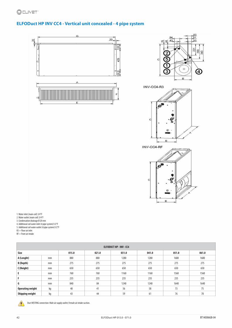
42 ELFODuct HP 015.0 - 071.0 BT14E006GB-04
ELFODuct HP INV CC4 - Vertical unit concealed - 4 pipe system
1. Water inlet (main coil) 3/4”F2. Water outlet (main coil) 3/4”F3. Condensation drainage Ø 20 mm4. Additional coil water inlet (4 pipe system)1/2”F5. Additional coil water outlet (4 pipe system)1/2”FR3 = Floor air inletRF = Front air intake
ELFODUCT HP - INV - CC4
Size 015.0 021.0 031.0 041.0 051.0 061.0
A (Lenght) mm 880 880 1280 1280 1680 1680
B (Depth) mm 275 275 275 275 275 275
C (Height) mm 650 650 650 650 650 650
E mm 760 760 1160 1160 1560 1560
F mm 235 235 235 235 235 235
G mm 840 84 1240 1240 1640 1640
Operating weight kg 40 41 56 58 73 75
Shipping weight kg 43 44 59 61 76 78
Duct NESTING connection: Male air supply outlet; Female air intake suction.

BT14E006GB-04 ELFODuct HP 015.0 - 071.0 43
Page intentionally left blank

w w w . c l i v e t . c o mw w w.cl ivet l ive.com
A Group Company of
CLIVET SPAVia Camp Lonc 25, Z.I. Villapaiera - 32032 Feltre (BL) - Italy Tel. + 39 0439 3131 - Fax + 39 0439 313300 - [email protected]
CLIVET GROUP UK LIMITED 4 Kingdom Close, Segensworth East - Fareham, Hampshire - PO15 5TJ - United KingdomTel. + 44 (0) 1489 572238 - Fax + 44 (0) 1489 573033 - [email protected]
CLIVET GROUP UK Limited (Service Department)Units F5&F6 Railway Triangle Ind Est, Walton Road - Portsmouth, Hampshire - PO6 1TG - United KingdomTel. +44 (0) 2392 381235 - Fax. +44 (0) 2392 381243 - [email protected]
CLIVET ESPAÑA S.A.U.C/ Bac de Roda, 36 - 08019 Barcelona - EspañaTel: +34 93 8606248 - Fax +34 93 8855392 - [email protected]
Av.Manoteras Nº 38, Oficina C303 - 28050 Madrid - EspañaTel. +34 91 6658280 - Fax +34 91 6657806 - [email protected]
CLIVET GmbH (Hydronic and Applied Division)Hummelsbütteler Steindamm 84, 22851 Norderstedt - GermanyTel. + 49 (0) 40 32 59 57-0 - Fax + 49 (0) 40 32 59 57-194 - [email protected]
CLIVET GmbH (VRF, Residential and Lightcom Division)Eisenstrasse 9c, 65428 Rüsselsheim/Frankfurt - GermanyTel. + 49 (0) 6142 83594-0 - Fax + 49 (0) 6142 83594-20 - [email protected]
CLIVET RUSSIA Elektrozavodskaya st. 24, office 509 - 107023, Moscow, RussiaTel. + 74956462009 - Fax + 74956462009 - [email protected]
CLIVET MIDEAST FZCODubai Silicon Oasis (DSO), High Bay Complex, Office N. 20, PO BOX 342009, Dubai, UAE Tel. + 9714 3208499 - Fax + 9714 3208216 - [email protected]
CLIVET AIRCONDITIONING SYSTEMS PRIVATE LIMITED4BA, Gundecha Onclave, Kherani Road - Sakinaka, Andheri (East) - Mumbai 400 072 - IndiaTel. +91 22 6193 7000 - Fax +91 22 6193 7001 - [email protected]