Elements of Mechanical Engineering-Complied
10
ELEMENTS OF MECHANICAL ENGINEERING (MES 14) SESSION 1 CHAPTER 6 SOLDERING, BRAZING & WELDING INTRODUCTION Some products cannot be manufactured as a single piece. The desired shape and size of such products can be ob tained by joining two parts of same or different materials. These parts are manufactured individually and are joined together to obtain the desired product. For example, air craft and ship bodies, welded machine frames, furniture, computers, bridges and the transmission or electric towers etc., are all fabricated by joining several different parts. Based on the type of joint produced joining processes can be classified as 1. Te mpor ary Joint. 2. Pe rmanent J oi nt. If a product is in use for a long time and there is wear and tear, the parts need to be disma ntled for maint enance, repair or repla cement . A tempo rary joint can be easil y disma ntled separating the original parts without any damage to them. In case it is a permanent joint, an attempt to separate the parts already joined will result in the damage of the parts. In a permanent joint, the joint is made such that it has properties similar to the base metal of the two parts. The joined parts become one piece. These parts cannot be separated into their original shape, size and surface finish. Based on the process used for making the joint, the joining processes can be further classified as 1. Sol dering. 2. Brazing. 3. Welding. 4. Mechanical Fas tener s lik e bolts, nuts, rivets, screws etc. 5. Adhesive bonding. Mechanical fasteners are most widely used for temporary joints. Joints obtained by bolts and screws are temporary in nature and can be dismantled easily whenever necessary. Rivets are semi-permanent fastening devices and the joint can be separated only by destroying the rivet without affecting the parent elements. Adhesive bonding has generally less strength than the mechanical fasteners. But adhesive bonding is used to join odd shaped parts or thin sheets which may not lend themselves to mechanical fastening. Brazing and soldering are considered to form pe rma nent joi nts , but for repair or replac eme nt these joints can be dismantle d by hea tin g. Welding is one of the most extensively used fabrication method. The joint strength obtained in welding is being equal to or some times more t han that of the parent metal. Welding is not only used for making structur es, but also for repair work such as the joini ng of broken casti ngs. The choice of a particular joining process depends on several factors such as application, nature of loads or stresses, joint design, materials involved and size and shape of the components. Notes prepared by T.N.Sreedhar and L.Krishnamurthy NIE
-
Upload
coorgtiger -
Category
Documents
-
view
222 -
download
0
Transcript of Elements of Mechanical Engineering-Complied
8/6/2019 Elements of Mechanical Engineering-Complied
http://slidepdf.com/reader/full/elements-of-mechanical-engineering-complied 1/10
ELEMENTS OF MECHANICAL ENGINEERING (MES 14)
SESSION 1
CHAPTER 6
SOLDERING, BRAZING & WELDING
INTRODUCTION
Some products cannot be manufactured as a single piece. The desired shape and size of
such products can be obtained by joining two parts of same or different materials. These parts aremanufactured individually and are joined together to obtain the desired product. For example, air
craft and ship bodies, welded machine frames, furniture, computers, bridges and the transmission
or electric towers etc., are all fabricated by joining several different parts.
Based on the type of joint produced joining processes can be classified as
1. Temporary Joint.2. Permanent Joint.
If a product is in use for a long time and there is wear and tear, the parts need to be
dismantled for maintenance, repair or replacement. A temporary joint can be easily dismantledseparating the original parts without any damage to them. In case it is a permanent joint, an
attempt to separate the parts already joined will result in the damage of the parts. In a permanent
joint, the joint is made such that it has properties similar to the base metal of the two parts. The joined parts become one piece. These parts cannot be separated into their original shape, size and
surface finish. Based on the process used for making the joint, the joining processes can be
further classified as1. Soldering.
2. Brazing.
3. Welding.
4. Mechanical Fasteners like bolts, nuts, rivets, screws etc.5. Adhesive bonding.
Mechanical fasteners are most widely used for temporary joints. Joints obtained by boltsand screws are temporary in nature and can be dismantled easily whenever necessary. Rivets are
semi-permanent fastening devices and the joint can be separated only by destroying the rivet
without affecting the parent elements. Adhesive bonding has generally less strength than the
mechanical fasteners. But adhesive bonding is used to join odd shaped parts or thin sheets whichmay not lend themselves to mechanical fastening. Brazing and soldering are considered to form
permanent joints, but for repair or replacement these joints can be dismantled by heating.
Welding is one of the most extensively used fabrication method. The joint strength obtained inwelding is being equal to or some times more than that of the parent metal. Welding is not only
used for making structures, but also for repair work such as the joining of broken castings. The
choice of a particular joining process depends on several factors such as application, nature of loads or stresses, joint design, materials involved and size and shape of the components.
Notes prepared by T.N.Sreedhar and L.Krishnamurthy NIE

8/6/2019 Elements of Mechanical Engineering-Complied
http://slidepdf.com/reader/full/elements-of-mechanical-engineering-complied 2/10
SOLDERING
Soldering is a method of joining similar or dissimilar metals by the application of heat
and using a filler metal or alloy called solder, whose liquidus temperature is below 450 0 C. The
molten filler metal is made to flow between the two closely placed adjacent surfaces by thecapillary action.
Though soldering obtains a good joint between the two plates, the strength of the joint islimited by the strength of the filler metal used. Soldering is used for obtaining a leak proof joint
or a low resistance electrical joint. The soldered joints are not suitable for high temperature
applications because of the low melting temperatures of the filler metals used.
The purpose of using the flux is to prevent the formation of oxides on the metal surface
when the same is heated. The fluxes are available in the form of powder, paste, liquid or in the
form of core in the solder metal. It is necessary that the flux should remain in the liquid form at
the soldering temperature and be reactive to be of proper use. The filler metals used areessentially alloys of lead and tin. The composition of solder used for different purposes are as
given below
Soft solder - lead 37% tin 63%
Medium solder - lead 50% tin 50%
Plumber’s solder - lead 70% tin 30%Electrician’s solder - lead 58% tin 42%
Soldering is classified into soft soldering and hard soldering.
Soft soldering is used extensively in sheet metal work for joining parts that are not
exposed to the action of high temperatures and are not subjected to excessive loads and forces or
vibrations. Soft soldering is also employed for joining wires and small parts. The solder is mostlycomposed of lead and tin. In soft soldering, Zinc chloride and ammonium chloride are the most
common soldering fluxes used which are quick acting and produce efficient joints. But because
of their corrosive nature the joint should thoroughly cleaned of all the flux residue from the joint.These are to be used only for non-electrical soldering work. Rosin and rosin plus alcohol based
fluxes are least active type and are generally used for electrical soldering work.
Hard soldering employs solder which melts at higher temperatures ( 6000 C to 9000 C) isstronger than used in soft soldering. Hard solder is an alloy of copper and zinc to which silver is
added some times. German silver, used as a hard solder for steel is an alloy of copper, zinc and
nickel.
Sequence of operations:
The following operations are required to be performed sequentially for making soldered joints.
1. Shaping and fitting of metal parts together: The two parts to be joined are shaped to fit
closely so that the space between them is extremely small and filled completely with
Notes prepared by T.N.Sreedhar and L.Krishnamurthy NIE

8/6/2019 Elements of Mechanical Engineering-Complied
http://slidepdf.com/reader/full/elements-of-mechanical-engineering-complied 3/10
solder by capillary action. If a large gap is present, capillary action will not take place and
the joint will not be strong.
2. Cleaning of surfaces: In order to obtain a sound joint, the surfaces to be soldered arecleaned to remove dirt grease or any other foreign material.
3. Application of flux: The flux is applied when the parts are ready for joining.
4. Application of heat and solder: The parts are held in a vice or with special work holdingdevices so that parts do not move while soldering.
The soldering iron or bit may either be heated electrically or by a gas flame. Thesoldering bit is heated sufficiently so that the heat acquired by it is sufficient enough to melt the
solder immediately when the latter is applied to it. A useful form of soldering iron is the
universal type which has a copper bit tapered to form an edge at its end. This facilitates the bit to
be inclined at any desired angle to suit the odd shaped jobs.
After the soldering iron has been heated to the desired heat, its surface is cleaned and
then dipped in a mixture of flux and solder. The solder is then melted into the joint is smoothed
over and finished by the use of the soldering iron. Another practice is to first dip it in a mass of flux followed by the application of solder. This enables the solder to melt and spread over the hot
surface of the bit to form a coating over it. This operation is known as tinning. After this, the bitis again dipped in the flux to remove the oxides from its surface, if any, and then in the solder
again to pick up its required quantity. It is then ready for application to the work. The solders
which have low percentage of tin have a higher melting point. Sometimes it becomes necessary
to heat up the job instead of the bit to get good results. In soldering big jobs, the solder is used inform of wire, sometimes having a core containing flux.
BRAZING
Brazing is a process of making joints where in coalescence is produced by heating to
suitable temperatures above 5000 C and by using a non-ferrous filler metal having a melting point (up to 9000 C) below that of the base metal, the filler metal being distributed between the
closely fitted surfaces of the joint by capillary action. Brazing gives a much stronger joint than
soldering. The principal difference is the use of a harder filler material commercially known asspelter. Filler metals used in this process may be divided into copper base alloys and silver base
alloys. The spelter is usually an alloy of copper, zinc and tin. Both similar and dissimilar metals
can be joined.
The clearance between the two parts to be joined should be critically controlled. If there
is too much of clearance, the capillary forces may not be sufficient to draw the filler metal into
the joint, whereas insufficient clearance may have too small an amount of filler metal to give riseto any effective strength. Another important factor to be considered is the temperature at which
the filler metal enters the joint. While designing a brazed joint, care has to be taken to account
for the differences in the coefficients of thermal expansion of the two pieces to be joined.
The end of the parts which are to be joined must be chemically clean. The flux along with
spelter (filler metal) is applied to remove oxides from the surfaces. Borax is the most widely
used flux. It will dissolve the oxides of most of the common metals. The parts to be joined are
Notes prepared by T.N.Sreedhar and L.Krishnamurthy NIE

8/6/2019 Elements of Mechanical Engineering-Complied
http://slidepdf.com/reader/full/elements-of-mechanical-engineering-complied 4/10
either clamped or held together through some other suitable means and heated. The spelter,
together with the flux melts and flows along the contacting surfaces, unites with them and
solidifies on cooling to form the joint. It is a good practice to prepare the brazing mixture in theform of a paste and than apply it to the surface. This paste is made by mixing the spelter and
borax (flux) is equal proportions and adding proper amount of water to it to form the paste. Other
fluxes used are mixtures of borax, boric acid, fluorides and chlorides.
Brazing is a much widely used joining process in various industries because of its manyadvantages. Dissimilar metals, such as stainless steel to cast iron can be joined by brazing.
Almost all metals can be joined by brazing except aluminium and magnesium which cannot
easily be joined by brazing.
Because of the lower temperatures used there is less distortion in brazed joints. Also, in
many cases the original heat treatment of the plates being joined is not affected by the brazing
heat. The joint can be quickly finished without much skill. Because of the simplicity of the
process it is often an economical joining method with reasonable joint strength. The brazed jointsare reasonably stronger, depending on the strength of the filler metal used.
Silver brazing makes use of a silver based filler metal. Silver brazing is used to give high
strength joints. Though originally used for jewellery applications, silver brazing is now
extensively used in industrial applications. They can be used with a large range of materials, but
because of its high cost it is used in only special applications requiring high strength and hightemperature service.
Applications of Brazing:
Brazing has been used to manufacture a wide variety of products such as Honey comb
sandwich panels for aircraft missiles, motor cycle frames, air plane propellers, Hydraulic fitting,refrigerator evaporators, manufacture of cutting tools etc.,
The use of pressure-vacuum brazing has found wide spread acceptance in the generalapplication of brazing joint in nuclear, aerospace engineering.
Notes prepared by T.N.Sreedhar and L.Krishnamurthy NIE

8/6/2019 Elements of Mechanical Engineering-Complied
http://slidepdf.com/reader/full/elements-of-mechanical-engineering-complied 5/10
ELEMENTS OF MECHANICAL ENGINEERING (MES 14)
SESSION 2
CHAPTER 6
SOLDERING, BRAZING & WELDING
WELDING
Welding is a process of metallurgically joining two pieces of metals by the application of
heat with or without the application of pressure and addition of filler metal. The joint formed is a permanent joint. Modern methods of welding may be classified under two broad headings.
a. Plastic welding process b. Fusion welding process
In plastic welding process the pieces of metal to be joined are heated to a plastic state andthen forced together by external pressure. This procedure is used in forge welding, resistance
welding, spot welding in which pressure is required.
In the fusion welding, the material at the joint is heated to a molten state and allowed tosolidify. This includes gas welding arc welding and Thermit welding.
The surfaces of the metal which are to be joined by any of the welding processes must be
sufficiently clean to permit clean metallic surfaces to come in to contact. In some operations,materials known as fluxes are applied to the parts being welded to dissolve the oxides or to
prevent the formation of oxides. Fluxes are different for different metals. For ferrous materials
borax, sodium carbonate etc, have been found to give excellent results.
Types of Joints:
The welding joints are classified as Butt, Lap, Tee, Corner joints and edge joints. Thechoice of the type of joint is governed by the kind of metal to be welded, its thickness and
technique of welding. Figure 1 shows the different types of joints used in welding.
Notes prepared by T.N.Sreedhar and L.Krishnamurthy NIE

8/6/2019 Elements of Mechanical Engineering-Complied
http://slidepdf.com/reader/full/elements-of-mechanical-engineering-complied 6/10
Figure 1: Different Types of Joints
ARC WELDING
Arc welding is a method of joining metals with heat produced by an electrical arc. In this
process the heat necessary to melt the edges of the metal to be joined is obtained from an electric
are struck between the electrode (filler rod) and the work, producing a temperature of 4000 0C, inthe welding zone. The heat of the arc melts the base metal or edges of the parts fusing them
together. Filler metal, usually added melts and mixes with molten base metal to form the weld
metal. The weld metal cools and solidifies to form the weld. In most cases, the composition of the filler material, known as welding rod, needed to provide extra metal to the weld, is same as
that of the material being welded.
A typical arc welding setup is shown in Figure 2.
1. An arc welding circuit consists of a power supply to furnish electric power.
2. An electrode to conduct the electricity to the arc.3. Cables which connect the power supply to the electrode and workpiece to complete the
welding circuit.
4. The arc itself provides the heat for welding.5. The workpiece to welded is kept on a metallic table.
Figure 2: Arc Welding Setup
Notes prepared by T.N.Sreedhar and L.Krishnamurthy NIE

8/6/2019 Elements of Mechanical Engineering-Complied
http://slidepdf.com/reader/full/elements-of-mechanical-engineering-complied 7/10
The arc must be shielded because; as it hardens the molten metal combines with oxygen
and nitrogen to form impurities that weaken the weld. Shielding can be obtained by adding a
paste, powder or fibrous flux to the arc. The electrodes are usually coated with a flux. Thiscoating forms a gaseous cloud that shields the molten metal from the atmosphere. The coating
also forms a protective slag. The slag floats on the molten pool and hardens as the weld cools.
This keeps impurities out of the weld. The process is shown in Figure 3.
Figure 3: Arc Welding Process
Advantages:
1. As a manual process it is applicable to an infinite variety of work and can be executed inany position.
2. There is less buckling and warping of the work.
3. It produces strong sound and ductile welds.4. Satisfactory welds can be produced in heavy as well as in light sections.
5. Low cost process.6. Excellent joint properties can be obtained in mild, low alloy and stainless steels, nickel
and copper-base alloys.
7. Low accuracy in setting up required.
Disadvantages:
1. Basically a manual process requiring adequate operator skill for good results.
2. Electrodes require frequent changing.
3. Multi run welds necessary on thick plate-slag chipping necessary after each run.4. The principal disadvantage has been the high heat of the metal arc which makes it
unsuitable for use on materials less than 1.55 mm thick.
5. High initial cost of welding equipment.
Arc welding is the most widely used fabrication process at present. This pre-eminence will be
maintained in initial fabrication, repair work and maintenance.
Notes prepared by T.N.Sreedhar and L.Krishnamurthy NIE

8/6/2019 Elements of Mechanical Engineering-Complied
http://slidepdf.com/reader/full/elements-of-mechanical-engineering-complied 8/10
GAS WELDING
Gas welding is a fusion welding process, in which a flame produced by the combustion of gases is employed to melt the metal. The molten metal is allowed to flow together thus forming a
solid continuous joint upon cooling. By burning pure oxygen in combination with other gases, in
special torches, a flame upto 33000
C can be attained. The gas is purchased in cylinder andconnected through resulting valves and pressure gauges into flexible hoses attached to the
nozzle. A typical arrangement is shown in Figure 4.
Figure 4: Gas Welding Equipment
The oxy-acetylene flame is used to pre heat the parts to be welded around the joint andalso to melt the filler metal. A jet of oxy acetylene flame issuing from the nozzle of a burner is
played on the junction of the two pieces to be welded. At the same time a filler rod is held in thezone of jet and its melt is deposited on the fused junction. A weld is obtained after the moltenmetal solidifies. The coating on the filler rod acts as a flux to keep the joint clean.
The filler metal or filler rod used must combine with the parts being joined. The melting point of the filler metal must be the same or lower than the melting point of the metal being
joined.
The correct adjustment of the flame is very important for reliable works. When oxygen
and acetylene are supplied to the torch in nearly equal volumes, a neutral flame is produced
having a maximum temperature of 32000C. This neutral flame is desired for most welding
operations. Neutral flame has little effect on the base metal and sound welds are produced whencompared to other flames. Figure 5 shows neutral flame.
Notes prepared by T.N.Sreedhar and L.Krishnamurthy NIE

8/6/2019 Elements of Mechanical Engineering-Complied
http://slidepdf.com/reader/full/elements-of-mechanical-engineering-complied 9/10
Figure 5: Neutral Flame
In a carbonizing flame or reducing flame excess of acetylene is present. The temperature
of this flame is low. The excess unburnt carbon is absorbed in ferrous metals, making the weld
hard and brittle. In between the outer blue flame and inner white cone, an intermediate flamefeather exists, which is reddish in colour. The length of the flame feather is an indication of the
excess acetylene present. Figure 6 shows a carbonizing flame. Carbonizing flame is used for
welding high carbon steels and cast iron, alloy steel and for hard facing.
Figure 6: Carbonizing Flame
In an oxidizing flame excess of oxygen is present. The flame is similar to the neutral
flame with the exception that the inner white cone is some what small, giving rise to higher tip
temperatures. Excess of oxygen in the oxidizing flame causes the metal to burn or oxidize
quickly. Oxidizing flame is useful for welding some nonferrous alloys such as copper and zinc base alloys. The Figure 7 shows the oxidizing flame.
Figure 7: Oxidizing Flame
Notes prepared by T.N.Sreedhar and L.Krishnamurthy NIE
8/6/2019 Elements of Mechanical Engineering-Complied
http://slidepdf.com/reader/full/elements-of-mechanical-engineering-complied 10/10
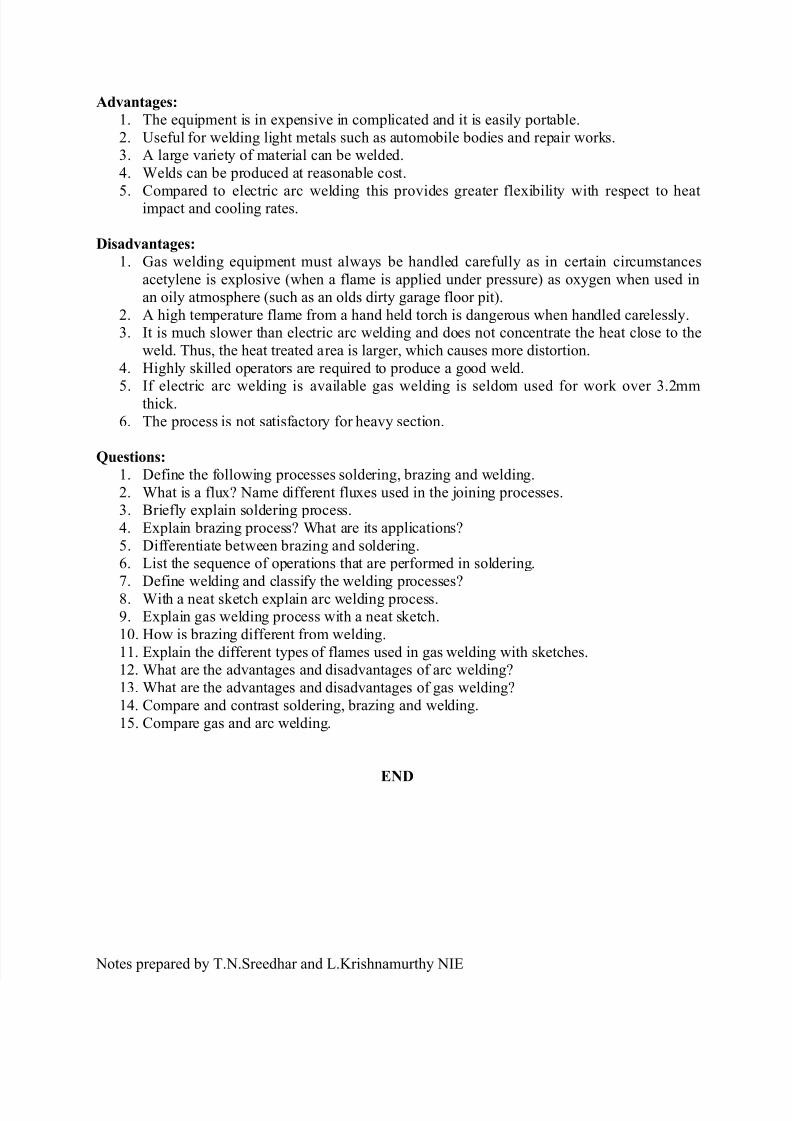
Advantages:
1. The equipment is in expensive in complicated and it is easily portable.
2. Useful for welding light metals such as automobile bodies and repair works.3. A large variety of material can be welded.
4. Welds can be produced at reasonable cost.
5. Compared to electric arc welding this provides greater flexibility with respect to heatimpact and cooling rates.
Disadvantages:
1. Gas welding equipment must always be handled carefully as in certain circumstances
acetylene is explosive (when a flame is applied under pressure) as oxygen when used in
an oily atmosphere (such as an olds dirty garage floor pit).
2. A high temperature flame from a hand held torch is dangerous when handled carelessly.3. It is much slower than electric arc welding and does not concentrate the heat close to the
weld. Thus, the heat treated area is larger, which causes more distortion.
4. Highly skilled operators are required to produce a good weld.
5. If electric arc welding is available gas welding is seldom used for work over 3.2mmthick.
6. The process is not satisfactory for heavy section.
Questions:
1. Define the following processes soldering, brazing and welding.
2. What is a flux? Name different fluxes used in the joining processes.3. Briefly explain soldering process.
4. Explain brazing process? What are its applications?
5. Differentiate between brazing and soldering.6. List the sequence of operations that are performed in soldering.
7. Define welding and classify the welding processes?
8. With a neat sketch explain arc welding process.9. Explain gas welding process with a neat sketch.
10. How is brazing different from welding.
11. Explain the different types of flames used in gas welding with sketches.12. What are the advantages and disadvantages of arc welding?
13. What are the advantages and disadvantages of gas welding?
14. Compare and contrast soldering, brazing and welding.
15. Compare gas and arc welding.
END
Notes prepared by T.N.Sreedhar and L.Krishnamurthy NIE
![ELEMENTS OF MECHANICAL ENGINEERING [15EME14 / 24]alphace.ac.in/downloads/notes/basic science/15EME14_NOTES.pdf · ELEMENTS OF MECHANICAL ENGINEERING ... ELEMENTS OF MECHANICAL ENGINEERING](https://static.fdocuments.net/doc/165x107/5b81ea017f8b9a2b678d762b/elements-of-mechanical-engineering-15eme14-24-science15eme14notespdf.jpg)