elements 36, Issue 3 | 2011 - Evonik Industries · elements36 Issue 3|2011 Collaboration with...
40
elements36 Quarterly Science Newsletter Issue 3|2011 Energy efficiency Ionic liquids: Cooling and heating with heat Resource efficiency High-performance polymers produce biomethane
Transcript of elements 36, Issue 3 | 2011 - Evonik Industries · elements36 Issue 3|2011 Collaboration with...

elements36Quarterly Science Newsletter Issue 3|2011
Energy efficiency
Ionic liquids: Cooling and heating with heatResource efficiency
High-performance polymers produce biomethane

2 Contents
elements36 Issue 3|2011
Cover PiCture
Details well worth a look: Distribution system and cooling loop of an absorption chiller
neWs
4 Dr. Peter Nagler appointed Chief Innovation Officer 4 New monosilane plant in Japan 5 Collaboration with Unilever extended 5 Lupinesse: A new “Ice Cream Age” for people allergic to milk products
resourCe eFFiCienCY
6 High-performance polymers produce biomethane
enerGY eFFiCienCY
12 Ionic liquids: Cooling and heating with heat
neWs
18 Evonik employee awarded prize for outstanding doctoral thesis 18 Thermal insulation with back-foamed PLEXIGLAS® 19 CAMISMA—new composites for lighter cars
CAtALYsis 20 Lindlar catalysts: A lead-free alternative
LiFe CYCLe Assessment 22 A precise view of the whole picture Life cycle thinking: An in-house team of experts evaluates
the entire life cycle of new products and processes
neWs
30 Suitable for patients with allergies: Dental implants made from VESTAKEEP® PEEK
30 New liner technology offers up to 50 percent cost savings 30 New 0W-20 engine reduces fuel consumption and
CO2 emissions 31 Glycine capacity expanded
CoAtinG & BonDinG teCHnoLoGies
32 UV-cured coatings: Greater matting freedom
neWs
39 SEA LIFE Speyer: Rare Cuban crocodile admired behind PLEXIGLAS®
39 Credits
12
22
32

eDitoriAL 3
elements36 Issue 3|2011
New territory
Patrik WohlhauserMember of the Executive Board of Evonik Industries AG
What happens when you put about 15 researchers from various disciplines in a room, ask them to develop a new technology platform, and give them three years to do it? Will they succeed or fail? Evonik first explored this question eleven years ago—with the establishment of the Nanomaterials Project House.
The three-year duration, which was meant to prevent a project from becoming a never-ending story, drew particular criticism. Since then, the critics have become considerably quieter, because what was then a most unusual approach to thinking outside the box has proven to be remarkably successful. We have started nine pro-ject houses so far, and they have spawned a multitude of innovative products and processes. Our joint venture Li-Tec, for example, in which we produce lithium-ion battery cells for electric cars in partnership with Daimler, would not have been possible without the new ceramic membrane that separates anode from cathode. Our former Nanomaterials Project House played a key role in realizing this develop-ment. Other examples include the fermentation technology we use to produce specialty amino acids and—to cite a current field of work at the System Integration Project House, which is still underway—a low-cost process suitable for the mass production of PLEXIGLAS® and Rohacell® lightweight parts for automotive applica-tions.
Because the markets are constantly changing, we have also continually modified our concept. While the first project houses focused on researching basic technology and developing technology platforms, the System Integration Project House thinks in terms of entire systems. It is no longer just about one isolated product but also the associated production process and processing technology.
Our latest project house, Light & Electronics, takes this idea even further by liter-ally entering new territory as the first project house located outside Germany. Light & Electronics is now housed at ITRI (Industrial Technology Research Institute) in the Taiwanese city of Hsinchu. ITRI is Taiwan’s leading research institute and is considered the nucleus of the country’s thriving electronics industry. Here, the pro-ject house will work on displays, photovoltaics, and lighting, form research partner-ships, and give us a new way to access the electronics market.
The conditions are favorable: ITRI, which has conducted its electronics research in close cooperation with the industry since the 1970s, employs 6,000 people. Of these, more than 60 percent have a master’s degree or doctorate. Since its inception, ITRI has accumulated over 10,000 patents, produced 70 managers and executives, and has helped establish 165 companies—figures that provide impressive proof of the innovative power of the Institute.
Over the long term, the new project house in Taiwan, centrally located in one of the world’s most important electronics markets, is slated to give rise to a new R&D competence center. I am optimistic that we will make this a reality as well—and that, once again, our project house will prove to be a successful research concept.

4 neWs
elements36 Issue 3|2011
Dr. Peter Nagler appointed Chief Innovation Officer
On July 1, 2011, Dr. Peter Nagler took up the newly created post of Chief Innovation Officer (CIO). With this, Evonik is sending out a clear signal of its intention to further promote a well-developed innovation culture as a specialty chemicals company. Since April 2009 Dr. Nagler has been head of Corporate Innovation Strategy & Management, to which AQura GmbH, Intellectual Property Management, and, since 2009, Creavis be-long.
In his new post, Nagler will support Evonik’s growth plans, in particular through an adequate innovation strategy for the Group as a whole. This involves disseminat-ing Best Practice experiences from current innovation projects and implementing new methods as well as promoting global activities in the area of R&D with additional centers of excellence in strategically important growth regions. Other important foci of the new CIO’s work are knowledge networking with
internal and external partners, protection of intellectual property, and systematic promo-tion of entrepreneurship and innovation cul-ture.
Dr. Nagler, who holds a doctorate in chemistry, began his professional career in
1986 at the former Degussa AG. In addition to holding several executive and managerial posts at the Hanau-Wolfgang and Frankfurt sites, Nagler was from 1993 onward Cor-porate Development Manager and then Managing Director of Rexim S.A. in Paris (France). On his return to Germany, he head-ed the Fine Chemicals Business Line from 1997 onward and the Advanced Intermediates Business Line from 1999 onward at the then Degussa-Hüls AG in Frankfurt, where he took over as head of the Fine Chemicals Business Unit in 2001 and subsequently of the Exclusive Synthesis & Catalysts Business Unit. From 2005 onward he was South American regional president in Sao Paulo (Brazil). Two years later he transferred once again to Hanau as head of Research & Development, and in early 2008 was appointed head of Innovation Management of the Inorganic Materials Business Unit in Frankfurt before accepting his current position.
New monosilane plant in Japan
In June, Evonik Industries and its partner Taiyo Nippon Sanso Corporation (TNSC) officially started up the new integrated pro-duction facility for monosilane and AEROSIL® in Yokkaichi, 400 kilometers south of Tokyo (Japan). Evonik has thus realized a future-oriented project to serve the growing photo-voltaic and electronic markets. The project volume was around € 150 million and the facility was the company’s largest single pro-ject in 2010. Evonik has a long-term agree-ment to supply monosilane to TNSC. Mono-silane is used in the production of thin film solar cells, flat-screen displays, and semicon-ductors for the electronics industry. Appli-cations for AEROSIL® include process ing into plastics, colorants, and coatings.
At the opening ceremony in Yokkaichi, Klaus Engel, Chairman of Evonik’s Executive Board, commented: “This substantial invest-ment in Japan expands our significant market and technology position in the future-orient-ed solar energy market. It also makes a further important contribution to the global resource efficiency megatrend.” Engel said that he was shocked by the serious natural
catastrophe that hit Japan in March and its consequences for the Fukushima nuclear power station. He stressed: “It is therefore especially important that today we are able to join with our employees, partners, and guests to provide a new signal through the start-up of this facility.”
Thomas Hermann, who heads the Inorganic Materials Business Unit, explained: “The monosilane produced in Yokkaichi will enable us to participate in the high growth in applications for thin-layer photovoltaics, flat-screen displays, and semiconductors, especially in Asia.” Evonik’s partner TNSC
is one of the leading global distributors of industrial and special gases, including silanes, and has supplied key customers in the Asian electronics industry for many years.
The process used to produce monosilane at this new plant was developed by Evonik, which already operates a facility using this technology in Rheinfelden (Germany). The new plant in Yokkaichi will serve the Asian market with electronic-grade monosilane. Evonik is one of the world’s major producers of chlorosilanes and monosilane and there-fore produces key components for the solar energy and electronics industries.
Evonik’s new monosilane plant in
Yokkaichi (Japan)

neWs 5
elements36 Issue 3|2011
Collaboration with Unilever extended
For 25 years now, Lipton—a Unilever sub-sidiary and the world’s premier tea supplier—has been relying on the special expertise of the Advanced Intermediates Business Unit, which is an arm of Evonik Industries, for decaffeinating its black, green, and cold-brew teas. Lipton is the world market leader in decaffeinated teas, which are in partic ularly high demand on the North American market.
The two parties, Lipton and Evonik, will continue their successful collaboration seam-lessly on the basis of a new agreement. “With this agreement, we’ll be expanding the tea
business with Lipton over the next few years,” explained Dr. Manfred Schmidt, product manager at Evonik.
At its Münchsmünster site in Upper Bavaria, Evonik uses a special extraction pro-cess that employs supercritical carbon diox ide at high pressure to remove caffeine and any harmful substances from tea while nearly ful-ly retaining the constituents that give it its flavor and health-promoting properties. Compared to traditional methods, this process is particularly gentle, easy on the en viron-ment, and efficient with resources. The
Münchs münster tea decaffeination plant has received International Food Standard (IFS) certification from the Deutsche Gesellschaft für Qualität (German Society for Quality).
“Evonik has been a tremendously reliable partner of ours for several years and supplies decaffeinated tea of the highest quality,” said Gilbert Kendzior, Tea and Herbals Supply Manager at Lipton. From this base, the two companies plan to extend their collaboration beyond tea decaffeination to other products and applications in the Unilever Group’s food and beverages sector.
Lupinesse: A new “Ice Cream Age” for people allergic to milk products
Those with lactose intolerance or dairy aller-gies can now enjoy ice cream without wor-ry—thanks to Lupinesse, a new development from the Fraunhofer Institute for Process Engineering and Packaging (IVV) in Freising (Germany). The CO2 extraction process of Evonik’s Advanced Intermediates Business Unit plays a key role in its production. Lupinesse is a strictly vegetarian ice cream, contains proteins from the seed of the sweet lupine, and is completely free of lactose, gluten, cholesterol, as well as animal fats and proteins. Since May 2011, ice cream lovers have been able to buy Lupinesse at EDEKA Southern Bavaria (Germany) and EDEKA Southwest (Germany) in the flavors Vanilla Cherry, Strawberry Mousse, Walnut Dream, and Choco Flakes.
In the ice cream, Prolupin GmbH, a spin-off of the Fraunhofer Institute that markets Lupinesse, uses the non-alkaloidal blue lupine (Lupinus angustifolius)—an especially protein-rich legume, native to Germany, that has been grown increasingly in Mecklenburg-Vor pom-mern in recent years. The lupines come from certified cultivation and are free of genetically modified ingredients.
It is the emulsifying and foaming proper-ties of the lupine proteins, which are super ior to those of soy proteins, that are responsible for the creaminess of the ice cream. This is why lupine proteins can completely replace the animal proteins from the milk without sacrificing the creaminess and texture of the ice cream. “But this also means that there must not be any change in their technofunc-tional properties, particularly their emulsify-ing properties, when they are extracted from
the seed,” explains Dr. Ralf Kahleyss, head of research and development CO2 extraction technology of Evonik.
To isolate the proteins as completely as possible and without modification, the fat content of the seed—about seven percent—must be removed as gently as possible. Conventional degreasing agents, such as hexane, are unsuitable because they require relatively high temperatures, which can damage the proteins. “CO2 extraction is the only method gentle enough to remove the fat without destroying the functional protein structure,“ stresses Kahleyss. It is also excep-tionally eco-friendly and resource-efficient. This is why Prolupin relies on Evonik to de-grease the seeds, since the company has more than 25 years’ experience with CO2 extraction at its Münchsmünster site (Germany).
The seeds that have been removed from their pods are husked, conditioned, processed
to flakes, and degreased with CO2 in Münchs-münster. Prolupin then extracts the lupine proteins. Along with other typical ingre-dients, the lupine proteins form the basis of the purely vegetarian lupine ice cream.
Lupine ice cream was developed primarily for people with lactose and gluten intolerance, as well as for those allergic to cow’s milk. In the future, lupine proteins could also aid en-joyment of other products that normally con-tain milk: Prolupin is already considering replacing milk protein with lupine proteins in such products as yogurt, pudding, and quark. Evonik is following these plans with great interest: “Replacing milk protein with lupine proteins is an innovative food concept that offers the consumer genuine added value,” says Dr. Thomas Sauer, head of the Custom Manufacturing Agro market segment. “We see this as an attractive market with great potential for our CO2 extraction process.”
Lupinesse, a new ice cream with lupine proteins, is manufactured in a process developed by Fraunhofer researchers

6 resourCe eFFiCienCY
elements36 Issue 3|2011
New polymer membranes make it easy and efficient to refine biomethane from renewable raw materials
High-performance polymers produce biomethane
Biogas plant. Of all renewable energies, biogas has the advantage that it can be used continuously. It can also be fed into the existing natural gas network after refining
In the future, biogas will play an increasingly larger role as an environmentally sound and domestic source of energy. Specialists from Evonik have developed highly selective polymer membranes for the refining and scrubbing of the gases. The pilot plant that has been in operation in Neukirchen (Austria) since the beginning of the year has proven that the membranes are reliable and cost-effective for convert-ing raw gas into ultrapure biomethane, which can be fed directly into the grid.
[ text Dr. Goetz Baumgarten, Dr. Markus Ungerank, Dr. Christian Schnitzer, Dr. Axel Kobus ]

resourCe eFFiCienCY 7
elements36 Issue 3|2011
BioGAs HoLDs A special place in the ranks of renewable ener-gies. First of all, it is a domestic energy source and an important building block for local supply structures. It can be used day and night to produce electricity and heat, or as a fuel or natural gas substitute, regardless of the presence of wind, water, or sun. Sec ondly, biogas also achieves the highest energy output per unit of area and conversion efficiency. If biogas is used as a fuel, one hectare of arable land can produce enough biogas a year for a car to travel more than 100,000 kilometers. This is a kilometer equivalent that exceeds all other methods of energy production from biomass: The biothanol produced from the same hectare of land per year would be just enough for a car to travel approx-imately 70,000 kilometers. And that translates into lower costs. Compared to the costs of biogas, the costs per kilowatt hour of producing electricity by solar and wind energy are significantly higher.
An additional advantage can be seen in the fact that biogas production generates only minor quantities of substrate and silt, which can also be reused to produce humus. The biomethane obtained from biogas is easy to store and can be delivered to the consumer through the existing natural-gas network. Another extremely important advantage of generating energy from bio-gas plants is low-CO2 energy production from regenerative raw materials.
How does biogas come into existence? Biogas is created by the microbial fermentation of renewable raw materials such as corn, but also of sludge, liquid manure, or agricultural waste. Compared to natural gas, its key advantage is that biogas com-bustion releases only as much carbon dioxide as the fermented biomass had previously removed from the atmosphere.
As a result, the government and gas suppliers alike have high hopes for biomethane. The German federal government’s Inte-grated Energy and Climate Protection Program (IEKP) provides for broadened availability of biogas over the next few years by feeding more of it into the natural-gas grid in Germany. The goal is to generate an annual 60 billion kilowatt hours by the year 2020, and about 100 billion kilowatt hours by 2030, and feed it into the grid. In 2030, 100 billion kilowatt hours will meet roughly 10 percent of the current demand for natural gas in Ger-many. Voluntary obligations by gas suppliers even provide for ten and 20 percent shares for natural-gas substitutes for the years 2010 and 2020.
During fermentation, microorganisms convert the carbo-hydrates, proteins, and fats of plants, liquid manure, or sludge, under anaerobic conditions, into the primary products methane and carbon dioxide. It is also normal for the process to generate traces of hydrogen, nitrogen, oxygen, hydrogen sulfide, and ammonia as well. The composition of the gases depends largely on the substrate and the operating mode of the digester. The methane content is always valuable: The higher the methane content, the higher the energy content of the gas.
Conventionally, biogas is turned into electricity right where it is produced. Only as much as 40 percent of the energy content can be used as electricity, however. And it is extremely rare for the heat generated in the process to be recycled sufficiently. On the other hand, if the gas is fed into the grid, more than 90 per-cent of the energy content can be used.
Separation of CO2 is key for biogas refiningBefore biogas can be fed into the grid, it has to be thoroughly cleaned, dried, and refined. Hydrogen sulfide and ammonia, for example, must be removed to prevent corrosion in engines and downstream components such as heat exchangers. Also, water vapor in the biogas can condense and lead to corrosion. This is why the raw gas is dried. In addition, biogas must be pre-
Figure 1
Biogas is produced in a biogas plant through microbial fermen-tation of renewable raw materials such as corn, but also of sludge, liquid manure, or agricultural waste in a biogas plant. After separating the CO2 and removing various minor ele-ments such as water vapor and hydrogen sulfide, the biogas can then be used—in the gas network, in combined heat and power stations, and at filling stations
333

8 resourCe eFFiCienCY
elements36 Issue 3|2011
cisely tailored to match the dryness, pressure, and caloric value of the natural gas in the grid.
The most important step in refining is the separation of the carbon dioxide. CO2 is not combustible and, therefore, reduces the heat value. According to the standards defined by the Ger-man Technical and Scientific Association for Gas and Water (DVGW), the CO2 content normally has to be reduced by 25 to 45 volume percent (vol%) to below 6 vol%. Depending on the requirements of the grid operator, the remaining content some-times has to remain below 2 % so that the feed-in of biomethane does not reduce the quality of the natural gas/biomethane mix-ture to values lower than those guaranteed by the grid operator.
Conventional refining plants unsuitable for a future local energy supply systemA variety of processes for separating CO2 have become estab-lished on the market in recent years. The majority of refining plants use the pressure-swing adsorption process, which adsorbs the CO2 and any trace gases through porous materials. Another established method is pressure water washing, in which the CO2, hydrogen sulfide, and ammonia are dissolved and washed out.
Many larger plants rely on the amine washing method, which uses a scrubbing liquid of amine compounds to wash the CO2 out of the biogas stream. A relatively new technology for bio-gas refining, cryogenic gas separation, freezes the carbon di-oxide out of the gas stream at low temperatures.
All these processes have several major drawbacks: They require energy, processing aids, and auxiliary chemicals. They create waste and wastewater, which require treatment and disposal. In addition, the pressure of the biogas is usually low following the latter’s refining, and an additional compressor must be used to compress the gas to pressures of 15 to 20 bar to prepare it for feeding into a medium-pressure grid, for example.
This is why most conventional refining plants are only ef-ficient at raw gas quantities of over 500 standard cubic meters per hour (Nm³/h), and are therefore unsuitable for a future local energy supply system based on numerous small plants.
Higher efficiency with membrane technologyMembrane technology—a field in which high performance plastics producer Evonik has already amassed years of
333
Figure 2
Overview of the various refining processes (modeled after: G. Dachs, C. Zach, Biogasaufbereitungssys-teme zur Einspeisung in das Erdgas-netz—ein Praxisvergleich, SEV Bayern, (2008))
Process Separating effect Through Separation of
Pressure-swing adsorption Adsorption Activated carbon (molecular sieve) CO2 H2S H2O
Pressure water washing Physical adsorption Water CO2 H2S NH3
Genosorb® Physical adsorption Genosorb® CO2 H2S NH3 H2O
Monoethanolamine washing Chemical adsorption Monoethanolamine CO2 H2S
Membrane process Permeation Membrane CO2 H2S NH3 H2O
Cryogenic gas separation Rectification Low temperatures CO2 H2S
Figure 3
Average permeation speeds of various gases in a polyimide membrane
Fast Slow
Figure 4
Gas separation with membranes
Figure 5
How a membrane module for gas separation works
Biogas
CH4 CO4 NH3 H2S H2O
Membrane
Methane enriched Retentate
CO2 enriched Permeate
Permeate
Hollow fiber membranes
Feed Retentate

resourCe eFFiCienCY 9
elements36 Issue 3|2011
experience—promises far more flexibility, and energy and cost effi ciency. Gas separation with polymer membranes exploits the fact that gas molecules vary in size and solubility in the poly mer.
This also applies to the refining of biogas: Because CO2 mol ecules are smaller than methane molecules and also dissolve better in polymers, they can pass through the micropores of the membrane far more quickly. Consequently, the methane collects on the high-pressure side of the membrane, while water vapor, ammonia, hydrogen sulfide, and most of the CO2 pass through the molecular sieve. Because the methane-rich gas is removed on the high-pressure side, it also requires no further condens-ing.
Rugged and selective: Membranes made from polyimidePolyimides are high-performance plastics that are extremely pressure and temperature resistant. They have long been used successfully for filter bags in the cement industry, for example, where they separate the dust from the hot waste gas.
In recent years, Evonik has developed membranes based on these kinds of polyimides. They display a consistently high
sel ectivity, and are particularly suited to separating CO2 and methane: Unlike other polymers, the polyimides used do not interact with carbon dioxide, which plasticizes certain plastic membranes with prolonged exposure, thereby significantly reducing their selectivity.
Polyimides are produced by polymerization of carboxylic dianhydride and diamines. Through a process called “phase in-version,” the polymer is spun into fine fibers. A solvent ensures that the fibers are hollowed out as they go through the spinne-ret. Following drying and aftertreatment, the fibers are thin and hollow, with an outside diameter of a few 100 micrometers and a membrane wall less than 100 micrometers thick. Several thousand of these hollow fibers are bundled, the ends embedded in a resin, and the bundle inserted into a metal pipe. The finished module can now be subjected to a pressurized gas mixture.
Past experience shows that polyimide membranes for gas sep aration are a rugged and simple tool for scrubbing gas. Used for refining biogas, they feature high plant availability, low energy consumption, and low maintenance costs compared to alternative processes.
But the disadvantage of the polyimide membranes currently available on the market is that appreciable amounts of 333
Hollow fiber bundle and membrane modules (left) from Evonik

10 resourCe eFFiCienCY
elements36 Issue 3|2011
methane are lost through “slippage” because their selectivity is too low. This is why effective separation of CO2 and methane must be bought either with energy-consuming, high feedback streams or with a series connection of several membranes in a row—and both increase investment and operating costs. Or the process requires thermal recycling of the methane-rich waste gas, which also normally generates high added costs. As a result of the weak nesses of past membranes, this technology has been unable to compete with other separation methods.
New Evonik polyimide features optimal separation efficiency In the past few years, membrane specialists at Evonik have suc-ceeded in developing exceptionally selective polyimide mem-branes. The polymer chemists rely on a specially optimized form of the company’s time-tested P84® polyimide to produce the new polyimide membranes. In only one step, these new membranes have enabled a significant improvement in the separation of car-bon dioxide and methane. Even at CO2 partial pressures of up to
25 bar—as they occur in biogas refining—the membranes display stable selectivity and thus distinguish themselves from the mem-branes currently available on the market.
Together with Creavis, the strategic research and develop-ment unit of Evonik, as well as the Process Technology & Engi-n eering Service Unit, a process was developed that tapped the full potential of the separation properties of the polyimide mem-branes. Recently, the modules have been produced in two dif-ferent diameters and two different lengths.
Currently, Evonik experts are testing the production mod-ules in a pilot plant in Neukirchen an der Vöckla in Austria. The raw gas is sourced from a farmer’s fermentation plant, which generates biogas from renewable raw materials. Last fall, a con-tainer that houses the entire technology for biogas cleaning and enrichment was installed right next to the fermentation plant. The developers at Evonik monitor and control the process re mot e ly via data line.
The refining capacity of the pilot plant is 10 Nm³/h. The raw gas arrives from the fermentation plant as a mixture of CO2, methane, and the typical secondary components, and is first
333
Figure 7
The initial results of the gas qualities produced with the Evonik membranes: The methane from the raw gas can be cleaned to over 99 percent
CH4 Product gas
CH4 in the raw gas
CO2 in the raw gas
CH4 Off-gas
Figure 6
Evonik’s multi-stage process for refining biogas
Since early 2011, Evonik has operated a pilot plant for biogas refining in Neukirchen an der Vöckla in Austria
Time [h]
0 100 200 300 400 500 600 700 800 900 1,000 1,100 1,200
0
100
90
80
70
60
50
40
30
20
10
Gas content [%]
Raw biogas from fermentation: approx. 53% CH4, 47% CO2
Compressor 10 to 25 bar
Back flow
Product flow biomethane:(> 97% methane) 10 to 25 barEvonik’s
multi-stage membrane
process
Lean gas flow, predominately CO2:< 1% methane

resourCe eFFiCienCY 11
elements36 Issue 3|2011
desulfurized with activated coal, filtered, and pre-dried. This ensures that no condensate forms on the membrane and that no particles or sulfur compounds can deposit on the membrane. The pre-scrubbed gas is then drawn into an oil-free compressor and compressed to about 16 bar.
The skilled interconnection of the individual modules is cru-cial to the success of the process. In each case, the configuration of the modules depends on their number and the requirements for the purity of the methane. In the pilot plant in Neukirchen, part of the gas stream from the unpressurized permeate side is recycled to the first module.
Success promising field testThe technology has worked without disruption since the pilot plant was commissioned in the first quarter of 2011. In Neu-kirchen, Evonik experts are studying key parameters, such as the capacities of various modules, their longevity, stability, and selectivity. They vary the pressure and material flows to devel op the optimal process conditions. So far, the results have been highly promising: The methane from the raw gas can be cleaned to over 99 percent, with less than 0.5 percent methane present in the waste gas.
This means that nearly all the methane from the fermenta-tion is produced to biomethane quality. Additionally, following the membrane-based refining process, the biomethane is already dry and meets the dewpoint requirement for it to be fed into the grid. Because the methane slip is below 0.5 percent, no addition al incineration of the lean gas is necessary. The refining is energy efficient, it generates neither waste nor emissions, and requires no processing aids such as water or sorbents. All these translate directly into lower costs. Compared to gas wash ing or adsorp-tion processes, biogas refining with the new membrane modules is significantly more cost-effective, particularly when it comes to typical biogas plant sizes.
An additional advantage can be seen in the fact that the pro-cess is highly flexible. It can be used in both small and large plants, and can be easily adapted to changing volume flow rates and gas compositions. The plants can also be started and stopped at short intervals, and are therefore ideal for operation of an on-site biomethane filling station. But the innovative membranes can do even more: They not only scrub biogas quickly and effi-ciently; they obtain nitrogen from the air just as effectively. They enrich oxygen. They separate hydrogen from synthesis gas, or dry gases and air.
Finally, the current results can be summarized as follows: Compared to other processes, membrane-based gas sep aration is the most promising technology for refining valuable biogas. The technology based on membranes made of P84® polyimide fibers can therefore play a central and leading role in a domestic, local, and climate-friendly energy supply.
Dr. Christian schnitzer is the project manager responsible for membrane activities in the Science- to-Business Center Eco². After studying mechanical engineering and process technology at the Technical University of Kaiserslautern and earning his doctorate in the field of microfiltration with superfine multifila-ment fabrics, he began his career at Evonik in the Process Technology & Engineering Service Unit in 2008. He moved to Creavis in 2009.+49 2365 49-5527, [email protected]
Dr. Goetz Baumgarten is in charge of Business Development Membranes in the Performance Poly-mers Business Unit. After studying chemistry at the University of Hannover and earning his doctorate on the treatment of landfill leachate with membrane processes, he began his career at Amafilter Deutsch-land GmbH in Düsseldorf in 1997. From 2001, he was product manager for the Membrane Technology Product Line for the entire Amafilter Group before moving to Evonik in 2005. At Evonik, he initially head-ed the Membrane Technology Group in the Pro cess Technology & Engineering Service Unit before assum-ing his current position in July 2010.+49 2365 49-4986, [email protected]
Dr. markus ungerank, an employee of Evonik’s subsidiary Evonik Fibres GmbH in Lenzing (Austria), is responsible for R&D for the Fibers and Membranes Growth Line of the High Performance Polymers Busi-ness Line. After studying chemistry at the Technical University of Graz and earning his doctorate on the subject of liquid crystalline polymers, Ungerank began his career at Evonik Fibres GmbH as project head for development of the P84® polyimide powder. Two years later, he became director of the R&D unit and super-vised the market launch of the new P84® polyimide powder. In 2007, he worked with Dr. Goetz Baum-garten to initiate the development of innovative mem-branes for gas separation based on P84® polyimide. +43 7672 701-2508, [email protected]
Dr. Axel Kobus works in the High Performance Poly mers Business Line. Since July 2010, he has been respons ible for the Fibers and Membranes Growth Line, which focuses on using high-performance poly-mers for energy and material efficient sepa r ation tech-nologies for the processing industry. After studying process technology and earning his doctorate in the field of absorption and thermal separation technology, he began his career at Evonik in 1999 as a process engineer and head of the pilot plant for fluid process technology. He then worked for a time in Elyria (Ohio, USA) where he was responsible for supply chain management and strategic procurement for the Initia-tors unit, before moving to Hanau in 2005 to head Fluid Process Technology at the Process Technology & Engineering Service Unit. +49 2365 49-5646, [email protected]

12 enerGY eFFiCienCY
elements36 Issue 3|2011
333
The Reichstag in Berlin not only sets the stage for national politics but is a model of “green” construc-tion. Special glazing and insulation reduces heat losses. A photovoltaic system and two cogeneration heat and power plants, operated with biodiesel, can cover over three-quarters of the power requirements. And geothermal energy from below ground provides propulsion for heat and cold accumulators. In the summer months, absorption chillers use part of the heat generated by the two cogeneration plants to cool the rooms in the Reichstag.
A roughly twenty-minute walk from here, absorp-tion chillers like these are also serving the business and office complex on the Potsdamer Platz. Their strength: They use thermal instead of electrical energy to drive the refrigerator cycle—a big plus when it comes to sustainability. Worldwide, an increasing number of office buildings, hospitals, and entire city
Ionic liquids
Cooling and heating with heat
complexes (district cooling) use absorption chillers to generate sustainable air-conditioning—or heat. They are used in airports, and even the Vatican.
The thermodynamics of the working pair is crucialAn absorption chiller contains two dissolved sub-stances in a closed circle—the refrigerant and the absorbent. They represent the so-called working pair. The process is driven by heat and it exploits the fact that the physical solubility of two substances is tem-perature-dependent. But this requirement alone is not enough to make two substances attractive for use in absorption chillers. The absorbent needs to have a high capacity for the refrigerant and the absorbent viscosity must also be low enough to ensure an ef fi - c ient heat and mass transfer.
Absorption chillers use thermal heat instead of electrical energy to air-condition rooms or supply industrial refrigeration. For this reason they can use solar heat to provide cold air, for example. But the potential of absorption chillers and heat pumps has gone largely untapped. This could change in the future, thanks to a new working pair based on ionic liquids developed by Evonik Industries.
[ text Dr. Matthias Seiler, Marc-Christoph Schneider ]

enerGY eFFiCienCY 13
elements36 Issue 3|2011
The Reichstag in Berlin. Here, absorption chillers provide a sustainable source of comfortable temperatures in summer by utilizing the heat from cogeneration heat and power stations
Airconditioned with absorption chillers: Changi Airport in Singapore

14 enerGY eFFiCienCY
elements36 Issue 3|2011
An absorption chiller circle contains four com-ponents: generator, condenser, evaporator, and absorber. In the generator, heat is supplied. While the volatile refrigerant evaporates, a concentrated absor-bent solution is sent back to the absorber. The evap-orated refrigerant then enters the condenser, where it returns to the liquid state. The absorption chiller uses a throttle located behind the condenser to reduce the system pressure to the pressure level of the evaporator and absorber with the corresponding low operating temperatures. This way, the refriger-ant can easily evaporate when a particular amount of heat is taken in. The absorption chiller draws this heat from the surrounding area. The evaporated re frig-erant now flows back into the absorber, where it is captured by the absorbent. Subsequently, both com-ponents—the working pair—are pumped to the gener-ator—and the circle closes.
Cooling and heating with one aggregateThe thermodynamic circle can also be used as an ab-sorption heat pump, because it removes heat from its environment at a low temperature in the evaporator and releases heat at a higher temperature level in the condenser. In principle, both functions—refrigeration machine and heat pump—can be realized in one aggre-gate.
From a technical standpoint, these absorption sys-tems compete with compression-type heat pumps and
cooling machines. A compression heat pump, for example, uses heat at a low temperature to vaporize a refrigerant with a low boiling point. It then uses an electrically-driven compressor to mechanically com-press the gaseous refrigerant, which heats the refrig-erant. At high pressure, it releases its heat to an en-vironmental medium such as heating water or air flow. The refrigerant then cools and re-condenses.
Today, there are many examples of applications in which multi-effect absorption chillers operated with waste heat achieve a comparable or even better performance in terms of carbon footprint and effi-ciency than compression chillers. Absorption chillers have already established a strong market position in Asia. Experts believe that, in the future, the technol-ogy will become increasingly important to other regions of the world thanks to advancements in the development of working pairs, as well as the mega-trends of resource efficiency and sustainability.
Waste heat, solar, or geothermal power as energy sourceAbsorption systems avoid the disadvantages of an electrically driven, unsustainable compressor: They can be operated directly with thermal energy that comes from either a regenerative energy source—such as geothermal or solar power—or from the waste heat e. g. of industrial processes. The International Energy Agency estimates that in Europe alone, sev-eral million gigawatts of low-caloric—and there-
333
333
Energy network of the parliamentary buildings in Berlin with combined power, heat, and cooling technology and aquifer storage. Aquifers are permeable bodies of rock that can hold ground water (diagram source: Die Woche, July 10, 1998)
ElectricityHeating
Hot water
Cooling
Biodiesel produces electricity
Block-type thermal power station Return flow
Thermal heat direct
Hot water/heat that drives the water pump
Surplus heat
Depth: 50 meters
Depth: 300 meters
45 °C 65 °C
90 °C
110 °C
65 °C
6 °C
5 °C
6 °C
Dry cooler
Cold air
Absorption heat pump
cools using heat
Aquifer cold accumulatorIntermediate storage section
for cold water for cooling in summer
Aquifer heat accumulatorIntermediate storage section for hot water accumulated during summer
time operations for use in winter
65 °C67 °C

enerGY eFFiCienCY 15
elements36 Issue 3|2011
Erding, Germany-based INVEN Absorption GmbH designs and builds absorption chillers, absorption heat pumps and heat transformers, as well as sys-tems for industrial refrigeration and heat recovery. CEO Dr. Jürgen Scharfe on the potential of absorp-tion chillers.
What do customers who buy the absorption chillers you design ask for most often?More and more customers are asking for opportuni-ties to use cold with heat from electricity produc-tion—that is, gas or diesel engines. There is more unexploited potential here than ever before. Unfortunately, we can’t offer adequate solutions in every case, because conventional working pairs are of limited use in hotter countries.
What do customers see as the biggest problem with today’s absorption chillers?The biggest problem with the working pairs in cur-rent use is that crystallization of the lithium bromide narrows their functional range. Plants with the con-ventional water/lithium bromide pair require cooling water at temperatures up to about 32°C, which can only be obtained with evaporation coolers. In warmer countries, where water is frequently scarce and some-times extremely valuable, the use of wet cooling towers can be simply unfeasible.
What properties would the ideal working pair have to have?It would have to have the same coefficient of perfor-mance—in other words, the same ratio of cold flow (benefit) to driving heat flow (effort)—as the work-ing pair water/lithium bromide allows but without the crystallization and corrosion problems. In this regard, the performance of the new Evonik system solutions is heading in a very promising direction.
Which customer groups would find absorption chillers with new working pairs particularly appealing?All customers who need refrigeration and who also have access to heat from electricity production. That ranges from airport and hotel operators to city planners and industrial sites. For many customers who are really interested in energy-efficient, sus-tainable refrigeration concepts, absorption cooling is just about the only option over the short and inter-mediate term. Also, let’s not forget the use of solar energy for solar cooling.
sHort intervieW
A working pair that keeps the pipes in the absorber optimally wetted is essential for an efficient heat and mass transport
Flow chart of a single-effect absorption chiller. The four most important components are the evaporator, where the cold is provided, the generator, which receives the driving heat, the absorber, and the condenser
Refrigerant circle Working pair circle Effort (driving heat flow)
Benefit (generated cooling capacity)
Condenser
Evaporator
Generator
Absorber

16 enerGY eFFiCienCY
elements36 Issue 3|2011
fore difficult-to-use—industrial waste heat es-capes into the environment each year. An absorption system is an energy-efficient way to convert part of this waste heat back into useful process heat or cold. An other advantage of absorption systems over com-pression systems is that they do not need problematic refrigerants such as fluorinated hydrocarbons damag-ing the ozone layer.
Classical working pairs have crystalliza-tion, corrosion, or toxicity problemsIn most cases, absorption chillers use water as the refrigerant and lithium bromide as the absorbent. Water/lithium bromide is considered an efficient working pair for absorption systems. But water vapor has a large specific volume and can work only within a relatively narrow range of temperatures. This is why use of water/lithium bromide is limited to air-con di-tioning or supplying cold at temperatures above 0°C.
The water/lithium bromide working pair has other disadvantages, however. Crystallization of the lithium bromide is a big problem. At a concentration of about 65 percent in aqueous solutions, lithium bromide begins to crystallize at 25°C—a particular problem in hot, humid countries. For this reason, ex-pensive cool ing systems are sometimes required to prevent crystallization of the lithium bromide.
Lithium bromide is also highly corrosive at higher driving temperatures. This means that lithium bro-mide can be used to operate the exceptionally energy-efficient, multi-stage absorption cooling processes only when larger quantities of corrosion inhibitors or costly corrosion-resistant materials are used.
Ionic liquids—eco-friendly, non-corrosive, and non-crystallizingEmployees of Evonik’s Advanced Intermediates Busi-ness Unit recognized this problem with the classical water/lithium bromide working pair some time ago. In close cooperation with the company’s Process Technology & Engineering Service Unit, they have de veloped a new system solution that can be used as a working pair in absorption chillers and heat pumps.
Ionic liquids are salts—in other words, made up entirely of ions—that have a melting point below 100°C. Below their degradation temperature, ionic liquids display no measurable vapor pressure. They are extremely stable thermally and electrochemically, and dissolve in a variety of organic, inorganic, and organometallic compounds. Normally, ionic liquids are made up of organic cations and organic or inor-ganic anions. Their physical properties can be fine-tuned by selectively varying the anion/cation com-bination and the ion structure. And compared to conventional salts such as lithium bromide, they are generally far less corrosive.
Because of its expertise in commercial large-scale production of ionic liquids and suitable additives,
One of the strengths of the new IL-based working pair is that they can be used in a much broader range of temperatures and pressures than the state-of-the-art systems
Operating conditions of a LiBr-based working pair Water (100 percent by weight)
Ionic liquids of Evonik/water 56 58 80 88 percent by weight ionic liquid
LiBr/water 50 60 percent by weight Crystallization boundary LiBr (60–70 percent by weight LiBr)
Pressure [mbar]
70 11010 30 50 90
70
10
0
Temperature [°C]
6
Customizing absorbents without crystallization boundaries in the temperature range of minus 100°C to +200°C
Sodium chloride (table salt) Lithium bromide 1-Methyl-3-methylimidazolium chloride 1-Buthyl-3-methylimidazolium chloride Working fluid from Evonik (not chloride-based)
Melting point [°C]
1,000
800
600
400
200
0
–200
333

enerGY eFFiCienCY 17
elements36 Issue 3|2011
Evonik’s team was able to develop a new working pair with significant advantages over the state of the art. This required precise knowledge of the needs and systems of the customer. Based on this knowledge, the team succeeded in developing competitive, sus-tainable system solutions that are custom-tailored from new absorbents and performance additives. The new system solutions meet the extensive require-ments of the chiller or heat pump manufacturers.
These Evonik working pairs score high points in another area, as well: They are significantly less cor-rosive than an aqueous lithium bromide solution and have a far broader operating range. The latter is mainly due to the extremely low melting temperature of Evonik’s ionic liquids ensuring that no crystalliza-tion boundaries occur in the operating range of ab-sorption chillers or heat pumps.
Early integration of customers who know the exact requirements of the market was an enormous benefit to this innovation. Evonik plans to launch its new working pair formulations for absorption chil-lers and heat pumps in 2012.
Highly promising field trialsField trials, such as air-conditioning tests in the mega-watt range, are currently underway with various in-dustry partners. Evonik’s partners in industry are looking to open up completely different applications for the company’s new working pair formulations.
So far, all pilot tests and industrial field trials have shown that absorption chillers and absorption heat pumps always display at least the same favorable coefficient of performance after the working pair is changed from water/lithium bromide to Evonik’s sys-tem solution. When it comes to crystallization and corrosion, however, the ionic liquid is far superior.
Thanks to Evonik’s new working pair formula-tions, the operating parameters of an absorption sys-tem can be designed far more flexibly, which has a favorable impact on costs. For example, Evonik has made it possible to use higher driving temperatures more efficiently in multi-stage plants using air-cooled cooling towers. The potential of absorption systems, therefore, could soon be exploited far more vigor-ously than ever before—for the benefit of sustainable and efficient energy use. 777
Dr. matthias seiler is director for New Business Development in Evonik’s Advanced Intermediates Business Unit. After studying process and energy en-gineering at the TU Berlin and earning his doctorate in the field of polymer process engineering and ther-mo dynamics at the University of Erlangen-Nurem berg, he began his career in Evonik’s Process Technol ogy & Engineering Service Unit in 2004. Here, he at last headed the Bringing Technology to Market Depart ment before moving to his current position in 2010. Parallel to his professional activity, he also earned an Executive MBA at the ESSEC & Mannheim Business School.+49 6181 59-3049, [email protected]
marc-Christoph schneider is a new business devel-opment manager focusing on absorption chillers and heat pumps in the Advanced Intermediates Business Unit. After studying mathematics and chemistry at the Technical University of Darmstadt, he began working in the Business Development Molding Compounds unit of Evonik Röhm GmbH in 2008, while simulta ne-ously studying management engineering with an em-phasis on chemistry at Fresenius University. He moved to the Bringing Technology to Market Depart ment of the Process Technology & Engineering Service Unit in 2009, and began working in his current position in 2011.+49 6181 [email protected]
The Advanced Intermediates Business Unit and the Fluid Processing Department developed and tested the new ILbased working pairs in absorption chillers at the Hanau site. The working pairs are currently undergoing field trials in commercialscale plants to test their endurance over several months. One thing is certain: Evonik can supply the right working pair for every machine produced by the various manufacturers, and it can be filled in the machines “as is,” without the need for technical changes (dropin solution). That is the key to a successful market launch

18 neWs
elements36 Issue 3|2011
Thermal insulation with back-foamed PLEXIGLAS®
How can old buildings in need of renovation be efficiently insulated? Evonik’s Science-to-Business (S2B) Center Eco² is working on an answer to this question. The S2B Eco² falls under the management of Creavis Tech nol-ogies & Innovation, a strategic research unit. In the development line “Solutions for Im-proving Efficiency at the Customer’s,” the S2B Eco² researchers are developing facade elements used in structural renovation. The elements are supposed to contribute to saving energy and reducing CO2 emissions.
Reducing the energy consumed for heat-ing buildings offers a major potential for saving energy and reducing CO2 output. Buildings account for some 40 percent of energy consumed in Germany and for ap-prox imately 30 percent of climate-damaging CO2 emissions. The Federal Government plans continuous revisions of the Energy Saving Ordinance (EnEV) to reach its goal of reduc ing greenhouse gas emissions by 40 percent by the year 2020.
The ordinance currently applies in its version of 2009, but another update, with tighter regulations—with projected cuts by 30 percent—is expected for 2012. In accor-dance with the energy concept recently rati-fied by the federal government, energy-con-scious renovation of buildings is a key to reaching national climate protection goals. Plans call for German buildings to be almost completely CO2-neutral by the year 2050.
Accordingly, the restoration rate of buildings is to be doubled from currently less than 1 percent to 2 percent of the entire structural inventory. This results in continuous demand increases for structural heat insulation.
So-called post-war structures in Germany account for some three-quarters of older structures and thus have the largest potential for energy and CO2 savings in buildings. Much heat is lost through leaky windows and roofs and poorly insulated walls. Since such buildings are not in compliance with the cur-rent EnEV ordinance, retrofitting is manda-tory.
Renovation in accordance with EnEV 2012, however, would mean that today’s insulation panels, which are about 14 cm thick and are made from conventional insulating materials such as Styrofoam or rock wool, would no longer be sufficient. Instead, the new ordi-nance would call for insulation layers of ap-proximately 20 cm. Critical facade compo-nents, such as windows and window reveals or border spacing, create installation difficul-ties and present cosmetic problems. Although appealing architectural solutions are easy to implement in new structures, they cause ad-ditional expenditures in exist ing structures. All this leads to a demand for innovative in-sulation materials with improved properties and comparatively thin formats.
Evonik plans to serve this significant mar-ket with innovative products for a building en velope that will satisfy the requirement of the future EnEV. One of these products is the so-called PMMA Rigid Foam Board, a pre fabricated, polyurethane foam-backed PMMA facade panel made of PLEXIGLAS® Mineral. Since polyurethane has better in-sulating properties than Styrofoam or rock wool, it offers excellent heat protection at comparatively low thicknesses. The mater-ial saves about 30 percent in material thick-ness.
The cover layer of the PMMA facade panel not only provides weather and UV protection, but also resists mechanical stresses.
Slim heat insulation: The PMMA Rigid Foam Board, a prefabricated, polyurethane foambacked PMMA facade panel made of PLEXIGLAS® Mineral, saves about 30 percent in material thickness compared to conven tional bonded heat insulation systems
Evonik employee awarded prize for outstanding doctoral thesis On July 1, 2011, Dr. Stephan Peitz received the GFUR’s Joachim Jungius Prize for his doctoral thesis (summa cum laude). Peitz worked on his doctorate at LIKAT e.V., the Leibniz Institute for Catalysis of Rostock University, in the group of Prof. Uwe Rosen-thal; the subject of his thesis was the selec-tive tri- and tetramerization of ethylene to give unbranched α-olefins. The Joachim Jungius Prize is awarded by GFUR for work done at Rostock University that, in the words of the regulations governing the award, “is distinguished from other theses by its excel-lence and originality and provides fresh im-petus for technology.”
“We share Mr. Peitz’s pleasure at this award,” said Dr. Markus Winterberg, who is responsible for C4 chemistry research in the
Performance Intermediates Business Line. “It confirms once again that in Mr. Peitz we have gained an outstanding scientist.” Since No vem ber 2010 Peitz has been working in Evonik’s Performance Intermediates Business Line on C4 research projects.
Unbranched α-olefins are valuable build-ing blocks for industrial production of, for example, specialty polyethylene, cleaning agents, and synthetic lube oils. When pro-duced by oligomerization of ethylene, how-ever, the product is usually a mixture of olefins that can be separated only with great difficulty. With his doctoral work on homo-geneously catalyzed selective tri- and tetra-merization of ethylene, Dr. Peitz has made a major contribution toward clarifying the reaction mechanism. This is the basic pre-
requisite for the identification of suitable catalysts and development of a selective in-dustrial process with high yield. Com mer-cialization of Peitz’s work is planned.
GFUR e.V. was founded on the initiative of the then Rector, Prof. Gerhard Maess, by members of the university and representa-tives of industry on January 17, 1991. The 250 members include graduates and friends of the Rostock University, political figures, and represen tatives from the worlds of business, technol ogy, and culture. To encourage young scientists, it awards the Joachim Jungius Prize annually for outstanding theses. Joachim Jungius (1587–1657) was a German mathema-tician, physicist, and philosopher, regarded as a pioneer of a new approach to scientific think ing and methodology in Germany.
neWs 19
elements36 Issue 3|2011
CAMISMA—new composites for lighter cars
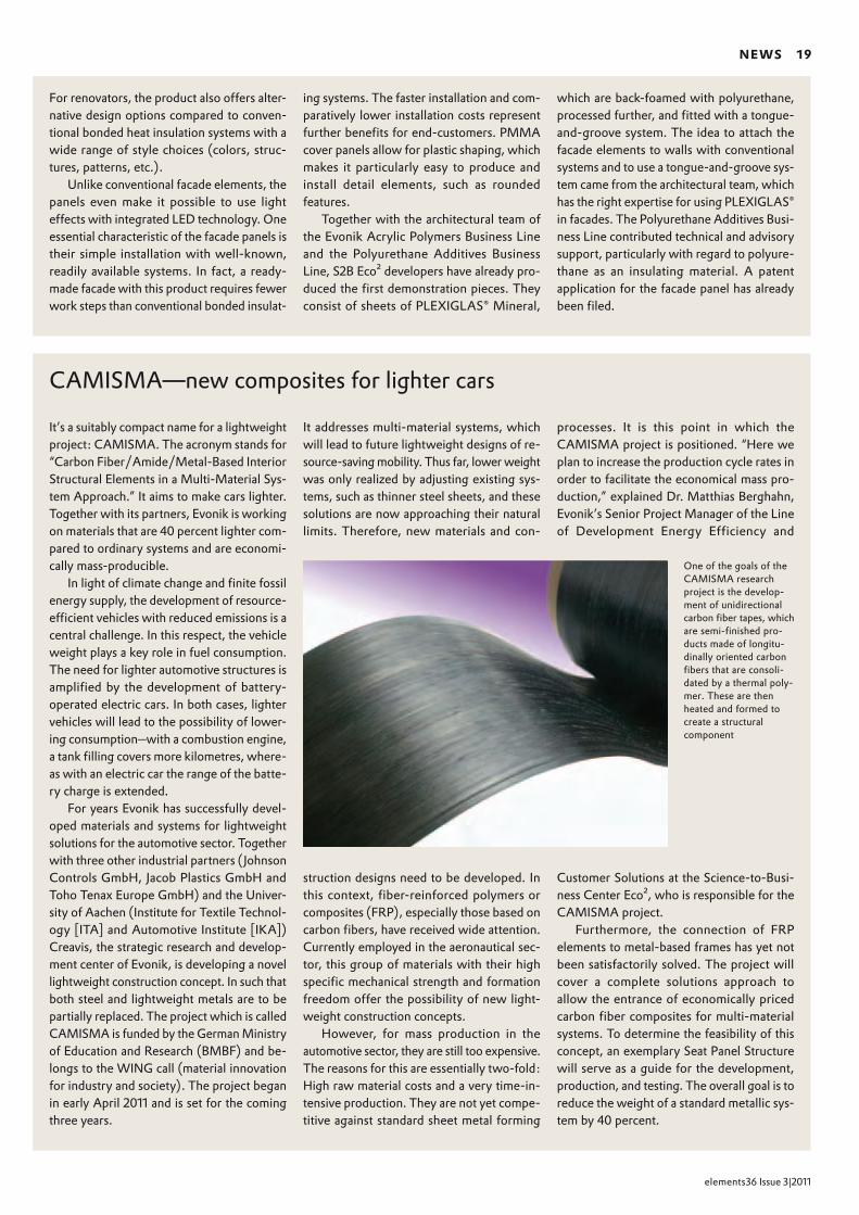
It’s a suitably compact name for a lightweight project: CAMISMA. The acronym stands for “Carbon Fiber/Amide/Metal-Based Interior Structural Elements in a Multi-Material Sys-tem Approach.” It aims to make cars lighter. Together with its partners, Evonik is work ing on materials that are 40 percent lighter com-pared to ordinary systems and are economi-cally mass-producible.
In light of climate change and finite fossil energy supply, the development of re source-efficient vehicles with reduced emissions is a central challenge. In this respect, the vehicle weight plays a key role in fuel consumption. The need for lighter automotive structures is amplified by the de vel opment of battery-operated electric cars. In both cases, lighter vehicles will lead to the possibility of lower-ing consumption—with a combustion engine, a tank filling covers more kilometres, where-as with an electric car the range of the batte-ry charge is extended.
For years Evonik has successfully devel-oped materials and systems for lightweight solutions for the automotive sector. Together with three other industrial partners (Johnson Controls GmbH, Jacob Plastics GmbH and Toho Tenax Europe GmbH) and the Uni ver-sity of Aachen (Institute for Textile Technol-ogy [ITA] and Automotive Institute [IKA]) Creavis, the strategic research and develop-ment center of Evonik, is developing a novel lightweight construction concept. In such that both steel and lightweight metals are to be partially replaced. The project which is called CAMISMA is funded by the German Ministry of Education and Research (BMBF) and be-longs to the WING call (material innovation for industry and society). The project began in early April 2011 and is set for the com ing three years.
It addresses multi-material systems, which will lead to future lightweight designs of re-source-saving mobility. Thus far, lower weight was only realized by adjusting exist ing sys-tems, such as thinner steel sheets, and these solutions are now ap proaching their natural limits. Therefore, new materials and con-
struction designs need to be developed. In this context, fiber-re in forced polymers or composites (FRP), especially those based on carbon fibers, have received wide attention. Currently em ployed in the aeronautical sec-tor, this group of mat erials with their high specific mechan ical strength and formation freedom offer the possibility of new light-weight construction concepts.
However, for mass production in the automotive sector, they are still too expensive. The reasons for this are essentially two-fold: High raw material costs and a very time-in-tensive production. They are not yet compe-titive against standard sheet metal forming
For renovators, the product also offers alter-native design options compared to conven-tional bonded heat insulation systems with a wide range of style choices (colors, struc-tures, patterns, etc.).
Unlike conventional facade elements, the panels even make it possible to use light effects with integrated LED technology. One essential characteristic of the facade panels is their simple installation with well-known, readily available systems. In fact, a ready- made facade with this product requires fewer work steps than conventional bonded insulat-
ing systems. The faster installation and com-paratively lower installation costs represent further benefits for end-customers. PMMA cover panels allow for plastic shaping, which makes it particularly easy to produce and install detail elements, such as rounded features.
Together with the architectural team of the Evonik Acrylic Polymers Business Line and the Polyurethane Additives Business Line, S2B Eco² developers have already pro-duced the first demonstration pieces. They consist of sheets of PLEXIGLAS® Min eral,
which are back-foamed with poly ur ethane, processed further, and fitted with a tongue-and-groove system. The idea to attach the facade elements to walls with conventional systems and to use a tongue-and-groove sys-tem came from the architectural team, which has the right expertise for using PLEXIGLAS® in facades. The Poly ur ethane Additives Bu si-ness Line contributed technical and advisory support, particularly with regard to polyure-thane as an insulating material. A patent application for the facade panel has already been filed.
One of the goals of the CAMISMA research project is the development of unidirectional carbon fiber tapes, which are semifinished products made of longitudinally oriented carbon fibers that are consolidated by a thermal polymer. These are then heated and formed to create a structural component
processes. It is this point in which the CAMISMA project is positioned. “Here we plan to increase the production cycle rates in order to facilitate the economical mass pro-duction,” explained Dr. Matthias Berg hahn, Evonik’s Senior Project Manager of the Line of Development Energy Efficiency and
Customer Solutions at the Science-to-Bu si-ness Center Eco², who is responsible for the CAMISMA project.
Furthermore, the connection of FRP elements to metal-based frames has yet not been satisfactorily solved. The project will cover a complete solutions approach to allow the entrance of economically priced carbon fiber composites for multi-material systems. To determine the feasibility of this concept, an exemplary Seat Panel Structure will serve as a guide for the development, production, and testing. The overall goal is to reduce the weight of a standard metallic sys-tem by 40 percent.

20 CAtALYsis
elements36 Issue3|2011
LinDLAr CAtALYsts Are the method of choice for hydro-genating alkynes to cis-alkenes. Corresponding amine-modified (quinoline) palladium (Pd) catalysts deposited on CaCO3 that are partially poisoned with lead are not only suitable for hydroge-nating alkynes, but also for selective hydrogenation of alkenes and unsaturated aldehydes as well as for generating boc-pro-tected (t-butyloxycarbonyl-protected) amines from azides. The Evonik product portfolio offers a particularly powerful variation of lead-doped Pd catalysts for these types of applications.
The use of lead, which was long considered a necessity be-cause it allows for high stereoselectivity, can be a drawback from an environmental perspective. To address this issue, Evonik has developed a lead-free alternative for the hydrogenation of al kynes to cis-alkenes.
Shape and size of Pd nanoparticles determine selectivityThis development is based on state-of-the-art scientific insights according to which the selectivity of the catalysts is not con-trolled by lead, but by the shape and size of Pd nanoparticles. For this purpose, the Pd crystallites must be very small to ensure the presence of coordinative unsaturated surface sites. These surface sites make it possible to vary the electronic properties of the Pd grid and allow the integration of non-toxic foreign atoms in such a way that the solubility of hydrogen is reduced in the Pd phase. Since the hydrogen dissolved in the Pd grid is respons ible for the non-selective hydrogenation reactions—the
Lindlar catalysts: A lead-free alternativeEvonik has developed a technology for the stereoselective hydrogenation of carbon triple bonds to carbon double bonds with Lindlar catalysts that elimi-nates the use of lead. In comparison with conventional leaded Lindlar catalysts, the new catalysts also stand out for their catalytic properties. They are equally selective, but show a significantly higher activity with a lower palladium load.
[ text Dr. Dorit Wolf ]

CAtALYsis 21
elements36 Issue 3|2011
777
Lindlar catalysts: A lead-free alternativecomplete hydrogenation to alkane—catalysts with such a modi-fication show significantly improved selectivity.
This principle can be applied to a variety of support materi-als (oxidic and activated carbon). However, this presumes that the tiny Pd particles remain accessible to the substrates and do not disappear in the micropore structure of, for instance, acti-vated carbon.
Colloid technology enables customized activity and selectivityEvonik uses colloid technology to develop a corresponding man-ufacturing process for catalysts. Compared to the Lindlar tech-nology, this approach allows almost five times the activity, with the corresponding reduction of the Pd load. The selectivity of the resulting catalysts in the transformation of alkynes to cis-alkenes reaches a high level that is comparable to conventional Lindlar catalysts.
A simple model reaction, the stereoselective hydrogenation of 2-hexine to cis-2-hexene (Fig. 1), highlights the performance capabilities of lead-free catalysts. While the lead-doped Lind-lar catalyst has a Pd load of 5 percent, the precious metal load of colloid-based, lead-free systems was reduced to 1 percent without any decrease in activity. At the same time, the process achieves very high levels of stereoselectivity and the corres-ponding yields of cis-2-hexene (Fig. 2–4). Currently this tech-nology is being optimized for various industrially relevant sub-strates.
PD Dr. Dorit Wolf has been R&D group leader in Evonik’s Catalysts Business Line since 2004. She studied chemistry at the University of Leipzig, where she earned her doctorate in 1991. In 1997, Wolf qualified as a university lecturer in chemical technology at the Chair for Chemical Technology at Ruhr University in Bochum. She subsequently accepted a position as director of the Reaction Technology Working Group at the Institute for Applied Chemistry Berlin-Adlershof. In 2001 she moved to Evonik to direct the Heterogeneous Catalysis Group in the Catalysis Project House.+49 6181 [email protected]
Figure 1
Stereoselective hydrogenation of 2-hexine to cis-2-hexene
Figure 2–4
The illustration shows the product distribution for the conversion of 2-hexine to cis-2-hexene, trans-2-hexene and hexane for a classic Lindlar catalyst (left) and for the newly developed, colloid-based systems: Pd/CaCO3 (center) or Pd/C (right)
2-Hexine cis-2-Hexene trans-2-Hexene Hexane
Lindlar (5% Pd and 3,5% Pb/CaCO3)Molar fraction [%]
[1] Lindlar, H.: Helv. Chim. Acta 1952, 35, 446[2] Ghosh, A. K.; Krishnan, K.: Tetrahedron Letters 1998, 39, 947[3] Righi, G.; Rossi, L.: Synthetic Communications 1996, 26, 1321[4] Teschner, D. et al.: J. Catal. 2006, 242, 26[5] Klasovsky, F.; Wolf, D.: Top. Catal. 2009, 52, 412–423
reFerenCes
Catalyst Catalyst
H2 H2
1% Pd/CaCO3
Molar fraction [%]1% Pb/CMolar fraction [%]
10080604020
0
200160
0
20
40
60
80
100
40 80 120
●
●
●
●
●
●
●
●
●
●
0
●
Time [min]
0●●
100
80
60
40
20
45 90 135 180 225
●●●●
●
●●●● ●
●●
0
●
Time [min]
●●
100
80
60
40
20
●
●
●
●
●
●
●●
●
●
●
●
●●●●●●
● ●●●
0
●
●
Time [min]
●
●
●
●
●
●
●
● ●●
●
●
●●● ● ● ● ● ● ●● ●
●
● ● ● ●●●●●
● ●●●●●
●
●● ● ● ●
●●
● ● ●
●●●●●●● ●●●●● ●●●●● ●●●●●●●

22 LiFe CYCLe Assessment
elements36 Issue 3|2011
333
e10 Yes or no? The debate over the bioethanol-gasoline mix-ture dominated the headlines in Germany for weeks. What have we learned from this incident? Consumers are a bit doubtful when the advantages of a new product are not clearly commu-nicated to them—bio-based or not. Today’s raw material and pro-duction chains are so complex that no one can say right off just how eco-friendly a product with “bio” in its name actually is.
Only a few years ago, hardly anyone would have wondered whether the additional bioethanol in German fuel tanks might have a negative impact somewhere else in the world—for in-stance, if forests or pastureland were converted to cropland for growing plant-based raw materials for alcohol production. Or if urgently needed food ultimately ended up in the tank instead of on the plate.
Today, nearly all innovative segments recognize the need to see the whole picture. The chemical industry is no different. In the development of new products or improvement of existing ones, the focus is no longer on economic added value alone. The key questions are now completely different: How eco-friendly
Life cycle thinking: An in-house team of experts evaluates the entire life cycle of new products and processes
A precise view of the whole picture
and climate-compatible is the entire value-added chain? Is the entire life cycle really sustainable? And exactly how much do “new” and “old” differ in terms of their environmental impact?
Life cycle assessment and carbon footprintThe instrument needed to answer these questions has been available for years: The life cycle assessment (LCA), which sys-tematically analyzes the impact of products and process chains on the environment. Depending on the specific question, a life cycle assessment can analyze and balance the entire life cycle of a product, from raw material extraction, through production of the required energy, material production, transport, application and use, to recycling or final disposal. Life cycle thinking can help compare various process routes for the same product or else compare alternatives with the same customer benefit. In ad-dition, life cycle assessments expose weak spots and indicate potential for improvement of environmental properties in the various phases of the value-added chain.
Today’s chemical products can no longer be described in terms of quantities and market price alone. Experts from Evonik use life cycle assessments and carbon footprints to analyze the complete life cycle. Such life cycle thinking allows a company to tightly integrate ecology and profitability beyond corporate boundaries.
[ text Thomas Engenhorst, Dr. Karsten Grönke ]

LiFe CYCLe Assessment 23
elements36 Issue 3|2011
. . .
Ozone depletion
Eutrophication
Acidification
Global warming
. . .
Ozone depletion
Eutrophication
Acidification
Global warmingAcidification
. . .
Ozone depletion
Eutrophication
Global warming
. . .
Ozone depletion
Eutrophication
Acidification
Global warming
How environmentally compatible and climatefriendly is the entire value added chain of a product—e. g. for heat insulation—, from its raw materials, through production, to disposal? Is the entire life cycle really sustainable? A life cycle assessment supplies the answers
Life cycle assessments examine the individual phases of the product’s life cycle, as well as all of its environmental aspects
Product use
Raw materials
Production
End-of-life recycle/disposal
Gate to gate
Cradle to gate
Cradle to cradle/grave
Impa
ct c
ateg
orie
s
Life cycle

24 LiFe CYCLe Assessment
elements36 Issue 3|2011
Although a life cycle assessment can analyze a variety of en-vironmental effects on products and services, public debate in recent years has focused primarily on their relevance to climate protection. International experts have developed special methods for calculating a specific product’s “carbon footprint” for the purpose of balancing greenhouse gases. A way of measuring all greenhouse gases (expressed as CO2 equivalents, CO2e) that occur in the life cycle of a particular product, the carbon foot-print is an effective tool for determining, assessing, and commu-nicating the climate effectiveness of goods and services.
LCA and the carbon footprint have become internationally recognized tools. LCAs are based on ISO standard 14040, as is the carbon footprint. However, for the carbon footprint there is currently the additional ISO standard 14067 in progress that will be published in 2012. The reason is that the carbon footprint has developed into a guide value within an LCA, and is currently considered the most important indicator, both politically and internationally. Accordingly, awareness of the climate relevance of products and services is increasing among companies and their suppliers and customers. This is why life cycle assessments and the carbon footprint are valuable marketing tools and, at the same time, important building blocks for the company itself in its development of a sustainable corporate strategy.
Customers want to knowThis subject has taken on enormous importance in a relatively short period at Evonik, too. In its Science-to-Business (S2B) Cen-ter Eco² at Creavis Technologies & Innovation, the company has established a nine-person team of LCA experts to focus on pro-jects on the megatrends concerning climate and energy. The
team is composed of scientists and engineers with various back-grounds from the Process Technology & Engineering Service Unit. Its task is to develop cross-Group LCA standards, evaluate Evonik products and processes for their sustainability and climate relevance, and support LCA experts in the individual business units with internal process analyses and customer- focused studies.
The reason is not surprising: With its large product port folio, Evonik relies on a number of imported raw materials that differ widely in terms of their environmental and climate relevance, as well as the methods used to obtain and produce them. An international company like Evonik can play a large role in im-prov ing the value-added chains ecologically through its close rela tionships with raw materials suppliers on the one hand and customers on the other.
This goal is reflected in the very specific questions experts and developers at Evonik are trying to answer: How can products and processes be made more sustainable? What is the carbon footprint of a particular chemical? How much CO2 will a cus-tom er save by using an improved product? What is the most effi-cient way for the entire company to reduce its greenhouse gases?
The experts are not grappling with these kinds of questions out of altruism. On the contrary: Year after year, the number of specific customer inquiries is growing. This is especially true of business units that supply their products to the consumer goods industry or that operate in CO2-sensitive markets such as the automobile industry. A welcome side-effect of working with life cycles and the climate relevance of products is that it often results in a partnership between Evonik and customers, in which both parties are looking for an answer to the question of how to further improve products.
333
The LCA Group uses Carbon Footprint Estimation, a method developed inhouse and certified by independent auditor PricewaterhouseCoopers, to analyze all the projects of S2B Eco² in the research and development stage

LiFe CYCLe Assessment 25
elements36 Issue 3|2011
Life-cycle thinking begins as early as the laboratory, where developers first entertain the idea of new or improved products and processes. Since 2009, the LCA group has taken a close look at all the projects of S2B Eco² in the research and development stage and developed life cycle assessments and carbon footprints not only for its research projects but for the projects planned by the various business units in the Group. The fact that something is new does not necessarily make it sustainable. And to make sure an economic benefit accompanies the environmental added value, the issues essential to a good life cycle assessment must be addressed at an early stage.
But how do you conduct such analyses when the new product or improved process still exists only in the laboratory stage? In this early phase, a number of conditions are still unclear—for example, at what stage production will begin, what kind of yields the process will have on the commercial scale, and what the spe-cific mix of energies will be when production begins.
For calculations at this early stage, the LCA group in S2B Eco² developed the Carbon Footprint Estimation (CFE) method. This method allows a standardized evaluation of research projects at every stage, and thereby ensures that different Evonik product developments are assessed on the basis of comparable criteria. The model allows for a variety of possibilities for minimizing the risk of incomplete or faulty data by such techniques as iterative expert checks and making conservative assumptions. Checked by independent auditor PricewaterhouseCoopers (PwC), the methodology focuses primarily on climate impact but can also be expanded to include environmental or social factors. It can also be applied to specific issues in other areas of R&D.
In the CFE method, the projects of S2B Eco² go through a multi-stage, iterative process and must prove that they have a
positive influence on the climate at every stage of their develop-ment. The decisive question in these analyses is whether the new product or improved production process is able to save a given amount of CO2 equivalents over its entire life cycle. The research project receives the green light in this dimension only if this question can be answered with a “yes.”
Amino acid diet for more sustainable animal feed A life cycle assessment in itself is of limited use. Its value always lies in direct comparison—ideally, with a product that is already established on the market or serves the same purpose. One im-pressive example is the comparison of various feeds for pigs or chickens. Evonik produces all four of the important amino acids for modern animal nutrition that essentially determine how efficiently the protein in the feed can be utilized. Because con-ventional plant-based animal feeds are always deficient in one or more amino acids, the animals normally require more feed. As a result, they produce more manure, which pollutes the groundwater with nitrate and the air with ammonia. On the other hand, if animal feed can be made to offer a customized range of amino acids, it will do more than just ensure optimal care of the animals. It will also reduce both the nitrogenous emis-sions and the greenhouse gases from agricultural food produc-tion (e. g. agriculture, processing, etc.) in the entire life cycle.
In extensive life cycle assessments, Evonik’s experts have proven that selectively adding certain amino acids to feed provides significant advantages over supplementing them with protein-rich rapeseed or soy meal (see elements33, p. 8). In the case of pork feed, for example, they have calculated that 333
Greenhouse gases are the focus of the Carbon Footprint Estimation method, which estimates emissions in terms of CO2 equivalents over the entire life cycle
By-product
Product
Process-related CO2e emissions
Production process
Thermal recovery
Product use End of life
Recycling
Disposal
Cradle to gate Gate to grave
CO2e burden
Thermal energy Power
Raw materials
Transport

26 LiFe CYCLe Assessment
elements36 Issue 3|2011
Evonik’s “ecocalculator,” the AminoFootprint™: With this software, customers from the animal feed industry can compare the environmental impact of various animal feed mixtures over their entire life cycle

LiFe CYCLe Assessment 27
elements36 Issue 3|2011
333
the CO2 equivalents are lower by a factor of two to five, the acidification potential by a factor of 12, and the eutrophication potential by a factor of 16.
Adding amino acids to feed mixtures replaces vegetable resources and, therefore, reduces the need for cultivation areas. In addition, less energy has to be used for preparing and provid-ing the required raw materials. In cooperation with the Health & Nutrition Business Unit the LCA Group developed the Amino-Footprint™ software to assist the business unit’s customers in the environmental evaluation of different animal feed mixtures over the entire life cycle.
High-quality polymers from castor oilMany life cycle assessments in the chemical industry ask “bio or fossil?” In other words, they seek to compare bio-based raw ma-terials with oil-, gas-, or coal-based raw materials. Bio-based raw materials are becoming increasingly important even in tech-nically demanding fields of applications. Their advantage can be a more favorable CO2 footprint. If plant-based ingredients are converted in chemical processes and further processed, energy is inevitably consumed and carbon dioxide is generated. Depend-ing on the efficiency of the process, more or less than the amount of the CO2 that was previously absorbed by the plant during its growth is released.
Polymer chains can also be synthesized, completely or in part, from bio-based components. Among the Evonik polyamides that have long since proven themselves on the market are the VESTAMID® product family of the Performance Polymers Busi-ness Unit. They are primarily used for long-lasting and techni-cally demanding applications: For fuel and brake lines in cars, for oil delivery lines and gas pressure pipes, and for the soles of high-quality sports shoes and anti-electrostatic device housings.
In a plant operated south of Shanghai since 2008, Evonik pro-duces a line of monomers from castor oil for several bio-based polyamides marketed under the name VESTAMID® Terra. According to calculations, the global warming potential of
VESTAMID® Terra HS (Polyamide 610), for example, is lower than it is with the chemically similar and fossil-based Polyamide 6 (“Perlon,” comparison based on data taken from the literature). If the production process for the plastic is further optimized, emissions—expressed as CO2 equivalents—drop by 15 to 20 percent.
In recent years, renewable raw materials such as vegetable oils and sugar have carved out a solid niche in the spectrum of substances used in the chemical industry. Approximately 7 per-cent of all starting materials currently used at Evonik are bio-based. There is a lot to be said for raw materials from the field: Their supply is infinite. Frequently, they have a good image among customers and end-users, in politics, and the media. Nature has also created—particularly in plants—an exceedingly wide variety of substances whose potential remains largely un-tapped by the chemical industry.
It is unlikely that the chemical industry is facing a similar debate like E10. Compared to the fuel-producing industry, the chemical industry needs far fewer quantities of plant-based raw materials. In a large-scale study by the International Council of Chemical Associations (www.icca-chem.org), it was shown that the chemical industry offers many products and solutions that result in a reduction of greenhouse gases. The use of new high-performance polymers in automobile construction, for example, can help reduce vehicle weight and thus lower fuel consumption.
“Bio” is not always more ecologicalBut being “bio-based” does not necessarily make something sustainable and more environmentally compatible than tradi-tional chemistry. For example, a bio-based product is not practi-cal if the use of renewable raw materials requires a particularly high energy input, or if damaging or toxic emissions are released during the life cycle of the product.
Sometimes, LCA experts find renewables hard to assess, because regional differences and the often poor quality of the data result in a wide variety of results. In addition, various
333
The tropical castoroil plant (Ricinus communis) as a source of raw mate r ials: In Shanghai, Evonik produces monomers for biobased polyamides from castor oil obtained from the plant’s seeds
VESTAMID® Terra HSPA 61062% based on biorenewables
H
N
H
N
O On
6 8
VESTAMID® Terra DSPA 1010100% based on biorenewables
H
N
H
N
O On
10 8
VESTAMID® Terra DDPA 101245% based on biorenewables
H
N
H
N
O On
10 10

28 LiFe CYCLe Assessment
elements36 Issue 3|2011
oiliness. The life cycle assessment speaks loud and clear. Comparison of the produc-tion of an emollient ester using lipase B from a Candida bacterium with a conven-tional synthesis at 220°C with tin salts as the catalyst reveals that the biocatalytic method saves more than 60 percent in energy and 88 percent in environmentally harmful impurities.
Despite this kind of success, the over-whelming majority of today’s chemical pro-ducts are still synthesized by the traditional method. This is because biotechnological
Chemical or bio? Chemical and bio!
For many years, there has been a perceived conflict between “chemical” and “bio.” One typically refers to production with organic solvents under high pressure and temperatures, the other to the biotechnol-ogical processes in which special microor-ganisms or the enzymes isolated from them generate the desired raw materials in an aqueous solution under gentle conditions.
As a matter of fact, biotechnological processes have made great strides. They are more efficient and economical today than they were a few years ago. Normally, they
more sustAinABLe CHemistrY
save energy, generate little waste, and pose minimal risk to humans and the environ-ment.
Evonik exploits this potential for such processes as the biotechnological produc-tion of emollient esters, which are impor-tant ingredients for numerous skin care products. For six of these esters, Evonik is the only supplier worldwide with bio-technological production based on custom-tailored enzymes. The newest product of this series, TEGOSOFT® AC, is charac-terized by a particular lightness and low
Can waste wood be completely utilized for chemical products? A research association made up of 20 partners, including Evonik, is exploring this question in Leuna (Germany)
Flow chart of the enzymatic and chemical production processes for emollient esters compared by Evonik based on a life cycle assess-ment
Raw materials
Reaction
Deodorization
Bleaching
Drying
Filtration
Packaging
Catalyst
Steam
Bleach
Filter aid
Volatile compounds
Aqueous waste
Aqueous waste
Solid waste
Conventional
Applied temperature
> 180°C
140°C
100°C
60°C
20°C
Raw materials
Reaction
Enzymatic
Packaging
Catalyst recycled
LiFe CYCLe Assessment 29
elements36 Issue 3|2011
777
thomas engenhorst studied bioengineering at Braun -schweig Technical University, spending a year at the University of Waterloo in Canada with a grant from the German Academic Exchange Service (DAAD). He has worked in Evonik’s Process Technology & Engineering Service Unit since 2008. In addition to handling bio-engineering questions, he is the member of the LCA group respons ible for coordinating, conducting, and re fining life cycle assessments and their use among cus tomers, industry associations, and as part of devel-opment projects.+49 6181 59-3865, [email protected]
Dr. Karsten Grönke studied process engineering at the Technical University of Cottbus in Germany. After spending a year abroad studying biotechnology at the Technical University of Delft in the Netherlands, writing his thesis in bioprocess engineering at Bayer AG, and then going on to do a doctorate in fermenta-tion engineering at the Institute for Biotechnology at the Jülich Research Center, Dr. Grönke has worked in biotechnology process development in the Process Technology & Engineering Service Unit since 2006. In the LCA group, he also develops LCA methods in S2B Eco² and prepares life cycle assessments for Evonik’s products and research projects. +49 2365 49-2384, [email protected]
more sustAinABLe CHemistrY
processes take a long time to develop, it is complex to process, purify, and concentrate the biochemicals generated, and the sensi-tive cells or enzymes are not always easy to handle.
Chemical or bio? This question is not even asked in many cases. In the future, the ideal answer will be “a combination of the two.” When chemical and biological syn-the ses are integrated, both disciplines can combine their strengths: Chemistry for converting large volumes and synthesizing simple molecules, and biology for forming complex structures and converting raw materials that are hard to split.
Biorefineries could be the gateway for this new partnership. Like petrochemical refineries, these facilities produce com -plet e ly different chemicals, raw materials and fuels “cascade style”—but from bio-mass instead of crude oil. Second-gener a-tion biorefineries no longer process only starches and sugar, as their predecessors did, but lignocellulosic materials from plant waste such as straw and bagasse, the fibrous remains of sugar production.
Evonik is participating in a 20-partner-strong research network with plans to com-mission a 100-metric-ton pilot plant at the Leuna chemical site. In the three-year pilot phase, the project will test the complete utilization of waste wood in chemical prod ucts and lay the groundwork for processes suitable for industrial application. If valu-able raw materials can be produced from materials that were previously good for nothing more than waste or cheap fuels, it would be a great leap forward—not only for white biotechnology as a discipline but for more sustainable chemistry in general.
committees are still working on standardizing the methodol-ogy. This is why an objective description, including all parame-ters, and interpretation of the results is so vitally important.
On the other hand, the results for fossil raw materials are quite traceable and display relatively few deviations. Companies specialized in life cycle assessments have now developed soft-ware packages that pull together the many influencing factors into a workable relationship. For its calculations, Evonik uses a software called GaBi, developed by PE International in Stutt-gart—the market leader in life cycle assessment modules for industrial processes.
Despite all questions that life cycle assessments and carbon footprint currently raise, we are convinced that in five to ten years, the holistic balancing of alternative raw materials and new products and processes will be firmly anchored in the daily rou-tine of the chemical industry. Until then, standardization will continue to evolve. The transparency, credibility, comparability, and reliability of the results will increase.
But make no mistake, life cycle thinking is by no means an easy challenge. We stand at the threshold of a groundbreaking development. Sooner or later, the chemical industry will have to redevelop its entire raw materials base. It will have to replace its finite fossil raw materials with renewable raw materials whenever possible and useful—and not just through a simple exchange but through economic and deft integration into its existing production chains.
LCAs and the carbon footprint help us see the whole picture, understand relationships, evaluate individual parts of a value-added chain, and uncover weak spots. Put another way, they foster holistic thinking—a necessity in a world with increasingly complex raw material and product streams, with growing requirements for environmental and climate protection, and an obligation to use existing raw materials as sparingly, intelligently, and efficiently as possible.
333
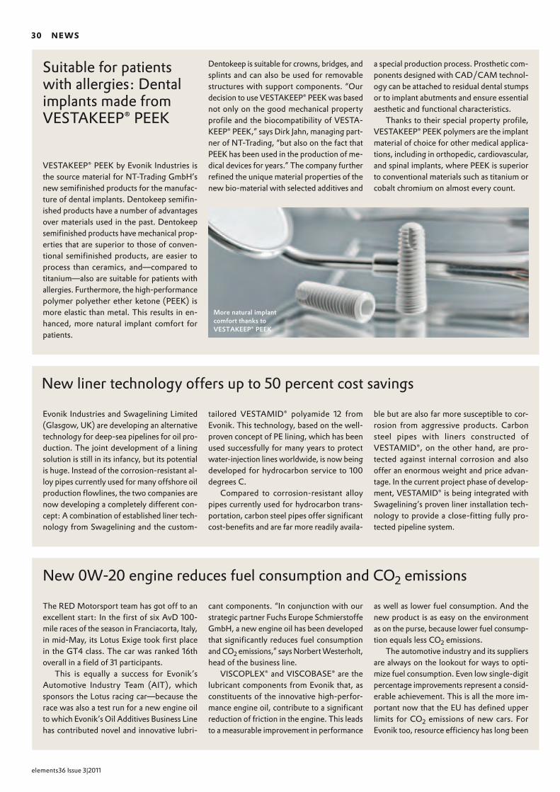
30 neWs
elements36 Issue 3|2011
Suitable for patients with allergies: Dental implants made from VESTAKEEP® PEEK
VESTAKEEP® PEEK by Evonik Industries is the source material for NT-Trading GmbH’s new semifinished products for the manufac-ture of dental implants. Dentokeep semifin-ished products have a number of advantages over materials used in the past. Dentokeep semifinished products have mechanical prop-erties that are superior to those of conven-tional semifinished products, are easier to process than ceramics, and—compared to titanium—also are suitable for patients with allergies. Furthermore, the high-performance polymer polyether ether ketone (PEEK) is more elastic than metal. This results in en-hanced, more natural implant comfort for patients.
Dentokeep is suitable for crowns, bridges, and splints and can also be used for removable structures with support components. “Our decision to use VESTAKEEP® PEEK was based not only on the good mechanical property profile and the biocompatibility of VESTA-KEEP® PEEK,” says Dirk Jahn, managing part-ner of NT-Trading, “but also on the fact that PEEK has been used in the production of me-dical devices for years.” The company further re fined the unique material properties of the new bio-material with selected additives and
a special production process. Prosthetic com-ponents designed with CAD/CAM technol-ogy can be attached to residual dental stumps or to implant abutments and ensure essential aesthetic and functional characteristics.
Thanks to their special property profile, VESTAKEEP® PEEK polymers are the implant material of choice for other medical applica-tions, including in orthopedic, cardiovascular, and spinal implants, where PEEK is superior to conventional materials such as titanium or cobalt chromium on almost every count.
More natural implant comfort thanks to VESTAKEEP® PEEK
New liner technology offers up to 50 percent cost savings
Evonik Industries and Swagelining Limited (Glasgow, UK) are developing an alternative technology for deep-sea pipelines for oil pro-duction. The joint development of a lining solution is still in its infancy, but its potential is huge. Instead of the corrosion-resistant al-loy pipes currently used for many offshore oil production flowlines, the two companies are now developing a completely different con-cept: A combination of established liner tech-nology from Swagelining and the custom-
tailored VESTAMID® polyamide 12 from Evonik. This technology, based on the well- proven concept of PE lining, which has been used successfully for many years to protect water-injection lines worldwide, is now being developed for hydrocarbon service to 100 degrees C.
Compared to corrosion-resistant alloy pipes currently used for hydrocarbon trans-portation, carbon steel pipes offer significant cost-benefits and are far more readily availa-
ble but are also far more susceptible to cor-rosion from aggressive products. Carbon steel pipes with liners constructed of VESTAMID®, on the other hand, are pro - tect ed against internal corrosion and also offer an enormous weight and price advan-tage. In the current project phase of develop-ment, VESTAMID® is being integrated with Swagelining’s proven liner installation tech-nology to provide a close-fitting fully pro-tected pipeline system.
New 0W-20 engine reduces fuel consumption and CO2 emissions
The RED Motorsport team has got off to an excellent start: In the first of six AvD 100-mile races of the season in Franciacorta, Italy, in mid-May, its Lotus Exige took first place in the GT4 class. The car was ranked 16th overall in a field of 31 participants.
This is equally a success for Evonik’s Automotive Industry Team (AIT), which sponsors the Lotus racing car—because the race was also a test run for a new engine oil to which Evonik’s Oil Additives Business Line has contributed novel and innovative lubri-
cant components. “In conjunction with our strategic partner Fuchs Europe Schmierstoffe GmbH, a new engine oil has been developed that significantly reduces fuel consumption and CO2 emissions,” says Norbert Westerholt, head of the business line.
VISCOPLEX® and VISCOBASE® are the lubricant components from Evonik that, as constituents of the innovative high-perfor-mance engine oil, contribute to a significant reduction of friction in the engine. This leads to a measurable improvement in performance
as well as lower fuel consumption. And the new product is as easy on the environment as on the purse, because lower fuel consump-tion equals less CO2 emissions.
The automotive industry and its suppliers are always on the lookout for ways to opti-mize fuel consumption. Even low single-digit percentage improvements represent a consid-erable achievement. This is all the more im-portant now that the EU has defined upper limits for CO2 emissions of new cars. For Evonik too, resource efficiency has long been

neWs 31
elements36 Issue 3|2011
Took first place in the GT4 class in the first AvD 100-mile race of the season: The Lotus Exige
Glycine capacity expanded
Evonik Industries has increased its production capacity for the pharmaceutical amino acid glycine by 50 percent due to rising demand. This was achieved by efficiency gains in the production process. Evonik manufactures the amino acid at its Chinese Nanning site in accordance with the strict requirements of cGMP (current Good Manufacturing Prac-tice) and the European Pharmacopoeia (CEP; Certificate of Suitability of Mono graphs of the EuropeanPharmacopoeia). Evonik is in-vesting in a new plant in Nanning to expand its portfolio of specialty chemical products by milling and sieving processes. The new quali-ties are expected to come on the market at the end of the year.
“We’re currently experiencing strong demand for our glycine,” reports Dr. Thomas Hermann, head of the Rexim Product Line. “By increasing our production capacities, we can keep up with this demand and further solidify our excellent market position.”
By upgrading its technologies particularly in the purification process, Evonik has further improved product quality. “We’re now able to provide glycine in all crystalline forms and particle size distributions requested by customers,” notes Dr. Jean-Louis Philippe,
the responsible marketing manager for the pharmaceutical amino acids.
Glycine is primarily used in the phar ma-ceu tical and food industry, but also in pet food. It is a component of infusion solutions and specialty nutrition items and is also part of cell culture media. Accordingly, Evonik offers glycine in pharmaceutical and food-grade quality.
The wholly owned Evonik subsidiary Rexim is a significant producer of amino acids, peptides, and amino acid derivatives in pharmaceutical quality. The company acquired the glycine business of the Belgian Tessen derlo Group last year to further ex-pand this business. The products are pri mar-ily used in the pharmaceutical industry, in-cluding in infusion solutions and to manu-facture active pharmaceutical ingredients for anti-hypertensive and diabetes drugs, but also have many applications in the cosmetics and food industry.
Evonik’s strengths include its global dis-tribution network and cGMP-compliant manufacturing across the entire supply chain, ranging all the way to cGMP-compliant amino acid purification.
an important target. So it was no coincidence that lubricants producer Fuchs turned to Evonik when looking for new components—and found what it wanted.
Thanks to a sophisticated development process, the new 0W-20 engine oil was at the starting line promptly at the opening of the racing season. “Because the technical re-quirements of the individual components were extremely high, we had to partly rede-velop the products before producing them,” says Dr. Thorsten Bartels, head of the test laboratory for Oil Additives at Evonik in Darmstadt. Over the last year, Bartels and his team have optimized the newly developed high-performance lubricant on an engine test-bench and also tested it in racing cars under realistic driving conditions on a num-ber of test tracks until it was finally ready for use in racing.
In the Lotus Exige, Evonik’s Automotive Industry Team regularly makes use of inno-vative technologies for automotive construc-tion, in lubricant additives and fuel sav ing as well as other areas of expertise such as light-weight design and surface technol ogies. The
Lotus model constructed for this season weighs in at just 780 kilograms. The reduced weight results from the use of various Evonik technologies such as the structurally rigid ROHACELL® foam core in the bodywork.
For the AIT, which brings together the Group’s automotive experts, motor sports serve as the test field for series production: “Only those technologies that withstand the
rigorous conditions of the race track can be considered basically suitable for serially produced vehicles,” says AIT head Klaus He drich. Meanwhile, testing of the newly developed oil on the engine test-bench and roller dynamometer continues at Evonik in Darmstadt (Germany). The innovative lubri-cant is already undergoing long-term tests in a fleet of road vehicles.
Amongst others, glycine is used as a component of infusion solutions

32 CoAtinG & BonDinG teCHnoLoGies
elements36 Issue 3|2011
UV-cured coatings
Greater matting freedom
UV-cured coatings are primarily used to coat smooth surfaces or battens. Examples include the furniture industry, high-quality printed material or the production of films
Conventional, solvent-based coatings can be matted relatively easily—unlike UV-cured coatings. With a comprehensive series of tests, Evonik has completed foundational work and shown how these coatings can be matted more effectively. The visible result is the new matting agent ACEMATT® 3600, which allows greater freedom in the formulation of matt UV coatings.
[ text Reinhard Behl, Hans-Dieter Christian ]
The advantage of UVcured coatings is not only that they require little energy but also little time to cure—the coated object is ready for downstream process ing just a few seconds after curing
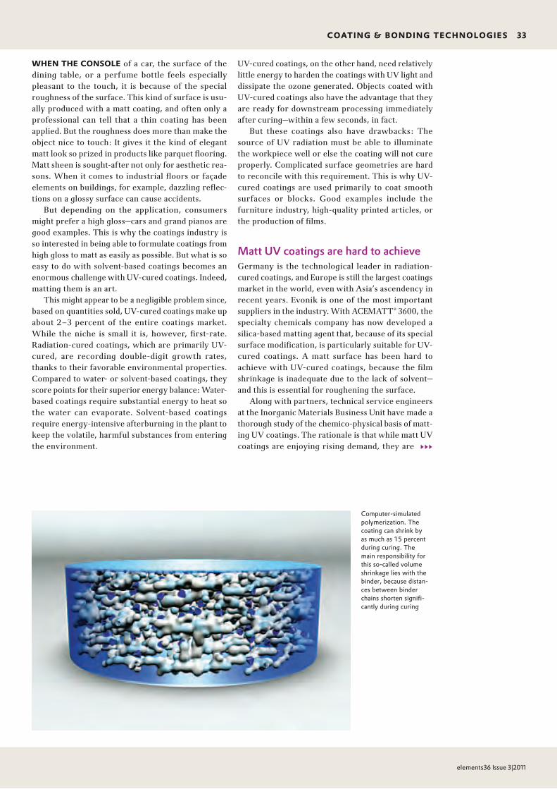
CoAtinG & BonDinG teCHnoLoGies 33
elements36 Issue 3|2011
333
WHen tHe ConsoLe of a car, the surface of the dining table, or a perfume bottle feels especially pleasant to the touch, it is because of the special roughness of the surface. This kind of surface is usu-ally produced with a matt coating, and often only a professional can tell that a thin coating has been applied. But the roughness does more than make the object nice to touch: It gives it the kind of elegant matt look so prized in products like parquet flooring. Matt sheen is sought-after not only for aesthetic rea-sons. When it comes to industrial floors or façade elements on buildings, for example, dazzling reflec-tions on a glossy surface can cause accidents.
But depending on the application, consumers might prefer a high gloss—cars and grand pianos are good examples. This is why the coatings industry is so interested in being able to formulate coatings from high gloss to matt as easily as possible. But what is so easy to do with solvent-based coatings becomes an enormous challenge with UV-cured coatings. Indeed, matting them is an art.
This might appear to be a negligible problem since, based on quantities sold, UV-cured coatings make up about 2–3 percent of the entire coatings market. While the niche is small it is, however, first-rate. Radiation-cured coatings, which are primarily UV-cured, are recording double-digit growth rates, thanks to their favorable environmental properties. Com pared to water- or solvent-based coatings, they score points for their superior energy balance: Water-based coatings require substantial energy to heat so the water can evaporate. Solvent-based coatings require energy-intensive afterburning in the plant to keep the volatile, harmful substances from entering the environment.
UV-cured coatings, on the other hand, need relatively little energy to harden the coatings with UV light and dissipate the ozone generated. Objects coated with UV-cured coatings also have the advantage that they are ready for downstream processing immediately after curing—within a few seconds, in fact.
But these coatings also have drawbacks: The source of UV radiation must be able to illuminate the workpiece well or else the coating will not cure prop erly. Complicated surface geometries are hard to reconcile with this requirement. This is why UV- cured coatings are used primarily to coat smooth surfaces or blocks. Good examples include the furniture industry, high-quality printed articles, or the production of films.
Matt UV coatings are hard to achieveGermany is the technological leader in radiation- cured coatings, and Europe is still the largest coatings market in the world, even with Asia’s ascendency in recent years. Evonik is one of the most important suppliers in the industry. With ACEMATT® 3600, the specialty chemicals company has now developed a silica-based matting agent that, because of its special surface modification, is particularly suitable for UV-cured coatings. A matt surface has been hard to achieve with UV-cured coatings, because the film shrinkage is inadequate due to the lack of solvent—and this is essential for roughening the surface.
Along with partners, technical service engineers at the Inorganic Materials Business Unit have made a thorough study of the chemico-physical basis of matt-ing UV coatings. The rationale is that while matt UV coatings are enjoying rising demand, they are
Computersimulated polymerization. The coating can shrink by as much as 15 percent during curing. The main responsibility for this socalled volume shrinkage lies with the binder, because distances between binder chains shorten significantly during curing

34 CoAtinG & BonDinG teCHnoLoGies
elements36 Issue 3|2011
often based on intuition and experience, since there are no summarizing scientific models to de-scribe the interrelationships. In addition, only a very narrow window is available for defining parameters.
Simple model for complex interrelationshipsThe first parameter the developers examined is the particle size of the matting agent. They studied two conventional matting silicas with average agglome-rate particle sizes of 4.5 µm (ACEMATT® OK 607) and 14.5 µm (ACEMATT® HK 440). The influence of par-ticle size can be described by a simple model, which the project members have developed and which cov-ers the entire particle size range of silica matting agents. In the model, spheres of similar size packed as densely as possible represent the silica particles. The agglomerate distribution and morphology of the silicas are not factored.
The silica agglomerates, evenly distributed in the liquid coating, form a matting agent matrix that shrinks less during curing than the surrounding binder matrix. The volume shrinkage of the coating during curing—in practice, up to 15 percent—is caused mainly by the binder, since the distances between the binder chains shorten significantly during curing. The thinking, then, is that the matting agent particles should be able to control the matting effect within certain limits.
In general, the coatings industry distinguishes between thin layers, which are usually applied in quantities of less than 20 to 25 grams per square meter, and thick layers, which are applied at a thicker weight.
Thick-layered UV coatings: Small particles matt betterAccording to the sphere model, if a thick-layered UV-cured coating contains a matting agent with relatively large particles measuring 14.5 µm, inadequately de-fined, long-waved structures form as a result of the volume shrinkage during curing. They produce only slight roughness—in other words, low matting.
As the model shows, however, matting agents with finer particles—a particle size of only 4.5 µm—form a coating film surface that shows a pronounced
333
Coarseparticle matting agentACEMATT® HK 440/d50 = 14.5 µm
Fineparticle matting agentACEMATT® OK 607/d50 = 4.5 µm
Figure 2
Image of the virtual surface structures of a cured thick coating film. The less-pronounced long-waved structures of coarse-particle matting agents produce the undesired high sheen
Coarse-particle matting agent ACEMATT® HK 440/d50 = 14.5 µm
Derived from modelHeight difference: approx. 2.0 µmwith low rougheningHigh gloss at both angles of measurement
Values from actual practice60° Reflectometer value: 46.185° Reflectometer value: 86.0Max. roughness profile height Rz: 0.77 µmCenterline average roughness Ra: 0.08 µm
Fine-particle matting agent ACEMATT® OK 607/d50 = 4.5 µm
Derived from modelHeight difference: approx. 2.0 µmwith higher rougheningLow gloss at a 60° angle of measurement but high gloss at an 85° angle of measurement
Coating formulation: #3 TSD: approx. 75 µm Coarseparticle matting agentACEMATT® HK 440
60° Reflectometer value: 24.985° Reflectometer value: 84.8
60° Reflectometer value: 46.285° Reflectometer value: 87.9
Figure 3
Surface topogram of thickly-applied matted UV coatings (TSD = dry film thickness)
Applied to a PMMA sheet UV drying method: Hg radiator Band: 100W/cm, 5m/min
1.35 µm
1.55 µm
0.5 µm 0.5 µm
0.5 µm0.5 µm
Values from actual practice60° Reflectometer value: 22.685° Reflectometer value: 77.8Max. roughness profile height Rz: 1.20 µmCenterline average roughness Ra: 0.14 µm
Figure 1
Model for matting thick-layered UV coatings by volume shrinkage
Volume shrinkage has a major influence on the matting effect
Thickness of applied layer: 55 µmVolume shrinkage: approx. 8%Shrinkage efficiency: approx. 50%Actual shrinkage: approx. 2 µm
Coating formulation: #1 TSD: approx. 75 µmFineparticle matting agentACEMATT® OK 607
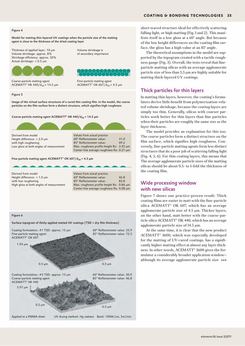
CoAtinG & BonDinG teCHnoLoGies 35
elements36 Issue 3|2011
333
short-waved structure ideal for effectively scattering falling light, or high matting (Fig. 1 and 2). This mani-fests itself in a low gloss at a 60° angle. But because of the low height differences on the coating film sur-face, the gloss has a high value at an 85° angle.
The theoretical assumptions in the model are sup-ported by the topogram created with a tactile rough-ness gauge (Fig. 3). Overall, the tests reveal that fine-particle matting silicas with an average agglomerate particle size of less than 5.5 µm are highly suitable for matting thick-layered UV coatings.
Thick particles for thin layersIn matting thin layers, however, the coating’s formu-lators derive little benefit from polymerization-rela-ted volume shrinkage, because the coating layers are simply too thin. Generally, silicas with coarser par-ticles work better for thin layers than fine particles when their particles are roughly the same size as the layer thickness.
The model provides an explanation for this too: The coarse particles form a distinct structure on the film surface, which signifies high roughness. Con-versely, fine-particle matting agents form less distinct structures that do a poor job of scattering falling light (Fig. 4, 5, 6). For thin coating layers, this means that The average agglomerate particle sizes of the matting silicas should be about 0.5- to 1-fold the thickness of the coating film.
Wide processing window with new silicasFigure 7 shows one practice-proven result: Thick coat ing films are easier to matt with the fine-particle silica ACEMATT® OK 607, which has an average agglomerate particle size of 4.5 µm. Thicker layers, on the other hand, matt better with the coarse-par-ticle silica ACEMATT® HK 440, which has an average agglomerate particle size of 14.5 µm.
At the same time, it is clear that the new product ACEMATT® 3600, which was especially developed for the matting of UV-cured coatings, has a signifi-cantly higher matting effect at almost any layer thick-ness. In other words, ACEMATT® 3600 gives the for-mulator a considerably broader application window— although its average agglomerate particle size
Coarseparticle matting agentACEMATT® HK 440/d50 = 14.5 µm
Fineparticle matting agentACEMATT® OK 607/d50 = 4.5 µm
Figure 5
Image of the virtual surface structures of a cured thin coating film. In the model, the coarse particles on the film surface form a distinct structure, which signifies high roughness
Coarse-particle matting agent ACEMATT® HK 440/d50 = 14.5 µm
Derived from modelHeight difference: > 2.0 µmwith high rougheningLow gloss at both angles of measurement
Fine-particle matting agent ACEMATT® OK 607/d50 = 4.5 µm
Derived from modelHeight difference: < 1.0 µmwith low rougheningHigh gloss at both angles of measurement
Coating formulation: #3 TSD: approx. 15 µm Coarseparticle matting agentACEMATT® HK 440
60° Reflectometer value: 33.985° Reflectometer value: 72.5
60° Reflectometer value: 30.985° Reflectometer value: 46.8
Figure 6
Surface topogram of thinly-applied matted UV coatings (TSD = dry film thickness)
Applied to a PMMA sheet UV drying method: Hg radiator Band: 100W/cm, 5m/min
1.93 µm
5.97 µm
0.5 µm 0.5 µm
0.5 µm0.5 µm
Values from actual practice60° Reflectometer value: 31.085° Reflectometer value: 49.2Max. roughness profile height Rz: 3.92 µmCenterline average roughness Ra: 0.21 µm
Values from actual practice60° Reflectometer value: 46.885° Reflectometer value: 83.8Max. roughness profile height Rz: 0.86 µmCenterline average roughness Ra: 0.08 µm
Figure 4
Model for matting thin-layered UV coatings when the particle size of the matting agent is close to the thickness of the dried coating layer
Thickness of applied layer: 10 µmVolume shrinkage: approx. 8%Shrinkage efficiency: approx. 50%Actual shrinkage: < 0.5 µm
Volume shrinkage is of secondary importance
Coating formulation: #1 TSD: approx. 15 µmFineparticle matting agentACEMATT® OK 607

36 CoAtinG & BonDinG teCHnoLoGies
elements36 Issue 3|2011
deviates only slightly from the fine-particle ACEMATT® OK 607 (Fig. 7).
The technical service engineers used a trick in developing the product: ACEMATT® 3600 is based on a silica that has been aftertreated with polydime-thylsiloxane (PDMS). This aftertreatment not only improves the matting effect but also the rheological properties of the matting agent. This is why it can be added to the coating in higher concentrations.
At the same time, aftertreatment shows that the particle size of the matting agent is not the only in-fluence on the reflectivity of a UV-cured coating. Matting silicas display differences in gloss even among different coating formulations with matting silicas that have the same agglomerate sizes.
The timing of the polymerization process also influences glossThe key factor is the timing of the polymerization process up to the gel point. In this case, “gel point” is defined as the time when the polymerization of the binder has advanced so far that the silica and binder matrix continue shrinking in the same ratio to each other, while the gel point generally is defined as the point where clustering to a macroscopic network begins and the viscosity is increasing significantly.
From the gel point, the agglomerates of the matt-ing agent are fixed in the developing polymer network, and can therefore contribute nothing more to the surface roughness. So the later the gel point occurs, the more pronounced the matting (Fig. 8).
The timing of the gel point depends on a number of factors, such as how fast the molar mass increases and how the segment mobility of the chain molecules or the rheological behavior changes. Consequently, the other components of the formulation also have a significant influence on the mattability of UV-cured coatings: The acrylate oligomers and monomers that polymerize to binders, whereby the monomers in UV-cured coatings also assume the function of the solvent, as well as the photoinitiators.
The number of double bonds plays a key roleAs the studies show, particularly in the example of the oligomers, it is hard to say anything with cer-tainty about mattability: While the relative molar mass, functionality, reactivity, viscosity, and other para meters have an effect on the mattability of the coat ing, the mutual dependencies are varied and complex.
Nevertheless, Evonik has proven that the density of the double bond, which in turn depends on the functionality and the molar mass, plays a key role. This is based on a general rule of thumb: The higher the density of the oligomer double bonds, the better the mattability of the coating. But there is an excep-tion to every rule, and this case is no different. Oligo-
333 Figure 7
Influence of the application weight (proportionate to the layer thickness) and the particle size of the matting agent on the gloss
ACEMATT® OK 607 ACEMATT® 3600 ACEMATT® HK 440
60° Reflectometer value
70
60
50
40
30
20
10
0
Application weight [g/m2]
0 10 20 30 40 50 60 70 80
●
●
Formulations #1, #2 und #3Hg radiator 100 W/cm, 5 m/minDosage: 850 mJ/cm2; Peak: 1,480 mW/cm2
●
●●
●
●
●
●
●
●
●
●
●
●
●
●
●
●
Figure 8
If the gel point is reached too quickly, surface roughening is insufficient (above). Reaching the gel point late provides enough time for sufficient roughening (below)
UV Radiator
Reaction start Gel point Reaction end
Model for insufficient matting Earlier gel point =high shrinkage efficiency =insufficient roughening
Model for effective matting Later gel point = low shrinkage efficiency =sufficiently high roughening
Conveyor speed: 6 m/min = 3 sec exposure
30 cm
●

CoAtinG & BonDinG teCHnoLoGies 37
elements36 Issue 3|2011
mers with low double-bond densities and higher viscos ity are also mattable if the right monomers are used.
The experiments with different monomers have shown that their contribution to matting depends on the shape of the molecule and the conversion rate during polymerization. Monomer molecules with a predominantly linear, chain-like shape promote matt-
Calculation formula for double-bond (DB) density:
333
ing because they have higher mobility and better con-version rates, while three-dimensionally shaped or branched monomers have reduced mobility because of steric hindrance, as well as lower conversion rates, which make them inferior for matting. In the model, a highly branched monomer shrinks with the silica matrix, thereby compromising it and, therefore, the roughness.
DB-Density = Functionality [DB/Mol]
x 1,000 [g/kg Oligomer] = [DB]
Relative molar mass [g/Mol] [kg Oligomer]

38 CoAtinG & BonDinG teCHnoLoGies
elements36 Issue 3|2011
The photoinitiator is another parameter that influ-ences mattability during formulation of the coat ing. “Surface driers”—such as benzophenone with absorp-tion maxima mainly at the short-wave region—that dry the coating film very quickly from the surface down promote gloss, while driers with absorptions in the long-wave range (Fig. 9) promote a significantly more even and prolonged hardening of the coating layer. The gel point, therefore, occurs at a later time—which is desirable.
The actual curing process also provides additional opportunities for reducing the gloss of a coating film. Here, parameters such as the type and emissions spectrum of the light source, intensity and irradiation times, geometry of the radiation source, as well as
the ambient temperature and type of substrate play a role. The technical service engineers at Evonik have investigated these influential factors, too, and have determined their role in influencing the matting grade.
Coatings formulation is still based, above all, on ex-perience and intuition. Evonik’s analyses show that it is, however, possible to coordinate process and formu-lation parameters selectively in such a way as to im-prove control over the matting of UV-cured coatings significantly. Evonik’s experts are, therefore, a giant step closer to their goal of more systematic development of eco-friendly, matt UV coatings. ACEMATT® 3600, the new product that offers processors completely new matting opportunities, is tangible proof.
333
777
[1] Behl, R.; Christian, H.-D.: Radikal matt – zur Mattie rung lösemittelfreier UV-härtender Lacke, Farbe und Lack, Teile 1, 2 + 3, April, Juni und Juli 2011, Vincentz Network
reFerenzen
reinhard Behl completed an appren-ticeship as a chemical laboratory assis-tant at the former Degussa AG, and began working in the application engi-neering department of today’s Inorganic Materials Business Unit at Evonik. Since then, he has performed a variety of functions in the coatings laboratory, where he is currently in charge of matt-ing agents marketed under the ACEMATT® trademark.+49 6181 59-6672 [email protected]
Hans-Dieter Christian studied coatings chemistry at the Niederrhein University of Applied Sciences in Krefeld. Since 1989, he has worked at Evonik, where he has been head of the application engi - n eering department for matting agents, with worldwide responsibility, since 1996.+49 6181 59-4861 [email protected]
Figure 9
Depiction of the absorption curves of various photoinitiators
Benzophenone Bisacylphosphine oxide
Absorption [%]
Benzophenone
O
Bisacylphosphine oxide
O
P
OO
3.0
2.5
2.0
1.5
1.0
0.5
Wavelength [nm]
0
280 300 320 340 360 380 400 420 440 460
Absorption spectrum 0.1% in acetonitrile

neWs 39
elements36 Issue 3|2011
Credits scientific Advisory BoardDr. Norbert FinkeCorporate Innovation Strategy & Management [email protected]
editor in ChiefDr. Karin Aßmann Evonik Services [email protected]
Contribution editorsChrista FriedlMichael Vogel
PhotosEvonik IndustriesKarsten BootmannDieter DeboStefan WildhirtFraunhofer Institute for Process Engineering and Packaging (p. 5)Fotolia/LianeM (p. 6)Getty Images/Cook+Jenshel (p. 13 top)Getty Images/Sot (p. 13 bottom) Fotolia/Electriceye (p. 23 right)Mauritius Images/CuboImages (p. 27)Mauritius Images/Imagebroker/Alfred Schauhuber (p. 28)Fotolia/Broker (p. 31 bottom)IST Metz GmbH, Torsten Becker Illustrationen (p. 32 bottom, 33)Mauritius Images/Age (p. 37)SEA LIFE Deutschland (p. 39)
Design Michael Stahl, Munich (Germany)
Printed by Laupenmühlen Druck GmbH & Co. KG Bochum (Germany)
Reproduction only with permission of the editorial office
Evonik Industries is a worldwide manufacturer of PMMA products sold under the PLEXIGLAS® trademark on the European, Asian, African, and Australian continents and under the ACRYLITE® trademark in the Americas
PublisherEvonik Industries AGCorporate Innovation Strategy & Management
Rellinghauser Straße 1–1145128 EssenGermany
SEA LIFE Speyer: Rare Cuban crocodile admired behind PLEXIGLAS®SEA LIFE Speyer is the only aquarium in Germany that shows Cuban crocodiles. To make this highly endangered reptile species feel as much at home here as in Cuba, SEA LIFE has enlarged the exhibition area by roughly a third. A new habitat has been added to reproduce Cuban swampland, comprising areas of dry land, water that is up to 80 centimeters deep, and a waterfall that pours into the 30,000-liter basin. The whole area is covered with palms and lush vegetation. The water is heated to a temperature of 28°C and an air-conditioning unit keeps the room temperature at about 30°C, with 75 percent atmospheric humidity. A sprinkler unit provides tropical rain.
Six 60-millimeter thick PLEXIGLAS® blocks ensure that visitors can safely admire the three crocodiles that are among the most aggressive of their kind. Despite the high temperature and atmos-pheric humidity, there is no fogging and the glazing provides an
undistorted view of the exotic reptiles. Thanks to the good insulation offered by PLEXIGLAS®, temperatures in the spectator area are pleasant and the sound insulation is good. The pounding of the waterfall can barely be heard.
But these were not the only product properties that convinced the fabricators, Aquarienbau Petermann (Germany), to choose PLEXIGLAS®. Special attention had to be paid to the overall weight of the basin, due to building specifications. The lower weight of acrylic compared to glass, and the good machining and installation options, were also decisive. Evonik’s comprehensive technical service and extensive aquarium know-how enabled the fabricator, who has so far mainly worked with glass constructions, to meet the stringent requirements for glazing the crocodile enclosure, and to give the three Cuban crocodiles a new home.

One contact, many experts.
We love your problems.
For every surface problem we have a solution – the creative power of our people. Evonik’s experts work hand in glove with our customers across all disciplines. That saves time and opens the door to more ideas. The result? Exceptional solutions for exceptional applications.
ww
w.e
voni
k.co
m