ELEG5693 Wireless Communications Ch. 3 Modulation · ELEG5693 Wireless Communications Ch. 3...
62
Department of Electrical Engineering University of Arkansas ELEG5693 Wireless Communications Ch. 3 Modulation Dr. Jingxian Wu [email protected]
Transcript of ELEG5693 Wireless Communications Ch. 3 Modulation · ELEG5693 Wireless Communications Ch. 3...

Department of Electrical EngineeringUniversity of Arkansas
ELEG5693 Wireless Communications
Ch. 3 Modulation
Dr. Jingxian Wu

2
OUTLINE
• Modulation
• Linear Modulation I
• Complex Signal Representation
• Pulse Shaping
• Linear Modulation II
• Non-linear Modulation
• FDMA

3
MODULATION: DEFINITION
• What is modulation?
– The process of modifying a carrier signal (usually a sinusoid) in accordance
with an information-bearing signal (modulating signal), such that the modified
carrier signal (modulated signal) can be used to convey information.
– Carrier signal:
)2sin()( tfAtc cc
• Three parameters: amplitude, frequency, phase
• One or all of them can be modified to carry information.
– E.g. the amplitude is modified to carry information m(t)
)2sin()()( tfAtmts cc
Modulatorm(t) s(t)

4
MODULATION: DEFINITION
• What is modulation? (cont’d)
– Modulating signal m(t)
• Original electrical information-bearing signal
• E.g. electrical waveform representing voice, ASCII, digital video, etc.
• Usually at low frequency
• Also called baseband signal
– Carrier signal c(t)
• High frequency sinusoid to carry the information.
– Modulated signal s(t)
• Carrier signal modified by modulating signal
• At the output of the modulator.
• Also called bandpass signal, or RF signal
Modulator
c(t)
m(t) s(t)
5
MODULATION: WHY?
• Why modulation?
– Shift the frequency of the message signal to the pre-allocated channel.
• For example:
– speech signal: 300 ~ 3100 Hz m(t)
– Shift the signal to the allocated frequency range: 900MHz c(t)
– Transfer the message into a form more suitable for wireless
transmission.
• Limited bandwidth
• Make better use of the limited spectrum
• High frequency signals are more suitable for wireless transmission.
– Enables multiple access
• Signals from different users can be shifted to different frequencies.
• Modulation allows the simultaneous transmission of multiple users.

6
MODULATION: TERMS
• Demodulation
– Recover the original message signal m(t) from the modulated signal s(t).
• Modulator
– Device used to perform modulation
• Demodulator
– Device used to perform demodulation.
Modulator Demodulator
m(t) )(ˆ tm
s(t) r(t)
r(t): modulated signal impaired by fading and noise.

7
MODULATION: CLASSIFICATIONS
• Linear modulation v.s. non-linear modulation
• Analog modulation v.s. Digital modulation
• Amplitude modulation v.s. Angle modulation

8
MODULATION: LINEAR V.S. NON-LINEAR
• Principle of superposition
)()( 21 tmtm
Modulatormi(t) si(t)
– If input is , then output is
– If input is , then output is
• If the input-output of the modulator satisfies principle of
superposition, then the modulator is called linear modulator.
– E.g.
)()( 21 tsts
)(1 tma )(1 tsa
)2sin()()( tfAtmts cc
• If the principle of superposition is not satisfied, the modulator is
non-linear modulator.

9
MODULATION: ANALOG V.S. DIGITAL
• Analog modulation
– m(t) is an analog signal
• m(t) is a continuous function of time t.
• m(t) can take infinite number of values
– Analog modulation is also called continuous-wave (CW) modulation.
– AM radio, FM radio, first generation cell phone system
• Digital modulation
– m(t) is a digital signal
• Take finite number of values
• E.g. {-1, 1}, {-2, -1, 1, 2}, …
– 2nd generation cell phone system
– Digital modulation systems have become more and more popular.

10
MODULATION: AMPLITUDE V.S. ANGLE
• Amplitude modulation
– The amplitude of the carrier, , is modified by the message
signal m(t).
• Angle modulation
– The angle of the carrier is modified by the message signal m(t).
– Frequency modulation: frequency is modified by m(t).
– Phase modulation: phase is modified by m(t)
cA
tft c2)(
11
OUTLINE
• Modulation
• Linear Modulation Techniques I
• Complex Signal Representation
• Pulse Shaping
• Linear Modulation Techniques II
• Non-linear modulation
• FDMA

12
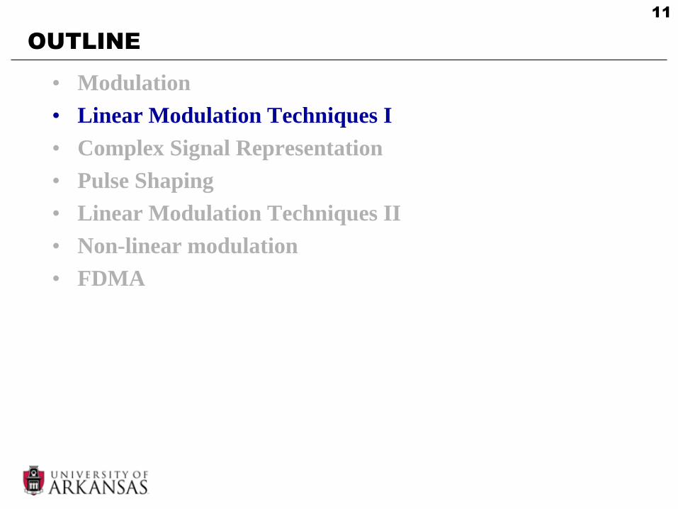
LINEAR MODULATION: AM
• Amplitude modulation (AM)
– The term, AM, is usually used when m(t) is analog
)2cos()()( tftmAts cc
message signalcarrier frequency
• Spectrum of AM
–
–
– S(f) = ?
)(tm )( fM
)2cos( tfA cc )()(2
ccc ffff
A
)(ts
13
LINEAR MODULATION: AM
-W Wf0
M(f)
S(f)
f
cfWfc Wfc cfWfc Wfc
• Center frequency shifted from 0 to
• The bandwidth is doubled from W to 2W
cf
• Spectrum of AM
Baseband signal
bandpass signal
14
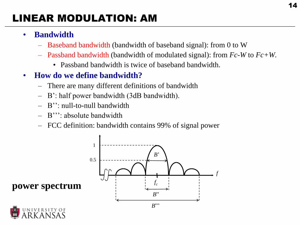
LINEAR MODULATION: AM
• Bandwidth
– Baseband bandwidth (bandwidth of baseband signal): from 0 to W
– Passband bandwidth (bandwidth of modulated signal): from Fc-W to Fc+W.
• Passband bandwidth is twice of baseband bandwidth.
• How do we define bandwidth?
– There are many different definitions of bandwidth
– B’: half power bandwidth (3dB bandwidth).
– B’’: null-to-null bandwidth
– B’’’: absolute bandwidth
– FCC definition: bandwidth contains 99% of signal power
f
B’
fc
B”
1
0.5
B”’
power spectrum

15
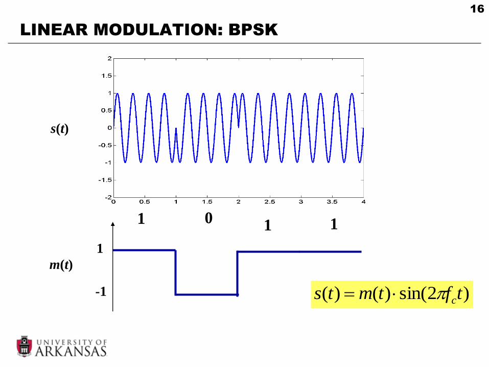
LINEAR MODULATION: BPSK
• Binary phase shift keying (BPSK) Digital modulation
0binary for )2cos(
1binary for )2cos()(
tfA
tfAts
cc
cc
– Or alternatively
0binary for )2cos(
1binary for )2cos()(
tfA
tfAts
cc
cc
– Also called binary amplitude shift keying (BASK)
16
LINEAR MODULATION: BPSK
1 11 0
1
-1
m(t)
s(t)
)2sin()()( tftmts c
17
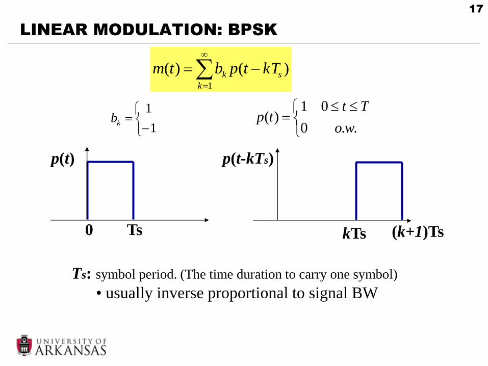
LINEAR MODULATION: BPSK
1
)()(k
sk kTtpbtm
1
1kb
..0
01)(
wo
Tttp
0 Ts
p(t)
(k+1)TskTs
p(t-kTs)
Ts: symbol period. (The time duration to carry one symbol)
• usually inverse proportional to signal BW
18
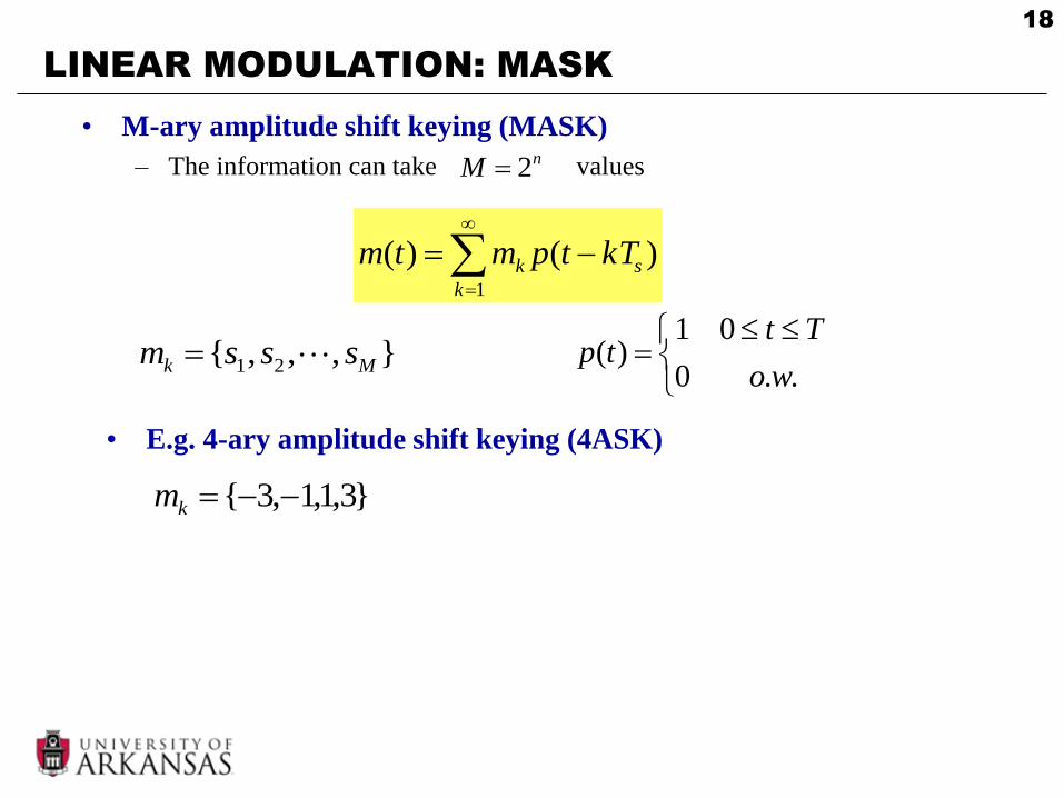
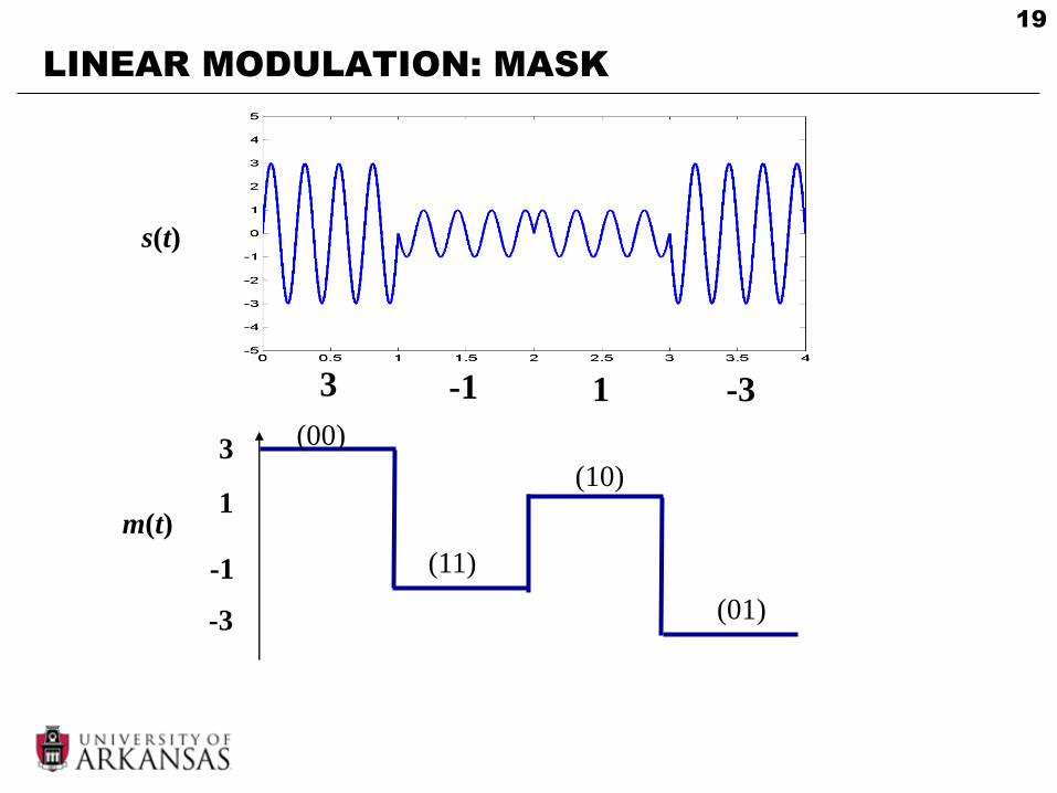
LINEAR MODULATION: MASK
1
)()(k
sk kTtpmtm
},,,{ 21 Mk sssm
..0
01)(
wo
Tttp
• M-ary amplitude shift keying (MASK)
– The information can take values
• E.g. 4-ary amplitude shift keying (4ASK)
}3,1,1,3{ km
nM 2
19
LINEAR MODULATION: MASK
3 -1
1
-1
m(t)
1 -3
3
-3
s(t)
(11)
(10)
(00)
(01)
20
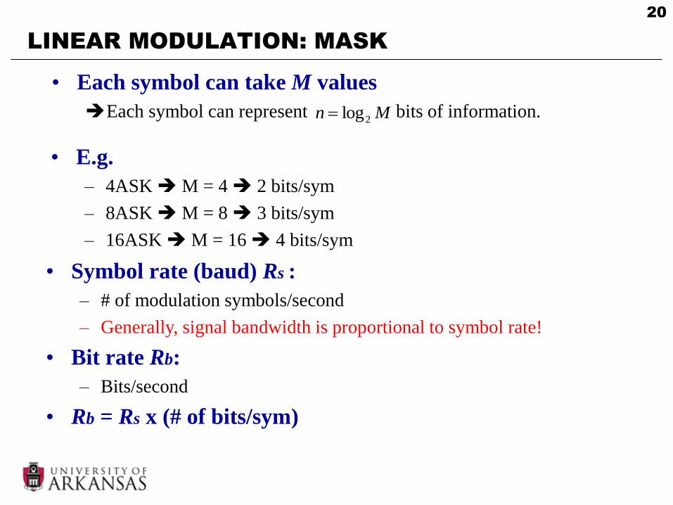
LINEAR MODULATION: MASK
• Each symbol can take M values
Each symbol can represent bits of information. Mn 2log
• E.g.
– 4ASK M = 4 2 bits/sym
– 8ASK M = 8 3 bits/sym
– 16ASK M = 16 4 bits/sym
• Symbol rate (baud) Rs :
– # of modulation symbols/second
– Generally, signal bandwidth is proportional to symbol rate!
• Bit rate Rb:
– Bits/second
• Rb = Rs x (# of bits/sym)

21
LINEAR MODULATION: MASK
• M-ary modulation
– At the same symbol rate, (or fixed bandwidth)
• Larger M more bits/symbol larger bit rate
– M-ary modulation is good for band-limited system
• In wireless systems, spectrum is precious
• M-ary modulation is widely used in wireless systems!
• Typical values used in wireless system: M = 2, 4, 8, 16
• Why don’t we use a very large M?
– If M infinity, then analog signal
– At the same SNR
• Larger M signals are more closed to each other it’s
harder to distinguish between all signals at receiver due to
noise probability of error becomes larger!

22
LINEAR MODULATION: QPSK
• Quadrature phase shift keying (QPSK)
– Combination of two BPSK streams
– Quadrature: orthogonal (two carriers that are 90 degree apart)
)(1 tm
)(2 tm
)2cos( tfA cc
)2sin( tfA cc
)2sin()()2cos()()( 21 tftmAtftmAts cccc
)(ts
Inphase signal quadrature signal
23
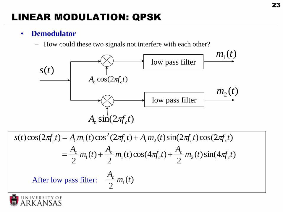
LINEAR MODULATION: QPSK
• Demodulator
– How could these two signals not interfere with each other?
)2cos()2sin()()2(cos)()2cos()( 2
2
1 tftftmAtftmAtfts cccccc
)4sin()(2
)4cos()(2
)(2
211 tftmA
tftmA
tmA
cc
ccc
)(2
1 tmAc
)(1 tm
)(2 tm
)2cos( tfA cc
)2sin( tfA cc
low pass filter
low pass filter
)(ts
After low pass filter:

24
LINEAR MODULATION: QPSK
• At each symbol period, two bits of information are transmitted
– 2 bits/symbol
– Inphase signal has the same bandwidth as BPSK
– Quadrature signal has the same bandwidth as BPSK
– The sum has the same bandwidth as BPSK
• Sum in time domain sum in frequency domain bandwidth
unchanged.
– The same bandwidth as BPSK, but twice the bit rate of BPSK!
– No interference between quadrature and inphase
• Inphase has the same error performance as BPSK
• Quadrature has the same error performance as BPSK
• QPSK has the same error performance of BPSK!
)2cos()()( 1 tftmAts ccI
)2sin()()( 1 tftmAts ccQ
)()()( tststs QI
One of the rare occasions that increase bit rate without sacrificing error performance!
25
OUTLINE
• Modulation
• Linear Modulation Techniques I
• Complex Signal Representation
• Pulse Shaping
• Linear Modulation Techniques II
• Non-linear modulation
• FDMA
26
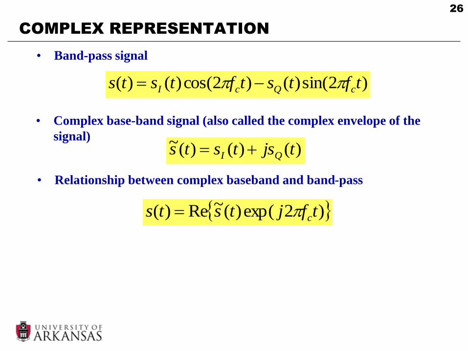
COMPLEX REPRESENTATION
)2sin()()2cos()()( tftstftsts cQcI
• Band-pass signal
• Complex base-band signal (also called the complex envelope of the
signal))()()(~ tjststs QI
• Relationship between complex baseband and band-pass
)2exp()(~Re)( tfjtsts c
27
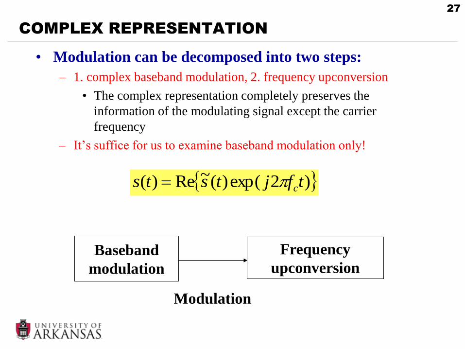
COMPLEX REPRESENTATION
• Modulation can be decomposed into two steps:
– 1. complex baseband modulation, 2. frequency upconversion
• The complex representation completely preserves the
information of the modulating signal except the carrier
frequency
– It’s suffice for us to examine baseband modulation only!
)2exp()(~Re)( tfjtsts c
Baseband
modulation
Frequency
upconversion
Modulation
28
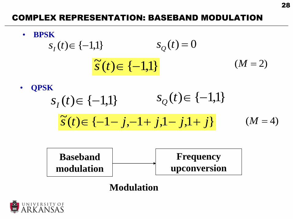
COMPLEX REPRESENTATION: BASEBAND MODULATION
• BPSK
}1,1{)( tsI
0)( tsQ
• QPSK
}1,1{)( tsI
}1,1{)( tsQ
}1,1{)(~ ts
}1,1,1,1{)(~ jjjjts
)2( M
)4( M
Baseband
modulation
Frequency
upconversion
Modulation
29
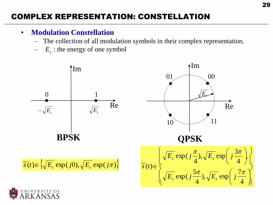
COMPLEX REPRESENTATION: CONSTELLATION
• Modulation Constellation– The collection of all modulation symbols in their complex representation.
– : the energy of one symbol
QPSK
)exp(),0exp()(~ jEjEts ss
4
7exp),
4
5exp(
,4
3exp),
4exp(
)(~
jEjE
jEjE
ts
ss
ss
sE
Re
Im
BPSK
sE sE
0 1
Re
Im
sE
0001
10 11
30
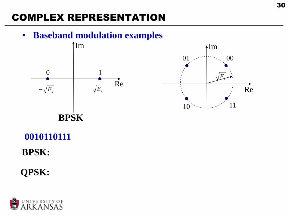
COMPLEX REPRESENTATION
• Baseband modulation examples
Re
Im
BPSK
sE sE
0 1
Re
Im
sE
0001
10 11
0010110111
BPSK:
QPSK:
31
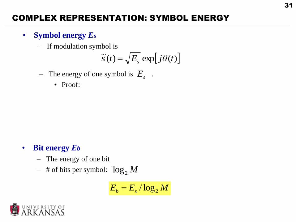
COMPLEX REPRESENTATION: SYMBOL ENERGY
• Symbol energy Es
– If modulation symbol is
)(exp)(~ tjEts s
– The energy of one symbol is .
• Proof:sE
• Bit energy Eb
– The energy of one bit
– # of bits per symbol:
MEE sb 2log/
M2log
32
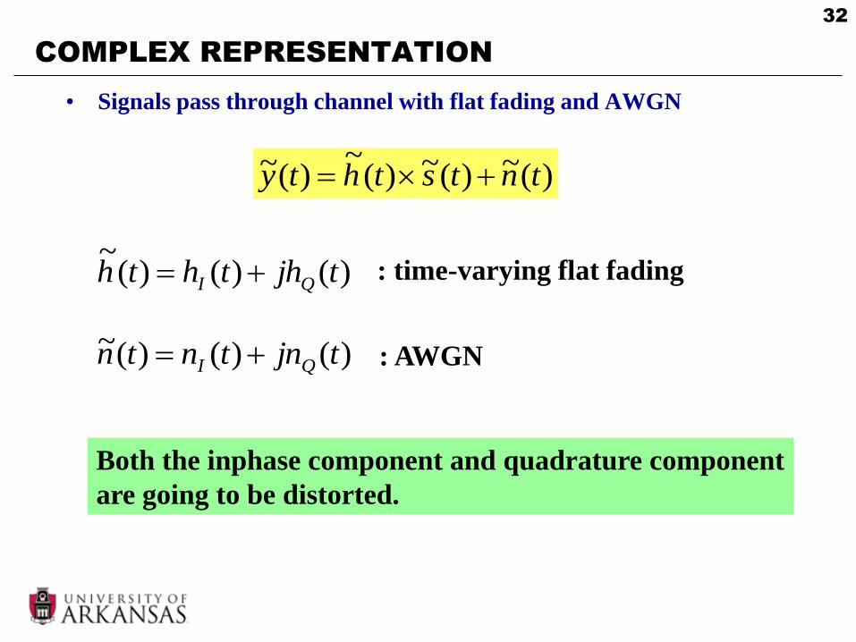
COMPLEX REPRESENTATION
• Signals pass through channel with flat fading and AWGN
)(~)(~)(~
)(~ tntsthty
)()()(~
tjhthth QI : time-varying flat fading
)()()(~ tjntntn QI : AWGN
Both the inphase component and quadrature component
are going to be distorted.
33
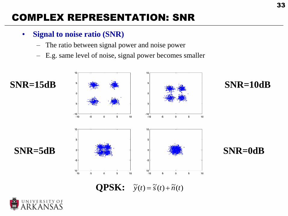
COMPLEX REPRESENTATION: SNR
• Signal to noise ratio (SNR)
– The ratio between signal power and noise power
– E.g. same level of noise, signal power becomes smaller
SNR=15dB SNR=10dB
SNR=5dB SNR=0dB
)(~)(~)(~ tntsty QPSK:
34
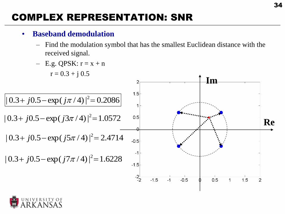
COMPLEX REPRESENTATION: SNR
• Baseband demodulation
– Find the modulation symbol that has the smallest Euclidean distance with the
received signal.
– E.g. QPSK: r = x + n
r = 0.3 + j 0.5
Re
Im
2086.0|)4/exp(5.03.0| 2 jj
0572.1|)4/3exp(5.03.0| 2 jj
4714.2|)4/5exp(5.03.0| 2 jj
6228.1|)4/7exp(5.03.0| 2 jj

35
COMPLEX REPRESENTATION: SNR
• SNR
– The ratio between signal power and noise power
BN
TE
P
PSNR ss
n
s
0
/
Power spectral density of noise Signal bandwidth
Symbol period
B
R
N
E
B
MR
N
E
B
R
N
ESNR bbsbss
0
2
00
log
Symbol rate Rs = 1/Ts Bit rate Rb

36
COMPLEX: BANDWIDTH EFFICIENCY
• Bandwidth efficiency
– How many bits can be accommodated in unit bandwidth (bps/Hz)
B
RbB
bit rate
bandwidth
– Measures the ability of the modulation technique to accommodate data in a
limited bandwidth
• Larger bandwidth efficiency more data can be transferred in limited
bandwidth
• Generally, the bandwidth is proportional to symbol rate
sRB
– For M-ary modulation, fixed bandwidth B fixed symbol rate
• Larger M larger larger bandwidth efficiencysR
MRR sb 2log

37
COMPLEX: ENERGY EFFICIENCY
• Energy efficiency
– At given noise level, how much energy is required to achieve a
certain bit error rate.
– Measured as the value of Eb/N0 required for certain bit error rate
(BER).
• Eb: energy per bit. N0: noise power spectral density.
Eb/N0 (dB)
BER
BER v.s. Eb/N0 is the most important
measure of digital communication systems!
38
OUTLINE
• Modulation
• Linear Modulation Techniques I
• Complex Signal Representation
• Pulse Shaping
• Linear Modulation Techniques II
• Non-linear modulation
• FDMA
39
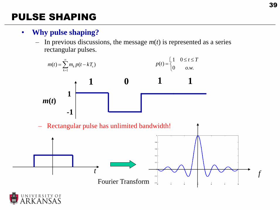
PULSE SHAPING
• Why pulse shaping?
– In previous discussions, the message m(t) is represented as a series rectangular pulses.
1
)()(k
sk kTtpmtm
..0
01)(
wo
Tttp
1 0
1
-1
m(t)
1 1
– Rectangular pulse has unlimited bandwidth!
t fFourier Transform

40
PULSE SHAPING
• Why pulse shaping? (Cont’d)
– Baseband signal has unlimited bandwidth.
– Spectrum of pass-band signal is shifted from baseband signal.
– Thus, pass-band signal has unlimited bandwidth.
– In wireless channel, only limited bandwidth resource is available!
– We want to choose a non-rectangular pulse shape that is limited in
bandwidth!
Baseband
ModulationPulse shaping
Frequency
Upconversion

41
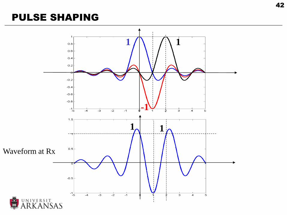
PULSE SHAPING
• Nyquist criterion
– Design the overall response of Tx filter and Rx filter,
such that , and
Tx filter Rx filterChannel
Sampling rate Ts
Continuous time
waveform
Discrete time
samples
1)0( p 1)( snTp 0n– Avoid one symbol interferes with other symbols (Intersymbol interference)
-1
1 1
1)( tpT1)( tpR
)()()( tptptp RT
42
PULSE SHAPING
-1
1 1
Waveform at Rx
1 1
43
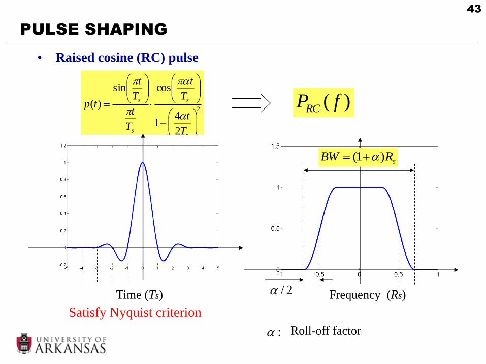
PULSE SHAPING
• Raised cosine (RC) pulse
2
2
41
cossin
)(
s
s
s
s
T
t
T
t
T
t
T
t
tp
Time (Ts) Frequency (Rs)2/
sRBW )1(
)( fPRC
Satisfy Nyquist criterion
: Roll-off factor

44
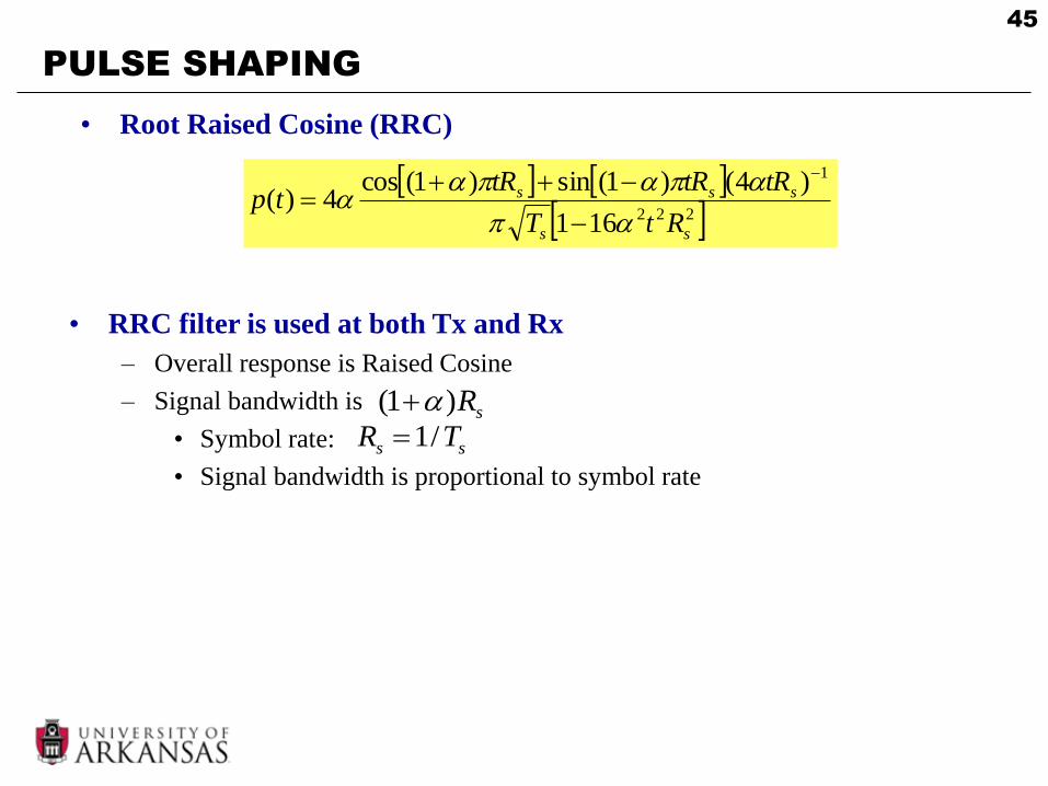
PULSE SHAPING
• Root raised cosine (RRC) pulse
– The frequency domain response of RRC filter is the square root of the
frequency response of RC filter
)()( fPfP RCRRC
Channel)( fPRRC)( fPRRC
– RRC filter has the same bandwidth as RC filter
• The overall response is RC filter
– Satisfy Nyquist criterion
)()()()( fPfPfPfP RCRCRCoverall
)(nx)(ˆ nx
45
PULSE SHAPING
• Root Raised Cosine (RRC)
222
1
161
)4()1(sin)1(cos4)(
ss
sss
RtT
tRtRtRtp
• RRC filter is used at both Tx and Rx
– Overall response is Raised Cosine
– Signal bandwidth is
• Symbol rate:
• Signal bandwidth is proportional to symbol rate
sR)1(
ss TR /1

46
OUTLINE
• Modulation
• Linear Modulation Techniques I
• Complex Signal Representation
• Pulse Shaping
• Linear Modulation Techniques II
• Non-linear modulation
• FDMA

47
LINEAR MODULATION II: 16-QAM
• 16 Quadrature amplitude modulation (16QAM)
– Inphase: 4 amplitude shift keying
– Quadrature: 4 amplitude shift keying
)2sin()()2cos()()( tftstftsts cQcI
}3,1,1,3{)( tsI}3,1,1,3{)( tsQ
)()()(~ tsjtsts QI
• 16-QAM symbols
– Total 4 x 4 = 16 possible combinations.
– M = 16 bits/sym
• Gray mapping
– Two adjacent symbols differ only in 1 bit
– The most common error is that the receiver
decide in favor of the neighbor of the
correct symbol.
• With Gray mapping, only 1 bit error.
4log2 M0010 0110 1110 1010
1011111101110011
0001 0101 1101
1100
1001
100001000000
Im
Re
48
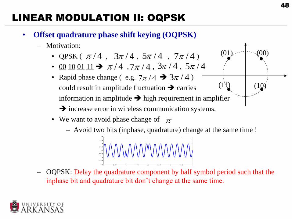
LINEAR MODULATION II: OQPSK
• Offset quadrature phase shift keying (OQPSK)
– Motivation:
• QPSK ( , , , )
• 00 10 01 11 , , ,
• Rapid phase change ( e.g. )
could result in amplitude fluctuation carries
information in amplitude high requirement in amplifier
increase error in wireless communication systems.
• We want to avoid phase change of
– Avoid two bits (inphase, quadrature) change at the same time !
– OQPSK: Delay the quadrature component by half symbol period such that the
inphase bit and quadrature bit don’t change at the same time.
4/
4/7
4/3 4/5 4/7 (00)(01)
(11) (10)4/3
4/ 4/7 4/3 4/5
49
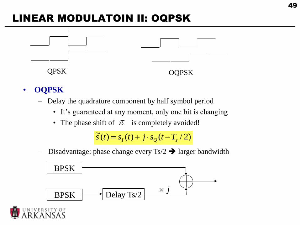
LINEAR MODULATOIN II: OQPSK
• OQPSK
– Delay the quadrature component by half symbol period
• It’s guaranteed at any moment, only one bit is changing
• The phase shift of is completely avoided!
QPSK OQPSK
)2/()()(~sQI Ttsjtsts
BPSK
BPSK Delay Ts/2
– Disadvantage: phase change every Ts/2 larger bandwidth
j
50
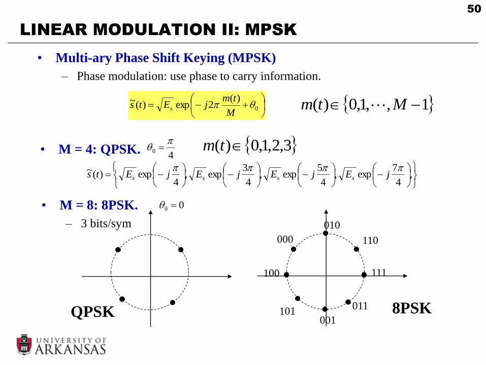
• M = 4: QPSK.
LINEAR MODULATION II: MPSK
• Multi-ary Phase Shift Keying (MPSK)
– Phase modulation: use phase to carry information.
,
4
7exp,
4
5exp,
4
3exp,
4exp)(~
jEjEjEjEts ssss
1,,1,0)( Mtm
• M = 8: 8PSK.
– 3 bits/sym
0
)(2exp)(~
M
tmjEts s
00
QPSK 8PSK
000
001
010
011
100
101
110
111
3,2,1,0)( tm4
0
51
LINEAR MODULATION II: MPSK
• MPSK demodulation
– Find the modulation symbol that has the smallest Euclidean
distance with the received signal.
000
001
010
011
100
101
110
111
8
8
52
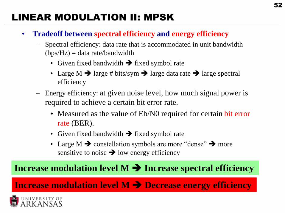
LINEAR MODULATION II: MPSK
• Tradeoff between spectral efficiency and energy efficiency
– Spectral efficiency: data rate that is accommodated in unit bandwidth
(bps/Hz) = data rate/bandwidth
• Given fixed bandwidth fixed symbol rate
• Large M large # bits/sym large data rate large spectral
efficiency
– Energy efficiency: at given noise level, how much signal power is
required to achieve a certain bit error rate.
• Measured as the value of Eb/N0 required for certain bit error
rate (BER).
• Given fixed bandwidth fixed symbol rate
• Large M constellation symbols are more “dense” more
sensitive to noise low energy efficiency
Increase modulation level M Increase spectral efficiency
Increase modulation level M Decrease energy efficiency
53
OUTLINE
• Modulation
• Linear Modulation Techniques I
• Pulse Shaping
• Complex Signal Representation
• Linear Modulation Techniques II
• Non-linear modulation
• FDMA
54
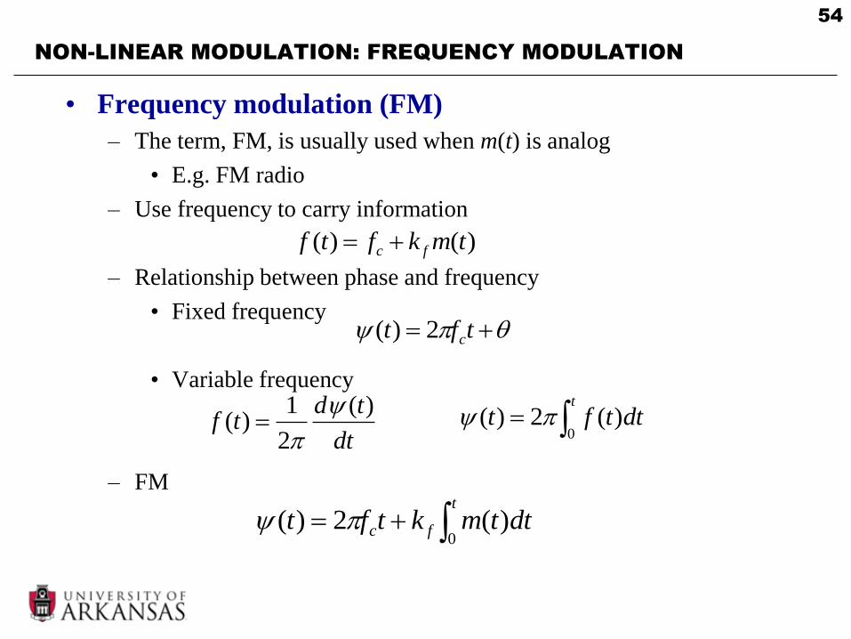
NON-LINEAR MODULATION: FREQUENCY MODULATION
• Frequency modulation (FM)
– The term, FM, is usually used when m(t) is analog
• E.g. FM radio
– Use frequency to carry information
– Relationship between phase and frequency
• Fixed frequency
• Variable frequency
– FM
tft c2)(
dt
tdtf
)(
2
1)(
)()( tmkftf fc
t
dttft0
)(2)(
t
fc dttmktft0
)(2)(

55
NON-LINEAR MODULATION: FREQUENCY MODULATION
• FM
t
fcc dttmktfAts0
)(2cos)(
56
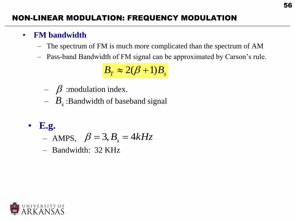
NON-LINEAR MODULATION: FREQUENCY MODULATION
• FM bandwidth
– The spectrum of FM is much more complicated than the spectrum of AM
– Pass-band Bandwidth of FM signal can be approximated by Carson’s rule.
sT BB )1(2
– :modulation index.
– :Bandwidth of baseband signalsB
• E.g.
– AMPS,
– Bandwidth: 32 KHz
kHzBs 4,3

57
NON-LINEAR MODULATION: BFSK
• Binary frequency shift keying (BFSK)
– Constant envelope
1 ,
0 ,
)(2sin
)(2sin)(
tffA
tffAts
cc
cc
0 1 0
If continuous phase (CP)
CP FSK
No abrupt phase change!
58
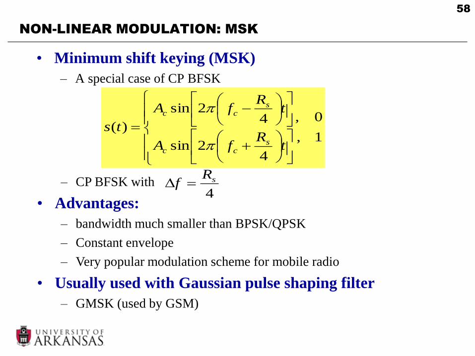
NON-LINEAR MODULATION: MSK
• Minimum shift keying (MSK)
– A special case of CP BFSK
1 ,
0 ,
42sin
42sin
)(
tR
fA
tR
fA
tss
cc
scc
– CP BFSK with
• Advantages:
– bandwidth much smaller than BPSK/QPSK
– Constant envelope
– Very popular modulation scheme for mobile radio
• Usually used with Gaussian pulse shaping filter
– GMSK (used by GSM)
4
sRf

59
NON-LINEAR MODULATION: PRACTICAL ISSUE
• Power amplifier non-linearity
– Power amplifier: amplify signal power before transmission
• To meet the SNR requirement at receiver.
– Amplifier categories: Class A, Class B, Class AB, Class C, Class D
• Class A: linear amplifier
– Signals amplitude at the operational range is amplified linearly.
– The information in amplitude is preserved.
– Should be used for amplitude modulation.
– Requires more transmission power short battery life.
• Class C: non-linear amplifier
– Different amplitude range are amplified by different factors
– The amplitude of the signals is distorted.
– CANNOT be used for amplitude modulated systems. CAN be used for frequency modulated systems.
– Requires less transmission power longer battery life
• From A to B to C to D, linearity becomes worse.

60
OUTLINE
• Modulation
• Linear Modulation Techniques I
• Pulse Shaping
• Complex Signal Representation
• Linear Modulation Techniques II
• Non-linear modulation
• FDMA
61
FDMA
• Frequency division multiple access (FDMA)
– Available spectrum is divided into a set of frequency bands, and each
frequency band is assigned to a user
• FDMA is not FDD
– FDD: frequency division duplex
– The downlink and uplink of one user is using different frequencies.
• Example: AMPS
– FDMA
– Analog voice: FM
– Digital control: BFSK (one frequency for ‘0’, one frequency for ‘1’).
62
FDMA: ACI
• Adjacent Channel Interference (ACI)
– Interference from adjacent channels.
– For some modulations (FM, FSK), the modulated signal has
unlimited bandwidth.
• The signal in one channel will leak into adjacent channels.
• To reduce ACI, introduce some guard bands between adjacent
channels.
– To improve overall bandwidth efficiency, we want to have as
many channel as possible in a limited spectrum.
• Tradeoff between bandwidth efficiency and power efficiency.