ELECTROSTATIC MEMS A THESIS the Requirements for the …
228
A FINITE ELEMENT TEST BED FOR DEVELOPMENT OF FEEDBACK CONTROL LAWS FOR ELECTROSTATIC MEMS by BALASAHEB DNYANDEO KAWADE, B.E. A THESIS IN MECHANICAL ENGINEERING Submitted to the Graduate Faculty of Texas Tech University in Partial Fulfillment of the Requirements for the Degree of MASTER OF SCIENCE IN MECHANICAL ENGINEERING Approved Jordan Berg Chairperson of the Committee Tim Dallas Alexander Idesman Accepted John Borrelli Dean of the Graduate School December, 2005
Transcript of ELECTROSTATIC MEMS A THESIS the Requirements for the …

A FINITE ELEMENT TEST BED FOR DEVELOPMENT OF
FEEDBACK CONTROL LAWS FOR
ELECTROSTATIC MEMS
by
BALASAHEB DNYANDEO KAWADE, B.E.
A THESIS
IN
MECHANICAL ENGINEERING
Submitted to the Graduate Faculty of Texas Tech University in
Partial Fulfillment of the Requirements for
the Degree of
MASTER OF SCIENCE
IN
MECHANICAL ENGINEERING
Approved
Jordan Berg Chairperson of the Committee
Tim Dallas
Alexander Idesman
Accepted
John Borrelli Dean of the Graduate School
December, 2005

ACKNOWLEDGEMENTS
During the course of this project and the research, I have acquired an
impressive indebtedness. It is impossible to acknowledge everyone who has
contributed to this research, but I wish to express my sincere gratitude to several
people in particular. I am thankful to my thesis committee members Dr. Jordan
Berg, Dr. Tim Dallas and Dr. Alexander Idesman for their constant support and
advice throughout this project. My sincere thanks are to Dr. Sanjeeva
Maithriapala whose cooperation in this work cannot be expressed in words.
I thank Dr. Berg for his guidance and willingness to help me in this work.
His motivation in this project not only made it successful but will also be helpful
to my career. The guidance of Dr. Dallas was extremely valuable throughout my
studies in MEMS and research at Texas Tech University. Graduate coursework in
MEMS under guidance of Dr. Dallas was really helpful to start my career in finite
element analysis and the use of ANSYS. Graduate coursework with Dr.
Alexander Idesman was a wonderful opportunity to learn finite element
fundamentals. I am thankful to him for his support to advance my career in FEA.
Financial support provided by Dr. Berg is gratefully acknowledged. I am
extremely grateful to my parents, brother, sister and Mr. Sanjay Zaware, who
gave me an inspiration and strength for my higher studies. I am thankful to Mr.
Ramchandra Deshmukh and Mr. Chirag Bhojani who motivated me for my
higher studies. I am highly indebted to Vijay, Teju, Manish, Amol and other
friends in India who always supported my decesions. Last but not the least, I am
highly indebted to my friends in the Lubbock whom with I shared enjoyable
moments of my life.
ii

To Aai – Dada
iii

CONTENTS
ACKNOWLEDGEMENTS............................................................................................. iii
ABSTRACT .....................................................................................................................vii
LIST OF FIGURES.........................................................................................................viii
CHAPTER
1. INTRODUCTION ........................................................................................................ 1
1.1 Objectives .................................................................................................................4
1.2 Literature Review....................................................................................................5
1.2.1 Pull‐In Analysis And Extending the Travel .................................................5
1.2.2 Modeling and Simulation of Electrostatic MEMS .......................................6
1.3 Outline of Thesis .....................................................................................................7
2. EFFICIENT MULTI‐PHYSICS TRANSIENT ANALYSIS INCORPORATING FEEDBACK DEPENDENT BOUNDARY CONDITIONS * .................................................................................. 8
2.1 Abstract ....................................................................................................................8
2.2 Introduction .............................................................................................................9
2.3 Closed Loop Feedback Control Laws ................................................................12
2.3.1 1‐DOF Piston Microactuator.........................................................................12
2.3.2 2‐DOF Breathing Mode Microactuator .......................................................13
2.4 Procedure ...............................................................................................................14
2.4.1 Integration of Circuit and Electrostatic Analyses......................................14
2.4.2 Runge‐Kutta Adaptive Step Size Integration.............................................16
2.5 Results & Discussion ............................................................................................17
2.6 Conclusion .............................................................................................................24
2.7 References ..............................................................................................................25
3. RESULTS AND DISCUSSION ................................................................................. 28
iv

3.1 Parallel Plate Capacitor ........................................................................................28
3.1.1 Closed Loop Static Feedback Control law..................................................29
3.1.2 Closed Loop Dynamic Feedback Control Law ..........................................32
3.2 Piston Microactuator –With Parasitic Effects....................................................34
3.2.1 Closed Loop Static Feedback Control Law Simulation ............................34
3.2.2 Closed Loop Dynamic Feedback Control Law Simulation......................37
3.3 Breathing Mode Microactuators (2D) ................................................................39
3.3.1 Closed Loop Static Feedback Control Law Simulation ............................40
3.3.2 Closed Loop Dynamic Feedback Control Law Simulation......................44
3.4 Integrated Charge and Position Sensing Auxiliary Electrode........................48
3.5 RF MEMS Switch ..................................................................................................51
3.6 Structural‐thermal‐electrostatic Analysis of a Micromirror ...........................55
4. CONCLUSIONS......................................................................................................... 59
5. FUTURE WORK......................................................................................................... 60
REFERENCES................................................................................................................. 61
APPENDICES
A PREREQUISITES AND SETUP REQUIREMENTS FOR MACROS.................................................................................................................. 67
B APDL MACRO FOR STATIC FEEDBACK CONTROL FOR PISTON MICROACTUATOR...................................................................... 70
C APDL MACRO FOR DYNAMIC FEEDBACK CONTROL FOR PISTON MICROACTUATOR................................................. 85
D APDL MACRO FOR STATIC FEEDBACK CONTROL FOR PISTON MICROACTUATOR WITH PARASITIC EFFECTS................................................................................................................... 93
E APDL MACRO FOR DYNAMIC FEEDBACK CONTROL FOR PISTON MICROACTUATOR WITH PARASITIC EFFECTS .......................................................................................... 106
v

F APDL MACRO FOR STATIC FEEDBACK CONTROL FOR BREATHING MODE MICROACTUATOR............................................. 119
G APDL MACRO FOR DYNAMIC FEEDBACK CONTROL FOR BREATHING MODE MICROACTUATOR............................................................................................. 140
H APDL MACRO FOR STATIC FEEDBACK CONTROL FOR INTEGARTED CHARGE AND POSITION SENSOR.................................................................................................................. 161
I APDL MACRO FOR STATIC FEEDBACK CONTROL FOR RF MEMS SWITCH (BOTH ENDS FIXED BEAM)................................. 174
J JOURNAL AND CONFERENCE PUBLICATIONS WHERE THIS WORK IS UITLIZED .................................................................. 188
vi

ABSTRACT
This project presents the ANSYS simulation techniques for an
electrostatically‐actuated MEMS device incorporating feedback control laws. The
electrostatic MEMS device consists of a movable electrode, suspended on
flexible, elastic structures, and one or more fixed drive electrodes. Nonlinear
feedback control laws are simulated in ANSYS multi‐physics solver and a
transducer element. ANSYS multi‐physics solver is limited for these types of
simulations. ANSYS doesn’t support multiframe restart and the combined circuit
and electrostatic analysis are incompatible. This work presents simulation
techniques based on numerical methods to circumvent these limitations. The
proposed technique eliminates the circuit elements from the model, and instead
propagates the associated states in an APDL macro. ANSYS auto time stepping
method is not applicable for closed‐loop feedback control systems because loads
are calculated at each step based on simulation output at the previous step. An
adaptive step size Runge‐Kutta integration routine is incorporated within APDL
macro to develop an efficient simulation technique. The simulation efficiency of
the static closed loop feedback control systems is increased by a factor more than
100. However, a dynamic closed loop feedback control systems exhibits only a
brief initial transient, and then does not permit further step size increases. To
increase the simulation efficiency of such systems, the adaptation logic is turned
off once the step size stabilizes. Simulation results for representative MEMS
devices including a one‐DOF piston microactuator and a two‐DOF
rotating/translating microactuator demonstrate the efficiency of these simulation
techniques.
vii
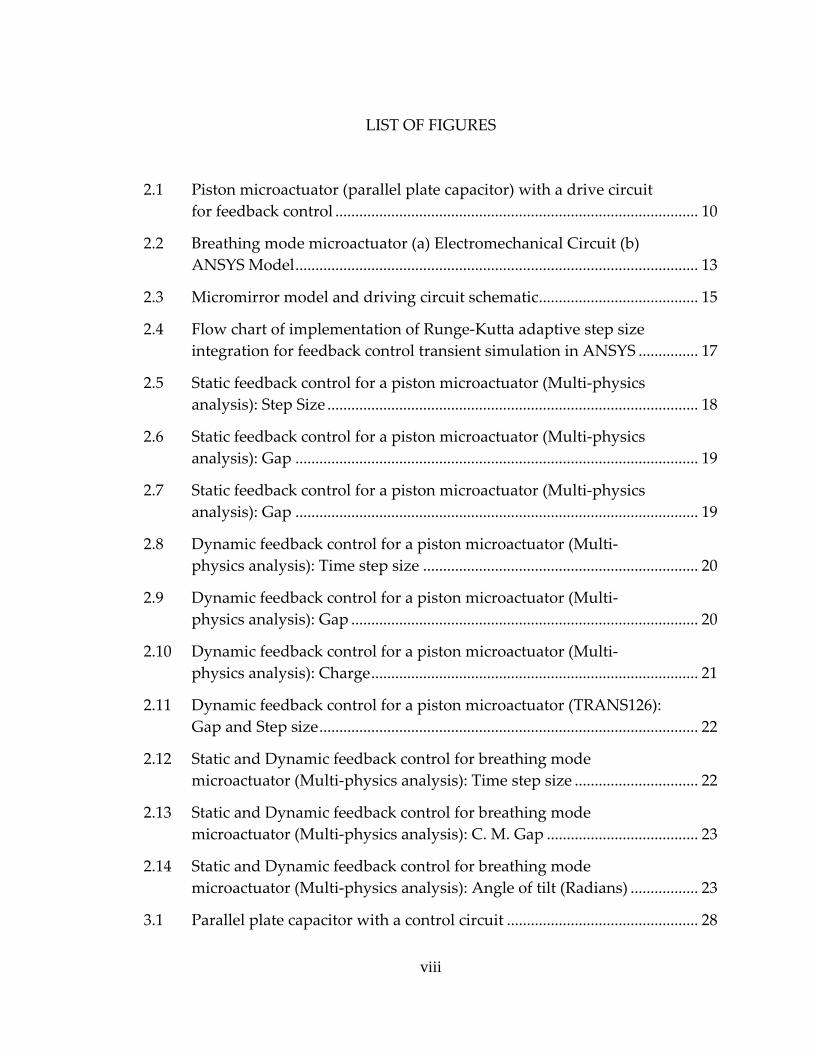
LIST OF FIGURES
2.1 Piston microactuator (parallel plate capacitor) with a drive circuit for feedback control ........................................................................................... 10
2.2 Breathing mode microactuator (a) Electromechanical Circuit (b) ANSYS Model..................................................................................................... 13
2.3 Micromirror model and driving circuit schematic........................................ 15
2.4 Flow chart of implementation of Runge‐Kutta adaptive step size integration for feedback control transient simulation in ANSYS ............... 17
2.5 Static feedback control for a piston microactuator (Multi‐physics analysis): Step Size ............................................................................................. 18
2.6 Static feedback control for a piston microactuator (Multi‐physics analysis): Gap ..................................................................................................... 19
2.7 Static feedback control for a piston microactuator (Multi‐physics analysis): Gap ..................................................................................................... 19
2.8 Dynamic feedback control for a piston microactuator (Multi‐physics analysis): Time step size ..................................................................... 20
2.9 Dynamic feedback control for a piston microactuator (Multi‐physics analysis): Gap ....................................................................................... 20
2.10 Dynamic feedback control for a piston microactuator (Multi‐physics analysis): Charge.................................................................................. 21
2.11 Dynamic feedback control for a piston microactuator (TRANS126): Gap and Step size............................................................................................... 22
2.12 Static and Dynamic feedback control for breathing mode microactuator (Multi‐physics analysis): Time step size ............................... 22
2.13 Static and Dynamic feedback control for breathing mode microactuator (Multi‐physics analysis): C. M. Gap ...................................... 23
2.14 Static and Dynamic feedback control for breathing mode microactuator (Multi‐physics analysis): Angle of tilt (Radians) ................. 23
3.1 Parallel plate capacitor with a control circuit ................................................ 28
viii

3.2 Static feedback control law simulation for the parallel plate capacitor. (a) Time Step Size vs Time (b) Gap vs Time ................................ 30
3.3 Static feedback control law simulation for the parallel plate capacitor. (a) Control Voltage vs Time (b) Charge vs Time......................... 31
3.4 Dynamic feedback control law simulation for the parallel plate capacitor, Gap vs Time...................................................................................... 32
3.5 Dynamic feedback control law simulation for the parallel plate capacitor (a) Control Voltage vs Time (b) Charge vs Time.......................... 33
3.6 Parallel plate capacitor with a parasitic conductor and a control circuit ................................................................................................................... 34
3.7 Static feedback control law simulation for a parallel plate capacitor with a parasitic conductor. (a) Time step size vs Time (b) Gap vs Time ..................................................................................................................... 35
3.8 Static feedback control law simulation for a parallel plate capacitor with a parasitic conductor. (a) Voltages vs Time (b) Charges vs Time ..................................................................................................................... 36
3.9 Dynamic feedback control law simulation for a parallel plate capacitor with a parasitic conductor, Time step Size vs Time..................... 37
3.10 Dynamic feedback control law simulation for the parallel plate capacitor with a parasitic conductor. (a) Gap vs Time (b) Voltages vs Time ................................................................................................................ 38
3.11 Dynamic feedback control law simulation for the parallel plate capacitor with a parasitic conductor, Charges vs Time................................ 39
3.12 Breathing mode microactuator. (a) Schematic digram of a microactuator with control circuits (b) ANSYS model................................. 40
3.13 Static feedback control law simulation for the breathing mode microactuator – Deformed configuration....................................................... 41
3.14 Static feedback control law simulation for the breathing mode microactuator. (a) Time Step Size vs Time (b) C. G. Gap vs Time.............. 42
3.15 Static feedback control law simulation for the breathing mode microactuator. (a) Angle of tilt vs Time (b) Control Voltage (U1) vs Time ..................................................................................................................... 43
ix

3.16 Static feedback control law simulation for the breathing mode microactuator – Charge (Q1) vs Time............................................................. 44
3.17 Dynamic feedback control law simulation for the breathing mode microactuator – Deformed configuration....................................................... 45
3.18 Dynamic feedback control law simulation for the breathing mode microactuator. (a) Time Step Size vs Time (b) C. G. Gap vs Time.............. 46
3.19 Dynamic feedback control law simulation for the breathing mode microactuator. (a) Angle of tilt vs Time (b) Control Voltage (U1) vs Time ..................................................................................................................... 47
3.20 Dynamic feedback control law simulation for the breathing mode microactuator – Charge (Q1) vs Time............................................................. 48
3.21 Integrated charge and position sensor. (a) Schematic diagram of the sensor with a control circuit (b) Outline of the ANSYS model ................... 49
3.22 Static feedback control law simulation for the integrated charge and position sensor. (a) Gap vs Time (b) Control Voltage vs Time ................... 50
3.23 Static feedback control law simulation for the integrated charge and position sensor – Charge vs Time.................................................................... 51
3.24 Both ends fixed RF MEMS Switch (a) ANSYS model (b) Deformed configuration....................................................................................................... 52
3.25 Static feedback control law simulation for the both ends fixed RF MEMS Switch. (a) Time Step Size vs Time (b) Gap vs Time ....................... 53
3.26 Static feedback control law simulation for the both ends fixed RF MEMS Switch. (a) Control Voltage vs Time (b) Charge vs Time................ 54
3.27 The micromirror fabricated at the Maddox laboratory at TTU (a) SEM image ‐ undeformed state (b) NT1100 LCD image ‐ deformed state ...................................................................................................................... 56
3.28 Finite element analysis of the micromirror ‐ deformed configuration (a) at 25 volts (b) at 26 volts ..................................................... 57
3.29 Interferometric profile for the deformed micromirror (a) at 0 volts (b) at 17 volts....................................................................................................... 58
x

CHAPTER I
1. INTRODUCTION
Micro Electro Mechanical Systems (MEMS), Micro Opto Electro
Mechanical Systems (MOEMS) and Nano Electro Mechanical Systems (NEMS)
are evolving fields. These devices are comprised of miniature parts and operate
at micro and nano levels. The actuation technique for them may include
piezoelectric, electrostatic, thermal, shape memory alloys or magnetic actuation.
Among these devices, electrostatic devices are most widely used. What makes
them so popular? The answer is their simplicity, flexibility of operation and that
they can be fabricated using standard microelectronics fabrication processes and
materials. They are superior to traditional devices because of low power
requirements, low losses and low costs. Their actuation may be analog or digital.
Digital devices have only two possible configurations whereas analog devices
can operate in many configurations. Electrostatic actuators are widely used in the
following: micromirrors in optical switching, RF MEMS switches used in
wireless telecommunication, pressure sensors, spatial light modulators,
microgrippers [5, 7], highly sensitive electrometers and electrostatic fieldmeters
[33], RF filters, phase shifters and RF antennas [47]. Direct contact type switches
and capacitively coupled switches are widely used. Direct contact switches fail
mainly because of surface damage with repetitive contact [8]. Anti‐Stiction
measures needs to be implemented to overcome stiction problem. In contrast to
these direct contact switches, capacitively coupled switches minimize metal to
metal contact and make use of the well‐known pull‐in phenomenon. An
electrostatic actuation is initiated because of coulomb forces which are developed
1
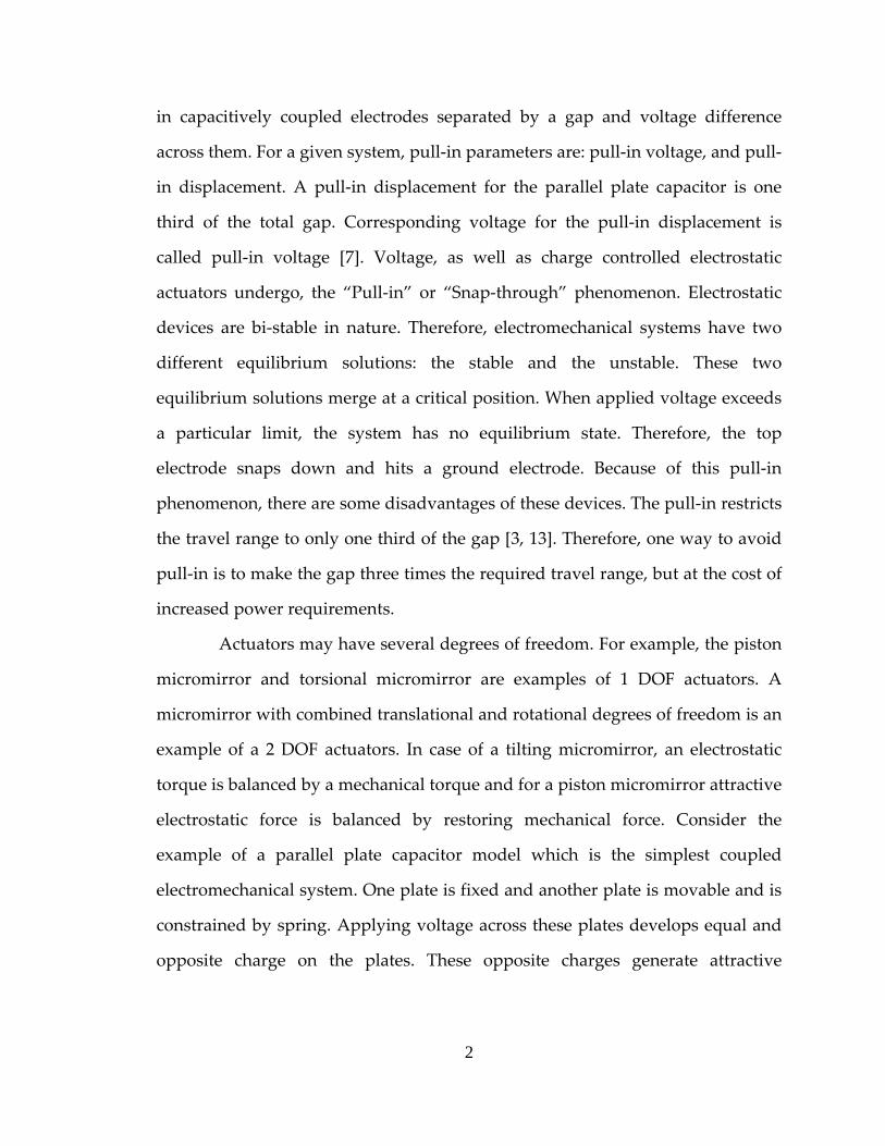
in capacitively coupled electrodes separated by a gap and voltage difference
across them. For a given system, pull‐in parameters are: pull‐in voltage, and pull‐
in displacement. A pull‐in displacement for the parallel plate capacitor is one
third of the total gap. Corresponding voltage for the pull‐in displacement is
called pull‐in voltage [7]. Voltage, as well as charge controlled electrostatic
actuators undergo, the “Pull‐in” or “Snap‐through” phenomenon. Electrostatic
devices are bi‐stable in nature. Therefore, electromechanical systems have two
different equilibrium solutions: the stable and the unstable. These two
equilibrium solutions merge at a critical position. When applied voltage exceeds
a particular limit, the system has no equilibrium state. Therefore, the top
electrode snaps down and hits a ground electrode. Because of this pull‐in
phenomenon, there are some disadvantages of these devices. The pull‐in restricts
the travel range to only one third of the gap [3, 13]. Therefore, one way to avoid
pull‐in is to make the gap three times the required travel range, but at the cost of
increased power requirements.
Actuators may have several degrees of freedom. For example, the piston
micromirror and torsional micromirror are examples of 1 DOF actuators. A
micromirror with combined translational and rotational degrees of freedom is an
example of a 2 DOF actuators. In case of a tilting micromirror, an electrostatic
torque is balanced by a mechanical torque and for a piston micromirror attractive
electrostatic force is balanced by restoring mechanical force. Consider the
example of a parallel plate capacitor model which is the simplest coupled
electromechanical system. One plate is fixed and another plate is movable and is
constrained by spring. Applying voltage across these plates develops equal and
opposite charge on the plates. These opposite charges generate attractive
2
electrostatic forces causing the movable plate to move toward the fixed plate. As
the plate moves, electrostatic forces which are directly proportional to the inverse
of the gap between parallel plates changes. The mechanical restoring force is a
linear function of the plate displacement. Finally the plate settles at an
equilibrium position. If the applied voltage is greater than this critical pull‐in
voltage, the movable plate snaps down to the fixed electrode. If pull‐in is
eliminated, the entire gap can be utilized. It will extend tunable range of the
optical devices. Recently researchers came up with different control schemes and
are discussed in details in the literature review.
Now we have numerous simulation tools [45]. Simulink is a widely used
simulation toolbox provided by Matlab. Spice is used to simulate electronic
circuits but can also simulate features of other fields. Both of these are system
level simulation tools. VisSim and Saber are also system level simulation tools.
Finite Element Analysis (FEA) is well suited to MEMS applications. We can do
all types of analysis like static, transient, dynamic and modal. CoventorWare,
IntelliSuite (Specifically developed for MEMS), ANSYS, ABAQUS are FEA based
simulation software. Because of geometric nonlinearity, large deflections,
fringing fields, electrode contact, and non‐uniform charge distribution, modeling
and simulation of coupled electromechanical systems is challenging. Finite
element analysis can be used to account for all of these characteristics. Extracting
pull‐in parameters of complex models and analyzing their dynamic behavior is
possible through these packages. Simulations tool help us to predict model
performance before it is built. Based on simulation results, we can optimize
design parameters. MEMS simulation is much more complicated because
multiple fields such as mechanical, electrical, chemical, magnetic, thermal, and
3

fluidic may interact with each other. Depending on complexity of the model and
the type of the analysis, these analyses may become computationally expensive.
Therefore, development of efficient simulation techniques are important research
topics.
1.1 Objectives
As discussed in the introduction, the stable operating range of electrostatic
MEMS devices is limited to one third of the initial gap. The finite element
software package ANSYS is used to simulate time transient behavior of coupled
electromechanical devices. This work concentrates on development of closed
loop feedback control laws. The multifield solver is used to model coupling
between structural and the electrostatic domain. The multifield solver has
limitation on time step selection. ANSYS prohibits the coupling of circuit and
electrostatic analysis. These analyses will be combined in a single analysis
without using circuit elements. The limitation of the multifield solver is that it
doesn’t support multiframe restart and it doesn’t support remeshing. To
overcome these limitations and increase computational efficiency, Runge‐Kutta
adaptive step size integration is implemented in ANSYS. Some coupled
electromechanical devices such as both‐ends‐fixed beam (RF MEMS switch),
parallel plate capacitor (piston microactuator), deformable micromirror with
combined translation and rotation and torsional micromirror (TI DMD) are used
to simulate nonlinear feedback control laws.
4

1.2 Literature Review
Recently, electrostatic pull‐in analyses, extraction of pull‐in parameters,
extending travel range of electrostatic microactuators, and simplification of
coupled electromechanical systems have acquired greater attention of
researchers.
1.2.1 Pull‐In Analysis And Extending the Travel
Studies of the pull‐in phenomenon and pull‐in parameters for parallel
plate capacitors and torsional microactuators can be found in [7, 17, 28, 39, 44].
Joachim Haase [13] studied turning points in electromechanical systems and
determination of pull‐in parameters. They found that pull‐in parameters are
associated with these turning points of the solution curve. There are other
sources like symmetric drive, asymmetric drive, and temperature which affects
pull‐in parameters [20]. With growing applications, MEMS systems are becoming
more and more complex. In this context, study of electrostatic actuators with
multiple voltage sources is very important. Elata et al. [35] and Chiou and Lin
[40] developed a generalized analytical method to study such a system. They
found that pull‐in features of multiple driving electrodes system are much
different than those of single driving electrodes. Several control schemes are
developed [6, 8, 11, 14, 15, 16, 18, 19, 21, 22, 38] which includes constant‐charge
(CC) and constant‐voltage (CV) biasing, series capacitor feedback, switched‐
capacitor circuit and fixed capacitor control scheme. Other control schemes
incorporated leverage bending [25], differential voltage operation [26] and
several varieties of approaches [24, 30, 32, 42]. Maithripala et al. [37, 46]
developed nonlinear static and dynamic output feedback stabilization schemes
5
[1, 2, 3, 4, 5]. With dynamic output feedback stabilization, it is possible to achieve
full gap operation and improved transient performance.
1.2.2 Modeling and Simulation of Electrostatic MEMS
Researchers developed parametric models to predict performance of
coupled electromechanical devices and to avoid heavy finite element calculation
[9, 10, 12, 31, 36]. MEMS models sometimes are computationally inefficient,
especially transient analyses. Therefore, a topic of the current research is to
develop macromodels, i.e. reduced order models which can accurately describe
device performance [4, 5, 23, 27]. Reduced order macromodels have the
advantage that they can predict device performance locally and globally.
Simplified methods of electrostatic analysis using a Lagrangian approach is done
by [29]. As the movable conductor moves or deforms, the electrostatic field is
altered and normally its deformed geometry needs to be recalculated for further
analysis. But with their simplified Lagrangian approach, undeformed mesh of
electrostatic analysis can be used for calculation of charge distribution. Voltage
Iteration (VI) is traditional scheme to extract pull‐in parameters. In the VI
scheme, voltage is continuously increased and the system is solved till
convergence. Therefore, in the VI scheme, voltage at which the system doesn’t
converge is considered as pull‐in voltage. Obviously, as the system approaches
the pull‐in state, the number of iterations required increases. Bochobza‐Degani et
al. [43] developed an efficient Displacement Iteration Pull‐In Extraction (DIPIE),
which is a fast and efficient scheme for extracting of pull‐in parameters. They
start with an inverse technique. In contrast to conventional techniques where the
electrostatic system is solved first and then the structural domain, they assigned
6

some displacement to a pre‐chosen point and solved for the structural field. This
generates the reaction force at the selected point. Then they go for solving the
electrostatic field where they apply the voltage boundary condition and also
modify the reaction force. The voltage is continuously increased until the
reaction force at the selected point disappears. The convergence rate they
achieved with DIPIE is much faster than traditional VI scheme. More than that,
DIPIE definitely converged at pull‐in whereas VI scheme never converged at
pull‐in. Xingtao Wu et al. [27] formulate a generalized capacitance based model
of electromechanical system which eliminates traditional force based calculation
approach.
1.3 Outline of Thesis
The general outline of this thesis is as follows:
Chapter II is the conference paper to be presented at the ANSYS User’s
conference. The paper highlights the simulation strategies. It describes the
electrostatic and circuit analysis integration and implementation of adaptive step
Runge‐Kutta step size integration for the coupled field analysis.
Chapter III is a discussion of simulation results of various representative
electrostatic microactuators. Simulation results of piston microactuator (1‐DOF),
breathing mode microactuator (2‐DOF), RF MEMS switch, integrated charge and
position sensor, parasitic effects for a piston microactuator are presented.
Chapter IV is the conclusion section, which summarizes the results and
achievements of this project.
Chapter V suggests the possible advances in this work for future studies.
7
CHAPTER II
2. EFFICIENT MULTI‐PHYSICS TRANSIENT
ANALYSIS INCORPORATING FEEDBACK
DEPENDENT BOUNDARY CONDITIONS *
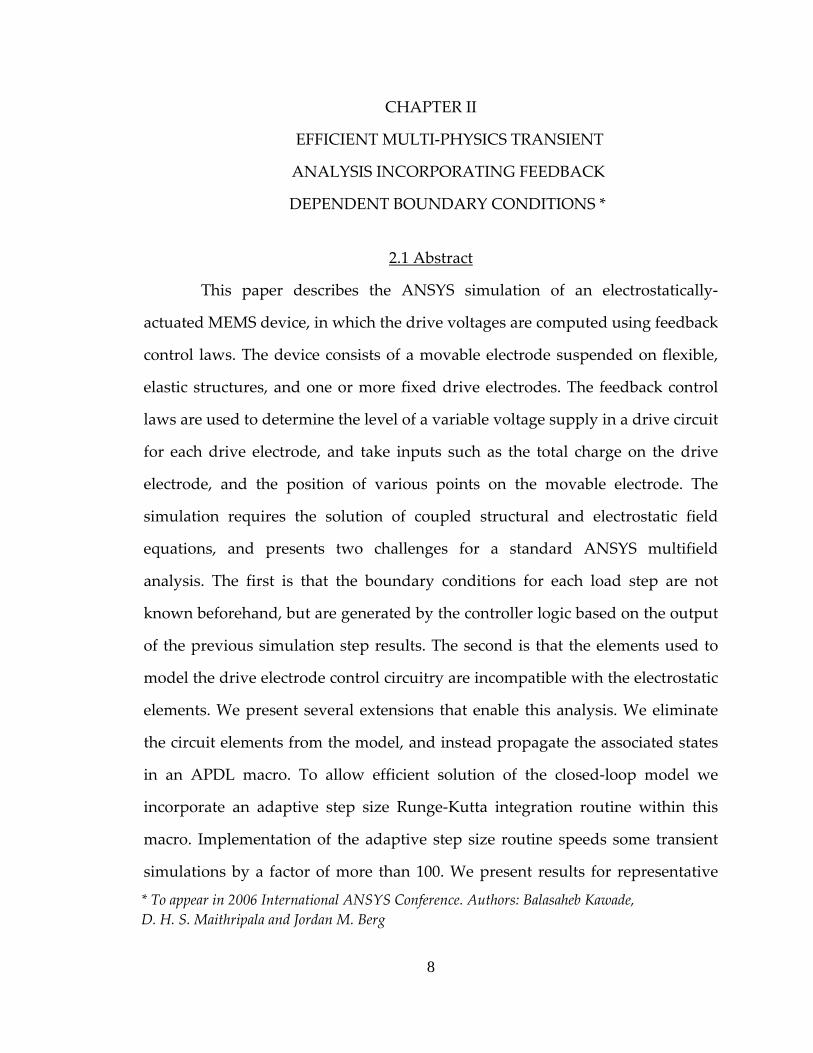
2.1 Abstract
This paper describes the ANSYS simulation of an electrostatically‐
actuated MEMS device, in which the drive voltages are computed using feedback
control laws. The device consists of a movable electrode suspended on flexible,
elastic structures, and one or more fixed drive electrodes. The feedback control
laws are used to determine the level of a variable voltage supply in a drive circuit
for each drive electrode, and take inputs such as the total charge on the drive
electrode, and the position of various points on the movable electrode. The
simulation requires the solution of coupled structural and electrostatic field
equations, and presents two challenges for a standard ANSYS multifield
analysis. The first is that the boundary conditions for each load step are not
known beforehand, but are generated by the controller logic based on the output
of the previous simulation step results. The second is that the elements used to
model the drive electrode control circuitry are incompatible with the electrostatic
elements. We present several extensions that enable this analysis. We eliminate
the circuit elements from the model, and instead propagate the associated states
in an APDL macro. To allow efficient solution of the closed‐loop model we
incorporate an adaptive step size Runge‐Kutta integration routine within this
macro. Implementation of the adaptive step size routine speeds some transient
simulations by a factor of more than 100. We present results for representative
* To appear in 2006 International ANSYS Conference. Authors: Balasaheb Kawade, D. H. S. Maithripala and Jordan M. Berg
8

MEMS devices including a one‐DOF piston microactuator and a two‐DOF
rotating/translating microactuator.
2.2 Introduction
Finite element analysis (FEA) is a powerful analysis tool, but it can be
computationally demanding for complex physics and model geometries. The
simulation of microelectromechanical systems (MEMS) often involves features
such as coupling between multiple physics domains, large deflections, and
contact, and presents many challenges to FEA. Thus, efficient FEA simulation
techniques for MEMS analysis are an active research topic [9, 10, 11, 12]. The
current paper considers electrostatically‐actuated MEMS, and neglects effects
such as squeeze‐film damping. The ANSYS FEA software package contains semi‐
automated tools for simulation of such systems, including the multi‐physics
solver, the ESSOLV macro, and the ROM144, TRANS126, and TRANS109
elements. Each tool has specific strengths, but none is without problems. The
multi‐physics solver enables integration of multiple fields in a single analysis.
However, neither non‐structural analysis nor the multi‐physics solver support
multiframe restarts. Further, the multifield solver constrains the end time of a
load step to be an integer multiple of the current step size. Automatic remeshing,
which replaces the distorted mesh of a non‐structral field with a quality mesh, is
not available for the multiphysics and ROM analysis as of ANSYS release 10.0
[13]. Despite these problems, the multi‐physics solver is the most powerful,
flexible, and general approach to MEMS analysis available in ANSYS.
Electrostatic actuation is a widely used actuation technique that exploits
the attractive Coulomb forces that arise between capacitively coupled electrodes.
9

A simple electrostatically‐actuated MEMS is shown schematically in Fig. 2.1.
Such a system will exhibit the well‐known nonlinear bifurcation phenomenon
called “pull‐in.” When the pull‐in voltage is exceeded, no equilibrium points
exist for the movable electrode, which will be drawn to the static electrode [16].
In its simplest form, pull‐in restricts the stable operating range of parallel plate
electrostatic devices to one‐third of the zero voltage capacitive gap. Several
control strategies have been proposed or implemented to extend this operating
range [6, 7, 8, 15, 17]. The feedback control laws presented in [1, 3, 4, 5] have been
developed for several microactuator configurations. Implementation issues are
discussed in [2]. The present paper describes the ANSYS validation of these
control laws. ANSYS simulation can incorporate effects such as geometric
nonlinearities, large deflections, fringing fields, electrode coupling, and non‐
uniform charge distribution that are usually neglected in an analytical treatment.
Figure 1.1: Piston microactuator (parallel plate capacitor) with a drive circuit for feedback control
While the MEMS device itself is modeled using structural and
electrostatic elements, it is controlled through a drive circuit, as shown in Fig. 3.3.
Circuit and electrostatic elements in ANSYS both have a voltage degree of
10

freedom, but with different associated reaction forces—current and charge,
respectively. Therefore, these elements cannot be combined in a single analysis
[13]. The TRANS126 transducer element is compatible with discrete circuit
elements, but ignores fringing fields and is not well‐suited to cases where those
fields are significant. In order to handle more general situations, and to use
electrostatic and structural elements with the multi‐field solver in conjunction
with a discrete driving circuit, we propagate the circuit states externally to the
FEA analysis, using a macro written in the ANSYS Parametric Design Language
(APDL). The closed‐loop control algorithm varies electrode voltages to control
the position of the movable electrode. The voltages are determined based on
measured voltages, positions, and velocities. Thus the boundary conditions at a
particular time are not known in advance, but must be calculated and applied at
that time step. This means that the stepsize controls incorporated in the ANSYS
package cannot be applied. However fixed stepsize integration is typically
extremely inefficient. Thus, an adaptive stepsize Runge‐Kutta integration scheme
is incorporated into the APDL executive macro.
Finally, the results of simulation of several benchmark control problems
are described. The adaptive stepsize routine is seen to improve performance by a
factor of more than 100. Simulation of both static and dynamic output feedback
control laws are demonstrated on a piston microactuator and a breathing‐mode
micromirror. The dynamic output feedback case is computationally demanding,
but due to the implementation features discussed it is tractable.
11
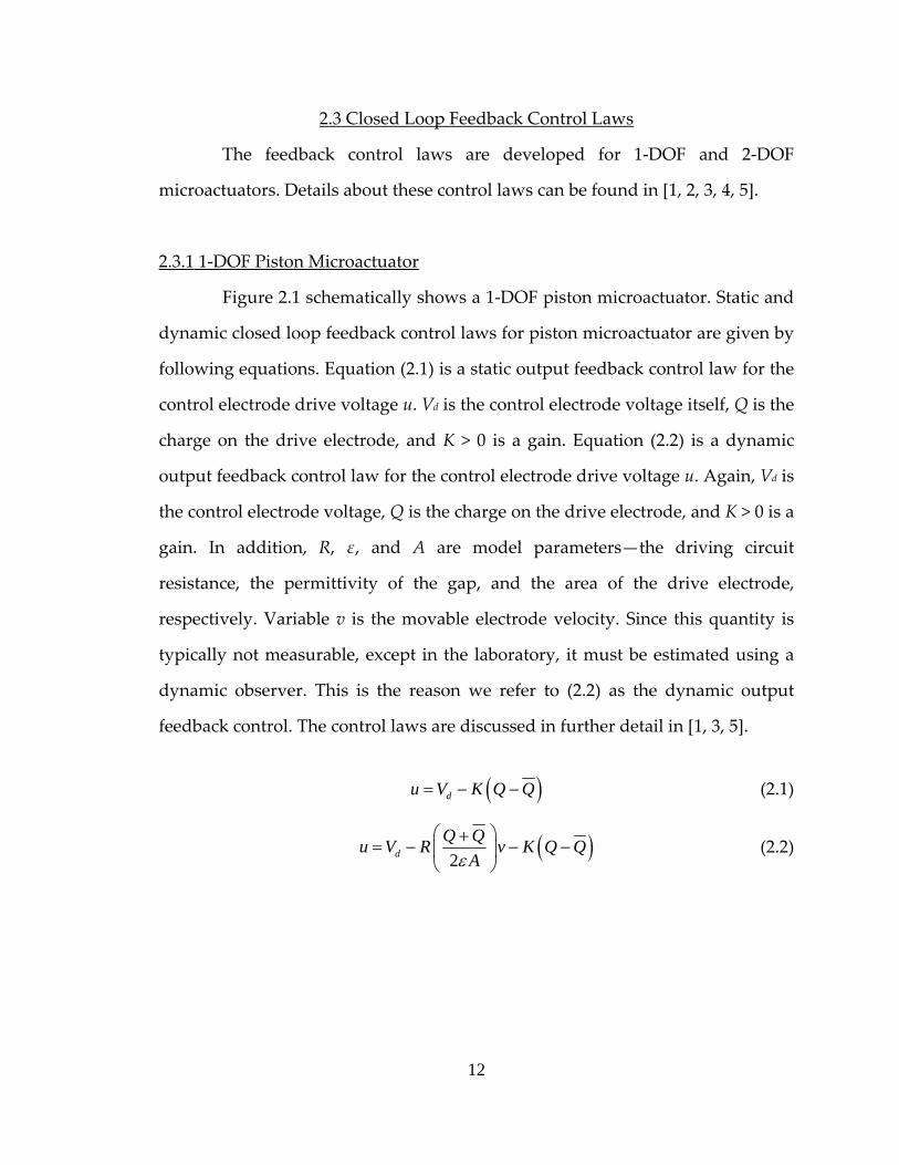
2.3 Closed Loop Feedback Control Laws
The feedback control laws are developed for 1‐DOF and 2‐DOF
microactuators. Details about these control laws can be found in [1, 2, 3, 4, 5].
2.3.1 1‐DOF Piston Microactuator
Figure 2.1 schematically shows a 1‐DOF piston microactuator. Static and
dynamic closed loop feedback control laws for piston microactuator are given by
following equations. Equation (2.1) is a static output feedback control law for the
control electrode drive voltage u. Vd is the control electrode voltage itself, Q is the
charge on the drive electrode, and K > 0 is a gain. Equation (2.2) is a dynamic
output feedback control law for the control electrode drive voltage u. Again, Vd is
the control electrode voltage, Q is the charge on the drive electrode, and K > 0 is a
gain. In addition, R, ε, and A are model parameters—the driving circuit
resistance, the permittivity of the gap, and the area of the drive electrode,
respectively. Variable v is the movable electrode velocity. Since this quantity is
typically not measurable, except in the laboratory, it must be estimated using a
dynamic observer. This is the reason we refer to (2.2) as the dynamic output
feedback control. The control laws are discussed in further detail in [1, 3, 5].
( )du V K Q Q= − − (2.1)
( )2dQ Qu V R v K Q Q
Aε⎛ ⎞+
= − − −⎜ ⎟⎝ ⎠
(2.2)
12

2.3.2 2‐DOF Breathing Mode Microactuator
A breathing mode microactuator is shown in Figures 2.2 (a) and (b). This
microactuator translates in the Y‐direction and rotates about the Z‐axis, as shown
schematically in Fig. 2.2 (a), and in the ANSYS model in Fig. 2.2 (b).
(a)
(b)
Figure 1.2: Breathing mode microactuator (a) Electromechanical Circuit (b) ANSYS Model
Static and dynamic closed loop feedback control laws for the breathing
mode microactuator are given by following equations. Here equations (2.3) and
(2.4) are the static output feedback control laws for each of the two control
electrodes, where the quantities are the same as for the 1‐DOF device, for the
appropriate electrode as indicated by the subscripts. Equations (2.5) and (2.6) are
the dynamic output feedback control laws, analogous to (2.2). Here v is the
velocity of the movable electrode center of mass, and υ is the angular velocity
about the c.m.
( )1 1 1 1du V K Q Q= − − (2.3)
( )2 2 2 2du V K Q Q= − − (2.4)
13
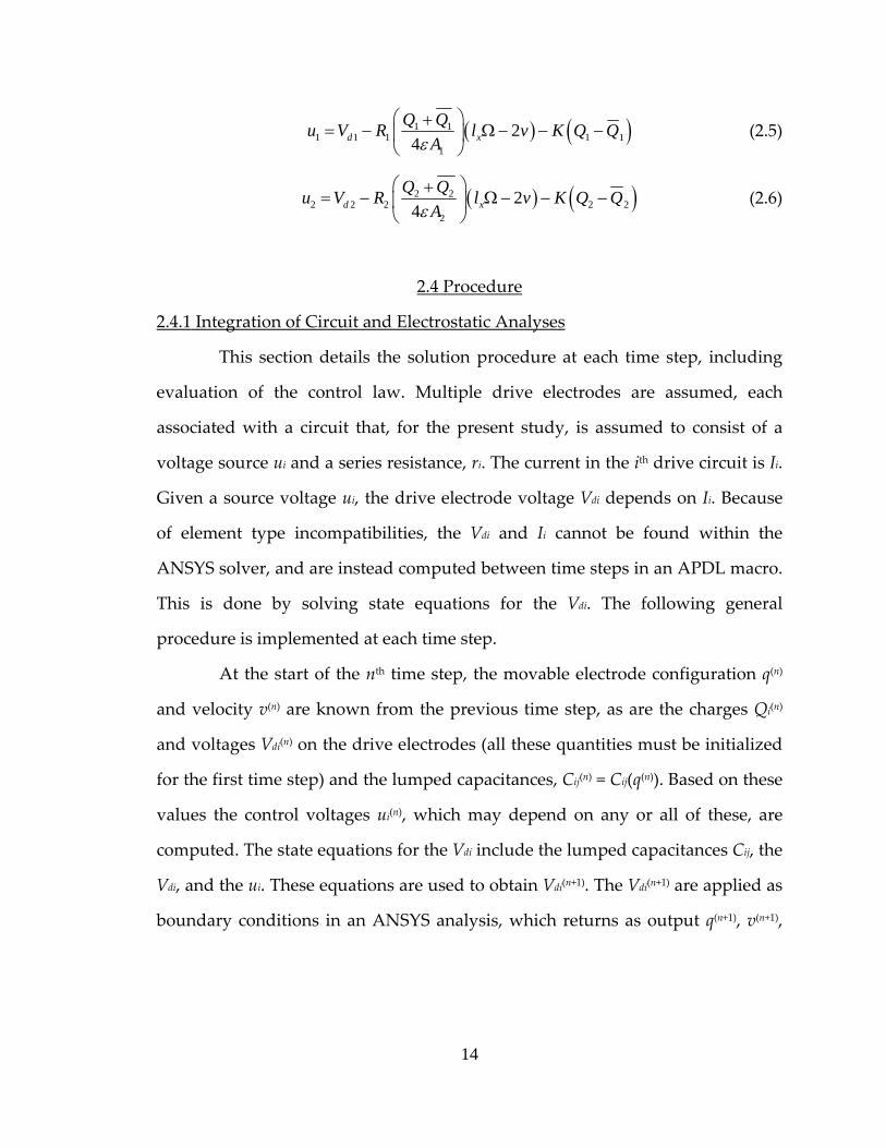
( ) ( )1 11 1 1 1 1
1
24d x
Q Qu V R l v K Q QAε
⎛ ⎞+= − Ω − − −⎜ ⎟
⎝ ⎠ (2.5)
( ) ( )2 22 2 2 2 2
2
24d x
Q Qu V R l v K Q QAε
⎛ ⎞+= − Ω − − −⎜ ⎟
⎝ ⎠ (2.6)
2.4 Procedure
2.4.1 Integration of Circuit and Electrostatic Analyses
This section details the solution procedure at each time step, including
evaluation of the control law. Multiple drive electrodes are assumed, each
associated with a circuit that, for the present study, is assumed to consist of a
voltage source ui and a series resistance, ri. The current in the ith drive circuit is Ii.
Given a source voltage ui, the drive electrode voltage Vdi depends on Ii. Because
of element type incompatibilities, the Vdi and Ii cannot be found within the
ANSYS solver, and are instead computed between time steps in an APDL macro.
This is done by solving state equations for the Vdi. The following general
procedure is implemented at each time step.
At the start of the nth time step, the movable electrode configuration q(n)
and velocity v(n) are known from the previous time step, as are the charges Qi(n)
and voltages Vdi(n) on the drive electrodes (all these quantities must be initialized
for the first time step) and the lumped capacitances, Cij(n) = Cij(q(n)). Based on these
values the control voltages ui(n), which may depend on any or all of these, are
computed. The state equations for the Vdi include the lumped capacitances Cij, the
Vdi, and the ui. These equations are used to obtain Vdi(n+1). The Vdi(n+1) are applied as
boundary conditions in an ANSYS analysis, which returns as output q(n+1), v(n+1),
14
and Qi(n+1). The q(n+1) are input to the CMATRIX macro to obtain Cij(n+1) = Cij(q(n+1)).
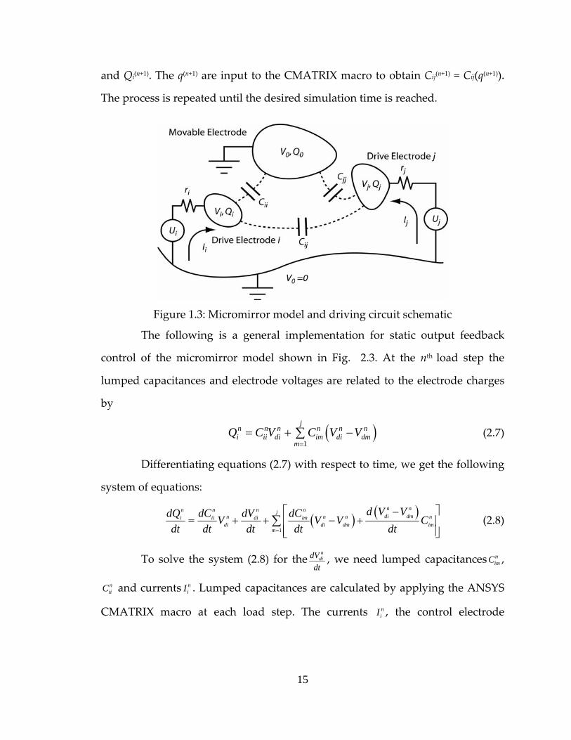
The process is repeated until the desired simulation time is reached.
Figure 1.3: Micromirror model and driving circuit schematic
The following is a general implementation for static output feedback
control of the micromirror model shown in Fig. 2.3. At the nth load step the
lumped capacitances and electrode voltages are related to the electrode charges
by
(2.7) ( )1
jn n n n n ni ii di im di dm
mQ C V C V V
== + −∑
Differentiating equations (2.7) with respect to time, we get the following
system of equations:
( ) ( )1
n nn n n njdi dmn n ni ii di im
di di dm imm
d V VdQ dC dV dCV V Vdt dt dt dt dt=
nC⎡ ⎤−
= + + − +⎢ ⎥⎢ ⎥⎣ ⎦
∑ (2.8)
To solve the system (2.8) for then
didVdt
, we need lumped capacitances ,
and currents . Lumped capacitances are calculated by applying the ANSYS
CMATRIX macro at each load step. The currents , the control electrode
nimC
niiC n
iI
niI
15

voltages Vdj(n+1) and the drive voltages uj(n+1) for the (n+1)th load step are calculated
by (2.9), (2.10), and (2.11):
n n
n i i di
i
dQ u VIdt R
−= =
ni (2.9)
1n
n n didi di n
dVV Vdt
+ t= + Δ (2.10)
( )1n n ni di iu V K Q Q+ = − − i (2.11)
2.4.2 Runge‐Kutta Adaptive Step Size Integration
Because the drive electrode voltages are not known prior to each time
step, the standard ANSYS load step utilities, including built‐in stepsize control,
cannot be used. Therefore a fourth‐order adaptive stepsize Runge‐Kutta method
is incorporated into the APDL macro to improve computational efficiency. The
implementation follows [14]. Let y1 be an FEA solution found with a stepsize of
2∆t, and y2 be another FEA solution found with two steps of size ∆t each. The
stepsize for the next time step is then
01
1n nt S t+
⎛ ⎞ΔΔ = Δ ⎜ ⎟Δ⎝ ⎠
. (2.12)
To implement this method, a target resolution is set for the norm of ∆1.
Below this limit, a significant increase (four times the current time step) in the
time step is permitted. In the ANSYS multi‐physics solver, multiframe restart is
not supported and the end time at given load step must be an integer multiple of
the current time step. Further, multiframe restart is supported only by the
nonlinear structural static or transient analysis. To work around these
limitations, which complicate implementation of the adaptive stepsize
16
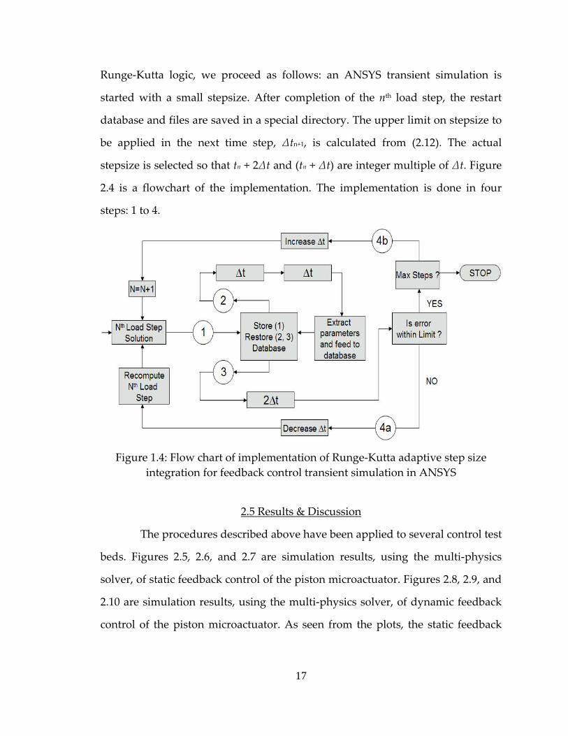
Runge‐Kutta logic, we proceed as follows: an ANSYS transient simulation is
started with a small stepsize. After completion of the nth load step, the restart
database and files are saved in a special directory. The upper limit on stepsize to
be applied in the next time step, ∆tn+1, is calculated from (2.12). The actual
stepsize is selected so that tn + 2∆t and (tn + ∆t) are integer multiple of ∆t. Figure
2.4 is a flowchart of the implementation. The implementation is done in four
steps: 1 to 4.
Figure 1.4: Flow chart of implementation of Runge‐Kutta adaptive step size
integration for feedback control transient simulation in ANSYS
2.5 Results & Discussion
The procedures described above have been applied to several control test
beds. Figures 2.5, 2.6, and 2.7 are simulation results, using the multi‐physics
solver, of static feedback control of the piston microactuator. Figures 2.8, 2.9, and
2.10 are simulation results, using the multi‐physics solver, of dynamic feedback
control of the piston microactuator. As seen from the plots, the static feedback
17

control law benefits greatly from stepsize adaptation, while the dynamic output
feedback law benefits much less. After an initial increase from 1E–10 to 1E‐8,
stepsize in the dynamic feedback case is seen to stabilize, oscillating about a
mean value. For these cases, adaptation is turned off after 20 time steps to save
on computational overhead. This difference can be justified by analyzing of the
charge behavior, as seen in Figures 2.7 and 2.10. Charge settles very fast in the
static feedback case, while it settles slowly in the dynamic feedback case. The
slower stabilization of charge in the latter case makes step size adaptation
inefficient after the initial transient.
Figure 1.5: Static feedback control for a piston microactuator (Multi‐physics
analysis): Step Size
18

Figure 1.6: Static feedback control for a piston microactuator (Multi‐physics
analysis): Gap
Figure 1.7: Static feedback control for a piston microactuator (Multi‐physics
analysis): Gap
19
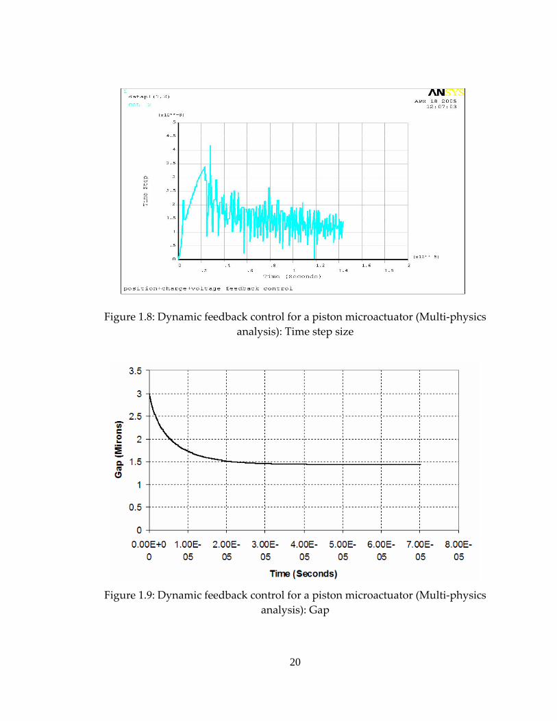
Figure 1.8: Dynamic feedback control for a piston microactuator (Multi‐physics
analysis): Time step size
Figure 1.9: Dynamic feedback control for a piston microactuator (Multi‐physics
analysis): Gap
20

Figure 1.10: Dynamic feedback control for a piston microactuator (Multi‐physics
analysis): Charge
Fig. 2.11 shows results of static feedback control simulation of piston
microactuator (parameters such as feedback control constant ‘K’ and damping
are altered for the following results) using TRANS126 elements. Since TRANS126
is used in a direct coupled field analysis, limitations due to the multi‐physics
solver tool do not apply. Therefore, the step size generated by the Runge‐Kutta
equation can be used directly. This makes the stepsize characteristics of
TRANS126 different than that generated through the multi‐physics solver.
Figures 2.12, 2.13, and 2.14 show results of static and dynamic feedback
control simulation of the 2‐DOF microactuator using the multi‐physics solver.
The ANSYS model of this micromirror is shown in Figure 2.2 (b). As seen from
the plots, this step size has a similar trend to that of the step size for the piston
microactuator.
21

Figure 1.11: Dynamic feedback control for a piston microactuator (TRANS126):
Gap and Step size
Figure 1.12: Static and Dynamic feedback control for breathing mode
microactuator (Multi‐physics analysis): Time step size
22

Figure 1.13: Static and Dynamic feedback control for breathing mode
microactuator (Multi‐physics analysis): C. M. Gap
Figure 1.14: Static and Dynamic feedback control for breathing mode microactuator (Multi‐physics analysis): Angle of tilt (Radians)
23

2.6 Conclusion
ANSYS simulation of electrostatic MEMS for validation of control laws
presents challenges due to element type incompatibilities and stepsize
management. We have embedded the FEA simulation within an APDL macro
that updates the drive circuit states and implements adaptive stepsize control.
This simulation facility has been successfully applied to a number of device
simulations. Further, Runge‐Kutta adaptive step size integration method is
observed to be very efficient for transient simulation of static feedback control
systems. This methodology has improved computational efficiency of systems
involving feedback dependent boundary conditions.
24

2.7 References
[1] D. H. S. Maithripala, B. D. Kawade, J. M. Berg, W. P. Dayawansa, “A
General Modelling and Control Framework for electrostatically actuated mechanical Systems”, International Journal of Robust and Nonlinear Control, To Appear.
[2] Robert C. Anderson, Balasaheb Kawade, Kandiah Ragulan, D. H. S.
Maithripala, Jordan M. Berg, Richard O. Gale, W. P. Dayawansa, “Integrated Charge and Position Sensing for Feedback Control of Electrostatic MEMS”, SPIE Conference on Smart Structures and Materials 2005: Sensors and Smart Structures Technologies for Civil, Mechanical, and Aerospace Systems, San Diego, CA, March, 2005.
[3] D. H. S. Maithripala, Jordan M Berg, W. P. Dayawansa, “Control of an
Electrostatic MEMS using Static and Dynamic Output Feedback”, ASME Journal of Dynamical Systems Measurement and Control, to appear, September 2005.
[4] D. H. S. Maithripala, Jordan M. Berg, W. P. Dayawansa, “Capacitive
Stabilization of an Electrostatic Actuator: An Output Feedback Viewpoint”, Proceedings of the 2003 American Control Conference, Denver, CO, June 4–6, 2003, pp. 4053–4058.
[5] Sanjeeva Maithripala, Jordan M Berg, and W. P. Dayawansa, “Nonlinear
Dynamic Output Feedback Stabilization of Electrostatically Actuated MEMS”, Proceedings of the CDC, Maui, HW, 2003.
[6] Joseph I. Seegar, and Bernhard E. Boser, “Dynamics and Control of
Parallel Plate Actuators Beyond the Electrostatic Instability”, Proceedings of the Tenth International Conference on Solid‐State Sensors and Actuators (Transducers ’99), Sendai, Japan, 7–9 June 1999; 474–477.
25
[7] Joseph I. Seegar, and Bernhard E. Boser, “Charge Control of Parallel‐Plate, Electrostatic Actuators and the Tip‐In Instability”, Journal of Microelectromechanical Systems 2003; 12(5):656–671.
[8] Jinghong Chen, Wendellin Weingartner, Alexi‐Azarov, and Randy C.
Giles, “Tilt Angle Stabilization of Electrostatically Actuated Micromechanical Mirrors Beyond the Pull‐In point”, Journal of Microelectromechanical Systems 2003; 13(6) :988‐997.
[9] Elmer S. Hung, and Stephan D. Senturia, “Generating Efficient Dynamic
Models for Microelectromechanical Systems from a Few Finite‐Element Simulation Runs”, IEEE Journal of Microelectromechanical Systems 1999; 8(3):280‐289.
[10] Mohammad I. Younis, Eihab M. Abdel‐Rahman, and Ali Nayfeh, “A
Reduced‐Order Model for Electrically Actuated Microbeam‐Based MEMS”, Journal of Microelectromechanical Systems 2003; 12(5) :672‐680.
[11] Gang Li, and N. R. Aluru, “Efficient Mixed‐Domain Analysis of
Electrostatic MEMS”, IEEE Transactions on Computer‐Aided design of integrated circuits and systems, 22(9):1228‐1242.
[12] Ofir Bochobza‐degani, David Elata, and Yael Nemirovsky, “An Efficient
DIPIE Algorithm for CAD of Electrostatically Actuated MEMS Devices”, Journal of Microelectromechanical Systems 2003; 12(5):612‐620.
[13] ANSYS Release 10.0 Documentation, ANSYS Inc, Canonsburg, PA, 2005. [14] William H. Press, Bian P. Flannery, Saul A. Teukolsky, and William T.
Vetterling, “Numerical Recipies”, 1986. [15] Yu Sun, D. Piyabongkarn, A. Sezen, B. J. Nelson, R. Rajamani, “ A high‐
aspect‐ratio tow‐axis electrostatic miroactuator with extended travel range”, Sensors and Actuators A, 2002, 102(1, 2):49‐60.
26

[16] Yael Nemirovsky, Ofir Bochobza‐Degani, “A Methodology and Model for the Pull‐In Parameters of Electrostatic Actuators”, Journal of Microelectromechanical Systems 2001; 10(4):601‐615.
[17] Edward L. Chan, Robert W. Dutton, “Electrostatic Micromechanical
Actuators with Extended Range of Travel”, Journal of Microelectromechanical Systems 2000; 9(3):321‐328.
27
CHAPTER III
3. RESULTS AND DISCUSSION
As discussed in chapter I, electrostatic microactuators have several
applications in various fields. RF MEMS Switch, piston micromirror, torsion
micromirror, and breathing mode microactuators are widely used
electromechanical actuators. In this chapter, simulation results of closed loop
static and dynamic feedback control laws for various microactuators are
presented.
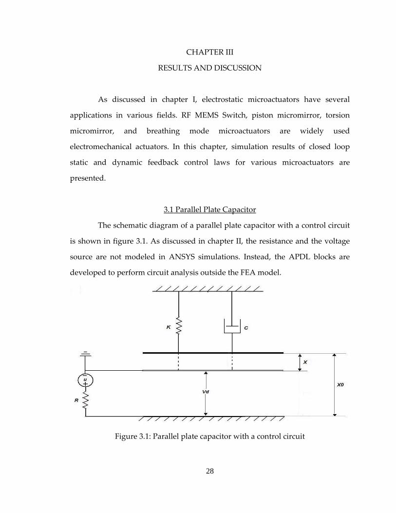
3.1 Parallel Plate Capacitor
The schematic diagram of a parallel plate capacitor with a control circuit
is shown in figure 3.1. As discussed in chapter II, the resistance and the voltage
source are not modeled in ANSYS simulations. Instead, the APDL blocks are
developed to perform circuit analysis outside the FEA model.
Figure 3.1: Parallel plate capacitor with a control circuit
28
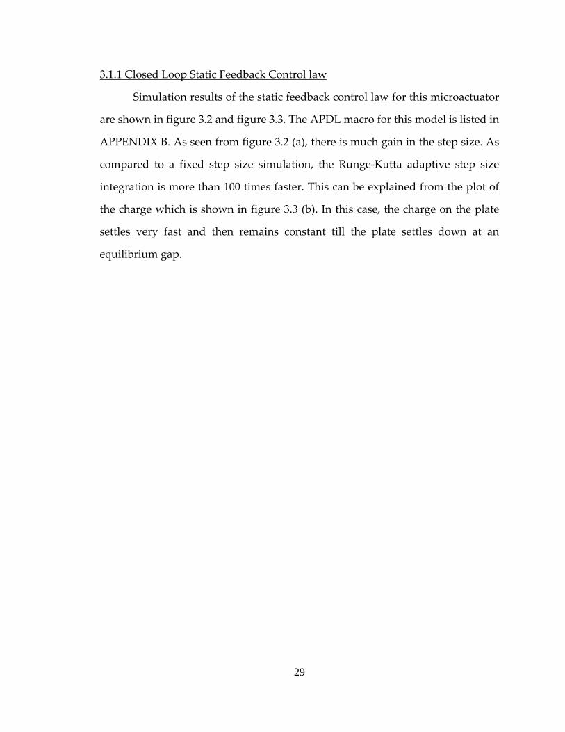
3.1.1 Closed Loop Static Feedback Control law
Simulation results of the static feedback control law for this microactuator
are shown in figure 3.2 and figure 3.3. The APDL macro for this model is listed in
APPENDIX B. As seen from figure 3.2 (a), there is much gain in the step size. As
compared to a fixed step size simulation, the Runge‐Kutta adaptive step size
integration is more than 100 times faster. This can be explained from the plot of
the charge which is shown in figure 3.3 (b). In this case, the charge on the plate
settles very fast and then remains constant till the plate settles down at an
equilibrium gap.
29
(a)
(b)
Figure 3.2: Static feedback control law simulation for the parallel plate capacitor. (a) Time Step Size vs Time (b) Gap vs Time
30

(a)
(b)
Figure 3.3: Static feedback control law simulation for the parallel plate capacitor. (a) Control Voltage vs Time (b) Charge vs Time
31

3.1.2 Closed Loop Dynamic Feedback Control Law
Simulation results of dynamic feedback control law for the same piston
microactuator are shown in figure 3.4 and figure 3.5. The APDL macro for this
model is listed in APPENDIX C. The model for dynamic feedback control law is
simulated with a fixed step size. Runge‐Kutta adaptive step size integration is
computationally expensive for a dynamic feedback control law simulation. This
can be explained from the plot of a charge which is shown in figure 3.5 (b). In
this case charge on the plate settles very slowly. Therefore, a time step size
oscillates around a mean value. This mean value is used to simulate the system
with a fixed step size, 1E‐8 seconds in this case. In case of a dynamic feedback
control simulation of breathing mode microactuator, partial adaptive and partial
fixed step size simulation is done.
Figure 3.4: Dynamic feedback control law simulation for the parallel plate capacitor, Gap vs Time
32

(a)
(b)
Figure 3.5: Dynamic feedback control law simulation for the parallel plate capacitor (a) Control Voltage vs Time (b) Charge vs Time
33

3.2 Piston Microactuator –With Parasitic Effects
The schematic diagram of a parallel plate capacitor with a parasitic
conductor and a control circuit is shown in figure 3.6. In the presence of a
parasitic plate, modified control laws are applied. This model is simulated using
the 1D transducer element, TRANS126.
Figure 3.6: Parallel plate capacitor with a parasitic conductor and a control circuit
3.2.1 Closed Loop Static Feedback Control Law Simulation
Simulation results of static feedback control law for this microactuator
are shown in figure 3.7 – figure 3.8. The APDL macro for this model is listed in
APPENDIX D. As seen from figure 3.7 (a), the nature of the time step size is
different than that for a parallel plate capacitor without a parasitic conductor.
This is because of the transducer element used in the simulation. Unlike multi‐
physics solver, it can use a time step size directly.
34

(a)
(b)
Figure 3.7: Static feedback control law simulation for a parallel plate capacitor with a parasitic conductor. (a) Time step size vs Time (b) Gap vs Time
35
(a)
(b)
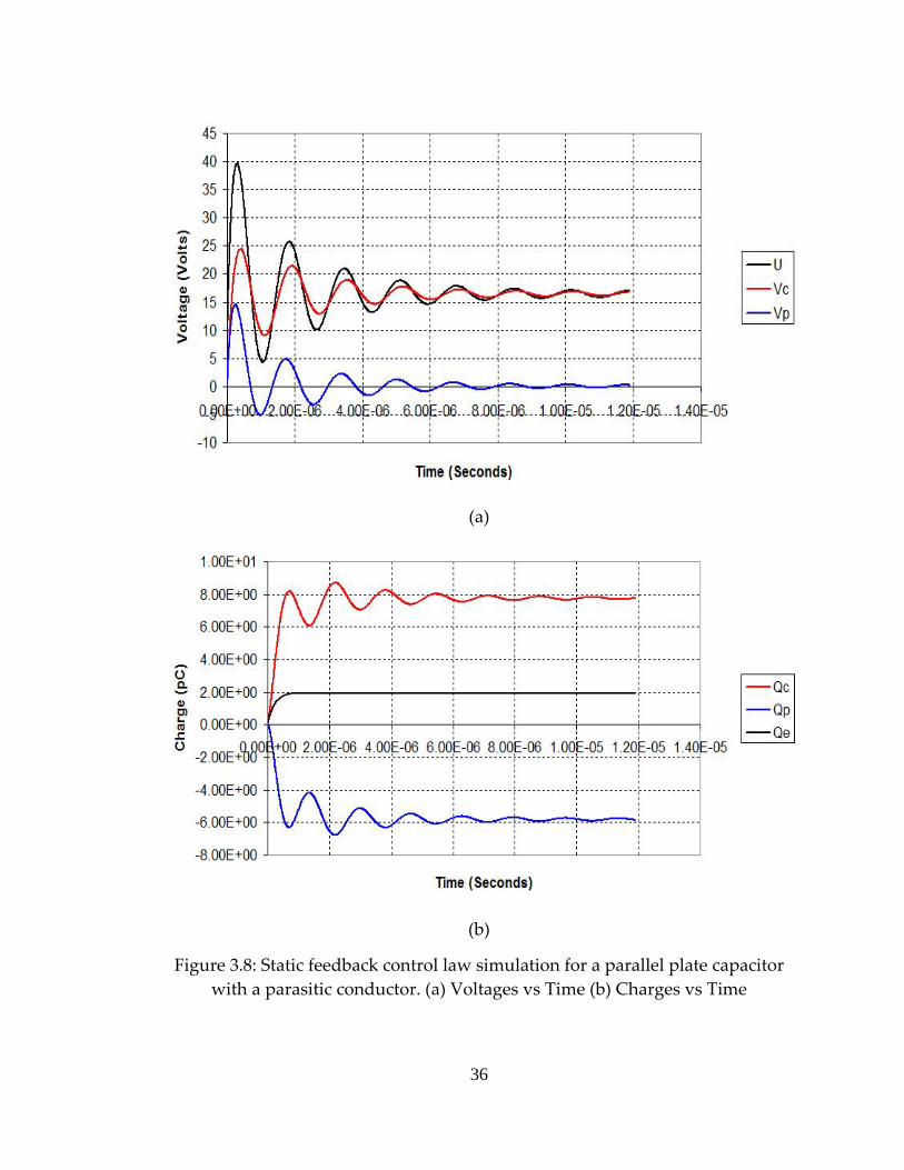
Figure 3.8: Static feedback control law simulation for a parallel plate capacitor with a parasitic conductor. (a) Voltages vs Time (b) Charges vs Time
36

3.2.2 Closed Loop Dynamic Feedback Control Law Simulation
The same parallel plate capacitor model with a parasitic conductor is
used to simulate a closed loop dynamic feedback control law. The APDL macro
for this model is listed in APPENDIX E. This model is simulated with a
transducer element, the TRANS126. The results of the simulation are shown in
figure 3.9 – figure 3.11.
Figure 3.9: Dynamic feedback control law simulation for a parallel plate capacitor with a parasitic conductor, Time step Size vs Time
37
(a)
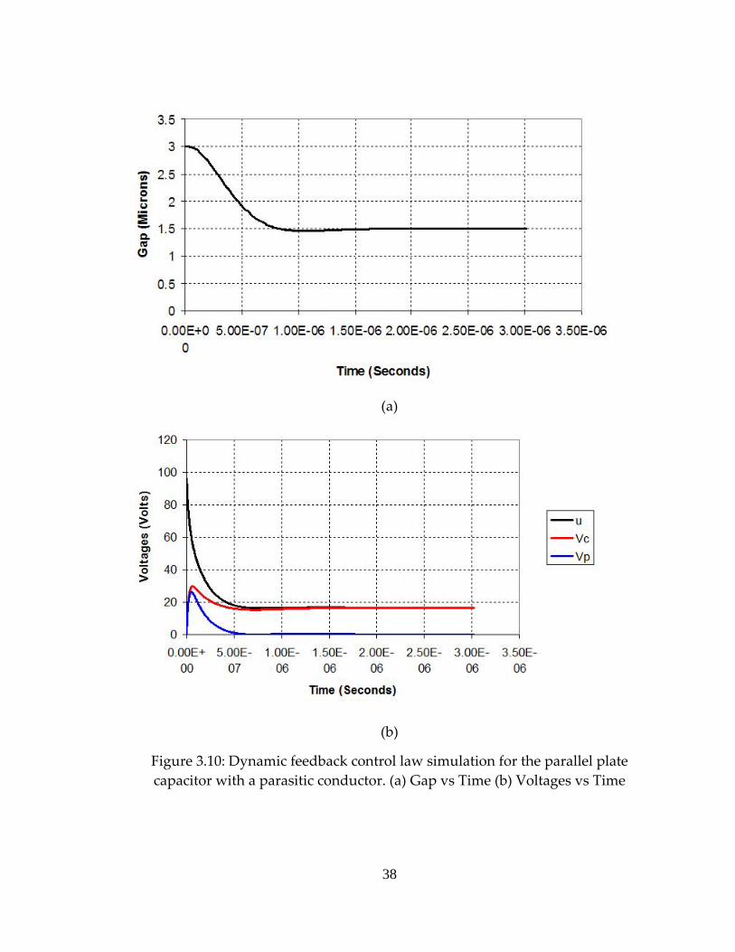
(b)
Figure 3.10: Dynamic feedback control law simulation for the parallel plate capacitor with a parasitic conductor. (a) Gap vs Time (b) Voltages vs Time
38

Figure 3.11: Dynamic feedback control law simulation for the parallel plate capacitor with a parasitic conductor, Charges vs Time
3.3 Breathing Mode Microactuators (2D)
A breathing mode microactuator simultaneously translates and rotates.
The breathing mode microactuator along with two fixed driving electrodes and
control circuits is shown in figure 3.12 (a). The ANSYS model of this
microactuator is shown in figure 3.12 (b).
39

(a)
(b)
Figure 3.12: Breathing mode microactuator. (a) Schematic digram of a microactuator with control circuits (b) ANSYS model
3.3.1 Closed Loop Static Feedback Control Law Simulation
Simulation results of a static feedback control law for the above
microactuator are shown in figure 3.13 – figure 3.16. The APDL macro for this
model is listed in APPENDIX F. This model is simulated using a multi‐physics
40

solver. The deformed configuration of the ANSYS model for the microactuator is
shown in figure 3.13. As seen from the figure 3.14 (a), the gain in the time step
size increases as the charge settles on the plate. The nature of the plot for the time
step size is same as that of the parallel plate capacitor without a parasitic
conductor.
Figure 3.13: Static feedback control law simulation for the breathing mode microactuator – Deformed configuration
41

(a)
(b)
Figure 3.14: Static feedback control law simulation for the breathing mode microactuator. (a) Time Step Size vs Time (b) C. G. Gap vs Time
42

(a)
(b)
Figure 3.15: Static feedback control law simulation for the breathing mode microactuator. (a) Angle of tilt vs Time (b) Control Voltage (U1) vs Time
43
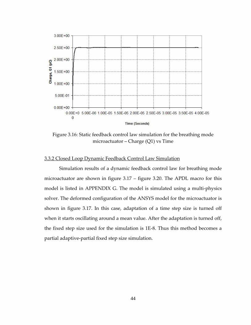
Figure 3.16: Static feedback control law simulation for the breathing mode microactuator – Charge (Q1) vs Time
3.3.2 Closed Loop Dynamic Feedback Control Law Simulation
Simulation results of a dynamic feedback control law for breathing mode
microactuator are shown in figure 3.17 – figure 3.20. The APDL macro for this
model is listed in APPENDIX G. The model is simulated using a multi‐physics
solver. The deformed configuration of the ANSYS model for the microactuator is
shown in figure 3.17. In this case, adaptation of a time step size is turned off
when it starts oscillating around a mean value. After the adaptation is turned off,
the fixed step size used for the simulation is 1E‐8. Thus this method becomes a
partial adaptive‐partial fixed step size simulation.
44
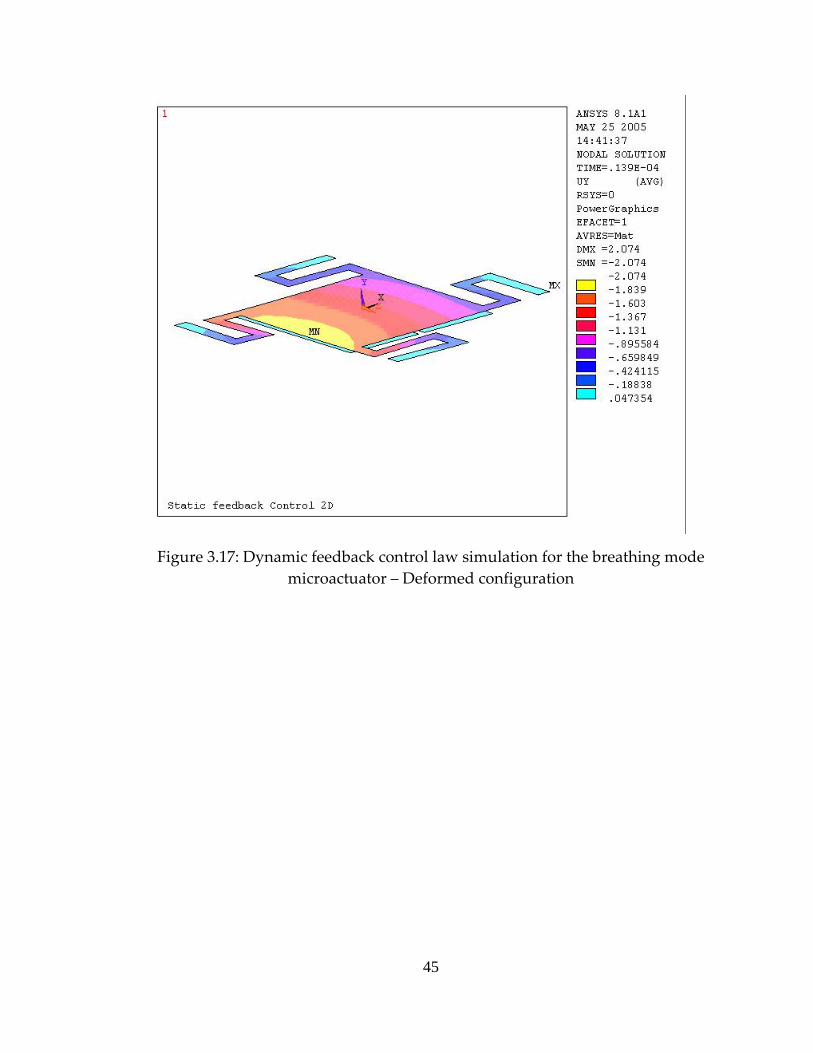
Figure 3.17: Dynamic feedback control law simulation for the breathing mode microactuator – Deformed configuration
45

(a)
(b)
Figure 3.18: Dynamic feedback control law simulation for the breathing mode microactuator. (a) Time Step Size vs Time (b) C. G. Gap vs Time
46
(a)
(b)
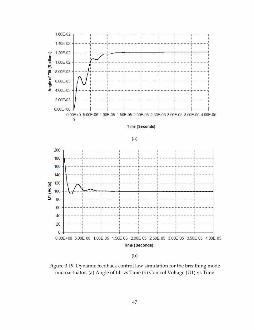
Figure 3.19: Dynamic feedback control law simulation for the breathing mode microactuator. (a) Angle of tilt vs Time (b) Control Voltage (U1) vs Time
47
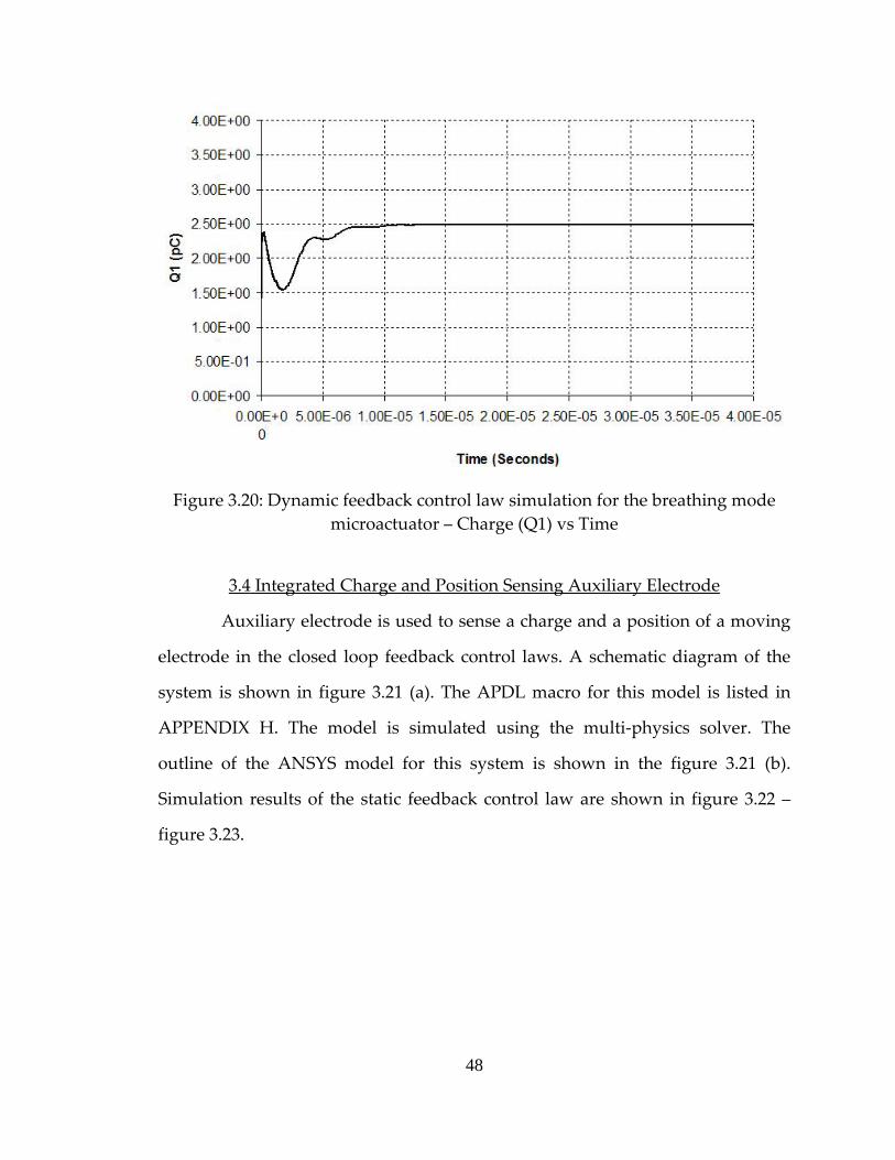
Figure 3.20: Dynamic feedback control law simulation for the breathing mode microactuator – Charge (Q1) vs Time
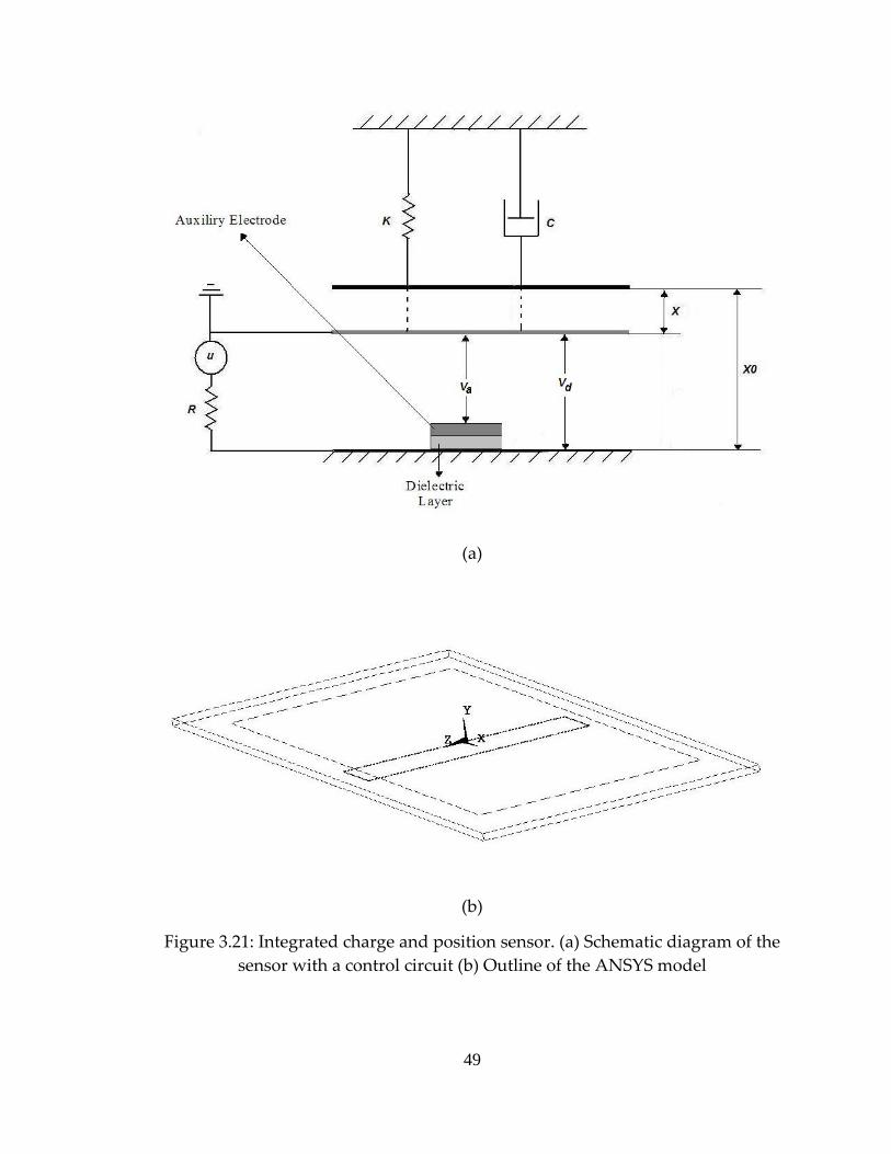
3.4 Integrated Charge and Position Sensing Auxiliary Electrode
Auxiliary electrode is used to sense a charge and a position of a moving
electrode in the closed loop feedback control laws. A schematic diagram of the
system is shown in figure 3.21 (a). The APDL macro for this model is listed in
APPENDIX H. The model is simulated using the multi‐physics solver. The
outline of the ANSYS model for this system is shown in the figure 3.21 (b).
Simulation results of the static feedback control law are shown in figure 3.22 –
figure 3.23.
48
(a)
(b)
Figure 3.21: Integrated charge and position sensor. (a) Schematic diagram of the sensor with a control circuit (b) Outline of the ANSYS model
49

(a)
(b)
Figure 3.22: Static feedback control law simulation for the integrated charge and position sensor. (a) Gap vs Time (b) Control Voltage vs Time
50
(a)
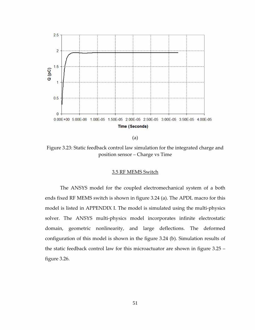
Figure 3.23: Static feedback control law simulation for the integrated charge and position sensor – Charge vs Time
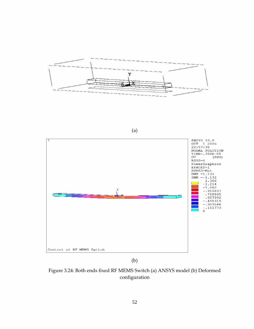
3.5 RF MEMS Switch
The ANSYS model for the coupled electromechanical system of a both
ends fixed RF MEMS switch is shown in figure 3.24 (a). The APDL macro for this
model is listed in APPENDIX I. The model is simulated using the multi‐physics
solver. The ANSYS multi‐physics model incorporates infinite electrostatic
domain, geometric nonlinearity, and large deflections. The deformed
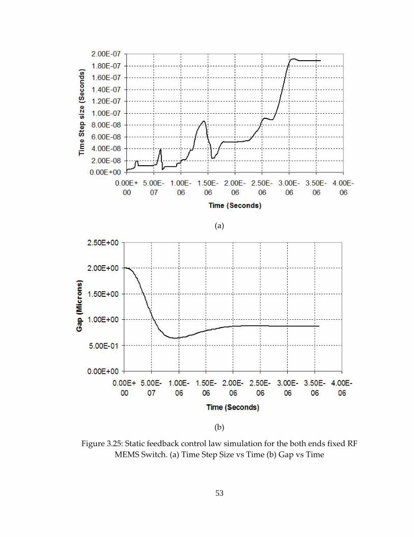
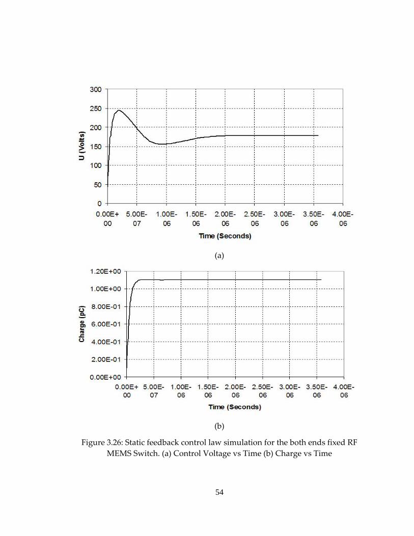
configuration of this model is shown in the figure 3.24 (b). Simulation results of
the static feedback control law for this microactuator are shown in figure 3.25 –
figure 3.26.
51
(a)
(b)
Figure 3.24: Both ends fixed RF MEMS Switch (a) ANSYS model (b) Deformed configuration
52
(a)
(b)
Figure 3.25: Static feedback control law simulation for the both ends fixed RF MEMS Switch. (a) Time Step Size vs Time (b) Gap vs Time
53
(a)
(b)
Figure 3.26: Static feedback control law simulation for the both ends fixed RF MEMS Switch. (a) Control Voltage vs Time (b) Charge vs Time
54
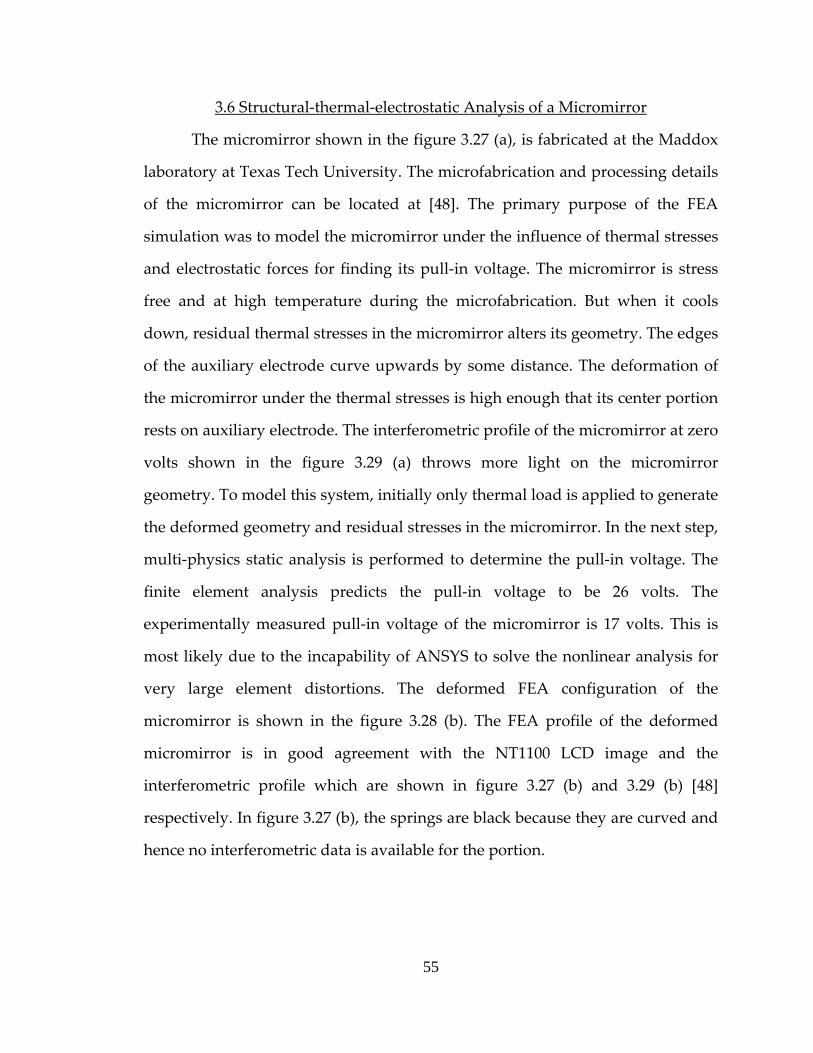
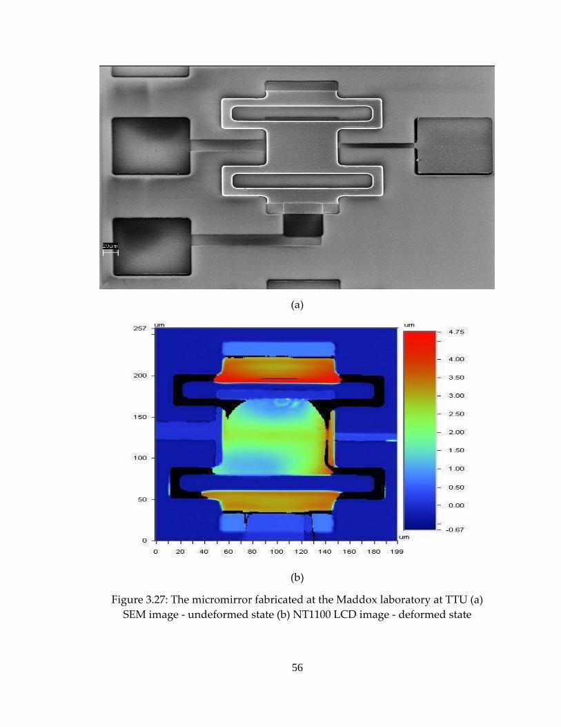
3.6 Structural‐thermal‐electrostatic Analysis of a Micromirror
The micromirror shown in the figure 3.27 (a), is fabricated at the Maddox
laboratory at Texas Tech University. The microfabrication and processing details
of the micromirror can be located at [48]. The primary purpose of the FEA
simulation was to model the micromirror under the influence of thermal stresses
and electrostatic forces for finding its pull‐in voltage. The micromirror is stress
free and at high temperature during the microfabrication. But when it cools
down, residual thermal stresses in the micromirror alters its geometry. The edges
of the auxiliary electrode curve upwards by some distance. The deformation of
the micromirror under the thermal stresses is high enough that its center portion
rests on auxiliary electrode. The interferometric profile of the micromirror at zero
volts shown in the figure 3.29 (a) throws more light on the micromirror
geometry. To model this system, initially only thermal load is applied to generate
the deformed geometry and residual stresses in the micromirror. In the next step,
multi‐physics static analysis is performed to determine the pull‐in voltage. The
finite element analysis predicts the pull‐in voltage to be 26 volts. The
experimentally measured pull‐in voltage of the micromirror is 17 volts. This is
most likely due to the incapability of ANSYS to solve the nonlinear analysis for
very large element distortions. The deformed FEA configuration of the
micromirror is shown in the figure 3.28 (b). The FEA profile of the deformed
micromirror is in good agreement with the NT1100 LCD image and the
interferometric profile which are shown in figure 3.27 (b) and 3.29 (b) [48]
respectively. In figure 3.27 (b), the springs are black because they are curved and
hence no interferometric data is available for the portion.
55
(a)
(b)
Figure 3.27: The micromirror fabricated at the Maddox laboratory at TTU (a) SEM image ‐ undeformed state (b) NT1100 LCD image ‐ deformed state
56
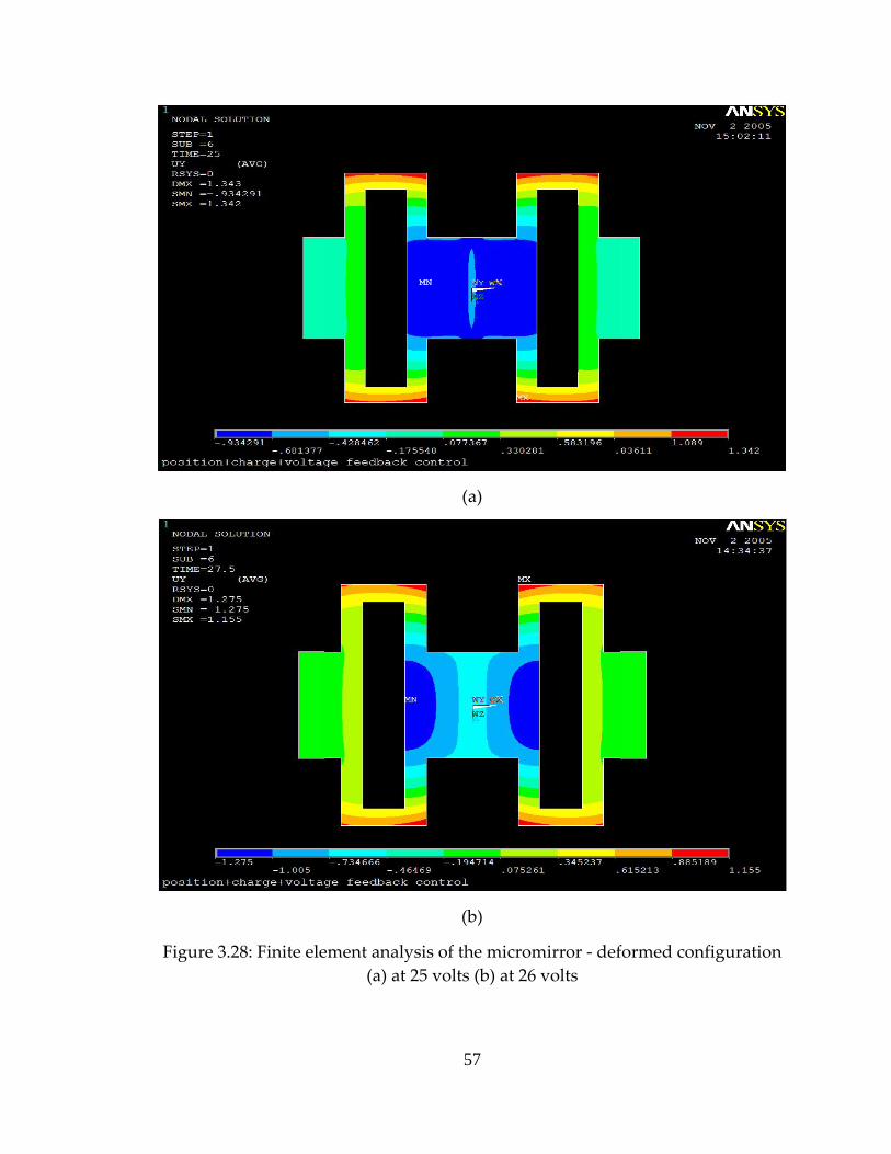
(a)
(b)
Figure 3.28: Finite element analysis of the micromirror ‐ deformed configuration (a) at 25 volts (b) at 26 volts
57

(a)
(b)
Figure 3.29: Interferometric profile for the deformed micromirror (a) at 0 volts (b) at 17 volts
58
CHAPTER IV
4.CONCLUSIONS
Computational efficiency is an important factor in finite element
simulation. Nonlinear transient analysis of a coupled electromechanical system
can be computationally inefficient due to very strict convergence criteria and
iterative procedure of the solution. These limitations along with ANSYS
limitations worsen the simulation efficiency of feedback dependent control
systems. A generalized finite element test bed proposed in this project overcomes
two ANSYS limitations: An electrostatic and circuit analysis incompatibility and
a lack of multiframe restart capability for the multi‐physics solver.
The generalized FEA test bed can be implemented for all types of
coupled electromechanical systems with various structural DOF, a new model or
the same model with different parameters. The electrostatic and circuit analyses
are successfully combined in a single analysis without using circuit elements. As
discussed in the chapter II and III, the Runge‐Kutta adaptive step size integration
is very efficient in the case of static feedback control simulations. However, it is
still demanding for dynamic feedback control simulations. The efficiency of the
dynamic feedback control simulations can be increased by incorporating partial
adaptive and partial fixed step size simulation technique. In this technique, the
adaptation of a step size is turned off when the step size exhibits oscillatory
nature. Various representative coupled electromechanical devices are tested
using this generalized test bed. These simulations justify the efficiency of the
advanced simulation technique extending the basic functionality of the ANSYS
multi‐physics package.
59
CHAPTER V
5.FUTURE WORK
The objective of this project was to develop efficient simulation
techniques for the coupled electromechanical systems. Accuracy of the finite
element analysis is dependent on the mesh density and element shape distortion
at low gaps. In coupled electromechanical systems, as the microactuator moves
towards the driving electrode, the gap between them decreases. Electrostatic
elements in the gap undergo large deformation which is a basic cause of their
distortion. In a large deflection ANSYS analysis, element distortion may become
a serious limitation. The situation can be handled by remeshing the deformed
electrostatic domain at each load step. But the multi‐physics solver doesn’t
support remeshing. Therefore this generalized test bed lacks the remeshing
feature. A solution to this problem is to develop the FEA test bed using a ‘Soft
Air’ approach. In the soft air approach, the user can locally stiffen the mesh by
assigning a low Young’s modulus to the air in the gap. It provides the user
control over the mesh deformation. However this approach is difficult to
implement because it requires advanced knowledge in ANSYS.
In all simulations, the effect of a squeeze film damping is not modeled. In
case of MEMS microactuators, gaps are so small that squeeze film damping effect
becomes significant. In this test bed, the damping is modeled via either material
property or damper element. As discussed earlier, multi‐physics solver can
accommodate any number of fields. Therefore a third field, a fluidic field can be
added in this generalized test bed to account for the squeeze film damping effect.
60
6.REFERENCES
[1] D. H. S. Maithripala, Jordan M. Berg, and W. P. Dayawansa, “An intrinsic Observer for a Class of Simple Mechanical Systems on a Lie Group”, Proceedings of the American Control Conference, 2004
[2] D. H. S. Maithripala, Jordan M. Berg, and W. P. Dayawansa, “A Port‐
controlled Hamiltonian Approach To control of an Electrostatic MEMS Actuator”, Proceedings of 2003 IMECE, Washington D.C., USA
[3] D. H. S. Maithripala, Jordan M. Berg, and W. P. Dayawansa, “Capacitive
Stabilization of an Electrostatic Actuator: An Output Feedback Viewpoint”, Proceedings of the American Control Conference 2003, pp. 4053‐4058
[4] D. H. S. Maithripala, R. O. Gale, M. W. Holtz, J. M. Berg, and W. P.
Dayawansa, “Nano‐precision control of micromirrors using output feedback”, Proceedings of the IEEE Conference on Decesion and Control 2003, pp. 2652‐2657
[5] D. H. S. Maithripala, Jordan M. Berg, and W. P. Dayawansa, “Control of
an Electrostatic MEMS using Static and Dynamic Output Feedback”, ASME Journal of Dynamic Systems, and Control
[6] Yu Sun, D. Piyabongkarn, A. Sezen, B. J. Nelson, R. Rajamani, “ A high‐
aspect‐ratio tow‐axis electrostatic miroactuator with extended travel range”, Sensors and Actuators A102: pp 49‐60
[7] Yael Nemirovsky, and Ofir Bochobza‐Degani, “A Methodology and
Model for the Pull‐In Parameters of Electrostatic Actuators”, Journal of microelectromechanical systems, 10(4): 601‐615
[8] J‐B. Lee and Charles L. Goldsmith, “Numerical Simulation of Novel
Constant‐Charge Biasing Method for Capacitive RF MEMS Switch”, Technical Proceedings of the 2003 Nanotechnology Conference and Trade Show 2003, 2(8): 396‐399
61

[9] J. Xu, R. B. Darling and P. O. Lauritzen, “Compact Modelling of Bistable
Electrostatic Actuators”, International Conference on Modeling and Simulation of Microsystems 1999, MSM(7): 289‐292
[10] H. Camon, F. Larnaudie, F. Rivoirard and B. Jammes, “Analytical
Simulation of a 1D Single Crystal Silicon Electrostatic Micromirror”, International Conference on Modeling and Simulation of Microsystems 1999, MSM(17): 628‐631
[11] J. A. Pelesko and A. A. Triolo, “Nonlocal Problems in MEMS Device
Control”, International Conference on Modeling and Simulation of Microsystems 2000, MSM(11): 509‐512
[12] J. R. Gilbert, G. K. Ananthasuresh, and S. D. Senturia, “3D Modeling of
Contact Problems and Hysteresis in Coupled Electro‐Mechanics”, IEEE MEMS Workshop 1996, pp. 127‐132
[13] Joachim Haase and Gerd Pönisch, “Determination of Turning Points in
Electromechanical Systems”, Proceedings 4th MATHMOD 2003, pp. 418‐424
[14] Jinghong Chen, Wendellin Weingartner, Alexi‐Azarov, And Randy C.
Giles, “Tilt Angle Stabilization of Electrostatically Actuated Micromechanical Mirrors Beyond the Pull‐In point”, Journal of microelectromechanical systems, 13(6): 988‐997
[15] Edward L. Chan, and Robert W. Dutton, “Electrostatic Micromechanical
Actuators with Extended Range of Travel”, Journal of microelectromechanical systems 2000, pp. 321‐328
[16] John A. Pelesko, “Mathematical Modeling of Electrostatic MEMS with
Tailored Dielectric Properties”, Society for Industrial and Applied Mathematics, 62(3): 888‐908
[17] J. A. Pelesko, and X. Y. Chen, “Electrostatic Deflections of Circular Elastic
Membranes”, Journal of Microelectronics 2003, 57(1): 1‐12
62

[18] Rafael Nadal‐Guardia, Anna Maria Brosa, and Alfons Dehé, “Constant
Charge Operation of Capacitive Sensors Based on Switched‐Current Circuits”, IEEE Sensors Journal 2003, 3(6): 835‐842
[19] Joseph I. Seegar, and Bernhard E. Boser, “Charge Control of Parallel‐Plate,
Electrostatic Actuators and the Tip‐In Instability”, Journal of microelectromechanical systems 2003, 12(5): 656‐671
[20] Luis Alexandre Rocha, Edmond Cretu, and Reinoud F. Wolffenbuttel,
“Analysis and Analytical Modeling of Static Pull‐In With Application to MEMS‐Based Voltage Reference and Process Monitoring”, Journal of microelectromechanical systems 2004, 13(2): 342‐354
[21] Arjun Selvakumar, and Khalil Najafi, “A High‐Sensitivity Z‐Axis
Capacitive Silicon Microaccelerometer with a Torsional Suspension”, Journal of microelectromechanical systems 1998, 7(2): 192‐200
[22] Edward K. Chan, Krishna Garikipati, and Robert W. Dutton,
“Characterization of Contact Electromechanics Through Capacitance Voltage Measurements and Simulations”, Journal of microelectromechanical systems 1999, 8(2): 208‐217
[23] Elmer S. Hung, and Stephan D. Senturia, “Generating Efficient Dynamic
Models for Microelectromechanical Systems from a Few Finite‐Element Simulation Runs”, Journal of microelectromechanical systems 1999, 8(3): 280‐289
[24] Luis M. Castaῆer, and Stephan D. Senturia, “Speed‐Energy Optimization
of Electrostatic Actuators Based on Pull‐In”, Journal of microelectromechanical systems 1999, 8(3): 290‐298
[25] Elmer S. Hung, and Stephan D. Senturia, “Extending the Travel Range of
Analog‐Tuned Electrostatic Actuators”, Journal of microelectromechanical systems 1999, 8(4): 497‐505
63
[26] Hiroshi Toshiyoshi, Wibool Piyawattanametha, Cheng‐Ta Chan, and Ming C. Wu, “Linearization of Electrostatically Actuated Surface Micromachined 2‐D Optical Scanner”, Journal of microelectromechanical systems 2001, 10(2): 205‐214
[27] Zhixiong Xiao, XingTao Wu, Wuyong Peng, and K. R. Farmer, “An Angle‐
Based Design Approach for Rectanular Electrostatic Torsion Actuators”, Journal of microelectromechanical systems 2001, 10(4): 561‐568
[28] Joan Pons‐Nin, Angel Rodriguez, and Luis M. Castaῆer, IEEE, “Voltage
and Pull‐In Time in Current Drive of Electrostatic Actuators”, Journal of microelectromechanical systems 2002, 11(3): 196‐205
[29] Gang Li, and N. R. Aluru, “A Lagrangian Approach for Electrostatic
Analysis of Deformable Conductors”, Journal of microelectromechanical systems 2002, 11(3): 245‐254
[30] R. Nadal‐Guardia, A. Dehé, R. Aigner, and L. M. Castaῆer, “Current Drive
Methods to Extend the Range of Travel of Electrostatic Microactuators Beyond the Voltage Pull‐In Point”, Journal of microelectromechanical systems 2002, 11(3): 255‐263
[31] Brian McCarthy, George G. Adams, Nicol E. McGruer, and David Potter,
“A Dynamic Model, Including Contact Bounce, of an Electrostatically Actuated Microswitch”, Journal of microelectromechanical systems 2002, 11(3): 276‐283
[32] John D. Grade, Hal Jerman, and Thomas W. Kenny, “Design of Large
Deflection Electrostatic Actuators”, Journal of microelectromechanical systems 2003, 12(3): 335‐343
[33] Patrick S. Riehl, Karen L. Scott, Richard S. Muller, Roger T. Howe, and
John A. Yasaitis, “Electrostatic Charge and Field Sensors Based on Micromechanical Resonators”, Journal of microelectromechanical systems 2003, 12(5): 577‐589
64
[34] Mohammad I. Younis, ASME, Eihab M. Abdel‐Rahman, and Ali Nayfeh, “A Reduced‐Order Model for Electrically Actuated Microbeam‐Based MEMS”, Journal of microelectromechanical systems 2003, 12(5): 672‐680
[35] David Elata, Ofir Bochobza‐Degani, and Yael Nemirovsky, “Analytical
Approach and Numerical α‐Lines Methods for Pull‐In Hyper‐Surface Extraction of Electrostatic Actuators With Multiple Uncoupled Voltage Sources”, Journal of microelectromechanical systems 2003, 12(5): 681‐691
[36] Sooncheol Kweon, H. Lee, and H. Shin, “Modeling and Dynamic
Simulation for Electrostatically Driven Micromirror”, International Conference on Modeling and Simulation of Microsystems 2001, 1(7): 334‐337
[37] Sanjeeva Maithripala, Jordan M Berg, and W. P. Dayawansa, “Nonlinear
Dynamic Output Feedback Stabilization of Electrostatically Actuated MEMS”, Proceedings of the 2003 IEEE Conference on Desesion and Control, Maui, December 2003, pp. 61‐66
[38] Joseph I. Seegar, and Bernhard E. Boser, “Dynamics and Control of
Parallel‐Plate Actuators Beyond the Electrostatic Instability”, International conference on Solid‐State Sensors and Actuators 1999, pp‐474‐477
[39] D. Bernstein, P. Guidotti, and J. A. Pelesko, “Mathematical Analysis of an
Electrostatically Actuated MEMS Devices”, International Conference on Modeling and Simulation of Microsystems 2000, MSM(11): 489‐492
[40] Jin‐Chern Chiou, and Yu‐Chen Lin, “A Multiple Electrostatic Electrodes
Torsion Micromirror Device With Linear Stepping Angle Effect”, Journal of microelectromechanical systems 2003, 12(6): 913‐920
[41] Zhixiong Xiao, Wuyong Peng, and K. R. Farmer, “Analytical Behavior of
Rectangular Electrostatic Torsion Actuators With Nonlinear Spring Bending”, Journal of microelectromechanical systems 2003, 12(6): 929‐936
65
[42] Gary D. Gray, Matthew J. Morgan, and Paul A. Kohl, “Electrostatic Actuators With Expanded Tuning Range Due to Biaxial Intrinsic Stress Gradients,” Journal of microelectromechanical systems 2004, 13(1): 51‐62
[43] Ofir Bochobza‐degani, David Elata, and Yael Nemirovsky, “An Efficient
DIPIE Algorithm for CAD of Electrostatically Actuated MEMS Devices” Journal of microelectromechanical systems 2002, 11(5): 612‐620
[44] Ofir Degani, Eran Socher, Tomer Leitner, Dan J. Setter, Shmuel Kaldor,
and Yael Nemirovsky, “Pull‐In Study of an Electrostatic Torsion Microactuator”, Journal of microelectromechanical systems 1998, 7(4): 373‐379
[45] Bartlomiej F. Romanowicz, “Methodology For The Modeling and
Simulation of Microsystems”, Kluwer Academic Publishers, 1998 [46] Sanjeeva Maithripala, “Nonlinear Control of an Electrostatically Actuated
MEMS”, PhD Dissertation, Texas Tech University, 2003 [47] Vijay K. Varadan, K. J. Vinoy, K. A. Jose, “RF MEMS and Their
Applications”, John Wiley & Sons Ltd, 2003 [48] Meetul Goyal, “Fabrication and Optoelectromechanical Characterization
of an Electrostatically Actuated MEMS Micromirror”, Master’s Thesis, Department of Electrical and Computer Engineering, Texas Tech University, 2005
66

APPENDIX A
7.PREREQUISITES AND SETUP REQUIREMENTS
FOR MACROS
67

Following are prerequisites and setup requirements for macros: 1. The generalized FEA test bed is developed using ANSYS Release 8.1. Please make sure that these macros should be used only with ANSYS Release 8.1 or higher. 2. Each macro must be run with the standard ANSYS Batch run. If these macros are used for the interactive run, ANSYS will fail to handle the low level memory manager. 3. These macros require a specific directory setup within the working directory. Create a directory named ‘BACKUP’ within the working directory. If it already exists in the working directory, make sure that it is empty. 4. Delete all the ANSYS results, database, load history, .out, .esav, .osav or .emat files from the working directory. It will be safe if the working directory doesn’t contain anything other than empty ‘BACKUP’ directory. 5. Depending on the complexity of the model, macros may take 6 hours to 5 days to complete the analysis. The solution can be monitored with the .txt (checksol.txt OR parf.txt) file which is created by the macro at each load step. 6. In case of a power failure or convergence failure, the analysis can be continued from the previous saved database and results file. In such a situation, follow the below procedure: 6.a Delete .out file from the working directory. 6.b Delete .esav, .osav, .rst, .rth, .db, and load history files from the working directory. Please make sure that other file must be present in the working directory. 6.c Do the changes (e.g convergence criteria) if required. Delete only those APDL blocks from the working directory for which the changes are done. Regenerate those deleted blocks and place them in the working directory 6.d Restore all files from ‘BACKUP’ directory into the working directory. 6.e Create the new input file containing the macro for ‘Do’ loop. Make sure that ‘Do’ loop starts with appropriate load step. 7. This generalized FEA test bed can be extended to accommodate a third field, a fluidic field. Create a separate APDL block for
68

the fluidic field. (For e.g. STRUCTMODEL is for structural field, ELSTATMODEL for the electrostatic field) 8. To implement this FEA test bed for any other coupled electrostatic model, make appropriate changes in few blocks. In this case, other blocks can be used as they are.
69
APPENDIX B
8.APDL MACRO FOR STATIC FEEDBACK
CONTROL FOR PISTON MICROACTUATOR
70
finish /clear /DELETE,INITIALIZATION /DELETE,STRUCTMODEL /DELETE,ELSTATMODEL /DELETE,STOREDATA /DELETE,MODIFYTIMESTEP /DELETE,SUBPROGSTART /DELETE,SUBPROGBODY /DELETE,MAINBODY *CREATE,INITIALIZATION INITIALIZE /title,position+charge+voltage feedback control /CONFIG,NRES,9999 ML=30 ! Mirror plate Length MW=30 ! Mirror plate Width MT=0.3 ! Mirror plate thickness (3000 Angstroms) tgap=3 ! Gap STIFF=7.05/4 ! SPRING STIFFNESS VALUE A=ML*MW density=2700e-18 MDAMP=0.25e-6 Qeqm=0.42 k=10 R=1e-6 EPSZRO=8.85418782e-6 Q=0 vd=0 u=0 VEL=0 m=(Ml*MW*MT)*density omegan=sqrt((4*STIFF)/m) lstno=1 cnt=1 n=700 defnode=1 maxdef=0 prevdef=0 vdprev=0 Qprev=0 VELprev=0 uprev=0 basicstep=1e-10
71

stepdt=basicstep dt=stepdt currdt=stepdt prevdt=stepdt S=0.9 pgrow=-0.20 pshrink=-0.25 shrink=0 errcon=(4/S)**(1/pgrow) delta0x=4e-4 delta0v=delta0x*omegan delta0Q=1e-3 delta0u=100 *DIM,datastr_,TABLE,10000,25,1,,, *END *CREATE,STRUCTMODEL STRUCTMOD et,1,63 mp,ex,1,70e3 mp,prxy,1,0.334 mp,dens,1,density R,1,MT WPLANE,,0,0,0,1,0,0,0,0,1 rect,-(ML/2),(ML/2),(-MW/2),(MW/2) WPCSYS,-1,0 allsel,all smrtsize,6 aatt,1,1,1 amesh,all D,ALL,ROTX,0 D,ALL,ROTY,0 D,ALL,ROTZ,0 D,ALL,UX,0 D,ALL,UZ,0 CP,1,UY,ALL sf,all,fsin,1 *get,maxnode,NODE,,NUM,MAX N,maxnode+1,-ML/2,2,-MW/2 N,maxnode+2,ML/2,2,-MW/2 N,maxnode+3,ML/2,2,MW/2 N,maxnode+4,-ML/2,2,MW/2
72
et,2,14,0,0,0 R,2,STIFF,MDAMP, TYPE,2 MAT,1 REAL,2 n1=NODE(-ML/2,0,-MW/2) n2=NODE(ML/2,0,-MW/2) n3=NODE(ML/2,0,MW/2) n4=NODE(-ML/2,0,MW/2) E,n1,maxnode+1 E,n2,maxnode+2 E,n3,maxnode+3 E,n4,maxnode+4 nsel,s,,,maxnode+1,maxnode+4,1 D,all,ALL,0 allsel,all *END *CREATE,ELSTATMODEL ELSTATMOD et,3,123 emunit,EPZRO,8.854e-6 mp,perx,2,1 morph,on block,-(ML/2),(ML/2),-tgap,0,-(MW/2),(MW/2) vsel,s,,,1 aslv,s lsla,s lsel,r,length,,ML LESIZE,ALL,,,12 lsla,s lsel,r,length,,MW LESIZE,ALL,,,12 lsla,s lsel,r,length,,tgap LESIZE,ALL,,,1 lsla,s mshape,1,3D vatt,2,,3 vmesh,all aslv,s asel,r,loc,x,-(ML/2) da,all,ux,0 aslv,s asel,r,loc,x,(ML/2) da,all,ux,0
73
aslv,s asel,r,loc,z,-(MW/2) da,all,uz,0 aslv,s asel,r,loc,z,(MW/2) da,all,uz,0 aslv,s asel,s,loc,y,-tgap, da,all,uy,0 allsel,all aslv,s asel,r,loc,y,0 nsla,s,1 CP,2,VOLT,ALL sf,all,fsin,1 allsel,all nsel,s,loc,y,-tgap,-tgap CP,3,VOLT,ALL allsel,all fini *END *CREATE,STOREDATA STOREMAC datastr_(lstno,1)=lstno datastr_(lstno,2)=stepdt datastr_(lstno,3)=dt datastr_(lstno,4)=u datastr_(lstno,5)=vd datastr_(lstno,6)=Q datastr_(lstno,7)=Qans datastr_(lstno,8)=gapact datastr_(lstno,9)=VEL datastr_(lstno,10)=CURR datastr_(lstno,11)=Q1 datastr_(lstno,12)=Q2 datastr_(lstno,13)=Q3 datastr_(lstno,14)=u1 datastr_(lstno,15)=u2 datastr_(lstno,16)=u3 datastr_(lstno,17)=vd1 datastr_(lstno,18)=vd2 datastr_(lstno,19)=vd3
74

datastr_(lstno,20)=erratioQ datastr_(lstno,21)=erratiox datastr_(lstno,22)=erratiov datastr_(lstno,23)=shstore *END *CREATE,MODIFYTIMESTEP MODISTEP int=NINT(stepdt/basicstep) takestep=basicstep int=int-1 *IF,int,EQ,0,THEN int=1 *ENDIF *IF,int,NE,1,THEN *DO,intcnt,1,int,1 stepdt=intcnt*basicstep d1=NINT((dt+(stepdt/2))*1e13) d2=NINT((stepdt/2)*1e13) rem1=MOD(d1,d2) d1=NINT((dt+stepdt)*1e13) d2=NINT((stepdt)*1e13) rem2=MOD(d1,d2) *IF,rem1,EQ,0,THEN, *IF,rem2,EQ,0,THEN takestep=stepdt *ENDIF *ENDIF *ENDDO *ENDIF stepdt=takestep *END *CREATE,SUBPROGSTART SUBPROGST *ulib,INITIALIZATION *use,INITIALIZE /prep7 *ulib,STRUCTMODEL *USE,STRUCTMOD *ulib,ELSTATMODEL
75

*USE,ELSTATMOD /solu *ulib,MAINBODY *USE,MAINBD /post1 lstno=2 prevdt=stepdt /DELETE,BACKUP\file,db /DELETE,BACKUP\field1,rst /DELETE,BACKUP\field1,esav /DELETE,BACKUP\field2,esav /DELETE,BACKUP\field1,emat /DELETE,BACKUP\field2,emat *set,extn,'s0%cnt%' SAVE,BACKUP\file,db /COPY,field1,rst,,BACKUP\field1,rst /COPY,field1,esav,,BACKUP\field1,esav /COPY,field2,esav,,BACKUP\field2,esav /COPY,field1,emat,,BACKUP\field1,emat /COPY,field2,emat,,BACKUP\field2,emat /COPY,file,extn,,BACKUP\file,extn *END *CREATE,SUBPROGBODY SUBPROGBD /prep7 *ulib,MODIFYTIMESTEP *USE,MODISTEP Qprev=Q vdprev=vd uprev=u velprev=vel cnt=cnt+1 currdt=stepdt/2 dt=dt+currdt *ulib,MAINBODY *USE,MAINBD Q1=Q u1=u
76

vd1=vd Qans1=Qans y1=abs(maxdef) vel1=vel prevdt=currdt dt=dt+currdt cnt=cnt+1 *ulib,MAINBODY *USE,MAINBD Q2=Q u2=u vd2=vd Qans2=Qans y2=abs(maxdef) vel2=vel cnt=cnt-1 *set,u *set,vd *set,Q *set,VEL *set,uprev *set,vdprev *set,Qprev *set,VELprev *set,maxdef *set,prevdef /DELETE,file,db /DELETE,field1,rst /DELETE,field2,rth /DELETE,field1,esav /DELETE,field2,esav /DELETE,field1,emat /DELETE,field2,emat *set,extn,'s0%cnt%' *IF,cnt,GT,9,THEN *set,extn,'s%cnt%' *ENDIF /DELETE,file,extn *set,extn,'s0%cnt+1%' *IF,cnt,GT,8,THEN *set,extn,'s%cnt+1%' *ENDIF /DELETE,file,extn
77
*set,extn,'s0%cnt-1%' *IF,cnt,GT,10,THEN *set,extn,'s%cnt-1%' *ENDIF /DELETE,file,extn /COPY,BACKUP\file,db,,file,db /COPY,BACKUP\field1,rst,,field1,rst /COPY,BACKUP\field1,esav,,field1,esav /COPY,BACKUP\field2,esav,,field2,esav /COPY,BACKUP\field1,emat,,field1,emat /COPY,BACKUP\field2,emat,,field2,emat /COPY,BACKUP\file,extn,,file,extn PARSAV,ALL,parf,txt FINISH /clear,NOSTART resume,file,db /SOLU *del,,prm_ PARRES,CHANGE,parf,txt currdt=stepdt *ulib,MAINBODY *USE,MAINBD Q3=Q u3=u vd3=vd Qans3=Qans y3=abs(maxdef) vel3=vel delta1x=abs(y3-y2) delta1v=abs(vel3-vel2) delta1Q=abs(Q3-Q2) delta1u=abs(u3-u2) erratiox=delta1x/delta0x erratiov=delta1v/delta0v erratioQ=delta1Q/delta0Q erratiou=delta1u/delta0u *IF,erratiox,GT,erratiov,THEN *IF,erratiox,GT,erratioQ,THEN erratio=erratiox *ELSE erratio=erratioQ
78

*ENDIF *ELSE *IF,erratiov,GT,erratioQ,THEN erratio=erratiov *ELSE erratio=erratioQ *ENDIF *ENDIF *IF,erratiou,GT,erratio,THEN erratio=erratiou *ENDIF *END *CREATE,MAINBODY MAINBD Q=Q+((u-vd)/R)*currdt CURR=(u-vd)/R /prep7 allsel,all aslv,s asel,r,loc,y,0 nsla,s,1 nsel,r,loc,x,-ML/2,ML/2 nsel,r,loc,z,-MW/2,MW/2 D,ALL,VOLT,0 SFA,ALL,,CHRGS,-Q/A allsel,all asel,s,loc,y,-tagp, nsla,s,1 nsel,r,loc,x,-ML/2,ML/2 nsel,r,loc,z,-MW/2,MW/2 SFA,ALL,,CHRGS,Q/A allsel,all fini /SOLU mfclear,SOLU,-1 fsan,off mfan,on mfel,1,1,2 mfel,2,3 mfor,2,1
79

mfco,all,1.0e-5 CNVTOL,F,1,1e-5,,1-3 CNVTOL,U,1,1e-5,,1-3 antyp,stat eqslv,iccg morph,on mfcm,2, ANTYPE,TRANS TRNOPT,FULL eqslv,iccg NSUB,5,20,1 AUTOTS,ON KBC,0 nlgeom,on morph,off mfcm,1 *IF,LSTNO,NE,1,THEN, MFRSTART,dt-currdt *ENDIF mfti,dt mfdt,currdt mfou,1 mfit,15 mfint,cons mfsu,1,2,forc,1 mfsu,1,1,disp,2 outres,all,all LSWRITE,cnt LSSOLVE,cnt,cnt,1 fini /post1 allsel,all file,field2,rth set,last,last nsel,s,loc,y,-tgap,-tgap *get,mincond1,NODE,0,NUM,MIN, *GET,vd,NODE,mincond1,VOLT allsel,all fini /POST26 reset
80

prevdef=maxdef file,field1,rst NSOL,2,defnode,U,Y DERIV,3,2,1,,VEL_1UY *GET,maxdef,VARI,2,RTIME,dt *GET,VEL,VARI,3,RTIME,dt *IF,cnt,LT,5,THEN VEL=((maxdef-prevdef)/prevdt) *ENDIF u=vd-k*(Q-Qeqm) gapact=tgap-abs(maxdef) Qans=((EPSZRO*A)/(gapact))*vd /DELETE,field2,rth *END !*********************************** START OF MAIN PROGRAM *********************************** *ulib,SUBPROGSTART *USE,SUBPROGST *DO,lstno,2,n,1 *ulib,SUBPROGBODY *USE,SUBPROGBD *IF,erratio,GT,1,THEN shrink=1 shstore=0 *DOWHILE,shrink stepdt=S*stepdt*((erratio)**pshrink) *IF,stepdt,GT,basicstep,THEN *set,cnt *set,dt *set,u *set,vd *set,Q *set,VEL *set,uprev *set,vdprev *set,Qprev *set,VELprev *set,Qans *set,maxdef
81

*set,prevdef *set,prevdt *set,currdt *set,extn *set,gapact *del,,prm_ PARSAV,ALL,shrinkpar,txt /prep7 /DELETE,file,db /DELETE,field1,rst /DELETE,field1,esav /DELETE,field2,esav /DELETE,field1,emat /DELETE,field2,emat /COPY,BACKUP\file,db,,file,db /COPY,BACKUP\field1,rst,,field1,rst /COPY,BACKUP\field1,esav,,field1,esav /COPY,BACKUP\field2,esav,,field2,esav /COPY,BACKUP\field1,emat,,field1,emat /COPY,BACKUP\field2,emat,,field2,emat FINISH /clear,NOSTART resume,file,db /prep7 PARRES,CHANGE,shrinkpar,txt /DELETE,file,extn /COPY,BACKUP\file,extn,,file,extn *ulib,SUBPROGBODY *USE,SUBPROGBD *IF,erratio,LT,1,THEN shrink=-1 *ENDIF shstore=shstore+1 *ELSE shrink=-1 *ENDIF *ENDDO *ENDIF prevdt=stepdt
82
*ULIB,STOREDATA *USE,STOREMAC shstore=0 *IF,erratio,GT,errcon,THEN stepdt=S*stepdt*((erratio)**pgrow) *ELSE stepdt=4*stepdt *ENDIF *set,extn,'s0%cnt%' *IF,cnt,GT,9,THEN *set,extn,'s%cnt%' *ENDIF *set,extnprev,'s0%cnt-1%' *IF,cnt,GT,10,THEN *set,extnprev,'s%cnt-1%' *ENDIF /DELETE,BACKUP\file,db /DELETE,BACKUP\field1,rst /DELETE,BACKUP\field1,esav /DELETE,BACKUP\field2,esav /DELETE,BACKUP\field1,emat /DELETE,BACKUP\field2,emat /DELETE,BACKUP\file,extnprev /DELETE,file,extnprev SAVE,BACKUP\file,db /COPY,field1,rst,,BACKUP\field1,rst /COPY,field1,esav,,BACKUP\field1,esav /COPY,field2,esav,,BACKUP\field2,esav /COPY,field1,emat,,BACKUP\field1,emat /COPY,field2,emat,,BACKUP\field2,emat /COPY,file,extn,,BACKUP\file,extn PARSAV,ALL,checksol,txt *ENDDO !*********************************** END OF MAIN PROGRAM *********************************** SAVE *DIM,datapl,TABLE,lstno-1,25,1, , , *MFUN,datapl(1,1),COPY,datastr_(1,1) /GROPT,VIEW,1
83

*VPLOT,datapl(1,3),datapl(1,8) /AXLAB,X,TIME /AXLAB,Y,GAP
84
APPENDIX C
9.APDL MACRO FOR DYNAMIC FEEDBACK
CONTROL FOR PISTON
10.MICROACTUATOR
85

/batch,list /title,position+charge+voltage feedback control /CONFIG,NRES,9999 ML=30 ! Mirror plate Length MW=30 ! Mirror plate Width MT=0.3 ! Mirror plate thickness (3000 Angstroms) tgap=3 ! Gap PERMT=3.8 ! Permittivity of dielectric layer STIFF=7.05/4 ! SPRING STIFFNESS VALUE A=ML*MW MDAMP=0.25e-6 Qeqm=0.42 Q=0 k=50 R=1e-6 EPSZRO=8.85418782e-6 VEL=0 vd=0 u=0 cnt=1 n=9000 defnode=1 stepdt=1e-8 dt=stepdt prevdef=0 *DIM,datastr,TABLE,10000,30 /prep7 et,1,63 mp,ex,1,70e3 mp,prxy,1,0.334 mp,dens,1,2700e-18 R,1,MT WPLANE,,0,0,0,1,0,0,0,0,1 rect,-(ML/2),(ML/2),(-MW/2),(MW/2) WPCSYS,-1,0 allsel,all smrtsize,7 aatt,1,1,1 amesh,all D,ALL,ROTX,0 D,ALL,ROTY,0
86

D,ALL,ROTZ,0 D,ALL,UX,0 D,ALL,UZ,0 CP,1,UY,ALL sf,all,fsin,1 *get,maxnode,NODE,,NUM,MAX N,maxnode+1,-ML/2,2,-MW/2 N,maxnode+2,ML/2,2,-MW/2 N,maxnode+3,ML/2,2,MW/2 N,maxnode+4,-ML/2,2,MW/2 et,2,14,0,0,0 R,2,STIFF,MDAMP, TYPE,2 MAT,1 REAL,2 n1=NODE(-ML/2,0,-MW/2) n2=NODE(ML/2,0,-MW/2) n3=NODE(ML/2,0,MW/2) n4=NODE(-ML/2,0,MW/2) E,n1,maxnode+1 E,n2,maxnode+2 E,n3,maxnode+3 E,n4,maxnode+4 nsel,s,,,maxnode+1,maxnode+4,1 D,all,ALL,0 allsel,all et,3,123 emunit,EPZRO,8.854e-6 mp,perx,2,1 morph,on block,-(ML/2),(ML/2),-tgap,0,-(MW/2),(MW/2) vsel,s,,,1 aslv,s lsla,s lsel,r,length,,ML LESIZE,ALL,,,10 lsla,s lsel,r,length,,MW LESIZE,ALL,,,10 lsla,s lsel,r,length,,tgap LESIZE,ALL,,,1 lsla,s
87
mshape,1,3D vatt,2,,3 vmesh,all aslv,s asel,r,loc,x,-(ML/2) da,all,ux,0 aslv,s asel,r,loc,x,(ML/2) da,all,ux,0 aslv,s asel,r,loc,z,-(MW/2) da,all,uz,0 aslv,s asel,r,loc,z,(MW/2) da,all,uz,0 aslv,s asel,s,loc,y,-tgap, da,all,uy,0 allsel,all aslv,s asel,r,loc,y,0 nsla,s,1 CP,2,VOLT,ALL sf,all,fsin,1 aslv,s asel,r,loc,y,0 nsla,s,1 SFA,ALL,,CHRGS,0 D,ALL,VOLT,0 allsel,all nsel,s,loc,y,-tgap,-tgap CP,3,VOLT,ALL allsel,all SFA,ALL,,CHRGS,0 allsel,all fini /solu mfan,on mfel,1,1,2 mfel,2,3 mfor,2,1
88

mfco,all,1.0e-5 cnvtol,F,,,,1e-6 antyp,stat eqslv,iccg morph,on mfcm,2, ANTYPE,TRANS TRNOPT,FULL eqslv,iccg NSUB,1 KBC,0 nlgeom,on morph,off mfcm,1 mfti,stepdt mfdt,stepdt mfou,1 mfit,4 mfint,cons mfsu,1,2,forc,1 mfsu,1,1,disp,2 LSWRITE,1 outres,all LSSOLVE,1,1,1 *DO,lstno,2,n,1 cnt=cnt+1 /post1 allsel,all file,field2,rth set,last,last nsel,s,loc,y,-tgap, nsel,r,loc,x,-ML/2,ML/2 nsel,r,loc,z,-MW/2,MW/2 *get,mincond1,NODE,0,NUM,MIN, *GET,vd,NODE,mincond1,VOLT allsel,all fini /POST26 file,field1,rst
89

NSOL,2,defnode,U,Y DERIV,3,2,1,,VEL_1UY *GET,defact,VARI,2,RTIME,dt *GET,VEL,VARI,3,RTIME,dt *IF,LSTNO,LT,5,THEN VEL=((defact-prevdef)/stepdt) *ENDIF gapact=tgap-abs(defact) u=vd-k*(Q-Qeqm)+R*VEL*((Q+Qeqm)/(2*EPSZRO*A)) Qload=Q+((u-vd)/R)*stepdt Qans=((EPSZRO*A)/(gapact))*vd CURR=(u-vd)/R datastr(lstno-1,1)=lstno datastr(lstno-1,2)=dt datastr(lstno-1,3)=u datastr(lstno-1,4)=vd datastr(lstno-1,5)=Qans datastr(lstno-1,6)=Q datastr(lstno-1,7)=CURR datastr(lstno-1,8)=gapact datastr(lstno-1,9)=VEL datastr(lstno-1,10)=R*VEL*((Q+Qeqm)/(2*EPSZRO*A)) Q=Qload dt=dt+stepdt prevdef=defact /DELETE,field2,rth /prep7 allsel,all aslv,s asel,r,loc,y,0 nsla,s,1 nsel,r,loc,x,-ML/2,ML/2 nsel,r,loc,z,-MW/2,MW/2 SFA,ALL,,CHRGS,-Q/A allsel,all asel,s,loc,y,-tgap nsla,s,1 nsel,r,loc,x,-ML/2,ML/2 nsel,r,loc,z,-MW/2,MW/2 SFA,ALL,,CHRGS,Q/A allsel,all fini
90
/solu mfclear,SOLU,-1 fsan,off mfan,on mfel,1,1,2 mfel,2,3 mfor,2,1 mfco,all,1.0e-5 cnvtol,F,,,,1e-6 antyp,stat eqslv,iccg morph,on mfcm,2, ANTYPE,TRANS TRNOPT,FULL eqslv,iccg NSUB,1 KBC,0 nlgeom,on morph,off mfcm,1 MFRSTART,dt-stepdt mfti,dt mfdt,stepdt mfou,1 mfit,8 mfint,cons mfsu,1,2,forc,1 mfsu,1,1,disp,2 outres,all LSWRITE,cnt LSSOLVE,cnt,cnt,1 *set,extn,'s0%cnt-1%' *IF,cnt,GT,10,THEN *set,extn,'s%cnt-1%' *ENDIF /DELETE,file,extn PARSAV,ALL,parf,txt *ENDDO /GROPT,view,1 *DIM,datapl,TABLE,lstno-1,30,1, , , *MFUN,datapl(1,1),COPY,datastr(1,1) *VPLOT,datapl(1,2),datapl(1,8)
91

/AXLAB,X,TIME /AXLAB,Y,GAP
92
APPENDIX D
11.APDL MACRO FOR STATIC FEEDBACK
CONTROL FOR PISTON
12.MICROACTUATOR
13.WITH PARASITIC
14. EFFECTS
93

/DELETE,INITIALIZATION /DELETE,STRUCTMODEL /DELETE,STOREDATA /DELETE,SUBPROGSTART /DELETE,SUBPROGBODY /DELETE,MAINBODY /DELETE,GETCTRLMAC /DELETE,CCALMAC *CREATE,INITIALIZATION INITIALIZE /title,Control of TI DMD /CONFIG,NRES,9999 /FILNAME,file,1 ML=200 ! Mirror plate Length MW=100 ! Mirror plate Width MT=0.8 ! Mirror plate thickness (3000 Angstroms) gap=3 ! Gap pgap=0.5 ! parasitic Gap STIFF=7.05 ! SPRING STIFFNESS VALUE A=ML*MW EPSZRO=8.85418782e-6 Cpp=(EPSZRO*A) DENSITY=2700e-18 m=ML*MW*MT*DENSITY DAMP=5e-7 R=1e-6 Rc=R Rp=R Qeqm=1.93 k=5*1E6 Q=0 u=0 vp=0 vc=0 def=0 prevdef=0 lstno=1 cnt=0 n=5000 basicstep=1e-10 stepdt=basicstep
94
dt=stepdt currdt=stepdt prevdt=stepdt S=0.9 pgrow=-0.20 pshrink=-0.25 shrink=0 errcon=(4/S)**(1/pgrow) delta0x=1 delta0v=250 delta0Q=Qeqm*8e-4 *DIM,datastr_,TABLE,10000,30 *DIM,capdata,ARRAY,20,4 *END *CREATE,STRUCTMODEL STRUCTMOD capdata(1,1)=3 capdata(2,1)=2.85 capdata(3,1)=2.7 capdata(4,1)=2.55 capdata(5,1)=2.4 capdata(6,1)=2.25 capdata(7,1)=2.1 capdata(8,1)=1.95 capdata(9,1)=1.8 capdata(10,1)=1.65 capdata(11,1)=1.5 capdata(12,1)=1.35 capdata(13,1)=1.2 capdata(14,1)=1.05 capdata(15,1)=0.9 capdata(16,1)=0.75 capdata(17,1)=0.6 capdata(18,1)=0.45 capdata(19,1)=0.30 capdata(20,1)=0.15 capdata(1,2)=0.059 capdata(2,2)=0.062105263 capdata(3,2)=0.065555556 capdata(4,2)=0.069411765 capdata(5,2)=0.07375 capdata(6,2)=0.078666667
95
capdata(7,2)=0.084285714 capdata(8,2)=0.090769231 capdata(9,2)=0.098333333 capdata(10,2)=0.107272727 capdata(11,2)=0.118 capdata(12,2)=0.131111111 capdata(13,2)=0.1475 capdata(14,2)=0.168571429 capdata(15,2)=0.196666667 capdata(16,2)=0.236 capdata(17,2)=0.295 capdata(18,2)=0.393333333 capdata(19,2)=0.59 capdata(20,2)=1.18 !-------------------- Define Cdd ------------------------------------------- ET,1,TRANS126,,2,1,,, r,1,,1,gap, rmore,capdata(1,1),capdata(1,2),capdata(2,1),capdata(2,2),capdata(3,1),capdata(3,2) rmore,capdata(4,1),capdata(4,2),capdata(5,1),capdata(5,2),capdata(6,1),capdata(6,2) rmore,capdata(7,1),capdata(7,2),capdata(8,1),capdata(8,2),capdata(9,1),capdata(9,2) rmore,capdata(10,1),capdata(10,2),capdata(11,1),capdata(11,2),capdata(12,1),capdata(12,2) rmore,capdata(13,1),capdata(13,2),capdata(14,1),capdata(14,2),capdata(15,1),capdata(15,2) rmore,capdata(16,1),capdata(16,2),capdata(17,1),capdata(17,2),capdata(18,1),capdata(18,2) rmore,capdata(19,1),capdata(19,2),capdata(20,1),capdata(20,2) n,1 n,2,,gap type,1 real,1 e,1,2 !-------------------- Define Cpp ------------------------------------------- ET,2,trans126,,2 r,2,,2,pgap rmore,Cpp n,3,,-pgap
96

type,2 real,2 e,3,1 !------------------------- Define Rc------------------- ET,3,CIRCU124, r,3,R type,3 real,3 n,4,-gap e,4,1 !------------------------- Define Rpp------------------- n,5,gap e,3,5 !------------------------- Short Ground------------------- ET,4,200,0,0,0,0 TYPE,4 E,2,5 !------------------------- Define mirror plate ------------------- RECT,,ML/2,gap,gap+MT RECT,,-ML/2,gap,gap+MT aglue,all ET,5,42 R,5,MW MP,EX,5,73.1E3,0 ! Young's modulus of material no.1 MP,PRXY,5,0.35,0 ! Poisson's ratio of material no.1 mp,dens,5,2700e-18 aatt,5,5,5 smrtsize,10 amesh,all !------------------------- Define Spring------------------- *get,maxnode,NODE,0,NUM,MAX n,maxnode+1,,gap ET,6,14,,2 r,6,STIFF,DAMP
97

type,6 real,6 e,maxnode+1,2 !------------------------- Apply constraints ------------------- allsel,all D,1,uy,0 D,3,uy,0 D,maxnode+1,all,0 nsla,s,1 D,all,ux,0 nsel,a,,,2 CP,1,UY,all allsel,all nsel,s,,,2 nsel,a,,,5 CP,2,VOLT,all D,all,VOLT,0 allsel,all !------------------------- Apply Load------------------- D,4,VOLT,0 finish *END *CREATE,STOREDATA STOREMAC datastr_(lstno,1)=lstno datastr_(lstno,2)=stepdt datastr_(lstno,3)=dt datastr_(lstno,4)=u datastr_(lstno,5)=vc datastr_(lstno,6)=vp datastr_(lstno,7)=Qc datastr_(lstno,8)=Qp datastr_(lstno,9)=Q datastr_(lstno,10)=erratioQ datastr_(lstno,11)=erratiox datastr_(lstno,12)=erratiov datastr_(lstno,13)=abs(def) datastr_(lstno,14)=gap-abs(def) datastr_(lstno,15)=vel *END
98

*CREATE,MODIFYTIMESTEP MODISTEP int=NINT(stepdt/basicstep) takestep=basicstep int=int-1 *IF,int,EQ,0,THEN int=1 *ENDIF *IF,int,NE,1,THEN *DO,intcnt,1,int,1 stepdt=intcnt*basicstep d1=NINT((dt+(stepdt/2))*1e13) d2=NINT((stepdt/2)*1e13) rem1=MOD(d1,d2) d1=NINT((dt+stepdt)*1e13) d2=NINT((stepdt)*1e13) rem2=MOD(d1,d2) *IF,rem1,EQ,0,THEN, *IF,rem2,EQ,0,THEN takestep=stepdt *ENDIF *ENDIF *ENDDO *ENDIF stepdt=takestep *END *CREATE,SUBPROGSTART SUBPROGST *ulib,INITIALIZATION *use,INITIALIZE /prep7 *ulib,STRUCTMODEL *USE,STRUCTMOD /solu *ulib,MAINBODY *USE,MAINBD /post1 lstno=2 prevdt=stepdt
99

/DELETE,BACKUP\file,db /DELETE,BACKUP\file,rst /DELETE,BACKUP\file,esav /DELETE,BACKUP\file,emat SAVE,BACKUP\file,db /COPY,file,rst,,BACKUP\file,rst /COPY,file,esav,,BACKUP\file,esav /COPY,file,emat,,BACKUP\file,emat *END *CREATE,SUBPROGBODY SUBPROGBD cnt=cnt+1 currdt=stepdt/2 dt=dt+currdt *ulib,MAINBODY *USE,MAINBD Q1=Q u1=u vc1=vc vp1=vp vel1=vel prevdt=currdt dt=dt+currdt cnt=cnt+1 *ulib,MAINBODY *USE,MAINBD Q2=Q u2=u vc2=vc vp2=vp vel2=vel cnt=cnt-1 *set,u *set,vc *set,vp *set,Q *set,VEL
100

*set,def *set,prevdef /DELETE,file,db /DELETE,file,rst /DELETE,file,esav /DELETE,file,emat /COPY,BACKUP\file,db,,file,db /COPY,BACKUP\file,rst,,file,rst /COPY,BACKUP\file,esav,,file,esav /COPY,BACKUP\file,emat,,file,emat PARSAV,ALL,parf,txt FINISH /clear,NOSTART resume,file,db /SOLU *del,,prm_ PARRES,CHANGE,parf,txt currdt=stepdt *ulib,MAINBODY *USE,MAINBD Q3=Q u3=u vc3=vc vp3=vp vel3=vel delta1x=0 delta1v=abs(vel3-vel2) delta1Q=abs(Q3-Q2) erratiox=delta1x/delta0x erratiov=delta1v/delta0v erratioQ=delta1Q/delta0Q *IF,erratiox,GT,erratiov,THEN *IF,erratiox,GT,erratioQ,THEN erratio=erratiox *ELSE erratio=erratioQ *ENDIF *ELSE *IF,erratiov,GT,erratioQ,THEN
101
erratio=erratiov *ELSE erratio=erratioQ *ENDIF *ENDIF *END *CREATE,MAINBODY MAINBD /prep7 *IF,lstno,NE,1,THEN u=Rc*(((1/Rc)+(1/Rp))*vc+(pgap/(Rp*EPSZRO*A))*Qp-k*(Q-Qeqm)) D,4,VOLT,u *ENDIF /SOLU *IF,lstno,NE,1,THEN ANTYPE,trans,restart *ELSE ANTYPE,TRANS TRNOPT,FULL *ENDIF nlgeom,on CNVTOL,F,1,1E-12 CNVTOL,VOLT,1,1E-12 AUTOTS,ON NSUB,1 NEQIT,40 time,dt outres,all,last solve /POST26 NSOL,2,2,U,Y DERIV,3,2,1,,VEL_1UY prevdef=def *GET,def,VARI,2,RTIME,dt *GET,VEL,VARI,3,RTIME,dt *get,u,NODE,4,VOLT *get,vc,NODE,1,VOLT
102
*get,vp,NODE,3,VOLT *get,cdd,ELEM,1,NMISC,7 *get,cpp,ELEM,2,NMISC,7 *IF,cnt,LT,5,THEN vel=(def-prevdef)/currdt *ENDIF Qp=Cpp*(vp-vc) Qc=Cpp*(vc-vp)+cdd*(vc) Q=Qp+Qc *END !*********************************** START OF MAIN PROGRAM *********************************** *ulib,SUBPROGSTART *USE,SUBPROGST *DO,lstno,2,n,1 *ulib,SUBPROGBODY *USE,SUBPROGBD *IF,erratio,GT,1,THEN shrink=1 shstore=0 *DOWHILE,shrink stepdt=S*stepdt*((erratio)**pshrink) *IF,stepdt,GT,basicstep,THEN *set,cnt *set,dt *set,u *set,vc *set,vp *set,Qp *set,Q *set,VEL *set,def *set,prevdef *set,prevdt *set,currdt *del,,prm_
103

PARSAV,ALL,shrinkpar,txt /prep7 /DELETE,file,db /DELETE,file,rst /DELETE,file,esav /DELETE,file,emat /COPY,BACKUP\file,db,,file,db /COPY,BACKUP\file,rst,,file,rst /COPY,BACKUP\file,esav,,file,esav /COPY,BACKUP\file,emat,,file,emat FINISH /clear,NOSTART resume,file,db /prep7 PARRES,CHANGE,shrinkpar,txt *ulib,SUBPROGBODY *USE,SUBPROGBD *IF,erratio,LT,1,THEN shrink=-1 *ENDIF shstore=shstore+1 *ELSE shrink=-1 *ENDIF *ENDDO *ENDIF prevdt=stepdt *ULIB,STOREDATA *USE,STOREMAC shstore=0 *IF,erratio,GT,errcon,THEN stepdt=S*stepdt*((erratio)**pgrow) *ELSE stepdt=4*stepdt *ENDIF /DELETE,BACKUP\file,db /DELETE,BACKUP\file,rst /DELETE,BACKUP\file,esav
104

/DELETE,BACKUP\file,emat SAVE,BACKUP\file,db /COPY,file,rst,,BACKUP\file,rst /COPY,file,esav,,BACKUP\file,esav /COPY,file,emat,,BACKUP\file,emat PARSAV,ALL,checksol,txt *ENDDO !*********************************** START OF MAIN PROGRAM *********************************** SAVE *DIM,datapl,TABLE,lstno-1,35,1, , , *MFUN,datapl(1,1),COPY,datastr_(2,1) /GROPT,VIEW,1 *VPLOT,datapl(1,3),datapl(1,14) /AXLAB,X,TIME /AXLAB,Y,GAP
105
APPENDIX E
15.APDL MACRO FOR DYNAMIC FEEDBACK
CONTROL FOR PISTON
16.MICROACTUATOR
17.WITH PARASITIC
18.EFFECTS
106

/DELETE,INITIALIZATION /DELETE,STRUCTMODEL /DELETE,STOREDATA /DELETE,SUBPROGSTART /DELETE,SUBPROGBODY /DELETE,MAINBODY /DELETE,GETCTRLMAC /DELETE,CCALMAC *CREATE,INITIALIZATION INITIALIZE /title,Control of TI DMD /CONFIG,NRES,9999 /FILNAME,file,1 ML=200 ! Mirror plate Length MW=100 ! Mirror plate Width MT=0.8 ! Mirror plate thickness (3000 Angstroms) gap=3 ! Gap pgap=0.5 ! parasitic Gap STIFF=7.05 ! SPRING STIFFNESS VALUE A=ML*MW EPSZRO=8.85418782e-6 Cpp=(EPSZRO*A) DENSITY=2700e-18 m=ML*MW*MT*DENSITY DAMP=5e-7 R=1e-6 Rc=R Rp=R Ar=1 Qeqm=1.93 k=50*1E6 Q=0 u=0 vp=0 vc=0 def=0 prevdef=0 lstno=1 cnt=0 n=9999
107

basicstep=1e-10 stepdt=basicstep dt=stepdt currdt=stepdt prevdt=stepdt S=0.9 pgrow=-0.20 pshrink=-0.25 shrink=0 errcon=(4/S)**(1/pgrow) delta0x=1 delta0v=250 delta0Q=Qeqm*8e-4 *DIM,datastr_,TABLE,10000,30 *DIM,capdata,ARRAY,20,4 *END *CREATE,STRUCTMODEL STRUCTMOD capdata(1,1)=3 capdata(2,1)=2.85 capdata(3,1)=2.7 capdata(4,1)=2.55 capdata(5,1)=2.4 capdata(6,1)=2.25 capdata(7,1)=2.1 capdata(8,1)=1.95 capdata(9,1)=1.8 capdata(10,1)=1.65 capdata(11,1)=1.5 capdata(12,1)=1.35 capdata(13,1)=1.2 capdata(14,1)=1.05 capdata(15,1)=0.9 capdata(16,1)=0.75 capdata(17,1)=0.6 capdata(18,1)=0.45 capdata(19,1)=0.30 capdata(20,1)=0.15 capdata(1,2)=0.059 capdata(2,2)=0.062105263 capdata(3,2)=0.065555556
108

capdata(4,2)=0.069411765 capdata(5,2)=0.07375 capdata(6,2)=0.078666667 capdata(7,2)=0.084285714 capdata(8,2)=0.090769231 capdata(9,2)=0.098333333 capdata(10,2)=0.107272727 capdata(11,2)=0.118 capdata(12,2)=0.131111111 capdata(13,2)=0.1475 capdata(14,2)=0.168571429 capdata(15,2)=0.196666667 capdata(16,2)=0.236 capdata(17,2)=0.295 capdata(18,2)=0.393333333 capdata(19,2)=0.59 capdata(20,2)=1.18 !-------------------- Define Cdd ------------------------------------------- ET,1,TRANS126,,2,1,,, r,1,,1,gap, rmore,capdata(1,1),capdata(1,2),capdata(2,1),capdata(2,2),capdata(3,1),capdata(3,2) rmore,capdata(4,1),capdata(4,2),capdata(5,1),capdata(5,2),capdata(6,1),capdata(6,2) rmore,capdata(7,1),capdata(7,2),capdata(8,1),capdata(8,2),capdata(9,1),capdata(9,2) rmore,capdata(10,1),capdata(10,2),capdata(11,1),capdata(11,2),capdata(12,1),capdata(12,2) rmore,capdata(13,1),capdata(13,2),capdata(14,1),capdata(14,2),capdata(15,1),capdata(15,2) rmore,capdata(16,1),capdata(16,2),capdata(17,1),capdata(17,2),capdata(18,1),capdata(18,2) rmore,capdata(19,1),capdata(19,2),capdata(20,1),capdata(20,2) n,1 n,2,,gap type,1 real,1 e,1,2 !-------------------- Define Cpp ------------------------------------------- ET,2,trans126,,2
109
r,2,,2,pgap rmore,Cpp n,3,,-pgap type,2 real,2 e,3,1 !------------------------- Define Rc------------------- ET,3,CIRCU124, r,3,R type,3 real,3 n,4,-gap e,4,1 !------------------------- Define Rpp------------------- n,5,gap e,3,5 !------------------------- Short Ground------------------- ET,4,200,0,0,0,0 TYPE,4 E,2,5 !------------------------- Define mirror plate ------------------- RECT,,ML/2,gap,gap+MT RECT,,-ML/2,gap,gap+MT aglue,all ET,5,42 R,5,MW MP,EX,5,73.1E3,0 ! Young's modulus of material no.1 MP,PRXY,5,0.35,0 ! Poisson's ratio of material no.1 mp,dens,5,2700e-18 aatt,5,5,5 smrtsize,10 amesh,all !------------------------- Define Spring------------------- *get,maxnode,NODE,0,NUM,MAX n,maxnode+1,,gap ET,6,14,,2
110
r,6,STIFF,DAMP type,6 real,6 e,maxnode+1,2 !------------------------- Apply constraints ------------------- allsel,all D,1,uy,0 D,3,uy,0 D,maxnode+1,all,0 nsla,s,1 D,all,ux,0 nsel,a,,,2 CP,1,UY,all allsel,all nsel,s,,,2 nsel,a,,,5 CP,2,VOLT,all D,all,VOLT,0 allsel,all !------------------------- Apply Load------------------- D,4,VOLT,0 finish *END *CREATE,STOREDATA STOREMAC datastr_(lstno,1)=lstno datastr_(lstno,2)=stepdt datastr_(lstno,3)=dt datastr_(lstno,4)=u datastr_(lstno,5)=vc datastr_(lstno,6)=vp datastr_(lstno,7)=Qc datastr_(lstno,8)=Qp datastr_(lstno,9)=Q datastr_(lstno,10)=erratioQ datastr_(lstno,11)=erratiox datastr_(lstno,12)=erratiov datastr_(lstno,13)=abs(def) datastr_(lstno,14)=gap-abs(def) datastr_(lstno,15)=vel *END
111
*CREATE,MODIFYTIMESTEP MODISTEP int=NINT(stepdt/basicstep) takestep=basicstep int=int-1 *IF,int,EQ,0,THEN int=1 *ENDIF *IF,int,NE,1,THEN *DO,intcnt,1,int,1 stepdt=intcnt*basicstep d1=NINT((dt+(stepdt/2))*1e13) d2=NINT((stepdt/2)*1e13) rem1=MOD(d1,d2) d1=NINT((dt+stepdt)*1e13) d2=NINT((stepdt)*1e13) rem2=MOD(d1,d2) *IF,rem1,EQ,0,THEN, *IF,rem2,EQ,0,THEN takestep=stepdt *ENDIF *ENDIF *ENDDO *ENDIF stepdt=takestep *END *CREATE,SUBPROGSTART SUBPROGST *ulib,INITIALIZATION *use,INITIALIZE /prep7 *ulib,STRUCTMODEL *USE,STRUCTMOD /solu *ulib,MAINBODY *USE,MAINBD /post1 lstno=2 prevdt=stepdt
112

/DELETE,BACKUP\file,db /DELETE,BACKUP\file,rst /DELETE,BACKUP\file,esav /DELETE,BACKUP\file,emat SAVE,BACKUP\file,db /COPY,file,rst,,BACKUP\file,rst /COPY,file,esav,,BACKUP\file,esav /COPY,file,emat,,BACKUP\file,emat *END *CREATE,SUBPROGBODY SUBPROGBD cnt=cnt+1 currdt=stepdt/2 dt=dt+currdt *ulib,MAINBODY *USE,MAINBD Q1=Q u1=u vc1=vc vp1=vp vel1=vel prevdt=currdt dt=dt+currdt cnt=cnt+1 *ulib,MAINBODY *USE,MAINBD Q2=Q u2=u vc2=vc vp2=vp vel2=vel cnt=cnt-1 *set,u *set,vc *set,vp *set,Q *set,Qp *set,VEL
113

*set,def *set,prevdef /DELETE,file,db /DELETE,file,rst /DELETE,file,esav /DELETE,file,emat /COPY,BACKUP\file,db,,file,db /COPY,BACKUP\file,rst,,file,rst /COPY,BACKUP\file,esav,,file,esav /COPY,BACKUP\file,emat,,file,emat PARSAV,ALL,parf,txt FINISH /clear,NOSTART resume,file,db /SOLU *del,,prm_ PARRES,CHANGE,parf,txt currdt=stepdt *ulib,MAINBODY *USE,MAINBD Q3=Q u3=u vc3=vc vp3=vp vel3=vel delta1x=0 delta1v=abs(vel3-vel2) delta1Q=abs(Q3-Q2) erratiox=delta1x/delta0x erratiov=delta1v/delta0v erratioQ=delta1Q/delta0Q *IF,erratiox,GT,erratiov,THEN *IF,erratiox,GT,erratioQ,THEN erratio=erratiox *ELSE erratio=erratioQ *ENDIF *ELSE *IF,erratiov,GT,erratioQ,THEN erratio=erratiov *ELSE
114

erratio=erratioQ *ENDIF *ENDIF *END *CREATE,MAINBODY MAINBD /prep7 *IF,lstno,NE,1,THEN u=Rc*(((1/Rc)+(1/Rp))*vc+(pgap/(Rp*EPSZRO*A))*Qp+(1/(2*EPSZRO*A))*(Q+Qeqm)*vel-k*(Q-Qeqm)) D,4,VOLT,u *ENDIF /SOLU *IF,lstno,NE,1,THEN ANTYPE,trans,restart *ELSE ANTYPE,TRANS TRNOPT,FULL *ENDIF nlgeom,on CNVTOL,F,1,1E-12 CNVTOL,VOLT,1,1E-12 AUTOTS,ON NSUB,1 NEQIT,40 time,dt outres,all,last solve /POST26 NSOL,2,2,U,Y DERIV,3,2,1,,VEL_1UY prevdef=def *GET,def,VARI,2,RTIME,dt *GET,VEL,VARI,3,RTIME,dt *get,u,NODE,4,VOLT *get,vc,NODE,1,VOLT *get,vp,NODE,3,VOLT
115
*get,cdd,ELEM,1,NMISC,7 *get,cpp,ELEM,2,NMISC,7 *IF,cnt,LT,5,THEN vel=(def-prevdef)/currdt *ENDIF Qp=Cpp*(vp-vc) Qc=Cpp*(vc-vp)+cdd*(vc) Q=Qp+Qc *END !*********************************** START OF MAIN PROGRAM *********************************** *ulib,SUBPROGSTART *USE,SUBPROGST *DO,lstno,2,n,1 *ulib,SUBPROGBODY *USE,SUBPROGBD *IF,erratio,GT,1,THEN shrink=1 shstore=0 *DOWHILE,shrink stepdt=S*stepdt*((erratio)**pshrink) *IF,stepdt,GT,basicstep,THEN *set,cnt *set,dt *set,u *set,vc *set,vp *set,Qp *set,Q *set,VEL *set,def *set,prevdef *set,prevdt *set,currdt *del,,prm_ PARSAV,ALL,shrinkpar,txt
116
/prep7 /DELETE,file,db /DELETE,file,rst /DELETE,file,esav /DELETE,file,emat /COPY,BACKUP\file,db,,file,db /COPY,BACKUP\file,rst,,file,rst /COPY,BACKUP\file,esav,,file,esav /COPY,BACKUP\file,emat,,file,emat FINISH /clear,NOSTART resume,file,db /prep7 PARRES,CHANGE,shrinkpar,txt *ulib,SUBPROGBODY *USE,SUBPROGBD *IF,erratio,LT,1,THEN shrink=-1 *ENDIF shstore=shstore+1 *ELSE shrink=-1 *ENDIF *ENDDO *ENDIF prevdt=stepdt *ULIB,STOREDATA *USE,STOREMAC shstore=0 *IF,erratio,GT,errcon,THEN stepdt=S*stepdt*((erratio)**pgrow) *ELSE stepdt=4*stepdt *ENDIF /DELETE,BACKUP\file,db /DELETE,BACKUP\file,rst /DELETE,BACKUP\file,esav /DELETE,BACKUP\file,emat
117
SAVE,BACKUP\file,db /COPY,file,rst,,BACKUP\file,rst /COPY,file,esav,,BACKUP\file,esav /COPY,file,emat,,BACKUP\file,emat PARSAV,ALL,checksol,txt *ENDDO !*********************************** END OF MAIN PROGRAM *********************************** SAVE *DIM,datapl,TABLE,lstno-1,35,1, , , *MFUN,datapl(1,1),COPY,datastr_(2,1) /GROPT,VIEW,1 *VPLOT,datapl(1,3),datapl(1,14) /AXLAB,X,TIME /AXLAB,Y,GAP
118
APPENDIX F
19.APDL MACRO FOR STATIC FEEDBACK
CONTROL FOR BREATHING MODE
MICROACTUATOR
119

/DELETE,INITIALIZATION /DELETE,STRUCTMODEL /DELETE,ELSTATMODEL /DELETE,STOREDATA /DELETE,MODIFYTIMESTEP /DELETE,SUBPROGSTART /DELETE,SUBPROGBODY /DELETE,MAINBODY /DELETE,GETCTRLMAC /DELETE,CCALMAC *CREATE,INITIALIZATION INITIALIZE /title, Static feedback Control 2D /CONFIG,NRES,9999 ML=100 MW=ML MT=2 AW=10 AT=8 D=12 gap=3.5 AL=MW-AW/2 YM=70e3 pr=0.334 density=2700e-18 EPSZRO=8.854e-6 lx=(ML/2)-2 *set,A,lx*MW A1=A A2=A vltg=0 vd1=0 vd2=0 MDAMP=5e-7 ANGLDEFLprev=0 cgdefyprev=0 cgdefxprev=0 Qeqm=2.5 Qeqm1=Qeqm Qeqm2=0 k=4 r1=1e-6 r2=r1
120

n=7500 cgvel=0 prevcgdef=0 cgdef=0 def1=0 def2=0 fring=1.2 C11=0 C12=0 C21=0 C22=0 lstno=1 cnt=1 basicstep=1e-10 stepdt=basicstep dt=basicstep currdt=basicstep prevdt=basicstep adaptive=1 maxdt=1 S=0.9 pgrow=-0.20 pshrink=-0.25 shrink=0 errcon=(4/S)**(1/pgrow) delta0x=1e-4 delta0v=1000 delta0Q=1e-2 *DIM,datastr_,TABLE,10000,35,1,,, *END *CREATE,STRUCTMODEL STRUCTMOD et,1,63,,1 mp,ex,1,YM mp,prxy,1,pr mp,dens,1,density R,1,MT MP,DAMP,1,MDAMP
121
WPLANE,,0,0,0,1,0,0,0,0,1 rect,-ML/2,0,-MW/2,0 rect,-ML/2,0,0,MW/2 rect,0,ML/2,-MW/2,0 rect,0,ML/2,0,MW/2 aglue,all KL,2,0.5,1000 rect,0,ML/2,-ML/2,-ML/2-2*D-2*AT rect,ML/2,ML/2+2*D+2*AT,0,ML/2 rect,0,-ML/2,ML/2,ML/2+2*D+2*AT rect,-ML/2,-ML/2-2*D-2*AT,0,-ML/2 aglue,all rect,AT,ML/2,-ML/2-D-AT,-ML/2-2*D-AT rect,0,ML/2-AT,-ML/2,-ML/2-D rect,ML/2+AT+D,ML/2+AT+2*D,AT,ML/2 rect,ML/2,ML/2+D,0,ML/2-AT rect,-AT,-ML/2,ML/2+D+AT,ML/2+2*D+AT rect,0,-ML/2+AT,ML/2,ML/2+D rect,-ML/2-D-AT,-ML/2-2*D-AT,-AT,-ML/2 rect,-ML/2,-ML/2-D,0,-ML/2+AT asel,s,loc,z,ML/2,1000 asba,4,all,KEEP,DELETE asel,s,loc,z,-1000,-ML/2 asba,12,all,KEEP,DELETE asel,s,loc,x,ML/2,1000 asba,3,all,KEEP,DELETE asel,s,loc,x,-1000,-ML/2 asba,11,all,KEEP,DELETE allsel,all aglue,all WPLANE,,0,-gap,0,1,-gap,0,0,-gap,1 rect,-ML/2,-((ML/2)-lx),-MW/2,MW/2 rect,((ML/2)-lx),ML/2,-MW/2,MW/2 allsel,all WPCSYS,-1,0 asel,s,loc,y,0
122

smrtsize,5 mshape,1,2D aatt,1,1,1 amesh,all asel,s,loc,y,-gap smrtsize,6 amesh,all lsel,s,loc,x,ML/2 lsel,r,loc,z,-ML/2-2*D-AT,-ML/2-2*D-2*AT dl,all,,all,0 lsel,s,loc,z,ML/2 lsel,r,loc,x,ML/2+2*D+AT,ML/2+2*D+2*AT dl,all,,all,0 lsel,s,loc,x,-ML/2 lsel,r,loc,z,ML/2+2*D+AT,ML/2+2*D+2*AT dl,all,,all,0 lsel,s,loc,z,-ML/2 lsel,r,loc,x,-ML/2-2*D-AT,-ML/2-2*D-2*AT dl,all,,all,0 asel,s,loc,y,-gap esla,s nsle,s,1 D,ALL,ALL,0 allsel,all nsel,s,loc,x,-ML/2,ML/2 nsel,r,loc,z,-ML/2,ML/2 nsel,r,loc,y,0 sf,all,fsin,1 node1=node(-ML/2,0,0) node2=node(ML/2,0,0) cgnode=NODE(0,0,0) allsel,all *END *CREATE,ELSTATMODEL ELSTATMOD et,2,122 emunit,EPZRO,EPSZRO
123

mp,perx,2,1 morph,on block,(-ML/2)*fring,(ML/2)*fring,-gap,0,(-ML/2)*fring,(ML/2)*fring aslv,s lsla,s lsel,r,length,,GAP lesize,ALL,,,1 lsla,s lsel,r,length,,ML*fring lesize,ALL,,,25 mshape,1,3D vatt,2,,2 vmesh,all aslv,s asel,r,loc,x,(ML/2)*fring asel,a,loc,x,(-ML/2)*fring da,all,ux,0 aslv,s asel,r,loc,z,(-ML/2)*fring asel,a,loc,z,(ML/2)*fring da,all,uz,0 aslv,s asel,r,loc,y,-gap,-gap lsla,s nsla,s,1 D,ALL,UY,0 nsel,r,loc,x,-ML/2,-((ML/2)-lx) nsel,r,loc,z,-ML/2,ML/2 d,all,volt,vd1 CP,1,VOLT,ALL CM,cond1,NODE nsla,s,1 nsel,r,loc,x,((ML/2)-lx),ML/2 nsel,r,loc,z,-ML/2,ML/2 d,all,volt,vd2 CP,2,VOLT,ALL CM,cond2,NODE aslv,s asel,r,loc,y,0
124

lsel,all nsla,s,1 nsel,r,loc,x,-ML/2,ML/2 nsel,r,loc,z,-ML/2,ML/2 d,all,volt,0 CP,3,VOLT,ALL sf,all,fsin,1 CM,cond3,NODE allsel,all fini *END *CREATE,STOREDATA STOREMAC datastr_(lstno,1)=lstno datastr_(lstno,2)=stepdt datastr_(lstno,3)=dt datastr_(lstno,4)=u1 datastr_(lstno,5)=vd1 datastr_(lstno,6)=Q1 datastr_(lstno,7)=curr1 datastr_(lstno,8)=curr2 datastr_(lstno,9)=gap-abs(cgdefy) datastr_(lstno,10)=CGVEL datastr_(lstno,11)=Q11 datastr_(lstno,12)=Q21 datastr_(lstno,13)=Q31 datastr_(lstno,14)=u11 datastr_(lstno,15)=u21 datastr_(lstno,16)=u31 datastr_(lstno,17)=u2 datastr_(lstno,18)=vd2 datastr_(lstno,19)=Q2 datastr_(lstno,20)=erratioQ datastr_(lstno,21)=erratiox datastr_(lstno,22)=erratiov datastr_(lstno,23)=ANGCAL datastr_(lstno,24)=C11 datastr_(lstno,25)=C22 datastr_(lstno,26)=C12 datastr_(lstno,27)=C11der datastr_(lstno,28)=C22der datastr_(lstno,29)=def1 datastr_(lstno,30)=def2 datastr_(lstno,31)=shstore
125

*END *CREATE,GETCTRLMAC GETCTRL uc=u1 vdc=vd1 Qc=Q1 velc=VEL1 defc=abs(cgdefy) *END *CREATE,MODIFYTIMESTEP MODISTEP int=NINT(stepdt/basicstep) takestep=basicstep int=int-1 *IF,int,LE,0,THEN int=1 *ENDIF *IF,int,NE,1,THEN *DO,intcnt,1,int,1 stepdt=intcnt*basicstep d1=NINT((dt+(stepdt/2))*1e13) d2=NINT((stepdt/2)*1e13) rem1=MOD(d1,d2) d1=NINT((dt+stepdt)*1e13) d2=NINT((stepdt)*1e13) rem2=MOD(d1,d2) *IF,rem1,EQ,0,THEN, *IF,rem2,EQ,0,THEN takestep=stepdt *IF,stepdt,EQ,maxdt,THEN adaptive=0 *EXIT *ENDIF *IF,stepdt,GT,maxdt,THEN takestep=storeprevstep *EXIT *ENDIF storeprevstep=takestep *ENDIF *ENDIF *ENDDO
126
*ENDIF stepdt=takestep *END *CREATE,SUBPROGSTART SUBPROGST *ulib,INITIALIZATION *use,INITIALIZE /prep7 *ulib,STRUCTMODEL *USE,STRUCTMOD *ulib,ELSTATMODEL *USE,ELSTATMOD /solu *ulib,MAINBODY *USE,MAINBD lstno=2 prevdt=stepdt /DELETE,BACKUP\file,db /DELETE,BACKUP\field1,rst /DELETE,BACKUP\field1,esav /DELETE,BACKUP\field2,esav /DELETE,BACKUP\field1,emat /DELETE,BACKUP\field2,emat *set,extn,'s0%cnt%' SAVE,BACKUP\file,db /COPY,field1,rst,,BACKUP\field1,rst /COPY,field1,esav,,BACKUP\field1,esav /COPY,field2,esav,,BACKUP\field2,esav /COPY,field1,emat,,BACKUP\field1,emat /COPY,field2,emat,,BACKUP\field2,emat /COPY,file,extn,,BACKUP\file,extn *END *CREATE,SUBPROGBODY SUBPROGBD /prep7 *ulib,MODIFYTIMESTEP *USE,MODISTEP
127

cnt=cnt+1 currdt=stepdt/2 dt=dt+currdt *ulib,MAINBODY *USE,MAINBD *ulib,GETCTRLMAC !Qc,uc,vdc,defc,velc *USE,GETCTRL Q11=Qc u11=uc vd11=vdc y11=defc vel11=velc prevdt=currdt dt=dt+currdt cnt=cnt+1 *ulib,MAINBODY *USE,MAINBD *ulib,GETCTRLMAC !Qc,uc,vdc,defc,velc *USE,GETCTRL Q21=Qc u21=uc vd21=vdc y21=defc vel21=velc cnt=cnt-1 *set,u1 *set,vd1 *set,Q1 *set,VEL1 *set,u2 *set,vd2 *set,Q2 *set,VEL2 *set,cgdefx *set,cgvel *set,cgdefxprev *set,cgdefyprev *set,def1
128

*set,def2 *set,prevdef1 *set,prevdef2 *set,C11 *set,C12 *set,C21 *set,C22 *set,C11prev *set,C12prev *set,C21prev *set,C22prev *set,C11der *set,C12der *set,C21der *set,C22der /DELETE,file,db /DELETE,field1,rst /DELETE,field1,esav /DELETE,field2,esav /DELETE,field1,emat /DELETE,field2,emat *set,extn,'s0%cnt%' *IF,cnt,GT,9,THEN *set,extn,'s%cnt%' *ENDIF /DELETE,file,extn *set,extn,'s0%cnt+1%' *IF,cnt,GT,8,THEN *set,extn,'s%cnt+1%' *ENDIF /DELETE,file,extn *set,extn,'s0%cnt-1%' *IF,cnt,GT,10,THEN *set,extn,'s%cnt-1%' *ENDIF /DELETE,file,extn /COPY,BACKUP\file,db,,file,db /COPY,BACKUP\field1,rst,,field1,rst /COPY,BACKUP\field1,esav,,field1,esav /COPY,BACKUP\field2,esav,,field2,esav /COPY,BACKUP\field1,emat,,field1,emat /COPY,BACKUP\field2,emat,,field2,emat
129
/COPY,BACKUP\file,extn,,file,extn PARSAV,ALL,parf,txt FINISH /clear,NOSTART resume,file,db /SOLU *del,,prm_ PARRES,CHANGE,parf,txt currdt=stepdt *ulib,MAINBODY *USE,MAINBD *ulib,GETCTRLMAC !Qc,uc,vdc,defc,velc *USE,GETCTRL Q31=Qc u31=uc vd31=vdc y31=defc vel31=velc delta1x=abs(y31-y21) delta1v=abs(vel31-vel21) delta1Q=abs(Q31-Q21) erratiox=delta1x/delta0x erratiov=delta1v/delta0v erratioQ=delta1Q/delta0Q *IF,erratiox,GT,erratiov,THEN *IF,erratiox,GT,erratioQ,THEN erratio=erratiox *ELSE erratio=erratioQ *ENDIF *ELSE *IF,erratiov,GT,erratioQ,THEN erratio=erratiov *ELSE erratio=erratioQ *ENDIF *ENDIF *END
130
*CREATE,MAINBODY MAINBD curr1=(u1-vd1)/r1 curr2=(u2-vd2)/r2 vdp11=-(C21+C22)*vd1*C11der-(C21+C22)*(vd1-vd2)*C12der+C12*vd1*C21der vdp22=-C12*vd2*C21der vdp33=-C12*vd2*C22der+C21*curr1+C22*curr1+C12*curr2 vdp1=vdp11+vdp22+vdp33 vdp2=C21*(-vd1*C11der+(vd2-vd1)*C12der+curr1)+(C11+C12)*((vd1-vd2)*C21der-vd2*C22der+curr2) *IF,lstno,NE,1,THEN vd1=vd1+((vdp1)/(C12*C22+C11*(C21+C22)))*currdt vd2=vd2+((vdp2)/(C12*C22+C11*(C21+C22)))*currdt vd1incr=((vdp1)/(C12*C22+C11*(C21+C22)))*currdt *ENDIF Finish /prep7 allsel,all CMSEL,s,cond3,NODE D,ALL,VOLT,0 allsel,all CMSEL,s,cond1,NODE D,ALL,VOLT,Vd1 allsel,all CMSEL,s,cond2,NODE D,ALL,VOLT,Vd2 allsel,all fini /SOLU mfclear,SOLU,-1 fsan,off mfan,on mfel,1,1 mfel,2,2 mfor,2,1 mfco,ALL,1e-18 antyp,stat eqslv,ICCG,1e-18 morph,on mfcm,2
131

ANTYP,TRANS TRNOPT,FULL nlgeom,on eqslv,ICCG,1e-18 NSUB,10 AUTOTS,ON KBC,0 morph,off mfcm,1 *IF,LSTNO,NE,1,THEN MFRSTART,dt-currdt *ENDIF mfti,dt mfdt,currdt mfou,1 mfit,40 mfint,CONS mfsu,1,2,forc,1 mfsu,1,1,disp,2 outres,all,all *IF,cnt,NE,1,THEN MFMAP,RESU,SURF,mapd *ENDIF LSWRITE,cnt LSSOLVE,cnt,cnt,1 *IF,cnt,EQ,1,THEN MFMAP,SAVE,SURF,mapd *ENDIF MFMAP,DELE,SURF, fini /post1 file,field2,rth set,last,last CMSEL,s,cond1,NODE *GET, minnode1,NODE,0,NUM, MIN,, *GET,Q1,NODE,minnode1,RF,CHRG CMSEL,s,cond2,NODE *GET, minnode2,NODE,0,NUM, MIN,, *GET,Q2,NODE,minnode2,RF,CHRG /POST26 file,field1,rst
132
NSOL,2,cgnode,U,Y DERIV,3,2,1,,VEL_1UY NSOL,4,node1,U,Y NSOL,5,node2,U,Y NSOL,7,cgnode,U,X DERIV,8,7,1,,VEL_1UX ADD,6,4,5,,tdefldiff,,,-1,, DERIV,9,4,1,,VEL_2UY *GET,cgdefy,VARI,2,RTIME,dt *GET,CGVELY,VARI,3,RTIME,dt *GET,def1,VARI,4,RTIME,dt *GET,def2,VARI,5,RTIME,dt *GET,cgdefx,VARI,7,RTIME,dt *GET,CGVELX,VARI,8,RTIME,dt *GET,defldiff,VARI,6,RTIME,dt *GET,VEL1,VARI,9,RTIME,dt *AFUN,RAD ANGCAL=defldiff/ML ANGLDEFL=ASIN(ANGCAL) ANGLVEL=(ANGLDEFL-ANGLDEFLprev)/currdt *IF,cnt,LT,5,THEN CGVELY=(cgdefy-cgdefyprev)/currdt CGVELX=(cgdefx-cgdefxprev)/currdt VEL1=(def1-def1prev)/currdt *ENDIF CGVEL=SIN(ANGLDEFL)*CGVELX+COS(ANGLDEFL)*CGVELY velfact1=lx*ANGLVEL+2*CGVEL velfact2=lx*ANGLVEL-2*CGVEL u1=vd1-k*(Q1-Qeqm1) u2=vd2-k*(Q2-Qeqm2) CURR1=(u1-vd1)/R1 CURR2=(u2-vd2)/R2 C11prev=C11 C12prev=C12 C21prev=C21 C22prev=C22 cgdefxprev=cgdefx cgdefyprev=cgdefy ANGLDEFLprev=ANGLDEFL def1prev=def1 def2prev=def2 *ulib,CCALMAC *USE,CCAL
133
*IF,cnt,EQ,1,THEN C11prev=C11 C12prev=C12 C21prev=C21 C22prev=C22 *ENDIF C11der=(C11-C11prev)/currdt C12der=(C12-C12prev)/currdt C21der=(C21-C21prev)/currdt C22der=(C22-C22prev)/currdt Q1a=C11*vd1+C12*(vd1-vd2) Q2a=C22*vd2+C21*(vd2-vd1) /DELETE,field2,rth *END *CREATE,CCALMAC CCAL /prep7 allsel,all SAVE,capcal,db allsel,all UPGEOM,1,LAST,LAST,field1,rst CPDELE,ALL SFDELE,ALL,ALL SFEDELE,ALL,ALL,ALL DDELE,ALL,ALL, DADELE,ALL,ALL DLDELE,ALL,ALL asel,s,type,,1 lsla,s ksll,s esla,s nsle,s,1 ACLEAR,ALL ADELE,ALL LDELE,ALL KDELE,ALL EDELE,ALL NDELE,ALL ETDELE,1,1,1 MPDELE,ALL,1,1 allsel,all finish
134

/solu mfclear,solu mfan,off FSAN,OFF ANTYPE,0 cmatrix,,'cond',3,0,'CMATRIX_' c11=CMATRIX_(1,1,2) c22=CMATRIX_(2,2,2) c12=CMATRIX_(1,2,2) c21=CMATRIX_(2,1,2) PARSAV,ALL,capcal,txt FINISH /CLEAR,NOSTART RESUME,capcal,db,, *del,,prm_ PARRES,CHANGE,capcal,txt /prep7 *END !*********************************** START OF MAIN PROGRAM *********************************** *ulib,SUBPROGSTART *USE,SUBPROGST *DO,lstno,2,n,1 *IF,adaptive,EQ,1,THEN *ulib,SUBPROGBODY *USE,SUBPROGBD *IF,erratio,GT,1,THEN shrink=1 shstore=0 *DOWHILE,shrink stepdt=S*stepdt*((erratio)**pshrink) *IF,stepdt,GT,basicstep,THEN *set,cnt *set,dt *set,u1
135
*set,vd1 *set,Q1 *set,VEL1 *set,def1 *set,prevdef1 *set,cgdef *set,cgvel *set,prevcgdef *set,C11 *set,C11prev *set,C11der *set,C12 *set,C12prev *set,C12der *set,C21 *set,C21prev *set,C21der *set,C22 *set,C22prev *set,C22der *set,u2 *set,vd2 *set,Q2 *set,VEL2 *set,def2 *set,prevdef2 *set,prevdt *set,currdt *set,extn *del,,prm_ PARSAV,ALL,shrinkpar,txt /prep7 /DELETE,file,db /DELETE,field1,rst /DELETE,field1,esav /DELETE,field2,esav /DELETE,field1,emat /DELETE,field2,emat
136

/COPY,BACKUP\file,db,,file,db /COPY,BACKUP\field1,rst,,field1,rst /COPY,BACKUP\field1,esav,,field1,esav /COPY,BACKUP\field2,esav,,field2,esav /COPY,BACKUP\field1,emat,,field1,emat /COPY,BACKUP\field2,emat,,field2,emat FINISH /clear,NOSTART resume,file,db /prep7 PARRES,CHANGE,shrinkpar,txt /DELETE,file,extn /COPY,BACKUP\file,extn,,file,extn *ulib,SUBPROGBODY *USE,SUBPROGBD *IF,erratio,LT,1,THEN shrink=-1 *ENDIF shstore=shstore+1 *ELSE shrink=-1 *ENDIF *ENDDO *ENDIF prevdt=stepdt *ULIB,STOREDATA *USE,STOREMAC shstore=0 *IF,erratio,GT,errcon,THEN stepdt=S*stepdt*((erratio)**pgrow) *ELSE stepdt=4*stepdt *ENDIF
137
*set,extn,'s0%cnt%' *IF,cnt,GT,9,THEN *set,extn,'s%cnt%' *ENDIF *set,extnprev,'s0%cnt-1%' *IF,cnt,GT,10,THEN *set,extnprev,'s%cnt-1%' *ENDIF /DELETE,BACKUP\file,db /DELETE,BACKUP\field1,rst /DELETE,BACKUP\field1,esav /DELETE,BACKUP\field2,esav /DELETE,BACKUP\field1,emat /DELETE,BACKUP\field2,emat /DELETE,BACKUP\file,extnprev /DELETE,file,extnprev SAVE,BACKUP\file,db /COPY,field1,rst,,BACKUP\field1,rst /COPY,field1,esav,,BACKUP\field1,esav /COPY,field2,esav,,BACKUP\field2,esav /COPY,field1,emat,,BACKUP\field1,emat /COPY,field2,emat,,BACKUP\field2,emat /COPY,file,extn,,BACKUP\file,extn *ELSE prevdt=currdt currdt=maxdt stepdt=currdt dt=dt+currdt cnt=cnt+1 *ulib,MAINBODY *USE,MAINBD *ULIB,STOREDATA *USE,STOREMAC *set,extnprev,'s0%cnt-1%' *IF,cnt,GT,10,THEN *set,extnprev,'s%cnt-1%' *ENDIF /DELETE,file,extnprev
138
*ENDIF PARSAV,ALL,checksol,txt *ENDDO !*********************************** END OF MAIN PROGRAM *********************************** /GROPT,view,1 *DIM,datapl,TABLE,lstno-1,35,1, , , *MFUN,datapl(1,1),COPY,datastr_(1,1) *VPLOT,datapl(1,3),datapl(1,9) /AXLAB,X,TIME /AXLAB,Y,C. G. GAP
139

APPENDIX G
20.APDL MACRO FOR DYNAMIC FEEDBACK
CONTROL FOR BREATHING MODE
MICROACTUATOR
140

/DELETE,INITIALIZATION /DELETE,STRUCTMODEL /DELETE,ELSTATMODEL /DELETE,STOREDATA /DELETE,MODIFYTIMESTEP /DELETE,SUBPROGSTART /DELETE,SUBPROGBODY /DELETE,MAINBODY /DELETE,GETCTRLMAC /DELETE,CCALMAC *CREATE,INITIALIZATION INITIALIZE /title, Static feedback Control 2D /CONFIG,NRES,9999 ML=100 MW=ML MT=2 AW=10 AT=8 D=12 gap=3.5 AL=MW-AW/2 YM=70e3 pr=0.334 density=2700e-18 EPSZRO=8.854e-6 lx=(ML/2)-2 *set,A,lx*MW A1=A A2=A vltg=0 vd1=0 vd2=0 MDAMP=5e-7 ANGLDEFLprev=0 cgdefyprev=0 cgdefxprev=0 Qeqm=2.5 Qeqm1=Qeqm Qeqm2=0 k=20 r1=1e-6 r2=r1
141
n=7500 cgvel=0 prevcgdef=0 cgdef=0 def1=0 def2=0 fring=1.2 C11=0 C12=0 C21=0 C22=0 lstno=1 cnt=1 basicstep=1e-10 stepdt=basicstep dt=basicstep currdt=basicstep prevdt=basicstep adaptive=1 maxdt=1e-8 S=0.9 pgrow=-0.20 pshrink=-0.25 shrink=0 errcon=(4/S)**(1/pgrow) delta0x=1e-4 delta0v=1000 delta0Q=1e-1 *DIM,datastr_,TABLE,10000,35,1,,, *END *CREATE,STRUCTMODEL STRUCTMOD et,1,63,,1 mp,ex,1,YM mp,prxy,1,pr mp,dens,1,density R,1,MT MP,DAMP,1,MDAMP WPLANE,,0,0,0,1,0,0,0,0,1 rect,-ML/2,0,-MW/2,0
142

rect,-ML/2,0,0,MW/2 rect,0,ML/2,-MW/2,0 rect,0,ML/2,0,MW/2 aglue,all KL,2,0.5,1000 rect,0,ML/2,-ML/2,-ML/2-2*D-2*AT rect,ML/2,ML/2+2*D+2*AT,0,ML/2 rect,0,-ML/2,ML/2,ML/2+2*D+2*AT rect,-ML/2,-ML/2-2*D-2*AT,0,-ML/2 aglue,all rect,AT,ML/2,-ML/2-D-AT,-ML/2-2*D-AT rect,0,ML/2-AT,-ML/2,-ML/2-D rect,ML/2+AT+D,ML/2+AT+2*D,AT,ML/2 rect,ML/2,ML/2+D,0,ML/2-AT rect,-AT,-ML/2,ML/2+D+AT,ML/2+2*D+AT rect,0,-ML/2+AT,ML/2,ML/2+D rect,-ML/2-D-AT,-ML/2-2*D-AT,-AT,-ML/2 rect,-ML/2,-ML/2-D,0,-ML/2+AT asel,s,loc,z,ML/2,1000 asba,4,all,KEEP,DELETE asel,s,loc,z,-1000,-ML/2 asba,12,all,KEEP,DELETE asel,s,loc,x,ML/2,1000 asba,3,all,KEEP,DELETE asel,s,loc,x,-1000,-ML/2 asba,11,all,KEEP,DELETE allsel,all aglue,all WPLANE,,0,-gap,0,1,-gap,0,0,-gap,1 rect,-ML/2,-((ML/2)-lx),-MW/2,MW/2 rect,((ML/2)-lx),ML/2,-MW/2,MW/2 allsel,all WPCSYS,-1,0 asel,s,loc,y,0 smrtsize,5 mshape,1,2D
143

aatt,1,1,1 amesh,all asel,s,loc,y,-gap smrtsize,7 amesh,all lsel,s,loc,x,ML/2 lsel,r,loc,z,-ML/2-2*D-AT,-ML/2-2*D-2*AT dl,all,,all,0 lsel,s,loc,z,ML/2 lsel,r,loc,x,ML/2+2*D+AT,ML/2+2*D+2*AT dl,all,,all,0 lsel,s,loc,x,-ML/2 lsel,r,loc,z,ML/2+2*D+AT,ML/2+2*D+2*AT dl,all,,all,0 lsel,s,loc,z,-ML/2 lsel,r,loc,x,-ML/2-2*D-AT,-ML/2-2*D-2*AT dl,all,,all,0 asel,s,loc,y,-gap esla,s nsle,s,1 D,ALL,ALL,0 allsel,all nsel,s,loc,x,-ML/2,ML/2 nsel,r,loc,z,-ML/2,ML/2 nsel,r,loc,y,0 sf,all,fsin,1 node1=node(-ML/2,0,0) node2=node(ML/2,0,0) cgnode=NODE(0,0,0) allsel,all *END *CREATE,ELSTATMODEL ELSTATMOD et,2,122 emunit,EPZRO,EPSZRO mp,perx,2,1 morph,on
144

block,(-ML/2)*fring,(ML/2)*fring,-gap,0,(-ML/2)*fring,(ML/2)*fring aslv,s lsla,s lsel,r,length,,GAP lesize,ALL,,,1 lsla,s lsel,r,length,,ML*fring lesize,ALL,,,25 mshape,1,3D vatt,2,,2 vmesh,all aslv,s asel,r,loc,x,(ML/2)*fring asel,a,loc,x,(-ML/2)*fring da,all,ux,0 aslv,s asel,r,loc,z,(-ML/2)*fring asel,a,loc,z,(ML/2)*fring da,all,uz,0 aslv,s asel,r,loc,y,-gap,-gap lsla,s nsla,s,1 D,ALL,UY,0 nsel,r,loc,x,-ML/2,-((ML/2)-lx) nsel,r,loc,z,-ML/2,ML/2 d,all,volt,vd1 CP,1,VOLT,ALL CM,cond1,NODE nsla,s,1 nsel,r,loc,x,((ML/2)-lx),ML/2 nsel,r,loc,z,-ML/2,ML/2 d,all,volt,vd2 CP,2,VOLT,ALL CM,cond2,NODE aslv,s asel,r,loc,y,0 lsel,all nsla,s,1
145

nsel,r,loc,x,-ML/2,ML/2 nsel,r,loc,z,-ML/2,ML/2 d,all,volt,0 CP,3,VOLT,ALL sf,all,fsin,1 CM,cond3,NODE allsel,all fini *END *CREATE,STOREDATA STOREMAC datastr_(lstno,1)=lstno datastr_(lstno,2)=stepdt datastr_(lstno,3)=dt datastr_(lstno,4)=u1 datastr_(lstno,5)=vd1 datastr_(lstno,6)=Q1 datastr_(lstno,7)=curr1 datastr_(lstno,8)=curr2 datastr_(lstno,9)=gap-abs(cgdefy) datastr_(lstno,10)=CGVEL datastr_(lstno,11)=Q11 datastr_(lstno,12)=Q21 datastr_(lstno,13)=Q31 datastr_(lstno,14)=u11 datastr_(lstno,15)=u21 datastr_(lstno,16)=u31 datastr_(lstno,17)=u2 datastr_(lstno,18)=vd2 datastr_(lstno,19)=Q2 datastr_(lstno,20)=erratioQ datastr_(lstno,21)=erratiox datastr_(lstno,22)=erratiov datastr_(lstno,23)=ANGCAL datastr_(lstno,24)=C11 datastr_(lstno,25)=C22 datastr_(lstno,26)=C12 datastr_(lstno,27)=C11der datastr_(lstno,28)=C22der datastr_(lstno,29)=def1 datastr_(lstno,30)=def2 datastr_(lstno,31)=shstore *END
146
*CREATE,GETCTRLMAC GETCTRL uc=u1 vdc=vd1 Qc=Q1 velc=vel1 defc=abs(def1) *END *CREATE,MODIFYTIMESTEP MODISTEP int=NINT(stepdt/basicstep) takestep=basicstep int=int-1 *IF,int,LE,0,THEN int=1 *ENDIF *IF,int,NE,1,THEN *DO,intcnt,1,int,1 stepdt=intcnt*basicstep d1=NINT((dt+(stepdt/2))*1e13) d2=NINT((stepdt/2)*1e13) rem1=MOD(d1,d2) d1=NINT((dt+stepdt)*1e13) d2=NINT((stepdt)*1e13) rem2=MOD(d1,d2) *IF,rem1,EQ,0,THEN, *IF,rem2,EQ,0,THEN takestep=stepdt *IF,stepdt,EQ,maxdt,THEN adaptive=0 *EXIT *ENDIF *IF,stepdt,GT,maxdt,THEN takestep=storeprevstep *EXIT *ENDIF storeprevstep=takestep *ENDIF *ENDIF *ENDDO *ENDIF stepdt=takestep
147
*END *CREATE,SUBPROGSTART SUBPROGST *ulib,INITIALIZATION *use,INITIALIZE /prep7 *ulib,STRUCTMODEL *USE,STRUCTMOD *ulib,ELSTATMODEL *USE,ELSTATMOD /solu *ulib,MAINBODY *USE,MAINBD lstno=2 prevdt=stepdt /DELETE,BACKUP\file,db /DELETE,BACKUP\field1,rst /DELETE,BACKUP\field1,esav /DELETE,BACKUP\field2,esav /DELETE,BACKUP\field1,emat /DELETE,BACKUP\field2,emat *set,extn,'s0%cnt%' SAVE,BACKUP\file,db /COPY,field1,rst,,BACKUP\field1,rst /COPY,field1,esav,,BACKUP\field1,esav /COPY,field2,esav,,BACKUP\field2,esav /COPY,field1,emat,,BACKUP\field1,emat /COPY,field2,emat,,BACKUP\field2,emat /COPY,file,extn,,BACKUP\file,extn *END *CREATE,SUBPROGBODY SUBPROGBD /prep7 *ulib,MODIFYTIMESTEP *USE,MODISTEP cnt=cnt+1 currdt=stepdt/2
148
dt=dt+currdt *ulib,MAINBODY *USE,MAINBD *ulib,GETCTRLMAC *USE,GETCTRL Q11=Qc u11=uc vd11=vdc y11=defc vel11=velc prevdt=currdt dt=dt+currdt cnt=cnt+1 *ulib,MAINBODY *USE,MAINBD *ulib,GETCTRLMAC *USE,GETCTRL Q21=Qc u21=uc vd21=vdc y21=defc vel21=velc cnt=cnt-1 *set,u1 *set,vd1 *set,Q1 *set,VEL1 *set,u2 *set,vd2 *set,Q2 *set,VEL2 *set,cgdefx *set,cgvel *set,cgdefxprev *set,cgdefyprev *set,def1 *set,def2 *set,prevdef1
149

*set,prevdef2 *set,C11 *set,C12 *set,C21 *set,C22 *set,C11prev *set,C12prev *set,C21prev *set,C22prev *set,C11der *set,C12der *set,C21der *set,C22der /DELETE,file,db /DELETE,field1,rst /DELETE,field2,rth /DELETE,field1,esav /DELETE,field2,esav /DELETE,field1,emat /DELETE,field2,emat *set,extn,'s0%cnt%' *IF,cnt,GT,9,THEN *set,extn,'s%cnt%' *ENDIF /DELETE,file,extn *set,extn,'s0%cnt+1%' *IF,cnt,GT,8,THEN *set,extn,'s%cnt+1%' *ENDIF /DELETE,file,extn *set,extn,'s0%cnt-1%' *IF,cnt,GT,10,THEN *set,extn,'s%cnt-1%' *ENDIF /DELETE,file,extn /COPY,BACKUP\file,db,,file,db /COPY,BACKUP\field2,rth,,field2,rth /COPY,BACKUP\field1,rst,,field1,rst /COPY,BACKUP\field1,esav,,field1,esav /COPY,BACKUP\field2,esav,,field2,esav /COPY,BACKUP\field1,emat,,field1,emat /COPY,BACKUP\field2,emat,,field2,emat
150
/COPY,BACKUP\file,extn,,file,extn PARSAV,ALL,parf,txt FINISH /clear,NOSTART resume,file,db /SOLU *del,,prm_ PARRES,CHANGE,parf,txt currdt=stepdt *ulib,MAINBODY *USE,MAINBD *ulib,GETCTRLMAC *USE,GETCTRL Q31=Qc u31=uc vd31=vdc y31=defc vel31=velc delta1x=abs(y31-y21) delta1v=abs(vel31-vel21) delta1Q=abs(Q31-Q21) erratiox=delta1x/delta0x erratiov=delta1v/delta0v erratioQ=delta1Q/delta0Q *IF,erratiox,GT,erratiov,THEN *IF,erratiox,GT,erratioQ,THEN erratio=erratiox *ELSE erratio=erratioQ *ENDIF *ELSE *IF,erratiov,GT,erratioQ,THEN erratio=erratiov *ELSE erratio=erratioQ *ENDIF *ENDIF *END
151
*CREATE,MAINBODY MAINBD curr1=(u1-vd1)/r1 curr2=(u2-vd2)/r2 vdp11=-(C21+C22)*vd1*C11der-(C21+C22)*(vd1-vd2)*C12der+C12*vd1*C21der vdp22=-C12*vd2*C21der vdp33=-C12*vd2*C22der+C21*curr1+C22*curr1+C12*curr2 vdp1=vdp11+vdp22+vdp33 vdp2=C21*(-vd1*C11der+(vd2-vd1)*C12der+curr1)+(C11+C12)*((vd1-vd2)*C21der-vd2*C22der+curr2) *IF,lstno,NE,1,THEN vd1=vd1+((vdp1)/(C12*C22+C11*(C21+C22)))*currdt vd2=vd2+((vdp2)/(C12*C22+C11*(C21+C22)))*currdt vd1incr=((vdp1)/(C12*C22+C11*(C21+C22)))*currdt *ENDIF Finish /prep7 allsel,all CMSEL,s,cond3,NODE D,ALL,VOLT,0 allsel,all CMSEL,s,cond1,NODE D,ALL,VOLT,Vd1 allsel,all CMSEL,s,cond2,NODE D,ALL,VOLT,Vd2 allsel,all fini /SOLU mfclear,SOLU,-1 fsan,off mfan,on mfel,1,1 mfel,2,2 mfor,2,1 mfco,ALL,1e-18
152

antyp,stat eqslv,ICCG,1e-18 morph,on mfcm,2, ANTYP,TRANS TRNOPT,FULL nlgeom,on eqslv,ICCG,1e-18 NSUB,10 AUTOTS,ON KBC,0 morph,off mfcm,1 *IF,LSTNO,NE,1,THEN MFRSTART,dt-currdt *ENDIF mfti,dt mfdt,currdt mfou,1 mfit,40 mfint,CONS mfsu,1,2,forc,1 mfsu,1,1,disp,2 outres,all,all *IF,cnt,NE,1,THEN MFMAP,RESU,SURF,mapd *ENDIF LSWRITE,cnt LSSOLVE,cnt,cnt,1 ! Solve the multifield problem *IF,cnt,EQ,1,THEN MFMAP,SAVE,SURF,mapd *ENDIF MFMAP,DELE,SURF, fini /post1 file,field2,rth set,last,last CMSEL,s,cond1,NODE *GET, minnode1,NODE,0,NUM, MIN,, *GET,Q1,NODE,minnode1,RF,CHRG CMSEL,s,cond2,NODE *GET, minnode2,NODE,0,NUM, MIN,,
153
*GET,Q2,NODE,minnode2,RF,CHRG /POST26 ! TIME-HISTORY POSTPROCESSOR file,field1,rst NSOL,2,cgnode,U,Y DERIV,3,2,1,,VEL_1UY NSOL,4,node1,U,Y NSOL,5,node2,U,Y NSOL,7,cgnode,U,X DERIV,8,7,1,,VEL_1UX ADD,6,4,5,,tdefldiff,,,-1,, *GET,cgdefy,VARI,2,RTIME,dt *GET,CGVELY,VARI,3,RTIME,dt *GET,def1,VARI,4,RTIME,dt *GET,def2,VARI,5,RTIME,dt *GET,cgdefx,VARI,7,RTIME,dt *GET,CGVELX,VARI,8,RTIME,dt *GET,defldiff,VARI,6,RTIME,dt *AFUN,RAD ANGCAL=defldiff/ML ANGLDEFL=ASIN(ANGCAL) ANGLVEL=(ANGLDEFL-ANGLDEFLprev)/currdt *IF,cnt,LT,5,THEN CGVELY=(cgdefy-cgdefyprev)/currdt CGVELX=(cgdefx-cgdefxprev)/currdt *ENDIF CGVEL=SIN(ANGLDEFL)*CGVELX+COS(ANGLDEFL)*CGVELY velfact1=lx*ANGLVEL+2*CGVEL velfact2=lx*ANGLVEL-2*CGVEL u1=vd1+r1*(lx*ANGLVEL+2*CGVEL)*((Q1+Qeqm1)/(4*EPSZRO*A1))-k*(Q1-Qeqm1) u2=vd2-r2*(lx*ANGLVEL-2*CGVEL)*((Q2+Qeqm2)/(4*EPSZRO*A2))-k*(Q2-Qeqm2) CURR1=(u1-vd1)/R1 CURR2=(u2-vd2)/R2 C11prev=C11 C12prev=C12 C21prev=C21
154

C22prev=C22 cgdefxprev=cgdefx cgdefyprev=cgdefy ANGLDEFLprev=ANGLDEFL def1prev=def1 def2prev=def2 *ulib,CCALMAC *USE,CCAL *IF,cnt,EQ,1,THEN C11prev=C11 C12prev=C12 C21prev=C21 C22prev=C22 *ENDIF C11der=(C11-C11prev)/currdt C12der=(C12-C12prev)/currdt C21der=(C21-C21prev)/currdt C22der=(C22-C22prev)/currdt Q1a=C11*vd1+C12*(vd1-vd2) Q2a=C22*vd2+C21*(vd2-vd1) /DELETE,field2,rth *END *CREATE,CCALMAC CCAL /prep7 allsel,all SAVE,capcal,db allsel,all UPGEOM,1,LAST,LAST,field1,rst CPDELE,ALL SFDELE,ALL,ALL SFEDELE,ALL,ALL,ALL DDELE,ALL,ALL, DADELE,ALL,ALL DLDELE,ALL,ALL asel,s,type,,1 lsla,s
155

ksll,s esla,s nsle,s,1 ACLEAR,ALL ADELE,ALL LDELE,ALL KDELE,ALL EDELE,ALL NDELE,ALL ETDELE,1,1,1 MPDELE,ALL,1,1 allsel,all finish /solu mfclear,solu mfan,off FSAN,OFF ANTYPE,0 cmatrix,,'cond',3,0,'CMATRIX_' c11=CMATRIX_(1,1,2) c22=CMATRIX_(2,2,2) c12=CMATRIX_(1,2,2) c21=CMATRIX_(2,1,2) PARSAV,ALL,capcal,txt FINISH /CLEAR,NOSTART RESUME,capcal,db,, *del,,prm_ PARRES,CHANGE,capcal,txt /prep7 *END !*********************************** START OF MAIN PROGRAM *********************************** *ulib,SUBPROGSTART *USE,SUBPROGST *DO,lstno,2,n,1 *IF,adaptive,EQ,1,THEN *ulib,SUBPROGBODY *USE,SUBPROGBD
156
*IF,erratio,GT,1,THEN shrink=1 shstore=0 *DOWHILE,shrink stepdt=S*stepdt*((erratio)**pshrink) *IF,stepdt,GT,basicstep,THEN *set,cnt *set,dt *set,u1 *set,vd1 *set,Q1 *set,VEL1 *set,def1 *set,prevdef1 *set,cgdef *set,cgvel *set,prevcgdef *set,C11 *set,C11prev *set,C11der *set,C12 *set,C12prev *set,C12der *set,C21 *set,C21prev *set,C21der *set,C22 *set,C22prev *set,C22der *set,u2 *set,vd2 *set,Q2 *set,VEL2 *set,def2 *set,prevdef2 *set,prevdt *set,currdt *set,extn
157

*del,,prm_ PARSAV,ALL,shrinkpar,txt /prep7 /DELETE,file,db /DELETE,field1,rst /DELETE,field2,rth /DELETE,field1,esav /DELETE,field2,esav /DELETE,field1,emat /DELETE,field2,emat /COPY,BACKUP\file,db,,file,db /COPY,BACKUP\field1,rst,,field1,rst /COPY,BACKUP\field2,rth,,field2,rth /COPY,BACKUP\field1,esav,,field1,esav /COPY,BACKUP\field2,esav,,field2,esav /COPY,BACKUP\field1,emat,,field1,emat /COPY,BACKUP\field2,emat,,field2,emat FINISH /clear,NOSTART resume,file,db /prep7 PARRES,CHANGE,shrinkpar,txt /DELETE,file,extn /COPY,BACKUP\file,extn,,file,extn *ulib,SUBPROGBODY *USE,SUBPROGBD *IF,erratio,LT,1,THEN shrink=-1 *ENDIF shstore=shstore+1 *ELSE shrink=-1 *ENDIF
158

*ENDDO *ENDIF prevdt=stepdt *ULIB,STOREDATA *USE,STOREMAC shstore=0 *IF,erratio,GT,errcon,THEN stepdt=S*stepdt*((erratio)**pgrow) *ELSE stepdt=4*stepdt *ENDIF *set,extn,'s0%cnt%' *IF,cnt,GT,9,THEN *set,extn,'s%cnt%' *ENDIF *set,extnprev,'s0%cnt-1%' *IF,cnt,GT,10,THEN *set,extnprev,'s%cnt-1%' *ENDIF /DELETE,BACKUP\file,db /DELETE,BACKUP\field1,rst /DELETE,BACKUP\field2,rth /DELETE,BACKUP\field1,esav /DELETE,BACKUP\field2,esav /DELETE,BACKUP\field1,emat /DELETE,BACKUP\field2,emat /DELETE,BACKUP\file,extnprev /DELETE,file,extnprev SAVE,BACKUP\file,db /COPY,field1,rst,,BACKUP\field1,rst /COPY,field2,rth,,BACKUP\field2,rth /COPY,field1,esav,,BACKUP\field1,esav /COPY,field2,esav,,BACKUP\field2,esav /COPY,field1,emat,,BACKUP\field1,emat /COPY,field2,emat,,BACKUP\field2,emat /COPY,file,extn,,BACKUP\file,extn *ELSE prevdt=currdt currdt=maxdt stepdt=currdt
159

dt=dt+currdt cnt=cnt+1 *ulib,MAINBODY *USE,MAINBD *ULIB,STOREDATA *USE,STOREMAC *set,extnprev,'s0%cnt-1%' *IF,cnt,GT,10,THEN *set,extnprev,'s%cnt-1%' *ENDIF /DELETE,file,extnprev *ENDIF PARSAV,ALL,checksol,txt *ENDDO !*********************************** END OF MAIN PROGRAM *********************************** /GROPT,view,1 *DIM,datapl,TABLE,lstno-1,35,1, , , *MFUN,datapl(1,1),COPY,datastr_(1,1) *VPLOT,datapl(1,3),datapl(1,9) *DIM,datapl,TABLE,lstno-1,25,1, , , *MFUN,datapl(1,1),COPY,datastr_(1,1) /GROPT,VIEW,1 *VPLOT,datapl(1,3),datapl(1,8) /AXLAB,X,TIME (Seconds) /AXLAB,Y,C. G. GAP
160
APPENDIX H
21.APDL MACRO FOR STATIC FEEDBACK
CONTROL FOR INTEGARTED
22.CHARGE AND POSITION
23. SENSOR
161
finish /clear /batch,list /title,position+charge+voltage feedback control /CONFIG,NRES,9999 ML=200 ! Mirror plate Length MW=100 ! Mirror plate Width MT=0.3 ! Mirror plate thickness (3000 Angstroms) tgap=3 ! Gap AUXEL=20 ! Auxillary Electrode length AUXEW=100 ! Auxillary Electrode width AUXTH=0.1 ! Auxillary Electrode thickness ((1000 Angstroms) DIELTH=0.11 ! Dielectric layer thickness (1100 Angstrons) PERMT=3.8 ! Permittivity of dielectric layer STIFF=7.05/4 ! SPRING STIFFNESS VALUE gap=tgap-AUXTH-DIELTH Ad=ML*MW Aa=AUXEL*AUXEW Ada=Ad-Aa Cda=0.6175 nllim=1 nulim=2 MDAMP=(1.0687e-6)*(7/4) Qeqm=1.935 k=1.5 R=1e-6 EPSZRO=8.85418782e-6 Qpred=0 Qactprev=0 prevdef=0 pregapans=0 VEL=0 Vd=0 CURR=0 Q=0 cnt=1 n=350 defnode=1 stepdt=1e-7 dt=stepdt *DIM,datastr,TABLE,10000,30 *DIM,capdata,ARRAY,25,3
162
capdata(1,1)=0.053275 capdata(2,1)=0.053624 capdata(3,1)=0.054152 capdata(4,1)=0.05506 capdata(5,1)=0.056 capdata(6,1)=0.059019 capdata(7,1)=0.062413 capdata(8,1)=0.06623 capdata(9,1)=0.070556 capdata(10,1)=0.075501 capdata(11,1)=0.081208 capdata(12,1)=0.087865 capdata(13,1)=0.095734 capdata(14,1)=0.10518 capdata(15,1)=0.11672 capdata(16,1)=0.13114 capdata(17,1)=0.14969 capdata(18,1)=0.17442 capdata(19,1)=0.20903 capdata(20,1)=0.26093 capdata(21,1)=0.34737 capdata(22,1)=0.44605 capdata(1,2)=0.0066497 capdata(2,2)=0.0066949 capdata(3,2)=0.0067687 capdata(4,2)=0.0068939 capdata(5,2)=0.0070227 capdata(6,2)=0.0074542 capdata(7,2)=0.0079193 capdata(8,2)=0.0084479 capdata(9,2)=0.0090538 capdata(10,2)=0.0097539 capdata(11,2)=0.010574 capdata(12,2)=0.011549 capdata(13,2)=0.012727 capdata(14,2)=0.014176 capdata(15,2)=0.016009 capdata(16,2)=0.018396 capdata(17,2)=0.021633 capdata(18,2)=0.026278 capdata(19,2)=0.033506 capdata(20,2)=0.046288 capdata(21,2)=0.075073 capdata(22,2)=0.12859 capdata(1,3)=3 capdata(2,3)=2.98 capdata(3,3)=2.95
163
capdata(4,3)=2.9 capdata(5,3)=2.85 capdata(6,3)=2.7 capdata(7,3)=2.55 capdata(8,3)=2.4 capdata(9,3)=2.25 capdata(10,3)=2.1 capdata(11,3)=1.95 capdata(12,3)=1.8 capdata(13,3)=1.65 capdata(14,3)=1.5 capdata(15,3)=1.35 capdata(16,3)=1.2 capdata(17,3)=1.05 capdata(18,3)=0.9 capdata(19,3)=0.75 capdata(20,3)=0.6 capdata(21,3)=0.45 capdata(22,3)=0.35 /prep7 et,1,63 mp,ex,1,70e3 mp,prxy,1,0.334 mp,dens,1,2700e-18 R,1,MT WPLANE,,0,0,0,1,0,0,0,0,1 rect,-ML/2,ML/2,-MW/2,MW/2 WPCSYS,-1,0 allsel,all lsel,s,length,,ML LESIZE, ALL,,,30 lsel,s,length,,MW LESIZE, ALL,,,15 aatt,1,1,1 amesh,all D,ALL,ROTX,0 D,ALL,ROTY,0 D,ALL,ROTZ,0 D,ALL,UX,0 D,ALL,UZ,0 CP,1,UY,ALL sf,all,fsin,1
164

*get,maxnode,NODE,,NUM,MAX N,maxnode+1,-ML/2,2,-MW/2 N,maxnode+2,ML/2,2,-MW/2 N,maxnode+3,ML/2,2,MW/2 N,maxnode+4,-ML/2,2,MW/2 et,2,14,0,0,0 R,2,STIFF,MDAMP, TYPE,2 MAT,1 REAL,2 n1=NODE(-ML/2,0,-MW/2) n2=NODE(ML/2,0,-MW/2) n3=NODE(ML/2,0,MW/2) n4=NODE(-ML/2,0,MW/2) E,n1,maxnode+1 E,n2,maxnode+2 E,n3,maxnode+3 E,n4,maxnode+4 nsel,s,,,maxnode+1,maxnode+4,1 D,all,ALL,0 allsel,all et,3,123 emunit,EPZRO,8.854e-6 mp,perx,2,1 mp,perx,3,PERMT morph,on block,-(ML/2)*1.25,(ML/2)*1.25,-(gap+AUXTH+DIELTH),0,-(MW/2)*1.25,(MW/2)*1.25 block,-AUXEL/2,AUXEL/2,-(gap+AUXTH+DIELTH),-(gap+AUXTH),-AUXEW/2,AUXEW/2 block,-AUXEL/2,AUXEL/2,-(gap+AUXTH),-(gap),-AUXEW/2,AUXEW/2 VSBV,1,ALL block,-AUXEL/2,AUXEL/2,-(gap+AUXTH+DIELTH),-(gap+AUXTH),-AUXEW/2,AUXEW/2 vsel,s,,,1 aslv,s lsla,s lsel,s,length,,AUXEL lsel,r,loc,x,-AUXEL/2,AUXEL/2 cm,exline,LINE lesize,ALL,,,20 lsla,s lsel,s,length,,AUXEW lesize,ALL,,,70
165

lsla,s lsel,s,length,,AUXTH lesize,ALL,,,1 mshape,1,3D vatt,3,,3 vmesh,all vsel,s,,,4 aslv,s lsla,s lsel,r,length,,ML*1.25 LESIZE,ALL,,,70 lsla,s lsel,r,length,,MW*1.25 cmsel,u,exline,LINE LESIZE,ALL,,,35 lsla,s lsel,r,length,,gap+AUXTH+DIELTH LESIZE,ALL,,,1 mshape,1,3D vatt,2,,3 vmesh,all aslv,s asel,r,loc,x,-(ML/2)*1.25 da,all,ux,0 aslv,s asel,r,loc,x,(ML/2)*1.25 da,all,ux,0 aslv,s asel,r,loc,x,AUXEL/2 da,all,ux,0 da,all,uy,0 da,all,uz,0 aslv,s asel,r,loc,x,-AUXEL/2 da,all,ux,0 da,all,uy,0 da,all,uz,0 aslv,s asel,r,loc,z,AUXEw/2 da,all,ux,0 da,all,uy,0 da,all,uz,0
166

aslv,s asel,r,loc,z,-AUXEw/2 da,all,ux,0 da,all,uy,0 da,all,uz,0 aslv,s asel,r,loc,z,-(MW/2)*1.25 da,all,uz,0 aslv,s asel,r,loc,z,(MW/2)*1.25 da,all,uz,0 asel,s,loc,y,-(gap+AUXTH+DIELTH), da,all,uy,0 allsel,all aslv,s asel,r,loc,y,0 nsla,s,1 nsel,r,loc,x,-ML/2,ML/2 nsel,r,loc,z,-MW/2,MW/2 sf,all,fsin,1 CP,2,VOLT,ALL D,ALL,VOLT,0 allsel,all nsel,s,loc,y,-(gap+AUXTH+DIELTH),-(gap+AUXTH+DIELTH) nsel,r,loc,x,-ML/2,ML/2 nsel,r,loc,z,-MW/2,MW/2 CP,3,VOLT,ALL D,ALL,VOLT,Vd vsel,s,,,1 eslv,s nsle,s,ALL d,all,ux,0 d,all,uy,0 d,all,uz,0 allsel,all asel,s,loc,x,-AUXEL/2,AUXEL/2 asel,r,loc,z,-AUXEW/2,AUXEW/2 asel,r,loc,y,-(gap+AUXTH),-gap da,all,ux,0 da,all,uy,0 da,all,uz,0 nsla,s,1
167
CP,4,VOLT,ALL allsel,all fini /solu mfan,on mfel,1,1,2 mfel,2,3 mfor,2,1 mfco,all,1.0e-5 antyp,stat eqslv,iccg morph,on mfcm,2, ANTYPE,TRANS TRNOPT,FULL eqslv,iccg NSUB,1 KBC,0 nlgeom,on morph,off mfcm,1 mfti,stepdt mfdt,stepdt mfou,1 mfit,7 mfint,cons mfsu,1,2,forc,1 mfsu,1,1,disp,2 LSWRITE,1 outres,all LSSOLVE,1,1,1 prevgap=tgap Cdd=capdata(1,1) Caa=capdata(1,2) CT=Cdd+((Cda*Caa)/(Cda+Caa)) *DO,lstno,2,n,1 cnt=cnt+1 /post1 allsel,all
168

file,field2,rth set,last,last nsel,s,loc,y,-(gap+AUXTH+DIELTH),-(gap+AUXTH+DIELTH) nsel,r,loc,x,-ML/2,ML/2 nsel,r,loc,z,-MW/2,MW/2 *get,mincond1,NODE,0,NUM,MIN, *get,Qans,NODE,mincond1,RF,CHRG allsel,all asel,s,loc,x,-AUXEL/2,AUXEL/2 asel,r,loc,z,-AUXEW/2,AUXEW/2 asel,r,loc,y,-(gap+AUXTH),-gap nsla,s,1 *get,mincond2,NODE,0,NUM,MIN, *get,Va,NODE,mincond2,VOLT allsel,all fini /POST26 file,field1,rst NSOL,2,defnode,U,Y DERIV,3,2,1,,VEL_1UY *GET,defans,VARI,2,RTIME,dt *GET,VEL,VARI,3,RTIME,dt *IF,cnt,LT,5,THEN VEL=(defans-prevdef)/stepdt *ENDIF Vm=Vd-va gapans=tgap-abs(defans) *IF,LSTNO,EQ,2,THEN CT=CT CTder=0 *ELSE CT=Qans/Vd CTder=(CT-CTprev)/(gapans-prevgapans) *ENDIF EX=1 *IF,LSTNO,EQ,2,THEN Caa=capdata(1,2) *ELSE Caa=(Vm/Va)*Cda *ENDIF Caaulim=capdata(nulim,2) Caallim=capdata(nllim,2)
169

*IF,Caa,GT,Caaulim,THEN nllim=nulim nulim=nulim+1 *ENDIF *IF,Caa,LT,Caallim,THEN nulim=nllim nllim=nllim-1 *ENDIF *IF,nulim,GT,22,THEN nulim=nulim-1 nllim=nllim-1 EX=2 *ENDIF *IF,nllim,EQ,0,THEN nllim=1 nulim=2 Caa=capdata(1,2) *ENDIF Caaulim=capdata(nulim,2) Caallim=capdata(nllim,2) Cddulim=capdata(nulim,1) Cddllim=capdata(nllim,1) xulim=capdata(nulim,3) xllim=capdata(nllim,3) Cdd=Cddllim+((Cddulim-Cddllim)/(Caaulim-Caallim))*(Caa-Caallim) gapd=xllim+((xulim-xllim)/(Caaulim-Caallim))*(Caa-Caallim) Qd=Cdd*Vd+Cda*Vm defd=tgap-gapd *IF,LSTNO,EQ,2,THEN gapcal=tgap Qdcal=0 defcal=0 *ELSE gapcal=((EPSZRO*Aa)/(Cda))*((Vd/vm)-1)+DIELTH+AUXTH Qdcal=Cda*vm+((EPSZRO*Ada*Cda*Vm*Vd)/(EPSZRO*Aa*Va+Cda*vm*(AUXTH+DIELTH))) defcal=tgap-gapcal *ENDIF u=vd-k*(Qd-Qeqm)
170
CURR=(u-vd)/R datastr(lstno-1,1)=lstno-1 datastr(lstno-1,2)=dt-stepdt datastr(lstno-1,3)=u datastr(lstno-1,4)=Vd datastr(lstno-1,5)=Va datastr(lstno-1,6)=Vm datastr(lstno-1,7)=Qans datastr(lstno-1,8)=Qd datastr(lstno-1,9)=Qdcal datastr(lstno-1,10)=curr datastr(lstno-1,11)=gapans datastr(lstno-1,12)=gapd datastr(lstno-1,13)=gapcal datastr(lstno-1,14)=abs(defans) datastr(lstno-1,15)=defd datastr(lstno-1,16)=defcal datastr(lstno-1,17)=VEL datastr(lstno-1,18)=nllim datastr(lstno-1,19)=nulim datastr(lstno-1,20)=caallim datastr(lstno-1,21)=caa datastr(lstno-1,22)=caaulim datastr(lstno-1,23)=cddllim datastr(lstno-1,24)=cdd datastr(lstno-1,25)=cddulim datastr(lstno-1,26)=EX datastr(lstno-1,27)=CT Vd=Vd+((1/CT)*(((u-Vd)/R)-(CTder*VEL*Vd)))*stepdt CTprev=CT prevdef=defans prevgapans=gapans dt=dt+stepdt /DELETE,field2,rth /prep7 allsel,all aslv,s asel,r,loc,y,0 nsla,s,1 nsel,r,loc,x,-ML/2,ML/2 nsel,r,loc,z,-MW/2,MW/2 D,ALL,VOLT,0 allsel,all nsel,s,loc,y,-(gap+AUXTH+DIELTH),
171
nsel,r,loc,x,-ML/2,ML/2 nsel,r,loc,z,-MW/2,MW/2 D,ALL,VOLT,Vd allsel,all fini /solu mfclear,SOLU,-1 fsan,off mfan,on mfel,1,1,2 mfel,2,3 mfor,2,1 mfco,all,1.0e-5 cnvtol,F,,,,1e-6 antyp,stat eqslv,iccg morph,on mfcm,2, ANTYPE,TRANS TRNOPT,FULL eqslv,iccg NSUB,1 KBC,0 nlgeom,on morph,off mfcm,1 MFRSTART,dt-stepdt mfti,dt mfdt,stepdt mfou,1 mfit,7 mfint,cons mfsu,1,2,forc,1 mfsu,1,1,disp,2 LSWRITE,cnt LSSOLVE,cnt,cnt,1 outres,all *set,extn,'s0%cnt-1%' *IF,cnt,GT,10,THEN *set,extn,'s%cnt-1%' *ENDIF /DELETE,file,extn
172
PARSAV,ALL,parf,txt *ENDDO /GROPT,view,1 *DIM,datapl,TABLE,lstno-1,30,1, , , *MFUN,datapl(1,1),COPY,datastr(1,1) *VPLOT,datapl(1,2),datapl(1,11) /AXLAB,X,TIME /AXLAB,Y,GAP
173

APPENDIX I
APDL MACRO FOR STATIC FEEDBACK CONTROL
FOR RF MEMS SWITCH (BOTH ENDS FIXED
BEAM)
174

/DELETE,INITIALIZATION /DELETE,STRUCTMODEL /DELETE,ELSTATMODEL /DELETE,STOREDATA /DELETE,MODIFYTIMESTEP /DELETE,SUBPROGSTART /DELETE,SUBPROGBODY /DELETE,MAINBODY /DELETE,GETCTRLMAC *CREATE,INITIALIZATION INITIALIZE /title,Control of RF MEMS Switch /CONFIG,NRES,9999 /FILNAME, file,1 bl=150 bh=2 bw=4 gap=2 vltg=0 uprev=0 uder=0 fringv=5 fringh=1.5 R=1e-6 mdamp=1e-7 K=20 Qeqm=1.10 vd=0 CT=(EPSZRO*bl*bw)/gap CTder=0 def=0 lstno=1 cnt=1 n=1200 basicstep=1e-10 stepdt=basicstep dt=stepdt currdt=stepdt prevdt=stepdt S=0.9 pgrow=-0.20 pshrink=-0.25
175

shrink=0 errcon=(4/S)**(1/pgrow) delta0x=1 delta0v=7000 delta0Q=Qeqm*3e-2 defnode=292 *DIM,datastr_,TABLE,10000,35,1,,, *END *CREATE,STRUCTMODEL STRUCTMOD /PREP7 et,1,95 mp,ex,1,169e3 mp,nuxy,1,0.066 mp,dens,1,2.329e-15 MP,DAMP,1,mdamp block,-bl/2,bl/2,0,bh,-bw/2,bw/2 block,-(bl/2)*fringh,(bl/2)*fringh,-(gap),gap*fringv,-(bw/2)*fringv,(bw/2)*fringv vdele,2 asel,s,loc,y,-gap WPAVE,0,-gap,0 WPROTA,0,-90,0 RECT,-bl/2,bl/2,-bw/2,bw/2 asba,9,13,,DELETE,KEEP allsel,all aslv,u va,all allsel,all vsbv,2,1,SEPO,DELETE,KEEP vsel,s,,,1 aslv,s lsla,s lsel,r,loc,x,0 lesize,all,,,20,,,,1 lsla,s lsel,r,loc,y,bh/2 lesize,all,,,2,,,,1 lsla,s lsel,r,loc,z,0 lesize,all,,,1,,,,1 vatt,1,,1
176
vmesh,all SF,ALL,FSIN,1 allsel,all et,2,123 emunit,EPZRO,8.854e-6 mp,perx,2,1 morph,on vsel,s,,,3 smrtsiz,2 mshape,1,3D mshkey,0 vatt,2,,2 vmesh,all aslv,s asel,u,loc,x,(bl/2)*fringh asel,u,loc,x,(-bl/2)*fringh asel,u,loc,z,(bw/2)*fringv asel,u,loc,z,(-bw/2)*fringv asel,u,loc,y,-gap asel,u,loc,y,gap*fringv nsla,s,1 CP,1,VOLT,ALL SF,ALL,FSIN,1 D,all,VOLT,0 CM,_GRNDN,NODE allsel,all asel,s,loc,x,bl/2 asel,a,loc,x,-bl/2 nsla,s,1 D,all,ux D,all,uy D,all,uz allsel,all asel,s,,,19 nsla,s,1 D,all,UY CP,2,VOLT,ALL D,all,VOLT,vd CM,_DRELN,NODE asel,a,,,20 nsla,s,1 D,all,UY,
177
asel,s,loc,x,(bl/2)*fringh asel,a,loc,x,(-bl/2)*fringh asel,a,loc,z,(bw/2)*fringv asel,a,loc,z,(-bw/2)*fringv asel,a,loc,y,gap*fringv nsla,s,1 allsel,all finish *END *CREATE,STOREDATA STOREMAC datastr_(lstno,1)=lstno datastr_(lstno,2)=stepdt datastr_(lstno,3)=dt datastr_(lstno,4)=u datastr_(lstno,5)=vd datastr_(lstno,6)=Q datastr_(lstno,7)=curr datastr_(lstno,8)=gap-abs(def) datastr_(lstno,9)=VEL datastr_(lstno,10)=erratioQ datastr_(lstno,11)=erratiox datastr_(lstno,12)=erratiov datastr_(lstno,13)=CT datastr_(lstno,14)=CTder datastr_(lstno,15)=uder datastr_(lstno,16)=shstore *END *CREATE,GETCTRLMAC GETCTRL uc=u vdc=vd Qc=Q velc=vel defc=def *END *CREATE,MODIFYTIMESTEP MODISTEP int=NINT(stepdt/basicstep) takestep=basicstep int=int-1
178

*IF,int,EQ,0,THEN int=1 *ENDIF *IF,int,NE,1,THEN *DO,intcnt,1,int,1 stepdt=intcnt*basicstep d1=NINT((dt+(stepdt/2))*1e13) d2=NINT((stepdt/2)*1e13) rem1=MOD(d1,d2) d1=NINT((dt+stepdt)*1e13) d2=NINT((stepdt)*1e13) rem2=MOD(d1,d2) *IF,rem1,EQ,0,THEN, *IF,rem2,EQ,0,THEN takestep=stepdt *ENDIF *ENDIF *ENDDO *ENDIF stepdt=takestep *END *CREATE,SUBPROGSTART SUBPROGST *ulib,INITIALIZATION *use,INITIALIZE /prep7 *ulib,STRUCTMODEL *USE,STRUCTMOD *ulib,ELSTATMODEL *USE,ELSTATMOD /solu *ulib,MAINBODY *USE,MAINBD /post1 lstno=2 prevdt=stepdt /DELETE,BACKUP\file,db /DELETE,BACKUP\field1,rst /DELETE,BACKUP\field1,esav
179
/DELETE,BACKUP\field2,esav /DELETE,BACKUP\field1,emat /DELETE,BACKUP\field2,emat *set,extn,'s0%cnt%' SAVE,BACKUP\file,db /COPY,field1,rst,,BACKUP\field1,rst /COPY,field1,esav,,BACKUP\field1,esav /COPY,field2,esav,,BACKUP\field2,esav /COPY,field1,emat,,BACKUP\field1,emat /COPY,field2,emat,,BACKUP\field2,emat /COPY,file,extn,,BACKUP\file,extn *END *CREATE,SUBPROGBODY SUBPROGBD /prep7 *ulib,MODIFYTIMESTEP *USE,MODISTEP cnt=cnt+1 currdt=stepdt/2 dt=dt+currdt uprev=u *ulib,MAINBODY *USE,MAINBD *ulib,GETCTRLMAC *USE,GETCTRL Q1=Qc u1=uc vd1=vdc y1=defc vel1=velc prevdt=currdt dt=dt+currdt cnt=cnt+1 *ulib,MAINBODY *USE,MAINBD *ulib,GETCTRLMAC *USE,GETCTRL
180

Q2=Qc u2=uc vd2=vdc y2=defc vel2=velc cnt=cnt-1 *set,u *set,vd *set,Q *set,VEL *set,CT *set,CTPREV *set,CTder *set,prevdef /DELETE,file,db /DELETE,field1,rst /DELETE,field1,esav /DELETE,field2,esav /DELETE,field1,emat /DELETE,field2,emat *set,extn,'s0%cnt%' *IF,cnt,GT,9,THEN *set,extn,'s%cnt%' *ENDIF /DELETE,file,extn *set,extn,'s0%cnt+1%' *IF,cnt,GT,8,THEN *set,extn,'s%cnt+1%' *ENDIF /DELETE,file,extn *set,extn,'s0%cnt-1%' *IF,cnt,GT,10,THEN *set,extn,'s%cnt-1%' *ENDIF /DELETE,file,extn /COPY,BACKUP\file,db,,file,db /COPY,BACKUP\field1,rst,,field1,rst /COPY,BACKUP\field1,esav,,field1,esav /COPY,BACKUP\field2,esav,,field2,esav /COPY,BACKUP\field1,emat,,field1,emat /COPY,BACKUP\field2,emat,,field2,emat
181

/COPY,BACKUP\file,extn,,file,extn PARSAV,ALL,parf,txt FINISH /clear,NOSTART resume,file,db /SOLU *del,,prm_ PARRES,CHANGE,parf,txt currdt=stepdt *ulib,MAINBODY *USE,MAINBD *ulib,GETCTRLMAC *USE,GETCTRL Q3=Qc u3=uc vd3=vdc y3=defc vel3=velc uder=(u-uprev)/stepdt delta1x=abs(y3-y2) delta1v=abs(vel3-vel2) delta1Q=abs(Q3-Q2) delta1u=abs(u3-u2) erratiox=delta1x/delta0x erratiov=delta1v/delta0v erratioQ=delta1Q/delta0Q *IF,erratiox,GT,erratiov,THEN *IF,erratiox,GT,erratioQ,THEN erratio=erratiox *ELSE erratio=erratioQ *ENDIF *ELSE *IF,erratiov,GT,erratioQ,THEN erratio=erratiov *ELSE erratio=erratioQ *ENDIF *ENDIF
182

*END *CREATE,MAINBODY MAINBD Vd=Vd+((1/CT)*(((u-Vd)/R)-(CTder*Vd)))*currdt CTprev=CT prevdef=def /prep7 allsel,all CMSEL,s,_GRNDN,NODE D,ALL,VOLT,0 allsel,all CMSEL,s,_DRELN,NODE D,ALL,VOLT,Vd allsel,all fini /SOLU mfclear,SOLU,-1 fsan,off mfan,on mfel,1,1 mfel,2,2 mfor,2,1 mfco,ALL,1e-18 antyp,stat eqslv,iccg,1e-17 morph,on mfcm,2, ANTYP,TRANS TRNOPT,FULL nlgeom,on eqslv,iccg,1e-17 NSUB,4,50,1 AUTOTS,ON KBC,0 morph,off mfcm,1 *IF,LSTNO,NE,1,THEN, MFRSTART,dt-currdt *ENDIF
183

mfti,dt mfdt,currdt mfou,1 mfit,25 mfint,cons mfsu,1,2,forc,1 mfsu,1,1,disp,2 outres,all,LAST LSWRITE,cnt LSSOLVE,cnt,cnt,1 fini /post1 allsel,all file,field2,rth set,last,last CMSEL,s,_DRELN,NODE *GET, minnode,NODE,0,NUM, MIN,, *GET,Q,NODE,minnode,RF,CHRG allsel,all fini /POST26 file,field1,rst NSOL,2,defnode,U,Y DERIV,3,2,1,,VEL_1UY *GET,def,VARI,2,RTIME,dt *GET,vel,VARI,3,RTIME,dt *IF,cnt,LT,5,THEN vel=(def-prevdef)/currdt *ENDIF *IF,Vd,EQ,0,THEN CTder=0 *ELSE CT=abs(Q/vd) CTder=(CT-CTprev)/(currdt) *ENDIF u=vd-k*(Q-Qeqm) CURR1=(u-vd)/R
184

/DELETE,field2,rth *END !*********************************** START OF MAIN PROGRAM *********************************** *ulib,SUBPROGSTART *USE,SUBPROGST *DO,lstno,2,n,1 *ulib,SUBPROGBODY *USE,SUBPROGBD *IF,erratio,GT,1,THEN shrink=1 shstore=0 *DOWHILE,shrink stepdt=S*stepdt*((erratio)**pshrink) *IF,stepdt,GT,basicstep,THEN *set,cnt *set,dt *set,u *set,vd *set,Q *set,VEL *set,def *set,CT *set,CTPREV *set,prevdef *set,CTder *set,uprev *set,prevdt *set,currdt *set,extn *del,,prm_ PARSAV,ALL,shrinkpar,txt /prep7 /DELETE,file,db /DELETE,field1,rst /DELETE,field1,esav /DELETE,field2,esav /DELETE,field1,emat
185

/DELETE,field2,emat /COPY,BACKUP\file,db,,file,db /COPY,BACKUP\field1,rst,,field1,rst /COPY,BACKUP\field1,esav,,field1,esav /COPY,BACKUP\field2,esav,,field2,esav /COPY,BACKUP\field1,emat,,field1,emat /COPY,BACKUP\field2,emat,,field2,emat FINISH /clear,NOSTART resume,file,db /prep7 PARRES,CHANGE,shrinkpar,txt /DELETE,file,extn /COPY,BACKUP\file,extn,,file,extn *ulib,SUBPROGBODY *USE,SUBPROGBD *IF,erratio,LT,1,THEN shrink=-1 *ENDIF shstore=shstore+1 *ELSE shrink=-1 *ENDIF *ENDDO *ENDIF prevdt=stepdt *ULIB,STOREDATA *USE,STOREMAC shstore=0 *IF,erratio,GT,errcon,THEN stepdt=S*stepdt*((erratio)**pgrow) *ELSE stepdt=4*stepdt *ENDIF *set,extn,'s0%cnt%' *IF,cnt,GT,9,THEN *set,extn,'s%cnt%' *ENDIF
186

*set,extnprev,'s0%cnt-1%' *IF,cnt,GT,10,THEN *set,extnprev,'s%cnt-1%' *ENDIF /DELETE,BACKUP\file,db /DELETE,BACKUP\field1,rst /DELETE,BACKUP\field1,esav /DELETE,BACKUP\field2,esav /DELETE,BACKUP\field1,emat /DELETE,BACKUP\field2,emat /DELETE,BACKUP\file,extnprev /DELETE,file,extnprev SAVE,BACKUP\file,db /COPY,field1,rst,,BACKUP\field1,rst /COPY,field1,esav,,BACKUP\field1,esav /COPY,field2,esav,,BACKUP\field2,esav /COPY,field1,emat,,BACKUP\field1,emat /COPY,field2,emat,,BACKUP\field2,emat /COPY,file,extn,,BACKUP\file,extn PARSAV,ALL,checksol,txt *ENDDO !*********************************** END OF MAIN PROGRAM *********************************** SAVE *DIM,datapl,TABLE,lstno-1,35,1, , , *MFUN,datapl(1,1),COPY,datastr_(1,1) /GROPT,VIEW,1 *VPLOT,datapl(1,3),datapl(1,8) /AXLAB,X,TIME /AXLAB,Y, CENTER GAP
187

APPENDIX J
JOURNAL AND CONFERENCE PUBLICATIONS
WHERE THIS WORK IS UITLIZED
188

189

190
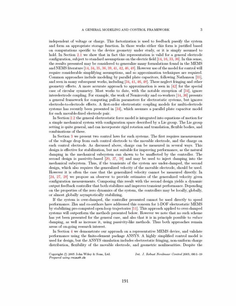
191

192

193
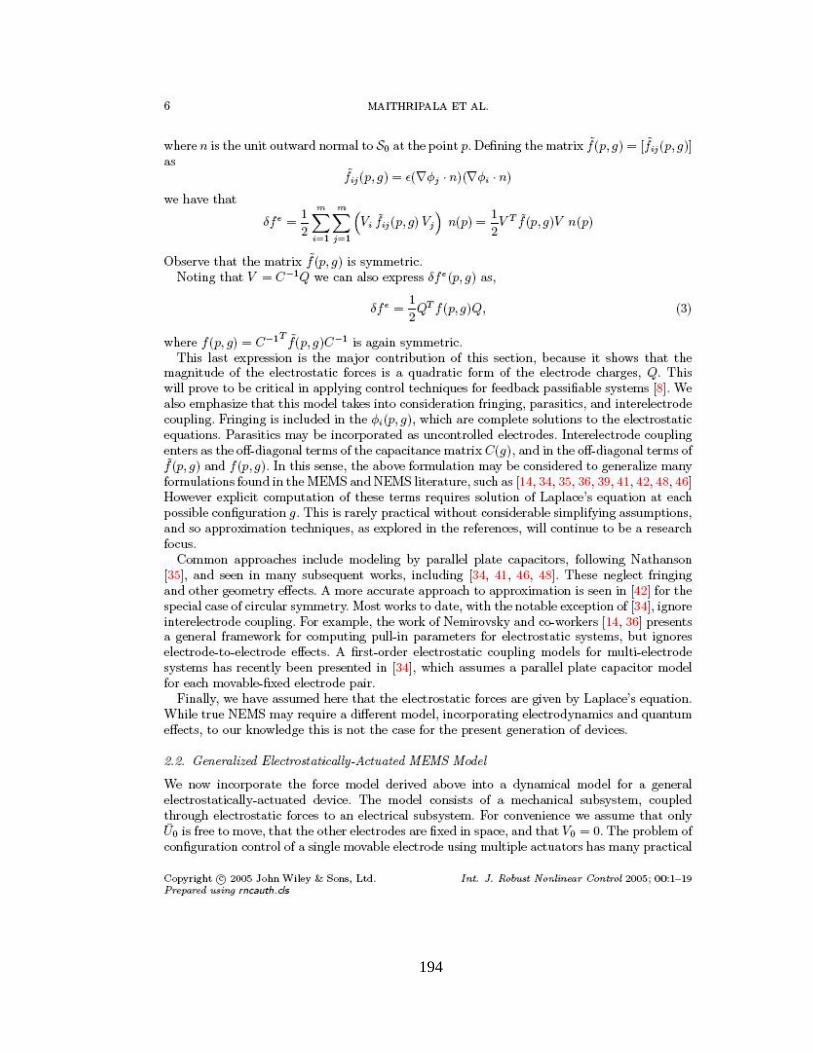
194

195

196

197

198

199

200

201
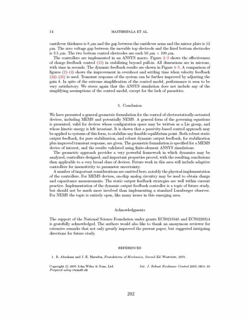
202

203
204
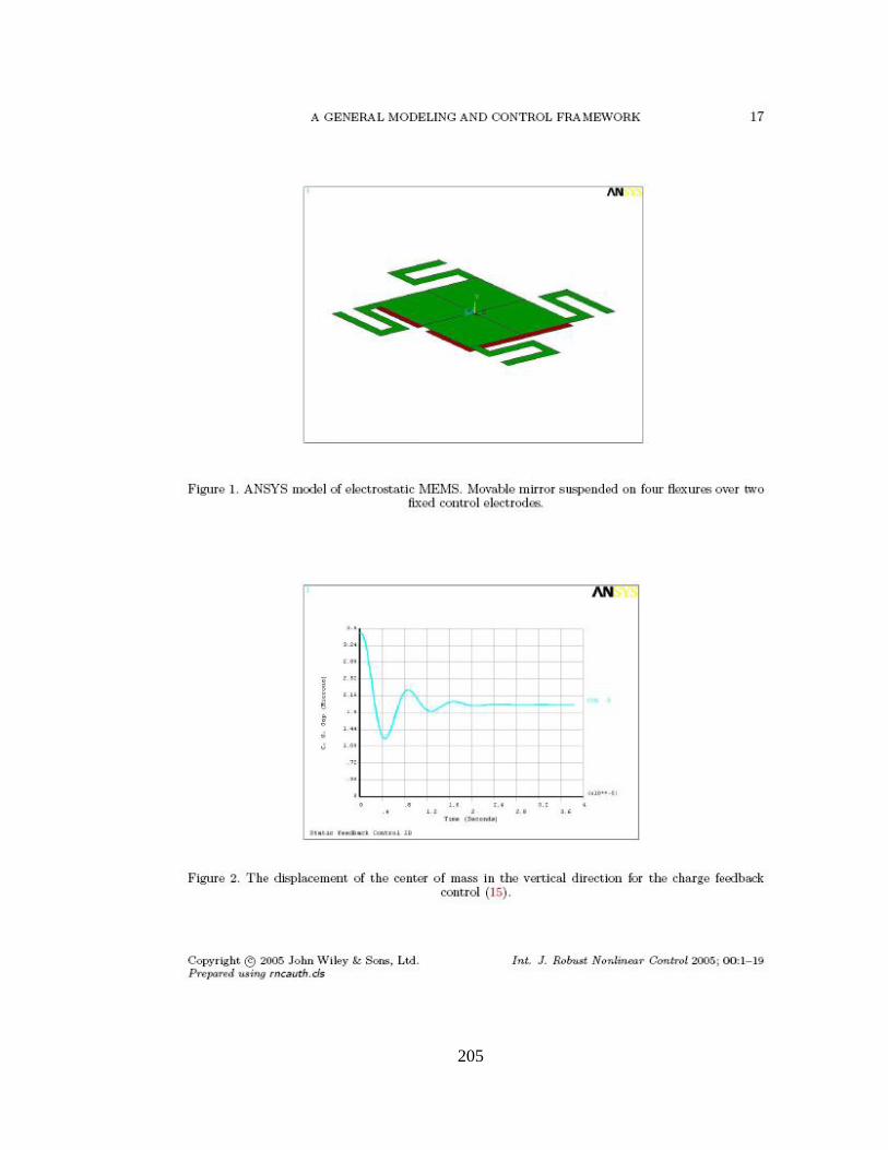
205

206

207

208

209
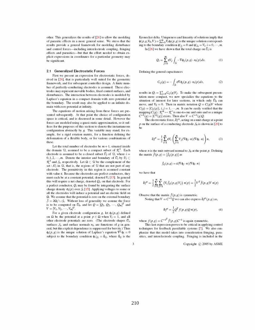
210
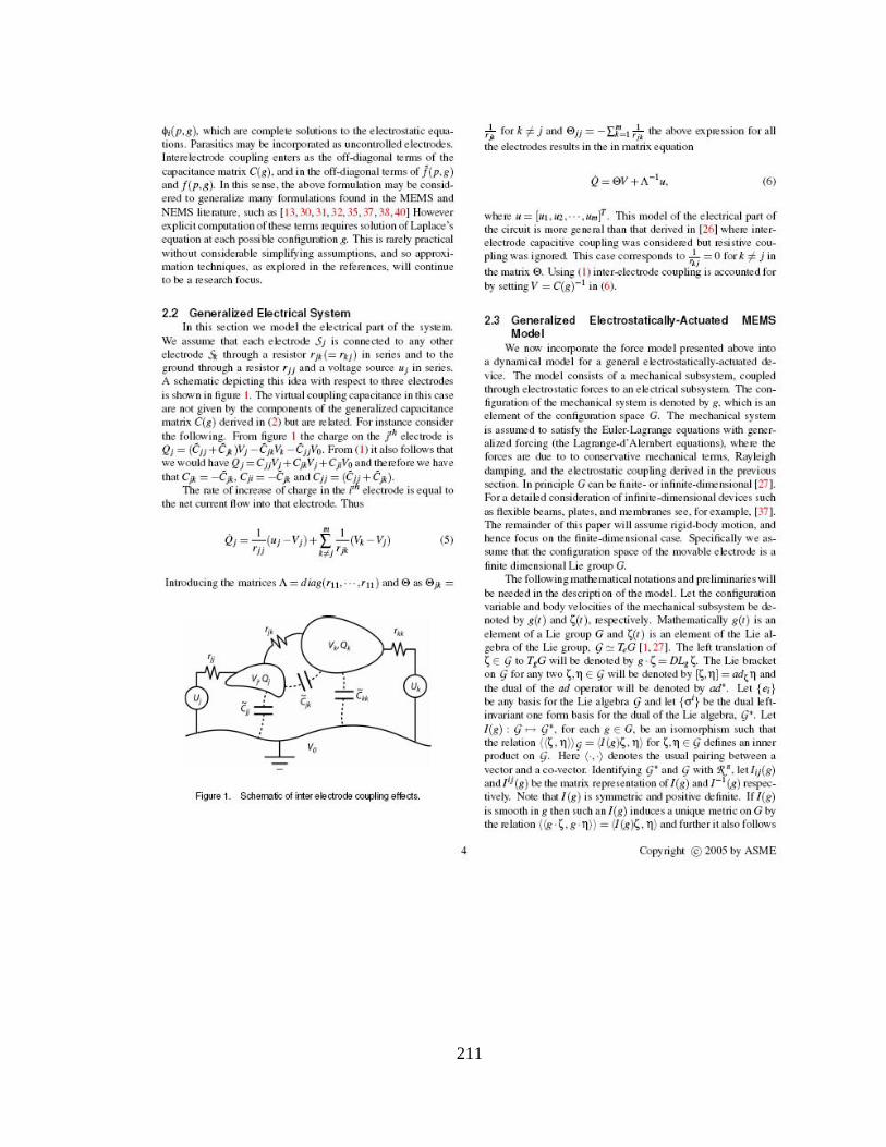
211

212

213
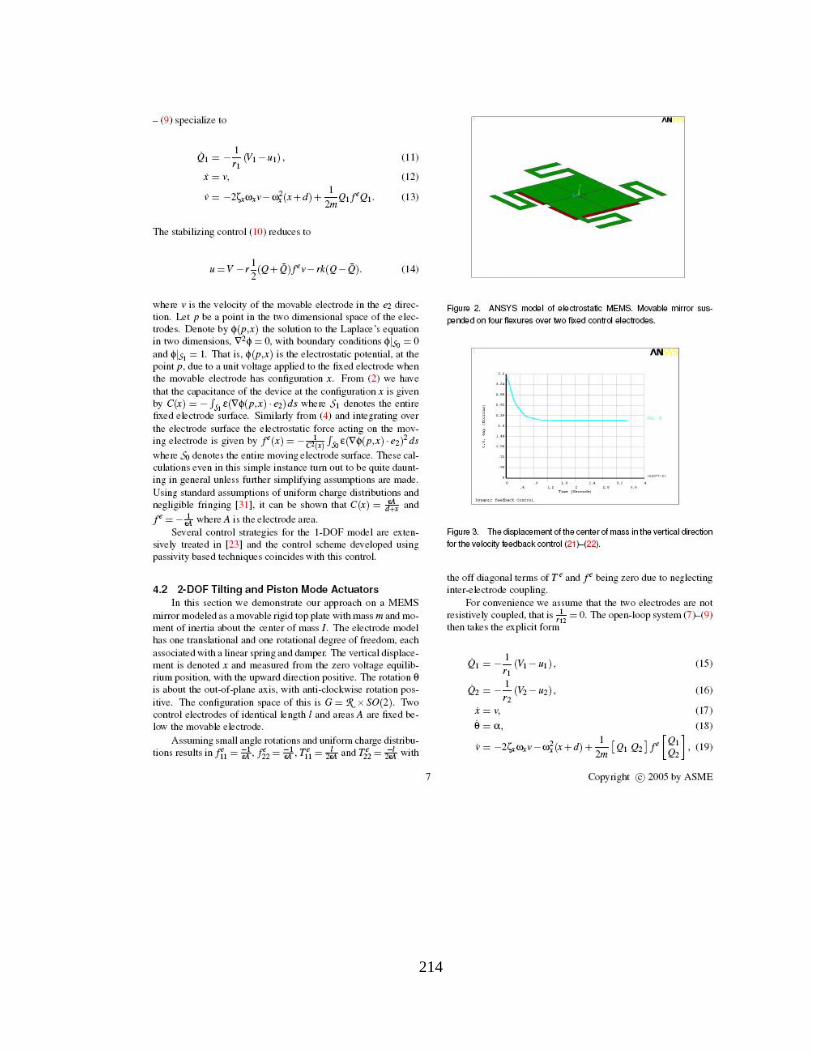
214

215
216
217

PERMISSION TO COPY
In presenting this thesis in partial fulfillment of the requirements for a master’s
degree at Texas Tech University or Texas Tech University Health Sciences Center, I
agree that the Library and my major department shall make it freely available for research
purposes. Permission to copy this thesis for scholarly purposes may be granted by the
Director of the Library or my major professor. It is understood that any copying or
publication of this thesis for financial gain shall not be allowed without my further
written permission and that any user may be liable for copyright infringement.
Agree (Permission is granted.)
_____Balasaheb D. Kawade________________________ __11/23/2005______ Student Signature Date Disagree (Permission is not granted.) _______________________________________________ _________________ Student Signature Date
218