Electrostatic Graphene Loudspeaker
15
Electrostatic Graphene Loudspeaker Qin Zhou and A. Zettl a) Center of Integrated Nanomechanical Systems, University of California at Berkeley, Berkeley, California 94720, USA Department of Physics, University of California at Berkeley, Berkeley, California 94720, USA Materials Sciences Division, Lawrence Berkeley National Laboratory, Berkeley, California 94720, USA Graphene has extremely low mass density and high mechanical strength, key qualities for efficient wide-frequency-response electrostatic audio speaker design. Low mass ensures good high frequency response, while high strength allows for relatively large free-standing diaphragms necessary for effective low frequency response. Here we report on construction and testing of a miniaturized graphene-based electrostatic audio transducer. The speaker/earphone is straightforward in design and operation and has excellent frequency response across the entire audio frequency range (20HZ – 20kHz), with performance matching or surpassing commercially available audio earphones. a) Electronic mail: [email protected]
Transcript of Electrostatic Graphene Loudspeaker
Electrostatic Graphene Loudspeaker
Qin Zhou and A. Zettla)
Center of Integrated Nanomechanical Systems, University of California at Berkeley,
Berkeley, California 94720, USA
Department of Physics, University of California at Berkeley, Berkeley, California 94720,
USA
Materials Sciences Division, Lawrence Berkeley National Laboratory, Berkeley, California
94720, USA
Graphene has extremely low mass density and high mechanical strength, key qualities
for efficient wide-frequency-response electrostatic audio speaker design. Low mass
ensures good high frequency response, while high strength allows for relatively large
free-standing diaphragms necessary for effective low frequency response. Here we report
on construction and testing of a miniaturized graphene-based electrostatic audio
transducer. The speaker/earphone is straightforward in design and operation and has
excellent frequency response across the entire audio frequency range (20HZ – 20kHz),
with performance matching or surpassing commercially available audio earphones.
a)
Electronic mail: [email protected]
2
Efficient audio sound transduction has a history dating back millions of years1. Primitive
insect singers generate loud and pure-tone sound with high efficiency by exciting resonators
inside their body2. Male crickets generate chirping sounds via stridulation
3, where the scraper
edge of one wing is rubbed against the ribbed edge of the other wing. Advantageous structural
properties of the wings (relatively large, low-mass flexural membranes) allow extremely efficient
muscle-to-sound energy transduction. In a human context, unnatural (i.e. non-voice) sound
production has been explored for millennia, with classic examples being drumheads and whistles
for long-range communications and entertainment4. In modern society, efficient small-scale
audio transduction is ever more important for discrete audio earphones and microphones in
portable or wireless electronic communication devices.
For human audibility, an ideal speaker or earphone should generate a constant sound pressure
level (SPL) from 20 Hz to 20 kHz5,6
, i.e. it should have a flat frequency response. Most speakers
available today reproduce sound via a mechanical diaphragm, which is displaced oscillatorily
during operation. The diaphragm, with inherent mass, restoring force (i.e. spring constant), and
damping, essentially constitutes a simple harmonic oscillator. Unlike most insect or musical
instrument resonators which exhibit lightly-damped sharp frequency response, a wide-band
audio speaker typically requires significant damping to broaden the response. Unfortunately,
“damping engineering” quickly becomes complex and expensive, with inevitable power
inefficiencies.
An alternative approach to response spectrum broadening is to reduce both the mass and spring
constant of the diaphragm so that inherent air damping dominates and flattens the response
peaks. Moreover, with ambient air serving as the dominant damping mechanism, most input
3
energy is converted to a sound wave, which makes such speakers highly power efficient. For
these reasons (more detailed analysis is provided in the Supporting Information), the ideal audio
transduction diaphragm should have small mass and a soft spring constant, and be non-perforated
to efficiently displace the surrounding air. Electrostatically-driven thin- membrane
loudspeakers7 employing an electrically conducting, low-mass diaphragm with significant air
damping have been under development since the 1920’s (the first were made of pig intestine
covered with gold-leaf), but miniaturized electrostatic earphones are still rare. One key reason is
that the per-area air damping coefficient significantly decreases when the size of the diaphragm
falls below the sound wavelength8. Hence, for small speakers a thinner and lower mass density
diaphragm is required to continue the dominance of air damping. Such a diaphragm is difficult
to realize. If conventional materials such as metalized mylar are made too thin, they invariably
fatigue and break.
Graphene is an ideal building material for small, efficient, high-quality broad-band audio
speakers because it satisfies all the above criteria. It is electrically conducting, has extremely
small mass density9, and can be configured to have very small effective spring constant. The
effective spring constant of a thin circular membrane is10
4effk t (1)
where σ is the stress and t is the thickness of the membrane. It is convenient to use per-area
values for modeling the diaphragm vibration (see Su Information) since for a given membrane
the mass per unit area is constant. The equivalent per area spring constant is therefore
2
4effk tk
Area R
(2)
where R is the radius of the circular membrane. We note that the spring constant k scales
proportionally with the thickness of the membrane and inversely with the 2nd
power of the radius
4
of the membrane. The exceptional mechanical strength of graphene11
makes it possible to
construct large and thin suspended diaphragms, which effectively reduces k.
Graphene was previously used to construct a thermoacoustic loudspeaker12-14
. In the
thermoacoustic configuration graphene serves as a stationary heater to alternately heat the
surrounding air thereby producing , via thermal expansion, a time-dependent pressure variation,
i.e. sound wave. The method is especially effective in the ultrasonic region because of
graphene’s small heat capacity (for this reason, carbon nanotube films can also be utilized15-17
).
However, for thermoacoustic speakers operating at audio frequencies, most input energy is
dissipated by heat conduction through the air and does not generate sound12
. For example, the
power efficiency for a graphene thermoacoustic speaker is exceedingly small, decreasing from
~10-6
at 20 kHz to ~10-8
at 3 kHz12,13
. The thermoacoustic approach also suffers from sound
distortion because the heating power is proportional to the square of the input signal and the
transduction is therefore intrinsically non-linear15
.
We here describe an electrostatically driven, high-efficiency, mechanically vibrating graphene-
diaphragm based audio speaker. Even without optimization, the speaker is able to produce
excellent frequency response across the whole audible region (20 Hz~20 KHz), comparable or
superior to performance of conventional-design commercial counterparts.
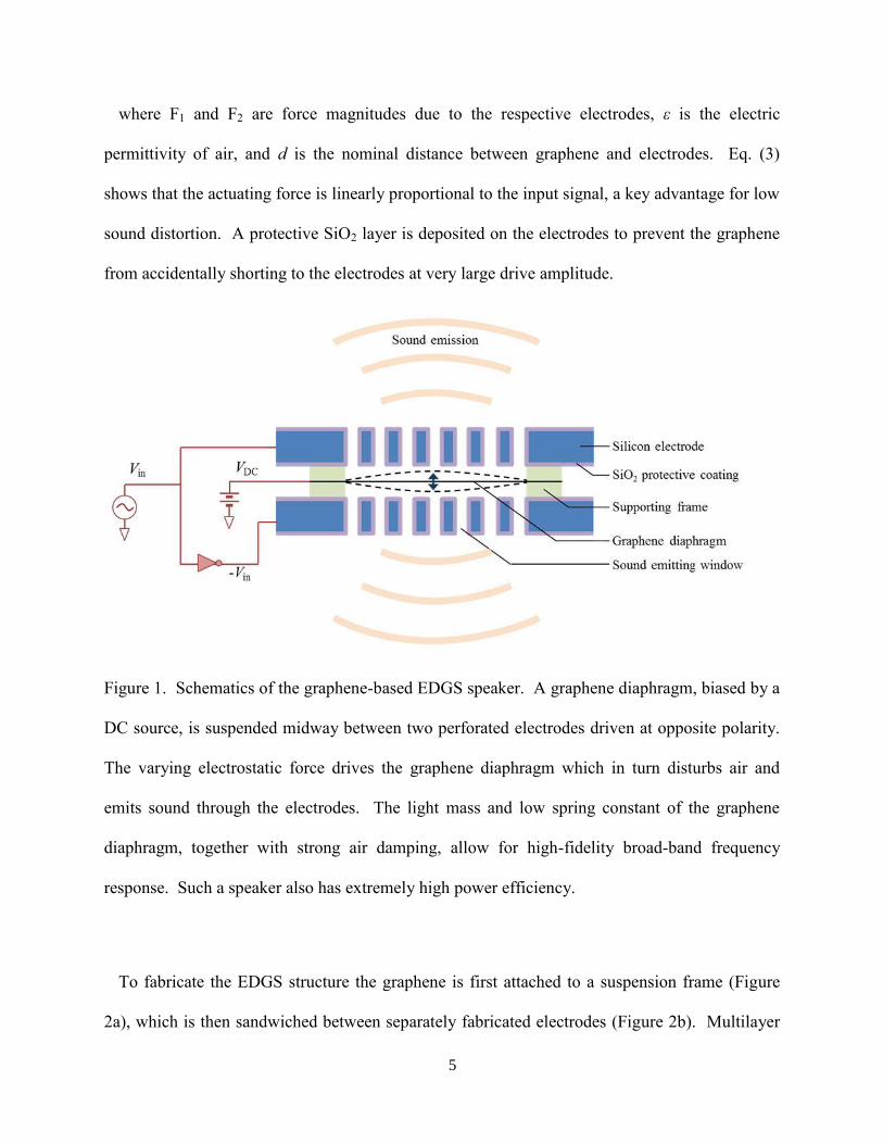
Figure 1 shows schematically the electrostatically driven graphene speaker (EDGS). A
multilayer graphene membrane is suspended midway between two actuating perforated
electrodes. The graphene is DC biased at VDC. With no input signal, the electrostatic forces
from the upper and lower electrodes balance. When the two driving electrodes are driven with
opposite polarity at Vin, the total electrostatic force applied on graphene is (per unit area)
2 2
1 2 2 2 22 2
DCDC in DC in in
VF F F V V V V V
d d d
(3)
5
where F1 and F2 are force magnitudes due to the respective electrodes, ε is the electric
permittivity of air, and d is the nominal distance between graphene and electrodes. Eq. (3)
shows that the actuating force is linearly proportional to the input signal, a key advantage for low
sound distortion. A protective SiO2 layer is deposited on the electrodes to prevent the graphene
from accidentally shorting to the electrodes at very large drive amplitude.
Figure 1. Schematics of the graphene-based EDGS speaker. A graphene diaphragm, biased by a
DC source, is suspended midway between two perforated electrodes driven at opposite polarity.
The varying electrostatic force drives the graphene diaphragm which in turn disturbs air and
emits sound through the electrodes. The light mass and low spring constant of the graphene
diaphragm, together with strong air damping, allow for high-fidelity broad-band frequency
response. Such a speaker also has extremely high power efficiency.
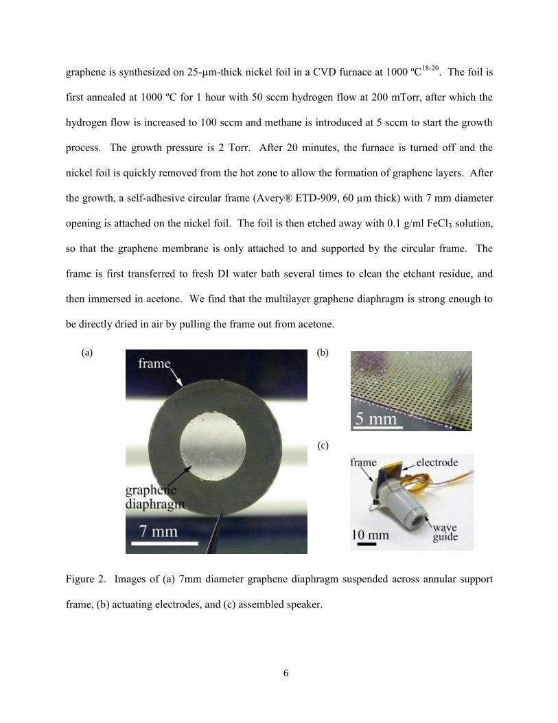
To fabricate the EDGS structure the graphene is first attached to a suspension frame (Figure
2a), which is then sandwiched between separately fabricated electrodes (Figure 2b). Multilayer
6
graphene is synthesized on 25-µm-thick nickel foil in a CVD furnace at 1000 ºC18-20
. The foil is
first annealed at 1000 ºC for 1 hour with 50 sccm hydrogen flow at 200 mTorr, after which the
hydrogen flow is increased to 100 sccm and methane is introduced at 5 sccm to start the growth
process. The growth pressure is 2 Torr. After 20 minutes, the furnace is turned off and the
nickel foil is quickly removed from the hot zone to allow the formation of graphene layers. After
the growth, a self-adhesive circular frame (Avery® ETD-909, 60 µm thick) with 7 mm diameter
opening is attached on the nickel foil. The foil is then etched away with 0.1 g/ml FeCl3 solution,
so that the graphene membrane is only attached to and supported by the circular frame. The
frame is first transferred to fresh DI water bath several times to clean the etchant residue, and
then immersed in acetone. We find that the multilayer graphene diaphragm is strong enough to
be directly dried in air by pulling the frame out from acetone.
Figure 2. Images of (a) 7mm diameter graphene diaphragm suspended across annular support
frame, (b) actuating electrodes, and (c) assembled speaker.
(a) (b)
(c)
7
The thickness of the free-standing graphene diaphragm is determined by light transmission
measurement to be ~30 nm (22%~25% transmission). The electrical contact to the graphene
diaphragm is made by attaching a 20-µm-diameter gold wire to the portion of graphene lying on
the supporting frame. Another circular frame is attached to the original frame from the opposite
side (so that the graphene diaphragm is sandwiched between them) to fix the gold wire. The
frames also serve as spacers between graphene and the electrodes in the speaker assembly. The
gap distance can be increased by stacking multiple (empty) frames on each other. For the results
presented here we use two frames on each side of the graphene, which gives a gap distance d =
120 µm.
The electrodes are constructed from silicon (525 µm thick, resistivity 10 Ohm·cm, test grade).
A photolithography and deep-reactive-ion-etching step are used to construct through-wafer
square holes of 250 µm wide as sound emitting windows. A 500 nm protective wet thermal
oxide layer is then grown on the wafer at 1050 ºC (Figure 2b). The wafer is then diced as
electrodes. Dicing the wafer also exposes the silicon so that electric connections are made by
attaching conductive wires to the edges of the electrodes with silver paste.
For prototype demonstration, two electrodes and one graphene diaphragm are simply
sandwiched together and held by a spring clip. In another implementation, a 7 mm inner-
diameter pipe, serving as a wave guide, is perpendicularly attached to the surface of the
electrodes to facilitate sound coupling between the speaker and a listener’s ear (Figure 2c). This
improves far-field efficiency for a small speaker operating at wavelength larger than the
diaphragm size.
8
We now describe performance tests for the EDGS speaker. VDC=100 V is used to bias the
device, and the input sound signal is introduced from a signal generator or from a commercial
laptop or digital music player. The maximum amplitude of the input signal Vin used in the test is
10V. The operation current is usually a few nano-amps, indicating very low power consumption
(<<1 µW) and high power efficiency. In fact, the power efficiency of an electrostatic speaker
can be exceedingly high (close to 1) because the power dissipation path is almost pure air
damping7, which converts the mechanical vibration of diaphragm to sound. Magnetic coil type
earphones (the type used today for virtually all earphone applications) typically have efficiencies
<0.1.
The sound generated by the graphene speaker is easily audible by the human ear. The fidelity
is qualitatively excellent when listening to music. To quantitatively characterize the speaker, the
frequency response curve is measured from 20 Hz to 20 kHz and compared to a commercial
earphone of similar size (Sennheiser® MX-400). The sound card in a laptop computer
(SoundMAX® Integrated Digital HD Audio) is used to generate equal-amplitude sine waves, and
a commercial condenser microphone (SONY®
ICD-SX700) is used to measure the sound
pressure level (SPL) at different frequencies. The software is Room EQ Wizard.
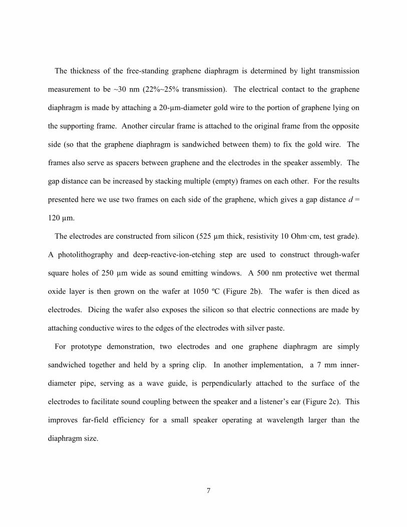
Figure 3 shows the sound pressure level over the relevant audio frequency range for the EDGS
speaker (Figure 3a), the Sennheiser® MX-400 (Figure 3b), and a miniature thermoacoustic
speaker (Figure 3c, adapted from Ref. 13). The graphene speaker, with almost no specialized
acoustic design, performs comparably to a high quality commercial headset. Moreover, the high-
frequency performance of the EDGS (Figure 3a) is markedly better than that for the MX-400
thanks to the extremely low-mass diaphragm. In the low frequency region, the EDGS and MX-
400 response curves both bend downward, largely due to limited capability of the sensing
9
microphone and restricted coupling between the speaker and microphone. Even so, the low-
frequency performance of the EDGS speaker is markedly superior to that predicted for a
thermoacoustic speaker (dashed line, Figure 3c)). At very high frequencies (>10kHz), the
thermoacoustic speaker maintains its excellent high frequency response, but, as mentioned
above, the power efficiency is at least six orders of magnitude lower than that for the EDGS,
which makes it impractical for most portable applications.
Figure 3. Frequency response of various miniature audio speakers. a) Graphene diaphragm
EDGS speaker (this work); b) Commercially available Sennheiser®
MX-400 magnetic coil
speaker; c) Thermoacoustic speaker. The points in panel c) are experimental data from ref. 13,
10
while the solid red line is the theoretically predicted behavior for an ideal thermoacoustic
speaker. The EDGS speaker performs noticeably better than the commercial voice-coil speaker
at high frequencies, both in terms of maintaining high response and avoiding sharp resonances
(the slow oscillations in the EDGES curve are due to sound wave interference in the space
between the speaker and microphone and they depend on the relative position of the speaker and
microphone, but the main trend is consistent). In the low frequency region, both EDGES and the
MX-400 perform well, while the thermoacoustic response falls precipitously already below
15kHz. The decrease in the response curves in a) and b) at very low frequency are largely due to
limited capability of the microphone and the inefficient coupling between the speaker and
microphone.
The speaker-to-microphone performance test has limited accuracy, because the measured
response curve is for the whole system - from the sound card to amplifier, to speaker, to
microphone, and finally back to sound card. Every transduction introduces some distortion in
the measurement. For example, the response is sensitive to the relative position between the
speaker and the microphone. Since the focus of this letter is not the detailed acoustic design of a
complete sound system but rather the capability of the EDGS graphene diaphragm, we employ
laser Doppler velocimetry (LDV) to directly measure the mechanical response limits of the
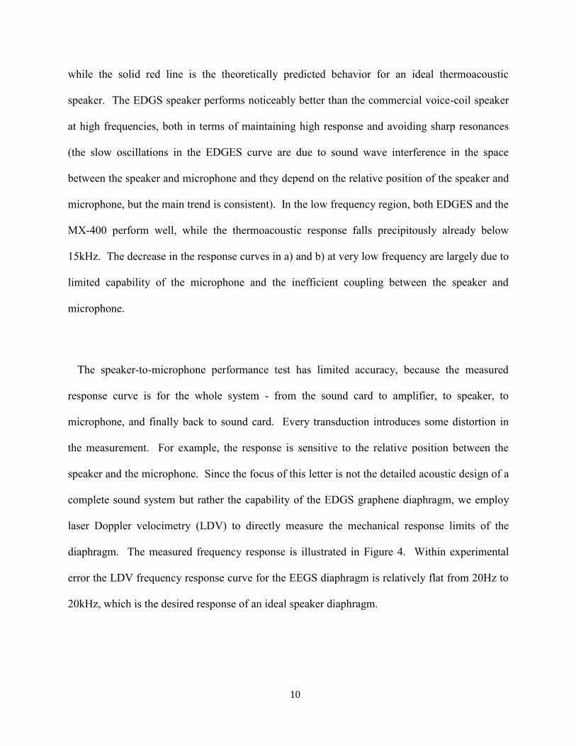
diaphragm. The measured frequency response is illustrated in Figure 4. Within experimental
error the LDV frequency response curve for the EEGS diaphragm is relatively flat from 20Hz to
20kHz, which is the desired response of an ideal speaker diaphragm.
11
Figure 4: Vibration velocity of graphene diaphragm in EDGS v.s. frequency, measured by Laser
Doppler Velocimetry (LDV). Such a measurment is useful because it eliminates extrinsic effects
(e.g. acoustic structural design, sound card, microphone response), and represents the “pure”
response of the graphene diaphragm itself. Within the error limit of the LDV setup, the response
curve appears to be quite flat, indicating that graphene serves as an ideal key component for
loudspeakers.
In summary we have demonstrated a robust speaker built from multi-layered graphene
diaphragm. The diaphragm is driven electrostatically and reproduces sound with high fidelity.
The CVD grown graphene on nickel foil is straightforward and the technique can be easily
scaled to construct larger speakers by arraying the graphene diaphragm. The configuration
described in this letter could also serve as a microphone. The microphone should also have
outstanding response characteristics due to the graphene’s ultra-low mass and the excellent
coupling to ambient air.
12
This work was supported in part by the Director, Office of Energy Research, Office of Basic
Energy Sciences, Materials Sciences and Engineering Division, of the U.S. Department of
Energy under Contract No. DE-AC02-05CH11231, which provided for graphene growth and
characterization; by the Office of Naval Research under grant No. N00014-09-1066, which
provided for graphene transfer and electrode manufacture, and by the National Science
Foundation under Grant No. EEC-083819, which provided for design, construction, and testing
of the device. The authors thank Yung-Kan Chen and Prof. David Bogy for assistance with LDV
measurements.
13
APPENDIX: Modeling a loudspeaker using harmonic oscillator.
To examine why the ideal diaphragm for speakers should have small mass and spring constant,
we model the diaphragm as a 2nd
order spring-damping-mass system, where the mass comes
from the diaphragm (as well as the actuating element if it is vibrating together with the
diaphragm, which is often true for most speakers where the force-generating coil is directly
attached to the diaphragm), the damping force comes from the air, and the spring represents the
restoring force that brings the diaphragm to the balanced position.
The equation that describes the movement of the diaphragm is given by
mx x kx F (S1)
where m is the mass, is the damping coefficient, k is the spring constant, and F is the driving
force applied on the diaphragm. When driving by a sinuous signal at frequency ω, the vibration
amplitude is
1
Fx
i k i m
. (S2)
Here the vibration amplitude is represented in terms of velocity rather than displacement,
because SPL is directly determined by the velocity amplitude of air:
SPL c x
(S3)
where c is the sound velocity and ρ is the mass density of air. From Eq. (S2), we find that
large k results in poor low frequency response (the ω-1
term in denominator), while large m
results in poor high frequency response (the ω term in denominator). As a result, to maintain
constant SPL across the whole frequency region, the spring constant k and the mass of the
diaphragm m should both be significantly smaller than the air damping coefficient (strictly
14
speaking, the criteria should be 1 ,?max mink m
, where ωmax and ωmin represent the
upper and lower bound of the interested frequency region).
15
REFERENCES
1 J.J. Gu, F. Montealegre-Z, D. Robert, M.S. Engel, G.X. Qiao, and D. Ren, Proc. Natl. Acad. Sci.
U.S.A. 109 (10), 3868 (2012). 2 HC Bennet-Clark, J. Exp. Bio. 202 (23), 3347 (1999).
3 HC Bennet-Clark, J. Exp. Bio. 52 (3), 619 (1970).
4 C. Sachs, The history of musical instruments. (Courier Dover Publications, 2006).
5 R. J. Pumphrey, Nature 166 (4222), 571 (1950).
6 B. Masterton, H. Heffner, and R. Ravizza, J. Acoust. Soc. Am. 45 (4), 966 (1969).
7 PJ Walker, Wireless World 61, 208 (1955).
8 Samuel Temkin, Elements of acoustics. (Wiley, New York, 1981).
9 J.S. Bunch, A.M. Van der Zande, S.S. Verbridge, I.W. Frank, D.M. Tanenbaum, J.M. Parpia, H.G.
Craighead, and P.L. McEuen, Science 315 (5811), 490 (2007). 10
G.M. Rebeiz, RF MEMS: Theory, Design, and Technology. (John Wiley & Sons, 2003). 11
C. Lee, X. Wei, J.W. Kysar, and J. Hone, Science 321 (5887), 385 (2008). 12
H. Tian, T.L. Ren, D. Xie, Y.F. Wang, C.J. Zhou, T.T. Feng, D. Fu, Y. Yang, P.G. Peng, and L.G.
Wang, ACS Nano 5 (6), 4878 (2011). 13
H. Tian, D. Xie, Y. Yang, T.L. Ren, Y.F. Wang, C.J. Zhou, P.G. Peng, L.G. Wang, and L.T. Liu,
Nanoscale 4 (7), 2272 (2012). 14
J.W. Suk, K. Kirk, Y. Hao, N.A. Hall, and R.S. Ruoff, Adv. Mater., DOI: 10.1002/adma.201201782
(2012). 15
L. Xiao, Z. Chen, C. Feng, L. Liu, Z.Q. Bai, Y. Wang, L. Qian, Y. Zhang, Q. Li, and K. Jiang, Nano
Lett. 8 (12), 4539 (2008). 16
Timmermans, M. Pudas, and B. Aitchison, ACS Nano 5 (4), 3214 (2011). 17
A.E. Aliev, M.D. Lima, S. Fang, and R.H. Baughman, Nano Lett. 10 (7), 2374 (2010). 18
K.S. Kim, Y. Zhao, H. Jang, S.Y. Lee, J.M. Kim, J.H. Ahn, P. Kim, J.Y. Choi, and B.H. Hong,
Nature 457 (7230), 706 (2009). 19
FJ Derbyshire and DL Trimm, Carbon 13 (3), 189 (1975). 20
A. Reina, X. Jia, J. Ho, D. Nezich, H. Son, V. Bulovic, M.S. Dresselhaus, and J. Kong, Nano Lett. 9
(1), 30 (2008).