
Electrospun linear polyethyleneimine scaffolds for...
10
Electrospun linear polyethyleneimine scaffolds for cell growth Nadia Khanam a , Carole Mikoryak b , Rockford K. Draper a,b , Kenneth J. Balkus Jr. a, * a Department of Chemistry, University of Texas at Dallas, Richardson, TX 75083-0688, USA b Department of Molecular and Cell Biology, University of Texas at Dallas, Richardson, TX 75083-0688, USA Received 12 February 2007; received in revised form 16 May 2007; accepted 11 June 2007 Available online 1 July 2007 Abstract Unique biocompatible scaffolds were produced by electrospinning cross-linked linear polyethyleneimine (PEI) with succinic anhydride and 1,4-butanediol diglycidyl ether. Nonwoven mats of PEI fibers in the range of 1600–687 nm were evaluated as interaction scaffolds for normal human fibroblast (NHF) cells. The electrospun scaffolds were characterized by Fourier transform infrared spectroscopy and ultraviolet–visible spectroscopy. The growth of the NHF cells was followed by scanning electron microscopy as well as optical and fluo- rescence microscopies. Cell viability was evaluated by staining with propidium iodide for dead cells and fluorescein diacetate for live cells. Immunofluorescence with fixed cells on the scaffolds was examined by staining the endoplasmic reticulum with rabbit anti-GRP 78/Alexa 488 goat anti-rabbit and staining the nuclei with 4 0 -6 0 -diamidino-2-phenylindole. Fluorescence studies confirmed that NHF cells attached and spread throughout the cross-linked linear polyethyleneimine scaffold. The attachment and spreading of cells suggests that electro- spun linear polyethyleneimine scaffolds support growth of normal human fibroblasts cells. Thus, these biomaterial scaffolds may be use- ful in tissue engineering. Ó 2007 Acta Materialia Inc. Published by Elsevier Ltd. All rights reserved. Keywords: Scaffold; Polyethyleneimine; Fibroblast; Electrospinning 1. Introduction Millions of therapeutic procedures are performed each year to replace tissue lost to trauma or disease. These approaches can be divided into three categories: (1) syn- thetic prostheses, (2) drug delivery and (3) organ transplan- tation [1]. The search for alternative therapies has been the underlying motivation of tissue engineering [1]. The goal is an alternative approach to the repair and regeneration of damaged human tissue which avoids the need for a perma- nent implant [2,3]. One area in which tissue regeneration has been successful is in skin replacement. Every year, thousands of people suffer from extensive and severe burns. The common practice for small burn wounds has been to cover the area with a skin graft, usually the patient’s own skin which minimizes complications such as tissue rejec- tion. However, if the burned area is large, finding donor skin to cover the wounds is difficult. Therefore, tissue engi- neering offers new hope. One way to address these prob- lems is to create natural skin or synthetic skin substitutes through tissue engineering [4]. The human body consists of organs and tissues orga- nized in three-dimensional (3-D) structures. The first goal of this study is to design and fabricate scaffold in such a way that it can create and maintain a space for tissue devel- opment. It is well known that the extracellular environment influences many aspects of cell behavior, morphology, functionality and cell–cell interactions [5]. The extracellular matrix (ECM) has physical structural features ranging from nanometer scale to micrometer scale. The ECM is also cell specific and provides a protective outer layer for cells. In general, scaffolds are porous, biodegradable and or biocompatible structures which are designed to mimic the extracellular matrix, acting as a physical support struc- ture to give the cells the necessary shape. These scaffolds can then be transplanted in vivo [6]. These 3-D scaffolds 1742-7061/$ - see front matter Ó 2007 Acta Materialia Inc. Published by Elsevier Ltd. All rights reserved. doi:10.1016/j.actbio.2007.06.005 * Corresponding author. Tel.: +1 972 883 2659; fax: +1 972 883 2925. E-mail address: [email protected] (K.J. Balkus Jr.). Acta Biomaterialia 3 (2007) 1050–1059 www.elsevier.com/locate/actabiomat
Transcript of Electrospun linear polyethyleneimine scaffolds for...

Acta Biomaterialia 3 (2007) 1050–1059
www.elsevier.com/locate/actabiomat
Electrospun linear polyethyleneimine scaffolds for cell growth
Nadia Khanam a, Carole Mikoryak b, Rockford K. Draper a,b, Kenneth J. Balkus Jr. a,*
a Department of Chemistry, University of Texas at Dallas, Richardson, TX 75083-0688, USAb Department of Molecular and Cell Biology, University of Texas at Dallas, Richardson, TX 75083-0688, USA
Received 12 February 2007; received in revised form 16 May 2007; accepted 11 June 2007Available online 1 July 2007
Abstract
Unique biocompatible scaffolds were produced by electrospinning cross-linked linear polyethyleneimine (PEI) with succinic anhydrideand 1,4-butanediol diglycidyl ether. Nonwoven mats of PEI fibers in the range of 1600–687 nm were evaluated as interaction scaffolds fornormal human fibroblast (NHF) cells. The electrospun scaffolds were characterized by Fourier transform infrared spectroscopy andultraviolet–visible spectroscopy. The growth of the NHF cells was followed by scanning electron microscopy as well as optical and fluo-rescence microscopies. Cell viability was evaluated by staining with propidium iodide for dead cells and fluorescein diacetate for live cells.Immunofluorescence with fixed cells on the scaffolds was examined by staining the endoplasmic reticulum with rabbit anti-GRP 78/Alexa488 goat anti-rabbit and staining the nuclei with 4 0-6 0-diamidino-2-phenylindole. Fluorescence studies confirmed that NHF cells attachedand spread throughout the cross-linked linear polyethyleneimine scaffold. The attachment and spreading of cells suggests that electro-spun linear polyethyleneimine scaffolds support growth of normal human fibroblasts cells. Thus, these biomaterial scaffolds may be use-ful in tissue engineering.� 2007 Acta Materialia Inc. Published by Elsevier Ltd. All rights reserved.
Keywords: Scaffold; Polyethyleneimine; Fibroblast; Electrospinning
1. Introduction
Millions of therapeutic procedures are performed eachyear to replace tissue lost to trauma or disease. Theseapproaches can be divided into three categories: (1) syn-thetic prostheses, (2) drug delivery and (3) organ transplan-tation [1]. The search for alternative therapies has been theunderlying motivation of tissue engineering [1]. The goal isan alternative approach to the repair and regeneration ofdamaged human tissue which avoids the need for a perma-nent implant [2,3]. One area in which tissue regenerationhas been successful is in skin replacement. Every year,thousands of people suffer from extensive and severe burns.The common practice for small burn wounds has been tocover the area with a skin graft, usually the patient’s ownskin which minimizes complications such as tissue rejec-
1742-7061/$ - see front matter � 2007 Acta Materialia Inc. Published by Else
doi:10.1016/j.actbio.2007.06.005
* Corresponding author. Tel.: +1 972 883 2659; fax: +1 972 883 2925.E-mail address: [email protected] (K.J. Balkus Jr.).
tion. However, if the burned area is large, finding donorskin to cover the wounds is difficult. Therefore, tissue engi-neering offers new hope. One way to address these prob-lems is to create natural skin or synthetic skin substitutesthrough tissue engineering [4].
The human body consists of organs and tissues orga-nized in three-dimensional (3-D) structures. The first goalof this study is to design and fabricate scaffold in such away that it can create and maintain a space for tissue devel-opment. It is well known that the extracellular environmentinfluences many aspects of cell behavior, morphology,functionality and cell–cell interactions [5]. The extracellularmatrix (ECM) has physical structural features rangingfrom nanometer scale to micrometer scale. The ECM isalso cell specific and provides a protective outer layer forcells. In general, scaffolds are porous, biodegradable andor biocompatible structures which are designed to mimicthe extracellular matrix, acting as a physical support struc-ture to give the cells the necessary shape. These scaffoldscan then be transplanted in vivo [6]. These 3-D scaffolds
vier Ltd. All rights reserved.
N. Khanam et al. / Acta Biomaterialia 3 (2007) 1050–1059 1051
will provide an actual physical structure for directing thegrowth of new replacement cells. With time, the scaffoldshould disintegrate leaving the body with its natural tis-sues. The 3-D scaffold should closely mimic the nativeextracellular matrix than the conventional method of grow-ing tissues on a 2-D Petri dish surface.
Electrospinning has been used extensively as a leadingtechnology for generation of 3-D scaffolds [7,8]. Variousnatural biopolymers, such as collagen, chitosan and elas-tin–collagen based materials, have been used [9–13]. Vari-ous synthetic biodegradable polymers and naturalproteins have also been used as scaffolds for cell support[14–16]. Electrospinning is a simple and scalable methodof producing fibers with diameters ranging from severalmicrons to less than 100 nm [17–19]. The small pore sizebetween electrospun fibers is also an attractive feature forbiomimetic materials [20]. Electrospinning involves apply-ing a high potential to a polymer solution. Once a polymergel overcomes its surface tension, a thin jet of solution,referred to as a Taylor cone, will erupt from the surface[17,21]. This jet follows a chaotic pathway and finallydeposits onto a grounded target [22]. There are several cat-egories of variables that influence the electrospun fiberdiameter including polymer solution variables, processvariables and environmental variables. The effects of pro-cessing variables (applied voltage, needle tip to target dis-tance, feed rate of the solution to the capillary tip) andsolution properties such as solvent, viscosity, concentrationand surface tension on controlling the fiber morphologyand diameter have been extensively investigated for a vari-ety of polymeric systems [23,24]. Environmental conditionsalso play a critical role in fiber morphology. Studies haveshown that fibers electrospun from solutions at elevatedtemperatures were more uniform in diameter than thoseprepared at room temperature [25]. Due to the high sur-face-to-volume ratio of electrospun polymer fibers thereare a broad range of applications, including scaffolds in tis-sue engineering, chemical/biological resistant protectiveclothing, filtration, enzyme immobilization, controlleddrug release, membranes and sensors [5,19,26,27]. Polycat-ionic polymers that contain a high density of protonatedprimary, secondary, tertiary and/or quaternary aminesare of interest. Several researchers have reported PEI tobe cytotoxic in many cells [28,29]. Free PEI has beenreported to destabilize outer membranes of Gram-negativebacteria [30–32]. However, PEI in its protonated form hasbeen perhaps the cationic polymer most widely used as agene delivery agent due to its high charge density fromthe protonated amines [33,34]. Scaffolds with an excessiveamount of positive charges are highly toxic in vivo whilelower amounts of cationic charge are favorable [35–37].The second goal of this study was to enhance scaffold bio-compatibility; therefore, linear PEI was electrospun withsuccinic anhydride and 1,4-butanediol diglycidyl ether.Electrospun linear polyethyleneimine scaffolds promotedcell growth by mimicking the biological function of thenative extracellular matrix. Normal human fibroblasts cells
were found to attach and thrive even after 5 days of cellculturing.
2. Materials and methods
2.1. Materials
Succinic anhydride (97%) and 1,4-butanediol diglycidylether (95%) were purchased from Sigma–Aldrich (St.Louis, MO) and used to prepare linear PEI scaffold. Nor-mal human fibroblasts (NHF) were obtained from theAmerican Type Tissue Culture Collection (Manassas,VA). Trypsin–EDTA solution and Dulbecco’s modifiedEagle’s medium (DMEM) were purchased from Irvine Sci-entific Inc. (Santa Ana, CA), fetal bovine calf serum (FBS)was purchased from HyClone (Logan, UT) and bovineserum albumin (BSA) was purchased from Sigma (St.Louis, MO). Fluorescein diacetate (FDA) (98%), propidi-um iodide (PI) (95%) and 4 0-6 0-diamidino-2-phenylindole(DAPI) (98%) were purchased from Sigma. Paraformalde-hyde (95%, Sigma–Aldrich), 4-(2-hydroxyethyl)-1-piperazi-neethanesulfonic acid (HEPES) (99%, Fisher) and sodiumazide (99.5%, Sigma) were also purchased. The penicillinand streptomycin used in cell culture studies were fromSigma (St. Louis, MO). Rabbit anti-Grp78 was purchasedfrom StressGen Biotechnologies Corp. (San Diego, CA),Alexa 488 goat anti-rabbit was purchased from MolecularProbes (Carlsbad, CA) and Fluoromount G was purchasedfrom Fisher.
2.2. Scaffold fabrication
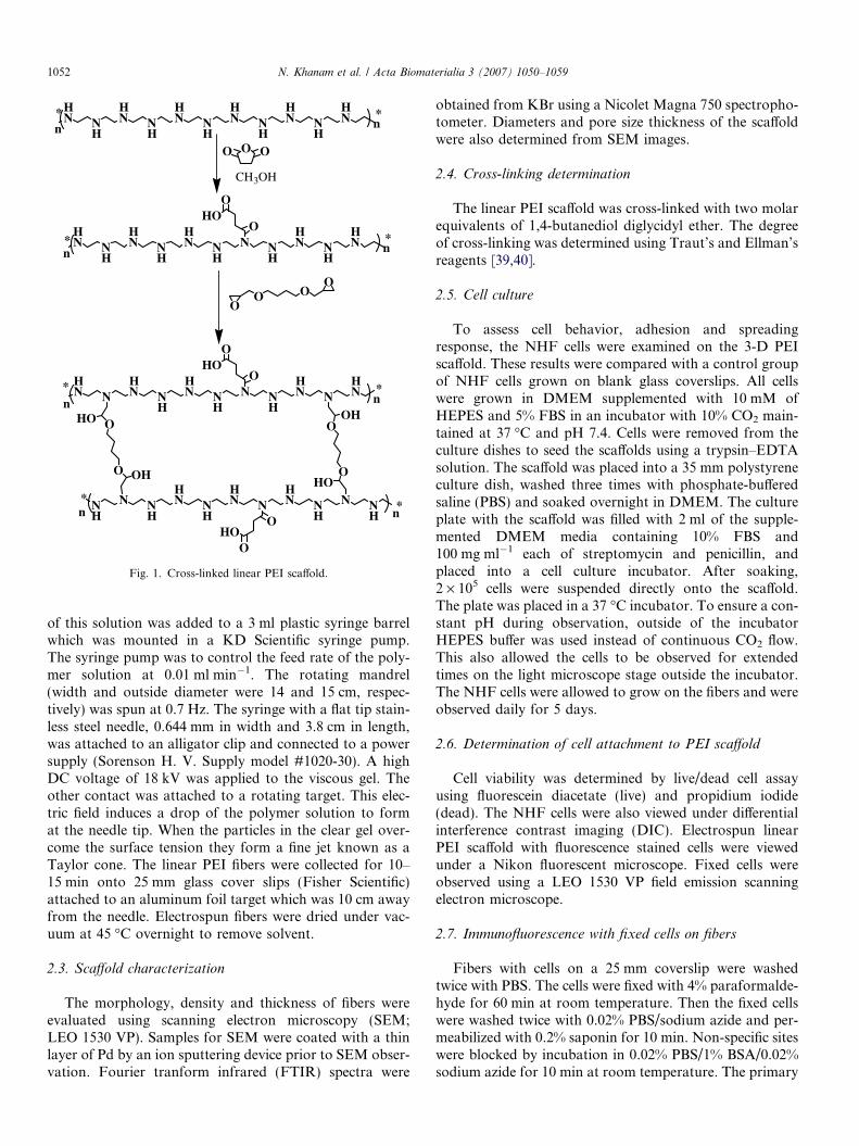
Linear PEI was synthesized from poly(oxazoline) via amodification of a Tanaka et al. procedure [38]. In this pro-cedure, 15 g of poly(oxazoline) (MW of 500,000) was dis-solved in 125 ml of deionized water. Then 190 ml of 12 MHCl was slowly added to the solution, which was stirredfor 5 days at 100 �C. After 24 h of stirring a white precip-itate formed. After 5 days the slurry was cooled and50 ml of a 5 M NaOH solution was added with stirringto give a pH of 14. The white solid was collected by vac-uum filtration and washed with deionized water until thepH of the filtrate was 7. The white solids were recrystallizedfrom 500 ml of hot ethanol. The precipitate was filteredand vacuum dried at 75 �C for 12 h. A semi-transparentwhite solid was obtained (yield �90%, based on a calcu-lated MW of 215,000). Linear PEI (400 mg) was dissolvedin 2 ml of methanol. Then 80 mg of succinic anhydride(SA) was added to the polymer solution and the bath son-icated for 30 min. The clear solution was stirred at roomtemperature in a 10 ml vial to evaporate methanol untilthe viscosity was 1620 cP. Then 0.25 ml of 1,4-butanedioldiglycidyl ether was added to the viscous gel to give amolar ratio of 1 PEI:0.09 SA:0.18 1,4-butanediol diglycidylether. This was stirred for 10 min at room temperature tofurther cross-link the polymer. The general scheme forcross-linking PEI is shown in Fig. 1. Approximately 2 ml
HN N
H
HN N
H
HN N
H
HN N
H
HN N
H
HN
OO O
OO
* *n n
CH3OH
HN N
H
HN N
H
HN N
HN N
H
HN N
H
HN* *
n n
OHO
O
HN N
HN N
H
HN N
HN N
H
HN N
HN
O
OHO
NH
N NH
HN N
H
HN N
HN N
HN N
HO
OHO
O
O
O
O
HO
OH
OH
**
* *n n
n n
HO
OO
Fig. 1. Cross-linked linear PEI scaffold.
1052 N. Khanam et al. / Acta Biomaterialia 3 (2007) 1050–1059
of this solution was added to a 3 ml plastic syringe barrelwhich was mounted in a KD Scientific syringe pump.The syringe pump was to control the feed rate of the poly-mer solution at 0.01 ml min�1. The rotating mandrel(width and outside diameter were 14 and 15 cm, respec-tively) was spun at 0.7 Hz. The syringe with a flat tip stain-less steel needle, 0.644 mm in width and 3.8 cm in length,was attached to an alligator clip and connected to a powersupply (Sorenson H. V. Supply model #1020-30). A highDC voltage of 18 kV was applied to the viscous gel. Theother contact was attached to a rotating target. This elec-tric field induces a drop of the polymer solution to format the needle tip. When the particles in the clear gel over-come the surface tension they form a fine jet known as aTaylor cone. The linear PEI fibers were collected for 10–15 min onto 25 mm glass cover slips (Fisher Scientific)attached to an aluminum foil target which was 10 cm awayfrom the needle. Electrospun fibers were dried under vac-uum at 45 �C overnight to remove solvent.
2.3. Scaffold characterization
The morphology, density and thickness of fibers wereevaluated using scanning electron microscopy (SEM;LEO 1530 VP). Samples for SEM were coated with a thinlayer of Pd by an ion sputtering device prior to SEM obser-vation. Fourier tranform infrared (FTIR) spectra were
obtained from KBr using a Nicolet Magna 750 spectropho-tometer. Diameters and pore size thickness of the scaffoldwere also determined from SEM images.
2.4. Cross-linking determination
The linear PEI scaffold was cross-linked with two molarequivalents of 1,4-butanediol diglycidyl ether. The degreeof cross-linking was determined using Traut’s and Ellman’sreagents [39,40].
2.5. Cell culture
To assess cell behavior, adhesion and spreadingresponse, the NHF cells were examined on the 3-D PEIscaffold. These results were compared with a control groupof NHF cells grown on blank glass coverslips. All cellswere grown in DMEM supplemented with 10 mM ofHEPES and 5% FBS in an incubator with 10% CO2 main-tained at 37 �C and pH 7.4. Cells were removed from theculture dishes to seed the scaffolds using a trypsin–EDTAsolution. The scaffold was placed into a 35 mm polystyreneculture dish, washed three times with phosphate-bufferedsaline (PBS) and soaked overnight in DMEM. The cultureplate with the scaffold was filled with 2 ml of the supple-mented DMEM media containing 10% FBS and100 mg ml�1 each of streptomycin and penicillin, andplaced into a cell culture incubator. After soaking,2 · 105 cells were suspended directly onto the scaffold.The plate was placed in a 37 �C incubator. To ensure a con-stant pH during observation, outside of the incubatorHEPES buffer was used instead of continuous CO2 flow.This also allowed the cells to be observed for extendedtimes on the light microscope stage outside the incubator.The NHF cells were allowed to grow on the fibers and wereobserved daily for 5 days.
2.6. Determination of cell attachment to PEI scaffold
Cell viability was determined by live/dead cell assayusing fluorescein diacetate (live) and propidium iodide(dead). The NHF cells were also viewed under differentialinterference contrast imaging (DIC). Electrospun linearPEI scaffold with fluorescence stained cells were viewedunder a Nikon fluorescent microscope. Fixed cells wereobserved using a LEO 1530 VP field emission scanningelectron microscope.
2.7. Immunofluorescence with fixed cells on fibers
Fibers with cells on a 25 mm coverslip were washedtwice with PBS. The cells were fixed with 4% paraformalde-hyde for 60 min at room temperature. Then the fixed cellswere washed twice with 0.02% PBS/sodium azide and per-meabilized with 0.2% saponin for 10 min. Non-specific siteswere blocked by incubation in 0.02% PBS/1% BSA/0.02%sodium azide for 10 min at room temperature. The primary

Fig. 2. SEM images of electropsun linear PEI scaffold without succinicanhydride and 1,4-butanediol diglycidyl ether: (A) thick fiber mesh beforenormal rat kidney cells seeding and (B) sample after 2 days of incubation(inset from a larger section of B).
N. Khanam et al. / Acta Biomaterialia 3 (2007) 1050–1059 1053
antibody (anti-Grp78, also known as BiP at a 1:100 dilu-tion) was added to the coverslip to completely cover thesurface and allowed to incubate at room temperature for45 min. The coverslip was rinsed three times with 0.02%PBS/sodium azide, and then blocked again with PBS/BSA/sodium azide for 10 min. The secondary antibody(Alexa 488 goat anti-rabbit at a 1:100 dilution) was addedto the coverslip and incubated at room temperature for45 min. The coverslip was rinsed three times with PBS/sodium azide, and then incubated in 2 ml of a DAPI solu-tion of 0.5 ng ml�1 for 15 min. The coverslip was rinsedwith PBS/sodium azide, then with deionized water andmounted onto a glass slide with Fluoromount G.
3. Results and discussion
3.1. Preparation of linear PEI scaffolds
Three-dimensional scaffolds were used to investigatecell–scaffold interactions and cell behavior. There are manyfactors to be considered in developing a scaffold such asporosity, surface properties and chemical composition. Inthis study a novel 3-D PEI scaffold was developed to sup-port growth of NHF cells. To promote interaction with thenegatively charged cell membrane, linear PEI was usedbecause of its cationic charge density [35]. Until now, linearPEI has been used extensively for drug delivery and vectorsin non-viral gene delivery [31]. Our initial studies werebased on both branched and linear PEI. However, attemptsto electrospin branched PEI were not successful. In con-trast, linear PEI was electrospun to give a high surface areato volume scaffold. However, the linear PEI fibers them-selves readily dissolved in PBS, rendering them unsuitableas a 3-D support. To retain the scaffold structure and toprevent dissolution a cross-linking agent, 1,4-diglycidylether, was added. The pH of the cell cultures with thesescaffolds immediately became basic, even after changingthe cell culture medium. This caused the cells to eventuallydie. From cell studies it became apparent that cross-linkingalone was insufficient for maintaining cell viability and thatthe chemical composition needed to be modified to makethe scaffold compatible for cell growth. Polyethyleneiminesare weak bases with pKas of their conjugate acids typicallyaround 7. In order to tune the cationic charge density ofthe scaffold, the linear PEI was treated with succinic anhy-dride. This converts some of the amines to amides, thusdecreasing the overall basicity of the scaffold.
Electrospun linear PEI with 20 wt.% of succinic anhy-dride revealed a porous structure consisting of a 3-D net-work of fibers. The morphological variation of the fibersmay be due to viscosity of the polymer gel and the appliedpotential. The effect of the applied potential on the mor-phology and size of the electrospun fiber mesh was investi-gated. All other electrospinning parameters, including thedistance between the needle tip and the collector, solutionflow rates, and syringe and needle diameters were held con-stant. Linear PEI was electrospun under applied potentials
of 16, 18 and 20 kV over a collection distance of 10 cm.Electrospinning of linear PEI scaffolds was carried out ata viscosity of 1620 cP measured by a Brookfield Viscome-ter. Smooth fibers without the presence of beads wereobtained. The average diameters of the obtained electro-spun fibers were 1143 ± 255 nm (16 kV), 687 ± 71 nm(18 kV) and 462 ± 158 nm (20 kV), as determined fromby SEM from top-down views.
Cell growth was affected by the thickness of the 3-Dscaffold. Fig. 2A shows a dense fiber mat that was usedin early studies. Linear PEI was electrospun with 1,4-butanediol diglycidylether. Under cell media, the fiberdiameter swelled to 2.4 ± 0.5 lm, thus nearly closing thepores. Also the pH of the media became too basic. Onepossible explanation is that organic matter can leach outof the scaffold. This surface morphology did not allowthe cells to penetrate into the inner areas when the cell sus-pension was seeded on the scaffold. A membrane with lessspace between the fibers has a detrimental effect on cellmigration in the cell growth on the surface of the scaffold

1054 N. Khanam et al. / Acta Biomaterialia 3 (2007) 1050–1059
[4]. The cells did not get enough nutrients and oxygen tosurvive under this condition. NHF cells were not able toattach and grow in the scaffold in Fig. 2A. Fig. 2B showsrounded up dead cells throughout the dense scaffold, fur-ther supporting this theory. With a small pore size, the cellswere not able to deposit deep into the scaffold and effectivemass transfer between the cells did not occur.
Electrospinning under higher voltages did not produceuniform fibers. At 20 kV individual fibers have a flattenedappearance (Fig. 3A). This indicates a decrease in the fiberdiameters with increasing applied potential, as seen inFig. 3B. This could be a result of the increase in the trans-port rate of the charged jet from the nozzle by the electro-static force acting on it. The thickness of the fiber mesh wasalso affected by varying the electric potential and deposi-tion time. After 15 min of deposition time at 20 kV the elec-trospun scaffold thickness was 49 lm (Fig. 3B, inset).
Electrospinning can produce PEI fibrous mats with porediameters varying from several microns to several hundredmicrons. At 18 kV the average diameter of the electrospunPEI fibers was 687 ± 71 nm, as shown in Fig. 4A. From atop-down SEM image, the average pore diameter was16.77 ± 9.16 lm, compared with the average NHF celldiameter of 20.3 lm [41]. Thus the spaces between fibersshown in Fig. 4B are ideally sized to allow NHF cells tomigrate within the scaffold. The thickness of the scaffold
Fig. 3. SEM images of electropsun linear PEI scaffolds: (A) fiber meshand (B) fiber diameter (inset is a cross-section of the scaffold) at 20 kV.
Fig. 4. SEM images of electropsun linear PEI scaffolds: (A) fiber mesh(inset fiber diameter) and (B) pore sizes (inset is the cross-section of thescaffold) at 18 kV.
electrospun at 18 kV was 30.94 lm (Fig. 4B, inset) after10 min of deposition.
3.2. Scaffold characterization
The linear PEI scaffold obtained via electrospinningcontains both secondary and tertiary amines, as well as alesser amount of terminal primary amines (Fig. 1). Basedon the stoichiometry, the maximum degree of cross-linkingis 26.7% (see Table 1). Additionally, only 8.1% of the PEIshould be functionalized with succinic anhydride. How-ever, to better evaluate the composition of the fiber sur-faces, the scaffolds were investigated via FTIR. In Fig. 5,a strong peak at 3430 cm�1 is indicative of N–H groups[42]. The C–H stretches were observed at 2919 and2847 cm�1. The C@O peak is at 1729 cm�1 [43]. The amide
Table 1Per cent of primary amines, secondary amines and carboxylates inelectrospun linear PEI scaffold
Chemical functionality Theoretical(mol%)
Experimental(mol%)
PEI/SA/diglycidyl ether (amines) 26.7 25.2PEI/SA/diglycidyl ether (carboxylates) 8.6 3.1PEI/diglycidyl ether (amines) 18.1 17.2

5001000150020002500300035004000
Wavenumber (cm-1)
Tra
nsm
itta
nce
(%) N-H
C-H
Amide IAmide II
C=O
C-H
C-N
Fig. 5. FTIR-ATR of linear PEI/succinic anhydride with 1,4-butanedioldiglycidyl ether scaffold.
N. Khanam et al. / Acta Biomaterialia 3 (2007) 1050–1059 1055
I [42] peak is at 1648 cm�1, and 1552 cm�1 correspondswith the amide II peak. These results are consistent withthe structure in Fig. 1.
3.3. Determination of the degree of cross-linking
A colorimetric determination of reactive amino groupsin the PEI scaffold was determined using Traut’s andEllman’s reagents via ultraviolet–visible spectroscopy[39,40]. The experimentally determined degree of cross-linking of the amines was 25.2%, while the theoretical max-imum was 26.7% (see Table 1 for calculations). Theexposed carboxyl groups in the linear PEI fibers can bequantified via a similar method [40]. The amount of acces-
Fig. 6. Five days of culture: (A) differential interference contrast image (DIC) oof FDA stained live normal human fibroblasts cells; (C) PI stained dead cells
sible carboxylate groups in the electrospun linear PEI scaf-fold was determined to be 39.5% of the theoretical amount,assuming all of the succinic anhydride reacted.
3.4. Cell viability
For skin scaffolds, both surface compatibility and a 3-Dporous structure to support cell attachment and growth areneeded [44]. A cell viability study was used to assess poten-tial cytotoxic cellular interactions by staining the scaffoldwith FDA, PI and DAPI. DAPI forms fluorescent prod-ucts upon binding to DNA in the nucleus. This fluorescentprobe can be used with Alexa 488 and other fluorescentprobes to differentiate organelles in the cell. Fluoresceindiacetate is a non-polar dye which passes through the cellmembrane. Once inside the cell, intracellular esterasescleave the diacetate group to produce a fluorescent greenproduct [44]. Therefore, the product fluorescein accumu-lates in those cells that have intact cell membranes. Cellsthat do not have an intact membrane cannot accumulatefluorescein and do not exhibit green fluorescence. PI is anon-permeant dye which can penetrate the membranes ofdead or dying cells. It intercalates into the major grooveof the DNA and produces highly fluorescent red adductsin non-viable cells.
In order to assess cell–scaffold interactions, the normalhuman fibroblasts were seeded on electrospun linear PEIfor 5 days (see Fig. 6). A live/dead assay (Fig. 6) showed
f NHF attached to linear PEI scaffold; (B) fluorescence microscopy imageand (D) overlay image of B and C.
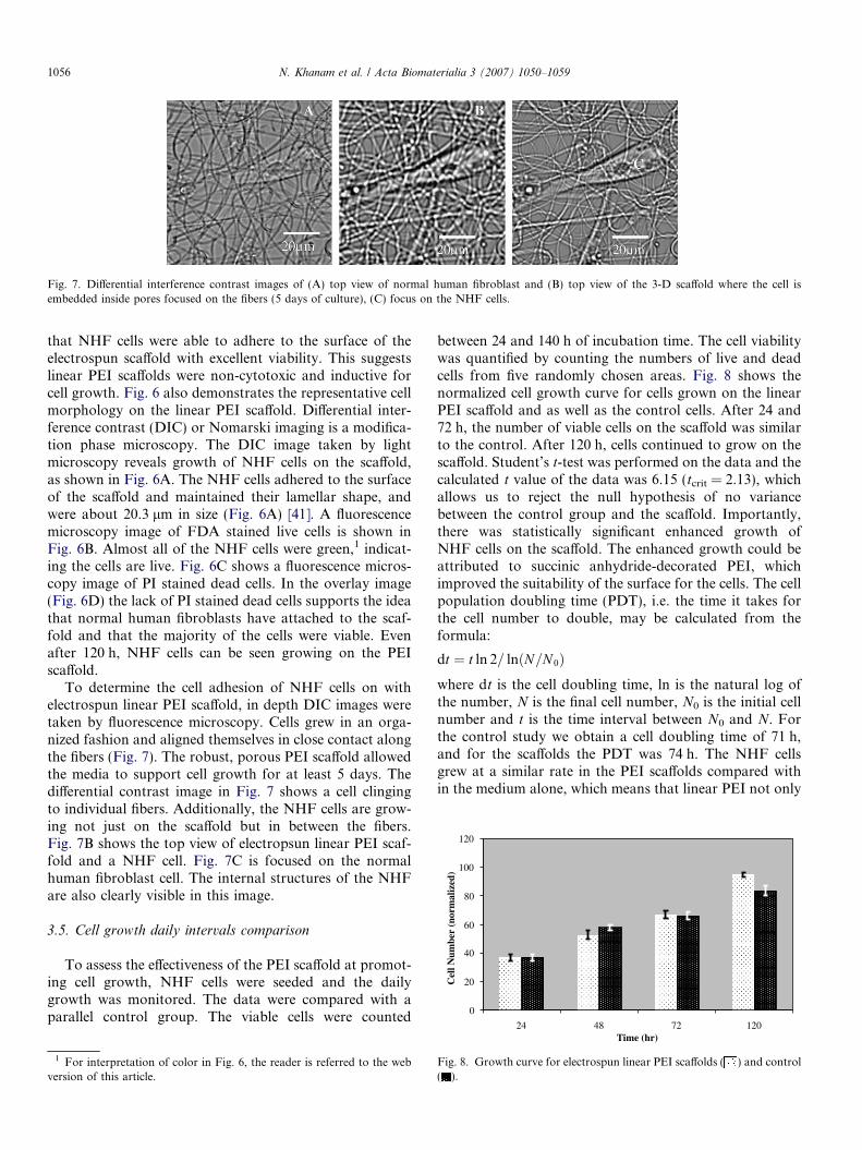
Fig. 7. Differential interference contrast images of (A) top view of normal human fibroblast and (B) top view of the 3-D scaffold where the cell isembedded inside pores focused on the fibers (5 days of culture), (C) focus on the NHF cells.
0
20
40
60
80
100
120
24 48 72 120
Cel
l Num
ber
(nor
mal
ized
)
1056 N. Khanam et al. / Acta Biomaterialia 3 (2007) 1050–1059
that NHF cells were able to adhere to the surface of theelectrospun scaffold with excellent viability. This suggestslinear PEI scaffolds were non-cytotoxic and inductive forcell growth. Fig. 6 also demonstrates the representative cellmorphology on the linear PEI scaffold. Differential inter-ference contrast (DIC) or Nomarski imaging is a modifica-tion phase microscopy. The DIC image taken by lightmicroscopy reveals growth of NHF cells on the scaffold,as shown in Fig. 6A. The NHF cells adhered to the surfaceof the scaffold and maintained their lamellar shape, andwere about 20.3 lm in size (Fig. 6A) [41]. A fluorescencemicroscopy image of FDA stained live cells is shown inFig. 6B. Almost all of the NHF cells were green,1 indicat-ing the cells are live. Fig. 6C shows a fluorescence micros-copy image of PI stained dead cells. In the overlay image(Fig. 6D) the lack of PI stained dead cells supports the ideathat normal human fibroblasts have attached to the scaf-fold and that the majority of the cells were viable. Evenafter 120 h, NHF cells can be seen growing on the PEIscaffold.
To determine the cell adhesion of NHF cells on withelectrospun linear PEI scaffold, in depth DIC images weretaken by fluorescence microscopy. Cells grew in an orga-nized fashion and aligned themselves in close contact alongthe fibers (Fig. 7). The robust, porous PEI scaffold allowedthe media to support cell growth for at least 5 days. Thedifferential contrast image in Fig. 7 shows a cell clingingto individual fibers. Additionally, the NHF cells are grow-ing not just on the scaffold but in between the fibers.Fig. 7B shows the top view of electropsun linear PEI scaf-fold and a NHF cell. Fig. 7C is focused on the normalhuman fibroblast cell. The internal structures of the NHFare also clearly visible in this image.
3.5. Cell growth daily intervals comparison
To assess the effectiveness of the PEI scaffold at promot-ing cell growth, NHF cells were seeded and the dailygrowth was monitored. The data were compared with aparallel control group. The viable cells were counted
1 For interpretation of color in Fig. 6, the reader is referred to the webversion of this article.
between 24 and 140 h of incubation time. The cell viabilitywas quantified by counting the numbers of live and deadcells from five randomly chosen areas. Fig. 8 shows thenormalized cell growth curve for cells grown on the linearPEI scaffold and as well as the control cells. After 24 and72 h, the number of viable cells on the scaffold was similarto the control. After 120 h, cells continued to grow on thescaffold. Student’s t-test was performed on the data and thecalculated t value of the data was 6.15 (tcrit = 2.13), whichallows us to reject the null hypothesis of no variancebetween the control group and the scaffold. Importantly,there was statistically significant enhanced growth ofNHF cells on the scaffold. The enhanced growth could beattributed to succinic anhydride-decorated PEI, whichimproved the suitability of the surface for the cells. The cellpopulation doubling time (PDT), i.e. the time it takes forthe cell number to double, may be calculated from theformula:
dt ¼ t ln 2= lnðN=N 0Þwhere dt is the cell doubling time, ln is the natural log ofthe number, N is the final cell number, N0 is the initial cellnumber and t is the time interval between N0 and N. Forthe control study we obtain a cell doubling time of 71 h,and for the scaffolds the PDT was 74 h. The NHF cellsgrew at a similar rate in the PEI scaffolds compared within the medium alone, which means that linear PEI not only
Time (hr)
ig. 8. Growth curve for electrospun linear PEI scaffolds ( ) and control
F ( ).
N. Khanam et al. / Acta Biomaterialia 3 (2007) 1050–1059 1057
allowed the cells to grow but also showed no toxicity over120 h.
3.6. Fixed cell morphology
The cell morphology on the scaffold was imaged usingscanning electron microscopy. As seen in Fig. 9, the fixednormal human fibroblast cells cultured on the L-PEI/succi-nic anhydride scaffold were attached to the fibers. The cellswere spread throughout the scaffold. This is further evi-denced by their pseudopodia growing along the fibers.From these images we can see these fibers closely mimicnative ECM in their ability to promote cell growth.
3.7. Immunofluorescence with fixed cells on L-PEI/succinic
anhydride scaffold
Normal human fibroblasts were fixed according to theprocedure described in the experimental section. NHF cellswere fixed to localize specific structures within a cell. Theprimary antibody (rabbit anti-Grp78; also known as BiP)was added to the cells attached to the scaffold. BiP is anendoplasmic reticulum heat shock protein. This chaperoneparticipates in protein folding in the endoplasmic reticu-lum. A secondary antibody, Alexa 488 goat anti-rabbit
Fig. 9. SEM images of electrospun linear PEI scaffolds and fixed NHFcells after 5 days of culture (A and B are different areas).
(fluorescent marker), was added to detect the primary anti-body. Nuclei were stained with DAPI. From Fig. 10 themorphology of the normal human fibroblasts cells is clearlyvisible. The cells exhibit their normal phenotypic shape,indicating that the cells are spread apart. These resultsshow that linear PEI scaffold can promote growth for thisparticular cell line. Additionally, the cells are adhering tothe fibers and spread throughout the mesh well after 5 daysof cell culture (Fig. 10A). This evidence indicates that lin-ear PEI promotes cell–scaffold interactions. This studydemonstrates that novel electrospun PEI fibers functionas scaffolds and may be used for soft tissues such a skinreplacement in vivo.
Fig. 10. Fluorescence microscopy images of fixed NHF cells on linear PEIscaffolds, with rabbit anti-GRP 78 conjugated with Alexa 488 goat anti-rabbit (green)/DAPI (blue) stained cells at (A) 10, (B) 40 and (C) 60magnifications.

1058 N. Khanam et al. / Acta Biomaterialia 3 (2007) 1050–1059
4. Conclusion
The use of electrospinning for biomaterials applicationswas reported by Martin and Cockshott in 1977 [45]. Elec-trospinning polymer scaffolds have been investigated onlyrecently. Previous studies found that cells attach to nano-meter diameter fibers [46]. The electrospinning techniqueprovides a unique and efficient approach to fabricating bio-mimetic scaffolds with diameters in the nanometer range.In the present study, linear PEI scaffold supported the3-D growth of NHF cells. We have developed and stan-dardized the scaffold, which promotes the direct formationof new tissue. Results suggest that these scaffolds may beused for animal cell culture in vivo with excellent biocom-patibility. The results obtained from both fluorescence andscanning electron microscopy indicate that cells were grow-ing on the electrospun linear PEI scaffold. This novel struc-ture with a high surface-area-to-volume ratio favors cellattachment by providing a 3-D extracellular environmentsimilar to that found in native tissues. In conclusion, linearPEI scaffolds mimic the native extracellular matrix andthus can serve as a skin substitute. Future studies willinvolve engineering suitable scaffolds with electroactivecomponents for cardiac tissue and artificial neurons.
Acknowledgements
We acknowledge support by the Robert A Welch Foun-dation and SPRING.
References
[1] Schek MR, Wilke NE, Hollister JS, Krebsbach HP. Combined use ofdesigned scaffolds and adenoviral gene therapy for skeletal tissueengineering. Biomaterials 2006;27:1160–6.
[2] Verrier S, Blaker JJ, Maquet V, Hench LL, Boccaccini RA. PDLLA/Bioglass� composites for soft-tissue and hard-tissue engineering: anin vitro cell biology assessment. Biomaterials 2004;25:3013–21.
[3] Rose FRAC, Oreffo ROC. Bone tissue engineering: hope vs. hype.Biochem Biophys Res Commun 2002;292:1–7.
[4] Li JW, Laurencin TC, Caterson JE, Tuan SR, Ko KF. Electrospunnanofibrous structure: a novel scaffold for tissue engineering. JBiomed Mater Res 2002;60:613–21.
[5] Mattews JA, Wnek GE, Simpson DG, Bowlin GL. Electrospinning ofcollagen nanofibers. Biomacromolecules 2002;3:232–8.
[6] Dhiman HK, Ray AR, Panda AK. Characterization and evaluationof chitosan matrix for in vitro growth of MCF-7 breast cancer celllines. Biomaterials 2004;25:5147–54.
[7] Battarai RS, Battarai N, Yi KH, Hwang HP, Cha ID, Kim YH.Electrospun fine-textured scaffolds for heart tissue constructs. Bio-materials 2004;25:2595–602.
[8] Zong X, Bien H, Chung YC, Yin L, Fang D, Hsiao SB, et al.Electrospun fine-textured scaffolds for heart tissue constructs. Bio-materials 2005;26:5330–8.
[9] Ristolainen N, Heikkila P, Harlin A, Seppala J. Poly(vinyl alcohol)and polyamide-66 nanocomposites prepared by electrospinning.Macromol Mater Eng 2006;291:114–22.
[10] Li M, Guo Y, Wei Y, MacDiarmid GA, Lelkes IP. Electrospinningpolyaniline-contained gelatin nanofibers for tissue engineering appli-cations. Biomaterials 2006;27:2705–15.
[11] Buijtenhuijs P, Buttafoco L, Poot AA, van Kuppevelt TH, DijkstraPJ. Tissue engineering of blood vessels: characterization of smooth-
muscle cells for culturing on collagen-and-elastin-based scaffolds.Biotechnol Appl Biochem 2004;39:141–9.
[12] Lu Q, Ganesan K, Simionescu DT, Vyavahare NR. Novel porousaortic elastin and collagen scaffolds for tissue engineering. Biomate-rials 2004;25:5227–37.
[13] Tan KH, Chua CK, Leong KF, Naing MW, Cheah CM. Fabricationand characterization of three-dimensional poly(ether-ether-ketone)/-hydroxyapatite biocomposite scaffolds using laser sintering. Proc InstMech Eng 2005;219:183–94.
[14] Metzke M, O’Connor N, Maiti S, Nelson E, Guan Z. Saccharide–peptide hybrid copolymers as biomaterials. Angew Chem Intl EdEngl 2005;44:6529–33.
[15] Boland ED, Matthews JA, Pawlowski KJ, Simpson DG, Wnek GE,Bowlin GL. Electrospinning collagen and elastin: preliminary vascu-lar tissue engineering. Front Biosci 2004;9:1422–32.
[16] Li M, Mondrinos MJ, Ghandi MR, Ko FK, Weiss AS, Lelkes PI.Electrospun protein fibers as matrices for tissue engineering. Bioma-terials 2005;26:5999–6008.
[17] Reneker HD, Chun I. Nanometer diameter fibers of polymer,produced by electrospinning. Nanotechnology 1996;7:216.
[18] Fog H, Chun I, Reneker HD. Beaded nanofibers formed duringelectrospinning. Polymer 1999;40:4585–92.
[19] Kenawy ER, Layman JM, Watkins JR, Bowlin GL, Mattew JA,Simpson DG, et al. Electrospinning of poly(ethylene-co-vinyl alco-hol) fibers. Biomaterials 2003;24:907–13.
[20] Zeltinger J, Sherwood KJ, Graham AD, Muller R, Griffith GL. Effectof pore size and void fraction on cellular adhesion, proliferation, andmatrix deposition. Tissue Eng 2001;7(October):557–72.
[21] Taylor G. Disintegration of water drops in an electric field. Proc RSoc, A 1964;280:383–97.
[22] Yarin AL, Koombhongse S, Reneker DH. Bending instability inelectrospinning fibers. J Appl Phys 2001;89:3018–26.
[23] Megelski S, Stephens JS, Chase DB, Rabolt JF. Micro- andnanostructured surface morphology on electrospun polymer fibers.Macromolecules 2002;35:8456–67.
[24] Lee KH, Kim HY, La YM, Lee DR, Sung NH. Influence of a mixingsolvent with tetrahydrofuran and N,N-dimethylformamide on elec-trospun poly(vinyl chloride) nonwoven mats. J Polym Sci, Part B:Polym Phys 2002;40:2259–68.
[25] Demir MM, Yilgor I, Yilgor E, Erman B. Electropsinning ofpolyurethane fibers. Polymer 2002;43:3303–9.
[26] Wang X, Drew C, Lee SH, Senecal KJ, Kumar J, Samuelson LA.Electrospun nanofibrous membranes for highly sensitive opticalsensors. NanoLetters 2002;2:1273–5.
[27] Grafe T, Graham K. Polymeric nanofibers and nanofibers webs: anew class of nonwovens. Nonwoven Technol Rev 2003:51–5.
[28] Regnstrom K, Ragnarsson EGE, Fryknas M, Koping-Hoggard M,Artursson P. Gene expression profiles in mouse lung tissue afteradministration of two cationic polymers used for nonviral genedelivery. Pharm Res 2006;23:475–82.
[29] Banerjee P, Weissleder R, Bogdanov A. Linear polyethyleneiminegrafted to a hyperbranched poly(ethylene glycol)-like core: a copoly-mer for gene delivery. Bioconjugate Chem 2006;17:125–31.
[30] Choosakoonkriang S, Lobo BA, Koe GS, Koe JG, Middaugh R.Biophysical characterization of PEI–DNA complexes. J Pharm Sci2003;92:1710–22.
[31] Nimesh S, Goyal A, Pawar V, Jayaraman S, Kumar P, Chandra R,et al. Polyethylenimine nanoparticles as efficient transfectingagents for mammalian cells. J Controlled Release 2006;119:457–68.
[32] Godbey WT, Wu KK, Mikos AG. Poly(ethylenimine)-mediated genedelivery affects endothelial cell function and viability. Biomaterials2001;22:471–80.
[33] Helander IM, Alakomi HL, Latva-Kala K, Koski P. Polyethylene-imine is an effective permeabilizer of Gram-negative bacteria.Microbiology 1997;143:3193–9.
[34] Helander IM, Latva-Kala K, Lounatmaa K. Permeabilizing action ofpolyethyleneimine on Salmonella typhimurium involves disruption of

N. Khanam et al. / Acta Biomaterialia 3 (2007) 1050–1059 1059
the outer membrane and interactions with lipopolysaccharide.Microbiology 1998;144:385–90.
[35] Boussif O, Lezoualc’h F, Zanta MA, Mergny MD, Scherman D,Demeneix B, et al. A versatile vector for gene and oligonucleotidetransfer into cells in culture and in vivo – polyethyleneimine. Proc NatAcad Sci USA 1995;92:7297–300.
[36] Forrest ML, Meister GE, Koerber JT, Pack DW. Partial acetylationof polyethylenimine enhances in vitro gene delivery. Pharm Res2004;21:365–71.
[37] Hu Y, Carr PW. Synthesis and characterization of new zirconia-basedpolymeric cation-exchange stationary phases for high-performanceliquid chromatography of proteins. Anal Chem 1998;70:1934–42.
[38] Tanaka R, Ueoka I, Takaki Y, Kataoka SS. High molecular weightlinear polyethyleneimine and poly N-methylethyleneimine. Macro-molecules 1983;16:849–53.
[39] Ngo TT. Colorimetric determination of reactive amino groups of asolid support using Traut’s and Ellman’s reagents. Appl BiochemBiotechnol 1986;13:213–9.
[40] Ngo TT. Coupling capacity of solid-phase carboxyl groups. ApplBiochem Biotechnol 1986;13:207–12.
[41] Domnina LV, Ivanova OY, Margolis LB, Olshevskaja LV, RovenskyYA, Vasiliev JM, et al. Defective formation of the lamellar cytoplasmby neoplastic fibroblasts. Proc Nat Acad Sci USA 1972;69:248–52.
[42] McCallagh C, Saunders GC. Enhanced adsorption of Cd(II) on ahydrous Al(III) floc in the presence of a modified form of polyethy-lenimine. Water Res 2005;39:2799–806.
[43] Peterson H, Fechner PM, Fischer D, Kissel T. Star-shaped poly(eth-ylene glycol)-block-polyethylenimine copolymers enhance DNA con-densation of low molecular weight polyethylenimines.Macromolecules 2002;35:6867–74.
[44] Breeuwer P, Drocourt JL, Bunschoten N, Zwietering MH, RomboutsFM, Abee T. Characterization of uptake and hydrolysis of fluoresceindiacetate and carboxyfluorescein diacetate by intracellular esterases inSaccharomyces cerevisiae, which result in accumulation of fluorescentproduct. Appl Environ Microbiol 1995;61:1614–9.
[45] Martin CE, Cockshott ID. US Patent 4,043,331, 1977.[46] Xu YC, Inai R, Kotaki M, Ramakrishna S. Aligned biodegradable
nanofibrous structure – a potential scaffold for blood vesselengineering. Biomaterials 2004;25:877–86.


![Microwave-assisted synthesis of 3-aminobenzo[b]thiophene ...sro.sussex.ac.uk/id/eprint/52619/4/c5ob00819k.pdf · Microwave-assisted synthesis of 3-aminobenzo[b]-thiophene scaffolds](https://static.fdocuments.net/doc/165x107/5f0d921a7e708231d43b0398/microwave-assisted-synthesis-of-3-aminobenzobthiophene-sro-microwave-assisted.jpg)


