ELECTRONIQ -7 CIRCUITS - Navy Radio · n~ klkl n mmn 1 kun n m tt lc3 nm installation and...
20
n~ n mmn n m TT n m kLkL 1 KUN lC3 INSTALLATION AND MAINTENANCE BOOK -7 ELECTRONIQ CIRCUITS &- DEPARTMENT OF THE NAVY NAVAL SHIP ENGINEERING CENTER PUBLISHED: APRIL 1965 CHANGE 2 : SEPTEMBER 1968 (0967-000-0122)
Transcript of ELECTRONIQ -7 CIRCUITS - Navy Radio · n~ klkl n mmn 1 kun n m tt lc3 nm installation and...

n~ n m m n n m T T n m
kLkL 1 K U N lC3
INSTALLATION AND
MAINTENANCE BOOK
-7 ELECTRONIQ CIRCUITS &-
D E P A R T M E N T OF T H E N A V Y N A V A L S H I P E N G I N E E R I N G C E N T E R
PUBLISHED: APRIL 1965 CHANGE 2 : SEPTEMBER 1968 (0967-000-0122)

BOX SCORE ELECTRONIC CIRCUITS HANDBOOK
NAVSHIPS 0967.W0.0120
CHANGE 2
EDITION
Basic Change 1 Change 2
PUBLICATION DATE
April 1965 December 1966 September 1968
STOCK NUMBER
0967-000-0120 0967-000-012 1 0967-000-0122
ELECTRONIC CIRCUITS
T i t l e Page ii t h r u x v i A and B
Change 2 Change 2 Change 2
NAYSHIPS 0967~000.0120
LIST O F E F F E C T I V E P A G E S
EFFECTIVE PAGES
SrcLion 9 9-A-1 t h r u 9-A-9 O r i g i n a l 9-A-10 t h r u 9-A-21 Change 1 9-B-1 and 9-8-2 O r i g i n a l 9-B-3 t h r u 9-8-7 Change 1
S e c t i o n 10 10-A-1 and 10-A-2 O r i e i n a l
2-1 t h r u 2-13 O r i g i n a l 16-A-3 c i c u i"-~-ii 1 ln-8-1 r h n i 10-8-4 O r i g i n a l
S e c t i o n 3 10-B-5 t h r u 10-8-7 Change 1 3-1 t b r u 3-37 U r i g i n a l
S e i i i u i i 11 S e c t i o n 4 ,, " 7
LA-'.L and :I-.-? 2r ig i i r .n l 4-8-1 t h r u 4-A-43 O r i g i n a l 11-A-3 and 11-A-4 Or ig ina l IChange 1 4-6-1 t l r ru 4-B-35 O r i g i n a l 11-A-5 and 11-A-6 Change l lChange 2 4-C-1 t h r u 4-C-22 O r i g i n a l 11-A-7 t h r u 11-A-37 Change 2 4-0-1 t h r u 4-9-19 O r i g i n a l 11-B-1 and 11-8-2 O r i g i n a l l c h a n g e 2
11-B-3 t h r u 11-B-12 Change 2 S e c t i o n 5
5-A-1 t h r u 5-A-8 O r i g i n a l 5-A-9 t h r u 5-A-34 change I 5-B-1 t h r u 5-B-4 O r i g i n a l 5-C-1 t h r u 5-C-4 O r i g i n a l
S e c t i o n 6 6-A-1 t h r u 6-A-5 O r i g i n a l 6-A-6 t h r u 6-A-6CC Change 1 6-A-7 t h r u 6-A-21 O r i g i n a l 6-A-22 t h r u 6-A-22EFF Change 1 6-A-23 and 6-A-24 O r i g i n a l b-A-25 and 6-A-26 Cr ig ina l iZhange 2 6-A-27 t h r u 6-A-38 O r i g i n a l 6-A-39 t h r u 6-A-43 Change 1 6-B-1 t h r u 6-8-8 O r i g i n a l 6-8-9 and 6-8-10 Change I lChange 2 6-a-11 t h r u 6-B-18 Change 1 6-8-19 and 6-8-20 Change l1Change 2 6-B-21 t l i r u 6-B-44 Change 1 6-B-45 and 6-8-46 Change ZIChange 1 6-B-47 t h r u 6-B-57 Change 1
S e c t i o n 7 i-:,.> i d 7-?~-? Or i$ ina l /Chanee 2 7-8-3 t n r u 7-8-7b O r i g i n a l
C C C f ' " " .- " 8-h-l chr; 8-A-5 O r i g i n a l 8- ' 6 ...
‘L- La2rt, S-;.-27 Change I 8-B-1 and 8-b-2 3rigin-1 8-R-3 a n d 8-8-4 O r i g i n a l l c h a n g e 1 8-B-5 and 8-8-6 Change IIChange 2 8-8-7 t h r u 8-B-23 Change 1
...... ~~ -. ,, " . z ~ d 13-A-2 n-:-;--, - . A a 13-A-? and I?-&-4 Gr ig inaI lChange 2 13-A-5 t h ru 13-A-15 Chanze 2 - 13-8-1 t h r u 13-B-4 U r i g i n a l 13-B-5 t h r u 13-B-9 Change 2
S e c t i o n 14 A - t t . ru I/-A-38 O r i z i n u l - 14-A-39 and 14-A-40 Or ig ina l ICi rangr 2 11-2-41 t h r u 14-A-46 Change 2 14-A-46A and Blank Change 2 14-A-47 t h r u 14-A-70 Change 2 14-8-1 t h r u 14-5-4 v r i g i n a l 14-B-5 t h r u 14-8-16 Change 2
S e c t i o n 15 i j -~~- i ch ru 15-A-22 . .
O ~ i ~ i l l ~ l . - * - ? 7 -. ::.;-.>: A - ~. -a . . -. ~/::<:IIL~ 2 - ; j -~-; an; ;;-:.; Z r i g i n a l
15-8-3 t h r u 15-B-11 Change 2
S e c t i o n 16 i b - A - 1 t n r u lo-A-+ d r i a i n a i 16-A-5 and 16-A-6 Or ig ina l lLhange i . , 1 tl-A-7 ~ i l x u 16-A-13 ", ... "
' ."b,rLC L
16-5-1 and 16-8-2 C r i g i s a i 16-8-3 t h r u 16-B-9 i oange 2
ELECTRONIC CIRCUITS
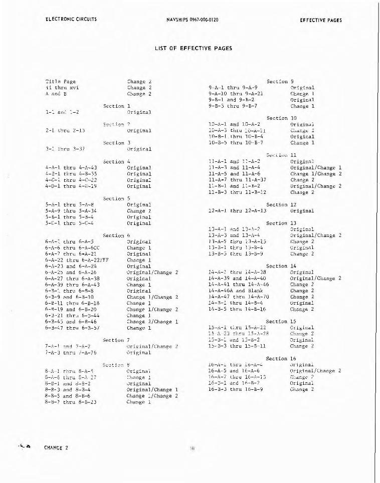
Section 17 17-1 and 17-2 Original 17-3 thru 17-11 Change 2
Section 18 18-A-1 and 18-A-2 OriginalIChange 2 18-A-3 thru 18-A-5 Change 2 18-8-1 and 18-8-2 Original 18-B-3 thru 18-B-6 Change 2
Section 19 19-A-1 and Blank Original 19-8-3 thru 19-B-12 Change 1 19-8-13 and 19-8-14 Change 21Change 1 19-8-15 thru 19-8-32 Change 1 19-C-1 and 19-C-2 Original 19-C-3 thru 19-C-11 Change 1
Section 20 20-A-1 thru 20-A-5 Original 20-A-6 thru 20-A-8 Change 1 20-A-9 and 20-A-10 Change 11Change 2 20-A-11 and Blank Change 2 20-8-1 and Blank Original 20-C-1 thru 20-C-7 Original
Section 21 21-A-1 thru 21-A-6 Original 21-A-7 and 21-A-8 OrieinalIChanre 2 - 21-A-9 thru ZI-A-~I change 2 21-8-1 and 21-B-2 Original 21-8-3 and 21-8-4 Originallchange 2 21-B-5 thru 21-B-7 Change 2
Section 22 22-1 thru 22-6 Original 22-7 thru 22-39 Change 2
Section 23 23-1 thru 23-4 Original 23-5 thru 23-17 Change 2
CHANGE 2

ELECTRONIC C I R C U I T S
Section
N A V S H I P S 0967-000-0120
TABLE OF CONTENTS
I Introduition
Purpose Use Scope
2 General Inlormotion on Electron Tube C l r r v l t s
Definitions of Letter Synbols I:sed :.nnscrilc:;nn or >).;;no; s List of Symbols
Biasing Xethods Cathode Bias Crid.Lca!< Bias
Fixed Bias Classes of Amplifier Operation
Class A Operation Class B Operation Class AB Operation Class C Operation
Coupling ilethods R-C Coupling Impedance Coupling Transformer Coupling
Direct Coupling Time Constants
R-C Circuits R-L Circuits
3 Gcncro! Inloimmtion an S e m i ~ o n d ~ ~ t a r C ; r c u ; t i Definitions of Letter Symbols Used
Construction of Symbols Alphabetical List of Semiconductor Letter Symbols
Diode Circuits Junction Diode Theory Forward-Biased Diode Stabilization Reverse-Biased Diode Stabilization Doublr-Diode S ~ a L i l i ~ a ~ i o n Diode Voltage Stabilization
-. ~rmperaturr Compensation
Shtinr-1.imiting Diode Diode AGC Circuit WPI' Switching (Fnllr-~"y13r n i c d e ) Photodiodes Tunnel Diodes
T r i o d e iommon-Base CircuiLs - . nias (Common Sasri
Triode Common-Emitter Circuits " ~ . 2L.:> ~- * J ~ ~Lics (C owJlld,, r l l , i L L L I ) B z .. rss Stabi1izetion
Triode Cornon-Collecrnr C i r i - l i i r s
Bias (Common Collector) Tetrade, Power, and Special-Purpose Circuits
Tetrodes ,..""+<-" '""*?..A,. ,n"..k,m-e""..A T..".."<"*"-\ .--- "-- \ - - - "-- --"-- .-",."A"L"., Spacistor Tetroide
T A B L E O F C O N T E N T S

ELECTRONIC CIRCUITS
Sec,ion
Crystal-Xixer Tetrade Point-Contact Tetrode
Power Transistors and Considerations Special-Purpose Transistors and Circuits
PNPK Triode (Hook Collector) Unipolar (Field-Effect) Transistor Unijunction Transistor (Double-Based Diode) Surface-Barrier Transistor PNIP-KPIN Transistor Drift Transistor Diffused-Base (XESA) Transistor Silicon Controlled Rectifier Phototransistor Thermistor
Classes of Amplifier Operation Class A Class B Class A8 Class C
Coupling \lethods R-C Coupling Impedance Coupling Transformer Coupling Direct Coupling
Time Constants Hybrid Parameters
4 Po.., Supply Cirruitr P o r t A. Electron-Tube Circuits
Single-Phase, Half-Wave Rectifier Single-Phase, Full-Wave Rectifier Single-Phase, Full-Wave Bridge Rectifier Three-Phase, Half-Wave (Three-Phase Star) Rectifier Three-Phase, Full-Wave (Single "Y" Secondary) Rectifier Three-Phase, Full-Wave (Delta Secondary) Rectifier Three-Phase, Half-Wave (Double "Y" Secondary) Rectifier Half-Wave Voltage Doubler Full-Wave Voltage Doubler Voltage Tripler Voltage Quadrupler High-Voltage (CRT) Supply, Audio Oscillator Type High-Voltage (CRT) Supply, R-F Oscillator Type
Part B. Semiconductor Circuits Semiconductor Rectifiers Single-Phase, Half-Wave Rectifier Single-Phase, Full-Wave Rectifier Single-Phase, Full-Wave Bridge Rectifier Three-Phase, Half-Wave (Three-Phase Star) Rectifier Three-Phase, Full-Wave (Single "Y" Secondary) Rectifier Three-Phase, Full-Wave (Delta Secondary) Rectifier Three-Phase, Half-Wave (Double "Y" Secondary) Rectifier Half-Wave Voltage Doubler Full-Wave Voltage Doubler Voltage Tripler Voltage Quadrupler High-Voltage (CRT) Supply, Square-Wave Oscillator Type DC-to-DC Converter Dosimeter Charper (DC-to-DC Converter)
TABLE OF CONTENTS

ELECTRONIC CIRCUITS NAVSHIPS 0967-000-0120 TABLE OF CONTENTS
section
Port C. Electromech~nicoi Circuits Rutsti<,g Z:eitiur,cihzfiiial Systems Uynamotor Inverter Vibrator-Type Power Supplies
Nonsynchronous Vibrator Supply Synchronous Vibrator Supply
Port D. Filter Circuits Power-Supply Filters
Shunt-Capacitor Filter 3-i Capacitor-inpur iiirri I-C Capacitor-Input Filter L-C Choke-Input Filter Resonant Filter
5 v ~ i t o ~ e - ~ e ~ ~ i o t o r C ~ r c u ~ t r
Port A . Electron-Tube Circuits Gas-Tube Regulator Electronic Regulator
D-C Regulator using Pentode Amplifier D-C Regulator using Cascode Twin-Triode Amplifier D-C Regulator using Cascade Twin-Triode Amplifier D-C Regulator using Twin-Triode and Pentode (Balanced Input) D-C Regulator using Pentode and Twin-Triode (Balanced Output)
Electromagnetic Regulators Part B . Semiconductor Circuits
Semiconductor Regulators BrrdbCuw?: Dlu& S ~ L U L ~ ~ - T ~ ~ ~ - Xi-gulai~r
Part C. Elertromechanicol Circultr Electromechanical Regulators
6 Amplilier Circuits P ~ r t A. Electron-Tube Circuits
Audio Amplifiers R-C Coupled Triode Audio Voltage Amplifier R-C Coupled Pentode Audio Voltage Amplifier Impedance-Coupled Triode Audio Voltage Amplifier Transformer-Coupled Triode Audio Voltage Amplifier Single-Ended, R-C Coupled Triode Audio Power Amplifier Single-Ended, R-C Coupled Pentode Audio Power Amplifier Push-Pull (Class A, AB, and B) Audio Power Amplifier
Phase Inverters Iransformer Type Inverter
Single-Tube Paraphase Inverter lwo-lube Parapnase Inverter TJraphas*, " .L..a. 7 - > ".a..i"ui-Luupis- ;.i.s;>=i
Differential Paraphase Inverter Cathode Follower
iow-Level Video Cathode Foiluwar Pulse Cathode Follower
\ririeo Amplifiers Triode Video Amplifier .Ycntode Video .47piifler . r . :.; d e Driver video Amplifier Beam-Power Video Driven Amplifier Chain (Mixer, Amplifier, and Driver) Video Amplifier Cathode-Coupled (In-Phase) Video Amplikier
Squelch Circuits AiC-Controlled Audio &~pli:ier
CHANGE 2

TABLE OF CONTENTS ELECTRONIC CIRCUITS
Section
R-F Amplifiers Pentode R-F Voltage Amplifier Triode Grounded-Grid R-F Amplifier Cascade R-F-Amplifier Cascode R-F-Amplifier Travelling-Wave Tube Amplifier Tuned Interstage (I-F) Amplifier Triode R-F Buffer Amplifier Pentode R-F Buffer Amplifier Frequency Multiplier (R-F) Push-Push Frequency Multiplier (R-F) Single-Ended (Class B or C) R-F Amplifier Push-Pull (Class B or C) R-F Amplifier Multicavity Klystron R-F Amplifier
Direct-Coupled (D-C) Amplifier Push-Pull Direct-Coupled (D-C) Amplifier
Deflection Amplifiers Voltage Deflection Amplifier (far Electrostatic CRT) Current Deflection Amplifier (for Electromagnetic CRT)
Feedback Amplifiers Positive Feedback (Direct, Regenerative) Amplifier Negative Feedback (Inverse, Degenerative) Amplifier
Part 8. Semicand~rtor Circuits Audio Amplifiers
Direct-Coupled Audio Amplifier Transistor Chopper (D-C) Amplifier R-C Coupled Audio Amplifier Impedance-Coupled Audio Amplifier Transformer-Coupled Audio Amplifier
Audio Power (Class A, AB, and B) Amplifier, Push-Pull, Transformer- Coupled Audio Power Amplifier, Push-Pull, Single-Ended Complementary Circuit Audio Power Amplifier, Push-Pull, Single-Ended Series-Connected Circuit ~ ~ d i ~ Power Amplifier, Push-Pull, Capacitance-Diode Coupling Audio Power Amplifier, Compaund-Connected Audio Power Amplifier, Bridge-Connected Phase Inverters
One-Stage Phase Inverter Two-Stage Phase Inverter
Video Amplifiers Wide-Band Video Amolifier.
R-F Amplifiers Tuned Interstage (I-F) Amplifier Tuned Common-Base R-F Amplifier Tuned Common-Emitter R-f Amplifier
7 Olcillotor Circuitr Port A. Electron-Tube Circuits
L-C o~~i111t0r~ Tickler-Coil Oscillator Hartley Oscillator Colnitts Oscillator Clapp Oscillator Tuned-Plate Tuned-Grid Oscillator Electron-Coupled Oscillator Ultraudion ~scillator R-C Oscillators
R-C Phase-Shift Oscillator Wien-Bridge Oscillator
CHANGE 2

ELECTRONIC CIRCUITS
Sec?i.n
Electromechanical Oscillators Crid-Cathode (Hiller) Crystal Oscillaror Grid-Plate (Pierce) Crystal Oscillator Electran-Coupled Crystal Oscillator Overtone Cathode-Coupled (Butler) Crystal Oscillator Magnetostriction Oscillators
Negative-Resistance Oscillators Dynatran Oscillator
'~ransitron (Negative GH) Oscillator Kallltron l.t'ush-k'111 I ) <ls,-i I !>:or
Tuned-Line Oscillators Lighthouse-Tube Oscillator Lecher-Wire Oscillator
,, ---- *--- n--: , , -*-- 1 " s,llL. "<, 1,,71 ,, Reflex Klvstran Oscillator
Port B. Semiconductor Cirruitr L-C oscillator^
Tickler-Coil (Armstrong) Oscillator Hartley Oscillator colpitis Oscillator Clam Oscillator ~=~
R-C Oscillators R-C Phase-Shift Oscillator Wien-Bridge Oscillator
Electromechanical Oscillators Tickler-Coil Feedback Crystal Oscillator Colpitt~ Crystal Oscillator Overtone Crystal Oscillator
e ~~ ! : i . , i t ,~s .~ ciri*iti
Pan A . Electron-Tube Cirruitr Astable (Free-running) Multivibrators
Triode Plate-to-Grid Coupled Astable Multivibrator Pentode Electron-Coupled Astable Multivibrator Triode Cathode-Coupled Astable Multivibrator
Bistable (Start-Stop) Multivibrators Triode Eccles-Jordan (Flip-Flop) Multivibrator Pentvdr Eceles-Zordan (Flip-Flop) Nultivibrator
Xonastable (One-Shot) Multivibrators Triode Plate-io-Grid Coupled Xanostabie kiiiriuibraror Triode Common-Cathode-ResisTor Fonostable M~;ltiribrntor
Phantastron Multivibrator Pefl B Semiconductor C;rcui+r
Astable Multivibrators nasic Free-Running Asrable Xuirivihrator
Bistabie Kuitivibrators %sic Flip-fiop > l u i r i v i b i a i u r Direct-Coupled (or Binary) 3~ltivibrator 1 , , , 1 1 1 . , l - l ~ ~ l . . L " 1 - , , , , . , , , . . , . . . . _.j" l._..a "."_". i _ i _ _ i i
Saturating Multlvlbrator Nonsatilratin~ Milltivihratnr Relay Control Multivibrator
Monostable Multivibrators Basic One-Shot Nultivibrator
9 n,- .c:-- ".A <L..L =-.:."A n..:l,".-.c: .... :.. . , , 3 -" " ". Pa0 A . Electron-Tube C ~ r c u ~ t ~
Free-Running PRF Generator
TABLE OF CONTENTS

ELECTRONIC CIRCUITS NAYSHIPS 0967-OW.0120 TABLE OF CONTENTS
Triggered Blocking Oscillators Parallel-Triggered Blocking Oscillator Series-Triggered Blocking Oscillator Fast-Recovery Blocking Oscillator Pulse-Frequency Divider Distance-Mark Divider
Shock-Excited Ringing Oscillator Shock-Excited Peaking Oscillator
Part B . Scmiconductorcirruitr Free-Running PRF Generator Triggered Blocking Oscillators
Basic Blocking Oscillator Nonstaurating, Diode-Clamped Blocking Oscillator
10 SweepGenerotor Circuits Port A. Electron-Tube Circuits
Sawtooth-Wave, Gas-Tube Sweep-Generator Circuits Neon Gas-Tube Sweep Generator Thyratron Sweep Generator
Triode Sawtooth-Wave Sweep Generator Circuits Basic Triode Sawtooth Sweep Generator Bootstrap Sweep Generator
Triode Trapezoidal-Wave Sweep Generator Port B . Semirondu~tor Circuits
Sawtooth-Wave Circuits Unijunction (Double-Base Diode) Four-Layer Diode
11 Detector (Dcmodul.tion) Circuits
P ~ l n A . Electron-Tube Circuits AM Detectors
Diode Detectors Diode Detector with AVC Diode Detector (with Noise Limiter)
Grid-Leak Detector Plate Detector Infinite-Impedance Detector Regenerative Detector Superregenerative Detector Product Detector Coherent (Synchronous) Detector
FM (or PM) Detectors Foster-Seeley Discriminator Travis Discriminator Ratio Detector Gated-Beam Detector
Video Detectors Basic Video Detector
Part 8 . Semiconductor Circuits
AM Detectors Voltage Output Diode Detector Current Output Diode Detector Coormon-Emitter Detector Common-Base Detector
EM Detectors Faster-Seeley Discriminator Ratio Detector
Video Detectors Basic Video Detector
**To be issued in later changes
CHANGE 2

E L E C T R O N I C C I R C U I T S T A B L E O F C O N T E N T S
!? ,,. p:.. .:.. m,*., .,.. "... Par, A . Eic<r,on-Tube i i r c u i i r
Audio Mixers Common Plate-Load Audio Mixer Separate Plate-Load Audio Mixer
Video Miners Common-Cathode Video Mixer Common-Plate Video Mixer
Port 8 . Semicondu<tor Ci rcui ts , - I J Frequency (Heterodyne) Convener Ci rcul t r
Par, A . E ler t ron-Tube C i r r v i t s
Mixers Diode Mixer TriuJr >iin%r Pcntode Xixer Pentagrid Mixer Balanced Mixer Pentagrid Converter
Port B. Semiconductor Ci rcui ts
?lixers Diode >fixer Triode Mixer Microwave Diode Mixer
Autodyne Converter 14 ~ o d u l o t o r Ci rcui t3
O . ~ . . c , ...... ?..L.-: :.. , " , , ". ..*.,,",.-,""=.,,.".,. Amplitude ?lodulation (ALE)
Choke (Heising) Modulator Transformer-Coupled Plate Modulator Transformer-Coupled Control-Grid Modulator Transfarmer-Coupled Suppressor-Grid Modulator Transformer-Coupled Screen-Grid Modulator Transformer-Coupled Plate and Screen Modulator Transformer-Coupled Cathode Modulator Series Modulator Double-Sideband Modulator
Single-Sideband Modulators (SSB) Balanced (Push-Pull Carrier Input) Modulator Balanced (Parallel Carrier Input) Modulator aaianced Bridge Xoduiator Product Modulator
Phase Moduiacars (PYj " - - > - r,. - --- LJ-z..; ----
..""uA-L"L
i'lrasitron ?iodulator Frequency Modulators (9!)
B... s a ~ s & - A actanii-TuSe >fodulator
Balanced Reactance-Tube Modulator Ptilse Modulators
Spark-Gap Modulator .... ~ s ~ ~ r a ~ r o n (Gas-Tubrj M u d u i a i u r kard-Tube >lodulator
Par, 8. Semiconductor Ci rcui ts
Amplitude Modulation (ALL) nase-inject~on Moauiator Emitter-Injection Modulator Collector-Injection \loduintor
c j n $ l e S i d e h a n d X n d i i l i t o r !SS9)
rxio be Lssued ln i arer cnanges

ELECTRONIC CIRCUITS
Section
Basic Balanced Modulator Balanced Complementary Smarty
Frequency Modulators (FM) Basic Reactance Modulator
15 Limiter (Clipper) Cirrvi tr
Port A . Elc<tron-Tube Circuits Diode Limiter
Series, Positive-Lobe Diode Limiter Series, Negative-Lobe Diode Limiter Parallel, Positive-Lobe Diode Limiter Parallel, Negative-Lobe Diode Limiter Two-Diode, Positive and Negative Lobe Diode Limiter
Triode Limiters Triode Grid Limiter Triode Saturation Limiter Triode Ciltoff Limiter Triode Overdriven Amplifier Limiter
Pentode Limiters Video Pentode Limiter R-F Pentode Limiter
Port 8. Semiconductor Circuits Diode Limiters
Series Limiter, Positive-Lobe Series Limiter, Negative-Lobe Parallel Limiter, Positive-Lobe Parallel Limiter, Negative-Lobe Two-Diode, Positive and Negative Lobe Limiter
Triode, Basic Cornon-Base Limiter 16 Clamper iD.C Restorer) Cir<uits
Port A. Electron-Tube Circuits Diode Clampers
Negative Diode Clamper Positive Diode Clamner Negative-Biased Diode Clamper Positive-Biased Diode Clamper
Triode Clampers Basic Single-Tube Clamper Synchronized Clamper
P o n B. Scmiconducto, Circuits Diode Clam~ers
Negative-Diode Clamper Positive-Diode Clamper Negative-Biased Diode Clamper Positive-Biased Diode Clamper
Triode Basic Common-Base Clamper 17 Worelhaping Circuitr
R-C Differentiator R-L Differentiator R-C Integrator R-L Integrator Saturable-Core Reactor Peaking Circuit Semiconductor Pulse Shaper
18 Councr Circuits
Part A. E l c r t r o ~ T u b c Circuits Positive Diode Counter Negative Diode Counter Step-by-step (Step) Counter
TABLE OF CONTENTS
Pop.
CHANGE 2

ELECTRONIC CIRCUITS
s.ct;on
Part 6 . S c m ~ o n d u c r o r i i rcu i i ,
Positive Diode Counter Negative Diode Counter - Step-by-step (Step) Counter
19 Logic Circuit. Port A. ElertronTube Circuits
Rn 8. Semiconductor Circuits
Logic Polarity n ~ " : + : . . ~ T""<* & A - - . - - - a. -
Negative Logic Diode Logic
OR Gate AND Gate Rectangular Matrlces Encoding Matrices Decoding Eiatrices Two-Level AND-OR Gate Half-Adder Circuits Full-Adder
: Transistor Logic
\ Transistor "OR" Gate Transistor "AND" Gate Transistor "NOT" Circuit Transistor NOR Gate Transistor NAND Gate Transistor clip-Flop iircuiia
i Emitter-Follower Circuits Lamp Drivers and Relay Pullers
b- - Port C . Merhonico! Circu8tl
Switch Logic OR Circuits AND Circuits Flip-Flop Circuits Two-Way and Three-way Circuits
2 0 Timc-Delay Circuifs Port A. Electron-Tube Circuits
Phantastron Circuits Basic Phantastron Circuits Fast-Recovery Phantastron Circuit Electromechanical (Acoustic) Delay iines
Part 8. Semiconductor Circuits
Part C . An8lical Delay Liner ~.. ~~ccrromagnetic "lay Lines
2! Corr:~ ! C i ? ~ " i , * Pa,, A Eiec,ron-Tube C l r ru l t r
AGC CAVC) Circuits Cimple AGC Circuit
ATCCiri~its Phantastron AFC Circuit Tlryatron AEC Ciri~it Reactance Tube AFC Circuit D-C Amplifier AFC Circuit
Servomechanism Circuits Synchro Control System Servo Motor-Controller Circuit Resolver-Driver Circuir -. "~ ... &>... L , . . l , n"-""-".. ,-; *,.,, ;, z!!a,r-,>r ,"= LA " -.--- "- -------
**TO be issued in later changes
CHANGE 2 ...
X I , ,
TABLE OF CONTENTS

ELECTRONIC CIRCUITS
Section
Part 0. Semiconduoor Cir.ui,r AGC (AVC) Circuits
Transistor "NOT" Gate Emitter-Current Control Auxiliary-Diode (Shunt) Auxiliary-Diode (Collector-Controlled)
22 Cathode-Ray-Tube Circuit3
Electrostatic Basic Oscilloscope Circuits Synchroscope Circuits CRT Display Circuits
A-Scope Presentation J-Scope Presentation B-Scope Presentation C-Scope Presentation
Electromagnetic PPI Scan Other Types of Scans
Blanking DC Restoration Damper and Flyback
23 Filter Circuits
High-Pass Low-Pass Band-Pass Band-Rej ection
TABLE OF CONTENTS
CHANGE 2

ELECTRONIC CIRCUITS NAVSHIPS 0967.000-0120 PREFACE
POLICY AND PURPOSE T h e equipment handbooks are devoted ro
.. . information o n a part icular equipmenr c l a s s ; I ne t i e c r r o n i c s lnstai lat lon and hln in ten~ they provide general rcsr procedures. adjusr-
ance Rook (EILIB) h a s been es rabl i shed as the menrs, general servicing iniormation, and f ield medium for c ~ l l e c r i n ~ . publishing. and dirr i ibur- change idenriiicarion da t a . ing, in one convenient documentation source, t hose subordinate mainrenance and repair poli- c i e s , insrallarion pracr ices , and overall e l r c - rronics equipment and marerial-handling procr- d w e s required to implement t he major pol ic ies cp, fnrrh ~~~ :" r - ~ . ~ ~ ~ - . OC-A ..i .i- xl-..-l rt.:-- , .-. , " , - ". v...ru l e cnn i ca l \lanual. All dara contained a,ithin the E l 5 5 3re ~ u t h o r i r a r i ~ ~ e , and dc i i s c i he i i author- ity irom Chapter 96-0 oi rhe Nava l Ships Tech- n ica l Llanual, a s es rab l i shed in accordance a,irh i r r i c i c i?iii, i 5. havy heRularions
Since i t s inception, however, rhe EIMB h a s been expanded ro include se lec ted informarion of general interest t o electronic insral lat ion and maintenance personnel . T h e s e i tems are such as would generally b e contained in rexr- books, periodicals , or technical pape r s , and form (along with t he information c i t ed above) a comprehensive, s ingle-source ie ference docu- ment. In applicarion t he FI\IR is rn h e i l q e ( i
for iniormarion and guidance by a!! mi!itary and civil ian personnel involved in the ins ta l la t ion , mainrenance, and repair u i e lec t ronic rquipmcnr under cognizance, or rrchnicul control , o f t he Naval Ship Sys tems Command (NAVSHIPS). All information, insrructions, and procedures in r he EIMB supplement such instructions and da ta supplied in equipment technical manuals and other approved maintenance publ ica t ions .
ORGANIZATION - i hc EM6 i s organized inro a s e r i e s oi
L. ~ ~ ~ o d b ~ . ? k ~ c 0 .fiord maximum ficnib;iiti ~ - 2
c;ise in handling. The handbooks uir s tocked and i ssued a s separa te i tems so chat acrivir ies requiring extra copies of any handbook may obtain them wirh relarive ease.
The handbooks fal l a i t h i a rwo ca tegor ies ;encral in fomat ion h a n d b u a k ~ n r d cyuipmrnr- oriented handbooks. The gcnrra l informarion handbooks contain dara which are o i inreresr ro all personnel involved in insral larion and I ~ ~ ; ~ L ~ ~ ~ ~ ~ ~ ~ ~ , regardless oi iheir equipment spec ia l ty . T h e r i r les o f t he various genera l information handbooks g i w only an overall idea of rheir dara conienr: a more compierc dezr r ip t ion o! each hzndbaak is p;ovidid in :hi - ,.. ,, . UL..L.*. ,,'3,A""""%.
The following tab le l i s r s a l l handbooks of r h e s e r i e s . together with rheir old and new NAVSHIPS numbers. ( T h e old XAVSHIPS number s~a re shown in parentheses . ) T h e new ! 4~ \~ "sF ! !US "--!.<!$, z!:k2;5 ze: ;:czcz:!:;
lmprinred on a l l handbooks of the EIhlB s e r i e s , serve a l s o as the s tock numbers which are ro be used on any requisi t ions submitred
HAKDBOOK T I T L E NAVSHIPS NlAlBER
General
(General Information Handbooks)
Installacion Standards 0967-000-0 110 (900,000.101)
Tesr l lerhods and P rac t i c e s 0967-000-0110 (900,000.103)
Reference Data 0967-000-0140 (~U0 ,000 .104 )
RFI Reduction
General Maintenance 0967-000-0160
(Equipment-Oriented Handbooks)
T e s r Equipment 0967-000-0040 ( 9 0 0 , 0 0 0 4 )
Radiac

ELECTRONIC CIRCUITS NAVSHIPS 0967-NO-0120
PREFACE
PREFACE
INFORMATION SOURCES
Periodic revis ions are made to provide t h e besr current da t a in t h e E I M and keep abreasr of n e w der,elopmenrs. in doing this, many source documenrs are researched t o obtain perrinenr informarion. Some of rhese sources include the Electronics informarion Bullerin (EIB), the Naval Ship Systems Command Technica l News, e lec- tronics and orher rexrbooks, industry magazines and periodicals, and various milirary instal lat ion and maintenance-related publicarions. In cena in cases, NAVSHIPS publicarions have been incor- porated into the E l h B in rheir entirety and , a s a resul t . have been cancel led . A l i s r of t h e doc- uments which have been superseded by the EIMB and are no longer avai lable i s given in Section 1 of rhe General Handbook.
SUGGESTIONS
NAVSHlPS recognizes chat users of the ElMB will have occas ion t o offer comments or suggestions. To encourage more acrive parrici- parion. a self-addressed comment sheer i s fre- quently provided in the back of each handbook change. Complere information should be given when preparing s u ~ g e s r i o n s . It i s mosr desir- able that rhe sqqgestor include h i s name and mailing address on the form ro fac i l i ra re direct correspondence in the event clarif ication i s re- quired and an immediate reply can be supplied regarding the suggestion. Any communication will be made through a personal le t te r t o rhe individual concerned.
If a comment sheet i s not avai lable or correspondence i s lengthy, s u ~ g e s t i o n s should be direcred to the following:
Commander. Naval Ship Engineering Center Department of the Navy Washington, D. C. 20360 A t m Technical Data and Publications Section
(SEC 6181C)
CORRECTIONS
Repon all inaccuracies and deficiencies n a e d in all NA\'SHIPS technical publications ( inc ld ing this manual, ship information books, equipmen man- uals, drawiqgs, and such) by a "Planned Mainten- ance System (PMS) Feedback Report, OPNAV 47W.7 (REV. 5-65)" or superseding form. If PMS i s nor yer installed in chis ship, repon technical phl ica- tion deficiencies by any convenient means
DISTRIBUTION
T h e Electronics Instal lat ion and Mainten- ance Book i s rransmitted to using ac t i v i t i e s through automatic distriburion procedures. Ac- r iv i t ies not already on rhe EIMB distr ibution l i s t and those requiring changes to t h e l i s t should submit correspondence t o t h e fallowing:
Commander, Naval Ship Engineering Center Department of the N a v y Washington, D. C. 20360 Attn: Technical Data and publications Section
(SEC 6181C)
Act iv i t ies desiring exrra cop ie s of ElMB handbooks or binders should submir requisi t ions directly ra Naval Supply Depot, Phi ladelphia , Pennsylvania. Complete ins t ruc t ions for order- ing publicarions are given in t h e Navy Stock L i s t of Forms and Publications, NAVSUP Publication 2002.
CHANGE 2

ELECTRONIC CIRCUITS NAVSHIPS 0967-000-0120
R E C O R D O F C O R R E C T I O N S M A D E
CORRECTIONS
C H A N G E NO D A T E C H A N G E S M A D E S I G N A T U R E

ELECTRONIC CIRCUITS NOTES
NOTES
CHANGE 2

ELECTRONIC CIRCUITS NAVWIPS
since the circuit or group of circuits in question con likely be reduced to one or more "commondenominotort' circuits. When these hasic circuits, descrikd in the hondbook, are understmd by the individual, slmilor circuits employed in new equipment, together with their modifications or differences, con he more readilv understoad bv the individual.
The Handbook of Electronic Circuits has been divided into sections based upon the circuit function, rother than being classified according to use a s communications, radar, or sonar equipment. Several sectlons ore devoted to general circuit information opplicoble to either electron- tube or semiconductor circuits. When on electron-tube circuit i s described, generally the most common M likely tube type (triode, pentode) is utilized in the handbook description. Where the basic electronic theory i s the same for either eelectron-tube or semiconductor circuits, the basic theory i s discussed within the description of the electron- tube circuit and referenced from the semiconductor ciicuit description; thus, repetition of text is reduced.
Section 2. General Information on Electron Tube Circuits, ond Section 3. General information on Semi- conductor Circiiits, contain aeneral information aoolicable . . to electron-tube and semiconductor circuits, respectively. Paragraph numbers are used throughout these two sections to enable quick reference, when necessary, from clrcuit descriptions given in other sections of the handbook. Other sections of the hondbook contain specific informo- lion relating to each of the various categories of electronic circuits and do not employ paragraph numbers. When it
i s necessary to locate a particular circuit description, the Table of Contents must be used to determine the number of the page on which the circuit of interest will be found.
Each description of an electronic circuit empioying m electron tube or semiconductor i s divided into four main parts: application, characteristics, circuit analysis, and failure analysis.
a. Application. This part of the circuit descrip- tion states briefly how the circuit i s employed, its common uses, and thetypes of equipments employing the circuit.
b. Chomcteristics. This part of the circuit de- scription consists of short statements concerning tech- nical data and other useful information to assist in circuit identificotion.
c. Circuit Analysis. ' h e circuit onalysis section of the description i s written to outline in general terms the circuit iunction and to nome the component parts of the circuit, todescribe criticol elements or comoonent parts in detail, and to present the theory of operation of the circuit. A schematic with reference desiunotions is used to illustrate the circuit; the ossaciated text utilizes the reference desiqnotions when discussina the circuit. 4ctuol values of
~ ~~ ~ ~
parts do not normally appear in the text or on the schematic. Additional illustrations, such os ideolized waveforms ond
9Ol.000. 102 INTRODUCTION
ore treated in the circu~t malysis section. These critical components are agoin mentioned in the fa~lure onolysis dis- cussicn, but in this ir.stance from tile standpoint cl the output signal observed.
The failure analysis discussion is intended to assist the leader in the development of a logical approach to trouble shooting. The failure onalysis, a s written lor an individual circuit, does not pin-point ( or nome) parts which "could be'' defective but, in effect, encourages the reader to ttink lagicclly and determme detective or deteriorating ports from the output indications noted. The text, therefore, discusses in brmd terms the various troubles that might logically be suspected os the cause of an abnormal (output) indication.
Abnormal output indications observed in equipments ore octuolly symptoms which can be elaborated upon to fwther localize trouble within o functional circuit. Output in- dications as discussed in ths text elaborate on the circuit analysis text to assist the reader in onalyzinq o failure; . . thus, an arbitrary conclusion as to the source of trouble or failure i s discouraged and logical reosoning i s stimulated. Typical indications discussed are: no output, distorted output, low output, ond Incorrect output frequency. In these discussions, the reader's attention is called to the improper function within the electronic circuit. Further- more, so-culled "critical" parts (or components) were discussed in the circuit analysis portion of the circuit description from the theoretical ond operational stond- point: thus, o complete story is given for thecircuit. Logical thinking, therefore, can be appiied to the problem of localizing the failure within the circuit after the reader has studied the entire circuit description given in the handbook.
HANDBOOK CHANGES. The hondbook, a s sectionalized, permits the future
addition of circuits to keep the hondbook abreast of electronic developments. Also, the layout of the hmd- book i s designed to permit the addition of new electron- tube or semiconductor circuits, a s well a s to permit the revision of the existinq circuits.
Changes to this handbook will be issued in, or publicized by, the Electronic Information Bulletin (EIB). NAVSHIPS 9 0 0 , 0 2 2 ~ . Recommendations for changes and corrections to the hondbook should he addressed to Chief, Bureau of Ships (Code 679A2 ).
simplified diamoms, ore provlded where deerred necessary to supplement the text.
d. Foilure Analysis. This portion of the cirmit de- scription i s written from on output-indication standpoint based upon possible degradation of performance, chonginq values of components, etc. The criticol circui! components affecting amplitude, time (or frequency), and woveshape
ORIGINAL