Electronic Systems Test Laboratory (ESTL) - NASA · PDF file1.0 Electronic Systems Test...
31
Electronic Systems Test Laboratory (ESTL) User Test Planning Guide National Aeronautics and Space Administration Lyndon B. Johnson Space Center Houston, Texas 77058
Transcript of Electronic Systems Test Laboratory (ESTL) - NASA · PDF file1.0 Electronic Systems Test...
Electronic Systems Test Laboratory (ESTL)
User Test Planning Guide
National Aeronautics and Space Administration Lyndon B. Johnson Space Center Houston, Texas 77058
2
Table of Contents
1.0 Electronic Systems Test Laboratory .............................................................................. 3
2.0 Facility Layout .................................................................................................................. 6
3.0 Safety and Health ............................................................................................................. 7
4.0 Test Process Flow............................................................................................................ 7
4.1 Export Controlled and Proprietary Information ...............................................................8
4.2 Test Initiation Phase ......................................................................................................9
4.2.1 Test Request ...................................................................................................................... 9
4.2.2 Schedule and Cost Estimate ............................................................................................. 10
4.3 Test Preparation Phase ............................................................................................... 10
4.3.1 Test Requirements ........................................................................................................... 10
4.3.2 Test Article Documentation ............................................................................................... 10
4.3.3 Facility Test Documentation .............................................................................................. 11
4.3.4 Test Schedule ................................................................................................................... 12
4.3.5 Test Article Delivery .......................................................................................................... 12
4.3.6 Test Readiness Review .................................................................................................... 13
4.4 Test Execution Phase .................................................................................................. 13
4.4.1 Test Authority ................................................................................................................... 14
4.4.2 Test Deviations ................................................................................................................. 14
4.5 Test Closeout Phase .................................................................................................... 14
4.5.1 Data Package ................................................................................................................... 14
4.5.2 Customer Feedback ......................................................................................................... 15
5.0 Facility Access ............................................................................................................... 15
6.0 Roles and Responsibilities ........................................................................................... 16
Acronyms ................................................................................................................................. 17
Appendices .............................................................................................................................. 19
Appendix A Facility Configurations ....................................................................................... 20
Appendix B Test Request Worksheet ................................................................................... 28
Appendix C Facility Equipment ............................................................................................. 29
Appendix D Customer Feedback .......................................................................................... 30
3
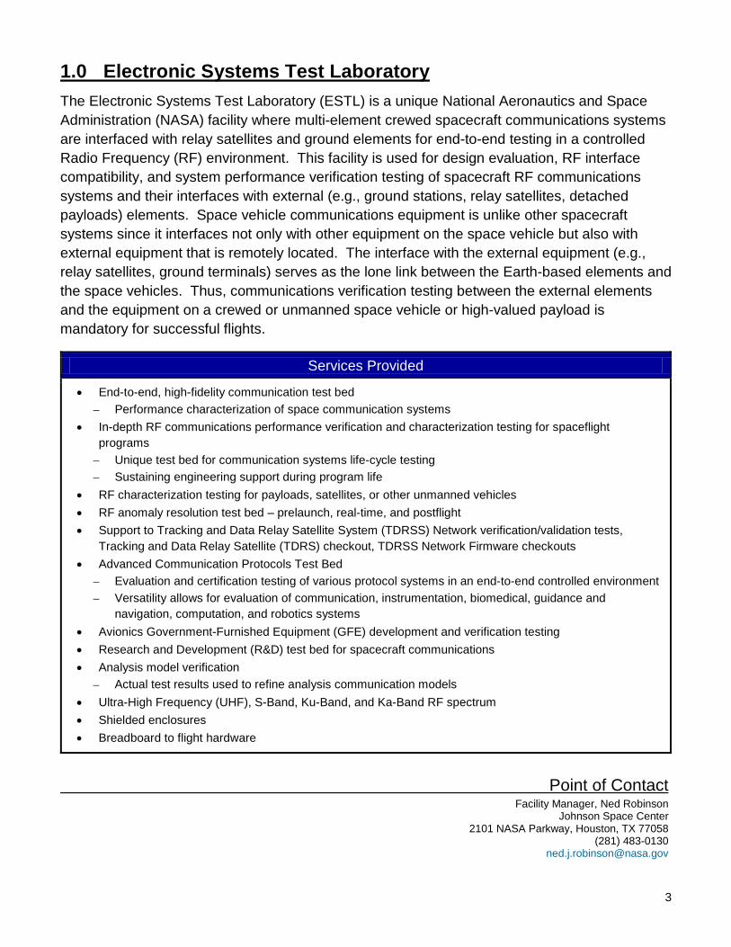
1.0 Electronic Systems Test Laboratory The Electronic Systems Test Laboratory (ESTL) is a unique National Aeronautics and Space Administration (NASA) facility where multi-element crewed spacecraft communications systems are interfaced with relay satellites and ground elements for end-to-end testing in a controlled Radio Frequency (RF) environment. This facility is used for design evaluation, RF interface compatibility, and system performance verification testing of spacecraft RF communications systems and their interfaces with external (e.g., ground stations, relay satellites, detached payloads) elements. Space vehicle communications equipment is unlike other spacecraft systems since it interfaces not only with other equipment on the space vehicle but also with external equipment that is remotely located. The interface with the external equipment (e.g., relay satellites, ground terminals) serves as the lone link between the Earth-based elements and the space vehicles. Thus, communications verification testing between the external elements and the equipment on a crewed or unmanned space vehicle or high-valued payload is mandatory for successful flights.
Services Provided
• End-to-end, high-fidelity communication test bed – Performance characterization of space communication systems
• In-depth RF communications performance verification and characterization testing for spaceflight programs
– Unique test bed for communication systems life-cycle testing – Sustaining engineering support during program life
• RF characterization testing for payloads, satellites, or other unmanned vehicles • RF anomaly resolution test bed – prelaunch, real-time, and postflight • Support to Tracking and Data Relay Satellite System (TDRSS) Network verification/validation tests,
Tracking and Data Relay Satellite (TDRS) checkout, TDRSS Network Firmware checkouts • Advanced Communication Protocols Test Bed
– Evaluation and certification testing of various protocol systems in an end-to-end controlled environment – Versatility allows for evaluation of communication, instrumentation, biomedical, guidance and
navigation, computation, and robotics systems • Avionics Government-Furnished Equipment (GFE) development and verification testing • Research and Development (R&D) test bed for spacecraft communications • Analysis model verification
– Actual test results used to refine analysis communication models • Ultra-High Frequency (UHF), S-Band, Ku-Band, and Ka-Band RF spectrum • Shielded enclosures • Breadboard to flight hardware
Point of Contact Facility Manager, Ned Robinson Johnson Space Center 2101 NASA Parkway, Houston, TX 77058 (281) 483-0130 [email protected]
4
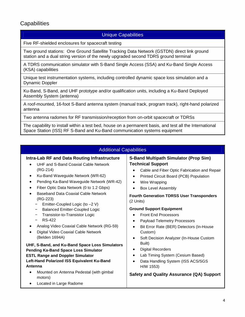
Capabilities
Unique Capabilities
Five RF-shielded enclosures for spacecraft testing
Two ground stations: One Ground Satellite Tracking Data Network (GSTDN) direct link ground station and a dual string version of the newly upgraded second TDRS ground terminal
A TDRS communication simulator with S-Band Single Access (SSA) and Ku-Band Single Access (KSA) capabilities
Unique test instrumentation systems, including controlled dynamic space loss simulation and a Dynamic Doppler
Ku-Band, S-Band, and UHF prototype and/or qualification units, including a Ku-Band Deployed Assembly System (antenna)
A roof-mounted, 16-foot S-Band antenna system (manual track, program track), right-hand polarized antenna
Two antenna radomes for RF transmission/reception from on-orbit spacecraft or TDRSs
The capability to install within a test bed, house on a permanent basis, and test all the International Space Station (ISS) RF S-Band and Ku-Band communication systems equipment
Additional Capabilities
Intra-Lab RF and Data Routing Infrastructure • UHF and S-Band Coaxial Cable Network
(RG-214) • Ku-Band Waveguide Network (WR-62) • Pending Ka-Band Waveguide Network (WR-42) • Fiber Optic Data Network (0 to 1.2 Gbps) • Baseband Data Coaxial Cable Network
(RG-223) − Emitter-Coupled Logic (to –2 V) − Balanced Emitter-Coupled Logic − Transistor-to-Transistor Logic − RS-422
• Analog Video Coaxial Cable Network (RG-59) • Digital Video Coaxial Cable Network
(Belden 1694A)
UHF, S-Band, and Ku-Band Space Loss Simulators Pending Ka-Band Space Loss Simulator ESTL Range and Doppler Simulator Left-Hand Polarized ISS Equivalent Ku-Band Antenna • Mounted on Antenna Pedestal (with gimbal
motors) • Located in Large Radome
S-Band Multipath Simulator (Prop Sim) Technical Support • Cable and Fiber Optic Fabrication and Repair • Printed Circuit Board (PCB) Population • Wire Wrapping • Box Level Assembly
Fourth Generation TDRSS User Transponders (2 Units)
Ground Support Equipment • Front End Processors • Payload Telemetry Processors • Bit Error Rate (BER) Detectors (In-House
Custom) • Soft Decision Analyzer (In-House Custom
Built) • Digital Recorders • Lab Timing System (Cesium Based) • Data Handling System (ISS ACS/SGS
H/W 1553)
Safety and Quality Assurance (QA) Support
5
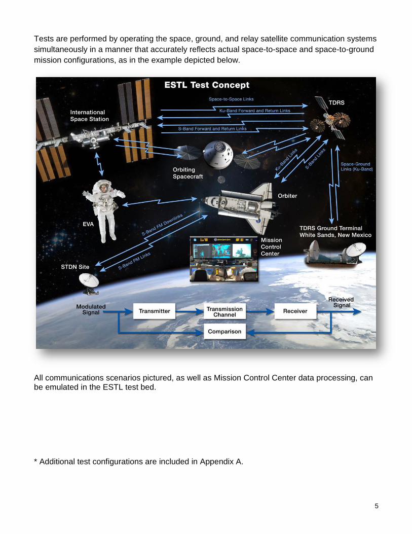
Tests are performed by operating the space, ground, and relay satellite communication systems simultaneously in a manner that accurately reflects actual space-to-space and space-to-ground mission configurations, as in the example depicted below.
All communications scenarios pictured, as well as Mission Control Center data processing, can be emulated in the ESTL test bed. * Additional test configurations are included in Appendix A.
6
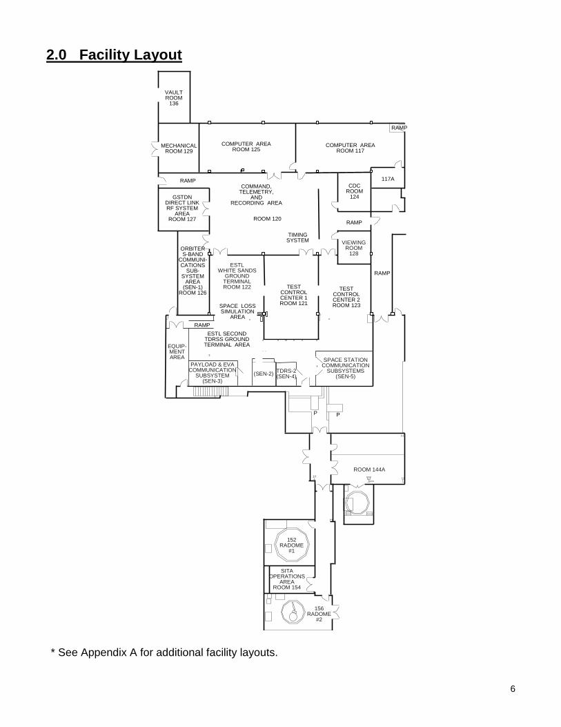
2.0 Facility Layout
TESTCONTROLCENTER 1ROOM 121
RAMP
RAMP
RAMP
RAMP
COMPUTER AREAROOM 117
COMPUTER AREAROOM 125
MECHANICALROOM 129
VAULTROOM
136
COMMAND,TELEMETRY,
ANDRECORDING AREA
TIMINGSYSTEM
ESTL SECONDTDRSS GROUNDTERMINAL AREA
117A
ORBITERS-BAND
COMMUNI-CATIONS
SUB-SYSTEM
AREA(SEN-1)
ROOM 126
GSTDNDIRECT LINKRF SYSTEM
AREAROOM 127
TESTCONTROLCENTER 2ROOM 123SPACE LOSS
SIMULATIONAREA
CDCROOM
124
ROOM 120
RAMP
UP
UP
ESTLWHITE SANDS
GROUNDTERMINALROOM 122
VIEWINGROOM
128
EQUIP-MENTAREA
PAYLOAD & EVACOMMUNICATION
SUBSYSTEM(SEN-3)
(SEN-2) TDRS-2(SEN-4)
SPACE STATIONCOMMUNICATION
SUBSYSTEMS(SEN-5)
ROOM 144A
152RADOME
#1
SITAOPERATIONS
AREAROOM 154
156RADOME
#2
* See Appendix A for additional facility layouts.
7
3.0 Safety and Health Safety is an integral part of the culture at NASA. Management, leadership, and employee involvement from all organizations are critical to the success of NASA’s safety program. In order to ensure personal safety and a safe test environment throughout the process, the requester shall furnish the facility with the information necessary to perform a hazard assessment of the test article. Additionally, while visiting the Johnson Space Center (JSC), the requester shall follow all facility-specific safety and health requirements. A facility safety briefing shall be provided to all personnel prior to the start of the test. The safety briefing will include a review of the ESTL safety rules, potential hazards, and emergency procedures.
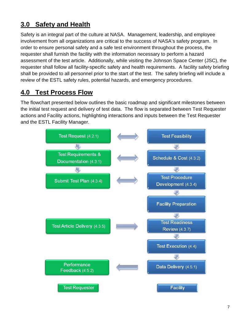
4.0 Test Process Flow The flowchart presented below outlines the basic roadmap and significant milestones between the initial test request and delivery of test data. The flow is separated between Test Requester actions and Facility actions, highlighting interactions and inputs between the Test Requester and the ESTL Facility Manager.
8
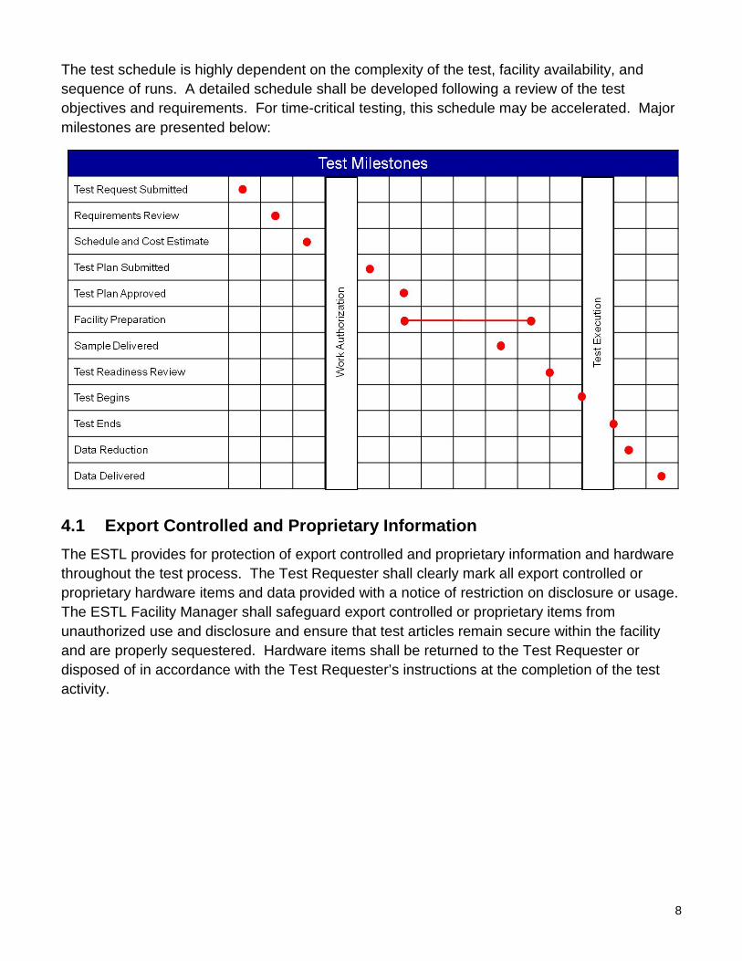
The test schedule is highly dependent on the complexity of the test, facility availability, and sequence of runs. A detailed schedule shall be developed following a review of the test objectives and requirements. For time-critical testing, this schedule may be accelerated. Major milestones are presented below:
4.1 Export Controlled and Proprietary Information The ESTL provides for protection of export controlled and proprietary information and hardware throughout the test process. The Test Requester shall clearly mark all export controlled or proprietary hardware items and data provided with a notice of restriction on disclosure or usage. The ESTL Facility Manager shall safeguard export controlled or proprietary items from unauthorized use and disclosure and ensure that test articles remain secure within the facility and are properly sequestered. Hardware items shall be returned to the Test Requester or disposed of in accordance with the Test Requester’s instructions at the completion of the test activity.
9
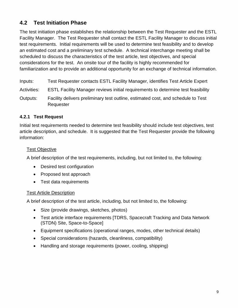
4.2 Test Initiation Phase The test initiation phase establishes the relationship between the Test Requester and the ESTL Facility Manager. The Test Requester shall contact the ESTL Facility Manager to discuss initial test requirements. Initial requirements will be used to determine test feasibility and to develop an estimated cost and a preliminary test schedule. A technical interchange meeting shall be scheduled to discuss the characteristics of the test article, test objectives, and special considerations for the test. An onsite tour of the facility is highly recommended for familiarization and to provide an additional opportunity for an exchange of technical information. Inputs: Test Requester contacts ESTL Facility Manager, identifies Test Article Expert
Activities: ESTL Facility Manager reviews initial requirements to determine test feasibility
Outputs: Facility delivers preliminary test outline, estimated cost, and schedule to Test Requester
4.2.1 Test Request
Initial test requirements needed to determine test feasibility should include test objectives, test article description, and schedule. It is suggested that the Test Requester provide the following information:
Test Objective
A brief description of the test requirements, including, but not limited to, the following:
• Desired test configuration • Proposed test approach • Test data requirements
Test Article Description
A brief description of the test article, including, but not limited to, the following:
• Size (provide drawings, sketches, photos) • Test article interface requirements [TDRS, Spacecraft Tracking and Data Network
(STDN) Site, Space-to-Space] • Equipment specifications (operational ranges, modes, other technical details) • Special considerations (hazards, cleanliness, compatibility) • Handling and storage requirements (power, cooling, shipping)
10
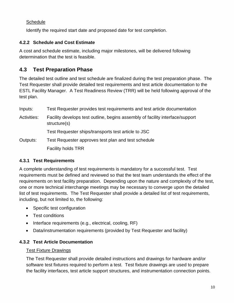
Schedule
Identify the required start date and proposed date for test completion.
4.2.2 Schedule and Cost Estimate
A cost and schedule estimate, including major milestones, will be delivered following determination that the test is feasible.
4.3 Test Preparation Phase The detailed test outline and test schedule are finalized during the test preparation phase. The Test Requester shall provide detailed test requirements and test article documentation to the ESTL Facility Manager. A Test Readiness Review (TRR) will be held following approval of the test plan. Inputs: Test Requester provides test requirements and test article documentation
Activities: Facility develops test outline, begins assembly of facility interface/support structure(s)
Test Requester ships/transports test article to JSC
Outputs: Test Requester approves test plan and test schedule
Facility holds TRR
4.3.1 Test Requirements
A complete understanding of test requirements is mandatory for a successful test. Test requirements must be defined and reviewed so that the test team understands the effect of the requirements on test facility preparation. Depending upon the nature and complexity of the test, one or more technical interchange meetings may be necessary to converge upon the detailed list of test requirements. The Test Requester shall provide a detailed list of test requirements, including, but not limited to, the following:
• Specific test configuration • Test conditions • Interface requirements (e.g., electrical, cooling, RF) • Data/instrumentation requirements (provided by Test Requester and facility)
4.3.2 Test Article Documentation
Test Fixture Drawings
The Test Requester shall provide detailed instructions and drawings for hardware and/or software test fixtures required to perform a test. Test fixture drawings are used to prepare the facility interfaces, test article support structures, and instrumentation connection points.
11
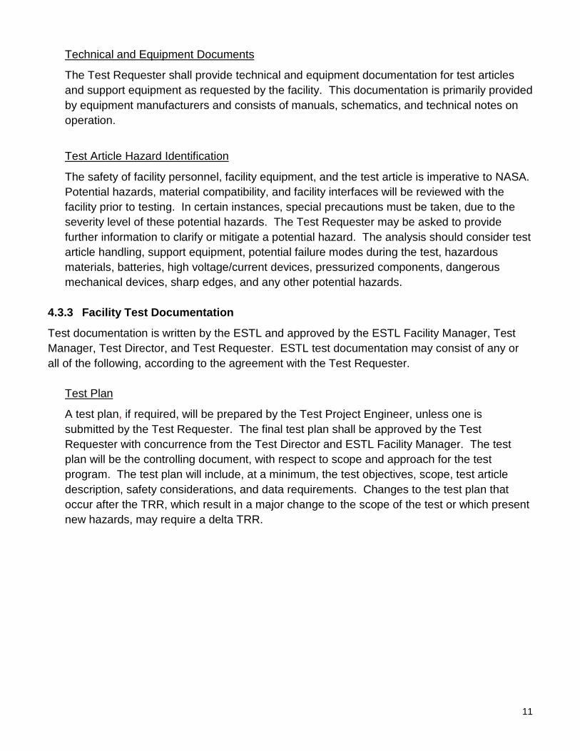
Technical and Equipment Documents
The Test Requester shall provide technical and equipment documentation for test articles and support equipment as requested by the facility. This documentation is primarily provided by equipment manufacturers and consists of manuals, schematics, and technical notes on operation.
Test Article Hazard Identification
The safety of facility personnel, facility equipment, and the test article is imperative to NASA. Potential hazards, material compatibility, and facility interfaces will be reviewed with the facility prior to testing. In certain instances, special precautions must be taken, due to the severity level of these potential hazards. The Test Requester may be asked to provide further information to clarify or mitigate a potential hazard. The analysis should consider test article handling, support equipment, potential failure modes during the test, hazardous materials, batteries, high voltage/current devices, pressurized components, dangerous mechanical devices, sharp edges, and any other potential hazards.
4.3.3 Facility Test Documentation
Test documentation is written by the ESTL and approved by the ESTL Facility Manager, Test Manager, Test Director, and Test Requester. ESTL test documentation may consist of any or all of the following, according to the agreement with the Test Requester.
Test Plan
A test plan, if required, will be prepared by the Test Project Engineer, unless one is submitted by the Test Requester. The final test plan shall be approved by the Test Requester with concurrence from the Test Director and ESTL Facility Manager. The test plan will be the controlling document, with respect to scope and approach for the test program. The test plan will include, at a minimum, the test objectives, scope, test article description, safety considerations, and data requirements. Changes to the test plan that occur after the TRR, which result in a major change to the scope of the test or which present new hazards, may require a delta TRR.
12
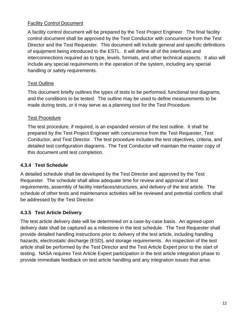
Facility Control Document
A facility control document will be prepared by the Test Project Engineer. The final facility control document shall be approved by the Test Conductor with concurrence from the Test Director and the Test Requester. This document will include general and specific definitions of equipment being introduced to the ESTL. It will define all of the interfaces and interconnections required as to type, levels, formats, and other technical aspects. It also will include any special requirements in the operation of the system, including any special handling or safety requirements.
Test Outline
This document briefly outlines the types of tests to be performed, functional test diagrams, and the conditions to be tested. The outline may be used to define measurements to be made during tests, or it may serve as a planning tool for the Test Procedure. Test Procedure
The test procedure, if required, is an expanded version of the test outline. It shall be prepared by the Test Project Engineer with concurrence from the Test Requester, Test Conductor, and Test Director. The test procedure includes the test objectives, criteria, and detailed test configuration diagrams. The Test Conductor will maintain the master copy of this document until test completion.
4.3.4 Test Schedule
A detailed schedule shall be developed by the Test Director and approved by the Test Requester. The schedule shall allow adequate time for review and approval of test requirements, assembly of facility interfaces/structures, and delivery of the test article. The schedule of other tests and maintenance activities will be reviewed and potential conflicts shall be addressed by the Test Director.
4.3.5 Test Article Delivery
The test article delivery date will be determined on a case-by-case basis. An agreed-upon delivery date shall be captured as a milestone in the test schedule. The Test Requester shall provide detailed handling instructions prior to delivery of the test article, including handling hazards, electrostatic discharge (ESD), and storage requirements. An inspection of the test article shall be performed by the Test Director and the Test Article Expert prior to the start of testing. NASA requires Test Article Expert participation in the test article integration phase to provide immediate feedback on test article handling and any integration issues that arise.
13
4.3.6 Test Readiness Review
A TRR will be held to ensure the completion of all necessary facility and test article activities prior to test execution. The TRR will include the following:
• Review of the test plan, test procedures, and other required test documentation • Confirmation of facility and test article readiness • Review of configuration records, including facility interface control documents, pressure
system certification, instrumentation calibration, and materials compatibility • Assurance that controls are in place to mitigate risks or hazards identified in the Test
Article Hazard Analysis • Verification that data acquisition and processing functions are in place to adequately
capture all critical data • Confirmation that multimedia coverage is adequate to provide recognition and
assessment of potential test anomalies Approval to proceed with test operations is granted by the Test Readiness Review Board (TRRB). The Facility Manager and Test Director shall ensure that all TRR actions have been accomplished prior to the start of the test. The TRRB shall convene 1 to 5 business days prior to the start of the test. TRRB participants shall include the following: NASA TRRB Chairman Test Article Expert (Appointed by Test Requester) Test Director Safety Engineer NASA Test Safety Officer Quality Engineer – if required by facility Radiation Safety Officer
4.4 Test Execution Phase NASA requires Test Requester participation in the testing activity. The Test Requester shall provide a Test Article Expert to verify that test setup and execution meet the stated objectives. The Test Article Expert also shall verify test article performance and approve requested test deviations during test operations. Inputs: Approval to begin testing received from TRRB
Activities: Facility completes facility buildup, Detailed Test Procedure
Facility conducts testing activity
Outputs: Test completed
14
4.4.1 Test Authority
The Test Director has the authority and responsibility to direct the test in accordance with the approved test plan and to terminate test activities per test rules when danger is imminent or test control cannot be maintained. The Test Director will ensure that positive actions are taken to halt any steps in the test procedure whenever unsafe or hazardous test conditions arise. The Test Director, with the concurrence of the Test Conductor and Test Article Expert, has the authority to terminate the test when sufficient data has been obtained to meet objectives or when objectives cannot be met. Test team personnel will accept directions only from the Test Director or designee.
4.4.2 Test Deviations
Changes to the test procedure shall be approved by the Test Article Expert with concurrence from the Test Conductor and Test Director. Deviations that result in a major change to the scope of the test or that present new hazards may require a delta TRR.
4.5 Test Closeout Phase Data shall be delivered to the Test Requester within an agreed-upon timeframe following completion of testing. The Test Requester shall notify the Test Director upon receipt of the data. Acceptance of the test data concludes the test activity. Inputs: Test completed
Activities: Facility ships/transports test article to Test Requester
Test Director delivers data to Test Requester
Outputs: Test Requester accepts data
Test Requester completes Customer Feedback form
4.5.1 Data Package
A data package shall be prepared by the Test Project Engineer, reviewed by the appropriate ESTL personnel, and submitted to the Test Requester. The data package will contain all of the raw and processed data recorded during the performance of the test. It will contain ESTL standard data sheets and plots, which may contain spectral plots, photographs, calculations, stripchart recordings, and other means of recording data, depending on data requirements defined by the Test Requester. A summary of the significant findings of the test shall also be included.
15
4.5.2 Customer Feedback
The ESTL requests feedback from our customers. Evaluation of the services we provide enables continued improvement to our process. A Customer Feedback form is included in Appendix D. You are encouraged to complete the Customer Feedback form and return it to the Test Director, following receipt of the test data. Your participation is greatly appreciated.
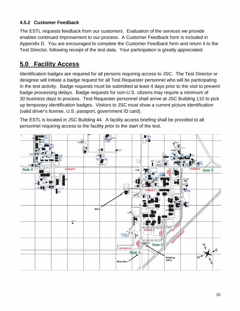
5.0 Facility Access Identification badges are required for all persons requiring access to JSC. The Test Director or designee will initiate a badge request for all Test Requester personnel who will be participating in the test activity. Badge requests must be submitted at least 4 days prior to the visit to prevent badge processing delays. Badge requests for non-U.S. citizens may require a minimum of 30 business days to process. Test Requester personnel shall arrive at JSC Building 110 to pick up temporary identification badges. Visitors to JSC must show a current picture identification (valid driver’s license, U.S. passport, government ID card).
The ESTL is located in JSC Building 44. A facility access briefing shall be provided to all personnel requiring access to the facility prior to the start of the test.
16
6.0 Roles and Responsibilities
Facility Manager – Responsible for the overall management, operation, safety, and scheduling of the ESTL.
Test Director – Has overall responsibility for all phases of the test process.
Test Requester – The client requesting performance of a test activity. The Test Requester is responsible for the test article and for providing a Test Article Expert.
Test Article Expert – A representative of the Test Requester with thorough knowledge of the test article and how it is to be operated in the test environment. The Test Article Expert also is responsible for approving the test plan and verifying that test objectives are met.
Test Conductor – Assigned under the authority of the Test Director to execute the test in accordance with the approved test plan.
Test Project Engineer – Responsible for the detailed planning of the test. This includes test planning, test procedures, the facility control document, and the data package.
Safety Engineer – Reviews the Test Article Hazard Checklist and the integrated hazard analysis for the test facility to identify any additional hazards that could result in injury to personnel.
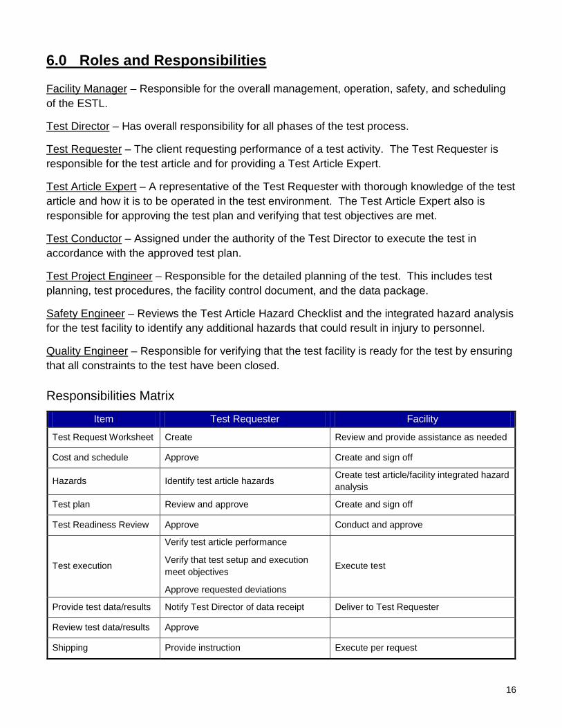
Quality Engineer – Responsible for verifying that the test facility is ready for the test by ensuring that all constraints to the test have been closed. Responsibilities Matrix
Item Test Requester Facility
Test Request Worksheet Create Review and provide assistance as needed
Cost and schedule Approve Create and sign off
Hazards Identify test article hazards Create test article/facility integrated hazard analysis
Test plan Review and approve Create and sign off
Test Readiness Review Approve Conduct and approve
Test execution
Verify test article performance
Verify that test setup and execution meet objectives
Approve requested deviations
Execute test
Provide test data/results Notify Test Director of data receipt Deliver to Test Requester
Review test data/results Approve
Shipping Provide instruction Execute per request
17
Acronyms
ACBSP Assembly Contingency Baseband Signal Processor
ACPTB Advanced Communication Protocols Test Bed
AOS Acquisition of Signal
AUAI ACS/UCS Audio Interface
BER Bit Error Rate
C3I Command, Control, Communication, and Intelligence
CCSDS Consultative Committee for Space Data Systems
DAT Digital Audio Tape
DEMPR Digital Ethernet Multiport Repeater
EMACS Equipment Monitor and Control System
ESD Electrostatic Discharge
ESTL Electronic Systems Test Laboratory
EVA Extravehicular Activity
FM Frequency Modulation
GFE Government-Furnished Equipment
GSTDN Ground Satellite Tracking Data Network
HRFM High Rate Frame Multiplexer
IEEE Institute of Electrical and Electronics Engineers
IP Internet Protocol
IRIG Inter-Range Instrumentation Group
ISS International Space Station
JSC Johnson Space Center
KSA Ku-Band Single Access
LDPC Low-Density Parity Check
LRU Line Replaceable Unit
MCC Mission Control Center
NASA National Aeronautics and Space Administration
NTSC National Television Standards Committee
PCB Printed Circuit Board
PTP Programmable Telemetry Processor
18
QA Quality Assurance
QOS Quality of Service
R&D Research and Development
RF Radio Frequency
SDI Serial Digital Interface
SEN Shielded Enclosure Number (Area)
SITA Satellite Interface Test Area
SLSA Space Loss Simulator Area
SSA S-Band Single Access
STDN Spacecraft Tracking and Data Network
TDRS Tracking and Data Relay Satellite
TDRSS Tracking and Data Relay Satellite System
TRR Test Readiness Review
TRRB Test Readiness Review Board
UHF Ultra-High Frequency
VoIP Voice Over Internet Protocol
19
Appendices A. Facility Configurations
B. Test Request Worksheet
C. Facility Equipment
D. Customer Feedback
20
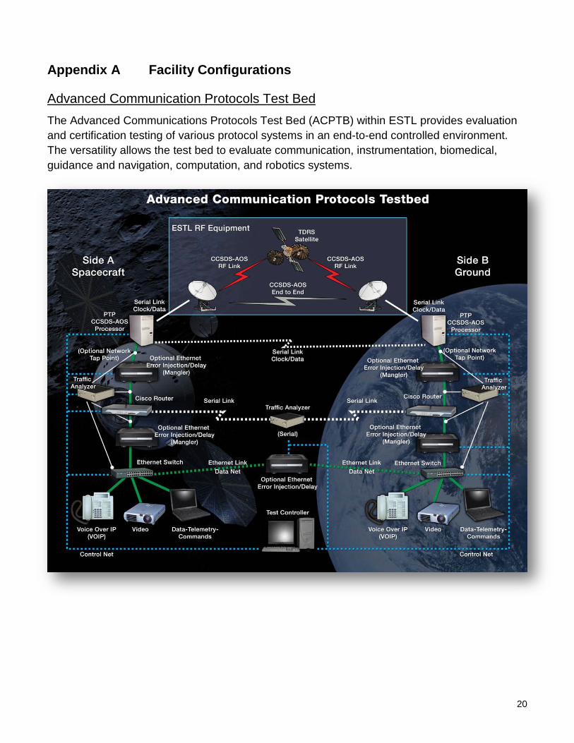
Appendix A Facility Configurations
Advanced Communication Protocols Test Bed The Advanced Communications Protocols Test Bed (ACPTB) within ESTL provides evaluation and certification testing of various protocol systems in an end-to-end controlled environment. The versatility allows the test bed to evaluate communication, instrumentation, biomedical, guidance and navigation, computation, and robotics systems.
21
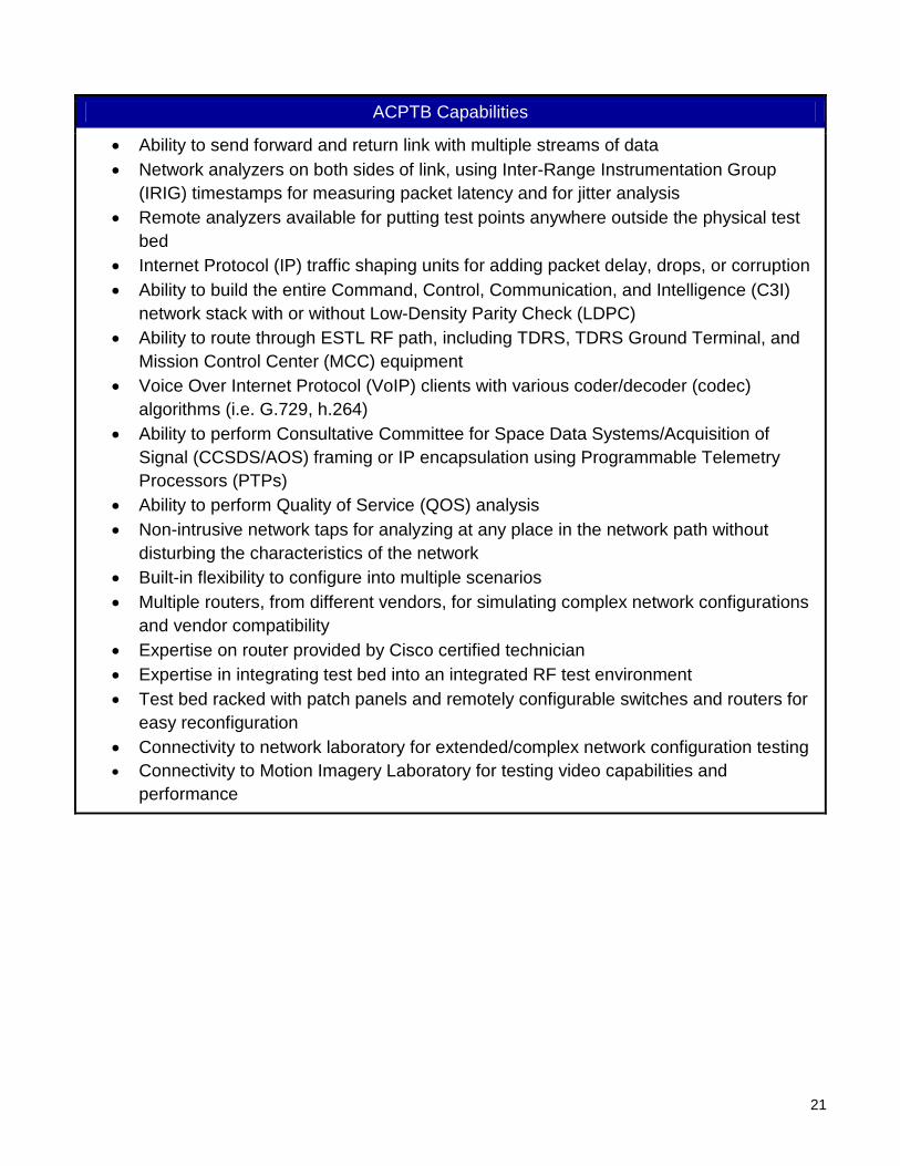
ACPTB Capabilities
• Ability to send forward and return link with multiple streams of data • Network analyzers on both sides of link, using Inter-Range Instrumentation Group
(IRIG) timestamps for measuring packet latency and for jitter analysis • Remote analyzers available for putting test points anywhere outside the physical test
bed • Internet Protocol (IP) traffic shaping units for adding packet delay, drops, or corruption • Ability to build the entire Command, Control, Communication, and Intelligence (C3I)
network stack with or without Low-Density Parity Check (LDPC) • Ability to route through ESTL RF path, including TDRS, TDRS Ground Terminal, and
Mission Control Center (MCC) equipment • Voice Over Internet Protocol (VoIP) clients with various coder/decoder (codec)
algorithms (i.e. G.729, h.264) • Ability to perform Consultative Committee for Space Data Systems/Acquisition of
Signal (CCSDS/AOS) framing or IP encapsulation using Programmable Telemetry Processors (PTPs)
• Ability to perform Quality of Service (QOS) analysis • Non-intrusive network taps for analyzing at any place in the network path without
disturbing the characteristics of the network • Built-in flexibility to configure into multiple scenarios • Multiple routers, from different vendors, for simulating complex network configurations
and vendor compatibility • Expertise on router provided by Cisco certified technician • Expertise in integrating test bed into an integrated RF test environment • Test bed racked with patch panels and remotely configurable switches and routers for
easy reconfiguration • Connectivity to network laboratory for extended/complex network configuration testing • Connectivity to Motion Imagery Laboratory for testing video capabilities and
performance
22
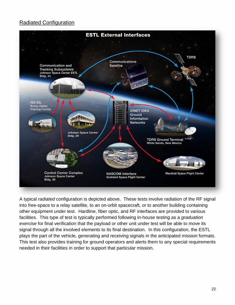
Radiated Configuration
A typical radiated configuration is depicted above. These tests involve radiation of the RF signal into free-space to a relay satellite, to an on-orbit spacecraft, or to another building containing other equipment under test. Hardline, fiber optic, and RF interfaces are provided to various facilities. This type of test is typically performed following in-house testing as a graduation exercise for final verification that the payload or other unit under test will be able to move its signal through all the involved elements to its final destination. In this configuration, the ESTL plays the part of the vehicle, generating and receiving signals in the anticipated mission formats. This test also provides training for ground operators and alerts them to any special requirements needed in their facilities in order to support that particular mission.
23
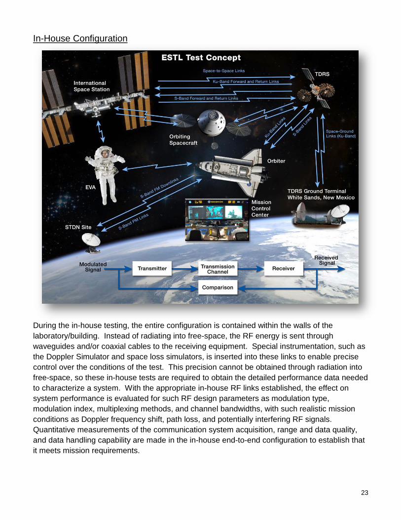
In-House Configuration
During the in-house testing, the entire configuration is contained within the walls of the laboratory/building. Instead of radiating into free-space, the RF energy is sent through waveguides and/or coaxial cables to the receiving equipment. Special instrumentation, such as the Doppler Simulator and space loss simulators, is inserted into these links to enable precise control over the conditions of the test. This precision cannot be obtained through radiation into free-space, so these in-house tests are required to obtain the detailed performance data needed to characterize a system. With the appropriate in-house RF links established, the effect on system performance is evaluated for such RF design parameters as modulation type, modulation index, multiplexing methods, and channel bandwidths, with such realistic mission conditions as Doppler frequency shift, path loss, and potentially interfering RF signals. Quantitative measurements of the communication system acquisition, range and data quality, and data handling capability are made in the in-house end-to-end configuration to establish that it meets mission requirements.
24
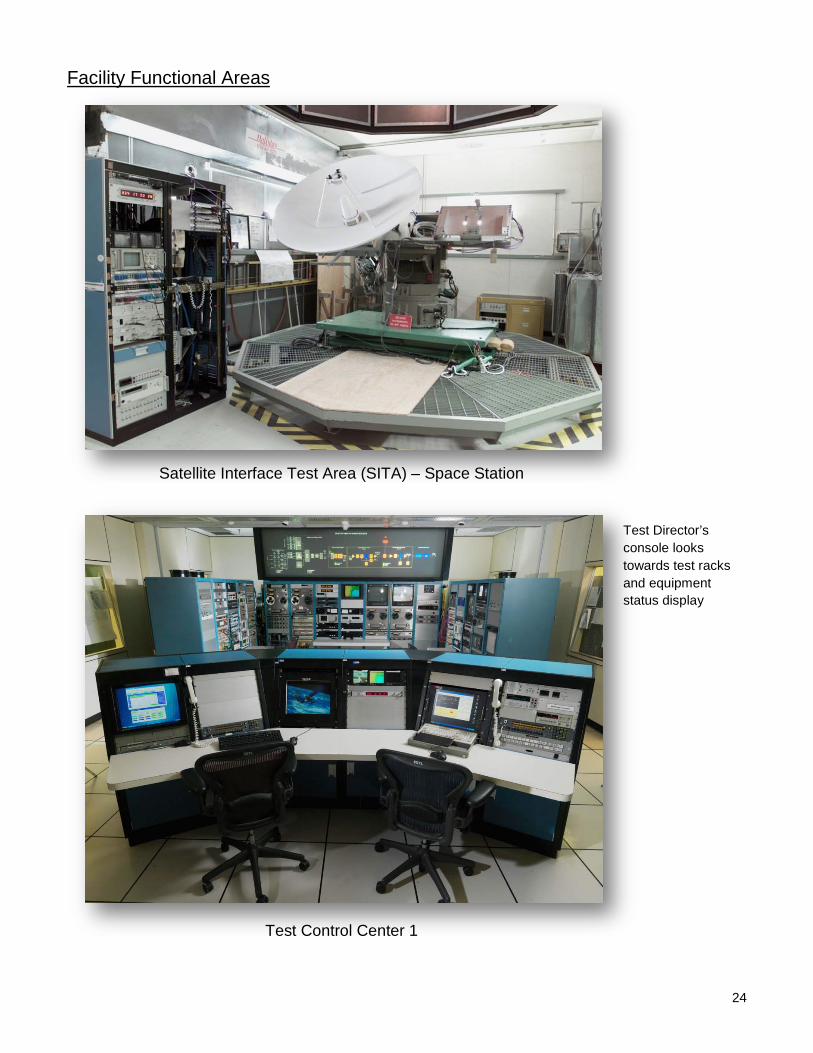
Facility Functional Areas
Satellite Interface Test Area (SITA) – Space Station
Test Control Center 1
Test Director’s console looks towards test racks and equipment status display
25
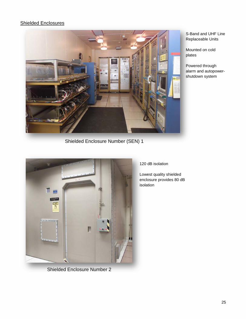
Shielded Enclosures
Shielded Enclosure Number (SEN) 1
S-Band and UHF Line Replaceable Units Mounted on cold plates Powered through alarm and autopower-shutdown system
Shielded Enclosure Number 2
120 dB isolation Lowest quality shielded enclosure provides 80 dB isolation
26
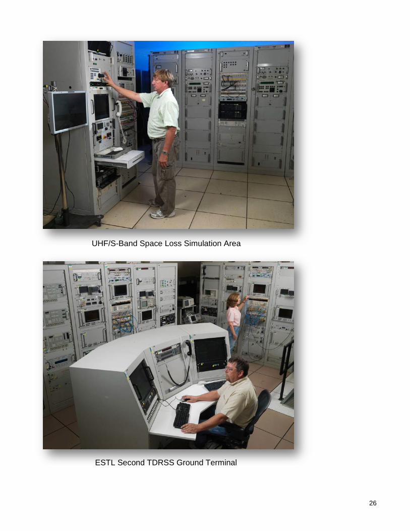
UHF/S-Band Space Loss Simulation Area
ESTL Second TDRSS Ground Terminal
27
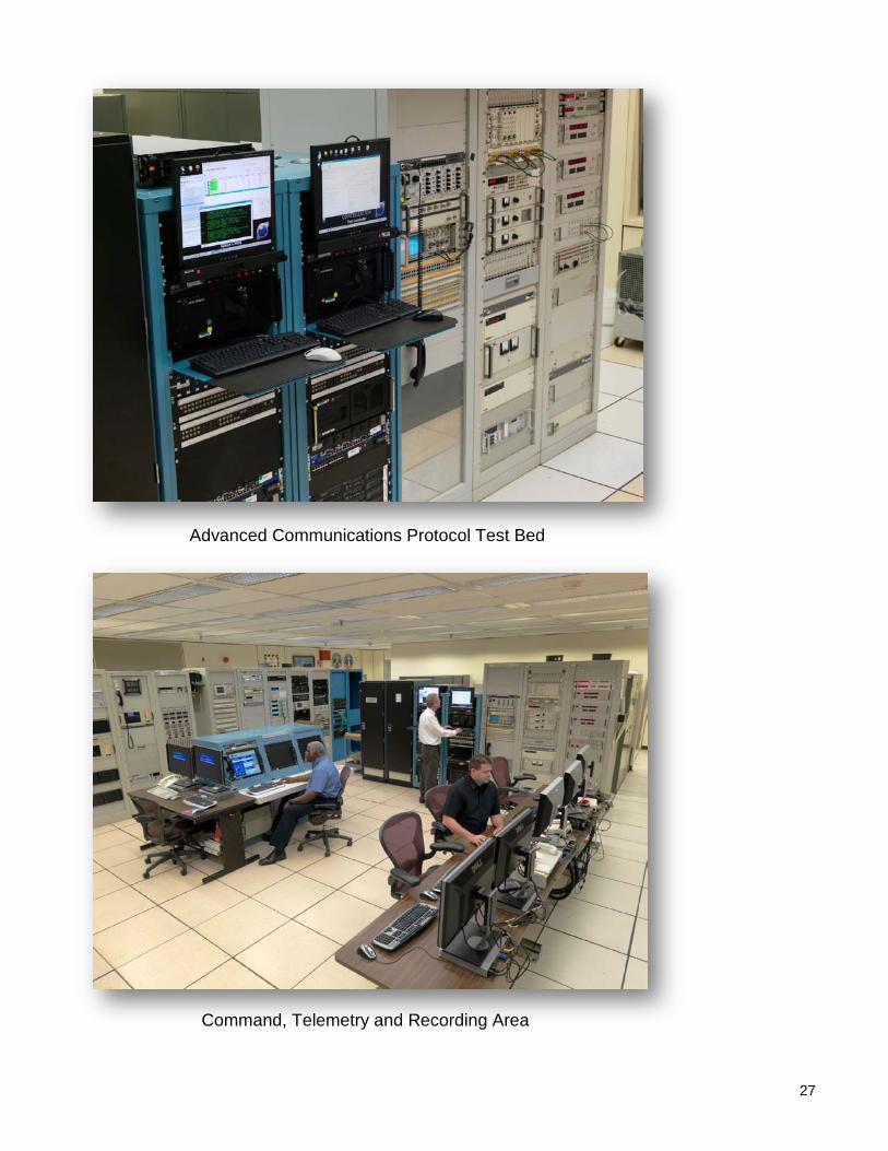
Advanced Communications Protocol Test Bed
Command, Telemetry and Recording Area
28
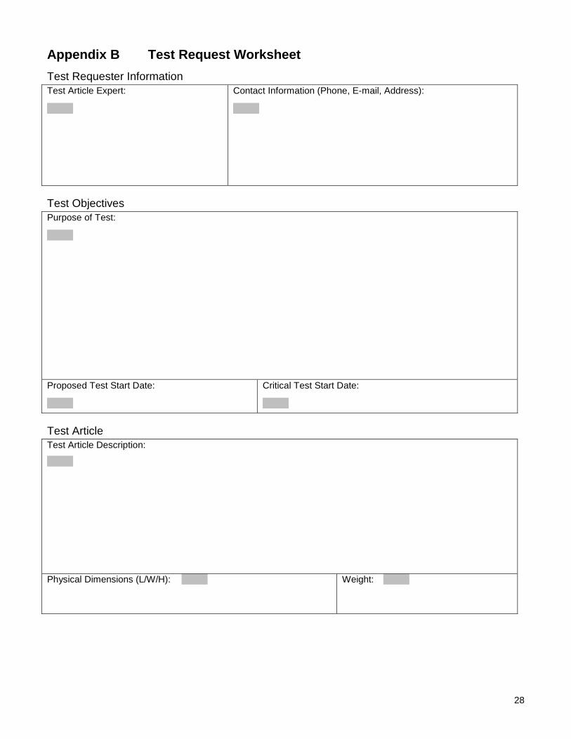
Appendix B Test Request Worksheet Test Requester Information Test Article Expert:
Contact Information (Phone, E-mail, Address):
Test Objectives Purpose of Test:
Proposed Test Start Date:
Critical Test Start Date:
Test Article Test Article Description:
Physical Dimensions (L/W/H):
Weight:
EQUPMENT LOCK LID
29
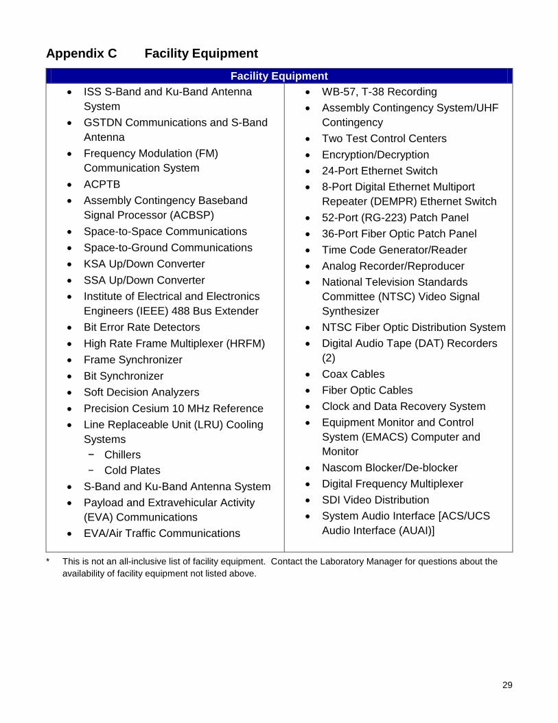
Appendix C Facility Equipment Facility Equipment
• ISS S-Band and Ku-Band Antenna System
• GSTDN Communications and S-Band Antenna
• Frequency Modulation (FM) Communication System
• ACPTB • Assembly Contingency Baseband
Signal Processor (ACBSP) • Space-to-Space Communications • Space-to-Ground Communications • KSA Up/Down Converter • SSA Up/Down Converter • Institute of Electrical and Electronics
Engineers (IEEE) 488 Bus Extender • Bit Error Rate Detectors • High Rate Frame Multiplexer (HRFM) • Frame Synchronizer • Bit Synchronizer • Soft Decision Analyzers • Precision Cesium 10 MHz Reference • Line Replaceable Unit (LRU) Cooling
Systems − Chillers − Cold Plates
• S-Band and Ku-Band Antenna System • Payload and Extravehicular Activity
(EVA) Communications • EVA/Air Traffic Communications
• WB-57, T-38 Recording • Assembly Contingency System/UHF
Contingency • Two Test Control Centers • Encryption/Decryption • 24-Port Ethernet Switch • 8-Port Digital Ethernet Multiport
Repeater (DEMPR) Ethernet Switch • 52-Port (RG-223) Patch Panel • 36-Port Fiber Optic Patch Panel • Time Code Generator/Reader • Analog Recorder/Reproducer • National Television Standards
Committee (NTSC) Video Signal Synthesizer
• NTSC Fiber Optic Distribution System • Digital Audio Tape (DAT) Recorders
(2) • Coax Cables • Fiber Optic Cables • Clock and Data Recovery System • Equipment Monitor and Control
System (EMACS) Computer and Monitor
• Nascom Blocker/De-blocker • Digital Frequency Multiplexer • SDI Video Distribution • System Audio Interface [ACS/UCS
Audio Interface (AUAI)]
* This is not an all-inclusive list of facility equipment. Contact the Laboratory Manager for questions about the availability of facility equipment not listed above.
30
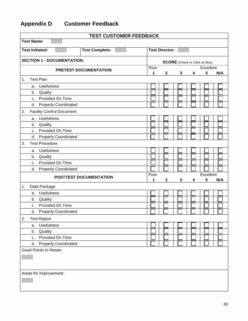
Appendix D Customer Feedback
TEST CUSTOMER FEEDBACK Test Name:
Test Initiated: Test Complete: Test Director:
SECTION 1 - DOCUMENTATION: SCORE (Check or Click on Box) PRETEST DOCUMENTATION Poor Excellent
1 2 3 4 5 N/A 1. Test Plan
a. Usefulness b. Quality c. Provided On Time d. Properly Coordinated
2. Facility Control Document
a. Usefulness b. Quality c. Provided On Time d. Properly Coordinated
3. Test Procedure
a. Usefulness b. Quality c. Provided On Time d. Properly Coordinated
POSTTEST DOCUMENTATION Poor Excellent 1 2 3 4 5 N/A
1. Data Package a. Usefulness b. Quality c. Provided On Time d. Properly Coordinated
2. Test Report a. Usefulness b. Quality c. Provided On Time d. Properly Coordinated
Good Points to Retain:
Areas for Improvement:
31
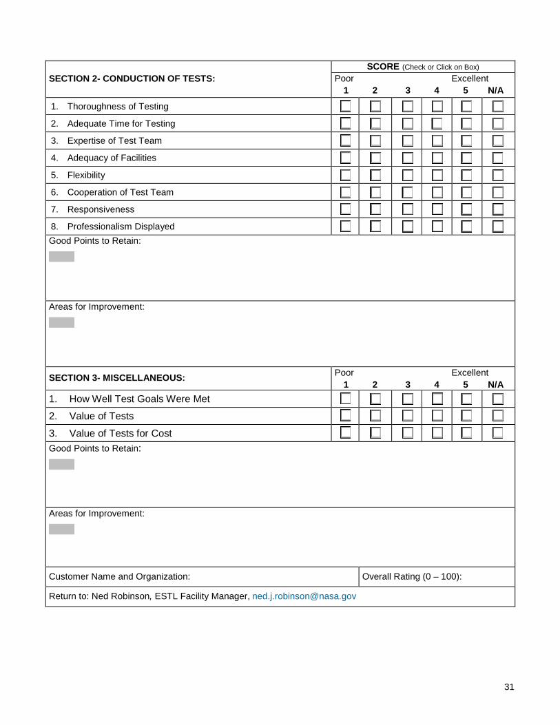
SECTION 2- CONDUCTION OF TESTS: SCORE (Check or Click on Box)
Poor Excellent 1 2 3 4 5 N/A
1. Thoroughness of Testing
2. Adequate Time for Testing
3. Expertise of Test Team
4. Adequacy of Facilities
5. Flexibility
6. Cooperation of Test Team
7. Responsiveness
8. Professionalism Displayed Good Points to Retain:
Areas for Improvement:
SECTION 3- MISCELLANEOUS: Poor Excellent 1 2 3 4 5 N/A
1. How Well Test Goals Were Met
2. Value of Tests
3. Value of Tests for Cost
Good Points to Retain:
Areas for Improvement:
Customer Name and Organization: Overall Rating (0 – 100):
Return to: Ned Robinson, ESTL Facility Manager, [email protected]