Electronic supplementary information · Electronic supplementary information Enhanced polysulphide...
12
S1 Electronic supplementary information Enhanced polysulphide redox reaction using a RuO2 nanoparticle-decorated mesoporous carbon as functional separator coating for advanced lithium- sulphur batteries J. Balach,* a T. Jaumann, ab S. Mühlenhoff, a J. Eckert‡ ab and L. Giebeler ab a Leibniz Institute for Solid State and Materials Research (IFW) Dresden e.V., Institute for Complex Materials, Helmholtzstraße 20, D-01069 Dresden, Germany. b Technische Universität Dresden, Institut für Werkstoffwissenschaft, Helmholtzstraße 7, D- 01069 Dresden, Germany. ‡ Present address: Erich Schmid Institute of Materials Science, Austrian Academy of Sciences and Department of Materials Physics, Montanuniversität Leoben, Jahnstr. 12, A-8700 Leoben, Austria. *Corresponding Author E-mail address: [email protected] Electronic Supplementary Material (ESI) for Chemical Communications. This journal is © The Royal Society of Chemistry 2016
-
Upload
phungtuong -
Category
Documents
-
view
219 -
download
0
Transcript of Electronic supplementary information · Electronic supplementary information Enhanced polysulphide...
S1
Electronic supplementary information
Enhanced polysulphide redox reaction using a RuO2 nanoparticle-decorated
mesoporous carbon as functional separator coating for advanced lithium-
sulphur batteries
J. Balach,*a T. Jaumann,ab S. Mühlenhoff,a J. Eckert‡ab and L. Giebelerab
aLeibniz Institute for Solid State and Materials Research (IFW) Dresden e.V., Institute for
Complex Materials, Helmholtzstraße 20, D-01069 Dresden, Germany.
bTechnische Universität Dresden, Institut für Werkstoffwissenschaft, Helmholtzstraße 7, D-
01069 Dresden, Germany.
‡ Present address: Erich Schmid Institute of Materials Science, Austrian Academy of Sciences and
Department of Materials Physics, Montanuniversität Leoben, Jahnstr. 12, A-8700 Leoben, Austria.
*Corresponding Author
E-mail address: [email protected]
Electronic Supplementary Material (ESI) for Chemical Communications.This journal is © The Royal Society of Chemistry 2016
S2
Experimental details
Chemicals
Ruthenium(III) chloride hydrate (RuCl3·nH2O), ruthenium(IV) oxide nanoparticles (RuO2, 99.9
wt%), Ludox HS-40 (40 wt%, 12 nm SiO2 nanoparticles), elemental sulphur (S, 99.98 wt%),
acacia-derived gum arabic (GA), N-methyl-2-pyrrolidone (NMP, 99 wt%), 1,3-dioxolane (DOL,
99.8 wt%, anhydrous) and 1,2-dimethoxyethane (DME, 99.5 wt%, anhydrous) were purchased
from Sigma-Aldrich. Super P carbon (SP), lithium bis(trifluoromethylsulfonyl)imide salt
(LiN(CF3SO2)2, Li-TFSI) polyvinylidene difluoride (PVDF, Solef 21216) and hydrofluoric acid
(HF, 40 wt%) as well as lithium nitrate (LiNO3, >99.995 wt%) were purchased from TIMCAL,
BASF, Solvay and Merck, respectively. All chemicals were used as received, except Li-TFSI and
LiNO3 which were dried at 100 °C under vacuum for 20 h afore.
Synthesis of MPC and RuO2-MPC composite
The mesoporous carbon (MPC) used as a RuO2-support material was prepared via SiO2-
templated casting route following our previous report.1 Here, a resorcinol-formaldehyde polymer
was used as a carbon precursor and the weight ratio of SiO2 to resorcinol was 2.
The RuO2-MPC composite was synthesised by a facile impregnation-hydrothermal oxidation of
RuCl3·nH2O at 200 °C under air, using a modified version of previous works.2, 3 In a typically
procedure, 400 mg of MPC was dispersed in 100 mL of deionized water by ultrasonication for 1
h; then 200 mg of RuCl3·nH2O in 10 ml of deionized water was added to the MPC dispersion. At
this point, the pH value of the above mixture was adjusted to 7 using NaOH 0.1 M solution and
kept it under vigorous stirring for 15 h. After reaction, the suspension was separated by filtration
and repeatedly washed with deionized water, then dried at 80 °C for 20 h and finally heated at 200
°C for 6 h using a heating ramp of 5 °C min–1.
S3
Hybrid separator fabrication
A straightforward modification of the commercially used Celgard polypropylene separator
(Celgard 2500) was carried out by casting shaker-milled RuO2-MPC composite slurry, containing
90 wt% of the composite material and 10 wt% of the PVDF binder in NMP, on one side of the
polypropylene separator using the doctor blade method. In a similar procedure, the SP-MPC-
coated separator was prepared using a carbon slurry containing MPC, SP and PVDF binder
(65:25:10 wt%). The coated separators were dried at 50 °C for 20 h and then cut it into circular
disks of 16 mm. The thickness and the added mass of the coatings were, respectively, ≈16 µm and
≈0.3 mg cm–2.
Pure sulphur cathode fabrication
The pure sulphur cathode in this research indicates that the active material is elemental sulphur
but not sulphur-based composites. A simple pure sulphur cathode was prepared by shaker-milling
elemental sulphur, SP and GA binder4 (70:20:10 wt%) in deionized water to form a homogeneous
mixture and then casting the slurry on an Al current collector by the doctor blade method. The
cathode was dried at 60 ºC and 80 ºC for, respectively, 20 h and 2 h and afterwards punched into
circular disks of 12 mm. The areal sulphur loading of the cathode is ≈2.0 mg cm–2. In this work,
the pure sulphur cathode refers to a simple-designed sulphur cathode prepared with elemental
sulphur as the active material instead of a sulphur-carbon composite cathode.5
Electrochemical testing
Lithium–sulphur cells were assembled into CR2025 coin-type cells in an Ar-filled glove box
with lithium metal foil (Chempur, 13 mm, 250 μm thick) as anode material and reference electrode
at the same moment. The electrolyte contains 1 M Li-TFSI and 0.25 M LiNO3 as additive in a 1:1
S4
volume ratio of DOL and DME. Celgard 2500 (16 mm, 25 μm thick) was used as pristine separator.
The hybrid separators were placed into the cell with the carbon layer oriented towards the cathode.
Cells were galvanostatically discharged and charged between the potential windows of 1.8–2.6
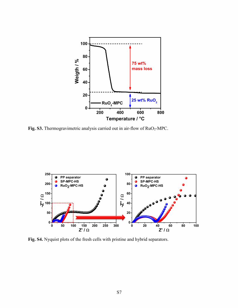
V at 25 °C using a BaSyTec Cell Test System (CTS). Electrochemical impedance spectroscopy
(EIS) measurements were carried out using a VMP3 potentiostat (Bio-Logic) between 200 KHz
and 100 mHz using an AC voltage amplitude of 5 mV at the open-circuit voltage of the cells. The
cyclic voltammograms were recorded at a scan rate of 0.05 mV s −1 between 1.8 and 2.8 V. The
combined cycling performance test consists of 10 cycles at a current rate of 0.1 C (1 C = 1672 mA
g–1) followed by 90 and 200 cycles at 0.2 and 0.5 C, respectively. The calculation of specific
discharging capacities is based on the mass of elemental sulphur while the reported values of the
Coulombic efficiency and the degradation rate per cycle are the average values acquired from the
corresponding data at 0.2 and 0.5 C (Table S3, ESI†).
Characterisation
A FEI Tecnai F30 transmission electron microscope (TEM) equipped with a field emission gun
(FEG) working at 300 kV was used for high-resolution imaging of the mesoporous carbons. The
morphology of the RuO2-MPC and the hybrid separators were examined using a Gemini 1530
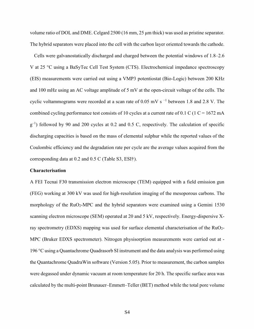
scanning electron microscope (SEM) operated at 20 and 5 kV, respectively. Energy-dispersive X-
ray spectrometry (EDXS) mapping was used for surface elemental characterisation of the RuO2-
MPC (Bruker EDXS spectrometer). Nitrogen physisorption measurements were carried out at -
196 °C using a Quantachrome Quadrasorb SI instrument and the data analysis was performed using
the Quantachrome QuadraWin software (Version 5.05). Prior to measurement, the carbon samples
were degassed under dynamic vacuum at room temperature for 20 h. The specific surface area was
calculated by the multi-point Brunauer–Emmett–Teller (BET) method while the total pore volume
S5
was determined at a relative pressure of p/p0 ≈ 0.98. The pore size distribution was obtained using
the Quenched Solid Density Functional Theory (QSDFT) equilibrium model. The reported
micropore volume is the cumulative pore volume at a diameter of 2 nm obtained from the QSDFT
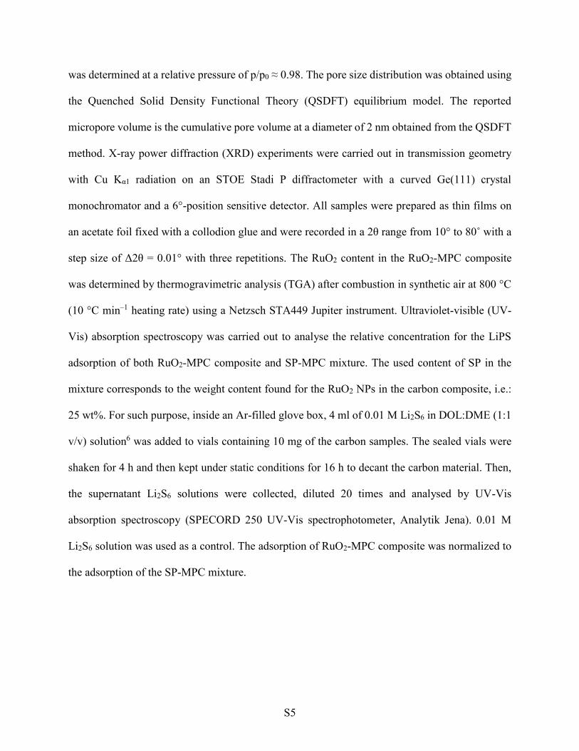
method. X-ray power diffraction (XRD) experiments were carried out in transmission geometry
with Cu Kα1 radiation on an STOE Stadi P diffractometer with a curved Ge(111) crystal
monochromator and a 6°-position sensitive detector. All samples were prepared as thin films on
an acetate foil fixed with a collodion glue and were recorded in a 2θ range from 10° to 80˚ with a
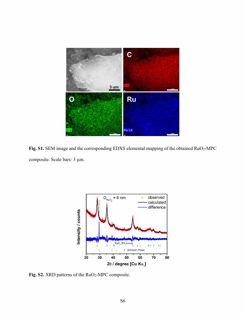
step size of Δ2θ = 0.01° with three repetitions. The RuO2 content in the RuO2-MPC composite
was determined by thermogravimetric analysis (TGA) after combustion in synthetic air at 800 °C
(10 °C min–1 heating rate) using a Netzsch STA449 Jupiter instrument. Ultraviolet-visible (UV-
Vis) absorption spectroscopy was carried out to analyse the relative concentration for the LiPS
adsorption of both RuO2-MPC composite and SP-MPC mixture. The used content of SP in the
mixture corresponds to the weight content found for the RuO2 NPs in the carbon composite, i.e.:
25 wt%. For such purpose, inside an Ar-filled glove box, 4 ml of 0.01 M Li2S6 in DOL:DME (1:1
v/v) solution6 was added to vials containing 10 mg of the carbon samples. The sealed vials were
shaken for 4 h and then kept under static conditions for 16 h to decant the carbon material. Then,
the supernatant Li2S6 solutions were collected, diluted 20 times and analysed by UV-Vis
absorption spectroscopy (SPECORD 250 UV-Vis spectrophotometer, Analytik Jena). 0.01 M
Li2S6 solution was used as a control. The adsorption of RuO2-MPC composite was normalized to
the adsorption of the SP-MPC mixture.
S6
Fig. S1. SEM image and the corresponding EDXS elemental mapping of the obtained RuO2-MPC
composite. Scale bars: 3 µm.
Fig. S2. XRD patterns of the RuO2-MPC composite.
S7
Fig. S3. Thermogravimetric analysis carried out in air-flow of RuO2-MPC.
Fig. S4. Nyquist plots of the fresh cells with pristine and hybrid separators.
S8
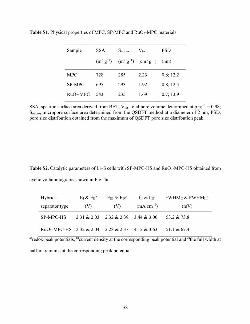
Table S1. Physical properties of MPC, SP-MPC and RuO2-MPC materials.
Sample SSA
(m2 g–1)
Smicro
(m2 g–1)
Vtot
(cm3 g–1)
PSD
(nm)
MPC 728 285 2.23 0.8; 12.2
SP-MPC 695 293 1.92 0.8; 12.4
RuO2-MPC 543 235 1.69 0.7; 13.9
SSA, specific surface area derived from BET; Vtot, total pore volume determined at p p0–1 = 0.98;
Smicro, micropore surface area determined from the QSDFT method at a diameter of 2 nm; PSD,
pore size distribution obtained from the maximum of QSDFT pore size distribution peak.
Table S2. Catalytic parameters of Li–S cells with SP-MPC-HS and RuO2-MPC-HS obtained from
cyclic voltammograms shown in Fig. 4a.
Hybrid
separator type
EI & EIIa
(V)
EIII & EIVa
(V)
III & IIIIb
(mA cm–2)
FWHMII & FWHMIIIc
(mV)
SP-MPC-HS 2.31 & 2.03 2.32 & 2.39 3.44 & 3.00 53.2 & 73.8
RuO2-MPC-HS 2.32 & 2.04 2.28 & 2.37 4.12 & 3.63 51.1 & 67.4
a)redox peak potentials, b)current density at the corresponding peak potential and c)the full width at
half-maximums at the corresponding peak potential.
S9
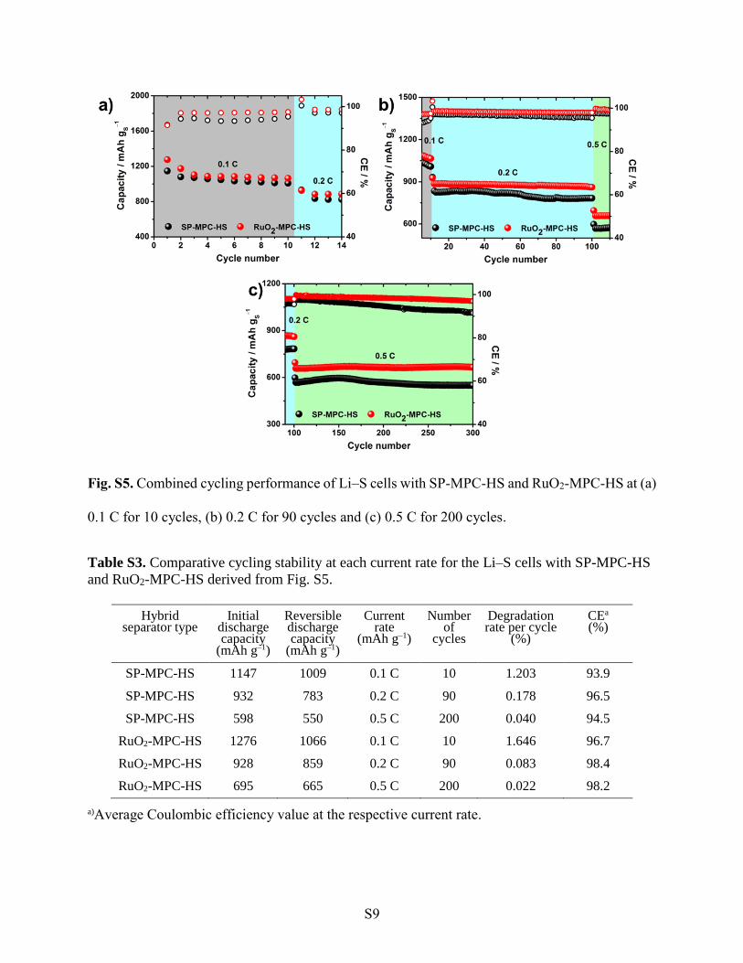
Fig. S5. Combined cycling performance of Li–S cells with SP-MPC-HS and RuO2-MPC-HS at (a)
0.1 C for 10 cycles, (b) 0.2 C for 90 cycles and (c) 0.5 C for 200 cycles.
Table S3. Comparative cycling stability at each current rate for the Li–S cells with SP-MPC-HS
and RuO2-MPC-HS derived from Fig. S5.
Hybrid separator type
Initial discharge capacity
(mAh g–1)
Reversible discharge capacity
(mAh g–1)
Current rate
(mAh g–1)
Number of
cycles
Degradation rate per cycle
(%)
CEa (%)
SP-MPC-HS 1147 1009 0.1 C 10 1.203 93.9
SP-MPC-HS 932 783 0.2 C 90 0.178 96.5
SP-MPC-HS 598 550 0.5 C 200 0.040 94.5
RuO2-MPC-HS 1276 1066 0.1 C 10 1.646 96.7
RuO2-MPC-HS 928 859 0.2 C 90 0.083 98.4
RuO2-MPC-HS 695 665 0.5 C 200 0.022 98.2
a)Average Coulombic efficiency value at the respective current rate.
S10
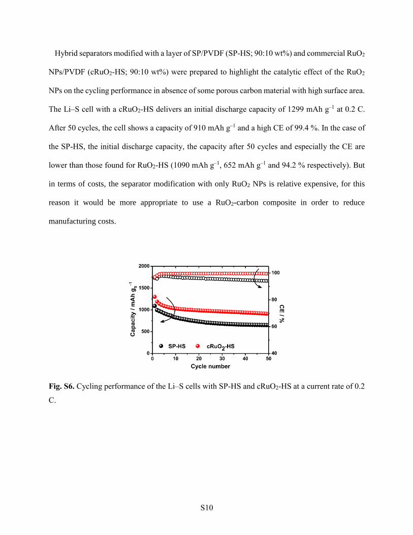
Hybrid separators modified with a layer of SP/PVDF (SP-HS; 90:10 wt%) and commercial RuO2
NPs/PVDF (cRuO2-HS; 90:10 wt%) were prepared to highlight the catalytic effect of the RuO2
NPs on the cycling performance in absence of some porous carbon material with high surface area.
The Li–S cell with a cRuO2-HS delivers an initial discharge capacity of 1299 mAh g–1 at 0.2 C.
After 50 cycles, the cell shows a capacity of 910 mAh g–1 and a high CE of 99.4 %. In the case of
the SP-HS, the initial discharge capacity, the capacity after 50 cycles and especially the CE are
lower than those found for RuO2-HS (1090 mAh g–1, 652 mAh g–1 and 94.2 % respectively). But
in terms of costs, the separator modification with only RuO2 NPs is relative expensive, for this
reason it would be more appropriate to use a RuO2-carbon composite in order to reduce
manufacturing costs.
Fig. S6. Cycling performance of the Li–S cells with SP-HS and cRuO2-HS at a current rate of 0.2
C.
S11
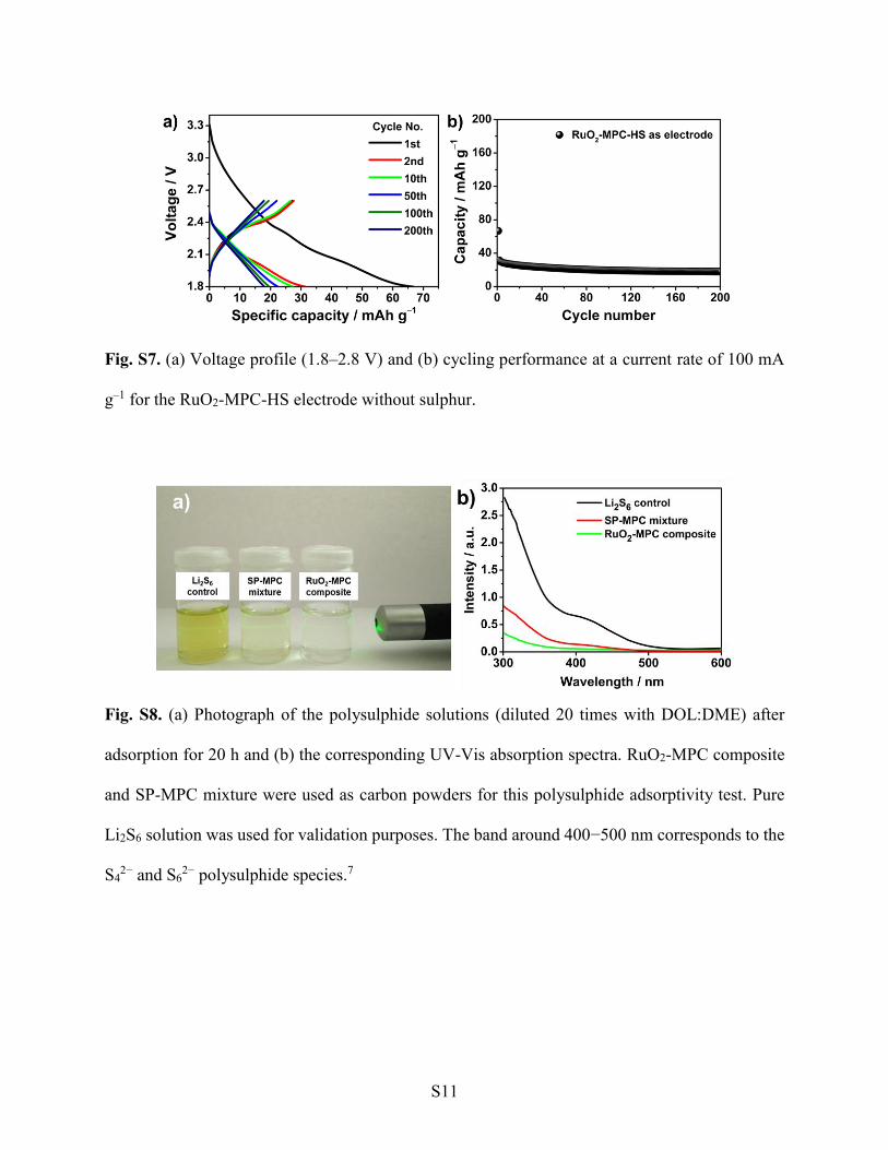
Fig. S7. (a) Voltage profile (1.8–2.8 V) and (b) cycling performance at a current rate of 100 mA
g–1 for the RuO2-MPC-HS electrode without sulphur.
Fig. S8. (a) Photograph of the polysulphide solutions (diluted 20 times with DOL:DME) after
adsorption for 20 h and (b) the corresponding UV-Vis absorption spectra. RuO2-MPC composite
and SP-MPC mixture were used as carbon powders for this polysulphide adsorptivity test. Pure
Li2S6 solution was used for validation purposes. The band around 400−500 nm corresponds to the
S42− and S6
2− polysulphide species.7
S12
References
1. J. Balach, T. Jaumann, M. Klose, S. Oswald, J. Eckert and L. Giebeler, J. Phys. Chem. C,
2015, 119, 4580.
2. R.-R. Bi, X.-L. Wu, F.-F. Cao, L.-Y. Jiang, Y.-G. Guo and L.-J. Wan, J. Phys. Chem. C,
2010, 114, 2448.
3. J. Cruz, V. Baglio, S. Siracusano, V. Antonucci, A. Aricò, R. Ornelas, L. Ortiz-Frade, G.
Osorio-Monreal, S. Duron-Torres and L. Arriaga, Int. J. Electrochem. Sci, 2011, 6, 6607.
4. G. Li, M. Ling, Y. Ye, Z. Li, J. Guo, Y. Yao, J. Zhu, Z. Lin and S. Zhang, Adv. Energy
Mater., 2015, 5, 1500878.
5. S.-H. Chung and A. Manthiram, Adv. Mater., 2014, 26, 7352.
6. J. Balach, T. Jaumann, M. Klose, S. Oswald, J. Eckert and L. Giebeler, J. Power Sources,
2016, 303, 317.
7. Q. Zou and Y.-C. Lu, J. Phys. Chem. Lett., 2016, 7, 1518.