
Electronic Protection Device EPD24-TB-101 for use on the ... · Electronic Protection Device...
8
Electronic Protection Device EPD24-TB-101 for use on the load side of 24 V DC switch mode power supplies Technical Information The protection devices EPD24 extend the ABB product ran- ge of Modular DIN Rail Components by electronic overcur- rent protection modules for selective protection of 24 V DC load circuits. This protection is achieved by a combination of active electronic current limitation in the case of a short circuit and an overload deactivation from 1.1 x I N upwards. If a fault occurs in a load circuit, the protection device EPD24 will detect this rapidly and reliably, disable the pow- er output transistor and hence interrupt the current flow in the defective circuit. The maximum possible overcurrent is always limited to 1.3…1.8 times the selected rated current. An activation of capacitive loads up to 20,000 μF is possi- ble, deactivation only occurring in the case of overloads or short circuits. Selective deactivation of the defective current circuit means undefined error states and a complete system stop are prevented. Approvals Authority Voltage Current rating ratings UL 2367 24 V DC 0.5...12 A UL 1604 (class I, div. 2, groups A, B, C, D) 24 V DC 0.5...12 A UL 508 24 V DC 0.5...12 A CSA C22.2 No. 213 (class I, division 2) 24 V DC 0.5...12 A CSA C22.2 No. 142 24 V DC 0.5...12 A CSA C22.2 No. 14 24 V DC 0.5...12 A Features – Selective load protection, one electronic tripping characteristic – Active current limitation for safe connection of capacitive loads up to 20,000 μF and on overload/short circuit – Current ratings 0.5 A...12 A – Reliable overload disconnection with 1.1 x I N plus – Manual ON/OFF button – Clear status and failure indication through LED and integrated auxiliary contact – Integral fail-safe element adjusted to current rating – Width per unit only 12.5 mm – Rail mounting – Easy wiring through busbar LINE+ and 0 V as well as signal bars – UL- and CSA-approvals allow international use of the devices
Transcript of Electronic Protection Device EPD24-TB-101 for use on the ... · Electronic Protection Device...
Electronic Protection Device EPD24-TB-101for use on the load side of 24 V DC switch mode power suppliesTechnical Information
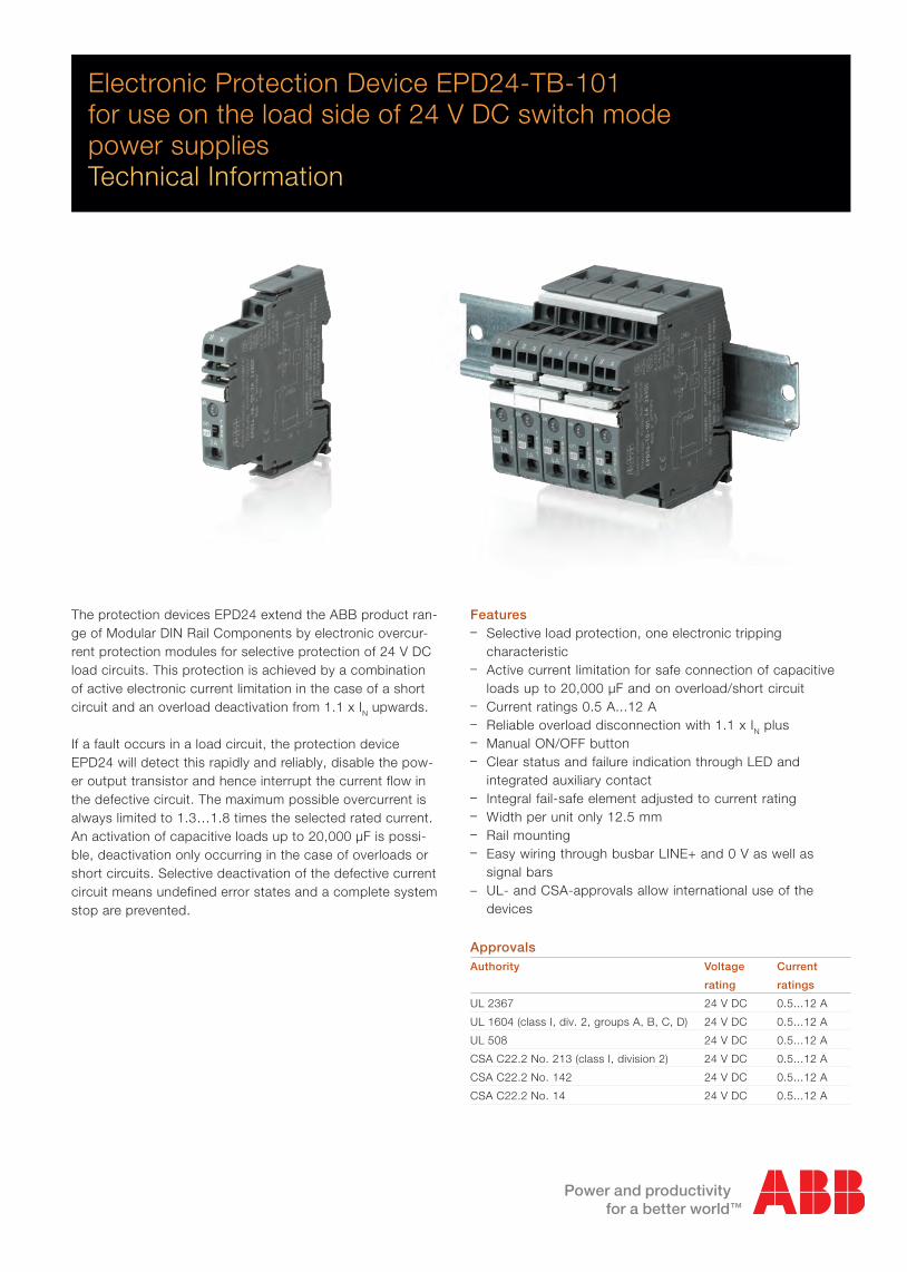
The protection devices EPD24 extend the ABB product ran-ge of Modular DIN Rail Components by electronic overcur-rent protection modules for selective protection of 24 V DC load circuits. This protection is achieved by a combination of active electronic current limitation in the case of a short circuit and an overload deactivation from 1.1 x IN upwards.
If a fault occurs in a load circuit, the protection device EPD24 will detect this rapidly and reliably, disable the pow-er output transistor and hence interrupt the current flow in the defective circuit. The maximum possible overcurrent is always limited to 1.3…1.8 times the selected rated current. An activation of capacitive loads up to 20,000 μF is possi-ble, deactivation only occurring in the case of overloads or short circuits. Selective deactivation of the defective current circuit means undefined error states and a complete system stop are prevented.
Approvals Authority Voltage Current
rating ratings
UL 2367 24 V DC 0.5...12 A
UL 1604 (class I, div. 2, groups A, B, C, D) 24 V DC 0.5...12 A
UL 508 24 V DC 0.5...12 A
CSA C22.2 No. 213 (class I, division 2) 24 V DC 0.5...12 A
CSA C22.2 No. 142 24 V DC 0.5...12 A
CSA C22.2 No. 14 24 V DC 0.5...12 A
Features– Selective load protection, one electronic tripping characteristic– Active current limitation for safe connection of capacitive loads up to 20,000 µF and on overload/short circuit– Current ratings 0.5 A...12 A– Reliable overload disconnection with 1.1 x IN plus – Manual ON/OFF button – Clear status and failure indication through LED and integrated auxiliary contact– Integral fail-safe element adjusted to current rating– Width per unit only 12.5 mm– Rail mounting– Easy wiring through busbar LINE+ and 0 V as well as signal bars – UL- and CSA-approvals allow international use of the devices

2 2CDC444002D0201
Operating data
Operating voltage UB 24 V DC (18...32 V DC)
Current rating IN fixed current ratings:
0.5, 1, 2, 3, 4, 6, 8, 10, 12 A
Closed current I0 ON condition: typically 20...30 mA
depending on signal output
Staus indication – multicolour LED:
by means of Green: – unit is ON
– load circuit / Power-MOSFET
is switched on
Orange: – in the event of overload or
short circuit until electronic
disconnection
Red: – unit electronically disconnected
– load circuit/Power-MOSFET OFF
– undervoltage (UB < 8 V)
– after switch-on till the end
of the delay period
OFF: – manually switched off
or device is dead
– potential-free auxiliary contact
– ON/OFF condition of switch
Load circuit
Load output Power-MOSFET switching output
(high slide switch)
Overload disconnection typically 1.1 x IN (1.05...1.35 x IN)
Short-circuit current IK active current limitation (see table 1)
Trip time see time/current characteristics
For electronic typically 3 s at Iload > 1.1 x IN
disconnection typically 100 ms...3 s at Iload > 1.8 x IN
(or 1.5 x IN/1.3 x IN)
Temperature disconnection internal temperature monitoring with
electronic disconnection
Low voltage monitoring with hysteresis, no reset required:
load output load »OFF« at US< 8 V
Starting delay tStart typically 0.5 sec
after every switch-on and
after applying UB
Disconnection of electronic disconnection upon overload/
load circuit short-circuit
Free-wheeling circuit suitable external free-wheeling circuit to be
used with inductive load
Several load outputs must not be connected in parallel
Technical dataAmbient temperature 25 °C, Operating voltage 24 V DC
Signal output
Electrical data potential-free auxiliary contact
max. 30 V DC/0.5 A, min. 10 V DC/10 mA
ON condition LED green voltage UB applied, switch is in ON position
and no overload, no short circuit
OFF condition LED off – device switched off
(switch is in OFF position)
– no voltage UB applied
Fault condition LED orange overload condition > 1.1 x IN up to
electronic disconnection
Fault condition LED red – electronic disconnection upon
overload or short circuit
– device switched off with control signal
(switch is ON)
Auxiliary contact single signal, make contact
contact open, terminal 13-14
Fault signal output fault conditions
– no operating voltage UB
– ON/OFF switch is in OFF position
– red LED lighted (electronic disconnection)
www.e-t-a.com
Elektronischer Sicherungsautomat ESX10-TInstallations- und Sicherheitshinweise
08/09(200110) 5 - 47
5
LINE+ 1
LOAD+2
0V 3
ESX10-TA-100Ohne Signaleingang/-Ausgang
LINE+ 1
SF 23
IN 21
2 LOAD+
0V 3
ESX10-TB-114Mit Steuereingang IN+(+DC 24 V)Mit Statusausgang SF(+24 V = Lastausgang EIN)
Normalzustand: SF +24 V = OKFehlerzustand: SF 0 V
LINE+ 1
SF 23
RE 22
2 LOAD+
0V 3
ESX10-TB-124Mit Reseteingang RE(+DC 24 V ↓)Mit Statusausgang SF(+24 V = Lastausgang EIN)
Normalzustand: SF +24 V = OKFehlerzustand: SF 0 V
LINE+ 1
14
13
2 LOAD+
0V 3
ESX10-TB-101Ohne SignaleingangMit Meldeausgang F(Einzelsignal, Schließer)
Normalzustand: 13-14 geschlossenFehlerzustand: 13-14 geöffnet
LINE+ 1
12
11
2 LOAD+
0V 3
ESX10-TB-102Ohne SignaleingangMit Meldeausgang F(Einzelsignal, Öffner)
Normalzustand: 11-12 geöffnetFehlerzustand: 11-12 geschlossen
LINE+ 1
SF 23
RE 22
2 LOAD+
0V 3
ESX10-TB-127Mit Reseteingang RE(+DC 24 V ↓)Mit Statusausgang SF invertiert(0 V = Lastausgang EIN)
Normalzustand: SF 0 V = OKFehlerzustand: SF +24 V
ESX10-T Signaleingänge / -ausgänge (Anschlussdiagramme)Die Signalkontakte werden im Aus- oder Fehlerzustand gezeigt
ESX10-T Signaleingänge/-ausgänge (Anschlussdiagramme)
Operating condition: 13-14 closed
Fault condition: 13-14 open
Table 1
Voltage drop, current limitation, max. load current
Current Typically Active current Max. load 100 %
rating voltage drop limitation current at ON duty
IN UON at IN (typically) Tamb = 40 °C Tamb = 50 °C
0.5 A 70 mV 1.8 x IN 0.5 A 0.5 A
1 A 80 mV 1.8 x IN 1 A 1 A
2 A 130 mV 1.8 x IN 2 A 2 A
3 A 80 mV 1.8 x IN 3 A 3 A
4 A 100 mV 1.8 x IN 4 A 4 A
6 A 130 mV 1.8 x IN 6 A 5 A
8 A 120 mV 1.5 x IN 8 A 7 A
10 A 150 mV 1.5 x IN 10 A 9 A
12 A 180 mV 1.3 x IN 12 A 10.8 A
Wiring diagramm
EPD24-TB-101 Without signal input With signal output (Single signal, N/O)
Attention: when mounted side-by-side without convection the EPD24 should not carry more than 80 % of its rated load with 100 % ON duty due to thermal effects.

2CDC444002D0201 3
General data
Fail-Safe element backup fuse for EPD24 not required
because of the integral redundant fail-safe
element
Housing material moulded
Mounting symmetrical rail acc. to EN 50022-35x7.5
Ambient temperature 0...+50 °C (without condensation,
see EN 60204-1)
Storage temperature -20...+70 °C
Humidity 96 hrs/95 % RH/40 °C acc. to
IEC 60068-2-78, test cab.
climate class 3K3 acc. to EN 60721
Vibration 3 g, test acc. to IEC 60068-2-6 test Fc
Degree of protection housing: IP20 acc. to EN 60529
terminals: IP20 acc. to EN 60529
EMC emission: EN 61000-6-3
(EMC directive, CE logo) susceptibility: EN 61000-6-2
Isolations coordination 0.5 kV/pollution degree 2
(IEC 60934) reinforced insulation in operating area
Dielectric strength max. 32 V DC (load circuit)
Isolation resistance n/a, only electronic disconnection
(OFF condition)
Approvals/ UL 2367, File # E 339236,
Declarations of Solid State Overcurrent Protectors
conformity UL 1604, File # E 339238 (class I, division 2,
groups A, B, C, D)
UL 508, File # E 149922
CSA C22.2 No. 213 (class I, division 2),
CSA C22.2 No. 142,
CSA C22.2 No. 14, File # 2305929
CE logo
Dimensions (W x H x L) 12.5 x 80 x 83 mm
Weight approx. 65 g
Terminals LINE+ / LOAD+ / 0V
Screw terminals M4
Max. cable cross section
Flexible with wire end ferrule w/wo plastic sleeve 0.5 ... 10 mm2
Multi-lead connection (2 identical cables)
rigid/flexible 0.5 ... 4 mm2
Flexible with wire end ferrule without plastic sleeve 0.5 ... 2.5 mm2
Flexible with TWIN wire end ferrule with plastic sleeve 0.5 ... 6 mm2
Wire stripping length 10 mm
Tightening torque (EN 60934) 1.5 ... 1.8 Nm
Terminals auxiliary contacts
Screw terminals M3
Max. cable cross section
Flexible with wire end ferrule w/wo plastic sleeve 0.25 ... 2.5 mm2
Wire stripping length 8 mm
Tightening torque (EN 60934) 0.5 Nm
Please noteThe user must ensure that the cable cross sections of the relevant load circuit are suitable for the current rating of the EPD24 used.
Automatic start-up of machinery after shut down must be prevented (Machinery Directive 98/37/EG and EN 60204-1). In the event of a short circuit or overload the load circuit will be disconnected electronically by the ESPD24.
Type codeEPD Electronic Protection Device, with current limitation
Operating voltage
24 operating voltage 24 V DC
Mounting and design
TB rail mounting, with auxiliary contact and slot
for signal bars
Version
1 without physical isolation in the event of a failure
Signal input
0 without signal input
Signal output
1 auxiliary contact N/O
Current rating
xxA current rating in A
EPD 24 - TB - 1 0 1 xxA
Dimensions

4 2CDC444002D0201
disconnection typically 1.1 x IN
current limitationtypically 1.8 x IN
I
10000
1000
1 2 4
trip
tim
e in
sec
onds
...times rated current
100
10
1
0.1
0.01
3 50
1.8 x IN1)
5
K
1)
Reliable trippingCharacteristic curve and wire lengthsTime/Current characteristic curve (Tambient = 25 °C)– The trip time is typically 3 s in the range between 1.1 and
1.8 x IN1).
– Electronic current limitation occurs at typically 1.8 x IN1)
which means that under all overload conditions (independent of the power supply and the resistance of the load circuit) the max. overload before disconnection will not exceed 1.8 x IN
1) times the current rating. Trip time is between 100 ms and 3 s (depending on overload or at short circuit).
– Without this current limitation a considerably higher over-load current would flow in the event of an overload or short circuit.
1) Current limitation typically 1.8 x IN at IN = 0.5 A...6 A Current limitation typically 1.5 x IN at IN = 8 A or 10 A Current limitation typically 1.3 x IN at IN = 12 A
Selection table for the incoming cable lengths with different cable cross sections
Cable cross section A (mm2) 0.14 0.25 0.34 0.5 0.75 1.00 1.50
Cable length L (m) (= single length) overall cable resistance RL (Ω) 3)
5 1.27 0.71 0.52 0.36 0.24 0.18 0.12
10 2.54 1.42 1.05 0.71 0.47 0.36 0.24
15 3.81 2.14 1.57 1.07 0.71 0.53 0.36
20 5.09 2.85 2.09 1.42 0.95 0.71 0.47
25 6.36 3.56 2.62 1.78 1.19 0.89 0.59
30 7.63 4.27 3.14 2.14 1.42 1.07 0.71
35 8.90 4.98 3.66 2.49 1.66 1.25 0.83
40 10.17 5.70 4.19 2.85 1.90 1.42 0.95
45 11.44 6.41 4.71 3.20 2.14 1.60 1.07
50 12.71 7.12 5.24 3.56 2.37 1.78 1.19
75 19.07 10.68 7.85 5.34 3.56 2.67 1.78
100 25.34 14.24 10.47 7.12 4.75 3.56 2.37
125 31.79 17.80 13.09 8.90 5.93 4.45 2.97
150 38.14 21.36 15.71 10.68 7.12 5.34 3.56
175 44.50 24.92 18.32 12.46 8.31 6.23 4.15
200 50.86 28.48 20.94 14.24 9.49 7.12 4.75
225 57.21 32.04 23.56 16.02 10.68 8.01 5.34
250 63.57 35.60 26.18 17.80 11.87 8.90 5.93 3) RL = (ρ0 x 2 x L) / A (Ω), resistivity of copper ρ0 = 0,0178 (Ω mm2)/m
Example 1: max. length for 1.5 mm2 and 3 A: 214 m Example 2: max. length for 1.5 mm2 and 6 A: 106 m Example 3: mixed wiring (control cabinet --- sensor/actuator level) R1 = 40 m for 1.5 mm2 und R2 = 5 m for 0.25 mm2: R1 = 0.95 Ω, R2 = 0.71 Ω, total (R1 + R2) = 1.66 Ω
Maximum cable lengthsEPD24 reliably trips from 0 Ω to max. circuitry resistance Rmax.
Calculation of Rmax Selected current rating IN (A) 3 6
Operating voltage US (V DC) 2) 19.2 19.2
(= 80 % of 24 V)
Trip current Ioff = 1,25 x IN (A) 3.75 7.50
(EPD24 trips after 3 s)
Rmax = (US/Ioff) -0.050 (Ω) 5.07 2.51
2) Voltage drop of EPD24 and tolerance of trip point (typically 1.1 x IN = 1.05 ... 1.35 x IN) have been taken into account

2CDC444002D0201 5
Installation and safety instructions UL approvals/CSA approvals UL1604 UL File # E 339238
CSA C22.2 No. 213 (Class I, Division 2) CSA File # 2305929
Operating Temperature Code T5 – This equipment is suitable for use in Class I, Division 2, Groups A, B, C and D or non-hazardous locations only
WARNING: – Exposure to some chemicals may degrade the sealing properties of materials used in the following device: relay Sealant Material: Generic Name: Modified diglycidyl ether of bisphenol A Supplier: Fine Polymers Corporation Type: Epi Fine 4616L-160PK Casing Material: Generic Name: Liquid Crystal Polymer Supplier: Sumitomo Chemical Type: E4008, E4009, or E6008
RECOMMENDATION: – Periodically inspect the device named above for any degradation of properties and replace if degradation is found
WARNING – EXPLOSION HAZARD: – Do not disconnect equipment unless power has been removed or the area is known to be non-hazardous – Substitution of any components may impair suitability for Class I, Division 2
This device is OPEN type equipment that must be used within a suitable end-use system enclosure
UL2367 Non-hazardous use - UL File # E 339236
UL 508 Non-hazardous use - UL File # E 149922
CSA C22.2 No. 14 CSA C22.2 No. 142 - CSA File # 2305929
Instruction leaflet
UL1604 - File # E 339238 C22.2 No.213 - File # 2305929This device is suitable for use in Class I, Div 2, Groups A, B, C, D;TC T5; Hazardous locations or nonhazardous locations only
Warnings:1. Remove power before disconnecting device or the area is known to be nonhazardous2. Components substitutions may impair suitability of Class I, Div 2.3. Chemical exposure may degrade internal relay’s sealing property. Refer to data sheet/installation guidlines for installation and safety instructions.
UL2367 - File # E 339236Non-hazardous use
Refer to data sheet/installation guidelines for installation and safety instructions.
UL508 - File # E 149922 C22.2 No.14 - File # 2305929Non-hazardous use Non-hazardous use
Refer to data sheet/installation guidelines for installation and safety instructions.
This device is suitable for use in Class I, Div 2, Groups A, B, C, D; TC T5; Hazardous locations or nonhazardous locations only
Warnings:1. Remove power before disconnecting device or the area is known to be nonhazardous2. Components substitutions may impair suitability of Class I , Div 2.3. Chemical exposure may degrade internal relay's sealing property.
Electronic Protection DeviceEPD24-T
UL2367
UL1604
Non-hazardous use UL File # xxx
Refer to data sheet / installation guidelines for installation and safety instructions.
ABB STOTZ-KONTAKT GmbHD-69123 Heidelberg . Eppelheimer Str. 82Tel.: +49 6221 701-0 . Fax: +49 6221 701-1325E-Mail: [email protected]://www.abb.de/stotzkontakt
cUL508
Non-hazardous use UL File # xxx
C22.2 No. 213
UL File # xxx CSA File # xxx
ABB STOTZ-KONTAKT GmbHD-69123 Heidelberg · Eppelheimer Str. 82Tel.: +49 6221 701-0 · Fax: +49 6221 701-1325E-Mail: [email protected]://www.abb.de/stotzkontakt

6 2CDC444002D0201
Power distribution system and accessory assembling
Mounting procedureBefore wiring insert busbars into protector block. Max. 10 insertion/removal cycles for busbars.
RecommendationAfter 10 units the busbars should be interrupted and receive a new entry live.
Table of lengths for busbars(Order code 2CDE605100R0500)
No. of units 2 3 4 5 6 7 8 9 10
Length of busbar 22 34.5 47 59.5 72 84.5 97 109.5 122
(mm) ± 0.5 mm
Connection diagram and application example 1)
Group signalisation (series connection)
The EPD24 features an integral power distribution system. The following wiring modes are possible with the pluggable busbars and signal bars:
– LINE+ (24 V DC)– 0 V Caution: The EPD24 require a 0 V connection– Auxiliary contacts
3 0V 3 0V 3 0V
+ line entry+ line entry for the SI
- line entry
power supplyDC 24 V
LINE + busbar(X 222 611 02 respectivelyX 222 611 34)
group signallingby means of an signal lamp
jumpers (X 222 005 13)are staggered
0 V busbar(X 222 611 02 respectivelyX 222 611 34)
+24V
0V
load load load
+ ++- - -
13
1LINE+
14
ESX10-TB-101
2 LOAD+
13
1LINE+
14 13
1LINE+
14
ESX10-TB-101
2 LOAD+
ESX10-TB-101
2 LOAD+
12.5 x n = width of protector blocke. g. 12.5 x 5 = 62.5insert busbars
and protection slidesto be flush with housing sides
insert signalbars to be flush withhousing and place themcentrally over the contacts
LINE+ busbar2CDE605100R0500
0 V busbar2CDE605100R0500
signal bar2CDE605200R0021
remove protection againstbrush contact from bottom side
(12.5 x n)-3 = length of busbars ± 0.5e. g. (12.5 x 5)-3 = 59.5 ± 0.5
insert protection againstbrush contact
continuous busbar500 mm length, cut
+ line entry for the auxiliary contact
1) Auxiliary contacts are shown in the OFF or fault condition.
LINE + busbar
group signallingby means of an signal lamp
signal bars are staggered
0 V busbar
EPD24EPD24EPD24
power supply24 V DC

2CDC444002D0201 7
Order details
Electronic protection devices Rated current IN Type code Order code bbn 40 16779 Weight Packing-
A EAN 1 piece in kg unit
0.5 EPD24-TB-101-0.5A 2CDE601101R2905 829960 0.065 4
1 EPD24-TB-101-1A 2CDE601101R2001 829984 0.065 4
2 EPD24-TB-101-2A 2CDE601101R2002 830003 0.065 4
3 EPD24-TB-101-3A 2CDE601101R2003 830027 0.065 4
4 EPD24-TB-101-4A 2CDE601101R2004 830041 0.065 4
6 EPD24-TB-101-6A 2CDE601101R2006 830065 0.065 4
8 EPD24-TB-101-8A 2CDE601101R2008 830089 0.065 4
10 EPD24-TB-101-10A 2CDE601101R2010 830102 0.065 4
12 EPD24-TB-101-12A 2CDE601101R2012 830126 0.065 4
Accessories Type code Order code bbn 40 16779 Weight Packing
EAN 1 piece in kg unit
Busbars
for LINE+ and 0 V,
grey insulation, length 500 mm1) EPD-BB500 2CDE605100R0500 830140 0.20 10
Signal bars
for auxiliary contacts,
grey insulation, length 21 mm EPD-SB21 2CDE605200R0021 830164 0.04 10
1) Ampacity at one line entry Imax = 50 A (Recommendation: mid line entry)
Ampacity at two line entries Imax = 63 A

Note:We reserve the right to make technical changes or modify the contents of this document without prior notice. With regard to purchase orders, the agreed particulars shall prevail. ABB AG does not accept any responsibility whatsoever for potential errors or possible lack of information in this document.
We reserve all rights in this document and in the subject matter and illustrations contained therein. Any reproduction, disclosure to third parties or utilization of its contents - in whole or in parts - is forbidden without prior written consent of ABB AG.
Copyright© 2011 ABBAll rights reserved
Ord
er n
umbe
r 2C
DC
4440
02D
0201
prin
ted
in G
erm
any
(02/
11-4
-ZV
D)ABB STOTZ-KONTAKT GmbH
Postfach 10 16 80 69006 Heidelberg, GermanyPhone: +49 6221 701 0 Telefax: +49 6221 701 1325 E-Mail: [email protected]
www.abb.de/stotzkontakt
Contact us