Electronic Product Catalog - Atlantic ValveWIKA transmitters and transducers are designed for long...
200
Electronic Product Catalog Pressure Transmitters and Transducers Electronic Product Catalog R ■ General Purpose Pressure Transmitters ■ Hazardous Area Pressure Transmitters ■ Submersible Liquid Level Transmitters ■ Special Purpose Pressure Transmitters ■ Meters and Displays ■ 3A Sanitary Transmitters
Transcript of Electronic Product Catalog - Atlantic ValveWIKA transmitters and transducers are designed for long...

Electronic Product Catalog Pressure Transmitters and Transducers
ElectronicProduct Catalog
R
General Purpose Pressure Transmitters Hazardous Area Pressure Transmitters Submersible Liquid Level Transmitters Special Purpose Pressure Transmitters Meters and Displays 3A Sanitary Transmitters

WIKA Electronic Product CatalogGeneral Purpose Pressure TransmittersHazardous Area Pressure TransmittersSubmersible Liquid Level TransmittersSpecial Purpose Pressure TransmittersMeters and Displays3A Sanitary TransmittersEffective January 2013, Rev. March 2013
Hastelloy® is a registered trademark of the Cabot family of companies. Viton® & Teflon® are registered trademarks of the E.I. DuPont family of companies.UniTrans® is a registered trademark owned by Consolidated, Inc.NEOBEE® is a registered trademark of the Stepan Company.Cherry Burrell® is a registered trademark of Waukesha Cherry-Burrell.Neoprene® is a registered trademark of E.I. du Pont de Nemours and Company.
© Copyright WIKA Instrument, LP, Lawrenceville, GA 30043 All rights reserved
Printed in the United States of America
is a registered trademark of WIKA Instrument, LP, Lawrenceville, GA
Electronic Product Catalog
Electronic PressureMeasurement
R
1
TABLE OF CONTENTS
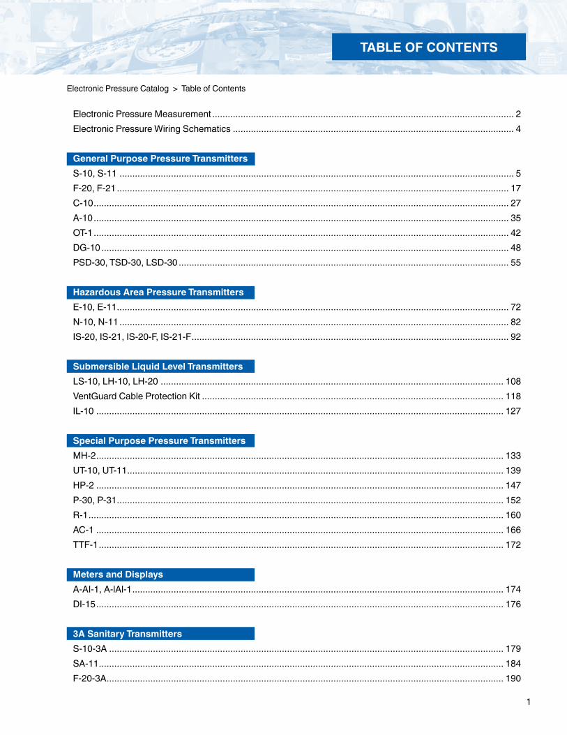
Electronic Pressure Catalog > Table of Contents
Electronic Pressure Measurement ..................................................................................................................... 2Electronic Pressure Wiring Schematics ............................................................................................................. 4
General Purpose Pressure Transmitters S-10, S-11 ......................................................................................................................................................... 5F-20, F-21 ........................................................................................................................................................ 17C-10 ................................................................................................................................................................. 27A-10 ................................................................................................................................................................. 35 OT-1 ................................................................................................................................................................. 42DG-10 .............................................................................................................................................................. 48PSD-30, TSD-30, LSD-30 ................................................................................................................................ 55 Hazardous Area Pressure TransmittersE-10, E-11 ........................................................................................................................................................ 72N-10, N-11 ....................................................................................................................................................... 82IS-20, IS-21, IS-20-F, IS-21-F ........................................................................................................................... 92
Submersible Liquid Level TransmittersLS-10, LH-10, LH-20 ..................................................................................................................................... 108VentGuard Cable Protection Kit ..................................................................................................................... 118 IL-10 .............................................................................................................................................................. 127
Special Purpose Pressure TransmittersMH-2 .............................................................................................................................................................. 133 UT-10, UT-11 .................................................................................................................................................. 139HP-2 .............................................................................................................................................................. 147P-30, P-31 ...................................................................................................................................................... 152R-1 ................................................................................................................................................................. 160AC-1 .............................................................................................................................................................. 166TTF-1 ............................................................................................................................................................. 172
Meters and DisplaysA-AI-1, A-lAl-1 ................................................................................................................................................ 174DI-15 .............................................................................................................................................................. 176
3A Sanitary TransmittersS-10-3A ......................................................................................................................................................... 179SA-11 ............................................................................................................................................................. 184F-20-3A .......................................................................................................................................................... 190

2
ELECTRONIC PRESSURE MEASUREMENT
Electronic Pressure Catalog > Electronic Pressure Measurement
Electronic Pressure Measurement
Because the transmitter output is linear, it will directly relate to the applied pressure. At 25 psi the output will be 8 mA, at 50 psi, 12 mA and at 75 psi, 16 mA. If the device reading this mA signal is a programmable panel meter, it can convert the 4-20 mA signal to 0-100 psi and display the pressure on the digital readout. Since the 4-20 mA is consistent, the meter can be programmed to display any engineering units desired. If a bar reading is required, the meter is programmed to display 0 bar at 4 mA and 6.89 bar at 20 mA. The meter circuitry completes all other calculations automatically.
All WIKA electronic pressure transmitters and transducers convert an applied pressure into an electrical signal. This signal is sent to computers, PLC's (programmable logic controllers), chart recorders, digital panel meters or other devices that interpret this electrical signal and use it to display, record and/or change the pressure in the system being monitored.
The most popular signal used in industrial applications is a 4-20 milliamp (mA) 2-wire current loop. Other signals used include 1-5 volts, 0-5 volts, 0.5-4.5 volts, 0-10 volts (3 wire systems) and 0-100 millivolts (4 wire systems).In many cases the display device that the transmitter is connected to can accept more than one type of output - for example, 4-20 mA or 0-5 volts. Because of its popularity, WIKA stocks a large inventory of 4-20 mA output transmitters in many different models.
A pressure transmitter converts an unamplified signal such as 2mV/V into an amplified signal like 4-20mA or 0-10V. A pressure transducer converts applied pressure to an unamplified signal such as 2mV/V. Many users refer to transmitters and transducers interchangeably. This can create some confusion, but it may be helpful to note that general purpose pressure sensors are most commonly referred to as pressure transducers.
LinearityWhat makes these devices useful is that the output is directly proportional to the applied pressure. WIKA transmitters are described in part by pressure range and output type. For example, a transmitter with a 0-100 psi range and 4-20 mA output would produce a 4 mA output at 0 pressure and 20 mA at 100 psi.
100 psi
0 psi4 mA 20 mA8mA 12mA 16mA
75 psi
50 psi
25 psi
Increasing Pressure
IncreasingOutput
The straight line shown above represents an ideal, perfectly linear output. In reality, errors are introduced into the output signal by the various transmitter components. The amount of error introduced refers to the deviation from the ideal straight line.
Accuracy
20 mA
Increasing Output
100 psi
4 mA0 psi
IdealLinearity
Calibration Curve (overstated for clarity)
Increasing Pressure

3
ELECTRONIC PRESSURE MEASUREMENT
PerformanceWIKA transmitters and transducers are designed for long term, reliable performance in difficult industrial environments. Most models feature stainless steel construction, moisture and vibration protected circuitry, and all are calibrated and tested prior to shipment. A variety of options are available on most models to meet specific needs.
ApplicationsWIKA transmitters are available in many different models that have features to meet the needs of specificapplications. Model types are described below:Standard industrial grade transmitters - general purpose 0.25% accuracy transmitters for many industrial applications such as hydraulics and pneumatics.
Flush diaphragm transmitters - feature a non-clogging, flat diaphragm for use when the media is of high viscosity or contains particulates that might plug the 1/8" orifice found on the standard industrial (NPT) series.
Intrinsically safe transmitters - used in environments containing explosive or flammable gases or liquids. These instruments are designed so they cannot generate enough heat or spark to ignite flammable media or flammable gases in the environment. They require the use of intrinsi-cally safe barriers and provide protection similar to explosion-proof devices without requiring containment in an explosion-proof housing.Approved for Class I Division 1 hazardous locations.
NEMA 4X transmitters with field case- designed for extremely dirty or corrosive environments, they feature washdown and corrosion resistance.
OEM transmitters - 0.5% accuracy class instruments without adjustable zero and span for general purpose pressure measurement applica-tions. They feature excellent repeatability and vibration resistance.
A-10 - Low cost, high level output for general purpose pressure measurement applications.
OEM sensors - provide a "low level" millivolt-per-volt output for OEM design engineers who want to build their own power supply and signal conditioning circuitry.
Submersible liquid level transmitters - measure the static pressure of liquid above the diaphragm and are used in many liquid level monitoring and control applications.
3A Sanitary transmitters - feature a Tri-Clamp® quick release connection with flush diaphragm for use in food and pharmaceutical pressure measurement applications. The connection is designed to prevent product buildup and reduce the possibility of bacterial contamination of the product.
High precision digital transmitters - for laboratory or industrial applications where 0.1% or 0.05% accuracy is required along with durable, industrial grade construction.
UniTrans® universal pressure transmitter - features user programmability and LCD display.
Local indicating transmitters - feature a 4" gauge and a transmitter for local and remote pressure indication.
Low/differential pressure transmitters - measure clean, dry, inert gaseous media from 0.2 inches water column to 15 psi.
E-10 explosion-proof transmitters - approved for Class I Division 1 hazardous locations.
N-10 non-incendive transmitters - approved for Class I Division 2 hazardous locations.
Digital panel meters & controllers -user programmable to display pressure in any desired engineering units. They are available with a variety of options including dual programmable relays for alarm or control applications.
Contact WIKA for additional information and product support for specific applications.
"Accuracy" most commonly refers to the percent deviation from the ideal. It can also be calculated using linearity, hysteresis and repeatability values. Most WIKA transmitters have less than a 0.25% linearity deviation over the span. See the specifications section for each model number for detailed information. In industrial applications, repeatability is usually more important than "full scale accuracy" matching a traceable standard. WIKA transmitters feature excellent repeatability - less than 0.05% span for most models.
When comparing accuracy, note there are many different ways manufacturers calculate accuracy. Be sure to consider temperature compensation, as industrial environments rarely match the laboratory conditions sometimes used by other transmitter manufacturers when determining accuracy.
Electronic Pressure Catalog > Electronic Pressure Measurement
Electronic Pressure Measurement
4
TRONIC WIRING SCHEMATICS
Electronic Pressure Catalog > Electronic Pressure Measurement
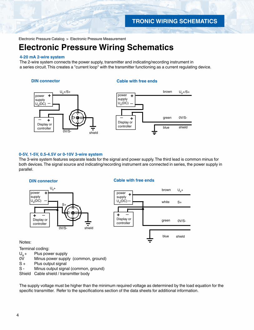
Electronic Pressure Wiring Schematics
The supply voltage must be higher than the minimum required voltage as determined by the load equation for the specific transmitter. Refer to the specifications section of the data sheets for additional information.
Notes:Terminal coding:UB + Plus power supply0V Minus power supply (common, ground)S + Plus output signalS - Minus output signal (common, ground)Shield Cable shield / transmitter body
+
Display orcontroller
+ _
_
0V/S-
brown
green
white S+
UB+power supplyUB(DC)
shieldblue
Cable with free ends
13
2
+_
Display orcontroller
+ _
0V/S-
UB+
S+
shield
DIN connector
0-5V, 1-5V, 0.5-4.5V or 0-10V 3-wire systemThe 3-wire system features separate leads for the signal and power supply. The third lead is common minus for both devices. The signal source and indicating/recording instrument are connected in series, the power supply in parallel.
power supplyUB(DC)
31
2
+_
+Display orcontroller
_
0V/S-
UB+/S+
shield
+_
_ +
UB+/S+
blue
green 0V/S-
shield
brownpower supplyUB(DC)
Display orcontroller
Cable with free endsDIN connector
4-20 mA 2-wire systemThe 2-wire system connects the power supply, transmitter and indicating/recording instrument ina series circuit. This creates a "current loop" with the transmitter functioning as a current regulating device.
power supplyUB(DC)

5
GEN
ERAL PURPO
SE
GENERAL PURPOSE
Electronic Pressure Catalog > General Purpose > S-10, S-11
Type S-10, S-11 General Purpose Pressure Transmitters
WIKA S-10 and S-11 pressure transmitters are precision engineered to fit most industrial pressure measurement applications. The compact, rugged design makes these instruments suitable for applications including hydraulics and pneumatics, vacuum, test equipment, liquid level measurement, press control, compressor control, pump protection and numerous other processing and control operations. A wide range of electrical connection and process connection options are available to meet almost any requirement.
Rugged constructionThe S-10 features an all-welded stainless steel measuring cell for improved media compatibility. There are no internal soft sealing materials that may react with the media or deteriorate over time. The compact case is also made of stainless steel and is available with environmental protection ratings up to NEMA 6P / IP 68.
The S-11 transmitter features a flush diaphragm process connection. The S-11 is specifically designed for the measurement of viscous fluids or media containing solids that may clog a NPT process connection. Flush diaphragm pressure transmitters are available in pressure ranges from 50 InWC to 8,000 psi. For high temperature media, an integral cooling element is available on the S-11. This option increases the maximum media temperature to 302 OF.
Each instrument undergoes extensive quality control testing and calibration to achieve an accuracy of < 0.25% full scale. The printed circuit boards use state-of-the-art surface mount technology and are potted in silicone gel for protection against mechanical shock, vibration and moisture. Each is individually temperature compensated to assure accuracy and long-term stability even when exposed to severe ambi-ent temperature variations.
Left: S-10 with NPT process connectionCenter: S-11 with flush diaphragm process connectionRight: S-11 with flush diaphragm process connection and integral cooling element
Applications
Hydraulics and pneumatics Test equipment Pump and compressor control Liquid level measurement
Special Features
Standard ranges available from stock 4-20 mA 2-wire output signal, others available Highly resistant to pressure spikes and vibration Stainless steel case and wetted parts Can be assembled to diaphragm seals for special applications
Description
For full specifications, visit www.wika.com to download datasheets S-10, S-11 or call 1-800-381-6549

6
GEN
ERAL
PU
RPO
SE
GENERAL PURPOSE
Specifications Type S-10, S-11
Pressure range 50 InWC 5 psi 10 psi 25 psi 30 psi 60 psi 100 psi 160 psi 200 psiMaximum pressure* 14 psi 29 psi 58 psi 145 psi 145 psi 240 psi 500 psi 1,160 psi 1,160 psiBurst pressure** 29 psi 35 psi 69 psi 170 psi 170 psi 290 psi 600 psi 1,390 psi 1,390 psiPressure range 300 psi 500 psi 1,000 psi 2,000 psi 3,000 psi 5,000 psi 8,000 psi 10,000 psi1 15,000 psi1Maximum pressure* 1,160 psi 1,160 psi 1,740 psi 4,600 psi 7,200 psi 11,600 psi 17,400 psi 17,400 psi 21,750 psiBurst pressure** 1,390 psi 5,800 psi 7,970 psi 14,500 psi 17,400 psi 24,650 psi 34,800 psi 34,800 psi 43,500 psivacuum, gauge pressure, compound ranges, and absolute pressure references are available1) Ranges only available with Model S-102) For Model S-11 the burst pressure is limited to 21,000psi unless the pressure seal is accomplished by using the sealing ring underneath the hex.*Pressure applied up to the maximum rating will cause no permanent change in specifications but may lead to zero and span shifts**Exceeding the burst pressure may result in destruction of the transmitter and possible loss of mediaMaterials Wetted parts (other materials see WIKA diaphragm seal program) Type S-10 Stainless steel Type S-11 Stainless steel
O-ring: NBR 3) Viton® or EPDM Case Stainless steelInternal transmission fluid 4) Synthetic oil Halocarbon® oil for oxygen applications 5)
Listed by FDA for food applications 3) O-ring made of Viton® or EPDM for type S-11 with integral cooling element. 4) Not available with type S-10 in pressure ranges >300 psi. 5) Media temperature for oxygen version: -4 ... +140 °F (-20....+60°C). Oxygen version is not available in vacuum and absolute pressure ranges or with S-11 > 500 psi
Power supply UB 6) UB in DC V 10 < UB ≤ 30 (14 ... 30 with signal output 0 ... 10 V)
Signal output and RA in Ohm 4 ... 20 mA, 2-wire RA < (UB - 10 V) / 0.02 A maximum load RA 0 ... 20 mA, 3-wire RA < (UB - 3 V) / 0.02 A
0 ... 5 V, 3-wire RA > 5000 0 ... 10 V, 3-wire RA > 10,000 other signal outputs available
Adjustability zero/span % ± 5 using potentiometers inside the instrumentResponse time (10 ... 90 %) ms < 1 (< 10 ms at media temperatures below –22°F (-30°C) for ranges < 300 psi
or with flush diaphragm process connection)Isolation voltage DC V 500
6) NEC Class 02 power supply (low voltage and low current max. 100 VA even under fault conditions)Accuracy 7) % of span ≤ 0.25 0.125 8) (BFSL)
% of span ≤ 0.5 0.25 8) (limit point calibration) 7) Including linearity, hysteresis and repeatability. Limit point calibration performed in vertical mounting position with pressure connection facing down.8) Improved accuracy is available for pressure ranges > 100 InWC
Non-repeatability % of span ≤ 0.11-year stability % of span ≤ 0.2 (at reference conditions)Permissible temperature of Medium 9) -22 ... +212 °F -40 ... +257 °F -30 ... +100 °C -40 ... +125 °C S-11 with cooling element: -4 ... +302 °F S-11 with cooling element: -20 ... +150 °C Ambient 9) -4 ... +176 °F -20 ... +80 °C
S-11 with cooling element: -4 ... +176 °F S-11 with cooling element: -20 ... +80 °C Storage 9) -40 ... +212 °F -40 ... +100 °C
S-11 with cooling element: -4 ... +212°F S-11 with cooling element: -20 ... +100 °C9) Also complies with EN 50178, Tab. 7, Type C, Class 4KH Operation, 1K4 Storage, 1K3 Transport
Compensated temperature range 32 ... +176 °F 0 ... +80 °CTemperature coefficients (TC) withincompensated temp range: Mean TC of zero % of span ≤ 0.2 / 10 K (< 0.4 for pressure range < 100 InWC) Mean TC of range % of span ≤ 0.2 / 10 KCE - conformity Pressure equipment directive 97/23/EC EMC directive 2004/108/EEC, EN 61 326 Emission Group (Group 1, Class B) and
Immunity )industrial locationsShock resistance g 1000 according to IEC 60068-2-27 (mechanical shock)Vibration resistance g 20 according to IEC 60068-2-6 (vibration under resonance)Wiring protection Protected against reverse polarity, overvoltage and short circuitWeight lb Approx. 0.4
Items in curved brackets are optional extras for additional price.
For full specifications, visit www.wika.com to download datasheets S-10, S-11 or call 1-800-381-6549

7
GEN
ERAL PURPO
SE
Electronic Pressure Catalog > General Purpose > S-10, S-11
GENERAL PURPOSE
Cable with free endsconductor cross section up to max. 0.5 mm² / AWG 20 with end splices,conductor outer diameter 6.8 mm, NEMA 4 / IP 67Order code: DL
1.08
”(27.
5mm
)
.75”
(1
9mm
)
1/2NPT
.85”
(21.
5mm
)
.51”
(13m
m)
1.12
”(28.
5mm
)
.79”
(20m
m)
.12”
(3m
m)
.24” (6mm)
.85”
(21.
5mm
)
.08”
(2m
m) ø.20”
(5mm)O
S-11 flush diaphragm pressure connections G 1/2 B with or without cooling element30 psi to 8000 psiOrder code: 86
G1B according to EHEDG **)
with cooling element , up to 302°F (150°C)100 InWC to 250 psiOrder code: 84
1.69
”(43m
m)
1.89”(48mm)
1.52
”(38.
5mm
)1/2 NPT maleOrder code: ND
G1/2B maleOrder code: GD
G1/4B maleOrder code: GB
*)see note
Cable with free ends, adjustablezero and span conductor cross section up to max. 0.5 mm² / AWG 20 with end splices, conductor outer diameter 6.8 mm,NEMA 6 P / IP 68Order code: XM
1.06”(27mm)
Dimensions in inches(mm)
Circular connector M 12x1, 5 pin,NEMA 4 / IP 67Order code: M5
L-connector, DIN EN 175301-803, Form A(DIN 43 650) for conductor cross section up to max. 1.5 mm² , conductor outer diameter 0.3“ (6-8 mm),NEMA 5 / IP 65Order code: A4
S-10 pressure connections (others available)
Case
Electrical connections
*) Mating connector not included
0.91
”(23m
m)
Sealing ring18,5x23,9x1,5
O-ring 15x21.79
”(45.
5mm
)
1.22
”(30.
9mm
)
.39”
(10m
m)
.81”
(20.
5mm
)
Sealing ring29,7x35,7x2,0
O-ring 21,82 x 3,53
** European Hygenic Equipment Design Group
1.98
”(50.
5mm
).9
8”(2
5mm
)
1.79
”(45.
5mm
)
O-ring 26x2.39”
(10m
m)
1.26
”(31.
9mm
).8
0”(2
0.5m
m)
Sealing ring29,7x35,7x2,0
For full specifications, visit www.wika.com to download datasheets S-10, S-11 or call 1-800-381-6549
G 1 B with or without cooling element50 InWC to 25 psiOrder code: 85
0.71
”(18m
m)
1.79
”(45.
5mm
)
1.14
”(20m
m)
1.06”(27mm)
.12”
(3m
m)
.51”
(13m
m)
.08”
(2m
m)
ø.37” (9.5mm)
1/4 NPT maleOrder code: NB
8
GEN
ERAL
PU
RPO
SE
Electronic Pressure Catalog > General Purpose > S-10, S-11
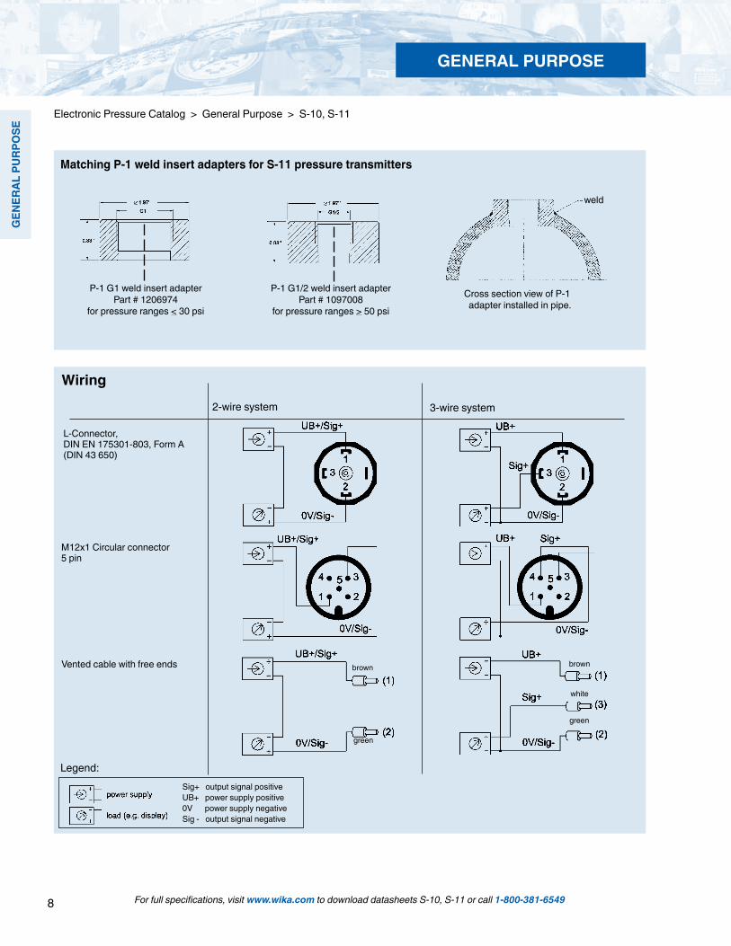
P-1 G1/2 weld insert adapterPart # 1097008
for pressure ranges > 50 psi
P-1 G1 weld insert adapterPart # 1206974
for pressure ranges < 30 psi
Cross section view of P-1 adapter installed in pipe.
weld
Matching P-1 weld insert adapters for S-11 pressure transmitters
Legend:
L-Connector, DIN EN 175301-803, Form A(DIN 43 650)
Wiring
M12x1 Circular connector5 pin
3-wire system2-wire system
Vented cable with free ends brownbrown
green
white
green
Sig+ output signal positiveUB+ power supply positive0V power supply negativeSig - output signal negative
For full specifications, visit www.wika.com to download datasheets S-10, S-11 or call 1-800-381-6549
GENERAL PURPOSE

9
GEN
ERAL PURPO
SE
Electronic Pressure Catalog > General Purpose > S-10
Type S-10 General Purpose Pressure Transmitters
Gauge Ranges Description Range Part #
0-50 InWC 8367656 0-100 InWC 8341481 0-5 psi 8415072 0-10 psi 8642885 0-15 psi 8643628 0-25 psi 8341995 0-30 psi 8643636 0-50 psi 8348868 0-60 psi 8643644 0-100 psi 8643652 0-160 psi 8341155 0-200 psi 8644918 0-250 psi 8341163 0-300 psi 8341732 0-400 psi 8341953 0-500 psi 8341740 0-600 psi 8347128 0-750 psi 4294930 0-1,000 psi 8610007 0-1,500 psi 8341219 0-2,000 psi 8353098 0-3,000 psi 8342275 0-5,000 psi 8340638 0-8,000 psi 8341864 0-10,000 psi 8347242 0-15,000 psi 8359143
Vacuum & Compound Ranges Description Range Part # 30"-0 HgVac 8642850 30"-0-30 psi 8415080 30"-0-60 psi 8415099 30"-0-100 psi 8648646 30"-0-160 psi 9796881 30"-0-200 psi 8985538
Absolute Pressure Ranges Description Range Part # 0-15 psia 8587582 0-25 psia 8358503 0-50 psia 8347854 0-100 psia 9734538 0-250 psia 9734589 0-500 psia 9767164
Standard Features
Signal output: 4-20 mA 2-wire Supply voltage: 10-30 VDC Process connection: 1/2 NPT male Electrical connection: DIN EN 175301-803 (DIN 43 650) with plug connector
For full specifications, visit www.wika.com to download datasheet S-10 or call 1-800-381-6549
GENERAL PURPOSE
10
GEN
ERAL
PU
RPO
SE
For full specifications, visit www.wika.com to download datasheets S-10 or call 1-800-381-6549
GENERAL PURPOSE
Electronic Pressure Catalog > General Purpose > S-10
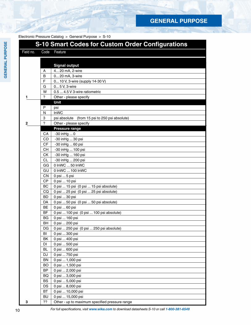
S-10 Smart Codes for Custom Order Configurations Field no. Code Feature
Signal output A 4... 20 mA, 2-wire B 0... 20 mA, 3-wire F 0... 10 V, 3-wire (supply 14-30 V) G 0... 5 V, 3-wire W 0.5 ... 4.5 V 3-wire ratiometric 1 ? Other - please specify Unit P psi N InWC 3 psi absolute (from 15 psi to 250 psi absolute) 2 ? Other - please specify Pressure range CA -30 inHg ... 0 CD -30 inHg ... 30 psi CF -30 inHg ... 60 psi CH -30 inHg ... 100 psi CK -30 inHg ... 160 psi CL -30 inHg ... 200 psi GG 0 InWC ... 50 InWC GU 0 InWC ... 100 InWC CN 0 psi ... 5 psi CP 0 psi ... 10 psi BC 0 psi ... 15 psi (0 psi ... 15 psi absolute) CQ 0 psi ... 25 psi (0 psi ... 25 psi absolute) BD 0 psi ... 30 psi DA 0 psi ... 50 psi (0 psi ... 50 psi absolute) BE 0 psi ... 60 psi BF 0 psi ... 100 psi (0 psi ... 100 psi absolute) BG 0 psi ... 160 psi BH 0 psi ... 200 psi DG 0 psi ... 250 psi (0 psi ... 250 psi absolute) BI 0 psi ... 300 psi BK 0 psi ... 400 psi DI 0 psi ... 500 psi BL 0 psi ... 600 psi DJ 0 psi ... 750 psi BN 0 psi ... 1,000 psi BO 0 psi ... 1,500 psi BP 0 psi ... 2,000 psi BQ 0 psi ... 3,000 psi BS 0 psi ... 5,000 psi DS 0 psi ... 8,000 psi BT 0 psi ... 10,000 psi BU 0 psi ... 15,000 psi 3 ?? Other - up to maximum specified pressure range
11
GEN
ERAL PURPO
SE
For full specifications, visit www.wika.com to download datasheet S-10 or call 1-800-381-6549
Electronic Pressure Catalog > General Purpose > S-10
GENERAL PURPOSE
Field no. Code Feature Additional price
S-10 Smart Codes for Custom Order Configurations (cont') Field no. Code Feature
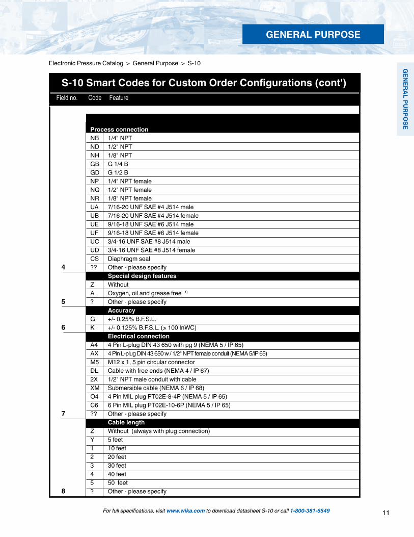
Process Process connection NB 1/4" NPT ND 1/2" NPT NH 1/8" NPT GB G 1/4 B GD G 1/2 B NP 1/4" NPT female NQ 1/2" NPT female NR 1/8" NPT female UA 7/16-20 UNF SAE #4 J514 male UB 7/16-20 UNF SAE #4 J514 female UE 9/16-18 UNF SAE #6 J514 male UF 9/16-18 UNF SAE #6 J514 female UC 3/4-16 UNF SAE #8 J514 male UD 3/4-16 UNF SAE #8 J514 female CS Diaphragm seal 4 ?? Other - please specify Special design features Z Without A Oxygen, oil and grease free 1) 5 ? Other - please specify Accuracy G +/- 0.25% B.F.S.L. 6 K +/- 0.125% B.F.S.L. (> 100 InWC) Electrical connection A4 4 Pin L-plug DIN 43 650 with pg 9 (NEMA 5 / IP 65) AX 4 Pin L-plug DIN 43 650 w / 1/2" NPT female conduit (NEMA 5/IP 65) M5 M12 x 1, 5 pin circular connector DL Cable with free ends (NEMA 4 / IP 67) 2X 1/2" NPT male conduit with cable XM Submersible cable (NEMA 6 / IP 68) O4 4 Pin MIL plug PT02E-8-4P (NEMA 5 / IP 65) C6 6 Pin MIL plug PT02E-10-6P (NEMA 5 / IP 65) 7 ?? Other - please specify Cable length Z Without (always with plug connection) Y 5 feet 1 10 feet 2 20 feet 3 30 feet 4 40 feet 5 50 feet 8 ? Other - please specify
12
GEN
ERAL
PU
RPO
SE
For full specifications, visit www.wika.com to download datasheet S-10 or call 1-800-381-6549
Electronic Pressure Catalog > General Purpose > S-10
GENERAL PURPOSE
1 2 3 4 5 6 7 8 9 10 11 12 13*Order Code:
S-10 - - - - -
*Additional order details
Field no. Code Feature
S-10 Smart Codes for Custom Order Configurations (cont')
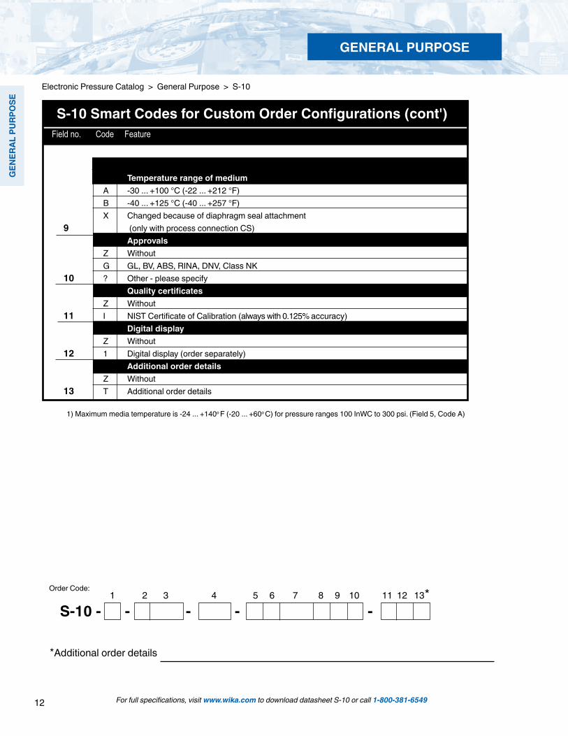
1) Maximum media temperature is -24 ... +140o F (-20 ... +60o C) for pressure ranges 100 InWC to 300 psi. (Field 5, Code A)
T Temperature range of medium A -30 ... +100 °C (-22 ... +212 °F) B -40 ... +125 °C (-40 ... +257 °F) X Changed because of diaphragm seal attachment9 (only with process connection CS) Approvals Z Without G GL, BV, ABS, RINA, DNV, Class NK 10 ? Other - please specify Quality certificates Z Without 11 I NIST Certificate of Calibration (always with 0.125% accuracy) Digital display Z Without 12 1 Digital display (order separately) Additional order details Z Without 13 T Additional order details

13
GEN
ERAL PURPO
SE
Gauge Ranges Description Range Part # Vacuum & Compound Ranges
Description Range Part #
0-50 InWC1 9739640 0-100 InWC1 8341473 0-5 psi1 4204051 0-10 psi1 8341074 0-15 psi1 8345726 0-25 psi1 8395736 0-30 psi1 7113644 0-50 psi 8395766 0-60 psi 8351312 0-100 psi 8341724 0-160 psi 8643407 0-200 psi 8641064 0-250 psi 8341961 0-300 psi 8341171 0-400 psi 8342003 0-500 psi 8341197 0-600 psi 8345745 0-750 psi 8352865 0-1,000 psi 9777517 0-1,500 psi 8366706 0-2,000 psi 8640823 0-3,000 psi 8341758 0-5,000 psi 8340646 0-8,000 psi 9749581
30"-0 HgVac1 839570630"-0-30 psi 9796058 30"-0-60 psi 834562230"-0-100 psi 8340242 30"-0-200 psi 8342118
Standard Features
Signal output: 4-20 mA 2-wire Supply voltage: 10-30 VDC Electrical connection: DIN EN 175301-803 (DIN 43 650) with plug connector Process connection: G1B or G1/2B depending upon pressure range
NOTES:1Pressure ranges from 50 InWC to 25 psi are supplied with G1B flush process connections; see datasheet for details
For full specifications, visit www.wika.com to download datasheet S-11 or call 1-800-381-6549
Electronic Pressure Catalog > General Purpose > S-11
Type S-11 Flush Diaphragm Pressure Transmitter
GENERAL PURPOSE

14
GEN
ERAL
PU
RPO
SE
For full specifications, visit www.wika.com to download datasheet S-11 or call 1-800-381-6549
GENERAL PURPOSE
S-11 Smart Codes for Custom Order Configurations Field no. Code Feature
Signal output A 4 ... 20 mA, 2-wire B 0 ... 20 mA, 3-wire F 0 ... 10 V, 3-wire (Supply 14-30 V) G 0 ... 5 V, 3-wire W 0.5 ... 4.5 V 3-wire ratiometric1 ? Other - please specify Unit P psi N InWC 3 psi absolute (from 15 psi to 250 psi absolute)2 ? Other - please specify Pressure range CA -30 inHg ... 0 CD -30 inHg ... 30 psi CF -30 inHg ... 60 psi CH -30 inHg ... 100 psi CK -30 inHg ... 160 psi CL -30 inHg ... 200 psi GG 0 InWC ... 50 InWC GU 0 InWC ... 100 InWC CN 0 psi ... 5 psi CP 0 psi ... 10 psi BC 0 psi ... 15 psi (0 psi ... 15 psi absolute) CQ 0 psi ... 25 psi (0 psi ... 25 psi absolute) BD 0 psi ... 30 psi DA 0 psi ... 50 psi (0 psi ... 50 psi absolute) BE 0 psi ... 60 psi BF 0 psi ... 100 psi (0 psi ... 100 psi absolute) BG 0 psi ... 160 psi BH 0 psi ... 200 psi DG 0 psi ... 250 psi (0 psi ... 250 psi absolute) BI 0 psi ... 300 psi BK 0 psi ... 400 psi DI 0 psi ... 500 psi BL 0 psi ... 600 psi DJ 0 psi ... 750 psi BN 0 psi ... 1,000 psi BO 0 psi ... 1,500 psi3 BP 0 psi ... 2,000 psi
TRONIC > General Purpose > S-11
15
GEN
ERAL PURPO
SE
TRONIC > General Purpose > S-11
For full specifications, visit www.wika.com to download datasheet S-11 or call 1-800-381-6549
GENERAL PURPOSE
S-11 Smart Codes for Custom Order Configurations (cont'd) Field no. Code Feature
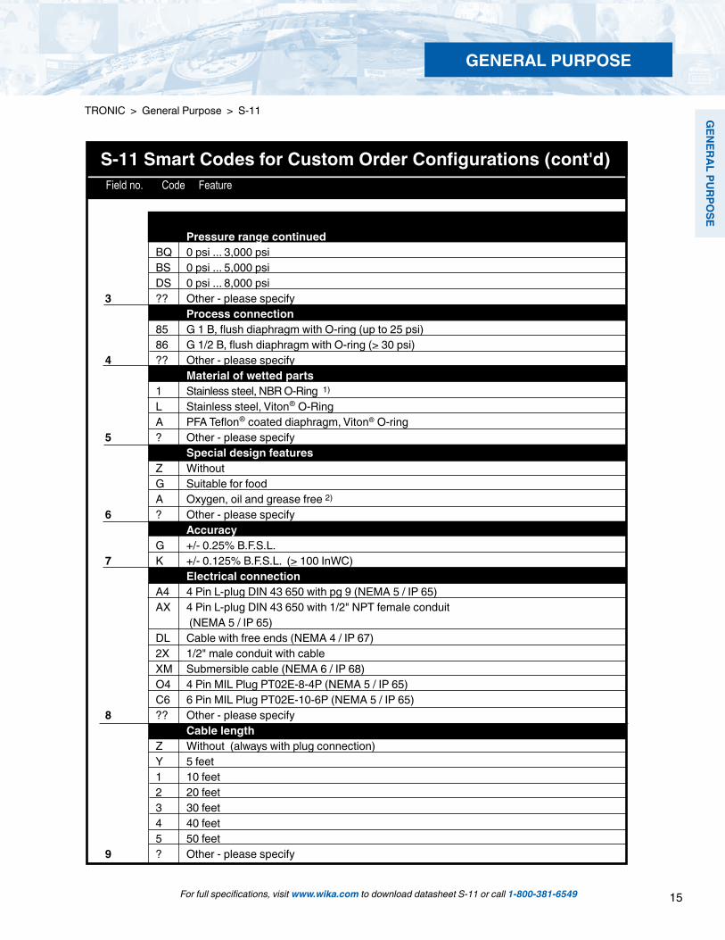
Pressure range continued BQ 0 psi ... 3,000 psi BS 0 psi ... 5,000 psi DS 0 psi ... 8,000 psi3 ?? Other - please specify Process connection 85 G 1 B, flush diaphragm with O-ring (up to 25 psi) 86 G 1/2 B, flush diaphragm with O-ring (> 30 psi)4 ?? Other - please specify Material of wetted parts 1 Stainless steel, NBR O-Ring 1)
L Stainless steel, Viton® O-Ring A PFA Teflon® coated diaphragm, Viton® O-ring5 ? Other - please specify Special design features Z Without G Suitable for food A Oxygen, oil and grease free 2)
6 ? Other - please specify Accuracy G +/- 0.25% B.F.S.L.7 K +/- 0.125% B.F.S.L. (> 100 InWC) Electrical connection A4 4 Pin L-plug DIN 43 650 with pg 9 (NEMA 5 / IP 65) AX 4 Pin L-plug DIN 43 650 with 1/2" NPT female conduit (NEMA 5 / IP 65) DL Cable with free ends (NEMA 4 / IP 67) 2X 1/2" male conduit with cable XM Submersible cable (NEMA 6 / IP 68) O4 4 Pin MIL Plug PT02E-8-4P (NEMA 5 / IP 65) C6 6 Pin MIL Plug PT02E-10-6P (NEMA 5 / IP 65)8 ?? Other - please specify Cable length Z Without (always with plug connection) Y 5 feet 1 10 feet 2 20 feet 3 30 feet 4 40 feet 5 50 feet9 ? Other - please specify
16
GEN
ERAL
PU
RPO
SE
1 2 3 4 5 6 7 8 9 10 11 12 13 14*Order Code:
S-11 - - - - -
*Additional order details
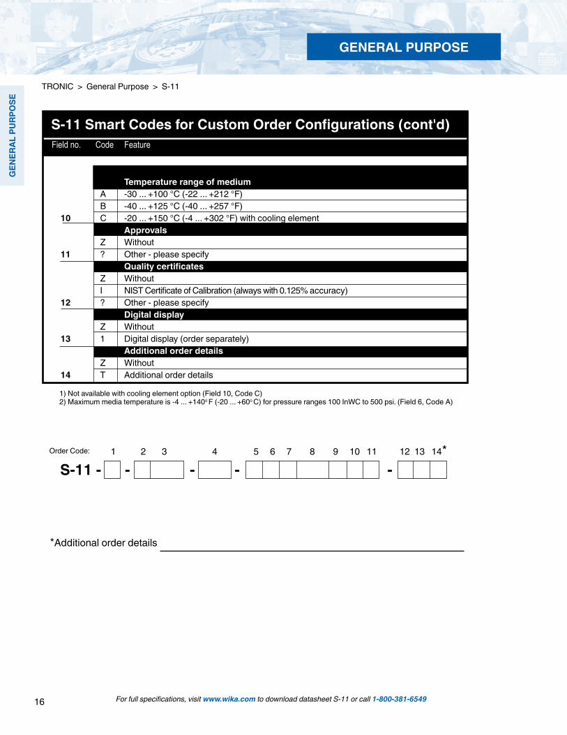
1) Not available with cooling element option (Field 10, Code C) 2) Maximum media temperature is -4 ... +140o F (-20 ... +60o C) for pressure ranges 100 InWC to 500 psi. (Field 6, Code A)
S-11 Smart Codes for Custom Order Configurations (cont'd) Field no. Code Feature
Temperature range of medium A -30 ... +100 °C (-22 ... +212 °F) B -40 ... +125 °C (-40 ... +257 °F)10 C -20 ... +150 °C (-4 ... +302 °F) with cooling element Approvals Z Without11 ? Other - please specify Quality certificates Z Without I NIST Certificate of Calibration (always with 0.125% accuracy)12 ? Other - please specify Digital display Z Without13 1 Digital display (order separately) Additional order details Z Without14 T Additional order details
For full specifications, visit www.wika.com to download datasheet S-11 or call 1-800-381-6549
GENERAL PURPOSE
TRONIC > General Purpose > S-11

17
GEN
ERAL PURPO
SE
For full specifications, visit www.wika.com to download datasheet F-20 or call 1-800-381-6549
Electronic Pressure Catalog > General Purpose > F-20, F-21
Type F-20, F-21 General Purpose Pressure Transmitters with NEMA 4X Integral Junction Box
Left: F-20 with standard NPT connectionRight: F-21 with flush diaphragm
Applications
Chemical industry Food industry Pharmaceutical industry Corrosive environments Mechanical engineering
Special Features
Pressure ranges from 50 InWC to 15,000 psi 4-20mA and voltage signal outputs available Compact size and rugged construction All stainless steel design Integral electrical connection
Description
Compact, rugged designThe F-2X series of pressure transmitters are designed for installation in difficult, corrosive environments. The smooth exterior surfaces reduce areas where contaminants may collect and make it ideal for use in the food and pharmaceutical industries where wash-down procedures for cleanliness are required.
The all stainless steel case meets NEMA 4X requirements for wash-down and corrosion resistance and ingress protection is available up to IP 67.
Easily accessible electrical connectionThe sophisticated design of this transmitter provides for fast, easy installation. The junction box cover unscrews for access to the internal spring clip terminal block.
Additional featuresTransmitters with the 4-20mA output signal include an internal test circuit connection that permits the transmit-ter to be tested without disconnecting the primary 4-20 mA circuit. The model F-20 features an all-welded stainless steel measuring cell for improved media compatibility. There are no internal soft sealing materials that may react with the media or deteriorate over time.
The model F-21 features a flush diaphragm process connection. This flat sensing surface is specifically designed for the measurement of viscous fluids or media containing solids that may clog the NPT process connection.
GENERAL PURPOSE

18
GEN
ERAL
PU
RPO
SE
For full specifications, visit www.wika.com to download datasheet F-20 or call 1-800-381-6549
Specifications Model F-20, F-21
Pressure range 50 InWC 5 psi 10 psi 25 psi 30 psi 60 psi 100 psi 160 psi 200 psiMaximum pressure* 15 psi 29 psi 58 psi 145 psi 145 psi 240 psi 500 psi 1,160 psi 1,160 psiBurst pressure** 29 psi 35 psi 69 psi 170 psi 170 psi 290 psi 600 psi 1,390 psi 1,390 psiPressure range 300 psi 500 psi 1,000 psi 2,000 psi 3,000 psi 5,000 psi 8,000 psi 10,000 psi1 15,000 psi1Maximum pressure* 1,160 psi 1,160 psi 1,740 psi 4,600 psi 7,200 psi 11,600 psi 17,400 psi 17,400 psi 21,750 psiBurst pressure** 1,390 psi 5,800 psi 7,970 psi 14,500 psi 17,400 psi 24,650 psi 34,800 psi 34,800 psi 43,500 psivacuum, gauge pressure, compound ranges, and absolute pressure references are available1 Ranges only available with type F-202 For type F-21 the burst pressure is limited to 21,000psi unless the pressure seal is accomplished by using the sealing ring underneath the hex.*Pressure applied up to the maximum rating will cause no permanent change in specifications but may lead to zero and span shifts**Exceeding the burst pressure may result in destruction of the transmitter and possible loss of mediaMaterials Wetted parts (for other materials see WIKA diaphragm seal program) type F-20 Stainless steel type F-21 Stainless steel; O-ring: NBR Viton® or EPDM Case Stainless steelInternal transmission fluid 3) Synthetic oil Halocarbon® oil for oxygen applications 4)
Listed by FDA for food applications3) Not available with F-20 on pressure ranges >300 psi4) Media temperature for oxygen version: -4 ... +140 °F / -20 ... +60 °C Not available in vacuum and absolute pressure ranges or with type F-21 flush diaphragm version > 500 psi
Power supply UB DC V 10 < UB ≤ 30 (11 ... 30 with signal output 4 ... 20 mA, 14 ... 30 with signal output 0 ... 10 V)
Signal output and 4 ... 20 mA, 2-wire RA < (UB - 11 V) / 0.02 A with RA in Ohm and UB in Voltmaximum load RA 0 ... 20 mA, 3-wire RA < (UB - 3 V) / 0.02 A with RA in Ohm and UB in Volt
0 ... 5 V, 3-wire RA > 5 kOhm, 0 ... 10 V, 3-wire RA > 10 kOhmTest circuit signal / max. load RA Only for instruments with 4 ... 20 mA signal output. RA < 15 Ohm Adjustability zero/span % ± 5 using potentiometers inside the instrumentResponse time (10 ... 90 %) 7) ms < 1 Isolation voltage DC V 500Accuracy 5) % of span ≤ 0.25 0.125 6) (BFSL)
% of span ≤ 0.5 0.25 6) (limit point calibration)5) Including linearity, hysteresis and repeatability. Limit point calibration performed in vertical mounting position with pressure connection facing down.6) For pressure ranges above 100 InWC
Non-linearity % of span ≤ 0.2 (BFSL) according to IEC 61-298-2Non-repeatability % of span ≤ 0.11-year stability % of span ≤ 0.2 (at reference conditions)Permissible temperature of Medium -22 ... +212 °F -40 ... +257 °F 7) -30 ... +100 °C -40 ... +125 °C 7)
Ambient -4 ... +176 °F -22 ... +221 °F -20 ... +80 °C -30 ... +105 °C Storage -40 ... +212 °F -40 ... +100 °CCompensated temperature range 32 ... +176 °F 0 ... +80 °C
Also complies with EN 50178, Tab. 7, Type C, Class 4KH Operation, 1K4 Storage, 1K3 Transport7) Response time F-20: < 10 ms at medium temperatures below -30 °C (-22 °F) for pressure ranges up to 300 psi Response time F-21: < 10 ms at medium temperatures below -30 °C (-22 °F)
Temperature coefficients (TC) withincompensated temperature range: Mean TC of zero % of span ≤ 0.2 / 10 K (<0.4 for pressure range < 100 InWC) Mean TC of range % of span ≤ 0.2 / 10 KCE- conformity Pressure equipment directive 97/23/EC EMC directive 89/336/EEC emission (class B) and immunity according to EN 61 326
Shock resistance g 600 according to IEC 60028-2-27 (mechanical shock)Vibration resistance g 10 according to IEC 60068-2-6 (vibration under resonance)Wiring protection Protected against reverse polarity, overvoltage and short circuitingElectrical connection Internal spring clip terminals; wire cross section 2.5 mm2 max, internal ground
Terminal for brass nickel-plated or stainless steel threaded connectionadditional external ground terminal for stainless steel threaded conduit connection
Weight lb Approx. 0.75
Items in curved brackets are optional extras at additional cost.
GENERAL PURPOSE
19
GEN
ERAL PURPO
SE
For full specifications, visit www.wika.com to download datasheet F-20 or call 1-800-381-6549
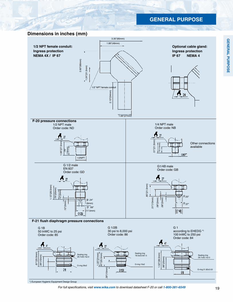
F-21 flush diaphragm pressure connections
2.60
”(66m
m)
1.24
”(31.
5mm
)
1.89”(48mm)
3.35”(85mm)
1/2” NPT female conduit
2.13
”(54m
m)
1.06”(27mm)
1.08
”(27.
5mm
).7
5”
(19m
m)
1/2NPT.5
1”(2
1.5m
m)
.75”
(13m
m)
1.12
”(28.
5mm
)
.79”
(20m
m)
.12”
(3m
m)
.12”
(3m
m) O .24”
(6mm)O .69”
(17.5mm)
Sealing ring29.7x35.7x2.0
O-ring 26x2
G 1B50 InWC to 25 psiOrder code: 85
G 1/2B30 psi to 8,000 psiOrder code: 86
Sealing ring18.5x23.9x1.5
O-ring 15x2
G 1according to EHEDG *) 100 InWC to 250 psiOrder code: 84
.81”
(20.
5mm
)
.39”
(10m
m)
1.22
”(31m
m)
.81”
(20.
5mm
)
.39”
(10m
m)
Optional cable gland:Ingress protectionIP 67 NEMA 4
.85”
(21.
5mm
)
.51”
(13m
m)
.08”
(2m
m)
.08”
(2m
m) .20”
.37”
O
O
G1/4B maleOrder code: GB
Sealing ring29.7x35.7x2.0
O-ring 21.82x3.53
1.52
”(38.
5mm
)
.98”
(25m
m)
Dimensions in inches (mm)
1/2 NPT female conduit:Ingress protectionNEMA 4X / IP 67
*) European Hygienic Equipment Design Group
F-20 pressure connections
G 1/2 maleEN 837Order code: GD
1/2 NPT maleOrder code: ND
1/4 NPT maleOrder code: NB
Other connections available
GENERAL PURPOSE

20
GEN
ERAL
PU
RPO
SE
For full specifications, visit www.wika.com to download datasheet F-20 or call 1-800-381-6549
Electronic Pressure Catalog > General Purpose > F-20, F-21
Matching P-1 weld insert adapters for F-21 flush diaphragm transmitters
P-1 G1/2 weld insert adapterPart # 1097008
for pressure ranges > 30 psi
P-1 G1 weld insert adapterPart # 1206974
for pressure ranges < 25 psi
Legend:
Sig+ output signal positiveUB+ power supply positive0V power supply negativeSig - output signal negative
Cross section view of P-1 adapter installed in pipe.
weld
Types IS-20 -F, IS-21-Fsee datasheet IS-20
Wiring
3-wire system2-wire system
Related products:
CalibrationRemove the junction box cover. Attach a meter and power supply to the electrical connector. For gauge ranges the zero potentiometer can be adjusted to produce a null output when no pressure is applied. Span adjustment requires the use of a reference pressure source. Compound and absolute ranges require a vacuum and pressure source. When calibration is complete, reinstall the junction box cover hand tight.
Zero adjust
Spanadjust
spring clipterminal block
IS-20-F integral junction box version for installation in hazardous environments
GENERAL PURPOSE
21
GEN
ERAL PURPO
SE
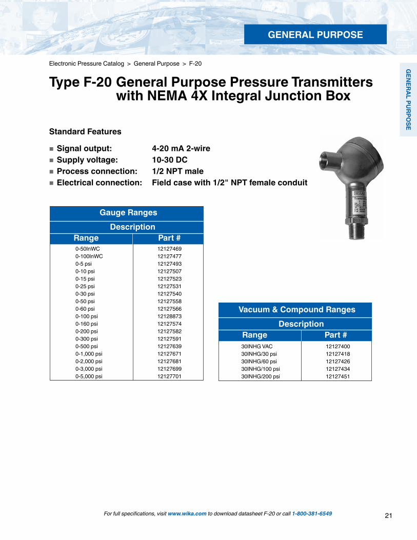
Vacuum & Compound Ranges Description Range Part #
30INHG VAC 12127400 30INHG/30 psi 12127418 30INHG/60 psi 12127426 30INHG/100 psi 12127434 30INHG/200 psi 12127451
Standard Features
Signal output: 4-20 mA 2-wire Supply voltage: 10-30 DC Process connection: 1/2 NPT male Electrical connection: Field case with 1/2" NPT female conduit
Gauge Ranges Description Range Part #
0-50InWC 12127469 0-100InWC 12127477 0-5 psi 121274930-10 psi 12127507 0-15 psi 12127523 0-25 psi 121275310-30 psi 121275400-50 psi 121275580-60 psi 121275660-100 psi 121288730-160 psi 121275740-200 psi 121275820-300 psi 12127591 0-500 psi 121276390-1,000 psi 121276710-2,000 psi 121276810-3,000 psi 121276990-5,000 psi 12127701
Electronic Pressure Catalog > General Purpose > F-20
Type F-20 General Purpose Pressure Transmitters with NEMA 4X Integral Junction Box
For full specifications, visit www.wika.com to download datasheet F-20 or call 1-800-381-6549
GENERAL PURPOSE

22
GEN
ERAL
PU
RPO
SE
For full specifications, visit www.wika.com to download datasheet F-20 or call 1-800-381-6549
GENERAL PURPOSE
Electronic Pressure Catalog > General Purpose > F-20
F-20 Smart Codes for Custom Order Configurations Field no. Code Feature
Signal output A 4 ... 20 mA, 2-wire B 0 ... 20 mA, 3-wire F 0 ... 10 V, 3-wire (Supply 14-30 V) G 0 ... 5 V, 3-wire1 ? Other - please specify Unit P psi N InWC 3 psi absolute2 ? Other - please specify Pressure range CA -30 inHg ... 0 CD -30 inHg ... 30 psi CF -30 inHg ... 60 psi CH -30 inHg ... 100 psi CK -30 inHg ... 160 psi CL -30 inHg ... 200 psi GG 0 InWC ... 50 InWC GU 0 InWC ... 100 InWC CN 0 psi ... 5 psi CP 0 psi ... 10 psi BC 0 psi ... 15 psi (0 psi ... 15 psi absolute) CQ 0 psi ... 25 psi (0 psi ... 25 psi absolute) BD 0 psi ... 30 psi DA 0 psi ... 50 psi (0 psi ... 50 psi absolute) BE 0 psi ... 60 psi BF 0 psi ... 100 psi (0 psi ... 100 psi absolute) BG 0 psi ... 160 psi BH 0 psi ... 200 psi DG 0 psi ... 250 psi (0 psi ... 250 psi absolute) BI 0 psi ... 300 psi BK 0 psi ... 400 psi DI 0 psi ... 500 psi BL 0 psi ... 600 psi DJ 0 psi ... 750 psi BN 0 psi ... 1,000 psi BO 0 psi ... 1,500 psi BP 0 psi ... 2,000 psi BQ 0 psi ... 3,000 psi BS 0 psi ... 5,000 psi3 DS 0 psi ... 8,000 psi

23
GEN
ERAL PURPO
SE
For full specifications, visit www.wika.com to download datasheet F-20 or call 1-800-381-6549
GENERAL PURPOSE
Electronic Pressure Catalog > General Purpose > F-20
1 2 3 4 5 6 7 8 9 10 11*
*Additional order details
Order Code:
F-20 - - - - -
F-20 Smart Codes for Custom Order Configurations (cont'd) Field no. Code Feature
1) Maximum media temperature is -4 ... +140o F (-20 ... +60o C) for pressure ranges 100 InWC to 300 psi.
Pressure range continued BT 0 psi ... 10,000 psi BU 0 psi ... 15,000 psi3 ?? Other - please specify Process connection ND 1/2" NPT NB 1/4" NPT GD G 1/2 B GB G 1/4 B CS Diaphragm seal4 ?? Other - please specify Special design features Z Without G Suitable for food A Oxygen, oil and grease free 1)
5 ?? Other - please specify Accuracy G +/- 0.25% B.F.S.L.6 K +/- 0.125% B.F.S.L. Electrical connection FE 1/2" NPT female conduit (IP67) FH Nickel plated brass cable gland (IP68) FC Stainless steel cable gland (IP68)7 ?? Other - please specify Temperature range of medium A -30 ... +100 °C (-22 ... +212 °F) B -40 ... +125 °C (-40 ... +257 °F)8 X Changed because of diaphragm seal attachment Quality certificates Z Without9 I NIST Certificate of Calibration (always with 0.125% accuracy) Digital display Z Without10 1 Digital display (order separately) Additional order details Z Without11 T Additional order details

24
GEN
ERAL
PU
RPO
SE
Standard Features
Signal output: 4-20 mA 2-wire Supply voltage: 10-30 DC Process connection: G1/2B or G1B flush diaphragm depending upon pressure range Electrical connection: Field case with 1/2" NPT female conduit
Gauge Ranges Description Range Part #
0-50 InWC1 121263310-5 psi1 12127728
0-10 psi1 12127736 0-100 psi 12127744
Electronic Pressure Catalog > General Purpose > F-21
Type F-21 Flush Diaphragm Pressure Transmitters with NEMA 4X Integral Junction Box
For full specifications, visit www.wika.com to download datasheet F-21 or call 1-800-381-6549
GENERAL PURPOSE

25
GEN
ERAL PURPO
SE
For full specifications, visit www.wika.com to download datasheet F-21 or call 1-800-381-6549
GENERAL PURPOSE
Electronic Pressure Catalog > General Purpose > F-21
F-21 Smart Codes for Custom Order Configurations Field no. Code Feature
Signal output A 4 ... 20 mA, 2-wire B 0 ... 20 mA, 3-wire F 0 ... 10 V, 3-wire (Supply 14-30 V) G 0 ... 5 V, 3-wire1 ? Other - please specify Unit P psi N InWC 3 psi absolute2 ? Other - please specify Pressure range CA -30 inHg ... 0 CD -30 inHg ... 30 psi CF -30 inHg ... 60 psi CH -30 inHg ... 100 psi CK -30 inHg ... 160 psi CL -30 inHg ... 200 psi GG 0 InWC ... 50 InWC GU 0 InWC ... 100 InWC CN 0 psi ... 5 psi CP 0 psi ... 10 psi BC 0 psi ... 15 psi (0 psi ... 15 psi absolute) CQ 0 psi ... 25 psi (0 psi ... 25 psi absolute) BD 0 psi ... 30 psi DA 0 psi ... 50 psi (0 psi ... 50 psi absolute) BE 0 psi ... 60 psi BF 0 psi ... 100 psi (0 psi ... 100 psi absolute) BG 0 psi ... 160 psi BH 0 psi ... 200 psi DG 0 psi ... 250 psi (0 psi ... 250 psi absolute) BI 0 psi ... 300 psi BK 0 psi ... 400 psi BL 0 psi ... 600 psi DJ 0 psi ... 750 psi BN 0 psi ... 1,000 psi BO 0 psi ... 1,500 psi BP 0 psi ... 2,000 psi BQ 0 psi ... 3,000 psi BS 0 psi ... 5,000 psi DS 0 psi ... 8,000 psi3 ?? Other - please specify
26
GEN
ERAL
PU
RPO
SE
For full specifications, visit www.wika.com to download datasheet F-21 or call 1-800-381-6549
GENERAL PURPOSE
Electronic Pressure Catalog > General Purpose > F-21
1 2 3 4 5 6 7 8 9 10 11 12*
*Additional order details
Order Code:
F-21 - - - - -
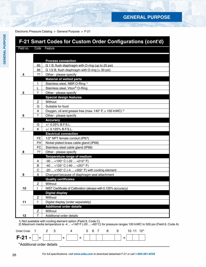
F-21 Smart Codes for Custom Order Configurations (cont'd) Field no. Code Feature
Process connection 85 G 1 B, flush diaphragm with O-ring (up to 25 psi) 86 G 1/2 B, flush diaphragm with O-ring (> 30 psi)4 ?? Other - please specify Material of wetted parts 1 Stainless steel, NBR O-Ring 1)
L Stainless steel, Viton® O-Ring5 ? Other - please specify Special design features Z Without G Suitable for food A Oxygen, oil and grease free (max. 140° F, > 100 InWC) 2)
6 ? Other - please specify Accuracy G +/- 0.25% B.F.S.L.7 K +/- 0.125% B.F.S.L. Electrical connection FE 1/2" NPT female conduit (IP67) FH Nickel plated brass cable gland (IP68) FC Stainless steel cable gland (IP68)8 ?? Other - please specify Temperature range of medium A -30 ... +100° C (-22 ... +212° F) B -40 ... +125° C (-40 ... +257° F) C -20 ... +150° C (-4 ... +302° F) with cooling element9 X Changed because of diaphragm seal attachment Quality certificates Z Without10 I NIST Certificate of Calibration (always with 0.125% accuracy) Digital display Z Without11 1 Digital display (order separately) Additional order details Z Without12 T Additional order details
1) Not available with cooling element option (Field 9, Code C) 2) Maximum media temperature is -4 ... +140o F (-20 ... +60o C) for pressure ranges 100 InWC to 500 psi (Field 6, Code A)

27
GEN
ERAL PURPO
SE
For full specifications, visit www.wika.com to download datasheet C-10 or call 1-800-381-6549
Standard ranges from 0…100 InWC to 0…15,000 psi Excellent shock and vibration resistance Environmental protection to NEMA 4 / IP 67 Stainless steel case and wetted parts
Hydraulics and pneumatics Mechanical engineering General industrial applications
Left: C-10 with MiniDIN connector Right: C-10 with optional cable
Applications
Special Features
Description
The WIKA C-10 provides performance and economy for a wide range of OEM applications. They are especially suited to applications subject to severe mechanical shock, vibration and electromagnetic interference. Typical applications include hydraulics and pneumatics, compressor controls, pump protection, refrigeration and air conditioning systems.
Dependable performance
The C-10 features an all-welded stainless steel measuring cell for improved media compatibility. There are no internal soft sealing materials that may react with the media or deteriorate over time. The case is also made of stainless steel and is available with environmental protection ratings up to NEMA 4 / IP 67.
Pressure ranges up to 300 psi use a piezoresistive measuring cell. The higher pressure ranges use thin film sensor technology. Both are time proven highly reliable sensor technologies.
A standard signal output of 4-20 mA allows the C-10 to be integrated into many existing applications. Many custom signal outputs, process connections and electrical connections are available.
Each C-10 undergoes extensive quality control testing and calibration to achieve an accuracy of < 0.50% full scale. The printed circuit boards use state-of-the-art surface mount technology. Each is individually temperature compensated to assure accuracy and long-term stability even when exposed to severe ambient temperature variations.
Electronic Pressure Catalog > General Purpose > C-10
Type C-10 General Purpose Pressure Transmitters
GENERAL PURPOSE

28
GEN
ERAL
PU
RPO
SE
permissible range
Supplyvoltage
Output signal and permissible load
Output current (2-wire)4 ... 20 mA: RA < (UB – 10 V) / 0.02 A
Output current (3-wire)0 ... 20 mA: RA < (UB - 3 V) / 0.02 A
Output voltage (3-wire)0 ... 5 V: RA >5 kOhm0 ... 10 V: RA >10 kOhm
4 ... 20 mA, 2-wire
Specifications Type C-10
Pressure range 100 InWC 5 psi 10 psi 15 psi 25 psi 30 psi 50 psi 100 psi 200 psiMaximum pressure* 29 psi 29 psi 58 psi 72 psi 145 psi 145 psi 240 psi 500 psi 1,160 psiBurst pressure** 34 psi 34 psi 69 psi 87 psi 170 psi 170 psi 290 psi 600 psi 1,390 psiPressure range 300 psi 500 psi 1,000 psi 2,000 psi 3,000 psi 5,000 psi 7,500 psi 10,000 psi 15,000 psiMaximum pressure* 1,160 psi 1,160 psi 1,740 psi 4,600 psi 7,200 psi 11,600 psi 17,400 psi 17,400 psi 21,750 psiBurst pressure** 1,390 psi 5,800 psi 7,970 psi 14,500 psi 17,400 psi 24,650 psi 34,800 psi 34,800 psi 43,500 psiabsolute pressure references are available*Pressure applied up to the maximum rating will cause no permanent change in specifications but may lead to zero and span shifts**Exceeding the burst pressure may result in destruction of the transmitter and possible loss of mediaMaterials Wetted parts Stainless steel Case Stainless steelInternal transmission fluid Synthetic oil, only for pressure ranges up to 0 ... 300 psi
Halocarbon® oil for oxygen applications 1)
Supply Voltage UB DC V 10 < UB ≤ 30 (14 ... 30 with signal output 0 ... 10 V)Response time (10 ... 90 %) ms < 1 (< 10 ms at medium temperatures below -22°F (-30°C) for pressure ranges up to 300 psi Accuracy 2) % of span ≤ 0.5 (BFSL)
% of span ≤ 01.0 2) Adjusted in vertical mounting position with lower pressure connection
Non-linearity % of span ≤ 0.4 (BFSL) according to IEC 61-298-2)1-year stability % of span ≤ 0.2 (at reference conditions)Permissible temperature of Medium -22 ... +212 °F -30 ... +100 °C Ambient -22 ... +185 °F -30 ... +85 °C Storage -40 ... +212 °F -40 ... +100 °CCompensated temperature range 0 ... +176 °F 0 ... +80 °CTemperature coefficients incompensated temp range Mean TC of zero % of span ≤ 0.3 / 10 K Mean TC of range % of span ≤ 0.2 / 10 KCE-conformity 89/336/EWG interference emission and immunity see EN 61326
97/23/EG Pressure equipment directiveShock resistance g 1,000 according to IEC 60068-2-27 (mechanical shock)Vibration resistance g 20 according to IEC 60068-2-6 (vibration under resonance)Wiring protection Protected against reverse polarity, overvoltage and short circuitingIngress protection Per IEC 60529 / EN 60529, see page 3Weight lb Approx. .22
1) Media temperature for oxygen version: -4 ... +140 °F (-20 ... 60 °C). Cannot be manufactured for absolute pressure ranges < 1 bar abs.2) Including linearity, hysteresis and repeatability. Limit point calibration in vertical mounting position with down pressure connection. Items in curved brackets are optional extras for additional price.
Electronic Pressure Catalog > General Purpose > C-10
For full specifications, visit www.wika.com to download datasheet C-10 or call 1-800-381-6549
GENERAL PURPOSE

29
GEN
ERAL PURPO
SE
Dimensions in inches (mm)
Pressure connections
Case
*) Mating connectors are not included
G 1/4 maleDIN 3852-EOrder code: HD
Electrical connections
Mini L-connectorG-series IP 65Order code: II
Circular connector,5-pin, M 12x1,IP 65 Order code: M5
Cable with Free EndsIP 65Order code: CR
*)
.55“
(14m
m)
.89“
(22.
5mm
)
G 1/4 maleEN 837Order code: GB
.85“
(21.
5mm
)
.51“
(13m
m)
.08“
(2m
m)
.08“
(2m
m)
.51“
(13m
m)
1/4” NPT maleOrder code: NB
.85“
(21.
5mm
)
1.34
“(34m
m)
1.06“(27mm)
1.14
“(29m
m)
1.06
“(27m
m)
2.20
“(56m
m)
1.46
“(37m
m)
Other process connections available
Electronic Pressure Catalog > General Purpose > C-10
For full specifications, visit www.wika.com to download datasheet C-10 or call 1-800-381-6549
GENERAL PURPOSE
30
GEN
ERAL
PU
RPO
SE
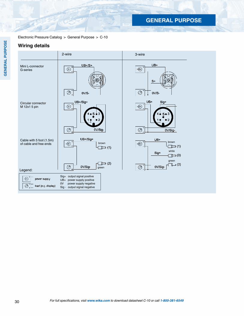
Electronic Pressure Catalog > General Purpose > C-10
Wiring details3-wire
Mini L-connectorG-series
2-wire
Cable with 5 foot (1.5m) of cable and free ends
Circular connectorM 12x1 5 pin
Legend:Sig+ output signal positiveUB+ power supply positive0V power supply negativeSig - output signal negative
brown
green
brown
green
white
For full specifications, visit www.wika.com to download datasheet C-10 or call 1-800-381-6549
GENERAL PURPOSE
31
GEN
ERAL PURPO
SE
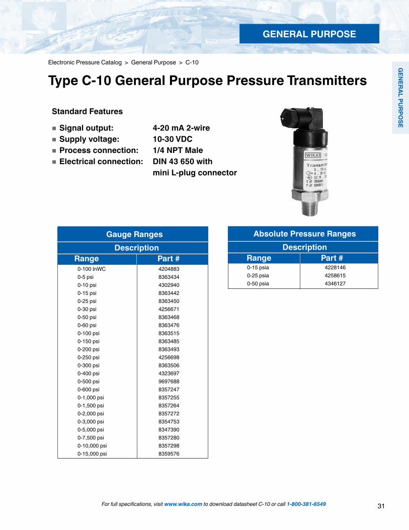
Gauge Ranges Description Range Part #
Absolute Pressure Ranges Description Range Part #
0-100 InWC 42048830-5 psi 83634340-10 psi 43029400-15 psi 83634420-25 psi 83634500-30 psi 42566710-50 psi 83634680-60 psi 83634760-100 psi 83635150-150 psi 83634850-200 psi 83634930-250 psi 42566980-300 psi 83635060-400 psi 43236970-500 psi 96976880-600 psi 83572470-1,000 psi 83572550-1,500 psi 83572640-2,000 psi 83572720-3,000 psi 83547530-5,000 psi 83473900-7,500 psi 83572800-10,000 psi 83572980-15,000 psi 8359576
0-15 psia 4228146 0-25 psia 4258615 0-50 psia 4346127
Standard Features
Signal output: 4-20 mA 2-wire Supply voltage: 10-30 VDC Process connection: 1/4 NPT Male Electrical connection: DIN 43 650 with mini L-plug connector
For full specifications, visit www.wika.com to download datasheet C-10 or call 1-800-381-6549
Electronic Pressure Catalog > General Purpose > C-10
Type C-10 General Purpose Pressure Transmitters
GENERAL PURPOSE

32
GEN
ERAL
PU
RPO
SE
For full specifications, visit www.wika.com to download datasheet C-10 or call 1-800-381-6549
GENERAL PURPOSE
Electronic Pressure Catalog > General Purpose > C-10
C-10 Smart Codes for Custom Order Configurations Field no. Code Feature
Signal output A 4... 20 mA, 2-wire G 0... 5 V, 3-wire F 0... 10 V, 3-wire (supply 14-30 V) W 0.5... 4.5V ratiometric1 ? Other - please specify Unit P psi N InWC 3 psi absolute (from 15 psi to 250 psi absolute)2 ? Other - please specify Pressure range GU 0 InWC ... 100 InWC CN 0 psi ... 5 psi CP 0 psi ... 10 psi BC 0 psi ... 15 psi (0 psi ... 15 psi absolute) CQ 0 psi ... 25 psi (0 psi ... 25 psi absolute) BD 0 psi ... 30 psi DA 0 psi ... 50 psi (0 psi ... 50 psi absolute) BE 0 psi ... 60 psi BF 0 psi ... 100 psi (0 psi ... 100 psi absolute) DC 0 psi ... 150 psi BH 0 psi ... 200 psi DG 0 psi ... 250 psi (0 psi ... 250 psi absolute) BI 0 psi ... 300 psi BK 0 psi ... 400 psi DI 0 psi ... 500 psi BL 0 psi ... 600 psi DJ 0 psi ... 750 psi BN 0 psi ... 1,000 psi BO 0 psi ... 1,500 psi BP 0 psi ... 2,000 psi BQ 0 psi ... 3,000 psi BS 0 psi ... 5,000 psi DS 0 psi ... 8,000 psi BT 0 psi ... 10,000 psi BU 0 psi ... 15,000 psi3 ?? Other - up to maximum specified pressure range

33
GEN
ERAL PURPO
SE
GENERAL PURPOSE
For full specifications, visit www.wika.com to download datasheet C-10 or call 1-800-381-6549
Electronic Pressure Catalog > General Purpose > C-10
C-10 Smart Codes for Custom Order Configurations (cont'd) Field no. Code Feature
Process connection NB 1/4" NPT ND 1/2" NPT NH 1/8" NPT GB G 1/4 B GD G 1/2 B NP 1/4" NPT female NQ 1/2" NPT female NR 1/8" NPT female UA 7/16-20 UNF SAE #4 J514 male UB 7/16-20 UNF SAE #4 J514 female UE 9/16-18 UNF SAE #6 J514 male UF 9/16-18 UNF SAE #6 J514 female UC 3/4-16 UNF SAE #8 J514 male UD 3/4-16 UNF SAE #8 J514 female 4 ?? Other - please specify Special design features Z Without A Oxygen, oil and grease free 1) 5 ? Other - please specify Electrical connection II DIN 43 650 with miniature L plug connector H2 4 Pin miniature L-Plug DIN 43 650 w/molded cable (NEMA 5 / IP 65) DL Cable with free ends (NEMA 4 / IP67) CR Cable with free ends (NEMA 5 / IP65) 2X 1/2" NPT male conduit with cable (NEMA 4 / IP67) M5 5 Pin locking plug M12 x 1 (NEMA 5 / IP 65) B5 5 Pin plug6 ?? Other - please specify Cable length Z Without Y 5 feet (only with H2, DL or CR) 1 10 feet (only with DL or CR) 2 20 feet (only with DL or CR) 3 30 feet (only with DL or CR) 4 40 feet (only with DL or CR) 5 50 feet (only with DL or CR)7 ? Other - please specify
34
GEN
ERAL
PU
RPO
SE
GENERAL PURPOSE
For full specifications, visit www.wika.com to download datasheet C-10 or call 1-800-381-6549
Electronic Pressure Catalog > General Purpose > C-10
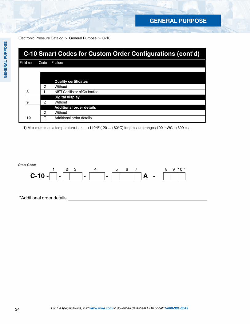
C-10 Smart Codes for Custom Order Configurations (cont'd) Field no. Code Feature
1 2 3 4 5 6 7 8 9 10 *
*Additional order details
Order Code:
C-10 - - - - A -
Quality certificates Z Without8 I NIST Certificate of Calibration Digital display9 Z Without Additional order details Z Without10 T Additional order details
1) Maximum media temperature is -4 ... +140o F (-20 ... +60o C) for pressure ranges 100 InWC to 300 psi.
35
GEN
ERAL PURPO
SE
For full specifications, visit www.wika.com to download datasheet A-10 or call 1-800-381-6549
Electronic Pressure Catalog > General Purpose > A-10
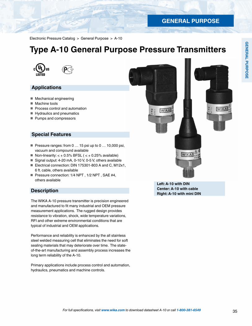
Type A-10 General Purpose Pressure Transmitters
Left: A-10 with DINCenter: A-10 with cableRight: A-10 with mini DIN
Applications
Mechanical engineering Machine tools Process control and automation Hydraulics and pneumatics Pumps and compressors
Special Features
Pressure ranges: from 0 … 15 psi up to 0 … 10,000 psi, vacuum and compound available
Non-linearity: < + 0.5% BFSL ( < + 0.25% available) Signal output: 4-20 mA, 0-10 V, 0-5 V, others available Electrical connection: DIN 175301-803 A and C, M12x1,
6 ft. cable, others available Pressure connection: 1/4 NPT , 1/2 NPT , SAE #4,
others available
Description
The WIKA A-10 pressure transmitter is precision engineered and manufactured to fit many industrial and OEM pressure measurement applications. The rugged design provides resistance to vibration, shock, wide temperature variations, RFI and other extreme environmental conditions that are typical of industrial and OEM applications.
Performance and reliability is enhanced by the all stainless steel welded measuring cell that eliminates the need for soft sealing materials that may deteriorate over time. The state-of-the-art manufacturing and assembly process increases the long term reliability of the A-10.
Primary applications include process control and automation, hydraulics, pneumatics and machine controls.
GENERAL PURPOSE

36
GEN
ERAL
PU
RPO
SE
For full specifications, visit www.wika.com to download datasheet A-10 or call 1-800-381-6549
Specifications Type A-10 Pressure ranges 15 psi 25 psi 30 psi 50 psi 100 psi 160 psi 200 psi 300 psiOver-pressure safety 30 psi 60 psi 60 psi 100 psi 200 psi 290 psi 400 psi 600 psiBurst pressure 75 psi 150 psi 150 psi 250 psi 500 psi 500 psi 1,500 psi 1,500 psiPressure ranges 500 psi 1,000 psi 1,500 psi 2,000 psi 3,000 psi 5,000 psi 10,000 psi Over-pressure safety 1,000 psi 1,740 psi 2,900 psi 4,000 psi 6,000 psi 10,000 psi 17,400 psi Burst pressure 2,500 psi 7,975 psi 11,600 psi 14,500 psi 17,400 psi 24,650 psi 34,800 psi Absolute pressure: 0 ... 15 psi up to 0 ... 300 psi. Vacuum and compound availableVacuum resistance Ranges greater than 150 psiFatigue life 10 million load cycles maximum Materials Wetted parts » Pressure connection 316 L » Pressure sensor 316 L (as of >0 ... 150 psig are PH 13-8 ss) Internal transmission fluid Silicone oil (only with pressure ranges < 0 ... 100 psig and < 0 ... 300 psi absolute) Case 316 LPower supply UB UB in VDC 8 ... 30 (14 ... 30 with signal output 0 ... 10 V) Maximum resistive load RA 4 ... 20mA, 2-wire RA < (UB-8V) / 0.02 A 0 ... 10 V, 3-wire RA > 10 k 0 ... 5 V, 3-wire RA > 5 k 1 ... 5 V, 3-wire RA > 5 k 0.5 ... 4.5 V, 3-wire RA > 4.5 k Other signal output on requestResponse time ms < 4Current consumption mA Signal current (max. 25) for current output (max. 8 for voltage output signal)Isolation voltage VDC 500 1)
1) For power supply, use a circuit with energy limitation (EN/UL/IEC 61010-1, section 9.3) with the following maximum values for the current: where UB = 30 V (DC): 5 A. Provide a separate switch for the external power supply. Alternative for North America: The connection may also be made to “Class 2 Circuits” or “Class 2 Power Units” according to CEC (Canadian Electrical Code) or NEC (National Electrical Code).Non-linearity % of span ≤ ± 0.5% BFSL according to IEC 61298-2 ≤ ± 0.25 BFSL according to IEC 61298-2Accuracy 2) % of span ≤ ± 1.0 (with 0.5% non-linearity)
≤ ± 0.5 (with 0.25% non-linearity) ≤ ± 0.6 (with 0.25% non-linearity and with signal output 0 ... 5 V) 2) Includes non-linearity, hysteresis, zero point and full scale error accordingly to IEC 61298-2
Calibrated in vertical mounting position with pressure connection facing down
Zero offset % of span ≤ 0.15 typ., ≤ 0.4 max. (with non-linearity 0.25%) ≤ 0.5 typ., ≤ 0.8 max. (with non-linearity 0.5%)Hysteresis % of span ≤ 0.16Non-repeatability % of span ≤ 0.1Long-term drift % of span ≤ 0.1 according to IEC 61298-2Signal noise % of span ≤ 0.3Permissible temperature of Medium 32 ... +176 °F -22 ... +212 °F 0 ... +80 °C -30 ... +100 °C Ambient 32 ... +176 °F -22 ... +212 °F 0 ... +80 °C -30 ... +100 °C Storage -4 ... +176 °F -22 ... +212 °F -20 ... +80 °C -30 ... +100 °COperating temperature range 32 ... +176 °F 0 ... +80 °CTemperature error within % of span ≤ 1.0 typ., ≤ 2.5 max.operating temperature range
Electronic Pressure Catalog > General Purpose > A-10
GENERAL PURPOSE

37
GEN
ERAL PURPO
SE
For full specifications, visit www.wika.com to download datasheet A-10 or call 1-800-381-6549
Specifications Type A-10 Approvals CULUS, GOST RoHS-conformity YesCE-conformity Pressure equipment directive 97/23/EC EMC directive 2004/108/EEC (Group 1, Class B) and immunity according to EN 61 326Shock resistance g 500 according to IEC 60068-2-27 (mechanical shock)Vibration resistance g 10 according to IEC 60068-2-6 (vibration under resonance)Wiring protection Overvoltage protection VDC 32; 36 with 4 ... 20 mA Short-circuit protection Sig+ to UB- Reverse polarity protection UB+ to UB-Test reference conditions According to IEC 61298-1 Relative humidity % 45 ... 75 Temperature % 59 ... 77 °F (15 ... 25 °C) Atmospheric pressure KPa 86 … 106 (25.4…31.3 inhg)Weight oz. Approx. 2.8 oz. (80 g)
Pressure connections 1/2 NPT MaleOrder Code: ND
7/16 - 20 UNFO-ring bossOrder Code: MV
1/4 NPT MaleOrder Code: NB
max. 1.9 (48 mm)
2.4
(60.
8 m
m)
1/4 NPT.51 (13 mm)
1.14 (29 mm)
EN175301-801-C
max. 1.5 (38 mm)
1.06 (27mm)
Dimensions in inches (mm) Items in curved brackets are optional extras for additional price.
DIN 175301-803 AL-connectorconductor outer diameter.24" to .32"IP 65Order Code: AG
DIN 175301-803 CL-connectorconductor outer diameter .18" to .24"IP 65Order Code: CG
M 12x1, 4 pinIP 67AG
Order Code: M4
Cable with free ends,conductor cross section .013 in 2, conductor outer diameter.26",PUR cable - unshielded, IP 67
Ingress protection IP per IEC 60529. The ingress protection classes specified only apply while the pressure transmitter is connected with female connectors that provide the equivalent ingress protection.
For tapped holes and welding sockets please see Technical Information IN 00.14 for download at www.wika.de
Electronic Pressure Catalog > General Purpose > A-10
GENERAL PURPOSE
1/4 NPT 1/4 NPT
Order Code: DL

38
GEN
ERAL
PU
RPO
SE
For full specifications, visit www.wika.com to download datasheet A-10 or call 1-800-381-6549
Electronic Pressure Catalog > General Purpose > A-10
Specifications and dimensions given in this datasheet represent the state of engineering at the time of printing.Modifications may take place and materials specified may be replaced by others without prior notice.
Electrical connections
G 1/2 BOrder Code: GD
M20 x 1.5with sealing ringOrder Code: MI
1/4" NPT femaleOrder Code: NP
Pressure connections
DIN 175301-803 AL-connectorIP 65
brown
blue
brown
blue
black
3-wire2-wire
DIN 175301-803 CL-connectorIP 65
M 12x1, 4-pinwithout angle socket or female cable connectorsIP 67
Cable with free endsIP 67
GENERAL PURPOSE

39
GEN
ERAL PURPO
SE
For full specifications, visit www.wika.com to download datasheet A-10 or call 1-800-381-6549
Electronic Pressure Catalog > General Purpose > A-10
Type A-10 General Purpose Pressure Transmitters
Standard Features
Signal output: 4-20 mA 2-wire or 0-10 V 3-wire Supply voltage: 8-30 DC (14-30 VDC) Process connection: 1/4 NPT Male Electrical connection: DIN EN 175301-803 (DIN 43 650) with plug connector Non-linearity: < +/- 0.5% B.F.S.L.
Description Range Part # 4-20 mA 2-wire 0-10 V 3-wire
0 ... 15 psia 50426354 50426737 0 ... 100 psia 50426389 504267610 ... 15 psi 50426397 50426770 0 ... 25 psi 50426401 839287880 ... 50 psi 50426427 504268000 ... 100 psi 50372475 504268180 ... 200 psi 50398083 504268340 ... 300 psi 50426460 50426842 0 ... 500 psi 50426478 504268510 ... 1,000 psi 50426486 504268690 ... 1,500 psi 50426494 504268770 ... 2,000 psi 50426508 504268850 ... 3,000 psi 50426516 504268930 ... 5,000 psi 50372483 504269070 ... 10,000 psi 50426532 50426915
GENERAL PURPOSE
40
GEN
ERAL
PU
RPO
SE
For full specifications, visit www.wika.com to download datasheet A-10 or call 1-800-381-6549
Electronic Pressure Catalog > General Purpose > A-10
GENERAL PURPOSE
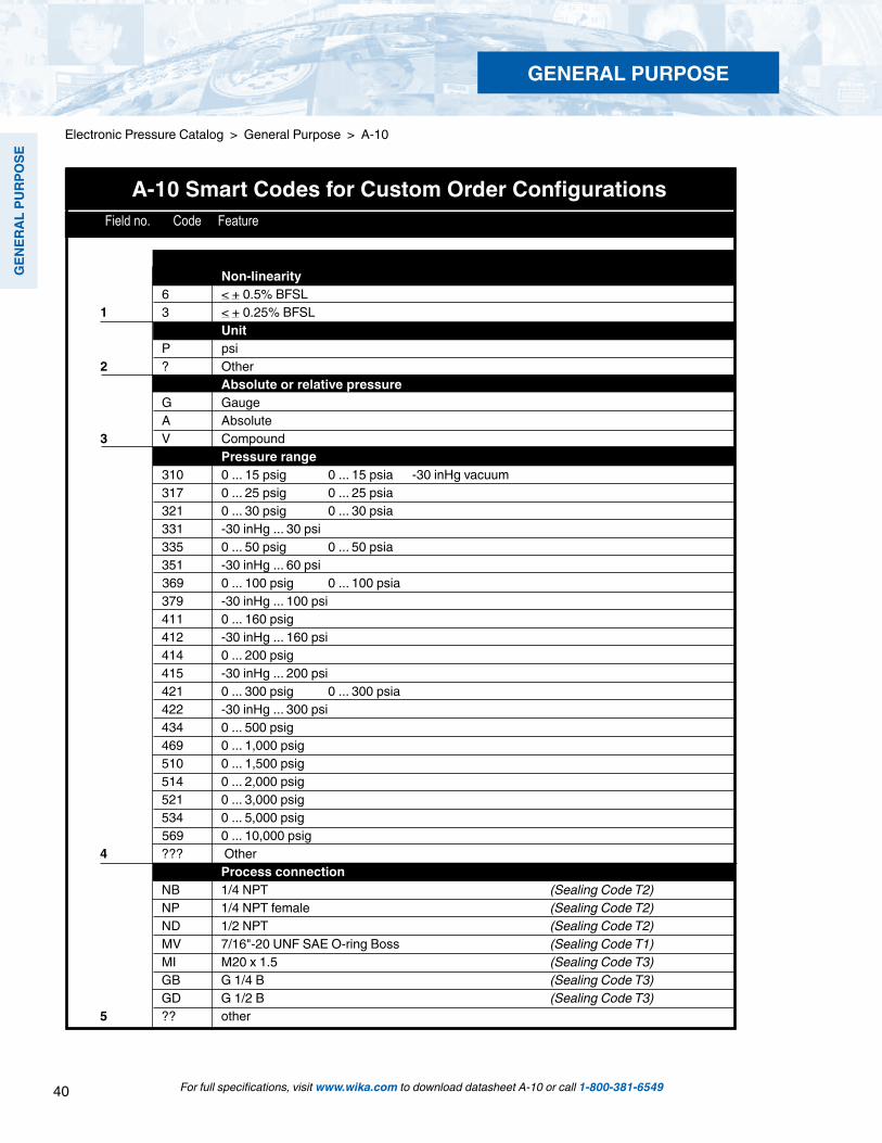
A-10 Smart Codes for Custom Order Configurations Field no. Code Feature
Non-linearity 6 < + 0.5% BFSL 1 3 < + 0.25% BFSL Unit P psi2 ? Other Absolute or relative pressure G Gauge A Absolute 3 V Compound Pressure range 310 0 ... 15 psig 0 ... 15 psia -30 inHg vacuum 317 0 ... 25 psig 0 ... 25 psia 321 0 ... 30 psig 0 ... 30 psia 331 -30 inHg ... 30 psi 335 0 ... 50 psig 0 ... 50 psia 351 -30 inHg ... 60 psi 369 0 ... 100 psig 0 ... 100 psia 379 -30 inHg ... 100 psi 411 0 ... 160 psig 412 -30 inHg ... 160 psi 414 0 ... 200 psig 415 -30 inHg ... 200 psi 421 0 ... 300 psig 0 ... 300 psia 422 -30 inHg ... 300 psi 434 0 ... 500 psig 469 0 ... 1,000 psig 510 0 ... 1,500 psig 514 0 ... 2,000 psig 521 0 ... 3,000 psig 534 0 ... 5,000 psig 569 0 ... 10,000 psig 4 ??? Other Process connection NB 1/4 NPT (Sealing Code T2) NP 1/4 NPT female (Sealing Code T2) ND 1/2 NPT (Sealing Code T2) MV 7/16"-20 UNF SAE O-ring Boss (Sealing Code T1) MI M20 x 1.5 (Sealing Code T3) GB G 1/4 B (Sealing Code T3) GD G 1/2 B (Sealing Code T3)5 ?? other

41
GEN
ERAL PURPO
SE
For full specifications, visit www.wika.com to download datasheet A-10 or call 1-800-381-6549
Electronic Pressure Catalog > General Purpose > A-10
GENERAL PURPOSE
1 2 3 4 5 6 7 8 9 10 11 12 13*
A-10 - - - - -
*Additional order details
Order Code:
A-10 Smart Codes for Custom Order Configurations (cont'd) Field no. Code Feature
Sealing L FPM/FKM (Use with Code T1) C Copper (Use with Code T3) S Stainless steel (Use with Code T3) 6 Z Without (Use with Code T2) Temperature range of medium Z 0...+80 °C (-32°F ... 176 °F) 7 A -30...+100 °C (-22°F ... 212 °F) Signal output A 4 ... 20 mA, 2-wire F 0 ... 10 V, 3-wire G 0 ... 5 V, 3-wire K 1 ... 5 V, 3-wire W 0.5 ... 4.5 V, 3-wire ratiometric8 ? Other Power supply A 8...30 V DC (only with signal outputs A, G, or K) C 14...30 V DC (only with signal output F) E 5 V DC +/- 10% (only with signal output W)9 ? Other Electrical connection AG Valve connector, size A AK Valve connector, size A with cable CG Valve connector, size C CK Valve connector, size C with cable M4 Circular connector M12x1, 4 pin MG Angled connector M12x1, 4 pin with cable MI Straight connector M12x1, 4 pin with cable10 DL Cable with free ends (IP 67) Cable length Z Without 6 6 feet (only with: AK,CK, MG, MI, or DL) 7 15 feet (only with: AK,CK, MG, MI, or DL)11 ? Other Certificates 12 Z Without Approvals S CULUS / GOST13 ? Other
42
GEN
ERAL
PU
RPO
SE
For full specifications, visit www.wika.com to download datasheet OT-1 or call 1-800-381-6549
Electronic Pressure Catalog > General Purpose > OT-1
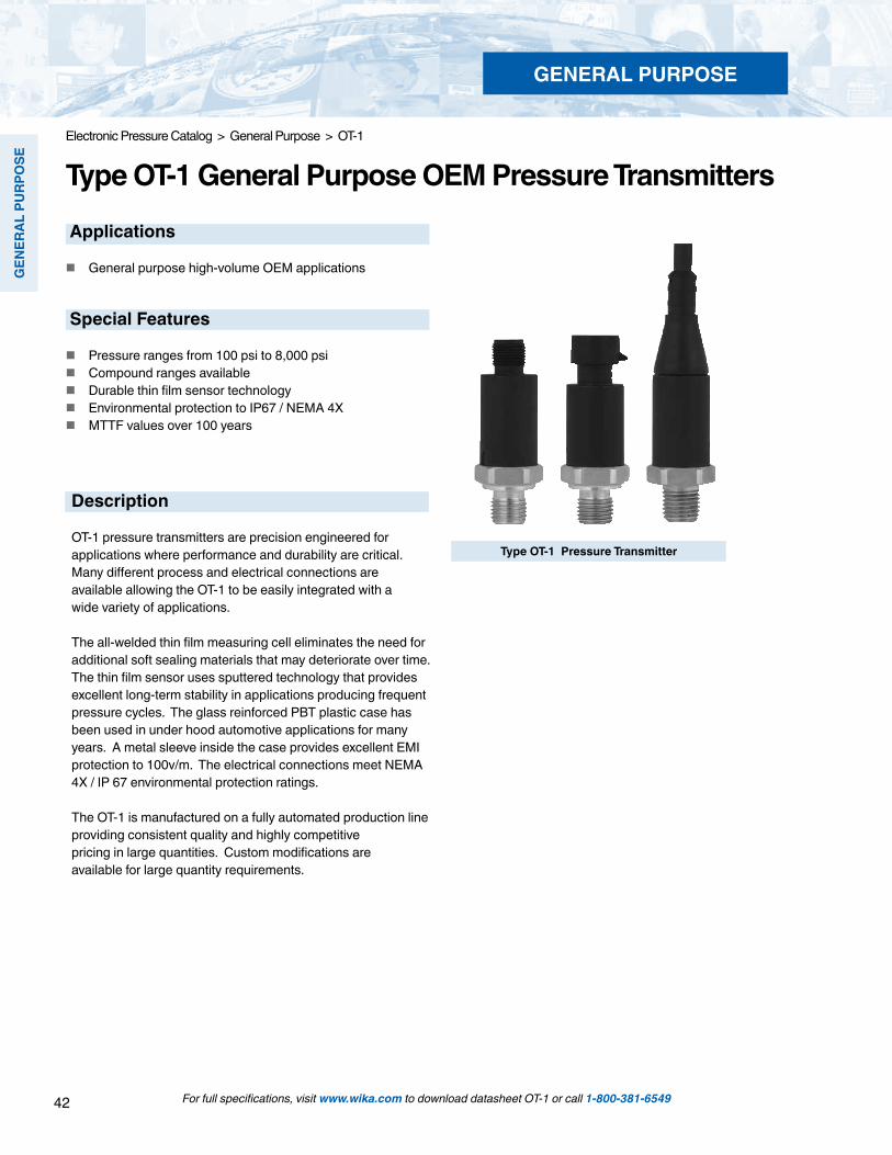
Type OT-1 General Purpose OEM Pressure TransmittersApplications
General purpose high-volume OEM applications
Special Features
Pressure ranges from 100 psi to 8,000 psi Compound ranges available Durable thin film sensor technology Environmental protection to IP67 / NEMA 4X MTTF values over 100 years
Type OT-1 Pressure Transmitter
GENERAL PURPOSE
Description
OT-1 pressure transmitters are precision engineered for applications where performance and durability are critical. Many different process and electrical connections are available allowing the OT-1 to be easily integrated with a wide variety of applications.
The all-welded thin film measuring cell eliminates the need for additional soft sealing materials that may deteriorate over time. The thin film sensor uses sputtered technology that provides excellent long-term stability in applications producing frequent pressure cycles. The glass reinforced PBT plastic case has been used in under hood automotive applications for many years. A metal sleeve inside the case provides excellent EMI protection to 100v/m. The electrical connections meet NEMA 4X / IP 67 environmental protection ratings.
The OT-1 is manufactured on a fully automated production line providing consistent quality and highly competitive pricing in large quantities. Custom modifications are available for large quantity requirements.

43
GEN
ERAL PURPO
SE
For full specifications, visit www.wika.com to download datasheet OT-1 or call 1-800-381-6549
Electronic Pressure Catalog > General Purpose > OT-1
Specifications Type OT-1
Pressure range -30 InHG/100 psi -30 InHG/200 psi 100 psi 150 psi 250 psi 300 psi 500 psiMaximum pressure* 290 psi 464 psi 290 psi 464 psi 725 psi 725 psi 1,160 psiBurst pressure** 1,450 psi 2,320 psi 1,450 psi 2,320 psi 3,625 psi 3,625 psi 5,800 psiPressure range 1,000 psi 1,500 psi 2,000 psi 3,000 psi 5,000 psi 7,500 psi 8,000 psiMaximum pressure* 1,740 psi 2,900 psi 4,600 psi 7,200 psi 11,600 psi 17,400 psi 17,400 psiBurst pressure** 7,970 psi 11,600 psi 14,500 psi 17,400 psi 24,650 psi 34,800 psi 34,800 psi*Pressure applied up to the maximum rating will cause no permanent change in specifications but may lead to zero and span shifts**Exceeding the burst pressure may result in destruction of the transmitter and possible loss of mediaMaterials: Wetted parts Stainless steel Case Fiberglass-reinforced polybutylene terephthalate (PBT) Signal output UR in DC V Signal output Power supply UB Maximum load RA
Power supply UB RA in Ohm 4 ... 20 mA, 2-wire 8 ... 36 DC V RA <(UB – 8 V) / 0.02 ASignal output and 1 ... 6 V, 3-wire 9 ... 36 DC V RA > 2,500Maximum load RA 1 ... 5 V, 3-wire 8 ... 36 DC V RA > 2,500
0 ... 10 V, 3-wire 14 ... 36 DC V RA > 5,0000.5 ... 4.5 V, ratiometric 5 + 0.5 DC V RA > 4,500
Response time (10 ... 90 %) ms < 2 Isolation voltage DC V 500Accuracy % of span < 0.5 (B.F.S.L)
% of span < 1.0 (limit point calibration)
(Includes non-linearity, hysteresis, zero point and full scale error per IEC 61298-2)
Non-repeatability % of span < 0.2Non-linearity % of span < 0.4 (B.F.S.L.) according to SEC 61298-21-year stability % of span < 0.3 (at reference conditions)Permissible temperature of: Media *) -40 ... +257 °F -40 ... +125 °C Ambient *) -40 ... +212 °F -40 ... +100 °C
With cable version limited temperature range from (-40 ... +194 °F) -40 ... +90 °C Storage *) -40 ... +248 °F -40 ... +120 °C
With cable version limited temperature range from (-40 ... +194 °F) -40 ... +90 °C *) Also complies with EN 50178, Tab. 7, Operation (C) 4K4H, Storage (D) 1K4, Transport (E) 2K3
Compensated temperature range +32 ... +176 °F 0 ... + 80 °CTemperature coefficients (TC) withincompensated temperature range: Mean TC of zero % of span < 0.15 / 10K (special pressure ranges may have increased zero TC) Mean TC of range % of span < 0.15 / 10K CE conformity Pressure equipment directive 97/23/EC
EMC directive 2004/108/EC, EN 61 326 Emission (Group 1, Class B) and Immunity (industrial locations)
Wiring protection Short-circuit protection Sig+ towards UB- Reverse polarity protection UB+ towards UB- (not with ratiometric signal output)Weight oz Approximately 2.1
GENERAL PURPOSE

44
GEN
ERAL
PU
RPO
SE
For full specifications, visit www.wika.com to download datasheet OT-1 or call 1-800-381-6549
Electronic Pressure Catalog > General Purpose > OT-1
1.83
“ (46
.5m
m)
2.64
“ (67
mm
)
Ø.80“ (20.2mm)
Ø.80“ (20.2mm) Ø.80“
(20.2mm)
Dimensions in inches (mm)
Circular connectorM 12x1, 4 pinIP 67Order code: M4
ConnectorMetri Pack Series 150IP 67Order code: R3
Cable with free endsIP 67Order code: DL
Pressure connections
Electrical connections Ingress Protection IP per IEC 60 529
1.70
“ (43
mm
)
1/4 NPT maleOrder code: NB
.7
6”
(19.
2mm
)
.7
1”
(18m
m)
.8
0”
(20.
2mm
)
.4
7”
(12m
m) Sealing ring
16,5 x 11, 6 x 1,5
G 1/4DIN 3852-E Order code: HD
G 1/4EN 837Order code: GB
.7
6”
(19.
2mm
)
.5
1”
(13m
m)
.0
8”
(2m
m)
.0
8”
(2m
m)
.98” (5mm)
.37” (9.5mm)
.4
7”
(12m
m)
.8
0”
(20.
2mm
)
M 14x1,5per DIN 3852-EOrder code: HN
Sealing ring16,5 x 11,6 x 1,5
SAE #4 7/16-20 UNF-2A male o-ring bossOrder code: MV
.6
9”
(17.
6mm
)
.3
6”
(9.1
4mm
)
GENERAL PURPOSE
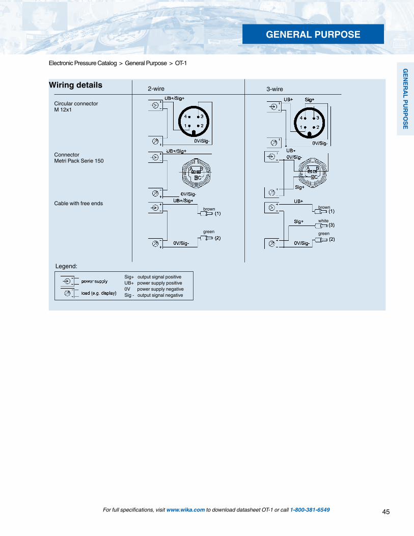
45
GEN
ERAL PURPO
SE
For full specifications, visit www.wika.com to download datasheet OT-1 or call 1-800-381-6549
Electronic Pressure Catalog > General Purpose > OT-1
Legend:Sig+ output signal positiveUB+ power supply positive0V power supply negativeSig - output signal negative
Wiring details
Circular connectorM 12x1
3-wire2-wire
Cable with free endsbrown
green
white
brown
green
ConnectorMetri Pack Serie 150
GENERAL PURPOSE

46
GEN
ERAL
PU
RPO
SE
For full specifications, visit www.wika.com to download datasheet OT-1 or call 1-800-381-6549
Electronic Pressure Catalog > General Purpose > OT-1
Type OT-1 General Purpose OEM Pressure Transmitters
Note: 50 piece minimum order quantity applies.
GENERAL PURPOSE
OT-1 Smart Codes for Custom Order Configurations Field no. Code Feature
Signal output A 4 ... 20 mA, 2-wire K 1 ... 5 V, 3-wire F 0 ... 10, 3-wire W 0.5-4.5V ratiometric1 ? Other - please specify Unit P psi2 ? Other - please specify Pressure range CH 30 inHg ... 100 psi CL 30 inHg ... 200 psi BF 0 psi ... 100 psi DC 0 psi ... 150 psi DG 0 psi ... 250 psi BI 0 psi ... 300 psi DI 0 psi ... 500 psi BN 0 psi ... 1,000 psi BO 0 psi ... 1,500 psi BP 0 psi ... 2,000 psi BQ 0 psi ... 3,000 psi BS 0 psi ... 5,000 psi DS 0 psi ... 8,000 psi3 ?? Other - please specify

47
GEN
ERAL PURPO
SE
For full specifications, visit www.wika.com to download datasheet OT-1 or call 1-800-381-6549
Electronic Pressure Catalog > General Purpose > OT-1
GENERAL PURPOSE
OT-1 Smart Codes for Custom Order Configurations (cont’d) Field no. Code Feature
1 2 3 4 5 6 7 8 9*
OT - 1 - - - - -
*Additional order details
Order Code:
Process connection NB 1/4" NPT MV 7/16-20 UNF SAE #4 Male w/O-ring boss GB G 1/4 B HD G 1/4 B DIN 3852-E HN M 14x1.5 DIN 3852-E4 ?? Other - please specify Electrical connection M4 4 Pin locking plug M12 x 1 (NEMA 4 / IP 67) R3 Connector metri pack series 150, 3-pin DL Cable with free ends (NEMA 4 / IP 67) G3 Deutsch 3 pin DT04-3P S3 AMP superseal 1.5 3-pin (NEMA 4 / IP 67)5 ?? Other - please specify Cable length Z Without (always with plug version) A 0.5 meter (1.6 feet) B 2 meter (6.5 feet) G 5 meter (16.4 feet)6 ? Other Quality certificates Z Without7 1 Other - please specify Digital display Z Without8 1 Digital display (order separately) Additional order details Z Without9 T Additional order details
Note: 50 piece minimum order quantity applies.

48
GEN
ERAL
PU
RPO
SE
For full specifications, visit www.wika.com to download datasheet DG-10 or call 1-800-381-6549
Electronic Pressure Catalog > General Purpose > DG-10
Type DG-10 Digital Pressure Gauge
Description
Durable, precise local displayA digital display is ideal for precise and fast pressure read-ings. The DG-10 features a durable stainless steel housing and integral battery power supply making it suitable for a wide range of applications and industries.
The multi-function display features a bar graph with a drag pointer function and a MIN/MAX memory. The MIN/MAX memory feature permits later recall of the minimum and maximum pressure readings.
DG-10-SStandard Version
Applications
Mechanical engineering Hydraulics and pneumatics Pumps and compressors Service
Special Features
Pressure ranges: from 0 … 30 psi up to 0 … 10,000 psi Display accuracy: < + 0.25% B.F.S.L. Pressure connections: G1/4 DIN 3852-E, 1/4 NPT male,
1/2 NPT male, G1/4B, G1/2B and others Case: stainless steel, 3.15“ (80 mm) diameter Power supply: 2x 1.5 V Type AA cell
Standard and enhanced versionsThe DG-10 is available in two versions: standard (DG-10-S) and enhanced (DG-10-E). Both versions allow the user to easily switch between the most widely-accepted international measurement units including bar, psi and MPa.
Additional features of the enhanced version include a back-lit display for use in low light conditions and a housing that can be rotated for optimal viewing. Additional user-programmable functions of the DG-10-E include auto power-off, tare function, and password protection.
Proven pressure measurement technologySensors manufactured by WIKA provide high accuracy, long-term stability and excellent repeatability. For optimal perfor-mance, pressure ranges up to 600 psi (50 bar) use the WIKA ceramic sensor. Pressure ranges of 1450 psi (100 bar) and higher utilize WIKA thin film sensor technology.
DG-10-EEnhanced Version
GENERAL PURPOSE
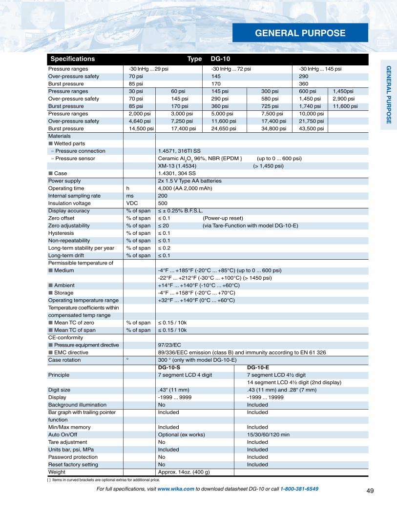
49
GEN
ERAL PURPO
SE
For full specifications, visit www.wika.com to download datasheet DG-10 or call 1-800-381-6549
Items in curved brackets are optional extras for additional price.
Specifications Type DG-10
GENERAL PURPOSE
Pressure ranges -30 InHg ... 29 psi -30 InHg ... 72 psi -30 InHg ... 145 psi Over-pressure safety 70 psi 145 290 Burst pressure 85 psi 170 360 Pressure ranges 30 psi 60 psi 145 psi 300 psi 600 psi 1,450psiOver-pressure safety 70 psi 145 psi 290 psi 580 psi 1,450 psi 2,900 psi Burst pressure 85 psi 170 psi 360 psi 725 psi 1,740 psi 11,600 psi Pressure ranges 2,000 psi 3,000 psi 5,000 psi 7,500 psi 10,000 psi Over-pressure safety 4,640 psi 7,250 psi 11,600 psi 17,400 psi 21,750 psi Burst pressure 14,500 psi 17,400 psi 24,650 psi 34,800 psi 43,500 psi Materials Wetted parts » Pressure connection 1.4571, 316TI SS » Pressure sensor Ceramic Al2O3 96%, NBR EPDM (up to 0 ... 600 psi) XM-13 (1.4534) (> 1,450 psi) Case 1.4301, 304 SSPower supply 2x 1.5 V Type AA batteries Operating time h 4,000 (AA 2,000 mAh)Internal sampling rate ms 200Insulation voltage VDC 500Display accuracy % of span ≤ ± 0.25% B.F.S.L.Zero offset % of span ≤ 0.1 (Power-up reset)Zero adjustability % of span ≤ 20 (via Tare-Function with model DG-10-E)Hysteresis % of span ≤ 0.1Non-repeatability % of span ≤ 0.1Long-term stability per year % of span ≤ 0.2Long-term drift % of span ≤ 0.1Permissible temperature of Medium -4°F ... +185°F (-20°C ... +85°C) (up to 0 ... 600 psi) -22°F ... +212°F (-30°C ... +100°C) (> 1450 psi) Ambient +14°F ... +140°F (-10°C ... +60°C) Storage -4°F ... +158°F (-20°C ... +70°C) Operating temperature range +32°F ... +140°F (0°C ... +60°C) Temperature coefficients within compensated temp range Mean TC of zero % of span ≤ 0.15 / 10k Mean TC of span % of span ≤ 0.15 / 10kCE-conformity Pressure equipment directive 97/23/EC EMC directive 89/336/EEC emission (class B) and immunity according to EN 61 326Case rotation ° 300 ° (only with model DG-10-E) DG-10-S DG-10-EPrinciple 7 segment LCD 4 digit 7 segment LCD 4½ digit 14 segment LCD 4½ digit (2nd display)Digit size .43“ (11 mm) .43 (11 mm) and .28“ (7 mm)Display -1999 ... 9999 -1999 ... 19999Background illumination No IncludedBar graph with trailing pointer Included Includedfunction Min/Max memory Included IncludedAuto On/Off Optional (ex works) 15/30/60/120 minTare adjustment No IncludedUnits bar, psi, MPa Included IncludedPassword protection No Included Reset factory setting No IncludedWeight Approx. 14oz. (400 g)

50
GEN
ERAL
PU
RPO
SE
For full specifications, visit www.wika.com to download datasheet DG-10 or call 1-800-381-6549
Electronic Pressure Catalog > General Purpose > DG-10
Dimensions in inches (mm)Ingress protection IP 65 per IEC 60529.
Pressure connections
1.81“ (45.8 mm).22“ (5.6 mm)
.62" 15.8
Ø 3.1
5" (80
mm)
Ø 3.2
8" (83
.5 mm
)
2.74"
(69
.5 mm
).59
" (15
mm)
1.08
”(27.
5mm
).7
5”
(19m
m)
1/2NPT
.85”
(21.
5mm
)
.51”
(13m
m)
1/2 NPT maleOrder code: ND
1/4 NPT maleOrder code: NB
G 1/4 maleDIN 3852-EOrder code: HD
.55“
(14m
m)
.89“
(22.
5mm
)
1.12
”(28.
5mm
)
.79”
(20m
m)
.12”
(3m
m)
.12”
(3m
m) .24”
(6mm) .69”
(17.5mm)
.85”
(21.
5mm
)
.51”
(13m
m)
.08”
(2m
m)
.08”
(2m
m) .20”
(5mm).37”
(9.5mm)
O
O
O
O
G1/2B Order code: GD
G1/4BOrder code: GB
GENERAL PURPOSE
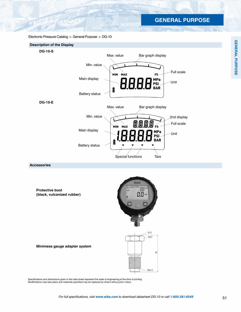
51
GEN
ERAL PURPO
SE
For full specifications, visit www.wika.com to download datasheet DG-10 or call 1-800-381-6549
Electronic Pressure Catalog > General Purpose > DG-10
Specifications and dimensions given in this data sheet represent the state of engineering at the time of printing.Modifications may take place and materials specified may be replaced by others without prior notice.
Description of the Display
DG-10-S
DG-10-E
Max. value
Min. value
Main display
Battery status
Bar graph display
Full scale
Unit
Max. value
Min. value
Main display
Battery status
Bar graph display
Full scale
Unit
Special functions Tare
2nd display
Protective boot (black, vulcanized rubber)
Accessories
Minimess gauge adapter system
GENERAL PURPOSE

52
GEN
ERAL
PU
RPO
SE
For full specifications, visit www.wika.com to download datasheet DG-10 or call 1-800-381-6549
Electronic Pressure Catalog > General Purpose > DG-10
Type DG-10 Digital Pressure Gauge
Standard Features
Case: 3.15” diameter stainless steel Process connection: 1/4” NPT male Power requirements: 2 AA batteries Enhanced version includes protective rubber boot
Description DG-10-S DG-10-E Range Standard Enhanced Part # Part #
-30 inHg…29 psi 50365444 50365657 -30 inHg…72 psi 50365452 50365673-30 inHg…145 psi 50365461 503656900 psi ... 30 psi 50365479 50365720 0 psi ...60 psi 50365487 503657710 psi ...145 psi 50365495 503657890 psi ...300 psi 50365509 503657970 psi ...600 psi 50365517 50365819 0 psi ...1,450 psi 50365525 503658270 psi ...2,000 psi 50365584 503658350 psi ...3,000 psi 50365592 503658430 psi ...5,000 psi 50365614 503658510 psi ...7,500 psi 50365622 50365860 0 psi ...10,000 psi 50365631 50365878
Type DG-10-E
Type DG-10-S
GENERAL PURPOSE
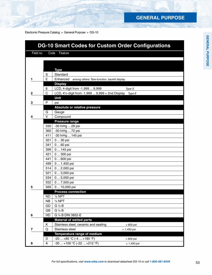
53
GEN
ERAL PURPO
SE
For full specifications, visit www.wika.com to download datasheet DG-10 or call 1-800-381-6549
Electronic Pressure Catalog > General Purpose > DG-10
GENERAL PURPOSE
DG-10 Smart Codes for Custom Order Configurations Field no. Code Feature
Type S Standard 1 E Enhanced among others: Tare-function, backlit display Display 8 LCD, 4-digit from -1,999 ... 9,999 Type S 2 C LCD, 4½-digit from -1,999 ... 9,999 + 2nd Display Type E Unit 3 P psi Absolute or relative pressure G Gauge 4 V Compound Pressure range 330 -30 InHg ... 29 psi 360 -30 InHg ... 72 psi 411 -30 InHg ... 145 psi 321 0 ... 30 psi 341 0 ... 60 psi 399 0 ... 145 psi 421 0 ... 300 psi 441 0 ... 600 psi 499 0 ... 1,450 psi 514 0 ... 2,000 psi 521 0 ... 3,000 psi 534 0 ... 5,000 psi 552 0 ... 7,500 psi 5 569 0 ... 10,000 psi Process connection ND ½ NPT NB ¼ NPT GD G ½ B GB G ¼ B 6 HD G ¼ B DIN 3852-E Material of wetted parts K Stainless steel, ceramic and sealing < 600 psi7 Q Stainless steel > 1,450 psi Temperature range of medium D -20 ... +85 °C (-4 ... +185 °F) < 600 psi8 A -30 ... +100 °C (-22 ... +212 °F) > 1,450 psi

54
GEN
ERAL
PU
RPO
SE
For full specifications, visit www.wika.com to download datasheet DG-10 or call 1-800-381-6549
Electronic Pressure Catalog > General Purpose > DG-10
GENERAL PURPOSE
1 2 3 4 5 6 7 8 9 10 11 12*DG-10 - - D 1 - - - Z Z -
*Additional order details
Order Code:
DG-10 Smart Codes for Custom Order Configurations (cont') Field no. Code Feature
Sealing Z Without 1 NBR9 B EPDM Certificates Z Without10 1 NIST certificate Protective rubber boot Z Without11 S Vulcanized rubber protective boot Additional Order Details Z Without12 T Additional text

55
GEN
ERAL PURPO
SE
For full specifications, visit www.wika.com to download datasheet PSD-30 or call 1-800-381-6549
Electronic Pressure Catalog > General Purpose > PSD-30
Type PSD-30 Pressure Transmitter with Integral LED Display and Programmable Solid State Switches
Description
Award-winning functionality and designThe design and outstanding functionality of the PSD-30 received the IF Product Design Award in 2009. The display, with its .35“ ( 9 mm) high digits, was designed to be as large as possible and positioned at an angle, so the pressure reading is visible from a distance of at least 10 feet (3 meters). Time-proven and rugged LED technology with 14-segment display is used so alphanumeric messages are much easier to under-stand compared to typical 7-segment displays.
The large, ergonomically designed programming push buttons provide the user with tactile feedback for immediate confirmation that the touch event was registered by the trans-mitter. The user-friendly menu navigation layout meets the new VDMA Standard form for fluid sensors (24574-1, Part 1, pressure switch). The goal of the VDMA is to simplify the use of pressure switches by standardizing menu navigation and display parameters.
Flexible and adaptableThe PSD-30 can be adjusted three different ways to fit specific installation requirements. The display and electrical connection can be rotated independently to maximize visibility while still orienting the electrical connection in the best position for the cable connector. If the transmitter is installed overhead or upside down the display can be electronically rotated 180°.
Quality and reliabilityTime tested, proven WIKA thin film and piezoresitive pressure sensor technology is an integral part of the PSD-30 providing the high quality and long term reliability users demand.
Applications
Pumps and compressors Hydraulics and pneumatics Machine tools Machine building
Special Features
Available with single or dual NPN or PNP solid state switches High visibility, rugged 14-segment red LED display electronically rotates 180° for top-down installation Independent rotation between the M12x1 electrical connection and the display User-friendly, intuitive 3-key operation Versions with 4-20 mA or 0-10V analog output available Programming menu meets VDMA Standards for user friendly navigation
Type PSD-30 Pressure Transmitter with Integral LED Display
GENERAL PURPOSE
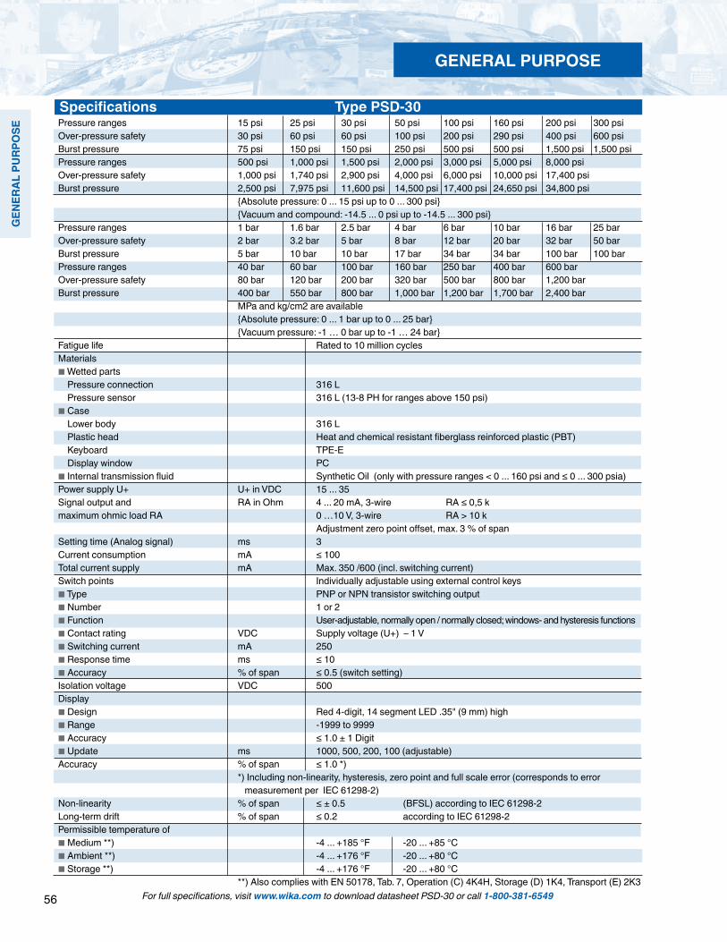
56
GEN
ERAL
PU
RPO
SE
For full specifications, visit www.wika.com to download datasheet PSD-30 or call 1-800-381-6549
GENERAL PURPOSE
Pressure ranges 15 psi 25 psi 30 psi 50 psi 100 psi 160 psi 200 psi 300 psi Over-pressure safety 30 psi 60 psi 60 psi 100 psi 200 psi 290 psi 400 psi 600 psi Burst pressure 75 psi 150 psi 150 psi 250 psi 500 psi 500 psi 1,500 psi 1,500 psi Pressure ranges 500 psi 1,000 psi 1,500 psi 2,000 psi 3,000 psi 5,000 psi 8,000 psi Over-pressure safety 1,000 psi 1,740 psi 2,900 psi 4,000 psi 6,000 psi 10,000 psi 17,400 psi Burst pressure 2,500 psi 7,975 psi 11,600 psi 14,500 psi 17,400 psi 24,650 psi 34,800 psi Absolute pressure: 0 ... 15 psi up to 0 ... 300 psi Vacuum and compound: -14.5 ... 0 psi up to -14.5 ... 300 psi Pressure ranges 1 bar 1.6 bar 2.5 bar 4 bar 6 bar 10 bar 16 bar 25 bar Over-pressure safety 2 bar 3.2 bar 5 bar 8 bar 12 bar 20 bar 32 bar 50 bar Burst pressure 5 bar 10 bar 10 bar 17 bar 34 bar 34 bar 100 bar 100 bar Pressure ranges 40 bar 60 bar 100 bar 160 bar 250 bar 400 bar 600 bar Over-pressure safety 80 bar 120 bar 200 bar 320 bar 500 bar 800 bar 1,200 bar Burst pressure 400 bar 550 bar 800 bar 1,000 bar 1,200 bar 1,700 bar 2,400 bar MPa and kg/cm2 are available Absolute pressure: 0 ... 1 bar up to 0 ... 25 bar Vacuum pressure: -1 … 0 bar up to -1 … 24 barFatigue life Rated to 10 million cyclesMaterials Wetted parts Pressure connection 316 L Pressure sensor 316 L (13-8 PH for ranges above 150 psi) Case Lower body 316 L Plastic head Heat and chemical resistant fiberglass reinforced plastic (PBT) Keyboard TPE-E Display window PC Internal transmission fluid Synthetic Oil (only with pressure ranges < 0 ... 160 psi and ≤ 0 ... 300 psia)Power supply U+ U+ in VDC 15 ... 35Signal output and RA in Ohm 4 ... 20 mA, 3-wire RA ≤ 0,5 kmaximum ohmic load RA 0 …10 V, 3-wire RA > 10 k Adjustment zero point offset, max. 3 % of spanSetting time (Analog signal) ms 3Current consumption mA ≤ 100Total current supply mA Max. 350 /600 (incl. switching current)Switch points Individually adjustable using external control keys Type PNP or NPN transistor switching output Number 1 or 2 Function User-adjustable, normally open / normally closed; windows- and hysteresis functions Contact rating VDC Supply voltage (U+) – 1 V Switching current mA 250 Response time ms ≤ 10 Accuracy % of span ≤ 0.5 (switch setting)Isolation voltage VDC 500Display Design Red 4-digit, 14 segment LED .35" (9 mm) high Range -1999 to 9999 Accuracy ≤ 1.0 ± 1 Digit Update ms 1000, 500, 200, 100 (adjustable)Accuracy % of span ≤ 1.0 *) *) Including non-linearity, hysteresis, zero point and full scale error (corresponds to error measurement per IEC 61298-2)Non-linearity % of span ≤ ± 0.5 (BFSL) according to IEC 61298-2Long-term drift % of span ≤ 0.2 according to IEC 61298-2Permissible temperature of Medium **) -4 ... +185 °F -20 ... +85 °C Ambient **) -4 ... +176 °F -20 ... +80 °C Storage **) -4 ... +176 °F -20 ... +80 °C **) Also complies with EN 50178, Tab. 7, Operation (C) 4K4H, Storage (D) 1K4, Transport (E) 2K3
Specifications Type PSD-30
Specifications Type PSD-30

57
GEN
ERAL PURPO
SE
Circular connector *M 12x1 5-pinOrder Code: M5
1/4" NPT Male(others available)Order Code: NB
Optional pressure connections (others available)
Electrical connection
G 1/4 FemaleOrder Code: TB
G 1/4 A to DIN 3852-E
Order Code: HD
* Mating connectors are not included
Pressure connections
G 1/2 BOrder Code: GD
Dimensions in inches (mm)
Rated temperature range +32 ... +176 °F 0 ... +80 °C Temperature error within rated temperature range ≤ 1.0 typ., ≤ 2.5 max.Temperature coefficients within rated temperature range Mean TC of zero % of span ≤ 0.2 / 10 K Mean TC of span % of span ≤ 0.2 / 10 KRelative humidity % < 90Approval cULusRoHS-conformity YesCE-conformity Pressure equipment directive This instrument is a pressure accessory as defined by the directive 97/23/EC EMC directive 2004/108/EEC, EN 61 326 Emission (Group 1, Class B) and Immunity (industrial locations)Shock resistance g 50 according to IEC 60068-2-27 (mechanical shock)Vibration resistance g 10 according to IEC 60068-2-6 (vibration under resonance)Wiring protection Overvoltage protection VDC 40 Short-circuit protection S+/SP1/SP2 to U- Reverse polarity protection U+ to U-Weight oz Approx. 7
Specifications Type PSD-30
For full specifications, visit www.wika.com to download datasheet PSD-30 or call 1-800-381-6549
Electronic Pressure Catalog > General Purpose > PSD-30
GENERAL PURPOSE
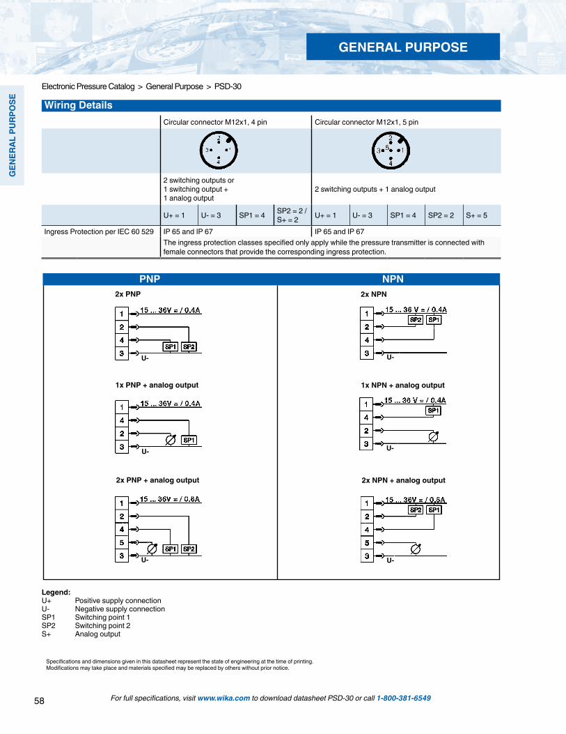
58
GEN
ERAL
PU
RPO
SE
Specifications and dimensions given in this datasheet represent the state of engineering at the time of printing.Modifications may take place and materials specified may be replaced by others without prior notice.
2x PNP 2x NPN
1x PNP + analog output 1x NPN + analog output
2x PNP + analog output 2x NPN + analog output
Wiring DetailsCircular connector M12x1, 4 pin Circular connector M12x1, 5 pin
2 switching outputs or 1 switching output + 1 analog output
2 switching outputs + 1 analog output
U+ = 1 U- = 3 SP1 = 4 SP2 = 2 /S+ = 2 U+ = 1 U- = 3 SP1 = 4 SP2 = 2 S+ = 5
Ingress Protection per IEC 60 529 IP 65 and IP 67 IP 65 and IP 67The ingress protection classes specified only apply while the pressure transmitter is connected with female connectors that provide the corresponding ingress protection.
Legend:U+ Positive supply connectionU- Negative supply connectionSP1 Switching point 1SP2 Switching point 2S+ Analog output
PNP NPN
U- U-
U- U-
U- U-
GENERAL PURPOSE
For full specifications, visit www.wika.com to download datasheet PSD-30 or call 1-800-381-6549
Electronic Pressure Catalog > General Purpose > PSD-30

59
GEN
ERAL PURPO
SE
For full specifications, visit www.wika.com to download datasheet PSD-30 or call 1-800-381-6549
Electronic Pressure Catalog > General Purpose > PSD-30
GENERAL PURPOSE
PSD-30 Smart Codes for Custom Order Configurations Field no. Code Feature
Signal output Q Dual PNP switch output + 4…20mA R Dual PNP switch output + 0…10V V Dual NPN switch output + 4…20mA1 ? Other Unit P PSI (Selectable BAR/PSI/MPA/KPA/KG/cm2)2 ? Other Pressure reference G Gauge A Absolute3 V Compound Pressure range 310 -14.5 psi…0 320 -14.5 psi…15 psi 351 -14.5 psi…60 psi 379 -14.5 psi…100 psi 415 -14.5 psi…200 psi 422 -14.5 psi…300 psi 310 0…15 psi 0…15 psia 317 0...25 psi 0...25 psia 321 0…30 psi 0…30 psia 335 0…50 psi 0…50 psia 369 0…100 psi 0…100 psia 411 0…160 psi 0…160 psia 414 0...200 psi 0...200 psia 421 0…300 psi 0…300 psia 434 0…500 psi 469 0…1,000 psi 514 0…2,000 psi 521 0…3,000 psi 534 0…5,000 psi 555 0…8,000 psi 4 ??? Other Process connection NB 1/4" NPT HD G 1/4 A DIN 3852-E TB G 1/4 female 5 ?? Other Process seal ring (not required for NPT) C Copper S Stainless steel Z Without 6 ? Other
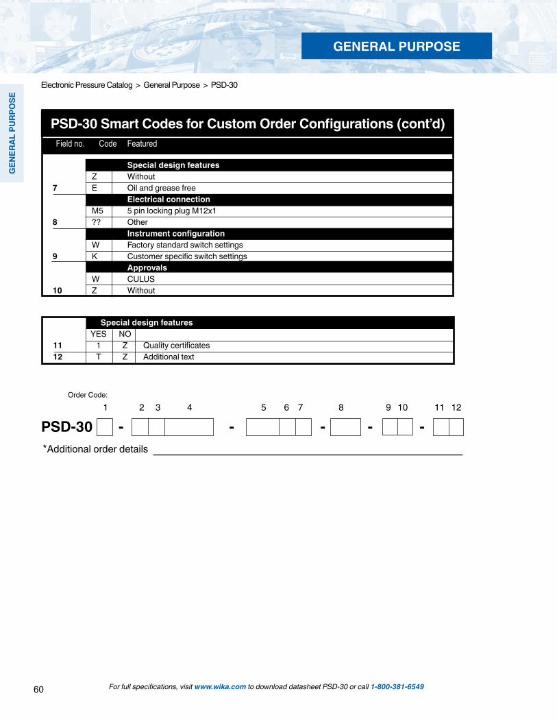
60
GEN
ERAL
PU
RPO
SE
For full specifications, visit www.wika.com to download datasheet PSD-30 or call 1-800-381-6549
Electronic Pressure Catalog > General Purpose > PSD-30
GENERAL PURPOSE
PSD-30 Smart Codes for Custom Order Configurations (cont’d) Field no. Code Featured
Special design features Z Without7 E Oil and grease free Electrical connection M5 5 pin locking plug M12x18 ?? Other Instrument configuration W Factory standard switch settings9 K Customer specific switch settings Approvals W CULUS10 Z Without
Special design features YES NO11 1 Z Quality certificates12 T Z Additional text
1 2 3 4 5 6 7 8 9 10 11 12
PSD-30 - - - - - *Additional order details
Order Code:

61
GEN
ERAL PURPO
SE
For full specifications, visit www.wika.com to download datasheet TSD-30 or call 1-800-381-6549
Electronic Pressure Catalog > General Purpose > TSD-30
Type TSD-30 Temperature Switch with Integral LED Display
TSD-30 Temperature Switch
Applications
Machine tools Hydraulics Coolant and lubrication systems Machine building
Special Features
Available with single or dual NPN or PNP solid state user-programmable switches High visibility, rugged 14-segment red LED display elec- tronically rotates 180° for top-down or horizontal installation Independent rotation between the M12x1 electrical connection and the display to optimize installation position User-friendly, intuitive 3-key operation Versions with 4-20 mA or 0-10V analog output available Programming menu meets VDMA Standards for user friendly navigation
Description
Award-winning in design and functionalityThe design and outstanding functionality of the PSD-30 pressure switch received the IF Product Design Award in 2009. The TSD-30 temperature switch uses a similar design and functionality. The display, with its .35” ( 9 mm) high digits, was designed to be as large as possible and positioned at an angle, so the temperature reading is visible from a distance of at least 10 feet (3 meters). Rugged LED technology with a 14-segment display is used so alphanumeric messages are much easier to understand when compared to typical 7-segment displays.
The large, ergonomically designed programming push buttonsprovide the user with tactile feedback for immediate confirmation that the touch event was registered by the switch. The user-friendly menu navigation layout meets the
VDMA standard for fluid sensors (24574-2, part 2, tempera-ture switches). The goal of the VDMA is to simplify the use of switches by standardizing menu navigation and display parameters. Flexible and adaptableThe TSD-30 can be adjusted three different ways to fit specificinstallation requirements. The display and electrical connec-tion can be rotated independently to maximize visibility while still orienting the electrical connection in the best position for the cable connector. The display can be electronically rotated 180° if needed for specific installation requirements.
Quality and reliability Time tested, proven WIKA technology is an integral part of the TSD-30 providing the high quality and long-term reliability users demand.
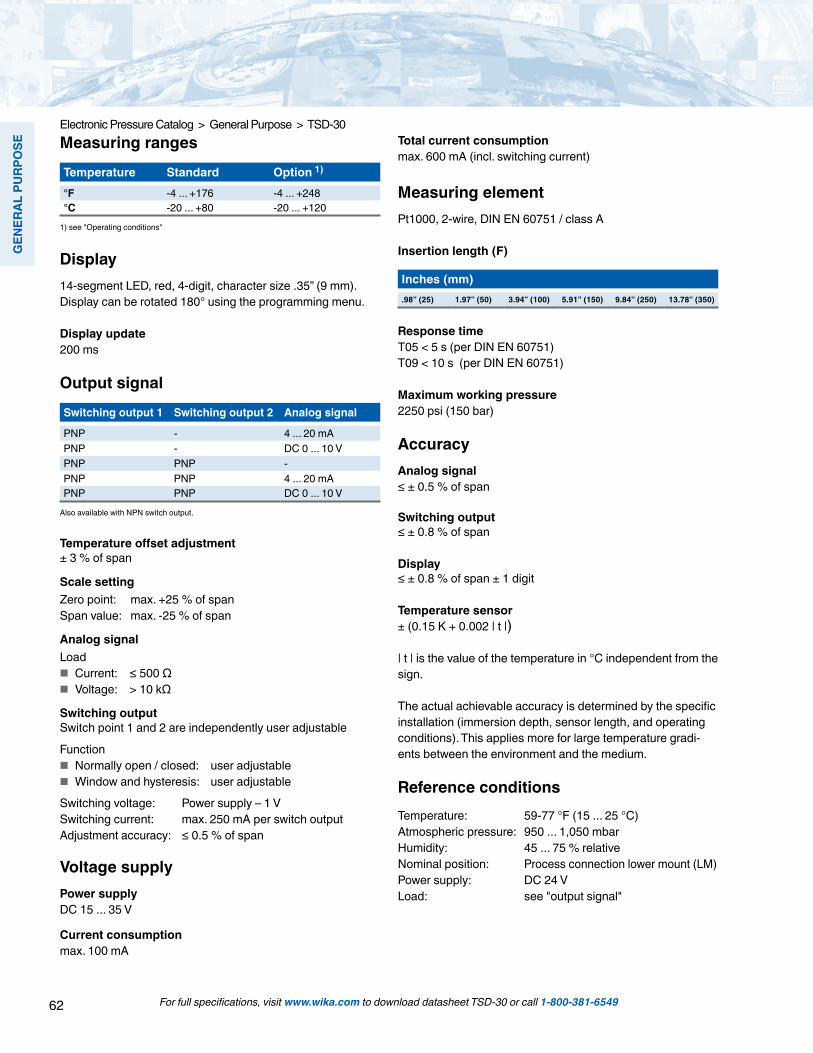
62
GEN
ERAL
PU
RPO
SE
For full specifications, visit www.wika.com to download datasheet TSD-30 or call 1-800-381-6549
Electronic Pressure Catalog > General Purpose > TSD-30Measuring rangesTemperature Standard Option 1)
°F -4 ... +176 -4 ... +248°C -20 ... +80 -20 ... +120
1) see "Operating conditions"
Display14-segment LED, red, 4-digit, character size .35” (9 mm).Display can be rotated 180° using the programming menu.
Display update200 ms
Output signalSwitching output 1 Switching output 2 Analog signal
PNP - 4 ... 20 mAPNP - DC 0 ... 10 VPNP PNP -PNP PNP 4 ... 20 mAPNP PNP DC 0 ... 10 V
Also available with NPN switch output.
Temperature offset adjustment± 3 % of span
Scale settingZero point: max. +25 % of spanSpan value: max. -25 % of span
Analog signalLoad
Current: ≤ 500 Ω Voltage: > 10 kΩ
Switching outputSwitch point 1 and 2 are independently user adjustable
Function Normally open / closed: user adjustable Window and hysteresis: user adjustable
Switching voltage: Power supply – 1 VSwitching current: max. 250 mA per switch outputAdjustment accuracy: ≤ 0.5 % of span
Voltage supplyPower supplyDC 15 ... 35 V
Current consumptionmax. 100 mA
Total current consumptionmax. 600 mA (incl. switching current)
Measuring elementPt1000, 2-wire, DIN EN 60751 / class A
Insertion length (F)
Inches (mm).98” (25) 1.97” (50) 3.94” (100) 5.91” (150) 9.84” (250) 13.78” (350)
Response timeT05 < 5 s (per DIN EN 60751)T09 < 10 s (per DIN EN 60751)
Maximum working pressure2250 psi (150 bar)
AccuracyAnalog signal≤ ± 0.5 % of span
Switching output≤ ± 0.8 % of span
Display≤ ± 0.8 % of span ± 1 digit
Temperature sensor± (0.15 K + 0.002 | t |)
| t | is the value of the temperature in °C independent from the sign.
The actual achievable accuracy is determined by the specific installation (immersion depth, sensor length, and operating conditions). This applies more for large temperature gradi-ents between the environment and the medium.
Reference conditionsTemperature: 59-77 °F (15 ... 25 °C)Atmospheric pressure: 950 ... 1,050 mbarHumidity: 45 ... 75 % relativeNominal position: Process connection lower mount (LM)Power supply: DC 24 VLoad: see "output signal"

63
GEN
ERAL PURPO
SE
For full specifications, visit www.wika.com to download datasheet TSD-30 or call 1-800-381-6549
Electronic Pressure Catalog > General Purpose > TSD-30
Circular connector M12 x 1, 4-pin
AssignmentU+ U- S+ SP1 SP21 3 2 4 2
Circular connector M12 x 1, 5-pin
AssignmentU+ U- S+ SP1 SP21 3 5 4 2
Operating conditionsTemperatures and humidityMedium temperature: -4 ... +176 °F (-20 ... +80 °C)Ambient temperature: -4 ... +176 °F (-20 ... +80 °C)Storage temperature: -4 ... +176 °F (-20 ... +80 °C)Permissible humidity: 45 ... 75 % relative
Installation instructionsMounting position: as required
At high medium or ambient temperatures, take steps to make sure that the instrument case temperature does not exceed 176 °F (80 °C) in continuous operation (the temperature is measured at the hex of the process connection).
The thread must not be immersed into medium at tempera-tures above 176 °F (80 °C)
Process connectionsConnections
Standard ThreadANSI / ASME B1.20.1 1/4 NPT 1/2 NPTDIN 3852-E G 1/4 A G 1/2 A
Other connections available – contact factoryDetails on the sensor dimensions see “Dimensions in mm”.
Sealing
for connections per DIN 3852-EStandard withoutOption NBR, FPM / FKM
MaterialsWetted partsTemperature sensor: 316Ti SS
Non-wetted partsCase: 304 SSKeyboard: TPE-EDisplay window: PCDisplay head: PC+ABS-Blend
Approvals, directives and certificatesCE conformityEMC directive 2004/108/EC, EN 61326-2-3 emission (group 1, class B) and interference immunity (industrial applications)
RoHS conformityYes
Connection diagram
Legend:U+ Positive supply voltageU- Reference potentialSP1 Switching output 1SP2 Switching output 2S+ Analog output
Electrical connectionsConnectionsCircular connector M12 x 1, 4-pinCircular connector M12 x 1, 5-pin 1)
1) Only for version with SP1, SP2 and S+
Ingress protectionIP 65 and IP 67The stated ingress protection (per IEC 60529) only applies when installed using mating connectors that have the appropriate ingress protection.
Electrical safetyShort-circuit resistance: S+ / SP1 / SP2 vs. UReverse polarity protection: U+ vs. UInsulation voltage: DC 500 VOvervoltage protection: DC 40 V

64
GEN
ERAL
PU
RPO
SE
For full specifications, visit www.wika.com to download datasheet TSD-30 or call 1-800-381-6549
Electronic Pressure Catalog > General Purpose > TSD-30
Parallel thread Tapered thread
with M12 x 1 circular connector4-pin / 5-pin
G1 L1G 1/4 A DIN 3852-E 12G 1/2 A DIN 3852-E 14
G1 L11/4 NPT 131/2 NPT 19
Dimensions in mm (1 inch = 25.4 mm)Temperature switch
Weight: approx. 10.6 oz (0.3 kg)
Insertion length
Process connections
Seals Order no.NBR profile sealing G 1/4 A DIN 3852-E 1537857FPM/FKM profile sealing G 1/4 A DIN 3852-E 1576534NBR profile sealing G 1/2 A DIN 3852-E 1039067FPM/FKM profile sealing G 1/2 A DIN 3852-E 1039075
F25 50 100 150 250 350
Accessories and spare partsCompression fittings Order no.G 1/4 A, ferrule from stainless steel 3199101G 1/2 A, ferrule from stainless steel 32215551/4 NPT, ferrule from stainless steel 32329051/2 NPT, ferrule from stainless steel 3320710
When using a compression fitting, a limited pressure strength applies.

65
GEN
ERAL PURPO
SE
For full specifications, visit www.wika.com to download datasheet TSD-30 or call 1-800-381-6549
Electronic Pressure Catalog > General Purpose > TSD-30
TSD-30 Smart Codes for Custom Order Configurations Field no. Code Feature
Signal output Q Dual PNP switch output + 4…20mA R Dual PNP switch output + 0…10V V Dual NPN switch output + 4…20mA 1 ? Other Unit F Degrees OF (user selectable for OC) 2 ? Other Temperature range A -4 ... +176 OF (user selectable for OC) 3 ? Other Probe length 0025 0.98" / 25 mm 0050 1.97" / 50 mm 0100 3.94" / 100 mm 0150 5.91" / 150 mm 0250 9.84" / 250 mm 0300 13.78" / 350 mm 4 ???? Other Process connection ND 1/2" NPT NB 1/4" NPT GT G 1/2 A DIN 3852-E 5 ?? Other Process seal ring (not required for NPT) Z Without 1 NBR L FPM / FKM 6 ? Other Electrical connection M5 5 pin locking plug M12x1 (NEMA 5 / IP65) 7 ?? Other
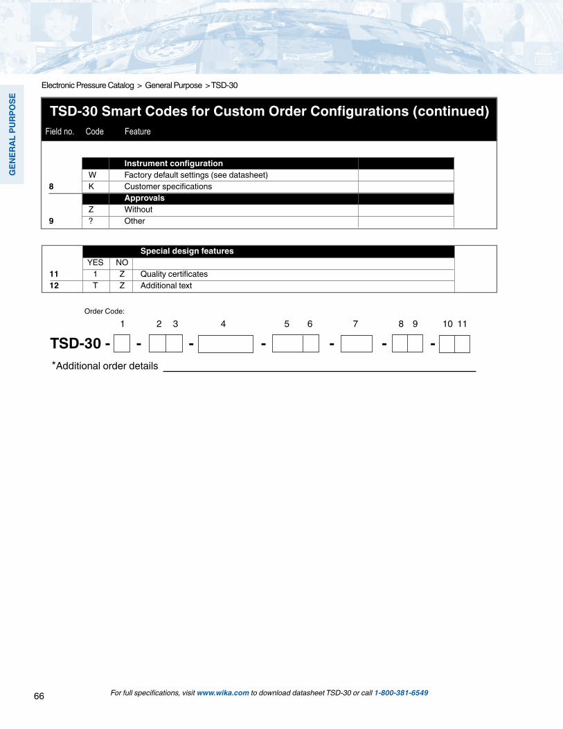
66
GEN
ERAL
PU
RPO
SE
For full specifications, visit www.wika.com to download datasheet TSD-30 or call 1-800-381-6549
Electronic Pressure Catalog > General Purpose > TSD-30
1 2 3 4 5 6 7 8 9 10 11
TSD-30 - - - - - - - *Additional order details
Order Code:
Special design features YES NO11 1 Z Quality certificates12 T Z Additional text
TSD-30 Smart Codes for Custom Order Configurations (continued) Field no. Code Feature
Instrument configuration W Factory default settings (see datasheet) 8 K Customer specifications Approvals Z Without 9 ? Other
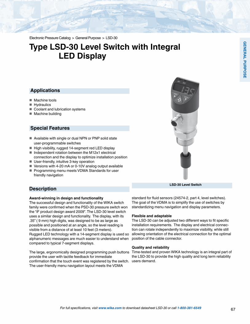
67
GEN
ERAL PURPO
SE
For full specifications, visit www.wika.com to download datasheet LSD-30 or call 1-800-381-6549
Electronic Pressure Catalog > General Purpose > LSD-30
Type LSD-30 Level Switch with Integral LED Display
LSD-30 Level Switch
Applications
Machine tools Hydraulics Coolant and lubrication systems Machine building
Special Features
Available with single or dual NPN or PNP solid state user-programmable switches High visibility, rugged 14-segment red LED display Independent rotation between the M12x1 electrical connection and the display to optimize installation position User-friendly, intuitive 3-key operation Versions with 4-20 mA or 0-10V analog output available Programming menu meets VDMA Standards for user friendly navigation
Description
Award-winning in design and functionalityThe successful design and functionality of the WIKA switch family were confirmed when the PSD-30 pressure switch won the “iF product design award 2009”. The LSD-30 level switch uses a similar design and functionality. The display, with its .35” ( 9 mm) high digits, was designed to be as large as possible and positioned at an angle, so the level reading is visible from a distance of at least 10 feet (3 meters). Rugged LED technology with a 14-segment display is used so alphanumeric messages are much easier to understand when compared to typical 7-segment displays.
The large, ergonomically designed programming push buttonsprovide the user with tactile feedback for immediate confirmation that the touch event was registered by the switch. The user-friendly menu navigation layout meets the VDMA
standard for fluid sensors (24574-2, part 4, level switches). The goal of the VDMA is to simplify the use of switches by standardizing menu navigation and display parameters. Flexible and adaptableThe LSD-30 can be adjusted two different ways to fit specificinstallation requirements. The display and electrical connec-tion can rotate independently to maximize visibility, while still allowing orientation of the electrical connection for the optimal position of the cable connector.
Quality and reliability Time-tested and proven WIKA technology is an integral part of the LSD-30 to provide the high quality and long term reliability users demand.

68
GEN
ERAL
PU
RPO
SE
For full specifications, visit www.wika.com to download datasheet LSD-30 or call 1-800-381-6549
Measuring rangesfor parallel process connectionsSensor length F 250 370 410 520 730mm 189 309 349 459 669inch 7.44 12.17 13.74 18.07 26.34
for tapered process connectionsSensor length F 250 370 410 520 730mm 205 325 365 475 684inch 8.07 12.80 14.37 18.70 26.93
For insertion lengths, see "Dimensions in mm" on page 4
Specific gravity range of the medium≥ 0,7 g/cm3
Display14-segment LED, red, 4-digit, .35” (9 mm) character height Display can be turned 180° electronically via program steps.
Update200 ms
Output signalSwitching output 1 Switching output 2 Analog signal
PNP - 4 ... 20 mAPNP - DC 0 ... 10 VPNP PNP -PNP PNP 4 ... 20 mAPNP PNP DC 0 ... 10 V
Alternatively also available with NPN rather than PNP switching output
Offset adjustment (display)max. + 59” / 1.5 meters
Scaling (display and analog signal)Zero point: max. +25 % of spanFinal value: max. -25 % of span
Analog signalLoad
Current output: ≤ 500 Ω Voltage output: > 10 kΩ
Switching outputSwitch point 1 and 2 are individually adjustable
Function Normally open and normally closed: user adjustable Window and hysteresis: user adjustable
Switching voltage: Power supply – 1 VSwitching current: max. 250 mA per switching outputResponse time: < 200 msAdjustment accuracy: 0.1” (2.5 mm) to step change
Voltage supplyPower supplyDC 15 ... 35 V
Current consumptionmax. 100 mA
Total current consumptionmax. 600 mA (incl. switching current)
Measuring elementResistance measuring chain with reed switches and float
Resolution< .24” (6 mm)
Response time< 700 ms
Maximum working pressure43.5 psi (3 bar)
Media compatibilityTest following ISO 7620, section 6, table 1
Medium StandardMineral oil HLP per DIN 51524Aqueous solution HFC per VDMA 24317Organic ester HFD-U per VDMA 24317Triglyceride (rape oil) HETG per VDMA 24568Synthetic ester HEES per VDMA 24568Polyglycols HEPG per VDMA 24568
Accuracy (electronics)Switching and indication accuracy at room temperature1 % of span (display ±1 digit)
Analog signal≤ ± 0.5 % of span

69
GEN
ERAL PURPO
SE
For full specifications, visit www.wika.com to download datasheet LSD-30 or call 1-800-381-6549
Circular connector M12 x 1, 4-pin
AssignmentU+ U- S+ SP1 SP21 3 2 4 2
Circular connector M12 x 1, 5-pin
AssignmentU+ U- S+ SP1 SP21 3 5 4 2
Legend:U+ Positive supply voltageU- Reference potentialSP1 Switching output 1SP2 Switching output 2S+ Analogue output
Reference conditionsTemperature: 50 ... 77 °F (15 ... 25 °C)Atmospheric pressure: 950 ... 1,050 mbar
Humidity: 45 ... 75 % relativeInstalled position: Process connection lower mount (LM)Power supply: DC 24 VLoad: see "Output signal"
Operating conditionsTemperatures and humidity ratings
Media: -4 … 176 °F (-20 ... +80 °C)
Ambient: -4 … 176 °F (-20 ... +80 °C)
Storage: -4 … 176 °F (-20 ... +80 °C)
Permissible humidity: 45 ... 75 % relative
InstallationMounting position: vertical
Process connectionsConnections
Standard ThreadDIN 3852-E G ¾ AANSI / ASME B1.20.1 ¾ NPT
Other connections on request.Details on the sensor dimensions see "Dimensions in mm".
Sealing
for connections per DIN 3852-EStandard withoutOption NBR, FPM / FKM
MaterialsWetted partsLevel sensor: 316Ti SSFloat: see “Media compatibility”
Non-wetted partsCase: 304 SSKeyboard TPE-EDisplay window: PCDisplay head: PC+ABS-Blend
Connection diagram
Approvals, directives and certificatesCE conformityEMC directive 2004/108/EC, EN 61326-2-3 emission (group 1, class B) and interference immunity (industrial application)
RoHS conformityYes
Electrical connectionsConnectionsCircular connector M12 x 1, 4-pinCircular connector M12 x 1, 5-pin 1)
1) Only for version with SP1, SP2 and S+
Ingress protectionIP 65 and IP 67The stated ingress protection (per IEC 60529) only applies when plugged in using mating connectors that have the appropriate ingress protection.
Electrical safetyShort-circuit resistance: S+ / SP1 / SP2 vs. U-Reverse polarity protection: U+ vs. U-Insulation voltage: DC 500 VOvervoltage protection: DC 40 V

70
GEN
ERAL
PU
RPO
SE
Dimensions in mm (1 mm = 0.039”)Level switch
Process connections
For full specifications, visit www.wika.com to download datasheet LSD-30 or call 1-800-381-6549
Electronic Pressure Catalog > General Purpose > LSD-30
with M12 x 1 circular connector4-pin / 5-pin
G1 L1G ¾ A DIN 3852-E 16
Parallel thread
F M250 189370 309410 349520 459730 669
Tapered thread
F M250 205370 325410 365520 475730 684
G1 L1¾ NPT 20
Weight: approx. 0.3 kg
Insertion lengths
Ordering informationModel / Sensor length F / Output signal / Process connection / Sealing
Accessories and spare partsSealings Order no.NBR profile sealing G 3/4 DIN 3852-E 1100378FPM / FKM profile sealing G 3/4 DIN 3852-E 1158309

71
GEN
ERAL PURPO
SE
For full specifications, visit www.wika.com to download datasheet LSD-30 or call 1-800-381-6549
Electronic Pressure Catalog > General Purpose > LSD-30
1 2 3 4 5 6 7 8 9 10
LSD-30 - - - - - - - *Additional order details
Order Code:
LSD-30 Smart Codes for Custom Order Configurations Field no. Code Feature
Quality certificates YES NO9 1 Z Quality certificates10 T Z Additional text
Signal output Q Dual PNP switch output + 4…20mA R Dual PNP switch output + 0…10V V Dual NPN switch output + 4…20mA 1 ? Other Display unit I Inch (user selectable for mm, cm, %) 2 ? Other Probe length 0250 250 mm / 9.84" 0370 370 mm / 14.57" 0410 410 mm / 16.14" 0520 520 mm / 20.47" 0730 730 mm / 27.74" 3 ???? Other Process connection NE 3/4" NPT NH G 3/4 A DIN 3852-E 4 ?? Other Process seal ring (not required for NPT) Z Without (always with NPT) 1 NBR L FPM / FKM 5 ? Other Electrical connection M5 5 pin locking plug M12x1 (NEMA 4 / IP67) 6 ?? Other Instrument configuration W Factory default settings (see datasheet) 7 K Customer specifications Approvals Z Without 8 ? Other
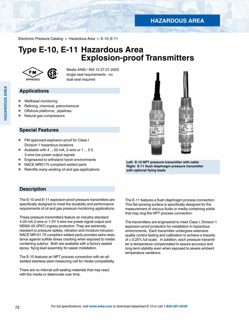
72
HAZ
ARD
OU
S AR
EA
HAZARDOUS AREA
For full specifications, visit www.wika.com to download datasheet E-10 or call 1-800-381-6549
Applications
Wellhead monitoring Refining, chemical, petrochemical Offshore platforms, pipelines Natural gas compressors
Special Features
FM-approved explosion-proof for Class I Division 1 hazardous locations Available with 4 ... 20 mA, 2-wire or 1 ... 5 V, 3-wire low power output signals Engineered to withstand harsh environments NACE MR0175 compliant wetted parts Retrofits many existing oil and gas applications
Left: E-10 NPT pressure transmitter with cableRight: E-11 flush diaphragm pressure transmitter with optional flying leads
Electronic Pressure Catalog > Hazardous Area > E-10, E-11
Type E-10, E-11 Hazardous Area Explosion-proof Transmitters
Meets ANSI / ISA 12.27.01-2003 single seal requirements - no dual seal required
Description
The E-10 and E-11 explosion-proof pressure transmitters are specifically designed to meet the durability and performance requirements of oil and gas pressure monitoring applications.
These pressure transmitters feature an industry standard 4-20 mA 2-wire or 1-5V 3-wire low power signal output and NEMA 4X (IP67) ingress protection. They are extremely resistant to pressure spikes, vibration and moisture intrusion. NACE MR-01-75 compliant wetted parts provides extra resis-tance against sulfide stress cracking when exposed to media containing sulphur. Both are available with a factory sealed epoxy flying lead assembly for easier installation.
The E-10 features an NPT process connection with an all-welded stainless steel measuring cell for media compatibility.
There are no internal soft sealing materials that may react with the media or deteriorate over time.
The E-11 features a flush diaphragm process connection. This flat sensing surface is specifically designed for the measurement of viscous fluids or media containing solids that may clog the NPT process connection.
The transmitters are engineered to meet Class I, Division 1 explosion-proof protection for installation in hazardous environments. Each transmitter undergoes extensive quality control testing and calibration to achieve a linearity of < 0.25% full scale. In addition, each pressure transmit-ter is temperature compensated to assure accuracy and long-term stability even when exposed to severe ambient temperature variations.

73
HAZARD
OU
S AREA
Specifications Type E-10, E-11
Pressure range 5 psi 10 psi 15 psi 25 psi 30 psi 60 psi 100 psi 200 psi 300 psiMaximum pressure* 29 psi 58 psi 72 psi 145 psi 145 psi 240 psi 500 psi 1,160 psi 1,160 psiBurst pressure** 35 psi 69 psi 87 psi 170 psi 170 psi 290 psi 600 psi 1,390 psi 1,390 psiPressure range 500 psi 1,000 psi 1,500 psi 2,000 psi 3,000 psi 5,000 psi 8,000 psi1 10,000 psi1 15,000 psi1Maximum pressure* 1,160 psi 1,740 psi 2,900 psi 4,600 psi 7,200 psi 11,600 psi 17,400 psi 17,400 psi 21,750 psiBurst pressure** 5,800 psi 7,970 psi 11,600 psi 14,500 psi 17,400psi 24,650 psi2 34,800 psi 34,800 psi 43,500 psiVacuum, gauge pressure, compound ranges and absolute pressure ranges are availableMaterials Wetted parts Nace compliant 4
type E-10 Stainless steel (> 300 psi stainless steel and Elgiloy) type E-11 Stainless steel O-ring: NBR Viton® Case Stainless steel Internal transmission fluid Synthetic oil (only for pressure ranges up to 300 psi or flush diaphragm units)Power supply UB DC V 10 < UB < 30 for 4 ... 20 mA, 2-wire
6 < UB < 30 for 1 ... 5 V, 3 wire low power versionSignal output and 4 ... 20 mA, 2-wire RA ≤ (UB - 10 V) / 0.02 A with RA in Ohm and UB in Voltmaximum load RA 1 ... 5 V, 3-wire RA > 10 kOhmResponse time (10 ... 90 %) ms ≤ 1 (≤ 10 ms when media temperatures are below –22 ° F ( -30 °C) for pressure
ranges up to 300 psi or with flush diaphragm)Accuracy 3) % of span ≤ 0.25 (BFSL)
% of span ≤ 0.5 (limit point calibration)Hysteresis % of span ≤ 0.1Non-repeatability % of span ≤ 0.11-year stability % of span ≤ 0.2 (at reference conditions)Permissible temperature of Medium -22 ... +212 °F -40 ... +221 °F -30 ... +100 °C -40 ... +105 °C Ambient -22 ... +212 °F -40 ... +221 °F -30 ... +100 °C -40 ... +105 °C Storage -40 ... +221 °F -58 ... +221 °F -40 ... +105 °C -50 ... +105 °C
Compensated temp. range 32 ... +176 °F 0 ... +80 °CTemperature coefficients incompensated temp range Mean TC of zero % of span < 0.2 / 10 K (< 0.4 for pressure range < 100 InWC)
Mean TC of range % of span < 0.2 / 10 KEMI specifications 89/336/EWG interference emission and immunity see EN 61 326Approval authority Factory mutual (FM / CSA) explosion-proof for:
Class I, Division 1, Groups A, B, C and D Dust ignition-proof for: Class II / III, Division 1, Groups E, F and G FM Standards according to class number 3600, 3615 and 3810
HF-immunity V/m 10 Burst KV 4Shock resistance g 1,000 according to IEC 60068-2-27 (mechanical shock)Vibration resistance g 20 according to IEC 60068-2-6 (vibration under resonance)Wiring protection Protected against reverse polarity, over voltage and short circuitingIngress protection NEMA 4X / IP 67Weight lb Approximately 0.4
* Pressure applied up to the maximum rating will cause no permanent change in specifications but may lead to zero and span shifts**Exceeding the burst pressure may result in destruction of the transmitter
1) Only Type E-10.2) For Type E-11: the burst pressure is limited to 21,000 psi unless the pressure seal is accomplished by using the sealing ring underneath the hex.3) Includes non-linearity, hysteresis and repeatability. Limit point calibration performed in vertical mounting position with pressure connection facing down.4) Wetted parts comply with recommendations per NACE MR0175. Environmental limits apply to certain materials. Consult latest standard for details. Items in curved brackets are options available at additional cost.
HAZARDOUS AREA
For full specifications, visit www.wika.com to download datasheet E-10 or call 1-800-381-6549

74
HAZ
ARD
OU
S AR
EA
HAZARDOUS AREA
For full specifications, visit www.wika.com to download datasheet E-10 or call 1-800-381-6549
Pressure connections
1/ 2 NPT maleOrder code: ND
1/4 NPT maleOrder code: NB
G 1/2 male EN 837Order code: GD
G 1/4 maleEN 837Order code: GB
.85”
(21.
5mm
)
1.08
”(27.
5mm
)
.51”
(13m
m)
.75”
(19m
m)
1.12
”(28.
5mm
).7
9”(2
0mm
)
.12”
(3m
m)
.24” Dia(6mm)
.69” Dia (17.5mm)
.85”
(21.
5mm
).5
1”(1
3mm
)
.20” dia(5mm)
.08”
(2m
m)
.08”
(2m
m)
.37” dia(9.5mm)
.12”
(3m
m)
4.13
” (10
5mm
)
.73”
(19m
m)
Dimensions in inches (mm)1/2 male conduit with 6 foot (1.8 m) cable and free endsNEMA 4X (IP 67)Order code: 2X
1/2 male conduit with 6 foot (1.8 m) flying leads NEMA 4X (IP 67)Order code: 3X
1.06” (27mm)
1/2NPT
27
1/2NPT
1.06” (27mm)
27
1/2NPT
1/2NPT
4.13
” (10
5mm
)
.73”
(19m
m)
Electronic Pressure Catalog > Hazardous Area > E-10, E-11

75
HAZARD
OU
S AREA
HAZARDOUS AREA
For full specifications, visit www.wika.com to download datasheet E-10 or call 1-800-381-6549
Electronic Pressure Catalog > Hazardous Area > E-10, E-11
Legend:
Sig+ output signal positiveUB+ power supply positive0V power supply negativeSig - output signal negative
Green - ground
Sealing ring29.7x35.7x2.0
O-ring 26x2
E-11 G 1 50 InWC to 25 psiOrder code: 85
E-11 G 1/230 psi to 8,000 psiOrder code: 86
Sealing ring18.5x23.9x1.5
O-ring 15x21.26
”(31.
9mm
)
.81”
(20.
5mm
)
.39”
(10m
m)
1.22
”(31m
m)
.81”
(20.
5mm
)
.39”
(10m
m)
E-11 flush diaphragm pressure connections
Matching P-1 weld insert adapters for E-11 flush diaphragm transmitters
P-1 G1/2 weld insert adapterPart # 1097008
for pressure ranges > 30 psi
P-1 G1 weld insert adapterPart # 1206974
for pressure ranges < 25 psi Cross section view of P-1 adapter installed in pipe.
weld
Wiring3-wire system2-wire system
6 foot ( 1.82m )cable or flying leads red
black
red
brown
black
shield - ground
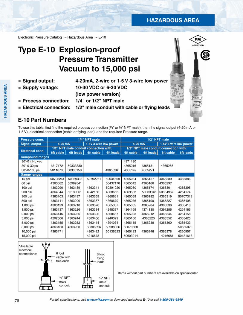
76
HAZ
ARD
OU
S AR
EA
HAZARDOUS AREA
For full specifications, visit www.wika.com to download datasheet E-10 or call 1-800-381-6549
Electronic Pressure Catalog > Hazardous Area > E-10
Type E-10 Explosion-proof Pressure Transmitter Vacuum to 15,000 psi Signal output: 4-20mA, 2-wire or 1-5 V 3-wire low power Supply voltage: 10-30 VDC or 6-30 VDC (low power version) Process connection: 1/4" or 1/2" NPT male Electrical connection: 1/2" male conduit with cable or flying leads
6 foot cable with free ends
½" NPT male conduit
6 foot flying leads
½" NPT male conduit
*Available electrical connections:
Items without part numbers are available on special order.
Pressure conn. 1/4" NPT male 1/2" NPT male Signal output 4-20 mA 1-5V 3-wire low power 4-20 mA 1-5V 3-wire low power
Electrical conn. 1/2" NPT male conduit connection with: 1/2" NPT male conduit connection with:
6ft cable 6ft leads 6ft cable 6ft leads 6ft cable 6ft leads 6ft cable 6ft leadsCompound ranges 30"-0 inHg vac 4371130 30"-0-30 psi 4217172 50333330 4365016 4365131 4365255 30"-0-100 psi 50116703 50300150 4365026 4365149 4365271 Gauge ranges 15 psi 50792261 50989333 50792261 50034669 4365034 4365157 4365389 4365386 60 psi 4363082 50989341 50437178 4365042 4365166 4365297 100 psi 4363090 4363189 4363341 50391020 4365050 4365174 4365301 4365395 200 psi 4364844 50139061 4242150 4368653 4369633 50033948 50834967 4254174 300 psi 4363103 4363197 4363359 4368661 4365068 4365182 4365319 50707319 500 psi 4363111 4363200 4363367 4368679 4365076 4365190 4365327 4365408 1,000 psi 4363129 4363218 4363376 4365337 4365085 4365204 4365336 4365418 1,500 psi 4363137 4363226 4363384 4248337 4364169 4374130 4391256 4254166 2,000 psi 4363146 4363236 4363392 4368687 4365093 4365212 4365344 4254158 3,000 psi 4202506 4363244 4363406 4248329 4365106 4365220 4365352 4365425 5,000 psi 4363155 4363252 4363414 4394034 4365115 4365238 4365360 4365433 8,000 psi 4363163 4363260 50308696 50988906 50070568 50555022 10,000 psi 4363171 4363422 50136623 4365123 4365246 4365378 4260957 15,000 psi 4216673 50603914 4216681 50131613
To use this table, first find the required process connection (1/4” or ½” NPT male), then the signal output (4-20 mA or 1-5 V), electrical connection (cable or flying lead), and the required Pressure range.
E-10 Part Numbers

77
HAZARD
OU
S AREA
HAZARDOUS AREA
For full specifications, visit www.wika.com to download datasheet E-10 or call 1-800-381-6549
Electronic Pressure Catalog > Hazardous Area > E-10
E-10 Smart Codes for Custom Order Configurations Field no. Code Feature
Signal output A 4 ... 20 mA, 2-wire K 1 ... 5 V, 3-wire1 ? Other - please specify Unit P psi 3 psi absolute2 ? Other - please specify Pressure range CA -30 inHg ... 0 CD -30 inHg ... 30 psi CF -30 inHg ... 60 psi CH -30 inHg ... 100 psi CL -30 inHg ... 200 psi CN 0 psi ... 5 psi CP 0 psi ... 10 psi BC 0 psi ... 15 psi (0 psi ... 15 psi absolute) CQ 0 psi ... 25 psi (0 psi ... 25 psi absolute) BD 0 psi ... 30 psi DA 0 psi ... 50 psi (0 psi ... 50 psi absolute) BE 0 psi ... 60 psi BF 0 psi ... 100 psi (0 psi ... 100 psi absolute) BG 0 psi ... 160 psi BH 0 psi ... 200 psi DG 0 psi ... 250 psi BI 0 psi ... 300 psi DI 0 psi ... 500 psi DJ 0 psi ... 750 psi BN 0 psi ... 1,000 psi BO 0 psi ... 1,500 psi BP 0 psi ... 2,000 psi BQ 0 psi ... 3,000 psi BS 0 psi ... 5,000 psi DS 0 psi ... 8,000 psi BT 0 psi ... 10,000 psi BU 0 psi ... 15,000 psi3 ?? Other - please specify Process connection NB 1/4" NPT ND 1/2" NPT4 ?? Other - please specify
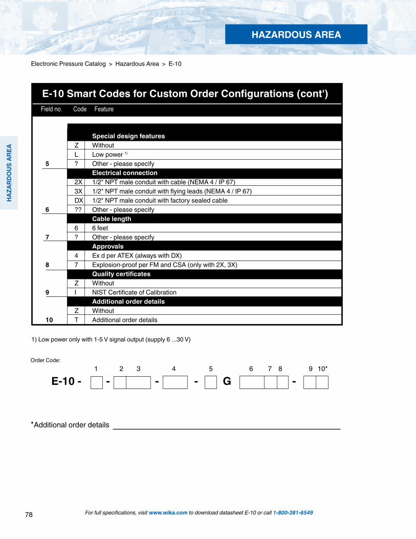
78
HAZ
ARD
OU
S AR
EA
HAZARDOUS AREA
For full specifications, visit www.wika.com to download datasheet E-10 or call 1-800-381-6549
Electronic Pressure Catalog > Hazardous Area > E-10
1 2 3 4 5 6 7 8 9 10*
E-10 - - - - G -
*Additional order details
Order Code:
E-10 Smart Codes for Custom Order Configurations (cont') Field no. Code Feature
1) Low power only with 1-5 V signal output (supply 6 ...30 V)
Special design features Z Without L Low power 1)
5 ? Other - please specify Electrical connection 2X 1/2" NPT male conduit with cable (NEMA 4 / IP 67) 3X 1/2" NPT male conduit with flying leads (NEMA 4 / IP 67) DX 1/2" NPT male conduit with factory sealed cable6 ?? Other - please specify Cable length 6 6 feet 7 ? Other - please specify 8 Approvals 4 Ex d per ATEX (always with DX)8 7 Explosion-proof per FM and CSA (only with 2X, 3X) Quality certificates Z Without9 I NIST Certificate of Calibration Additional order details Z Without10 T Additional order details
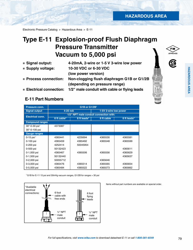
79
HAZARD
OU
S AREA
HAZARDOUS AREA
For full specifications, visit www.wika.com to download datasheet E-11 or call 1-800-381-6549
Electronic Pressure Catalog > Hazardous Area > E-11
Type E-11 Explosion-proof Flush Diaphragm Pressure Transmitter Vacuum to 5,000 psi
Pressure conn. G1B or G1/2B1 Signal output 4-20 mA 1-5V 3-wire low power
Electrical conn. 1/2" NPT male conduit connection with:
6 ft cable* 6 ft leads* 6 ft cable 6 ft leads*Compound ranges 30"-0-30 psi1 4373087 30"-0-100 psi Gauge ranges0-15 psi 1 4365441 4235694 4365530 43655810-100 psi 4365459 4365492 4365548 43655990-200 psi 4252414 50045954 0-500 psi 50132423 43656110-1,000 psi 4365467 4365506 4365556 43656290-1,500 psi 50132440 43656370-2,000 psi 50055712 43656460-3,000 psi 4365476 4365514 4365565 43656540-5,000 psi 4365484 4365522 4365573 4365662
1 G1B for E-11 15 psi and 30inHg vacuum ranges, G1/2B for ranges > 30 psi
Items without part numbers are available on special order.
E-11 Part Numbers
Signal output: 4-20mA, 2-wire or 1-5 V 3-wire low power Supply voltage: 10-30 VDC or 6-30 VDC (low power version) Process connection: Non-clogging flush diaphragm G1B or G1/2B (depending on pressure range) Electrical connection: 1/2" male conduit with cable or flying leads
6 foot cable with free ends
½" NPT male conduit
6 foot flying leads
½" NPT male conduit
*Available electrical connections:

80
HAZ
ARD
OU
S AR
EA
HAZARDOUS AREA
For full specifications, visit www.wika.com to download datasheet E-11 or call 1-800-381-6549
Electronic Pressure Catalog > Hazardous Area > E-11
E-11 Smart Codes for Custom Order Configurations Field no. Code Feature
Signal output A 4 ... 20 mA, 2-wire K 1 ... 5 V, 3-wire1 ? Other - please specify Unit P psi 3 psi absolute2 ? Other - please specify Pressure range CA -30 inHg ... 0 CD -30 inHg ... 30 psi CF -30 inHg ... 60 psi CH -30 inHg ... 100 psi CL -30 inHg ... 200 psi CN 0 psi ... 5 psi CP 0 psi ... 10 psi BC 0 psi ... 15 psi (0 psi ... 15 psi absolute) CQ 0 psi ... 25 psi (0 psi ... 25 psi absolute) BD 0 psi ... 30 psi DA 0 psi ... 50 psi (0 psi ... 50 psi absolute) BE 0 psi ... 60 psi BF 0 psi ... 100 psi (0 psi ... 100 psi absolute) BG 0 psi ... 160 psi BH 0 psi ... 200 psi DG 0 psi ... 250 psi BI 0 psi ... 300 psi DI 0 psi ... 500 psi DJ 0 psi ... 750 psi BN 0 psi ... 1,000 psi BO 0 psi ... 1,500 psi BP 0 psi ... 2,000 psi BQ 0 psi ... 3,000 psi BS 0 psi ... 5,000 psi DS 0 psi ... 8,000 psi3 ?? Other - please specify Process connection 85 G1B, flush diaphragm with O-ring (up to 25 psi) 86 G1/2B, flush diaphragm with O-ring (> 30 psi)4 ? Other - please specify
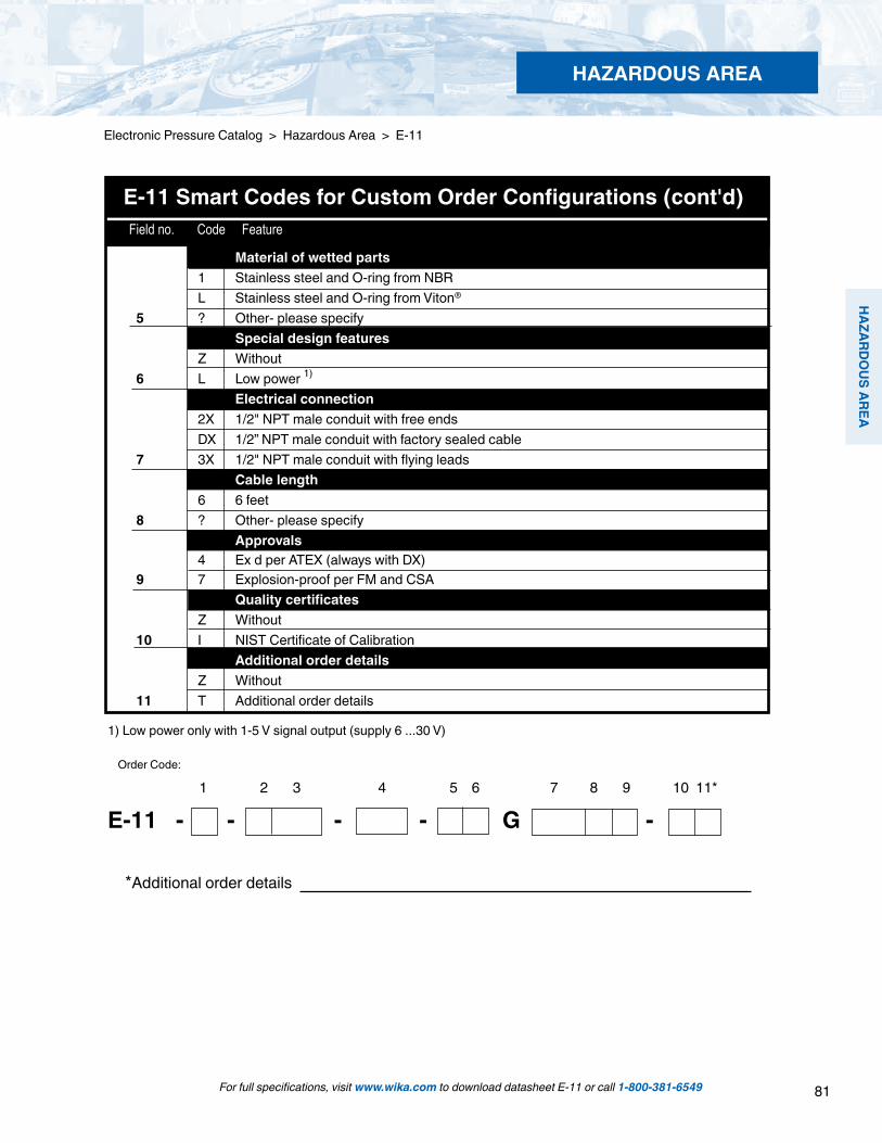
81
HAZARD
OU
S AREA
HAZARDOUS AREA
For full specifications, visit www.wika.com to download datasheet E-11 or call 1-800-381-6549
Electronic Pressure Catalog > Hazardous Area > E-11
Field no. Code Feature
E-11 Smart Codes for Custom Order Configurations (cont'd)
1) Low power only with 1-5 V signal output (supply 6 ...30 V)
*Additional order details
1 2 3 4 5 6 7 8 9 10 11*
E-11 - - - - G -
Order Code:
Material of wetted parts 1 Stainless steel and O-ring from NBR L Stainless steel and O-ring from Viton® 5 ? Other- please specify Special design features Z Without6 L Low power 1)
Electrical connection 2X 1/2" NPT male conduit with free ends DX 1/2” NPT male conduit with factory sealed cable 7 3X 1/2" NPT male conduit with flying leads Cable length 6 6 feet8 ? Other- please specify Approvals 4 Ex d per ATEX (always with DX)9 7 Explosion-proof per FM and CSA Quality certificates Z Without10 I NIST Certificate of Calibration Additional order details Z Without11 T Additional order details

82
HAZ
ARD
OU
S AR
EA
HAZARDOUS AREA
For full specifications, visit www.wika.com to download datasheets N-10, N-11 or call 1-800-381-6549
Applications
Natural gas compressors Wellhead monitoring Pipeline pressure General industrial applications
Special Features
FM approved non-incendive for Class I Division 2 hazardous locations Engineered to meet the harsh demands of gas compressor applications Does not require the use of intrinsically safe barriers NACE MR-01-75 compliant wetted parts 4-20 mA or low power 1-5 volt output signals available
Description
Type N-10 pressure transmitters are specifically designed to meet the durability and performance requirements of gas compressor systems. These pressure transmitters feature an industry standard 4-20 mA 2 wire signal output, NEMA 4X (IP 67) weather protection and are extremely resistant to pressure spikes, vibration and moisture intrusion. NACE MR-01-75 compliance provides extra resistance against sulfide stress cracking when exposed to gases containing sulphur.
Type N-11 pressure transmitters feature a flat, non-clogging diaphragm. This is designed for use with viscous fluids or me-dia containing particulates that could clog the pressure port of the standard NPT version.
The transmitters are engineered to meet Class I Division 2 non-incendive protection requirements in hazardous environments. Each undergoes extensive quality control testing and calibration to achieve a linearity of < 0.25% full scale. In addition, each pressure transmitter is temperature compensated to assure accuracy and long term stability when exposed to severe ambient temperature variations.
Left: N-10 pressure transmitter with NPT connectionRight: N-11 flush diaphragm pressure transmitter
Electronic Pressure Catalog > Hazardous Area > N-10, N-11
Type N-10, N-11 Hazardous Area Non-incendive Transmitters
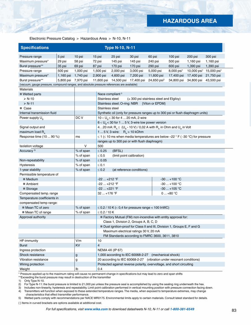
83
HAZARD
OU
S AREA
HAZARDOUS AREA
For full specifications, visit www.wika.com to download datasheets N-10, N-11 or call 1-800-381-6549
Electronic Pressure Catalog > Hazardous Area > N-10, N-11
Specifications Type N-10, N-11
Pressure range 5 psi 10 psi 15 psi 25 psi 30 psi 60 psi 100 psi 200 psi 300 psiMaximum pressure* 29 psi 58 psi 72 psi 145 psi 145 psi 240 psi 500 psi 1,160 psi 1,160 psiBurst pressure** 35 psi 69 psi 87 psi 170 psi 170 psi 290 psi 600 psi 1,390 psi 1,390 psiPressure range 500 psi 1,000 psi 1,500 psi 2,000 psi 3,000 psi 5,000 psi 8,000 psi1 10,000 psi1 15,000 psi1Maximum pressure* 1,160 psi 1,740 psi 2,900 psi 4,600 psi 7,200 psi 11,600 psi 17,400 psi 17,400 psi 21,750 psiBurst pressure** 5,800 psi 7,970 psi 11,600 psi 14,500 psi 17,400 psi 24,650 psi2 34,800 psi 34,800 psi 43,500 psivacuum, gauge pressure, compound ranges, and absolute pressure references are availableMaterials Wetted parts Nace compliant 5
N-10 Stainless steel (> 300 psi stainless steel and Elgiloy) N-11 Stainless steel; O-ring: NBR Viton or EPDM Case Stainless steelInternal transmission fluid Synthetic oil (only for pressure ranges up to 300 psi or flush diaphragm units)Power supply UB DC V 10 < UB ≤ 30 for 4 ... 20 mA, 2-wire
6 < UB < 30 for 1 ... 5 V, 3-wire low power versionSignal output and 4…20 mA: RA ≤ (UB - 10 V) / 0,02 A with RA in Ohm and UB in Volt maximum load RA 1 ... 5 V, 3-wire: RA > 10 kOhmResponse time (10 ... 90 %) ms ≤ 1 (≤ 10 ms when media temperatures are below –22 ° F ( -30 °C) for pressure
ranges up to 300 psi or with flush diaphragm)Isolation voltage V 500Accuracy 3) % of span ≤ 0.25 (BFSL)
% of span ≤ 0.5 (limit point calibration)Non-repeatability % of span ≤ 0.05Hysteresis % of span ≤ 0.11-year stability % of span ≤ 0.2 (at reference conditions)Permissible temperature of Medium -22 ... +212 °F -30 ... +100 °C Ambient -22 ... +212 °F -30 ... +100 °C Storage -22 ... +221 °F -30 ... +105 °C Compensated temp. range 32 ... +176 °F 0 ... +80 °CTemperature coefficients incompensated temp range: Mean TC of zero % of span ≤ 0.2 / 10 K (< 0,4 for pressure range < 100 InWC) Mean TC of range % of span ≤ 0.2 / 10 KApproval authority Factory Mutual (FM) non-incendive with entity approval for:
Class 1, Division 2, Groups A, B, C, D Dust ignition-proof for Class II and III, Division 1, Groups E, F and G
Maximum electrical ratings 30 V, 20 mA FM Standards according to FMRC 3600, 3611, 3810
HF-immunity V/m 10 Burst KV 4Ingress protection NEMA 4X (IP 67)Shock resistance g 1,000 according to IEC 60068-2-27 (mechanical shock)Vibration resistance g 20 according to IEC 60068-2-27 (vibration under resonant conditions)Wiring protection Protected against reverse polarity, overvoltage, and short circuitingWeight lb 0.4
* Pressure applied up to the maximum rating will cause no permanent change in specifications but may lead to zero and span shifts**Exceeding the burst pressure may result in destruction of the transmitter1) Only Type N-10.2) For Type N-11: the burst pressure is limited to 21,000 psi unless the pressure seal is accomplished by using the sealing ring underneath the hex.3) Includes non-linearity, hysteresis and repeatability. Limit point calibration performed in vertical mounting position with pressure connection facing down.4) Transmitters will function when exposed to these extended temperature ranges. The media, when exposed to temperature extremes, may change
characteristics that effect transmitter performance.5) Wetted parts comply with recommendations per NACE MR0175. Environmental limits apply to certain materials. Consult latest standard for details. Items in curved brackets are options available at additional cost.

84
HAZ
ARD
OU
S AR
EA
HAZARDOUS AREA
For full specifications, visit www.wika.com to download datasheet N-11 or call 1-800-381-6549
Electronic Pressure Catalog > Hazardous Area > N-10, N-11
6 foot cable with free endsNEMA 4 / IP 67Order code: 2X
Dimensions in inches (mm)
Case
Electrical connection
2.28
“ (58
mm
)1.06“ (27mm)
Sealing ring29.7x35.7x2.0
O-ring 26x2
N-11 G 1 50 InWC to 25 psiOrder code: 85
N-11 G 1/230 psi to 5,000 psiOrder code: 86
Sealing ring18.5x23.9x1.5
O-ring 15x21.26
”(31.
9mm
)
.81”
(20.
5mm
)
.39”
(10m
m)
1.22
”(31m
m)
.81”
(20.
5mm
)
.39”
(10m
m)
N-11 flush diaphragm pressure connections
N-10 pressure connections
1/ 2 NPT maleOrder code: ND
1/4 NPT maleOrder code: NB
G 1/2 EN 837Order code: GD
G 1/4EN 837Order code: GB
.85”
(21.
5mm
)
1.08
”(27.
5mm
)
.51”
(13m
m)
.75”
(19m
m)
1.12
”(28.
5mm
).7
9”(2
0mm
)
.32”
(8m
m)
.12”
(3m
m)
O .24”(6mm)
O .69” (17.5mm)
.85”
(21.
5mm
).5
1”(1
3mm
)
O .20”(5mm)
.08”
(2m
m)
.08”
(2m
m)
O .37”(9.5mm)
1.06“ (27mm)

85
HAZARD
OU
S AREA
HAZARDOUS AREA
For full specifications, visit www.wika.com to download datasheet N-11 or call 1-800-381-6549
Electronic Pressure Catalog > Hazardous Area > N-10, N-11
3-wire system2-wire system
brown
green
brown
white
green
shield / case
Matching P-1 weld insert adapters for N-11 flush diaphragm transmitters
P-1 G1/2 weld insert adapterPart # 1097008
for pressure ranges > 30 psi
P-1 G1 weld insert adapterPart # 1206974
for pressure ranges < 25 psiCross section view of P-1 adapter installed in pipe.
weld
Wiring details
shield / case
Legend:
Sig+ output signal positiveUB+ power supply positive0V power supply negativeSig - output signal negative
6 foot cable with free ends

86
HAZ
ARD
OU
S AR
EA
HAZARDOUS AREA
For full specifications, visit www.wika.com to download datasheet N-10 or call 1-800-381-6549
Electronic Pressure Catalog > Hazardous Area > N-10
Type N-10 Hazardous Area Non-incendive Transmitter Vacuum to 15,000 psi
Standard Features
Signal output: 4-20 mA 2-wire or 1-5 V 3-wire Supply voltage: 10-30 DC (6-30 VDC for 1-5 V version) Process connection: 1/4 NPT Male Electrical connection: 1/2" NPT male conduit with 6 foot cable
N-10 Gauge Ranges Description Range Part # 4-20 mA 2-wire 1-5 V 3-wire
30" INHG Vacuum 4348296 435461930"-0-30 psi 4348309 435462730"-0-100 psi 4332431 43546360-15 psi 4348317 43546440-30 psi 4348326 43546520-60 psi 4348334 43546600-100 psi 4348342 43546780-200 psi 4348350 43546860-300 psi 4348368 43546950-500 psi 4346216 43547080-1,000 psi 4332440 43547160-1,500 psi 4338597 43547250-2,000 psi 4348376 43547330-3,000 psi 4347000 43547410-5,000 psi 4347018 43547590-8,000 psi 4348385 43547670-10,000 psi 4348393 43547760-15,000 psi 4348406 4354784
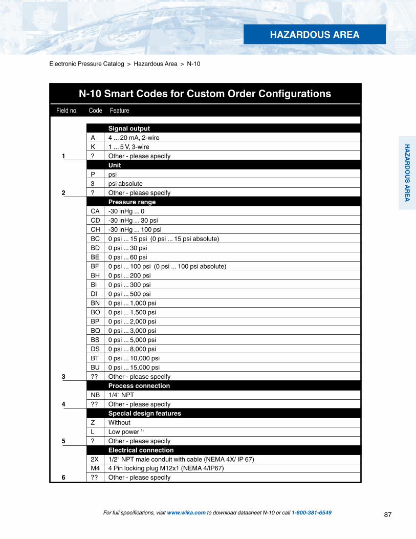
87
HAZARD
OU
S AREA
HAZARDOUS AREA
Electronic Pressure Catalog > Hazardous Area > N-10
For full specifications, visit www.wika.com to download datasheet N-10 or call 1-800-381-6549
N-10 Smart Codes for Custom Order Configurations Field no. Code Feature
Signal output A 4 ... 20 mA, 2-wire K 1 ... 5 V, 3-wire1 ? Other - please specify Unit P psi 3 psi absolute2 ? Other - please specify Pressure range CA -30 inHg ... 0 CD -30 inHg ... 30 psi CH -30 inHg ... 100 psi BC 0 psi ... 15 psi (0 psi ... 15 psi absolute) BD 0 psi ... 30 psi BE 0 psi ... 60 psi BF 0 psi ... 100 psi (0 psi ... 100 psi absolute) BH 0 psi ... 200 psi BI 0 psi ... 300 psi DI 0 psi ... 500 psi BN 0 psi ... 1,000 psi BO 0 psi ... 1,500 psi BP 0 psi ... 2,000 psi BQ 0 psi ... 3,000 psi BS 0 psi ... 5,000 psi DS 0 psi ... 8,000 psi BT 0 psi ... 10,000 psi BU 0 psi ... 15,000 psi3 ?? Other - please specify Process connection NB 1/4" NPT4 ?? Other - please specify Special design features Z Without L Low power 1)
5 ? Other - please specify Electrical connection 2X 1/2" NPT male conduit with cable (NEMA 4X/ IP 67) M4 4 Pin locking plug M12x1 (NEMA 4/IP67)6 ?? Other - please specify

88
HAZ
ARD
OU
S AR
EA
HAZARDOUS AREA
Electronic Pressure Catalog > Hazardous Area > N-10
For full specifications, visit www.wika.com to download datasheet N-10 or call 1-800-381-6549
1 2 3 4 5 6 7 8 9 10*
N-10 - - - - G -
*Additional order details
Order Code:
N-10 Smart Codes for Custom Order Configurations (cont'd) Field no. Code Feature
1) Low power only with 1-5 V signal output (supply 6 ...30 V).
Cable length 6 6 feet 1 10 feet 2 20 feet 3 30 feet 7 ? Other - please specify Approvals N EEx nA II 3G T6 7 II 3D per ATEX (always with M4)8 F FM, CSA non-incendive (always with 2X) Quality certificates Z Without9 I NIST Certificate of Calibration Additional order details Z Without10 T Additional order details
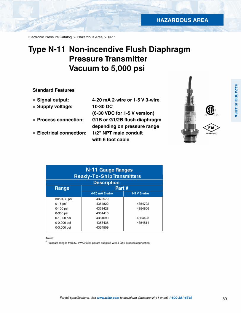
89
HAZARD
OU
S AREA
HAZARDOUS AREA
Standard Features
Signal output: 4-20 mA 2-wire or 1-5 V 3-wire Supply voltage: 10-30 DC (6-30 VDC for 1-5 V version) Process connection: G1B or G1/2B flush diaphragm depending on pressure range Electrical connection: 1/2" NPT male conduit with 6 foot cable
30"-0-30 psi 4372579 0-15 psi1 4354822 43547920-100 psi 4358428 43548060-300 psi 4364410 0-1,000 psi 4364690 43644280-2,000 psi 4358436 43548140-3,000 psi 4364509
N-11 Gauge Ranges Ready-To-ShipTransmitters Description Range Part # 4-20 mA 2-wire 1-5 V 3-wire
For full specifications, visit www.wika.com to download datasheet N-11 or call 1-800-381-6549
Electronic Pressure Catalog > Hazardous Area > N-11
Type N-11 Non-incendive Flush Diaphragm Pressure Transmitter Vacuum to 5,000 psi
Notes:1
Pressure ranges from 50 InWC to 25 psi are supplied with a G1B process connection.

90
HAZ
ARD
OU
S AR
EA
HAZARDOUS AREA
Electronic Pressure Catalog > Hazardous Area > N-11
For full specifications, visit www.wika.com to download datasheet N-11 or call 1-800-381-6549
N-11 Smart Codes for Custom Order Configurations Field no. Code Feature
Signal output A 4 ... 20 mA, 2-wire K 1 ... 5 V, 3-wire1 ? Other - please specify Unit P psi 3 psi absolute2 ? Other - please specify Pressure range CA -30 inHg ... 0 CD -30 inHg ... 30 psi CH -30 inHg ... 100 psi BC 0 psi ... 15 psi (0 psi ... 15 psi absolute) BD 0 psi ... 30 psi BE 0 psi ... 60 psi BF 0 psi ... 100 psi (0 psi ... 100 psi absolute) BH 0 psi ... 200 psi BI 0 psi ... 300 psi DI 0 psi ... 500 psi BN 0 psi ... 1,000 psi BO 0 psi ... 1,500 psi BP 0 psi ... 2,000 psi BQ 0 psi ... 3,000 psi BS 0 psi ... 5,000 psi DQ 0 psi ... 6,000 psi DR 0 psi ... 7,500 psi DS 0 psi ... 8,000 psi3 ?? Other - please specify Process connection 85 G1B, flush diaphragm with O-ring (50 InWC to 25 psi)4 86 G1/2B, flush diaphragm with O-ring (> 30 psi) Material of wetted parts B Stainless steel and O-ring from EPDM L Stainless steel and O-ring from Viton® 5 ? Other- please specify Special design features Z Without 6 L Low power 1) Electrical connection 2X 1/2" NPT male conduit with cable (NEMA 4X / IP 67) M4 4 Pin locking plug M12x1 (NEMA 4/IP67)7 ?? Other- please specify
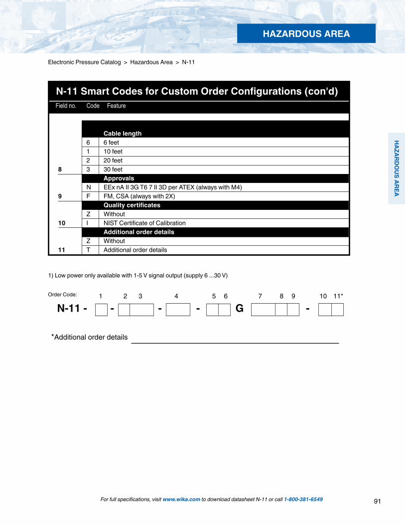
91
HAZARD
OU
S AREA
HAZARDOUS AREA
Electronic Pressure Catalog > Hazardous Area > N-11
For full specifications, visit www.wika.com to download datasheet N-11 or call 1-800-381-6549
*Additional order details
N-11 Smart Codes for Custom Order Configurations (con'd) Field no. Code Feature
1) Low power only available with 1-5 V signal output (supply 6 ...30 V)
1 2 3 4 5 6 7 8 9 10 11*
N-11 - - - - G -Order Code:
Cable length 6 6 feet 1 10 feet 2 20 feet 8 3 30 feet Approvals N EEx nA II 3G T6 7 II 3D per ATEX (always with M4)9 F FM, CSA (always with 2X) Quality certificates Z Without 10 I NIST Certificate of Calibration Additional order details Z Without 11 T Additional order details

92
HAZ
ARD
OU
S AR
EA
HAZARDOUS AREA
For full specifications, visit www.wika.com to download datasheet IS-20 or call 1-800-381-6549
Left: IS-20-S standard versionCenter: IS-21-S with flush diaphragmRight: IS-20-F with integral junction box
Applications
Chemical, petrochemical Oil and gas refining Food industry Mechanical engineering
Special Features
Pressure ranges from 50 InWC to 15,000 psi FM, CSA approval for - Intrinsically safe Class I, II and III Division 1, Group A, B, C, D, E, F, G - Dust Class II and III Division 1, Group E, F, G - Class I, Zone 0, AEx ia II C Ex- protection EEx ia I/II C T6 according to ATEX for: Gases, vapors and mist: Connection to Zone 0, Zone 1 and Zone 2 Dust: Connection to Zone 20, Zone 21 and Zone 22 Mining: Category M1 and M2 Suitable for SIL 2 according to IEC 61508 / IEC 61511
The IS-21-S and IS-21-F transmitters feature a flush diaphragm process connection. They are specifically designed for the measurement of viscous fluids or media containing solids that may clog a NPT process connection.
Types IS-20-F and IS-21-F feature an integral stainless steel junction box with internal terminal block for use in extremely harsh environments. A ½“ NPT female conduit connection is standard on all models and a cable compression electrical con-nection is available as an option.
All types require a 10 to 30 volt supply provided by an intrinsically safe power supply or through an approved intrinsically safe zener diode barrier.
Electronic Pressure Catalog > Hazardous Area > IS-20, IS-21, IS-20-F, IS-21-F
Type IS-20, IS-21, IS-20-F, IS-21-F Intrinsically Safe Hazardous Area Transmitters
Description
Approvals meet international standardsThe IS-20 series of intrinsically safe pressure transmitters are designed for industrial pressure measurement applications in hazardous areas where intrinsically safe ratings are required.
Multiple intrinsically safe approvals include FM, ATEX and CSA. These multiple approvals provide for global recognition and acceptance of the intrinsically safe ratings. The transmitters are labeled with all three approvals to help support international shipments of OEM equipment designed with these transmitters.
Rugged constructionThe stainless steel wetted parts feature an all-welded mea-suring cell for improved media compatibility. There are no internal soft sealing materials that may react with the media or deteriorate over time. The compact case is also made of stainless steel and is available with environmental protection ratings up to NEMA 6 ( IP 68).

93
HAZARD
OU
S AREA
HAZARDOUS AREA
For full specifications, visit www.wika.com to download datasheet IS-20 or call 1-800-381-6549
Electronic Pressure Catalog > Hazardous Area > IS-20, IS-21, IS-20-F, IS-21-F
Specifications Type IS-20-S, IS-21-S, IS-20-F, IS-21-F
Specifications without type designation apply for all types.Pressure range 50 InWC 5 psi 10 psi 25 psi 30 psi 60 psi 100 psi 160 psi 200 psiMaximum pressure* 15 psi 29 psi 58 psi 145 psi 145 psi 240 psi 500 psi 1,160 psi 1,160 psiBurst pressure** 29 psi 35 psi 69 psi 170 psi 170 psi 290 psi 600 psi 1,390 psi 1,390 psiPressure range 300 psi 500 psi 1,000 psi 2,000 psi 3,000 psi 5,000 psi 8,000 psi 10,000 psi1 15,000 psi1Maximum pressure* 1,160 psi 1,160 psi 1,740 psi 4,600 psi 7,200 psi 11,600 psi 17,400 psi 17,400 psi 21,750 psiBurst pressure** 1,390 psi 5,800 psi 7,970 psi 14,500 psi 17,400 psi 24,650 psi2 34,800 psi2 34,800 psi 43,500 psivacuum, gauge pressure, compound ranges, and absolute pressure references are available1) Ranges only available with Type IS-20 2) For Type IS-21 the burst pressure is limited to 21,000 psi unless the pressure seal is accomplished by using the sealing ring underneath the hex. *Pressure applied up to the maximum rating will cause no permanent change in specifications but may lead to zero and span shifts **Exceeding the burst pressure may result in destruction of the transmitter and possible loss of mediaMaterials Wetted parts (for other materials see WIKA diaphragm seal program) Types IS-20-S, IS-20-F Stainless steel Types IS-21-S, IS-21-F Stainless steel Hastelloy® C4
O-ring: NBR Viton® or EPDM Case Stainless steel Internal transmission fluid 3) Synthetic oil Halocarbon® oil for oxygen applications 4) Listed by FDA for food
applications 3) Not available with Type IS-20 in pressure ranges > 300 psi4) Media temperature for oxygen version: -4 ... +140 °CF (-20 ... +60 °C). Not available in vacuum or absolute pressure ranges or in Type IS-21 flush diaphragm version > 500 psi
Power supply UB DC V 10 < UB ≤ 30 (11 < UB < 30 with Type IS-20 -F)Signal output and 4 ... 20 mA, 2-wire Maximum load RA
Types IS-20-S RA ≤ (UB – 10 V) / 0.02 A – (length of cable in feet x 0.043 Ohm) Types IS-20-F RA ≤ (UB – 11 V) / 0.02 A
with RA in Ohms and UB in VoltsTest circuit signal / max. load RA RA < 15 Ohm (only for Type IS-20 -F)Adjustability zero/span % ± 5 using potentiometers inside the instrumentResponse time (10 ... 90 %) ms < 1 (< 10 ms at media temperatures below –22°F (-30°C) for ranges < 300 psiPower Pi W 1 (750 mW with approval for Category 1D)Isolation voltage Isolation complies with EN 50020, 79-11Accuracy 5) % of span ≤ 0.25 0.125 6) (BFSL)
% of span ≤ 0.5 0.25 6) (limit point calibration)5) Including non-linearity, hysteresis and repeatability. Limit point Calibration performed in vertical mounting position with pressure connection facing down.6) For pressure ranges above 100 InWC
Non-linearity % of span ≤ 0.2 (BFSL) according to IEC 61298-2Non-repeatability % of span ≤ 0.11-year stability % of span ≤ 0.2 (at reference conditions)Permissible temperature Medium 7) 8) -20 ... +80 °C 7) -4 ... +176 °F 7)
extended temperature ranges see page 6 7)
Ambient 7) 8) -20 ... +80 °C 7) -4 ... +176 °F 7)
Storage 8) -30 ... +105 °C -22 ... +221 °F7) Other temperature ranges are possible, depending on the electrical connection; see EC-type8) Also complies with EN 50178, Tab. 7, Type C, Class 4KH Operation, 1K4 Storage, 1K3 Transport9) Response time for IS-20: < 10 ms at medium temp. below -30 °C (-22 °F) for pressure ranges up to 300 psi Response time for IS-21: < 10 ms at medium temp. below -30 °C (-22 °F) for all pressure ranges
Compensated temperature range 32 ... +176°F 0 ... +80°CTemperature coefficients (TC) withincompensated temperature range: Mean TC of zero % of span ≤ 0.2 / 10 K (< 0.4 for pressure range < 100 InWC) Mean TC of range % of span ≤ 0.2 / 10 KCE-conformity Pressure equipment directive 97/23/EC EMC directive 2004/108/EC, EN 61 326 Emission (Group 1, Class B) and
Immunity (industrial locations)
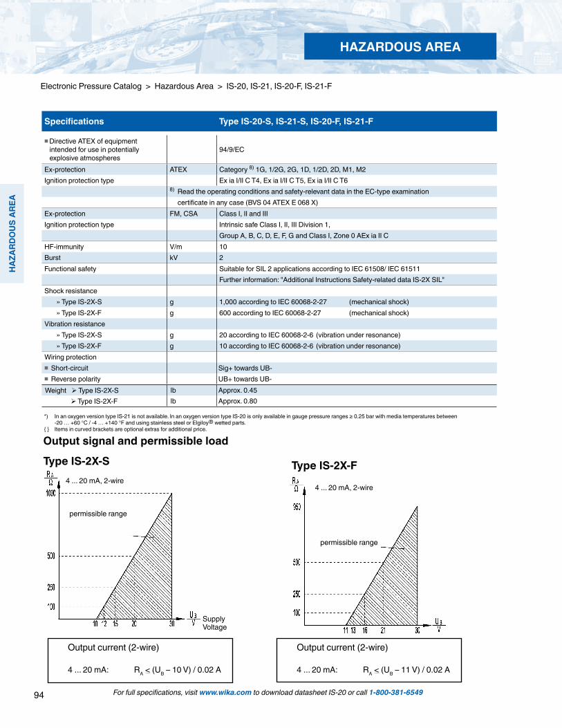
94
HAZ
ARD
OU
S AR
EA
HAZARDOUS AREA
Output current (2-wire)
4 ... 20 mA: RA < (UB – 10 V) / 0.02 A
Output signal and permissible load
Type IS-2X-S4 ... 20 mA, 2-wire
permissible range
4 ... 20 mA, 2-wire
permissible range
Output current (2-wire)
4 ... 20 mA: RA < (UB – 11 V) / 0.02 A
Type IS-2X-F
Supply Voltage
For full specifications, visit www.wika.com to download datasheet IS-20 or call 1-800-381-6549
Electronic Pressure Catalog > Hazardous Area > IS-20, IS-21, IS-20-F, IS-21-F
Specifications Type IS-20-S, IS-21-S, IS-20-F, IS-21-F
Directive ATEX of equipment intended for use in potentially explosive atmospheres
94/9/EC
Ex-protection ATEX Category 8) 1G, 1/2G, 2G, 1D, 1/2D, 2D, M1, M2Ignition protection type Ex ia I/II C T4, Ex ia I/II C T5, Ex ia I/II C T6
8) Read the operating conditions and safety-relevant data in the EC-type examination certificate in any case (BVS 04 ATEX E 068 X)
Ex-protection FM, CSA Class I, II and IIIIgnition protection type Intrinsic safe Class I, II, III Division 1,
Group A, B, C, D, E, F, G and Class I, Zone 0 AEx ia II CHF-immunity V/m 10Burst kV 2Functional safety Suitable for SIL 2 applications according to IEC 61508/ IEC 61511
Further information: "Additional Instructions Safety-related data IS-2X SIL"Shock resistance » Type IS-2X-S g 1,000 according to IEC 60068-2-27 (mechanical shock) » Type IS-2X-F g 600 according to IEC 60068-2-27 (mechanical shock)Vibration resistance » Type IS-2X-S g 20 according to IEC 60068-2-6 (vibration under resonance) » Type IS-2X-F g 10 according to IEC 60068-2-6 (vibration under resonance)Wiring protection Short-circuit Sig+ towards UB- Reverse polarity UB+ towards UB-
Weight Type IS-2X-S lb Approx. 0.45 Type IS-2X-F lb Approx. 0.80
*) In an oxygen version type IS-21 is not available. In an oxygen version type IS-20 is only available in gauge pressure ranges ≥ 0.25 bar with media temperatures between -20 … +60 °C / -4 … +140 °F and using stainless steel or Elgiloy® wetted parts. Items in curved brackets are optional extras for additional price.
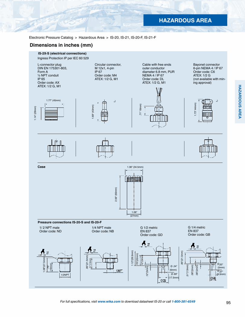
95
HAZARD
OU
S AREA
HAZARDOUS AREA
For full specifications, visit www.wika.com to download datasheet IS-20 or call 1-800-381-6549
Electronic Pressure Catalog > Hazardous Area > IS-20, IS-21, IS-20-F, IS-21-F
*) *)
Dimensions in inches (mm)
L-connector plugDIN EN 175301-803, Form A½ NPT conduitIP 65Order code: AXATEX: 1/2 G, M1
Circular connector,M 12x1, 4-pinIP 67Order code: M4ATEX: 1/2 G, M1
Cable with free endsouter conductordiameter 6.8 mm, PURNEMA 4 / IP 67Order code: DLATEX: 1/2 G, M1
Bayonet connector6-pin NEMA 4 / IP 67Order code: C6 ATEX: 1/2 G(not available with min-ing approval)
Case
Pressure connections IS-20-S and IS-20-FG 1/2 metricEN 837Order code: GD
G 1/4 metricEN 837Order code: GB
1/ 2 NPT maleOrder code: ND
1/4 NPT maleOrder code: NB
IS-2X-S (electrical connections) Ingress Protection IP per IEC 60 529
.71”
18m
m)
1.69
“ (43
mm
)
1.73
” 44m
m)
2.56
“ (65
mm
)
1.36“ (34.5mm)
1.06“ (27mm)
1.14
“ (29
mm
)
1.77“ (45mm)
1.08
”(27.
5mm
).7
5”
(19m
m)
1/2NPT
.85”
(21.
5mm
).5
1”(1
3mm
)
1.12
”(28.
5mm
)
.79”
(20m
m)
.12”
(3m
m)
.12”
(3m
m) .24”
(6mm) .69”
(17.5mm)
.85”
(21.
5mm
)
.51”
(13m
m)
.08”
(2m
m)
.08”
(2m
m) .20”
(5mm).37”
(9.5mm)
O
O
O
O

96
HAZ
ARD
OU
S AR
EA
**) European Hygienic Equipment Design Group Items in curved brackets are optional extras at additional cost.
Cable with free ends, zero/span not adjustable,conductor outer diameter 6.8 mm, PURIP 68/NEMA 6Order code: EMATEX: 1/2 G, M1
Integral junction box with internal springclip terminals NEMA 4X IP 67Order code:FE (1/2“ NPT female conduit standard) FH (threaded connection brass nickel-plated)FC (threaded connection stainless steel)ATEX: 1/2 G, M1
Electrical connections IS-2X-S
Electrical connections IS-2X-F
Other connectionsavailable
Electrical connections IS-2X -S
Cable with free ends, zero/span not adjustable,conductor outer diameter 7.5 mm, PUR FEPNEMA 6P / IP 68Order code: DMATEX: 1G, 1D, M1
2.60
”(66m
m)
1.24
”(31.
5mm
)
1.89”(48mm)
3.35”(85mm)
2.41”(61mm)
4.41
”(112
mm
)
1.06”(27mm)
2.13
”(54m
m)
1.06”(27mm)
1/2” NPT female conduit
Case dimensions
1.00
”(25.
5mm
)
Sealing ring29.7x35.7x2.0
O-ring 26x2
G 1 50 InWC to 25 psiOrder code: 85
G 1/230 psi to 8,000 psiOrder code: 86
Sealing ring18.5x23.9x1.5
O-ring 15x2
G 1according to EHEDG **) 100 InWC to 250 psiOrder code: 83
Sealing ring29.7x35.7x2.0
O-ring 21.82x3.53
IS-21-S and IS-21-F flush diaphragm pressure connections
1.26
”(31.
9mm
)
.81”
(20.
5mm
)
.39”
(10m
m)
1.22
”(31m
m)
.81”
(20.
5mm
)
.39”
(10m
m)
1.52
”(38.
5mm
)
.98”
(25m
m)
Matching P-1 weld insert adapters for IS-21-S and IS-21-F transmitters
P-1 G1/2 weld insert adapterPart # 1097008
for pressure ranges > 30 psi
P-1 G1 weld insert adapterPart # 1206974
for pressure ranges < 25 psi
Cross section view of P-1 adapter installed in pipe.
weld
For full specifications, visit www.wika.com to download datasheet IS-20 or call 1-800-381-6549
Electronic Pressure Catalog > Hazardous Area > IS-20, IS-21, IS-20-F, IS-21-F
HAZARDOUS AREA

97
HAZARD
OU
S AREA
For full specifications, visit www.wika.com to download datasheet IS-20 or call 1-800-381-6549
Electronic Pressure Catalog > Hazardous Area > IS-20, IS-21, IS-20-F, IS-21-F
Version
Cooling fins 2 3 5K * 0.47 0.68 0.76
*cooling constant specific to each version
Relationship of media temperature to ambient temperature
IS-21-S and IS-21-F, flush diaphragm-4 °F to 302 °F (-20 °C to 150 °C)
IS-20-S and IS-20-F-40 °F to 302 °F (-40 °C to 150 °C)
IS-20-S and IS-20-F-40 °F to 392 °F (-40 °C to 200 °C)
CBA
G 1/2with 2 cooling fins (version A )0 ... 30 psi up to 0 ... 8000 psiOrder code: 86 and C
1/2 NPT malewith 3 cooling fins (version B )0 - 5 psi to 0-15,000 psiOrder code: ND and 8
1/2 NPT malewith 5 cooling fins (version C )0-5 psi to 0-15,000 psiOrder code: ND and 9
Pressure connections for high temperature media
sealing ring 18,5x23,9x1,5
O-ring 15.0x2,0
Calculation of cooling element performance:TB = Tmed - (Tmed - Tamb) x KTB = Operating temperature of transmitterTmed = maximum temperature of process mediaTamb = maximum ambient temperatureK = Constant of cooling element
A C
Ambi
ent T
empe
ratu
re in
°C
Media Temperature in °C
Maximum permissible ambient temperature:Tamb = Tmed + (TB - Tmed) / K
B
3.27
”(83m
m)
.75”
(19m
m)
3.66
”(93m
m)
.75”
(19m
m)
1.22
”(30.
9mm
)
.39”
(10m
m)
1.79
”(45.
5mm
)
.81”
(20.
5mm
)
HAZARDOUS AREA

98
HAZ
ARD
OU
S AR
EA
HAZARDOUS AREA
Electrical connections Order-code Category Ambient/Medium temperature range
DIN 175301-803 A L-Connector A4 1/2 G (IIC)-40 ... +140 °F (T6)-40 ... +176 °F (T5)-40 ... +221 °F (T4)
-40 ... +60 °C (T6)-40 ... +80 °C (T5)-40 ... +105 °C (T4)
M1 -40 ... +221 °F -40 ... +105 °C
M 12x1 Circular connector M4 1/2 G (IIC)-13 ... +140 °F (T6)-13 ... +176 °F (T5)-13 ... +194 °F (T4)
-25 ... +60 °C (T6)-25 ... +80 °C (T5)-25 ... +90 °C (T4)
M1 -13 ... +194 °F -25 ... +90 °C
Cable DL 1/2 G (IIC)-4 ... +140 °F (T6)-4 ... +176 °F (T5)-4 ... +176 °F (T4)
-20 ... +60 °C (T6)-20 ... +80 °C (T5)-20 ... +80 °C (T4)
M1 -4 ... +140 °F -20 ... +60 °C
Bayonet connector(not with mining) C6 1/2 G (IIC)
-58 ... +140 °F (T6)-58 ... +176 °F (T5)-58 ... +221 °F (T4)
-50 ... +60 °C (T6)-50 ... +80 °C (T5)-50 ... +105 °C (T4)
Cablezero/span not adjustable EM 1/2 G (IIC)
-4 ... +140 °F (T6)-4 ... +176 °F (T5)-4 ... +176 °F (T4)
-20 ... +60 °C (T6)-20 ... +80 °C (T5)-20 ... +80 °C (T4)
M1 -4 ... +176 °F -20 ... +80 °C
Fieldcase FE, FH, FC 1/2 G (IIC)-58 ... +140 °F (T6)-58 ... +176 °F (T5)-58 ... +221 °F (T4
-50 ... +60 °C (T6)-50 ... +80 °C (T5)-50 ... +105 °C (T4
M1 -58 ... +221 °F (T4) -50 ... +105 °C (T4)
PUR Cablezero/span not adjustable DM 1 G (IIA), 1/2 G (IIC)
14 ... +140 °F (T6)14 ... +140 °F (T5)14 ... +140 °F (T4)
-10 ... +60 °C (T6)-10 ... +60 °C (T5)-10 ... +60 °C (T4)
1D, M1 14 ... +140 °F -10 ... +60 °C
FEP Cablezero/span not adjustable DM 1 G (IIA), 1/2 G (IIC)
-22 ... +140 °F (T6)-22 ... +176 °F (T5)-22 ... +221 °F (T4)
-30 ... +60 °C (T6)-30 ... +80 °C (T5)-30 ... +105 °C (T4)
1D -22 ... +140 °F -30 ... +60 °CM1 -22 ... +221 °F -30 ... +105 °C
Wiring detailsL-connectorDIN 175301-803 A
Circular connector M12x1, 4 pin
Cable, 1.5 m
2-wire U+ = 1 U- = 2 U+ = 1 U- = 3 U+ = brown U- = greenCable screen PUR-cable: grey
FEP-cable: twisted and tinnedWire gauge up to max.1.5 mm2 - 0.5 mm2 (AWG 20)
Cable diameter 6-8 mmship approval: 10-14 mm - 6.8 mm (Order code: DL / EM)
7.5 mm (Order code DM)Ingress protection according to IEC 60 529 IP 65 IP 67 IP 67 - Order code: DL
IP 68 zero/span not adjustable - Order code: EM / DMThe ingress protection classes specified only apply while the pressure transmitter is connected with female connectors that provide the corresponding ingress protection.Bayonet connector, 6 pin Field case (with internal spring clip terminals)
2-wire U+ = A U- = B U+ = 1 U- = 2 Test+ = 3 Test- = 4 screen = 5Cable diameter 7-13 mmIngress protection according to IEC 60 529 IP 67 IP 67
The ingress protection classes specified only apply while the pressure transmitter is connected with female connectors that provide the corresponding ingress protection.
Permissible temperature ranges depending on electrical connections
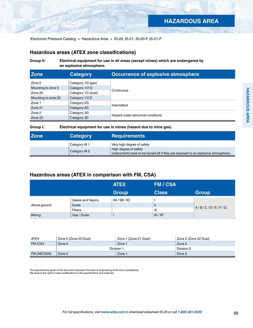
99
HAZARD
OU
S AREA
For full specifications, visit www.wika.com to download datasheet IS-20 or call 1-800-381-6549
Electronic Pressure Catalog > Hazardous Area > IS-20, IS-21, IS-20-F, IS-21-F
HAZARDOUS AREA
The specifications given in this document represent the state of engineering at the time of publishing.We reserve the right to make modifications to the specifications and materials.
ATEX FM / CSAGroup Class Group
Above groundGases and Vapors IIA / IIB / IIC I
A / B / C / D / E / F / GDusts IIFibers III
Mining Gas / Dusts I ID / IIF
Zone Category RequirementsCategory M 1 Very high degree of safety
Category M 2 High degree of safety (instruments have to be turned off if they are exposed to an explosive atmosphere)
Flammable material present continuously
Flammable material present intermittently
Flammable material normally not present
ATEX Zone 0 (Zone 20 Dust) Zone 1 (Zone 21 Dust) Zone 2 (Zone 22 Dust)FM /CSA Zone 0 Zone 1 Zone 2
Division 1 Division 2FM (NEC505) Zone 0 Zone 1 Zone 2
Zone Category Occurrence of explosive atmosphereZone 0 Category 1G (gas)
ContinuousMounting to zone 0 Category 1/2 G Zone 20 Category 1D (dust)Mounting to zone 20 Category 1/2 DZone 1 Category 2G
IntermittentZone 21 Category 2DZone 2 Category 3G
Hazard under abnormal conditionsZone 22 Category 3D
Group I: Electrical equipment for use in mines (hazard due to mine gas)
Hazardous areas (ATEX in comparison with FM, CSA)
Hazardous areas (ATEX zone classifications)Group II: Electrical equipment for use in all areas (except mines) which are endangered by an explosive atmosphere.
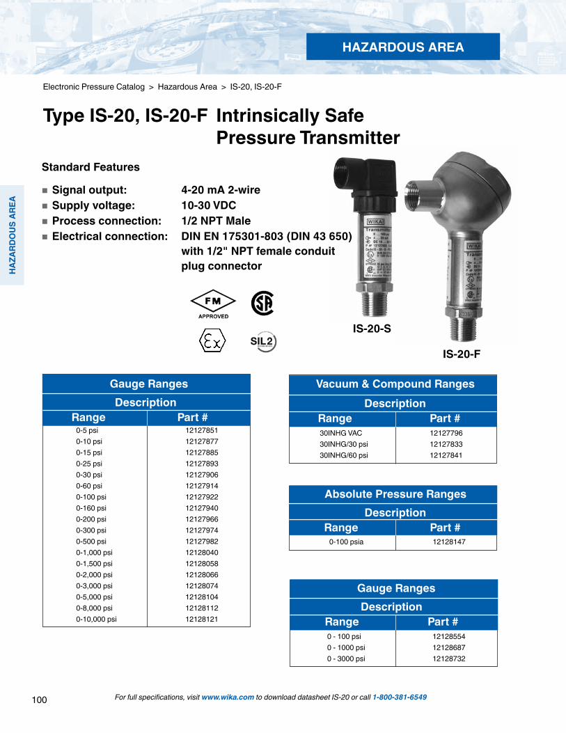
100
HAZ
ARD
OU
S AR
EA
For full specifications, visit www.wika.com to download datasheet IS-20 or call 1-800-381-6549
Electronic Pressure Catalog > Hazardous Area > IS-20, IS-20-F
Type IS-20, IS-20-F Intrinsically Safe Pressure Transmitter
HAZARDOUS AREA
Gauge Ranges Description Range Part #
Vacuum & Compound Ranges Description Range Part #
30INHG VAC 12127796 30INHG/30 psi 12127833 30INHG/60 psi 12127841
Absolute Pressure Ranges Description Range Part #
0-100 psia 12128147
0-5 psi 121278510-10 psi 12127877 0-15 psi 12127885 0-25 psi 121278930-30 psi 121279060-60 psi 121279140-100 psi 121279220-160 psi 121279400-200 psi 12127966 0-300 psi 121279740-500 psi 121279820-1,000 psi 121280400-1,500 psi 121280580-2,000 psi 121280660-3,000 psi 121280740-5,000 psi 121281040-8,000 psi 121281120-10,000 psi 12128121
Gauge Ranges Description Range Part #
0 - 100 psi 12128554 0 - 1000 psi 12128687 0 - 3000 psi 12128732
Standard Features
Signal output: 4-20 mA 2-wire Supply voltage: 10-30 VDC Process connection: 1/2 NPT Male Electrical connection: DIN EN 175301-803 (DIN 43 650) with 1/2" NPT female conduit plug connector
IS-20-S
IS-20-F
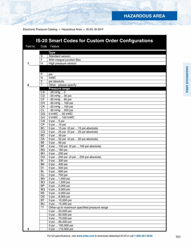
101
HAZARD
OU
S AREA
For full specifications, visit www.wika.com to download datasheet IS-20 or call 1-800-381-6549
Electronic Pressure Catalog > Hazardous Area > IS-20, IS-20-F
HAZARDOUS AREA
IS-20 Smart Codes for Custom Order Configurations Field no. Code Feature
Type S Standard version F With integral junction Box 1 H High pressure version Unit P psi N InWC 3 psi absolute 2 ? Other - please specify Pressure range CA -30 inHg ... 0 CD -30 inHg ... 30 psi CF -30 inHg ... 60 psi CH -30 inHg ... 100 psi CK -30 inHg ... 160 psi CL -30 inHg ... 200 psi GG 0 InWC ... 50 InWC GU 0 InWC ... 100 InWC CN 0 psi ... 5 psi CP 0 psi ... 10 psi BC 0 psi ... 15 psi (0 psi ... 15 psi absolute) CQ 0 psi ... 25 psi (0 psi ... 25 psi absolute) BD 0 psi ... 30 psi DA 0 psi ... 50 psi (0 psi ... 50 psi absolute) BE 0 psi ... 60 psi BF 0 psi ... 100 psi (0 psi ... 100 psi absolute) BG 0 psi ... 160 psi BH 0 psi ... 200 psi DG 0 psi ... 250 psi (0 psi ... 250 psi absolute) BI 0 psi ... 300 psi BK 0 psi ... 400 psi DI 0 psi ... 500 psi BL 0 psi ... 600 psi DJ 0 psi ... 750 psi BN 0 psi ... 1,000 psi BO 0 psi ... 1,500 psi BP 0 psi ... 2,000 psi BQ 0 psi ... 3,000 psi BS 0 psi ... 5,000 psi DS 0 psi ... 8,000 psi BT 0 psi ... 10,000 psi BU 0 psi ... 15,000 psi ?? Other-up to maximum specified pressure range 0 psi ... 25,000 psi 0 psi ... 60,000 psi 0 psi ... 75,000 psi 0 psi ... 85,000 psi 0 psi ... 100,000 psi 3 0 psi ... 115,000 psi

102
HAZ
ARD
OU
S AR
EA
For full specifications, visit www.wika.com to download datasheet IS-20 or call 1-800-381-6549
Electronic Pressure Catalog > Hazardous Area > IS-20, IS-21, IS-20-F
HAZARDOUS AREA
IS-20 Smart Codes for Custom Order Configurations (cont’d)
Process connection GB G 1/4 B GD G 1/2 B NB 1/4 NPT ND 1/2 NPT CS Diaphragm seal - price see diaphragm seal ML M16 x 1.5 female, w/sealing cone only for pressure range over 24,000 psi VZ 9/16 - 18 UNF female F250-C
only for pressure range over 24,000 psi MP M20 x 1.5 female, w/sealing cone only for pressure range over 24,000 psi 4 ?? Other - please specify Special design features Z Without G Suitable for food A Oxygen, oil and grease free 1) 5 ? Other - please specify Accuracy G +/- 0.25% B.F.S.L. 6 K +/- 0.125% B.F.S.L. (> 100 InWC) Electrical connection AX 4 Pin L-plug DIN 43 650 with 1/2" NPT female conduit (NEMA 5/IP 65) A4 4 Pin L-plug DIN 43 650 with Pg 9 (NEMA 5 / IP 65) DL Cable with free ends (NEMA 4 / IP 67) XM Submersible cable (NEMA 6 / IP 68) D4 4 Pin MIL plug PT02E-8-4P (NEMA 5 / IP 65) C6 6 Pin MIL plug PT02E-10-6P (NEMA 5 / IP 65) FE 1/2" NPT female conduit (IP67) FH Nickel plated brass cable gland (IP68) FC Stainless steel cable gland (IP68) 7 ?? Other - please specify Cable length Z Without (always with plug connection) Y 5 feet 1 10 feet 2 20 feet 3 30 feet 4 40 feet 5 50 feet 8 ? Other - please specify Temperature range of medium U -20 ... +80 °C (-4 ... +176 °F) 8 -40 ... +150 °C (-40 ... +302 °F) 9 9 -40 ... +200 °C (-40 ... +392 °F)
Field no. Code Feature

103
HAZARD
OU
S AREA
For full specifications, visit www.wika.com to download datasheet IS-20 or call 1-800-381-6549
Electronic Pressure Catalog > Hazardous Area > IS-20, IS-20-F
HAZARDOUS AREA
IS-20 Smart Codes for Custom Order Configurations (cont’d) Field no. Code Feature
1 2 3 4 5 6 7 8 9 10 11 12 13 14*Order Code:
IS-20 - - - - A -
*Additional order details
NOTES:1) Maximum media temperature is -4 ... +140o F (-20 ... +60o C). Pressure ranges 100 InWC to 300 psi (Field 5, Code A).2) Only available in MIL Plug version (Field 7, Codes 04 and C6). 3) Only available in IP68 version.4) Maximum media temperature is -4 ... +176o F (-20 ... +80o C) (Field 9, Code U).
SIL2 Z Without 10 S SIL2 according to IEC61508 / IEC61511 Approvals 1 EEx ia I M1 + 1/2G, 2G incl. FM, CSA & ATEX A EEx ia II C T6 1/2G, 2G per ATEX incl. FM & CSA 2) D EEx IP6X 1/2D, 2D + 1/2 G, 2G +M1 per ATEX incl. FM and CSA 3) 4) S EEx ia II C T6 1/2G per ATEX 11 incl. FM, CSA and ship approval GL Quality certificates Z Without I NIST Certificate of Calibration 12 (always with 0.125% accuracy) Digital display Z Without 13 1 Digital display (order separately) Additional order details Z Without 14 T Additional order details
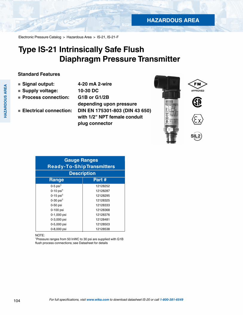
104
HAZ
ARD
OU
S AR
EA
For full specifications, visit www.wika.com to download datasheet IS-20 or call 1-800-381-6549
Electronic Pressure Catalog > Hazardous Area > IS-21, IS-21-F
Type IS-21 Intrinsically Safe Flush Diaphragm Pressure TransmitterStandard Features
Signal output: 4-20 mA 2-wire Supply voltage: 10-30 DC Process connection: G1B or G1/2B depending upon pressure Electrical connection: DIN EN 175301-803 (DIN 43 650) with 1/2" NPT female conduit plug connector
NOTE:1Pressure ranges from 50 InWC to 30 psi are supplied with G1B flush process connections; see Datasheet for details
Gauge RangesReady-To-ShipTransmitters
Description Range Part #
0-5 psi1 121282520-10 psi1 12128287 0-15 psi1 12128295 0-30 psi1 121283250-50 psi 121283330-100 psi 121283680-1,000 psi 121283760-3,000 psi 121284810-5,000 psi 121285030-8,000 psi 12128538
HAZARDOUS AREA

105
HAZARD
OU
S AREA
Electronic Pressure Catalog > Hazardous Area > IS-21, IS-21-F
For full specifications, visit www.wika.com to download datasheet IS-20 or call 1-800-381-6549
HAZARDOUS AREA
IS-21 Smart Codes for Custom Order Configurations Field no. Code Feature
Type S Standard version 1 F Field case / integral junction box Unit P psi N InWC 3 psi absolute (from 15 psi to 250 psi absolute) 2 ? Other - please specify Pressure range CA -30 inHg ... 0 CD -30 inHg ... 30 psi CF -30 inHg ... 60 psi CH -30 inHg ... 100 psi CK -30 inHg ... 160 psi CL -30 inHg ... 200 psi GG 0 InWC ... 50 InWC GU 0 InWC ... 100 InWC CN 0 psi ... 5 psi CP 0 psi ... 10 psi BC 0 psi ... 15 psi (0 psi ... 15 psi absolute) CQ 0 psi ... 25 psi (0 psi ... 25 psi absolute) BD 0 psi ... 30 psi DA 0 psi ... 50 psi (0 psi ... 50 psi absolute) BE 0 psi ... 60 psi BF 0 psi ... 100 psi (0 psi ... 100 psi absolute) BG 0 psi ... 160 psi BH 0 psi ... 200 psi DG 0 psi ... 250 psi (0 psi ... 250 psi absolute) BI 0 psi ... 300 psi DI 0 psi ... 500 psi BL 0 psi ... 600 psi DJ 0 psi ... 750 psi BN 0 psi ... 1,000 psi BO 0 psi ... 1,500 psi BP 0 psi ... 2,000 psi BQ 0 psi ... 3,000 psi BS 0 psi ... 5,000 psi DS 0 psi ... 8,000 psi 3 ?3 Other-up to maximum specified pressure range
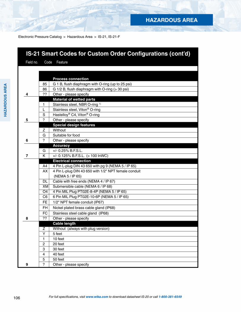
106
HAZ
ARD
OU
S AR
EA
Electronic Pressure Catalog > Hazardous Area > IS-21, IS-21-F
For full specifications, visit www.wika.com to download datasheet IS-20 or call 1-800-381-6549
HAZARDOUS AREA
IS-21 Smart Codes for Custom Order Configurations (cont’d) Field no. Code Feature
Process connection 85 G 1 B, flush diaphragm with O-ring (up to 25 psi) 86 G 1/2 B, flush diaphragm with O-ring (> 30 psi) 4 ?? Other - please specify Material of wetted parts 1 Stainless steel, NBR O-ring 1) L Stainless steel, Viton® O-ring S Hastelloy® C4, Viton® O-ring 5 ? Other - please specify Special design features Z Without G Suitable for food 6 ? Other - please specify Accuracy G +/- 0.25% B.F.S.L. 7 K +/- 0.125% B.F.S.L. (> 100 InWC) Electrical connection A4 4 Pin L-plug DIN 43 650 with pg 9 (NEMA 5 / IP 65) AX 4 Pin L-plug DIN 43 650 with 1/2" NPT female conduit (NEMA 5 / IP 65) DL Cable with free ends (NEMA 4 / IP 67) XM Submersible cable (NEMA 6 / IP 68) O4 4 Pin MIL Plug PT02E-8-4P (NEMA 5 / IP 65) C6 6 Pin MIL Plug PT02E-10-6P (NEMA 5 / IP 65) FE 1/2" NPT female conduit (IP67) FH Nickel plated brass cable gland (IP68) FC Stainless steel cable gland (IP68) 8 ?? Other - please specify Cable length Z Without (always with plug version) Y 5 feet 1 10 feet 2 20 feet 3 30 feet 4 40 feet 5 50 feet 9 ? Other - please specify

107
HAZARD
OU
S AREA
Electronic Pressure Catalog > Hazardous Area > IS-21, IS-21-F
For full specifications, visit www.wika.com to download datasheet IS-20 or call 1-800-381-6549
HAZARDOUS AREA
1 2 3 4 5 6 7 8 9 10 11 12 13 14 15*Order Code:
IS-21 - - - - A -
*Additional order details
NOTES:1) Not available with cooling element option (Field 10, Code C)2) Only available with MIL Plug version (Field 8, Codes 04 and C6) 3) Only available in IP68 version4) Maximum media temperature is -4 ... +176o F (-20 ... +80o C) (Field 10, Code U)
IS-21 Smart Codes for Custom Order Configurations (cont’d) Field no. Code Feature
Temperature range of medium U -20 ... +80 °C (-4 ... +176 °F) 10 C -20 ... +150 °C (-4 ... +302 °F) with cooling element SIL2 SIL2 Z Without 11 S SIL2 according to IEC61508 / IEC61511 Approvals 1 EEx ia I M1 + 1/2G, 2G incl. FM, CSA & ATEX A EEx ia II C T6 1/2G, 2G per ATEX incl. FM & CSA 2) D EEx IP6X 1/2D, 2D + 1/2 G, 2G +M1 per ATEX incl. FM and CSA 3) 4) S EEx ia II C T6 1/2G per ATEX 12 incl. FM, CSA and ship approval GL Quality certificates Z Without I NIST Certificate of Calibration (always with 0.125% accuracy) 13 ? Other - please specify Digital display Z Without 14 1 Digital display (order separately) Additional order details Z Without 15 T Additional order details
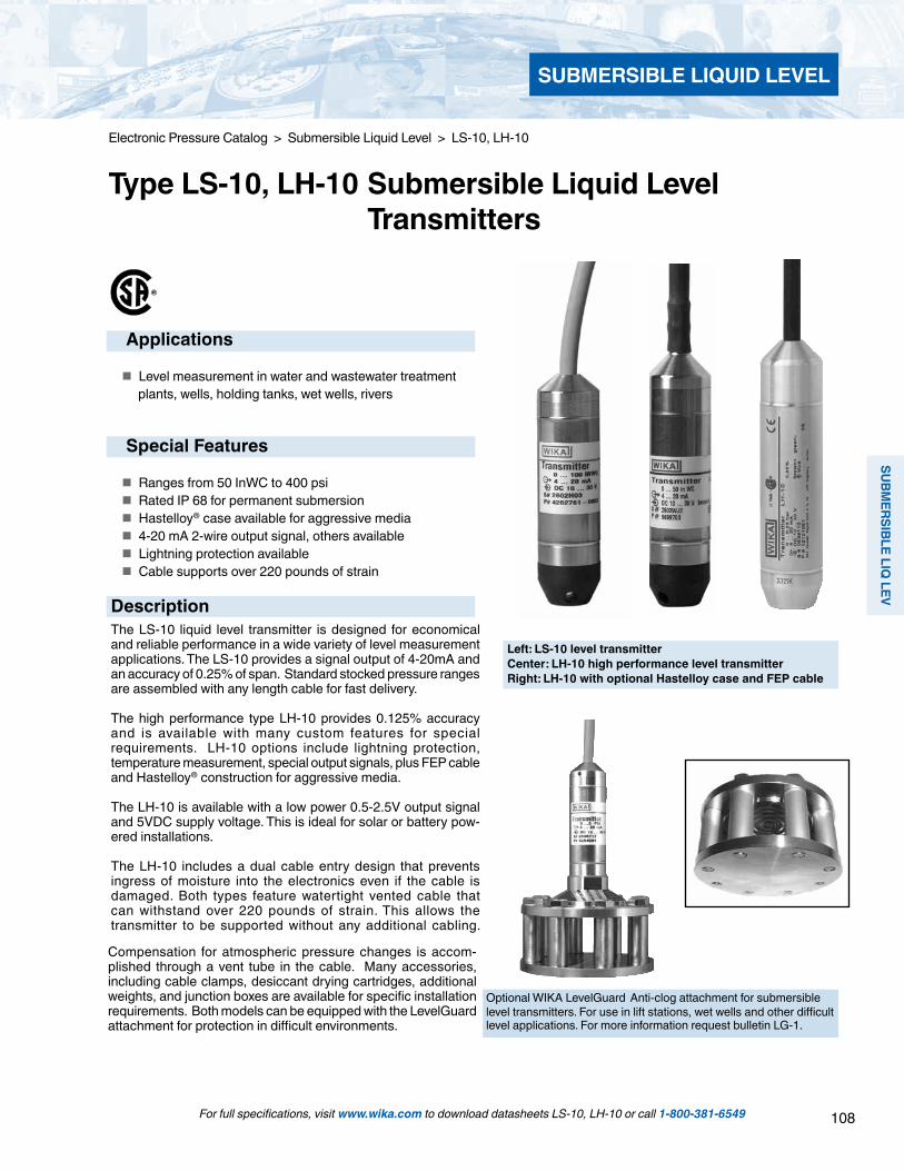
108
SUBMERSIBLE LIQ
LEV
SUBMERSIBLE LIQUID LEVEL
For full specifications, visit www.wika.com to download datasheets LS-10, LH-10 or call 1-800-381-6549
Electronic Pressure Catalog > Submersible Liquid Level > LS-10, LH-10
Type LS-10, LH-10 Submersible Liquid Level Transmitters
Left: LS-10 level transmitterCenter: LH-10 high performance level transmitterRight: LH-10 with optional Hastelloy case and FEP cable
Applications
Level measurement in water and wastewater treatment plants, wells, holding tanks, wet wells, rivers
Special Features
Ranges from 50 InWC to 400 psi Rated IP 68 for permanent submersion Hastelloy® case available for aggressive media 4-20 mA 2-wire output signal, others available Lightning protection available Cable supports over 220 pounds of strain
The LS-10 liquid level transmitter is designed for economical and reliable performance in a wide variety of level measurement applications. The LS-10 provides a signal output of 4-20mA and an accuracy of 0.25% of span. Standard stocked pressure ranges are assembled with any length cable for fast delivery.
The high performance type LH-10 provides 0.125% accuracy and is available with many custom features for special requirements. LH-10 options include lightning protection, temperature measurement, special output signals, plus FEP cable and Hastelloy® construction for aggressive media.
The LH-10 is available with a low power 0.5-2.5V output signal and 5VDC supply voltage. This is ideal for solar or battery pow-ered installations.
The LH-10 includes a dual cable entry design that prevents ingress of moisture into the electronics even if the cable is damaged. Both types feature watertight vented cable that can withstand over 220 pounds of strain. This allows the transmitter to be supported without any additional cabling.
Compensation for atmospheric pressure changes is accom-plished through a vent tube in the cable. Many accessories, including cable clamps, desiccant drying cartridges, additional weights, and junction boxes are available for specific installation requirements. Both models can be equipped with the LevelGuard attachment for protection in difficult environments.
Optional WIKA LevelGuard Anti-clog attachment for submersible level transmitters. For use in lift stations, wet wells and other difficult level applications. For more information request bulletin LG-1.
Description

109
SUBM
ERSI
BLE
LIQ
LEV
SUBMERSIBLE LIQUID LEVEL
For full specifications, visit www.wika.com to download datasheets LS-10, LH-10 or call 1-800-381-6549
Specifications Type LS-10, LH-10
Pressure rangesLS-10 or LH-10 pressure ranges 100 InWC 150 InWC 250 InWC 400 InWC 5 psi 10 psi 15 psi 25 psi 30 psi 50 psi 100 psiMaximum pressure* 30 psi 30 psi 60 psi 72 psi 30 psi 60 psi 72 psi 145 psi 145 psi 240 psi 500 psiBurst pressure** 35 psi 35 psi 70 psi 87 psi 35 psi 70 psi 87 psi 170 psi 170 psi 290 psi 600 psiLH-10 pressure ranges1) 50 InWC 160 psi 200 psi 250 psi 300 psi 400 psiMaximum pressure* 14 psi 1,160 psi 1,160 psi 1,160 psi 1,160 psi 1,160 psiBurst pressure** 29 psi 1,390 psi 1,390 psi 1,390 psi 1,390 psi 1,390 psi1) Maximum range for LH-10 with FEP cable is 150 psi
Type LS-10 Type LH-10Materials Body Stainless steel Stainless steel Hastelloy ® Pressure connection and Stainless steel Stainless steel Hastelloy ® diaphragm Protective cap PA PA Stainless steel Hastelloy ® Cable PUR (polyurethane) PUR FEP, to 150 psi maximumPower supply UB DC V 10 < UB ≤ 30 10 < UB ≤ 30
(14 ... 30 with 0 ... 10 V output signal)(5 ... 30 for battery powered operation, output signal 0.5 ... 2.5 V) 2)
Output signal 4 ... 20 mA, 2-wire 4 ... 20 mA, 2-wire0 ... 20 mA, 3-wire0 ... 5 V, 3-wire0 ... 10 V, 3-wire0.5 ... 2.5 V, 3-wirefor battery powered operation 3)
Pt 100, 4-wire; IEC 60751Other signal outputs on request
2) Power supply 5 ... 10 VDC with optional lightning protection3) Available with pressure ranges > 0 100inWC
Pt 100 RTD temperature sensor I max mA Not available 3 I mess mA Not available 1Maximum load RA Current output signal RA < (UB - 10V) / 0.02A – (0.043 Ohm x cable length in feet) Voltage output signal - RA > 100 kOhmIsolation voltage DC V 500 4) 500 4)
4) NEC Class 02 power supply (low voltage and low current max. 100 VA even in fault conditions)
Accuracy 5) % of span ≤ 0.25 (BFSL) ≤ 0.125 6) (BFSL)% of span ≤ 0.5 (limit point calibration) ≤ 0.25 6) (limit point calibration) 5) Including non-linearity, hysteresis, zero point and full scale error per IEC 61298-2 Limit point calibration method performed in vertical mounting position with pressure connection facing down.6) For pressure ranges < 0 ... 100inWC accuracy < 0.25% of span ( BFSL) . < 0.5% of span (limit point calibration)
Non-linearity % of span ≤ 0.2 (BFSL) per IE-61298-2Non-repeatability % of span ≤ 0.1 ≤ 0.11-year stability % of span ≤ 0.2 (at reference conditions) ≤ 0.2 (at reference conditions) Permissible temperature of Medium 7) +14 ... +122 °F -10 ... +50 °C +14 ... +122 °F -10 ... +50 °C
+14 ... +185 °F (-10 ... +85 °C) withFEP-cable option
Storage 7) -22 ... +176 °F -30 ... +80 °C -22 ... +176 °F -30 ... +80 °C7) Also complies with EN 50178, Tab. 7, Type C, Class 4KH Operation, 1K4 Storage, 1K3 Transport
Compensated temperature range 0 ... +50 °C +32 ... +122 °F 0 ... +50 °C +32 ... +122 °FTemperature coefficients (TC) withincompensated temperature range: Mean TC of zero % of span ≤ 0.2 / 10 K (< 0.4 for 50 InWC) Mean TC of range % of span ≤ 0.2 / 10 K ≤ 0.2 / 10 K
Electronic Pressure Catalog > Submersible Liquid Level > LS-10, LH-10
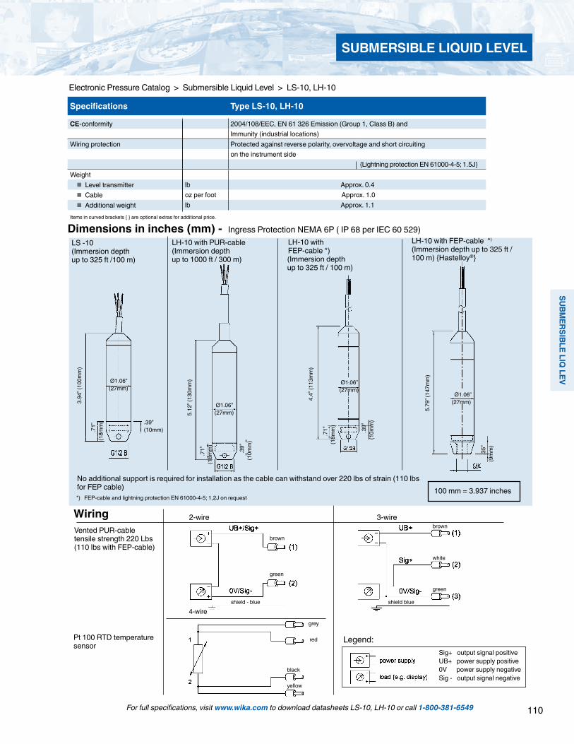
110
SUBMERSIBLE LIQ
LEV
SUBMERSIBLE LIQUID LEVEL
For full specifications, visit www.wika.com to download datasheets LS-10, LH-10 or call 1-800-381-6549
Electronic Pressure Catalog > Submersible Liquid Level > LS-10, LH-10
LH-10 with FEP-cable *)
(Immersion depth up to 325 ft / 100 m) Hastelloy®
.71”
(1
8mm
)
.
39”
(10m
m)
4.4”
(113
mm
)
.
35”
(9m
m)
5.79
” (14
7mm
)
Ø1.06” (27mm)
Ø1.06” (27mm)
Legend:Sig+ output signal positiveUB+ power supply positive0V power supply negativeSig - output signal negative
Dimensions in inches (mm) - Ingress Protection NEMA 6P ( IP 68 per IEC 60 529)
100 mm = 3.937 inches
LS -10(Immersion depth up to 325 ft /100 m)
LH-10 with FEP-cable *)
(Immersion depth up to 325 ft / 100 m)
*) FEP-cable and lightning protection EN 61000-4-5; 1,2J on request
3-wire 2-wire Vented PUR-cabletensile strength 220 Lbs(110 lbs with FEP-cable)
Wiring
brown
green
shield - blue
4-wire
Pt 100 RTD temperature sensor
grey
red
black
yellow
brown
shield blue
green
white
No additional support is required for installation as the cable can withstand over 220 lbs of strain (110 lbs for FEP cable)
LH-10 with PUR-cable(Immersion depthup to 1000 ft / 300 m)
Ø1.06” (27mm)
3.94
” (10
0mm
)
.39” (10mm)
.71”
(1
8mm
)
.71”
(1
8mm
)
.
39”
(10m
m)
5.12
” (13
0mm
)
Ø1.06” (27mm)
Specifications Type LS-10, LH-10
CE-conformity 2004/108/EEC, EN 61 326 Emission (Group 1, Class B) andImmunity (industrial locations)
Wiring protection Protected against reverse polarity, overvoltage and short circuiting on the instrument side
Lightning protection EN 61000-4-5; 1.5JWeight Level transmitter lb Approx. 0.4 Cable oz per foot Approx. 1.0 Additional weight lb Approx. 1.1
Items in curved brackets are optional extras for additional price.

111
SUBM
ERSI
BLE
LIQ
LEV
SUBMERSIBLE LIQUID LEVEL
Electronic Pressure Catalog > Submersible Liquid Level > LS-10, LH-10
For full specifications, visit www.wika.com to download datasheets LS-10, LH-10 or call 1-800-381-6549
LevelGuard Anti-clog attachment Part # 50077091
The stainless steel LevelGuard attachment must be factory installed and calibrated.
Accessories Dimensions in inches (mm)
0.28”(7 mm)
0
.43”
(11
mm
)
5.1
2”(1
30 m
m)
6
.89”
(175
mm
)
5
.12”
(130
mm
)
Cable clamp Part# 2074257The cable clamp secures the cable without bending or kinking that can damage the cable vent tube or outer jacket.
Additional weight Part# 1524399The additional weight replaces the protective cap and helps to stabilize the transmitter in turbulent conditions. Weight: approximately 1.1 lb, 316 SS.
Cable junction box Part# 2459686The cable junction box is rated NEMA 4 / IP 67 and is suitable for mounting outside tanks or shafts or inside dry control boxes. Can be wall or DIN rail mounted.
Vent tube filter Part# 7193131The optional Teflon® vent tube filter protects the vent opening and pro-tects against the entry of dirt and moisture. .
7.67" [194.82mm]
4.45" [113.03mm]
0.86" [21.84mm]
(22mm)
7.67” (195mm)
4.45” (113mm)
Desiccant drying cartridge Part # 9836700
NPT adapter Part# 1631322The 316 SS G1/2 adapter replaces the removable protective cap and converts the threads to 1/2”NPT male external, 1/4” female internal threads. Includes O-ring.
The desiccant drying cartridge helps prevent moisture buildup inside the vent tube.
1.23” (31mm)
1.81”(46mm)
1/2” NPT male
1/4” NPT femaleinternal
O-ring
3.70”(94 mm)
Conduit adapter Part# 50476114316 SS 1/2” NPT male cable conduit adapter.Must be factory installed.
1.17”29.7mm
27mm betweenflats
1/2 NPT
1.85
” (47
mm
)

112
SUBMERSIBLE LIQ
LEV
Applications
Deep well and borehole measurements Groundwater monitoring Level measurement in open bodies of water Sewage lift and pumping stations Settling ponds and rainwater basins
Special Features Slender design Adjustable turndown (option) Resistant against the harshest environmental conditions Reliable and secure by double-sealed design Titanium case for especially high resistance (option)
SUBMERSIBLE LIQUID LEVEL
For full specifications, visit www.wika.com to download datasheet LH-20 or call 1-800-381-6549
Submersible pressure transmitter model LH-20Fig. left: from stainless steelFig. right: from titanium
Description
For the most demanding measurement tasksThe model LH-20 submersible pressure transmitter has been designed for the most demanding of level measurement tasks. A slender design, highest accuracies, low temperature errors and an adjustable measuring range ensure the suita-bility of the LH-20 for all submerged level measurements.
The model LH-20 submersible pressure transmitter can adapt to countless applications and measuring media through a large number of features and options. Depend-ing on the requirements, this level probe is available with, amongst other things, a titanium case, PUR/PE/FEP cable, 0.1 % accuracy, HART, scaleability or parallel temperature output signal.
For operation in hazardous environments, the model LH-20 submersible pressure transmitter is also available in an intrin-sically safe version. For potable and fresh water applications,
a potable water conformant product variant is possible in accordance with KTW and ACS.
Hermetically sealed, robust and durableThe model LH-20 submersible pressure transmitter has been engineered for use in the harshest environments. Through a double, redundant sealing concept, it is permanently hermet-ically sealed. A robust design from stainless steel or titanium, with a spring-reinforced cable seal, ensures a long service life, even under the big mechanical loads of installation and continuous use.
Designs with the highest media resistance using FEP cable and titanium cases, along with the integrated lightning protection, guarantee the longevity of the submersible pressure transmitter even under the most adverse environ-mental influences in aggressive media, in both indoor and outdoor use.
Electronic Pressure Catalog > Submersible Liquid Level > LH-20
Type LH-20 High-Performance Submersible Liquid Level Transmitters

113
SUBM
ERSI
BLE
LIQ
LEV
SUBMERSIBLE LIQUID LEVEL
Electronic Pressure Catalog > Submersible Liquid Level > LH-20
For full specifications, visit www.wika.com to download datasheets LH-20 or call 1-800-381-6549
Measuring ranges
Relative pressure
bar Measuring range 0 ... 0.1 0 ... 0.16 0 ... 0.25 0 ...0.4 0 ... 0.6Overpressure limit 15 20 30 30 35Measuring range 0 ... 1 0 ... 1.6 0 ... 2.5 0 ... 4 0 ... 6Overpressure limit 35 50 50 65 90Measuring range 0 ... 10 0 ... 16 0 ... 25Overpressure limit 90 130 130
inWC Measuring range 0 ... 50 0 ... 100 0 ... 150 0 ... 250Overpressure limit 8,000 12,000 12,000 14,000
psi Measuring range 0 ... 5 0 ... 10 0 ... 15 0 ... 25 0 ... 50Overpressure limit 400 500 700 700 900Measuring range 0 ... 100 0 ... 160 0 ... 200 0 ... 300Overpressure limit 1,300 1,900 1,900 1,900
mH2O Measuring range 0 ... 1 0 ... 1.6 0 ... 2.5 0 ... 4 0 ... 6Overpressure limit 150 200 300 300 350Measuring range 0 ... 10 0 ... 16 0 ... 25 0 ... 40 0 ... 60Overpressure limit 350 500 500 650 900Measuring range 0 ... 100 0 ... 160 0 ... 250Overpressure limit 900 1,300 1,300
Absolute pressure
bar Measuring range 0 ... 1.6 0 ... 2.5 0 ... 4 0 ... 6 0 ... 10Overpressure limit 50 50 60 90 90Measuring range 0 ... 16 0 ... 25Overpressure limit 130 130
Output signals
Output signalStandard 4 ... 20 mAOption 4 ... 20 mA and HART signal, additional Pt100
measurement signal
Load in Ω 4 ... 20 mA:
≤ (power supply - 8 V) / 0.022 A
4 ... 20 mA and HART signal:≤ (power supply - 9.6 V) / 0.022 A
Voltage supply
Power supplyThe power supply depends on the selected output signal.
4 ... 20 mA: DC 8 ... 36 V 4 ... 20 mA and HART signal: DC 9.6 ... 36 V
When being operated in Ex areas, the submersible pressure transmitter must be powered via an Ex isolated barrier.For Ex isolated barrier see "Accessories"
Additional Pt100 measuring element
The HART version has an additional Pt100 measuring element for measuring the temperature of the medium.
Specifications: Pt100 per DIN EN 60751 Measuring range -50 ... +100 °C Resolution of 1 °K
The given measuring ranges are also available in mbar, kPA and MPa.
114
SUBMERSIBLE LIQ
LEV
SUBMERSIBLE LIQUID LEVEL
For full specifications, visit www.wika.com to download datasheet LH-20 or call 1-800-381-6549
Electronic Pressure Catalog > Submersible Liquid Level > LH-20
Accuracy data
Non-linearity at reference conditions
Non-linearityStandard ≤ ±0.2 % of spanOption ≤ ±0.1 % of span
By setting a turndown of greater than 5:1, the non-linearity is decreased.
Determined using the limit point method in accordance to IEC 60770
Temperature error of the zero point in the temperature range 0 ... 80 °C
at non-linearity ≤ 0.2 % of span- Standard, without turndown ≤ 0.15 % of span/10 K- Turndown ≤ 5:1 ≤ 0.20 % of span/10 K- Turndown > 5:1 ≤ 0.25 % of span/10 K
at non-linearity ≤ ± 0.1 % of span- Standard, without turndown ≤ 0.05 % of span/10 K- Turndown ≤ 5:1 ≤ 0.10 % of span/10 K- Turndown > 5:1 ≤ 0.15 % of span/10 K
Long-term drift≤ 0.1 % of span/year
Settling time (0 ... 63 %)Depending on the output signal the following settling times apply:
4 ... 20 mA: 100 ms 4 ... 20 mA, HART signal: 200 ms
Reference conditions
Temperature15 ... 25 °C
Atmospheric pressure860 ... 1,060 mbar
Humidity45 ... 75 % relative
Mounting positionCalibrated in vertical mounting position with pressure connection facing downwards.
Scalability (turndown)The HART version enables turndown to be set.
It is recommended that turndown is not set to over 5:1, since the accuracy can decrease dependant on the scaling.
Operating conditions
Ingress protection (per IEC 60529)IP 68
Vibration resistance (per IEC 60068-2-6)4 g (at 5 ... 100 Hz)
Lightning protectionNominal discharge current ≥ 5 kA, response time < 25 ns
Explosion protection (optional)The model LH-20 submersible pressure transmitter is avail-able with the following Ex approvals, which can be ordered separately.
Approval ATEX II 1G, 2G Ex ia IIC T6IECEx ia IIC T6
Temperatures
for use without explosion protection
The permissible temperature ranges are dependent on the cable material used:
- Medium- PE cable: - 40 ... +60 °C- PUR cable: - 40 ... +80 °C- FEP cable: - 40 ... +80 °C
- Ambient- PE cable: - 40 ... +60 °C- PUR cable: - 40 ... +85 °C- FEP cable: - 40 ... +85 °C
- Storage- PE cable: - 40 ... +80 °C- PUR cable: - 40 ... +80 °C- FEP cable: - 40 ... +80 °C
for use as Category 1G equipment- Ambient
- Temperature class T6: - 20 ... +50 °C- Temperature class T1 ... T5: - 20 ... +60 °C
115
SUBM
ERSI
BLE
LIQ
LEV
SUBMERSIBLE LIQUID LEVEL
Electronic Pressure Catalog > Submersible Liquid Level > LH-20
For full specifications, visit www.wika.com to download datasheets LH-20 or call 1-800-381-6549
Cable outlet
U+ brownU- blueShield black sheathed cable
Pt100 measuring element (4-wire connection)
1 white
2 yellow
3 red
4 black
Materials (wetted)
CaseStandard Stainless steel 316LOption Titan
Cable materialStandard PUROption 1 PEOption 2 FEP
Sealing material 1)
Standard FKMOption EPDM
1) The model LH-20 is double sealed behind the sensor.
Additional weightStandard Stainless steel 316LOption Titan
SensorCeramic Al2O3 96 %
Approvals, directives and certificates
Approvals and certificatesOn request, the submersible pressure transmitter can be supplied with the following approvals and certificates:
Available approvalsATEX (explosion protection in accordance with ATEX)IECEx (explosion protection in accordance with IECEx)GL (Germanischer Lloyd)
Available certificatesDrinking water declaration of conformity in accordance with KTW and ACSTest certificate 1)
1) The test certificate documents the product-specific instrument specifications and include a detailed listing of the individual measured values of the acceptance test.
CE conformity Outputsignal 4 ... 20 mA:
EMC directive 2004/108/EC, EN 61326 emission (group 1, class B) and interference immunity (industrial application)
Outputsignal 4 ... 20 mA and HART signal:EMC directive 2004/108/EC, EN 61326 emission (group 1, class A) and interference immunity (industrial application)
ATEX 94/9/EG (option)
Electrical connections
Reverse polarity protectionU+ vs. U-
Overvoltage protectionsee lightning protection under "Operating conditions"
Cable lengthsCable length to customer requirements, freely selectable
Connection diagrams
Process connections
The model LH-20 is available in two process connection variants:
Process connectionStandard M14 x 1 with protective capOption Flush measuring cell
1
2
3
4
for use as Category 2G equipment- Ambient
- Temperature class T6: -40 ... +66 °C- Temperature class T1 ... T5: -40 ... +80 °C
Maximum tensile force on the cable1,200 N
Weight Submersible pressure transmitter: approx. 370 g Cable: approx. 100 g/m Additional weight (accessories): approx. 350 g

116
SUBMERSIBLE LIQ
LEV
SUBMERSIBLE LIQUID LEVEL
For full specifications, visit www.wika.com to download datasheet LH-20 or call 1-800-381-6549
Electronic Pressure Catalog > Submersible Liquid Level > LH-20
with flush measuring cell with M14 x 1 process connection and protection cap
For a particularly high resistance against aggressive media, the model LH-20 submersible pressure transmitter is available with a titanium case.
This exceptionally high-quality material enables the submersible pressure transmitter to be used under the most adverse conditions.The highly chemically-resistant titanium design ensures a long service life, even in aggressive media and the most demanding applications.
The additional weight, available as an accessory, is also obtainable in titanium.
Titanium for especially high resistance (option)
Dimensions in mm
Submersible pressure transmitter model LH-20

117
SUBM
ERSI
BLE
LIQ
LEV
SUBMERSIBLE LIQUID LEVEL
Electronic Pressure Catalog > Submersible Liquid Level > LH-20
For full specifications, visit www.wika.com to download datasheets LH-20 or call 1-800-381-6549
Description Order number
Cable strain relief clampThe cable strain relief clamp enables easy and secure mechanical fastening of the submersible pressure transmitter’s cable at the meas-uring point. It acts as a guide for the cable, in order to avoid mechanical damage and to reduce the tensile stress.
14052336
Additional weightThe additional weight increases the dead weight of the submersible pressure transmitter. It simplifies the lowering into monitoring wells, narrow shafts and deep wells. It effectively reduces negative environmental influences on the measuring result from the measured medium (e.g. turbulent flow).
The additional weight is available in two variants: Stainless steel 316L, approx. 350 g, length 120 mm Titanium, approx. 350 g, length 214.5 mm
It is recommended that the design of the additional weight is selected in line with the case material of the submersible pressure transmitter.
14052322 (316L)14052330 (Titanium)
Terminal boxThe terminal box, with IP 67 ingress protection and watertight ventilation element, provides a moisture-free electrical termination for the submers-ible pressure transmitter. It should be mounted in a dry environment, outside any shafts or vessels, or directly in the switch cabinet.
14052339
Ex isolated barrierEx isolated barrier, power supply DC 20 ... 32 V, output: max. DC 25.4 V, max. 88.2 mA
2341268
Display module DIH52 and DIH625-digit display, 20-segment bargraph, without separate power supply, with additional HART® functionality. Automatic adjustment of measur-ing range and span.Secondary-master functionality: Setting the measuring range and unit of the connected transmitter using HART® standard commands possible. Optionally explosion protection per ATEX.
on request
HART modem with USB, RS-232 or Bluetooth interfaceFor scaling the measuring range using a PC via the HART protocol, a HART modem with USB, RS-232 or Bluetooth interface is available. The modem communicates with all registered HART field devices and can be used with the most popular HART compatible software programs.
7957522 (RS-232 interface)11025166 (USB interface)11364254 (Bluetooth interface)
Ordering informationModel / Measuring range / Output signal / Accuracy / Cable material / Cable length / Case / Process connection / Sealing / Approval / Certificate / Accessories
Accessories
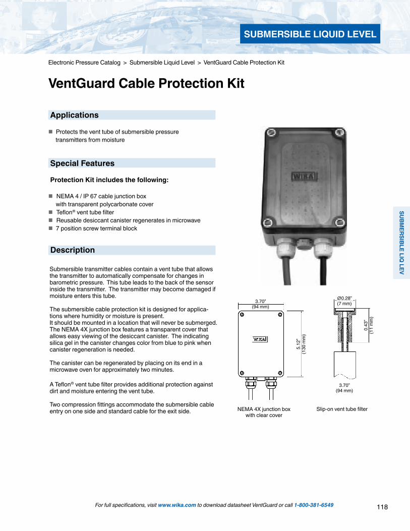
118
SUBMERSIBLE LIQ
LEV
SUBMERSIBLE LIQUID LEVEL
Description
Applications
Protects the vent tube of submersible pressure transmitters from moisture
Special Features
Protection Kit includes the following:
NEMA 4 / IP 67 cable junction box with transparent polycarbonate cover Teflon® vent tube filter Reusable desiccant canister regenerates in microwave 7 position screw terminal block
Submersible transmitter cables contain a vent tube that allows the transmitter to automatically compensate for changes in barometric pressure. This tube leads to the back of the sensor inside the transmitter. The transmitter may become damaged if moisture enters this tube.
The submersible cable protection kit is designed for applica-tions where humidity or moisture is present.It should be mounted in a location that will never be submerged. The NEMA 4X junction box features a transparent cover that allows easy viewing of the desiccant canister. The indicating silica gel in the canister changes color from blue to pink when canister regeneration is needed.
The canister can be regenerated by placing on its end in a microwave oven for approximately two minutes.
A Teflon® vent tube filter provides additional protection against dirt and moisture entering the vent tube.
Two compression fittings accommodate the submersible cable entry on one side and standard cable for the exit side. NEMA 4X junction box
with clear coverSlip-on vent tube filter
Electronic Pressure Catalog > Submersible Liquid Level > VentGuard Cable Protection Kit
VentGuard Cable Protection Kit
3.70”(94 mm)
∅0.28”(7 mm)
5.12
”(1
30 m
m)
3.70”(94 mm)
0.43
”(1
1 m
m)
For full specifications, visit www.wika.com to download datasheet VentGuard or call 1-800-381-6549
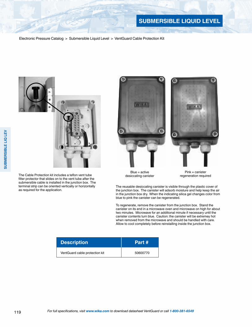
119
SUBM
ERSI
BLE
LIQ
LEV
SUBMERSIBLE LIQUID LEVEL
For full specifications, visit www.wika.com to download datasheet VentGuard or call 1-800-381-6549
Electronic Pressure Catalog > Submersible Liquid Level > VentGuard Cable Protection Kit
The reusable desiccating canister is visible through the plastic cover of the junction box. The canister will adsorb moisture and help keep the air in the junction box dry. When the indicating silica gel changes color from blue to pink the canister can be regenerated.
To regenerate, remove the canister from the junction box. Stand the canister on its end in a microwave oven and microwave on high for about two minutes. Microwave for an additional minute if necessary until the canister contents turn blue. Caution: the canister will be extremey hot when removed from the microwave and should be handled with care. Allow to cool completely before reinstalling inside the junction box.
The Cable Protection kit includes a teflon vent tube filter protector that slides on to the vent tube after the submersible cable is installed in the junction box. The terminal strip can be oriented vertically or horizontally as required for the application.
Blue = active desiccating canister
Pink = canister regeneration required
Description Part #
VentGuard cable protection kit 50600770
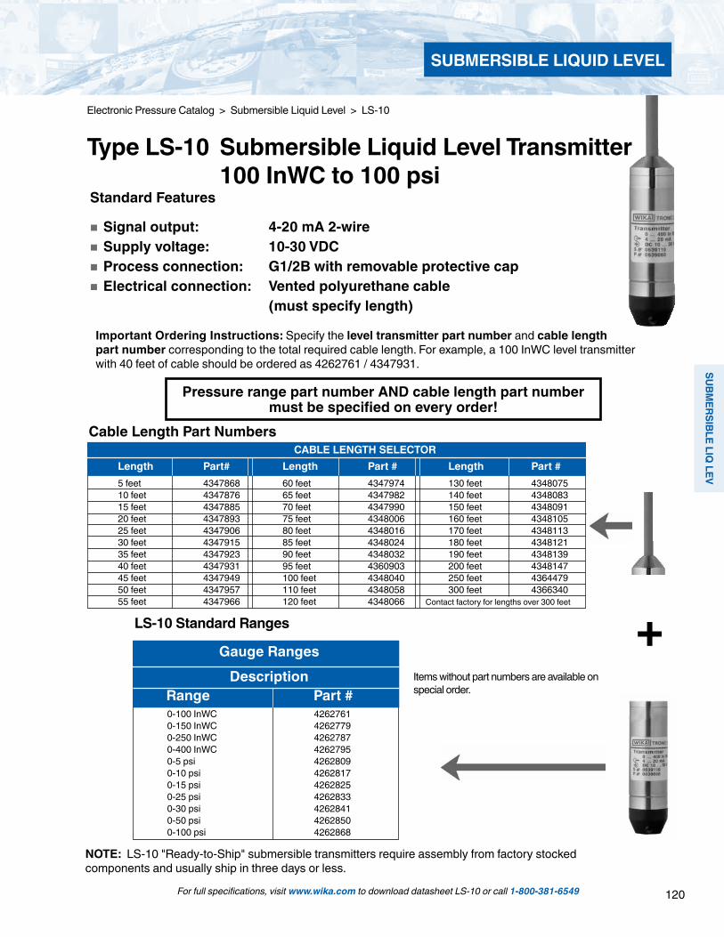
120
SUBMERSIBLE LIQ
LEV
SUBMERSIBLE LIQUID LEVEL
For full specifications, visit www.wika.com to download datasheet LS-10 or call 1-800-381-6549
Standard Features
Signal output: 4-20 mA 2-wire Supply voltage: 10-30 VDC Process connection: G1/2B with removable protective cap Electrical connection: Vented polyurethane cable (must specify length)
Important Ordering Instructions: Specify the level transmitter part number and cable length part number corresponding to the total required cable length. For example, a 100 InWC level transmitter with 40 feet of cable should be ordered as 4262761 / 4347931.
CABLE LENGTH SELECTOR Length Part# Length Part # Length Part # 5 feet 4347868 60 feet 4347974 130 feet 4348075 10 feet 4347876 65 feet 4347982 140 feet 4348083 15 feet 4347885 70 feet 4347990 150 feet 4348091 20 feet 4347893 75 feet 4348006 160 feet 4348105 25 feet 4347906 80 feet 4348016 170 feet 4348113 30 feet 4347915 85 feet 4348024 180 feet 4348121 35 feet 4347923 90 feet 4348032 190 feet 4348139 40 feet 4347931 95 feet 4360903 200 feet 4348147 45 feet 4347949 100 feet 4348040 250 feet 4364479 50 feet 4347957 110 feet 4348058 300 feet 4366340 55 feet 4347966 120 feet 4348066 Contact factory for lengths over 300 feet
+Gauge Ranges
Description Range Part #
0-100 InWC 42627610-150 InWC 42627790-250 InWC 42627870-400 InWC 42627950-5 psi 42628090-10 psi 42628170-15 psi 42628250-25 psi 42628330-30 psi 42628410-50 psi 42628500-100 psi 4262868
NOTE: LS-10 "Ready-to-Ship" submersible transmitters require assembly from factory stocked components and usually ship in three days or less.
Pressure range part number AND cable length part number must be specified on every order!
Cable Length Part Numbers
LS-10 Standard Ranges
Items without part numbers are available on special order.
Electronic Pressure Catalog > Submersible Liquid Level > LS-10
Type LS-10 Submersible Liquid Level Transmitter 100 InWC to 100 psi
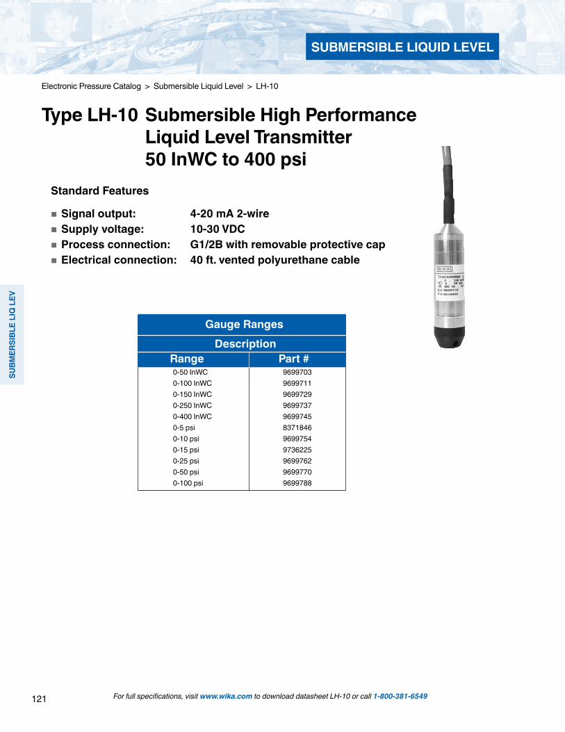
121
SUBM
ERSI
BLE
LIQ
LEV
SUBMERSIBLE LIQUID LEVEL
For full specifications, visit www.wika.com to download datasheet LH-10 or call 1-800-381-6549
Gauge Ranges Description Range Part #
0-50 InWC 96997030-100 InWC 96997110-150 InWC 96997290-250 InWC 96997370-400 InWC 96997450-5 psi 8371846 0-10 psi 96997540-15 psi 97362250-25 psi 96997620-50 psi 96997700-100 psi 9699788
Standard Features
Signal output: 4-20 mA 2-wire Supply voltage: 10-30 VDC Process connection: G1/2B with removable protective cap Electrical connection: 40 ft. vented polyurethane cable
Electronic Pressure Catalog > Submersible Liquid Level > LH-10
Type LH-10 Submersible High Performance Liquid Level Transmitter 50 InWC to 400 psi
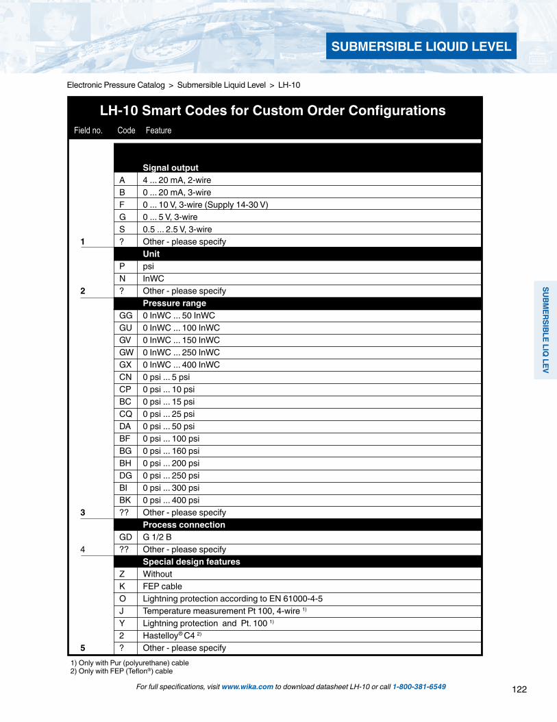
122
SUBMERSIBLE LIQ
LEV
SUBMERSIBLE LIQUID LEVEL
For full specifications, visit www.wika.com to download datasheet LH-10 or call 1-800-381-6549
Electronic Pressure Catalog > Submersible Liquid Level > LH-10
1) Only with Pur (polyurethane) cable2) Only with FEP (Teflon®) cable
LH-10 Smart Codes for Custom Order Configurations Field no. Code Feature
Signal output A 4 ... 20 mA, 2-wire B 0 ... 20 mA, 3-wire F 0 ... 10 V, 3-wire (Supply 14-30 V) G 0 ... 5 V, 3-wire S 0.5 ... 2.5 V, 3-wire 1 ? Other - please specify Unit P psi N InWC 2 ? Other - please specify Pressure range GG 0 InWC ... 50 InWC GU 0 InWC ... 100 InWC GV 0 InWC ... 150 InWC GW 0 InWC ... 250 InWC GX 0 InWC ... 400 InWC CN 0 psi ... 5 psi CP 0 psi ... 10 psi BC 0 psi ... 15 psi CQ 0 psi ... 25 psi DA 0 psi ... 50 psi BF 0 psi ... 100 psi BG 0 psi ... 160 psi BH 0 psi ... 200 psi DG 0 psi ... 250 psi BI 0 psi ... 300 psi BK 0 psi ... 400 psi 3 ?? Other - please specify Process connection GD G 1/2 B 4 ?? Other - please specify Special design features Z Without K FEP cable O Lightning protection according to EN 61000-4-5 J Temperature measurement Pt 100, 4-wire 1) Y Lightning protection and Pt. 100 1) 2 Hastelloy® C4 2) 5 ? Other - please specify

123
SUBM
ERSI
BLE
LIQ
LEV
SUBMERSIBLE LIQUID LEVEL
For full specifications, visit www.wika.com to download datasheet LH-10 or call 1-800-381-6549
Electronic Pressure Catalog > Submersible Liquid Level > LH-10
1 2 3 4 5 6 7 8 9 *LH-10 - - - - -
*Additional order details
Order Code:
LH-10 Smart Codes for Custom Order Configurations (cont’d) Field no. Code Feature
Cable Y 5 feet 1 10 feet 2 20 feet 3 30 feet 4 40 feet 5 50 feet 6 ? Other Quality certificates 7 Z Without Digital display 8 Z Without Additional order details Z Without 9 T Additional order details

124
SUBMERSIBLE LIQ
LEV
SUBMERSIBLE LIQUID LEVEL
For full specifications, visit www.wika.com to download datasheet LH-20 or call 1-800-381-6549
Electronic Pressure Catalog > Submersible Liquid Level > LH-20
LH-20 Smart Codes for Custom Order Configurations Field no. Code Feature
Unit N inWC P psi 1 ? Other - please specify Pressure reference G Gauge A Absolute (not with inWC ranges) 2 ? Other - please specify Pressure range 212 0 InWC ... 50 InWC 225 0 InWC ... 100 InWC 237 0 InWC ... 150 InWC 262 0 InWC ... 250 InWC 234 0 psi ... 5 psi 269 0 psi ... 10 psi 310 0 psi ... 15 psi 317 0 psi ... 25 psi 0 psi ... 25 psia 335 0 psi ... 50 psi 0 psi ... 50 psia 369 0 psi ... 100 psi 0 psi ... 100 psia 411 0 psi ... 160 psi 0 psi ... 160 psia 414 0 psi ... 200 psi 0 psi ... 200 psia 421 0 psi ... 300 psi 0 psi ... 300 psia 3 ??? Other - please specify Cable Material A PUR (Polyurethane) B FEP (Fluorinated Ethylene Proplyene) 4 C PE (Polyethylene) Unit of Cable Length F Feet 5 ? Other - please specify Cable Length PUR per foot price FEP per foot price PE per foot price Cable length to nearest foot 6 (Example: 40 feet = 0040) Signal Output A 4 ... 20 mA 2-wire 7 R 4 ... 20 + Hart + PT 100

125
SUBM
ERSI
BLE
LIQ
LEV
SUBMERSIBLE LIQUID LEVEL
For full specifications, visit www.wika.com to download datasheet LH-20 or call 1-800-381-6549
Electronic Pressure Catalog > Submersible Liquid Level > LH-20
LH-20 Smart Codes for Custom Order Configurations (continued) Field no. Code Feature
AccuracyM ± 0.1% B.F.S.L.
8 P ± 0.05 B.F.S.L.Housing
S Stainless steel9 T Titanium
ApprovalsA ATEXI IECEXZ Without
10 ? Other - please specifyProtection Type
E EX ia (intrinsic safety)Z Without
11 ? OtherAtmosphere
GA Gas Zone 0 and 1 (1G, 2G) (With ATEX)GB Gas Zone 0 (1G) with (IECEX)ZZ Without
12 ?? OtherOther Approvals
Z WithoutG Ship approval (GL)
13 ? OtherPotable Water Conformance Certificate
Z Without14 K KTW, ACS
CertificateZ Without
15 K With test protocolsProcess Connection
LS M14 x 1 protective capLT Flush diaphragm
16 ?? OtherSensor seal material
K Dual FKM (VP2 / A)17 E Dual EPDM (A+P 75.5 / KW75F)
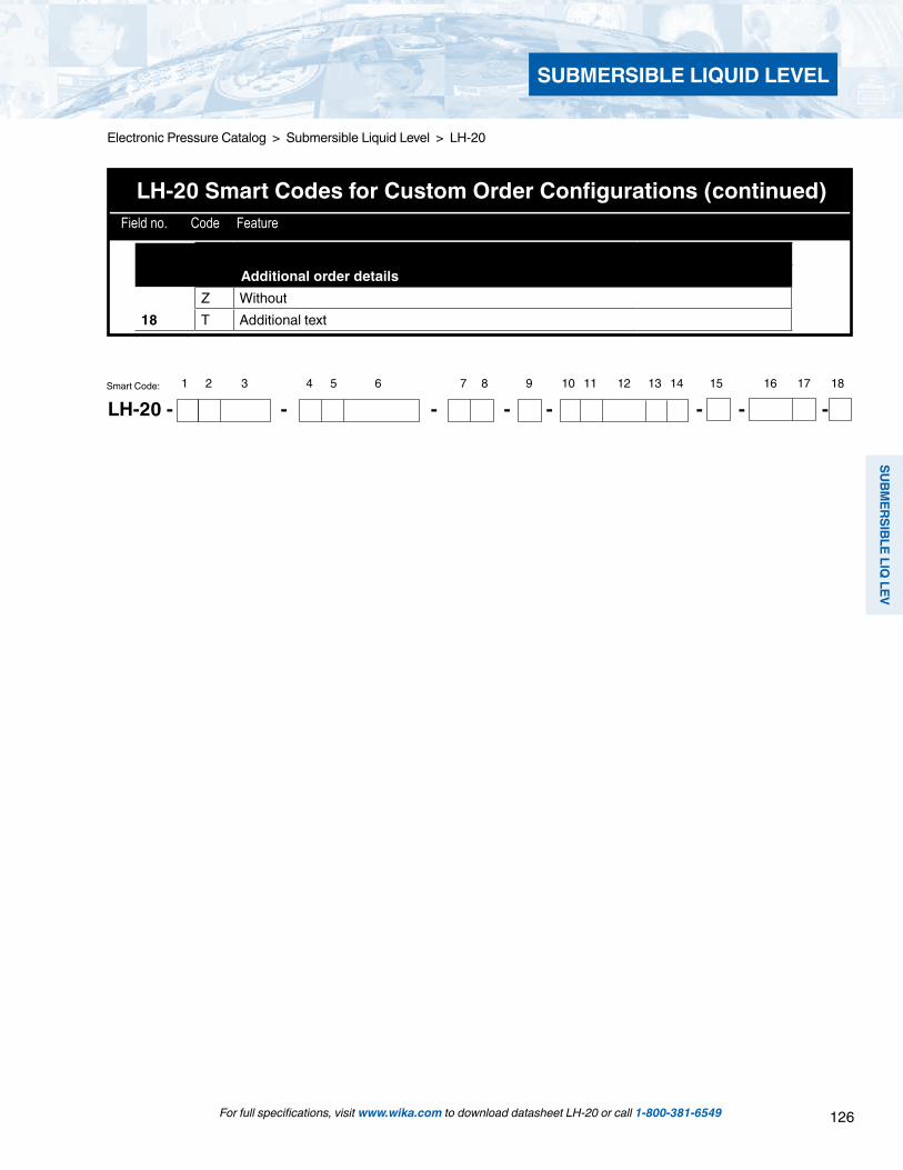
126
SUBMERSIBLE LIQ
LEV
SUBMERSIBLE LIQUID LEVEL
LH-20 Smart Codes for Custom Order Configurations (continued) Field no. Code Feature
Additional order detailsZ Without
18 T Additional text
1 2 3 4 5 6 7 8 9 10 11 12 13 14 15 16 17 18Smart Code:
LH-20 - - - - - - - -
For full specifications, visit www.wika.com to download datasheet LH-20 or call 1-800-381-6549
Electronic Pressure Catalog > Submersible Liquid Level > LH-20

127
SUBM
ERSI
BLE
LIQ
LEV
SUBMERSIBLE LIQUID LEVEL
LH-10 Smart Codes for Custom Order Configurations
For full specifications, visit www.wika.com to download datasheet IL-10 or call 1-800-381-6549
Electronic Pressure Catalog > Submersible Liquid Level > IL-10
Type IL-10 Intrinsically Safe Submersible Liquid Level Transmitter for Hazardous Environments
Optional WIKA LevelGuard Anti-clog attachment for submersible level transmitters. For use in lift stations, wet wells and other difficult level applications.
Fig. Intrinsically safe IL-10 level transmitter
Applications
Level measurement in hazardous areas Refineries Distilling equipment Painting plants Filling equipment for combustible gases Overfilling systems on tank vehicles, bore holes, waste
water plants (biogases from sewage), etc.
Special Features
Pressure ranges from 50 InWC to 400 psi Ex- protection EEx ia I/II C T6 according to ATEX Applicable in all hazardous environments:
Gases and vapor: Zone 0, Zone 1 and Zone 2 Dusts: Zone 20, Zone 21 and Zone 22
Cable supports over 220 pounds of strain Ingress protection IP 68 for submersion to 1000 feet
Description
The IL-10 intrinsically safe level transmitter is designed for use in a wide variety of level measurement applications. The IL-10 provides a BFSL accuracy better than 0.25% of span and an output signal of 4-20mA.
The IL-10 has FM, ATEX and CSA approvals for installation in hazardous areas when used with the appropriate intrinsically safe zener barrier. The cable can withstand up to 220 pounds of strain, also, no additional cable support is required.
The IL-10 includes a dual cable entry design that prevents ingress of moisture into the electronics even if the cable‘s outer jacket is damaged. Compensation for changes in barometric pressure is accomplished through a vent tube in the cable. Many accessories, including cable clamps, drying cartridges and junction boxes are available for specific instal-lation requirements.

128
SUBMERSIBLE LIQ
LEV
SUBMERSIBLE LIQUID LEVEL
For full specifications, visit www.wika.com to download datasheet IL-10 or call 1-800-381-6549
Electronic Pressure Catalog > Submersible Liquid Level > IL-10
Specifications Type IL-10Pressure ranges 100 InWC 150 InWC 250 InWC 400 InWC 5 psi 10 psi 15 psi 25 psi 30 psi 50 psi 100 psiOver-pressure safety 30 psi 30 psi 60 psi 72 psi 30 psi 60 psi 72 psi 145 psi 145 psi 240 psi 500 psiBurst pressure 35 psi 35 psi 70 psi 87 psi 35 psi 70 psi 87 psi 170 psi 170 psi 290 psi 600 psiMaterials Wetted part » Cable PUR FEP up to 10 bar » Protection cap Stainless steel Hastelloy® Case Stainless steel Hastelloy® Internal transmission fluid Synthetic oilPower supply UB UB in VDC 10 ... 30Signal output and 4 ... 20 mA, 2-wire maximum ohmic load RA RA in Ohm RA ≤ (UB – 10 V) / 0.02 A - (0.043Ω x cable length in feet)Dielectric strength Insulation complies with EN 50020, 6.4, 12Accuracy % of span ≤ 0.25 0.125 1) (BFSL)
% of span ≤ 0.5 2) 0.25 1) 2) 1) Accuracy for pressure ranges > 0.25 bar2) Including non-linearity, hysteresis, zero point and full scale error (corresponds to error of measurement per IEC 61298-2)Adjusted in vertical mounting position with lower pressure connection
Non-linearity % of span ≤ 0.2 (BFSL) according to IEC 61298-2Non-repeatability % of span ≤ 0.11-year stability % of span ≤ 0.2 (at reference conditions) Permissible temperature of Medium 3) 4) 5) -14 ... +140 °F -10 ... +60 °C
-14 ... +185 °F with FEP-cable -10 ... +85 °C with FEP-cable Storage 3) -14 ... +140 °F -10 ... +60 °C
3) Also complies with EN 50178, Tab. 7, Operation (C) 4K4H, Storage (D) 1K4, Transport (E) 2K34) Other temperature ranges are possible, depending on the electrical connection; see EC-type examination certificate and table page 4.
Compensated temp. range 32 ... +122 °F 0 ... +50 °CTemperature coefficients withincompensated temp range Mean TC of zero % of span ≤ 0.2 / 10 K ( < 0.4 for pressure ranges ≤ 50 InWC) Mean TC of range % of span ≤ 0.2 / 10 KCE-conformity EMC directive 2004/108/EEC, EN 61 326 Emission (Group 1, Class B) and
Immunity (industrial locations) ATEX-Directive ATEX of equipment intended for use in potentially explosive atmospheres
94/9/EC
Ex-protection ATEX Category 5) 1G (IIA), 1/2G, 2G (IIA), 1D, 1/2D, 2D, M1, M2Ignition protection type EEx ia I/II C T4, EEx ia I/II C T5, EEx ia I/II C T6
5) Read the operating conditions and safety-relevant data in the EC-type examination certificate in any case (DMT 00 ATEX E 045 X)
Ex-protection FM, CSA Class I, II and IIIIgnition protection type Intrinsic safe Class I, II, III Division 1,
Group A, B, C, D, E, F, G and Class I, Zone 0 AEx ia II CApproval German Lloyd GL Environmental Category C, F, EMC 1HF-immunity V/m 10BURST KV 4Wiring protection Short-circuit proofness Sig+ towards UB- Reverse polarity protection UB+ towards UB-Weight lb Approx. 0.1 » Cable oz. per ft. Approx. 1.0
Items in curved brackets are optional extras for additional price.

129
SUBM
ERSI
BLE
LIQ
LEV
SUBMERSIBLE LIQUID LEVEL
For full specifications, visit www.wika.com to download datasheet IL-10 or call 1-800-381-6549
Electronic Pressure Catalog > Submersible Liquid Level > IL-10 Dimensions in mm
Wiring details
Vented PUR-cable,max tensile strength of 1000 N(immersion depth up to 300 m)
FEP-cablemax tensile strength of 500 N(immersion depth up to 100 m)
Ingress Protection IP 68 per IEC 60529.
When mounting, no additional strain relief is required.For installation and safety instructions see the operating instructions for this product.
FEP-cable max tensile strength of 500 N(immersion depth up to 100 m),Hastelloy®
Electrical connectionsPermissible temperature ranges depending on electrical connections; see table page 4.
Vented cableconductor cross section 0.25 mm 2, AWG 24 with end splices, conductor outer diameter 7.5 mm brown
green
2-wire
Legend:
Non hazardous area
Hazardous (classified area)
shield - blue
Line transformer
Load (e.g. display)
Power supply

130
SUBMERSIBLE LIQ
LEV
SUBMERSIBLE LIQUID LEVEL
For full specifications, visit www.wika.com to download datasheet IL-10 or call 1-800-381-6549
Electronic Pressure Catalog > Submersible Liquid Level > IL-10
Electrical connections Category Medium and Ambient temperature range
PUR-cable 1 G (IIA), 2 G (IIA), M1, 1 D, 2 D 14 ... +140 °F -10 ... +60 °C FEP-cable 1 G (IIA) -22 ... +140 °F -30 ... +60 °C
2 G (IIA), M1 -22 ... +221 °F -30 ... +105 °C1 D, 2 D -22 ... +176 °F -30 ... +80 °C
Permissible temperature ranges depending on electrical connections

131
SUBM
ERSI
BLE
LIQ
LEV
SUBMERSIBLE LIQUID LEVEL
Standard Features
Signal output: 4-20 mA 2-wire Supply voltage: 10-30 VDC Process connection: G 1/2 B
For full specifications, visit www.wika.com to download datasheet IL-10 or call 1-800-381-6549
Electronic Pressure Catalog > Submersible Liquid Level > IL-10
Type IL-10 Intrinsically Safe Submersible Liquid Level Transmitter for Hazardous Environments
IL-10 Smart Codes for Custom Order Configurations Field no. Code Feature
Unit P psi N InWC 1 ? Other - please specify Pressure range GG 0 inWC ... 50 InWC GU 0 inWC ... 100 InWC GV 0 InWC ... 150 InWC GW 0 InWC ... 250 InWC GX 0 InWC ... 400 InWC CN 0 psi ... 5 psi CP 0 psi ... 10 psi BC 0 psi ... 15 psi CQ 0 psi ... 25 psi BD 0 psi ... 30 psi BE 0 psi ... 60 psi BF 0 psi ... 100 psi BG 0 psi ... 160 psi BH 0 psi ... 200 psi BI 0 psi ... 300 psi BK 0 psi ... 400 psi 2 ?? Other - please specify Process connection GD G 1/2 B 3 ?? Other - please specify
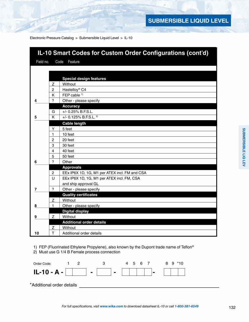
132
SUBMERSIBLE LIQ
LEV
SUBMERSIBLE LIQUID LEVEL
For full specifications, visit www.wika.com to download datasheet IL-10 or call 1-800-381-6549
Electronic Pressure Catalog > Submersible Liquid Level > IL-10
1 2 3 4 5 6 7 8 9 *10
IL-10 - A - - - -
*Additional order details
Order Code:
IL-10 Smart Codes for Custom Order Configurations (cont’d) Field no. Code Feature
1) FEP (Fluorinated Ethylene Propylene), also known by the Dupont trade name of Teflon®
2) Must use G 1/4 B Female process connection
Special design features Z Without 2 Hastelloy® C4 K FEP cable 1) 4 ? Other - please specify Accuracy G +/- 0.25% B.F.S.L. 5 K +/- 0.125% B.F.S.L. 2) Cable length Y 5 feet 1 10 feet 2 20 feet 3 30 feet 4 40 feet 5 50 feet 6 ? Other Approvals 2 EEx IP6X 1D, 1G, M1 per ATEX incl. FM and CSA U EEx IP6X 1D, 1G, M1 per ATEX incl. FM, CSA and ship approval GL 7 ? Other - please specify Quality certificates Z Without 8 1 Other - please specify Digital display 9 Z Without Additional order details Z Without 10 T Additional order details
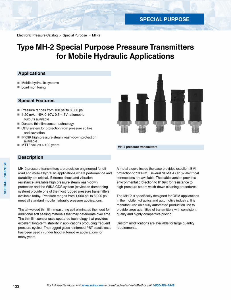
133
SPEC
IAL
PURP
OSE
For full specifications, visit www.wika.com to download datasheet MH-2 or call 1-800-381-6549
Electronic Pressure Catalog > Special Purpose > MH-2
Type MH-2 Special Purpose Pressure Transmitters for Mobile Hydraulic Applications
MH-2 pressure transmitters
Applications
Mobile hydraulic systems Load monitoring
Special Features
Pressure ranges from 100 psi to 8,000 psi 4-20 mA, 1-5V, 0-10V, 0.5-4.5V ratiometric outputs available Durable thin film sensor technology CDS system for protection from pressure spikes and cavitation IP 69K high pressure steam wash-down protection available MTTF values > 100 years
Description
MH-2 pressure transmitters are precision engineered for off road and mobile hydraulic applications where performance and durability are critical. Extreme shock and vibration resistance, available high pressure steam wash-down protection and the WIKA CDS system (cavitation dampening system) provide one of the most rugged pressure transmitters available today. Pressure ranges from 1,000 psi to 8,000 psi meet all standard mobile hydraulic pressure applications.
The all-welded thin film measuring cell eliminates the need for additional soft sealing materials that may deteriorate over time. The thin film sensor uses sputtered technology that provides excellent long-term stability in applications producing frequent pressure cycles. The rugged glass reinforced PBT plastic case has been used in under hood automotive applications for many years.
A metal sleeve inside the case provides excellent EMI protection to 100v/m. Several NEMA 4 / IP 67 electrical connections are available. The cable version provides environmental protection to IP 69K for resistance to high-pressure steam wash-down cleaning procedures.
The MH-2 is specifically designed for OEM applications in the mobile hydraulics and automotive industry. It is manufactured on a fully automated production line to provide large quantities of transmitters with consistent quality and highly competitive pricing.
Custom modifications are available for large quantity requirements.
SPECIAL PURPOSE
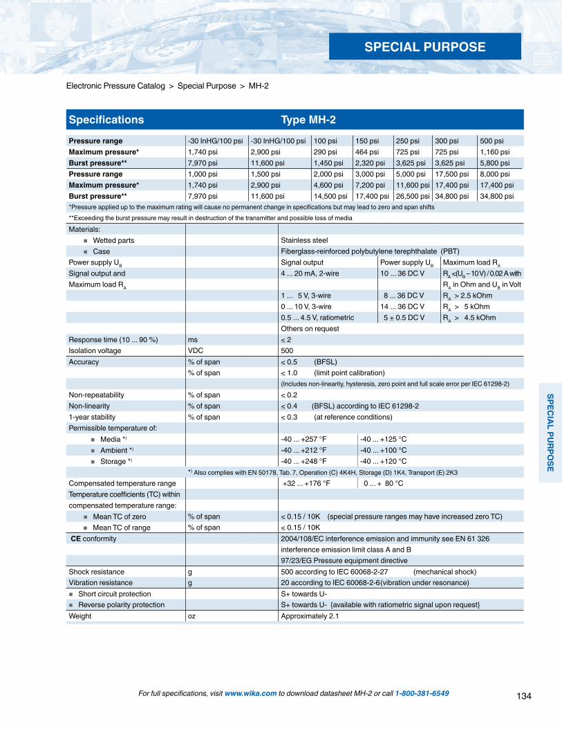
134
SPECIAL PU
RPOSE
SPECIAL PURPOSE
For full specifications, visit www.wika.com to download datasheet MH-2 or call 1-800-381-6549
Electronic Pressure Catalog > Special Purpose > MH-2
Specifications Type MH-2
Pressure range -30 InHG/100 psi -30 InHG/100 psi 100 psi 150 psi 250 psi 300 psi 500 psiMaximum pressure* 1,740 psi 2,900 psi 290 psi 464 psi 725 psi 725 psi 1,160 psiBurst pressure** 7,970 psi 11,600 psi 1,450 psi 2,320 psi 3,625 psi 3,625 psi 5,800 psiPressure range 1,000 psi 1,500 psi 2,000 psi 3,000 psi 5,000 psi 17,500 psi 8,000 psiMaximum pressure* 1,740 psi 2,900 psi 4,600 psi 7,200 psi 11,600 psi 17,400 psi 17,400 psiBurst pressure** 7,970 psi 11,600 psi 14,500 psi 17,400 psi 26,500 psi 34,800 psi 34,800 psi*Pressure applied up to the maximum rating will cause no permanent change in specifications but may lead to zero and span shifts**Exceeding the burst pressure may result in destruction of the transmitter and possible loss of media
Materials: Wetted parts Stainless steel Case Fiberglass-reinforced polybutylene terephthalate (PBT) Power supply UB Signal output Power supply UB Maximum load RA
Signal output and 4 ... 20 mA, 2-wire 10 ... 36 DC V RA <(UB – 10 V) / 0.02 A withMaximum load RA RA in Ohm and UB in Volt
1 ... 5 V, 3-wire 8 ... 36 DC V RA > 2.5 kOhm0 ... 10 V, 3-wire 14 ... 36 DC V RA > 5 kOhm0.5 ... 4.5 V, ratiometric 5 + 0.5 DC V RA > 4.5 kOhmOthers on request
Response time (10 ... 90 %) ms < 2 Isolation voltage VDC 500Accuracy % of span < 0.5 (BFSL)
% of span < 1.0 (limit point calibration) (Includes non-linearity, hysteresis, zero point and full scale error per IEC 61298-2)
Non-repeatability % of span < 0.2Non-linearity % of span < 0.4 (BFSL) according to IEC 61298-21-year stability % of span < 0.3 (at reference conditions)Permissible temperature of: Media *) -40 ... +257 °F -40 ... +125 °C Ambient *) -40 ... +212 °F -40 ... +100 °C Storage *) -40 ... +248 °F -40 ... +120 °C
*) Also complies with EN 50178, Tab. 7, Operation (C) 4K4H, Storage (D) 1K4, Transport (E) 2K3Compensated temperature range +32 ... +176 °F 0 ... + 80 °CTemperature coefficients (TC) withincompensated temperature range: Mean TC of zero % of span < 0.15 / 10K (special pressure ranges may have increased zero TC) Mean TC of range % of span < 0.15 / 10K CE conformity 2004/108/EC interference emission and immunity see EN 61 326
interference emission limit class A and B97/23/EG Pressure equipment directive
Shock resistance g 500 according to IEC 60068-2-27 (mechanical shock)Vibration resistance g 20 according to IEC 60068-2-6 (vibration under resonance) Short circuit protection S+ towards U- Reverse polarity protection S+ towards U- available with ratiometric signal upon requestWeight oz Approximately 2.1
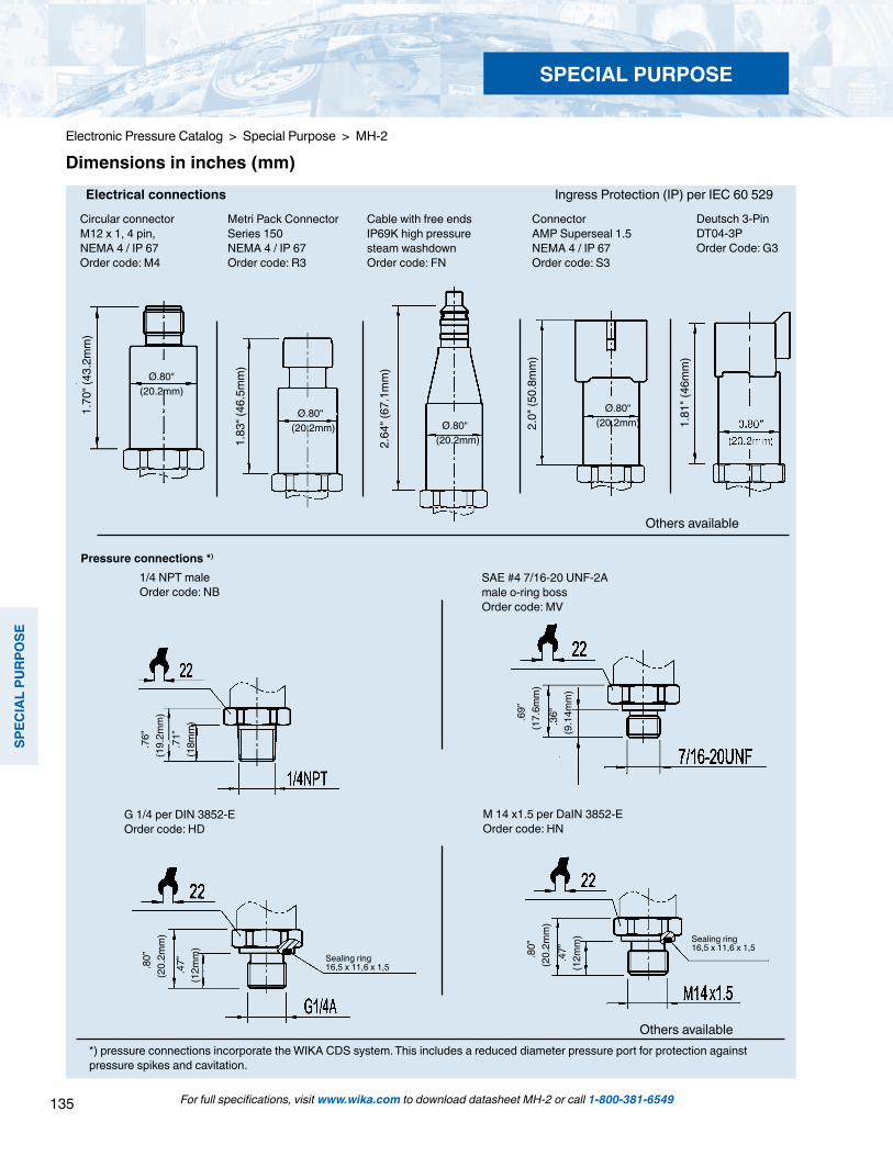
135
SPEC
IAL
PURP
OSE
SPECIAL PURPOSE
For full specifications, visit www.wika.com to download datasheet MH-2 or call 1-800-381-6549
Electronic Pressure Catalog > Special Purpose > MH-2
1.70
“ (43
.2m
m)
Ø.80“ (20.2mm)
Ø.80“ (20.2mm)
1.83
“ (46
.5m
m)
Ø.80“ (20.2mm)
Ø.80“ (20.2mm)
2.64
“ (67
.1m
m)
Electrical connections Ingress Protection (IP) per IEC 60 529
Circular connector M12 x 1, 4 pin,NEMA 4 / IP 67Order code: M4
Metri Pack Connector Series 150NEMA 4 / IP 67Order code: R3
Cable with free endsIP69K high pressure steam washdownOrder code: FN
ConnectorAMP Superseal 1.5NEMA 4 / IP 67Order code: S3
2.0"
(50.
8mm
)
*) pressure connections incorporate the WIKA CDS system. This includes a reduced diameter pressure port for protection against pressure spikes and cavitation.
Dimensions in inches (mm)
Pressure connections *)
.47”
(1
2mm
)
.8
0”
(20.
2mm
)
M 14 x1.5 per DaIN 3852-EOrder code: HN
Sealing ring16,5 x 11,6 x 1,5
G 1/4 per DIN 3852-E Order code: HD
.8
0”
(20.
2mm
)
.4
7”
(12m
m)
Sealing ring16,5 x 11,6 x 1,5
SAE #4 7/16-20 UNF-2A male o-ring bossOrder code: MV
.6
9”
(17.
6mm
)
.36”
(9
.14m
m)
1/4 NPT maleOrder code: NB
.7
6”
(19.
2mm
)
.71”
(1
8mm
)
Deutsch 3-PinDT04-3POrder Code: G3
1.81
" (46
mm
)
Others available
Others available
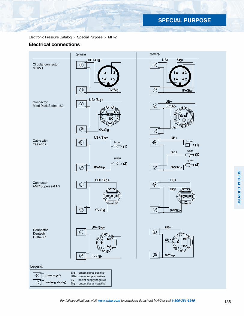
136
SPECIAL PU
RPOSE
SPECIAL PURPOSE
For full specifications, visit www.wika.com to download datasheet MH-2 or call 1-800-381-6549
Electronic Pressure Catalog > Special Purpose > MH-2
Legend:Sig+ output signal positiveUB+ power supply positive0V power supply negativeSig - output signal negative
Circular connectorM 12x1
3-wire2-wire
Cable withfree ends
brown
green
white
brown
green
ConnectorMetri Pack Series 150
ConnectorAMP Superseal 1.5
Electrical connections
ConnectorDeutschDT04-3P
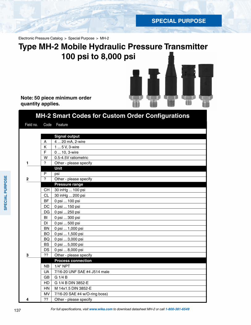
137
SPEC
IAL
PURP
OSE
SPECIAL PURPOSE
For full specifications, visit www.wika.com to download datasheet MH-2 or call 1-800-381-6549
Electronic Pressure Catalog > Special Purpose > MH-2
Type MH-2 Mobile Hydraulic Pressure Transmitter 100 psi to 8,000 psi
Note: 50 piece minimum order quantity applies.
MH-2 Smart Codes for Custom Order Configurations Field no. Code Feature
Signal output A 4 ... 20 mA, 2-wire K 1 ... 5 V, 3-wire F 0 ... 10, 3-wire W 0.5-4.5V ratiometric 1 ? Other - please specify Unit P psi 2 ? Other - please specify Pressure range CH 30 inHg ... 100 psi CL 30 inHg ... 200 psi BF 0 psi ... 100 psi DC 0 psi ... 150 psi DG 0 psi ... 250 psi BI 0 psi ... 300 psi DI 0 psi ... 500 psi BN 0 psi ... 1,000 psi BO 0 psi ... 1,500 psi BQ 0 psi ... 3,000 psi BS 0 psi ... 5,000 psi DS 0 psi ... 8,000 psi 3 ?? Other - please specify Process connection NB 1/4" NPT UA 7/16-20 UNF SAE #4 J514 male GB G 1/4 B HD G 1/4 B DIN 3852-E HN M 14x1.5 DIN 3852-E MV 7/16-20 SAE #4 w/O-ring boss)4 ?? Other - please specify

138
SPECIAL PU
RPOSE
SPECIAL PURPOSE
For full specifications, visit www.wika.com to download datasheet MH-2 or call 1-800-381-6549
Electronic Pressure Catalog > Special Purpose > MH-2
1 2 3 4 5 6 7 8 9 10*
MH-2 - - - - Z -
*Additional order details
Order Code:
MH-2 Smart Codes for Custom Order Configurations (cont’d) Field no. Code Feature
Note: 50 piece minimum order quantity applies.
Case material M Fiberglass reinforced ABS plastic (PBT) 5 V Stainless steel Electrical connection M4 4 Pin locking plug M12 x 1(NEMA 4/IP67) R3 Metri-pack series 150 3-Pin (NEMA 4/IP67) V4 4 Pin bayonet connector (IP69K high pressure seam protection) DIN 72 585 G3 Deutsch 3 Pin DT04-3P S3 AMP superseal 1.5 3 Pin (NEMA 4/IP67) FN Cable with free ends (IP 69K high pressure steam protection) 6 ?? Other - please specify Cable length Z Without (always with plug version) A 0.5 meter (1.6 feet) B 2 meter (6.5 feet) G 5 meter (16.4 feet) 7 ? Other Quality certificates Z Without 8 1 Other - please specify Digital display Z Without 9 1 Other display (order separately) Additional order details Z Without 19 T Additional order details
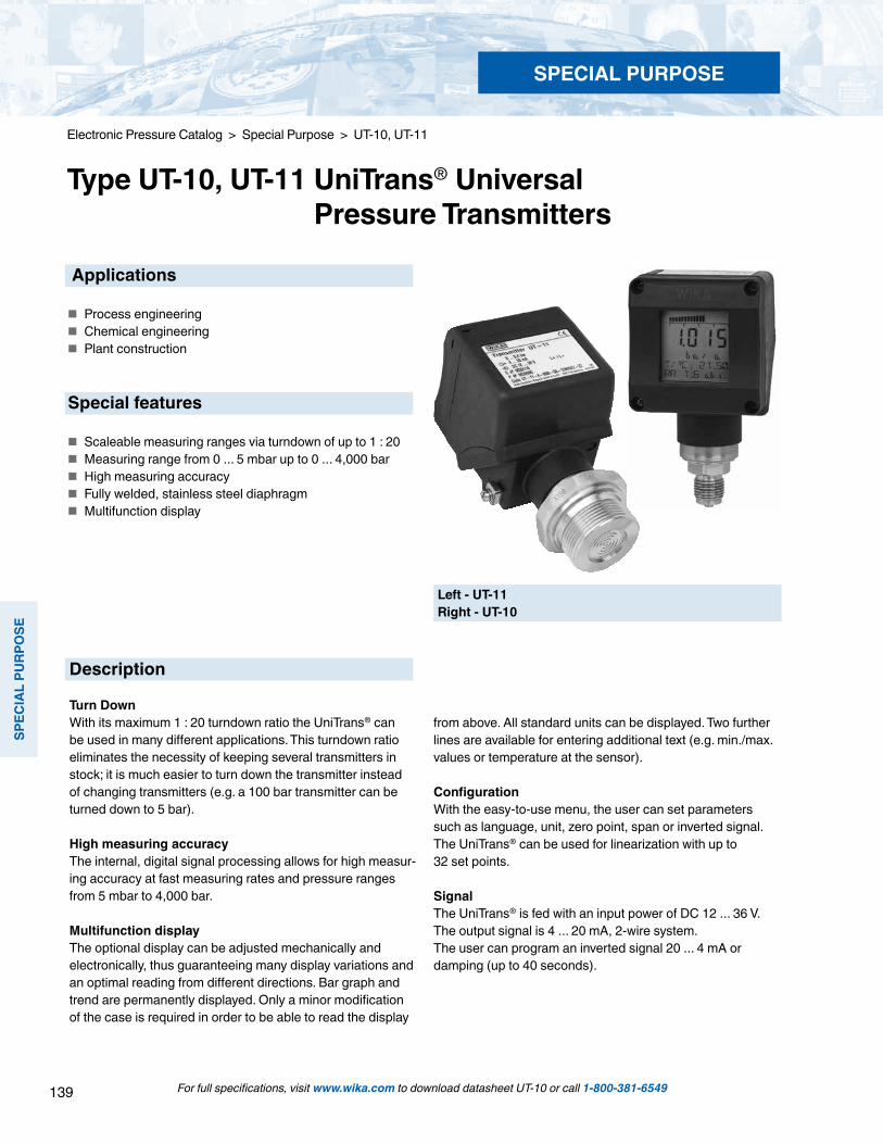
139
SPEC
IAL
PURP
OSE
SPECIAL PURPOSE
For full specifications, visit www.wika.com to download datasheet UT-10 or call 1-800-381-6549
Electronic Pressure Catalog > Special Purpose > UT-10, UT-11
Type UT-10, UT-11 UniTrans® Universal Pressure Transmitters
Description
Turn DownWith its maximum 1 : 20 turndown ratio the UniTrans® can be used in many different applications. This turndown ratio eliminates the necessity of keeping several transmitters in stock; it is much easier to turn down the transmitter instead of changing transmitters (e.g. a 100 bar transmitter can be turned down to 5 bar).
High measuring accuracyThe internal, digital signal processing allows for high measur-ing accuracy at fast measuring rates and pressure ranges from 5 mbar to 4,000 bar.
Multifunction displayThe optional display can be adjusted mechanically and electronically, thus guaranteeing many display variations and an optimal reading from different directions. Bar graph and trend are permanently displayed. Only a minor modification of the case is required in order to be able to read the display
from above. All standard units can be displayed. Two further lines are available for entering additional text (e.g. min./max. values or temperature at the sensor).
ConfigurationWith the easy-to-use menu, the user can set parameters such as language, unit, zero point, span or inverted signal. The UniTrans® can be used for linearization with up to 32 set points.
SignalThe UniTrans® is fed with an input power of DC 12 ... 36 V. The output signal is 4 ... 20 mA, 2-wire system.The user can program an inverted signal 20 ... 4 mA or damping (up to 40 seconds).
Left - UT-11Right - UT-10
Applications
Process engineering Chemical engineering Plant construction
Special features
Scaleable measuring ranges via turndown of up to 1 : 20 Measuring range from 0 ... 5 mbar up to 0 ... 4,000 bar High measuring accuracy Fully welded, stainless steel diaphragm Multifunction display

140
SPECIAL PU
RPOSE
SPECIAL PURPOSE
For full specifications, visit www.wika.com to download datasheet UT-10 or call 1-800-381-6549
Electronic Pressure Catalog > Special Purpose > UT-10, UT-11
Specifications Type UT-10, standard version Type UT-11, flush diaphragm
Pressure ranges 1) * 0.4 bar 1.6 bar 6 bar 16 bar 40 bar 100 bar 250 bar 600 barOver-pressure safety 2 bar 10 bar 35 bar 80 bar 80 bar 200 bar 500 bar 1,200 barBurst pressure 2.4 bar 12 bar 42 bar 96 bar 400 bar 800 bar 1,200 bar 2,4003) barPressure ranges 1) * 1,0002) bar 1,600 2 bar 2,5002) bar 4,0002) barOver-pressure safety 1,500 bar 2,000 bar 3,000 bar 4,400 barBurst pressure 3,000 bar 4,000 bar 5,000 bar 7,000 bar
Vacuum, gauge pressure, compound range, absolute pressure are availableMaterials Wetted parts (other materials see WIKA diaphragm seal program) Type UT-10 Stainless steel (pressure ranges > 16 bar additional Elgiloy®) Type UT-11 Stainless steel Hastelloy® C4; O-ring: NBR 4) FPM/FKM or EPDM Case Highly resistive, fiberglass-enforced plastic (PBT); Aluminum Internal transmission fluid 5) Synthetic oil Halocarbon® oil for oxygen applications
Listed by FDA for Food & BeveragePower supply UB DC V 12 < UB ≤ 36 Signal output 4 ... 20 mA, 2-wire Permissible max. load RA RA ≤ (UB – 12 V) / 0.023 A with RA in Ohm and UB in VoltAdjustability Zero point % -2.5 ... 99 Span Turndown of 1 : 20 (1 : 2 for pressure ranges > 1,000 bar)Internal measuring rate Hz 100Accuracy % of span ≤ 0.1 6) (≤ 0.3 for pressure ranges 1,000 bar)Behavior with turndown (1 : k) turndown of up to 1 : 5 No change of accuracy turndown of 1 : 5 to 1 : 20 The accuracy must be multiplied by the factor (k / 5)
[Calculation example for TD = 1 : 15] Accuracy = 0.1 x (15 : 5) = 0.3Non-linearity % of span ≤ 0.05 (≤ 0.2 for pressure ranges > 1,000 bar); (BFSL) per IEC 61298-21-year stability % of span ≤ 0.1 (at reference conditions)Overall deviation % at +10 ... +40 °C ≤ 0.15 (≤ 0.5 for pressure ranges > 1,000 bar)Permissible temperature of Medium * °C -30 ... +105 (G 1 ½ up to 30 min 140°C at an ambient temperature of < 50 °C)
-30 ... +150 (G 1 according to EHEDG with cooling element) Ambience °C -40 ... +85 7) (-20 ... +70 with display) Storage °C -40 ... +85 (-35 ... +80 with display)Compensated temp. range °C -20 ... +80Temperature coefficients within compensated temp range
(the temperature related deviations in the range +10 ... +40 °C included in the overall deviation)
Mean TC of zero % of span ≤ 0.1/ 10 K Mean TC of range % of span ≤ 0.1 / 10 KDamping s display and signal: 0 ... 40 (adjustable)CE-conformity Pressure equipment directive 97/23/EG (Module H) EMV directive 2004/108/EG, EN 61326 Emission (Group 1, Class B) and immunity (industrial locations)Shock resistance g 100 per IEC 60068-2-27 (mechanical shock)Vibration resistance g 5 per IEC 60068-2-6 (vibration under resonance)Wiring protection Protected against reverse polarity, short circuiting and overvoltage on the instrument sideWeight kg approx. 0.7 Aluminum version approx. 1.0
Items in curved brackets are optional extras for additional price.*) In an oxygen version model UT-11 is not available. In an oxygen version model UT-10 is only available in gauge pressure ranges from 0.4 bar up to max. 1000 bar and with media
temperatures between -20 … +60 °C / -4 … +140 °F.1) Other measuring ranges (e. g. 4 bar) can be set via the respective Turn down. Even when the measuring range is present by us on (e. g. 4 bar) the standard range of (6 bar) can be set
again by a reset.2) Only Type UT-10.3) For Type UT-11: the value specified in the table applies only when sealing is accomplished with the sealing ring underneath the hex. Otherwise max. 1500 bar applies.4) O-ring made of FPM/FKM EPDM for Model UT-11 with integrated cooling element.5) Not for UT-10 with pressure ranges > 25 bar6) Including non-linearity, hysteresis, non-repeatability, zero point and full scale error (corresponds to error of measurement per IEC 61298-2). Adjusted in vertical mounting position with
lower pressure connection.7) -40 °C only with Aluminium case.
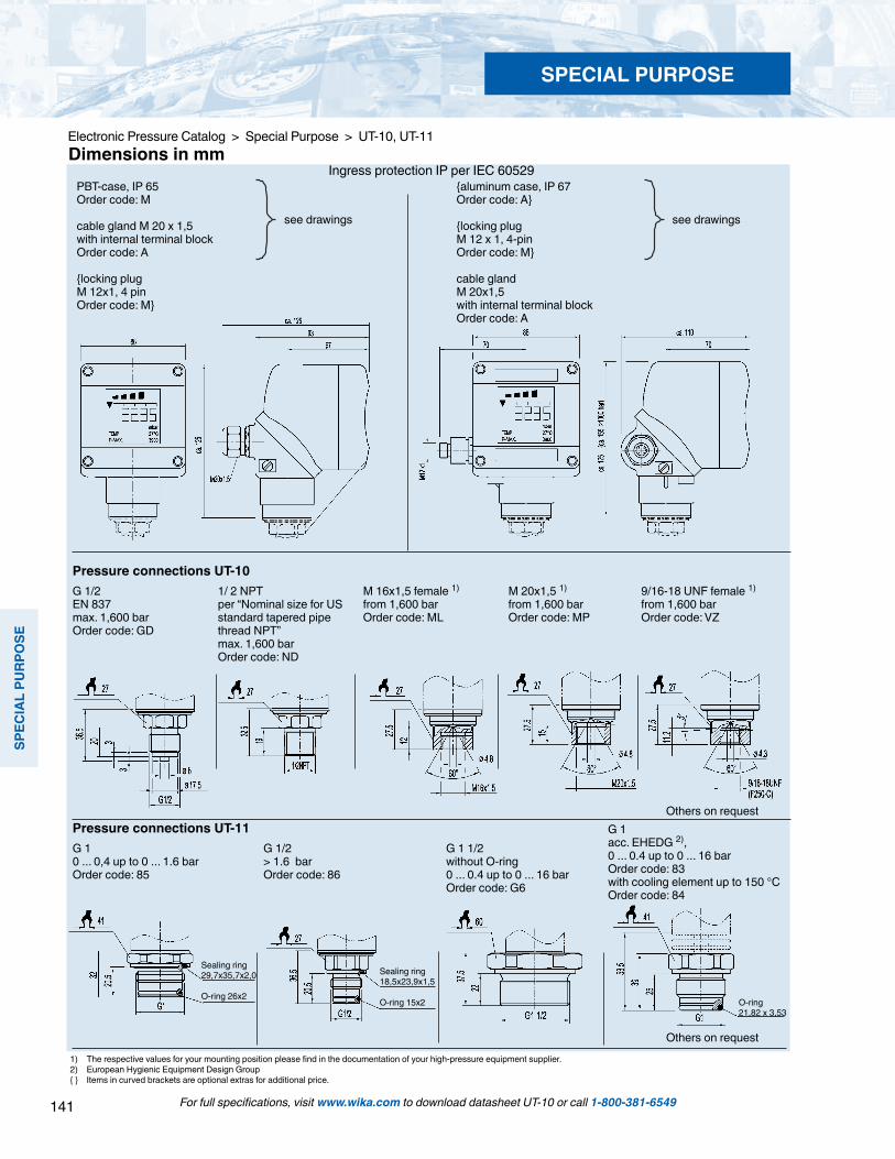
141
SPEC
IAL
PURP
OSE
SPECIAL PURPOSE
For full specifications, visit www.wika.com to download datasheet UT-10 or call 1-800-381-6549
Electronic Pressure Catalog > Special Purpose > UT-10, UT-11
Ingress protection IP per IEC 60529
9/16-18 UNF female 1)
from 1,600 barOrder code: VZ
see drawings
Others on request
O-ring 21,82 x 3,53
Pressure connections UT-11G 1 0 ... 0,4 up to 0 ... 1.6 barOrder code: 85
G 1/2 > 1.6 barOrder code: 86
G 1 1/2 without O-ring0 ... 0.4 up to 0 ... 16 barOrder code: G6
G 1 acc. EHEDG 2), 0 ... 0.4 up to 0 ... 16 barOrder code: 83with cooling element up to 150 °COrder code: 84
PBT-case, IP 65Order code: M
cable gland M 20 x 1,5 with internal terminal blockOrder code: A
locking plugM 12x1, 4 pinOrder code: M
aluminum case, IP 67Order code: A
locking plugM 12 x 1, 4-pinOrder code: M
cable glandM 20x1,5 with internal terminal blockOrder code: A
O-ring 26x2 O-ring 15x2
Dimensions in mm
Pressure connections UT-10 G 1/2EN 837max. 1,600 barOrder code: GD
1/ 2 NPTper “Nominal size for US standard tapered pipe thread NPT”max. 1,600 barOrder code: ND
M 16x1,5 female 1)
from 1,600 barOrder code: ML
M 20x1,5 1)
from 1,600 barOrder code: MP
Others on request
see drawings
Sealing ring29,7x35,7x2,0 Sealing ring
18,5x23,9x1,5
1) The respective values for your mounting position please find in the documentation of your high-pressure equipment supplier.2) European Hygienic Equipment Design Group Items in curved brackets are optional extras for additional price.
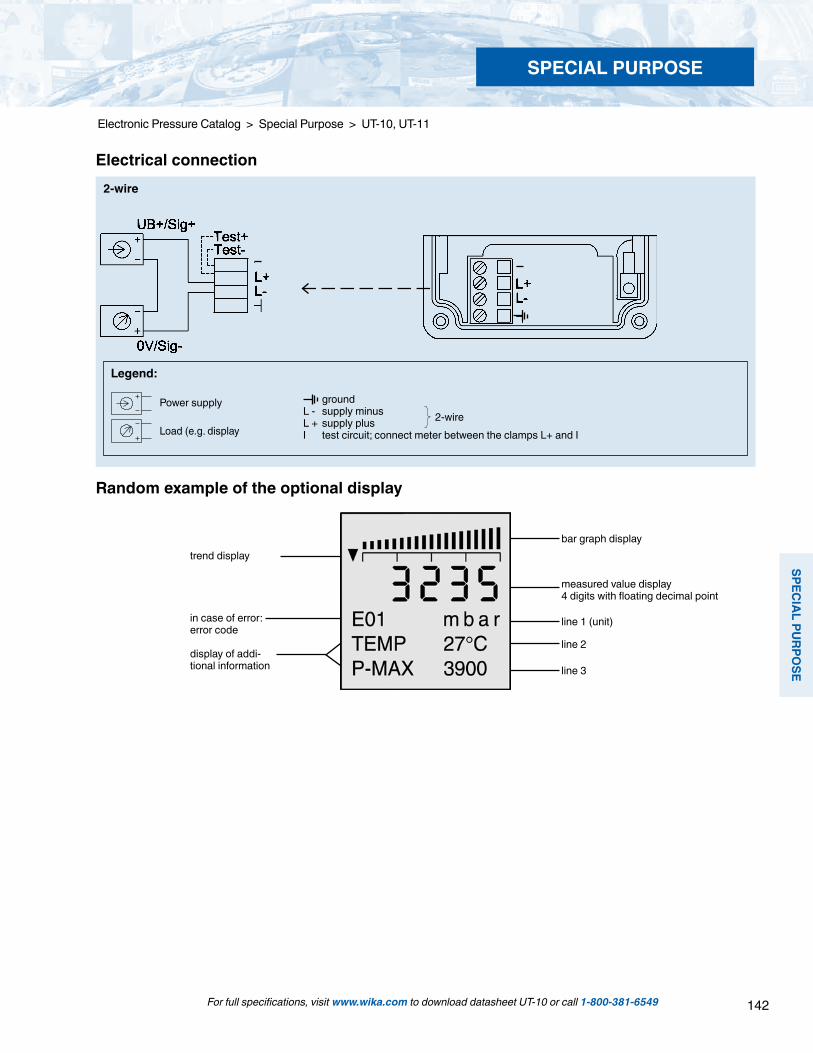
142
SPECIAL PU
RPOSE
SPECIAL PURPOSE
For full specifications, visit www.wika.com to download datasheet UT-10 or call 1-800-381-6549
Electronic Pressure Catalog > Special Purpose > UT-10, UT-11
groundL - supply minusL + supply plusI test circuit; connect meter between the clamps L+ and I
2-wire
Legend:
Electrical connection2-wire
Random example of the optional display
trend display
in case of error:error code
display of addi-tional information
bar graph display
line 1 (unit)
line 2
line 3
measured value display4 digits with floating decimal point
Power supply
Load (e.g. display
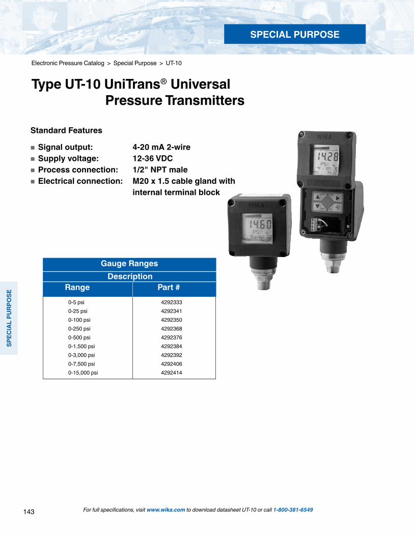
143
SPEC
IAL
PURP
OSE
SPECIAL PURPOSE
Standard Features
Signal output: 4-20 mA 2-wire Supply voltage: 12-36 VDC Process connection: 1/2" NPT male Electrical connection: M20 x 1.5 cable gland with internal terminal block
Gauge Ranges Description Range Part # 0-5 psi 4292333 0-25 psi 4292341 0-100 psi 4292350 0-250 psi 4292368 0-500 psi 4292376 0-1,500 psi 4292384 0-3,000 psi 4292392 0-7,500 psi 4292406 0-15,000 psi 4292414
For full specifications, visit www.wika.com to download datasheet UT-10 or call 1-800-381-6549
Electronic Pressure Catalog > Special Purpose > UT-10
Type UT-10 UniTrans® Universal Pressure Transmitters
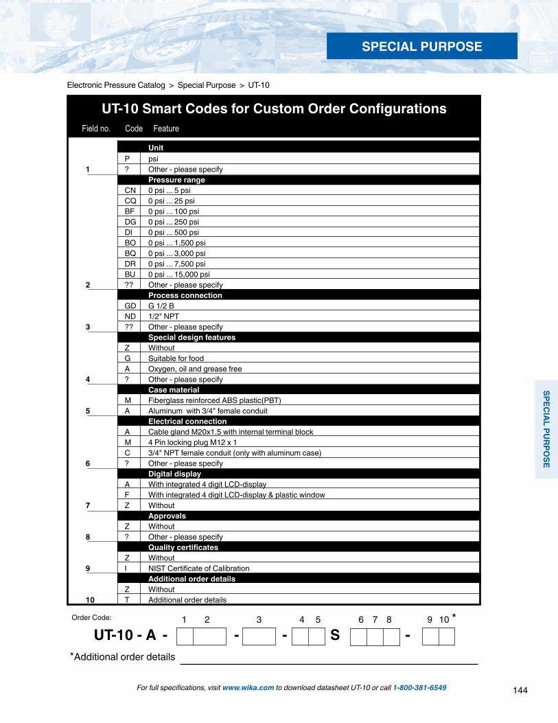
144
SPECIAL PU
RPOSE
SPECIAL PURPOSE
For full specifications, visit www.wika.com to download datasheet UT-10 or call 1-800-381-6549
Electronic Pressure Catalog > Special Purpose > UT-10
1 2 3 4 5 6 7 8 9 10 *UT-10 - A - - - S -
*Additional order details
Order Code:
UT-10 Smart Codes for Custom Order Configurations Field no. Code Feature
Unit P psi 1 ? Other - please specify Pressure range CN 0 psi ... 5 psi CQ 0 psi ... 25 psi BF 0 psi ... 100 psi DG 0 psi ... 250 psi DI 0 psi ... 500 psi BO 0 psi ... 1,500 psi BQ 0 psi ... 3,000 psi DR 0 psi ... 7,500 psi BU 0 psi ... 15,000 psi 2 ?? Other - please specify Process connection GD G 1/2 B ND 1/2" NPT 3 ?? Other - please specify Special design features Z Without G Suitable for food A Oxygen, oil and grease free 4 ? Other - please specify Case material M Fiberglass reinforced ABS plastic(PBT) 5 A Aluminum with 3/4" female conduit Electrical connection A Cable gland M20x1.5 with internal terminal block M 4 Pin locking plug M12 x 1 C 3/4" NPT female conduit (only with aluminum case) 6 ? Other - please specify Digital display A With integrated 4 digit LCD-display F With integrated 4 digit LCD-display & plastic window 7 Z Without Approvals Z Without 8 ? Other - please specify Quality certificates Z Without 9 I NIST Certificate of Calibration Additional order details Z Without 10 T Additional order details
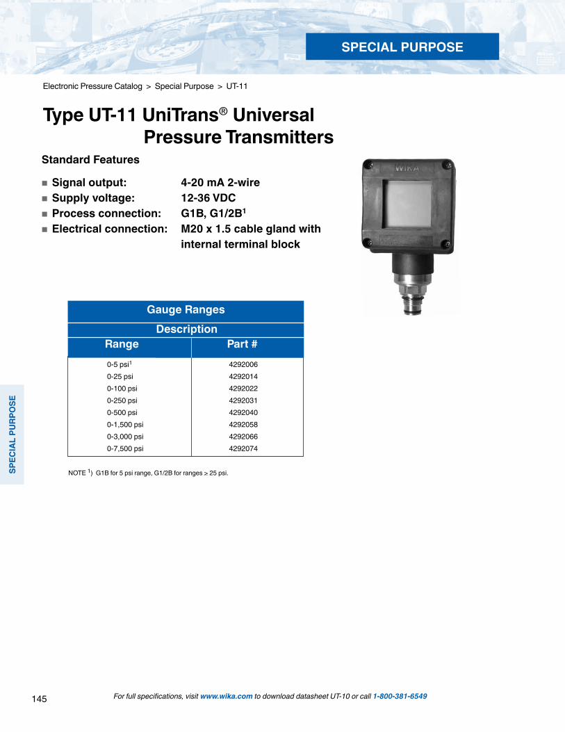
145
SPEC
IAL
PURP
OSE
SPECIAL PURPOSE
For full specifications, visit www.wika.com to download datasheet UT-10 or call 1-800-381-6549
Electronic Pressure Catalog > Special Purpose > UT-11
Type UT-11 UniTrans® Universal Pressure Transmitters
Gauge Ranges Description Range Part # 0-5 psi1 4292006 0-25 psi 4292014 0-100 psi 4292022 0-250 psi 4292031 0-500 psi 4292040 0-1,500 psi 4292058 0-3,000 psi 4292066 0-7,500 psi 4292074
Standard Features
Signal output: 4-20 mA 2-wire Supply voltage: 12-36 VDC Process connection: G1B, G1/2B1
Electrical connection: M20 x 1.5 cable gland with internal terminal block
NOTE 1) G1B for 5 psi range, G1/2B for ranges > 25 psi.

146
SPECIAL PU
RPOSE
SPECIAL PURPOSE
For full specifications, visit www.wika.com to download datasheet UT-10 or call 1-800-381-6549
Electronic Pressure Catalog > Special Purpose > UT-11
*Additional order details
Order Code:
Field no. Code Feature
UT-11 Smart Codes for Custom Order Configurations
1 2 3 4 5 6 7 8 9 10 11*
UT-11 - A - - - S -
Unit P psi 3 psi absolute 1 ? Other - please specify Pressure range CN 0 psi ... 5 psi CQ 0 psi ... 25 psi (0 psi ... 25 psi absolute) BF 0 psi ... 100 psi (0 psi ... 100 psi absolute) DG 0 psi ... 250 psi (0 psi ... 250 psi absolute) DI 0 psi ... 500 psi BO 0 psi ... 1,500 psi BQ 0 psi ... 3,000 psi DR 0 psi ... 7,500 psi 2 ?? Other - please specify Process connection 85 G 1 B, flush diaphragm with O-ring (up to 25 psi) 86 G 1/2 B, flush diaphragm with O-ring (> than 25 psi) 3 ?? Other - please specify Material of wetted parts 1 Stainless steel,NBR O-ring S Hastelloy® C4,Viton® O-ring 4 ? Other- please specify Special design features G Suitable for food 5 Z Without Case material M Fiberglass reinforced ABS plastic(PBT) 6 A Aluminum with 3/4" NPT female conduit Electrical connection A Cable gland M20x1.5 with internal terminal block M 4 pin locking plug M12 x 1 C 3/4" NPT female conduit (only with aluminum case) 7 ? Other - please specify Digital display A With integrated 4 digit LCD-display F With integrated 4 digit LCD-display & plastic window 8 Z Without Approvals Z Without 9 ? Other - please specify Quality certificates Z Without 10 I NIST Certificate of Calibration Additional order details Z Without 11 T Additional order details
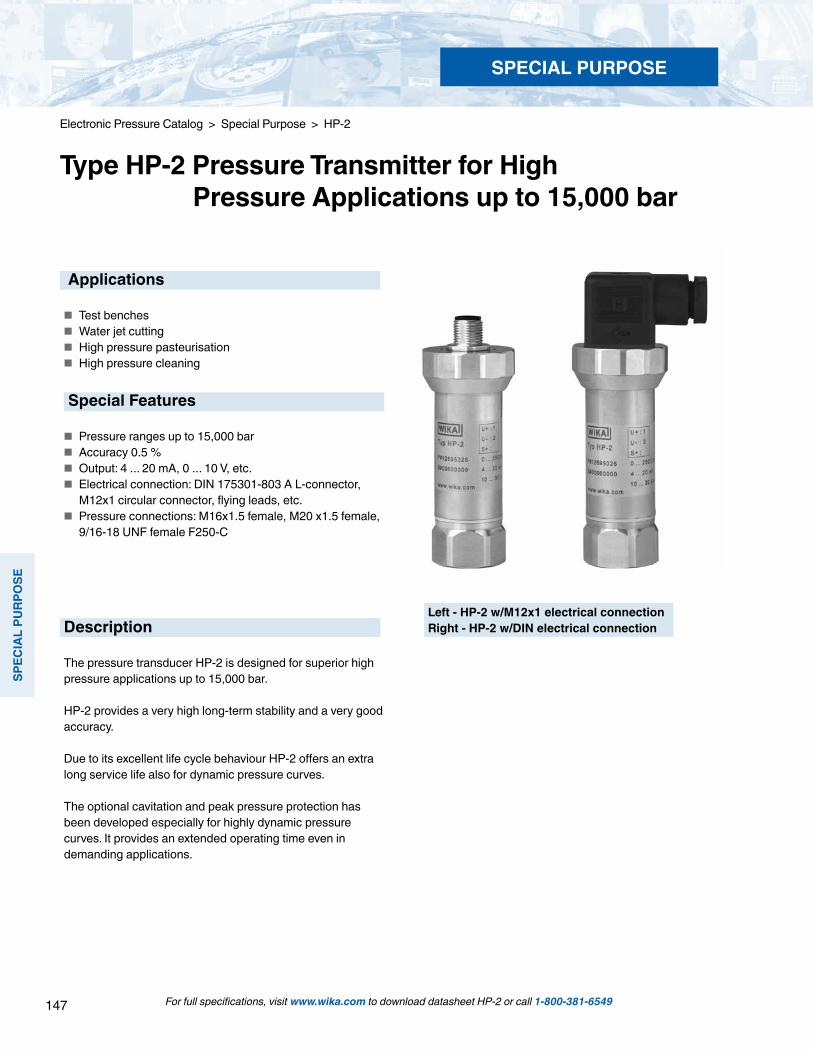
147
SPEC
IAL
PURP
OSE
SPECIAL PURPOSE
For full specifications, visit www.wika.com to download datasheet HP-2 or call 1-800-381-6549
Electronic Pressure Catalog > Special Purpose > HP-2
Type HP-2 Pressure Transmitter for High Pressure Applications up to 15,000 bar
Applications
Test benches Water jet cutting High pressure pasteurisation High pressure cleaning
Special Features
Pressure ranges up to 15,000 bar Accuracy 0.5 % Output: 4 ... 20 mA, 0 ... 10 V, etc. Electrical connection: DIN 175301-803 A L-connector,
M12x1 circular connector, flying leads, etc. Pressure connections: M16x1.5 female, M20 x1.5 female,
9/16-18 UNF female F250-C
Description
The pressure transducer HP-2 is designed for superior high pressure applications up to 15,000 bar.
HP-2 provides a very high long-term stability and a very good accuracy.
Due to its excellent life cycle behaviour HP-2 offers an extra long service life also for dynamic pressure curves.
The optional cavitation and peak pressure protection has been developed especially for highly dynamic pressure curves. It provides an extended operating time even in demanding applications.
Left - HP-2 w/M12x1 electrical connectionRight - HP-2 w/DIN electrical connection

148
SPECIAL PU
RPOSE
SPECIAL PURPOSE
Specifications Type HP-2 Pressure ranges bar 1,600 2,500 4,000 5,000 6,000 7,000 8,000 10,000Over-pressure safety bar 2,300 3,500 5,000 6,000 7,000 8,000 10,000 11,000 Burst pressure bar 4,000 6,000 8,000 10,000 11,000 11,000 12,000 12,000 Pressure ranges psi 23,000 36,000 58,00 72,000 87,000 100,000 115,000 145,000Over-pressure safety psi 33,300 50,500 72,500 87,000 101,500 116,000 145,000 159,500Burst pressure psi 58,000 87,000 116,000 145,000 159,500 159,500 174,000 174,000
Up to 15,000 bar / 217,000 psi on request.Materials Wetted parts 1.4534 Case Stainless steelPower supply UB UB in VDC 10 ... 30 (14 ... 30 with signal output 0 ... 10 V)Signal output and RA in Ohm 4 ... 20 mA, 2-wire RA ≤ (UB – 10 V) / 0.02 Amaximum resistive load RA 0 ... 5 V, 3-wire RA > 5 k
0 ... 10 V, 3-wire RA > 10 kOther signal outputs on request.
Adjustability zero % ± 5 using potentiometers inside the instrumentResponse time (10 ... 90 %) ms ≤ 1Insulation voltage VDC 500Accuracy % of span ≤ ± 0.5 *)
% of span ≤ ± 0.25 *) on request*) Including non-linearity, hysteresis, zero point and full scale error (corresponds to error of measurement per IEC 61298-2).
1-year stability % of span ≤ 0.1 (at reference conditions)Permissible temperature of Medium **) 0 ... +80 °C +32 ... +176 °F Ambience **) -20 ... +80 °C -4 ... +176 °F Storage **) -40 ... +85 °C -40 ... +185 °F
**) Also complies with EN 50178, Tab. 7, Operation (C) 4K4H, Storage (D) 1K4, Transport (E) 2K3Rated temperature range 0 ... +80 °C +32 ... +176 °FTemperature error withinrated temperature range % ≤ 1.0 typ.
≤ 2.5 max.RoHS-conformity on requestCE-conformity Pressure equipment directive 97/23/EC EMC directive 2004/108/EC, EN 61 326 Emission (Group 1, Class B) and
Immunity (industrial locations)Shock resistance g 100 (2.4 ms) according to IEC 60068-2-27Vibration resistance mm 0.35 (10 ... 55 Hz) according to IEC 60068-2-6Wiring protection Short-circuit resistance Sig+ towards UB- Reverse polarity protection UB+ towards UB-Weight kg Approx. 0.3
Electrical connectionsL-connector DIN 175301-803 A Circular connector M12x1 Cable
2-wire UB = 1 0V = 2 UB = 1 0V = 3 UB = brown 0V = green3-wire UB = 1 0V = 2 S+ = 3 UB = 1 0V = 3 S+ = 4 UB = brown 0V = green S+ = whiteWire gauge up to max. 1.5 mm2 - 0.5 mm2 (AWG 20)Diameter of cable 6-8 mm - 6.8 mmIngress protection per IEC 60 529 IP 65 IP 67 IP 67
The ingress protection classes specified only apply while the pressure transmitter is connected with female connectors that provide the corresponding ingress protection.
For full specifications, visit www.wika.com to download datasheet HP-2 or call 1-800-381-6549
Electronic Pressure Catalog > Special Purpose > HP-2

149
SPEC
IAL
PURP
OSE
SPECIAL PURPOSE
Electronic Pressure Catalog > Special Purpose > HP-2
For installation and safety instructions see the operating instructions for this product.The respective values for your mounting torque and maximum pressure please find in the documentation of your high-pressure equipment supplier.*) The respective values for your mounting position please find in the documentation of your high-pressure equipment supplier.
M16x1.5 female,with sealing cone(up to 7000 bar) *)
Order Code: ML
M20x1.5 female,with sealing cone *)
Order Code: MP
9/16-18 UNF female,F250-C(up to 7000 bar) *)
Order Code: VZ
Pressure connections
with optional cavitation and peak pressure protection
Dimensions in mm
L-connectorDIN 175301-803 AOrder Code: A4
Circular connector M 12x1, 4-pinOrder Code: M4
Flying leadswith 1.5 m length (PUR)Order Code: DL
For full specifications, visit www.wika.com to download datasheet HP-2 or call 1-800-381-6549

150
SPECIAL PU
RPOSE
SPECIAL PURPOSE
HP-2 Smart Codes for Custom Order Configurations Field no. Code Feature
Type S Standard D With DIPS (Diaphragm Impact Protection System)1 E With EPS (Exchange Pressure Connection) Non-linearity 2 G 0.25% (B.F.S.L.) Unit B bar P psi3 E MPa Pressure reference 4 G Relative Pressure range 616 0 ... 1,600 bar 625 0 ... 2,500 bar 640 0 ... 4,000 bar 650 0 ... 5,000 bar 660 0 ... 6,000 bar 670 0 ... 7,000 bar 680 0 ... 8,000 bar5 710 0 ... 10,000 bar
Electronic Pressure Catalog > Special Purpose > HP-2
Type HP-2 Pressure Transmitter for High Pressure Applications up to 15,000 bar
For full specifications, visit www.wika.com to download datasheet HP-2 or call 1-800-381-6549
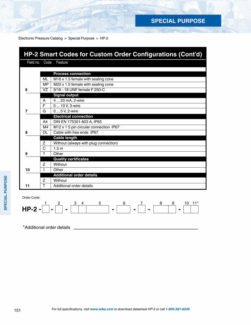
151
SPEC
IAL
PURP
OSE
SPECIAL PURPOSE
HP-2 Smart Codes for Custom Order Configurations (Cont’d) Field no. Code Feature
1 2 3 4 5 6 7 8 9 10 11*
*Additional order details
Order Code:
HP-2 - - - - - - -
Process connection ML M16 x 1.5 female with sealing cone MP M20 x 1.5 female with sealing cone6 VZ 9/16 - 18 UNF female F 250-C Signal output A 4 ... 20 mA, 2-wire F 0 ... 10 V, 3-wire7 G 0 ... 5 V, 2-wire Electrical connection A4 DIN EN 175301-803 A, IP65 M4 M12 x 1 5 pin circular connection IP67 8 DL Cable with free ends IP67 Cable length Z Without (always with plug connection) C 1.5 m 9 ? Other Quality certificates Z Without10 1 Other Additional order details Z Without11 T Additional order details
For full specifications, visit www.wika.com to download datasheet HP-2 or call 1-800-381-6549
Electronic Pressure Catalog > Special Purpose > HP-2

152
SPECIAL PU
RPOSE
SPECIAL PURPOSE
For full specifications, visit www.wika.com to download datasheet P-30, P-31 or call 1-800-381-6549
Electronic Pressure Catalog > Special Purpose > P-30, P-31
Type P-30, Type P-31 Precision Pressure Transmitter
Type P-30 Precision pressure transmitter
Compact design
The robust, compact design allows the P-30 to be installed into standard 19“ test racks or cabinets with limited space.
Many optional features
Pressure ranges are available from 100 INWC to 15,000 PSI. Vacuum, absolute, compound and other engineering units are available to meet specific requirements. A variety of electrical, process connections, and signal outputs are also available.
The P-31 features a flat, non-clogging flush diaphragm for use with slurries or crystallizing media that may clog the orifice of the P-30.
Description
High precision
The P-30 provides non-linearity of up to 0.04% of span (B.F.S.L.) for precise measurement in critical applications. Each instrument is provided with a test report at no addi-tional cost. Other test certificates are available.
Fast digital data processing
Active temperature compensation of the P-30 is provided by microprocessor-controllled digital signal processing and internal temperature measurements. There is no additional temperature error between 50 ... 140 °F (10 … 60 °C). The advanced digital processing circuity provides a measuring rate of up to 1 ms and is comparable to analog output pres-sure transmitters.
The P-30 can be quickly and easily calibrated using the internal USB service interface and optional EasyCom 2009 configuration software. The software also provides for zero and span point adjustments.
Applications
Test benches Calibration technology Laboratories and maintenance shops Machine building
Special Features
0.1% accuracy with no additional temperature error between 50 ... 140 °F (10 ... 60°C) 0.05% accuracy available 1 kHz measuring rate for fast data acquisition Space saving, compact design Internal USB interface connection for calibration and adjustment

153
SPEC
IAL
PURP
OSE
SPECIAL PURPOSE
For full specifications, visit www.wika.com to download datasheet P-30, P-31 or call 1-800-381-6549
Electronic Pressure Catalog > Special Purpose > P-30, P-31
Power Supply U+ U+ in VDC 9 ... 30 (14 ... 30 with signal output 0 ... 10 V)Signal output and RA in Ohm 4 ... 20 mA, 2-wire RA ≤ (U+ – 9 V) / 0.02 Amaximum load RA 0 ... 20 mA, 3-wire RA ≤ (U+ – 9 V) / 0.02 A 4 ... 20 mA, 3-wire RA ≤ (U+ – 9 V) / 0.02 A 0 ... 5 V, 3-wire RA > 5 k 0 ... 10 V, 3-wire RA > 10 kAdjustability zero % of span -5 ... +20 adjustment using optional EasyCom 2009 software span % of span -20 ... +5 adjustment using optional EasyCom 2009 softwareMeasuring rate ms 1 (with 3-wire); 2 (with 2-wire)Warm-up time min < 10Insulation voltage VDC 500Accuracy 5) % of span ≤ 0.10 in the range 50 ... 140 °F(10 ... 60 °C) < 0.05 at 68 °F / 20 °C 6) 5) Includes non-linearity, hysteresis, zero point and full scale error (corresponds to measurement error per IEC 61298-2). Calibrated in vertical mounting position with pressure connection facing down 6) Not available in compound ranges and pressure ranges ≤ 6 PSINon-linearity % of span ≤ 0.04 (BFSL) according to IEC 61298-21-year stability % of span ≤ 0.1 (at reference conditions)Permissible temperatures: Medium -4 ... +221 °F -20 ... +105 °C Ambient -4 ... +176 °F -20 ... +80 °C Storage -40 ... +185 °F -40 ... +85 °CRated temp. range -4 ... +176 °F -20 ... +80 °CTemperature coefficients within (the temperature error between 50 ... 140 °F (10 ... 60 °C)rated temp range is already included in the above accuracy statement)
Pressure rangesOver-pressure safetyBurst pressurePressure rangesOver-pressure safetyBurst pressure
Pressure rangesOver-pressure safetyBurst pressurePressure rangesOver-pressure safetyBurst pressure
Materials Wetted parts» Type P-30» Type P-31 CaseInternal transmission fluid 3)
100 InWC 5 psi 10 psi 15 psi 25 psi 30 psi 60 psi 100 psi 160 psi 250 psi30 psi 30 psi 60 psi 70 psi 150 psi 150 psi 250 psi 500 psi 500 psi 1,160 psi35 psi 35 psi 70 psi 87 psi 175 psi 175 psi 300 psi 600 psi 600 psi 1,400 psi500 psi 600 psi 1,000 psi 1,500 psi 2,000 psi 3,000 psi 5,000 psi 8,000 psi 10,000 psi1) 15,000 psi1)
725 psi 1,150 psi 1,740 psi 2,900 psi 4,640 psi 7,250 psi 11,600 psi 17,400 psi 21,750 psi 21,750 psi1,400 psi 5,000 psi 8,000 psi 11,600 psi 15,000 psi 17,400 psi 24,650 psi 34,800 psi 43,500 psi 43,500 psi
0.25 bar 0.4 bar 0.6 bar 1 bar 1.6 bar 2.5 bar 4 bar 6 bar 10 bar 16 bar2 bar 2 bar 4 bar 5 bar 10 bar 10 bar 17 bar 35 bar 35 bar 80 bar2.4 bar 2.4 bar 4.8 bar 6 bar 12 bar 12 bar 20.5 bar 42 bar 42 bar 96 bar25 bar 40 bar 60 bar 100 bar 160 bar 250 bar 400 bar 600 bar1) 1,000 bar1)
50 bar 80 bar 120 bar 200 bar 320 bar 500 bar 800 bar 1,200 bar 1,500 bar96 bar 400 bar 550 bar 800 bar 1,000 bar 1,200 bar 1,700 bar 2,400 bar 3,000 bar
Vacuum, gauge pressure, compound ranges and absolute pressures are availablecompound ranges: minimum span 6psi (400 mbar) for example. -200 mbar ... +200 mbar1) Only Type P-30.2) For Type P-31: the value specified in the table applies only when sealing is accomplished usingthe sealing ring underneath the hex. Otherwise a maximum of 22,000 PSI (1,500 bar) applies.
Stainless steel (pressure ranges > 300 psi additional 2.4711 / UNSR 30003) Stainless steel; O-ring: NBR FPM/FKM or EPDM
Stainless steelSynthetic oil3) Does not apply for P-30 with pressure ranges > 300 psi
Specifications Type P-30, P-31

154
SPECIAL PU
RPOSE
SPECIAL PURPOSE
compound ranges: minimum span 6psi (400 mbar) for example. -200 mbar ... +200 mbar1) Only Type P-30.2) For Type P-31: the value specified in the table applies only when sealing is accomplished usingthe sealing ring underneath the hex. Otherwise a maximum of 22,000 PSI (1,500 bar) applies.
Stainless steel (pressure ranges > 300 psi additional 2.4711 / UNSR 30003) Stainless steel; O-ring: NBR FPM/FKM or EPDM
Stainless steelSynthetic oil3) Does not apply for P-30 with pressure ranges > 300 psi
Mean TC of zero % of span ≤ 0.1 / 10 KMean TC of span % of span ≤ 0.1 / 10 KRoHS-conformity Yes (not available with bayonet connector)CE-conformity Pressure equipment directive 97/23/EC EMC directive 2004/108/EEC, EN 61 326 Emission (Group 1, Class B) and Immunity (industrial locations)Shock resistance g 200 according to IEC 60068-2-27 (mechanical shock)Vibration resistance g 10 according to IEC 60068-2-6(vibration under resonance)Wiring protection Short-circuit protection S+ to U-Reverse polarity protection U+ to U-Weight oz (g) Approx. 10.6 (300)
Specifications Type P-30, P-31
For full specifications, visit www.wika.com to download datasheet P-30, P-31 or call 1-800-381-6549
Electronic Pressure Catalog > Special Purpose > P-30, P-31
Circular connectorM12x1, 4 pinOrder Code: M4
Flying leadsOrder Code: DL
Bayonet connector, 6 pinOrder Code: C6
L-connectorDIN 175301-803 AOrder Code: A4
Circular connectorM 16x0.75Order Code: B5
Dimensions in inches (mm)

155
SPEC
IAL
PURP
OSE
SPECIAL PURPOSE
For full specifications, visit www.wika.com to download datasheet P-30, P-31 or call 1-800-381-6549
Electronic Pressure Catalog > Special Purpose > P-30, P-31
P-30 pressure connectionsG 1/4Order Code: GB
G 1/2 male /G 1/4 femaleOrder Code: T4
G 1/2Order Code: GD
G 1/4 femaleEN 837with sealing copper stainless steelOrder Code: TB
1/2 NPT MaleOrder Code: ND
P-31 flush diaphragm pressure connectionsP-30 pressure connectionG 1B0 InWC to 25 psi(0 ... 0.25 up to 0 ... 1.6 bar)
G 1/2 B30 psi to 8,000 psi(0 ... 2.5 up to 0 ... 600 bar)
1/4 NPT MaleOrder Code: NB
Accessories Order-No.USB adaptor cable incl. Software EasyCom 2009 for internal service interface 13193075
Electrical connectionsL-connectorDIN 175301-803 A
Circular connector M12x1, 4 pins Cable with free ends Bayonet connector,
6 pinsCircular connector M16x0.75, 5 pins
2-wire U+ = 1 U- = 2 U+ = 1 U- = 3 U+ = brown U- = blue U+ = A U- = B U+ = 3 U- = 13-wire U+ = 1 U- = 2 S+ = 3 U+ = 1 U- = 3 S+ = 4 U+ = brown U- = blue S+ = black U+ = A U- = B S+ = C U+ = 3 U- = 4 S+ = 1Cable screen - - grey - -Wire gauge max AWG16 (1.5mm2) - AWG20 (0.5 mm2) - -Cable diameter .24 - .32" 6-8 mm - .27" 6.8 mm - -
Ingress Pro-tection per IEC 60 529
IP 65 IP 67 IP 67 IP 67 IP 65
The ingress protection classes above only apply while the pressure transmitter is connected using female connectors that provide the corresponding ingress protection.

156
SPECIAL PU
RPOSE
SPECIAL PURPOSE
For full specifications, visit www.wika.com to download datasheet P-30, P-31 or call 1-800-381-6549
Field no. Code Feature
P-30 Pressure Transmitter for Precision Measurement
Accuracy P 0.1% of span 1 R 0.05% of span Unit P psi 2 ? Other Absolute or relative pressure G Gauge A Absolute 3 V Compound Pressure range 310 -30 InHg...0 320 -30 InHg...+15 psi 331 -30 InHg...+30 psi 345 -30 InHg...+50 psi 379 -30 InHg...+100 psi 412 -30 InHg...+160 psi 415 -30 InHg...+200 psi 234 0...5 psig 0...5 psia 269 0...10 psig 0...10 psia 310 0...15 psig 0...15 psia 317 0...25 psig 0...25 psia 321 0...30 psig 0...30 psia 335 0...50 psig 0...50 psia 369 0...100 psig 0...100 psia 411 0...160 psig 0...160 psia 414 0...200 psig 0...200 psia 421 0...300 psig 434 0...500 psig 469 0...1,000 psig 510 0...1,500 psig 514 0...2,000 psig 521 0...3,000 psig 534 0...5,000 psig 569 0...10,000 psig 4 ??? other
TRONIC > Special Purpose > P-30
Type P-30 Precision Pressure Transmitter

157
SPEC
IAL
PURP
OSE
SPECIAL PURPOSE
For full specifications, visit www.wika.com to download datasheet P-30, P-31 or call 1-800-381-6549
Electronic Pressure Catalog > Special Purpose > P-30
Additional order info YES NO 11 1 Z Quality certificates 12 T Z Additional text
Field no. Code Feature
P-30 Pressure Transmitter for Precision Measurement (cont'd)
*Additional order details
Order Code: 1 2 3 4 5 6 7 8 9 10 11 12
P-30- - - - - -
Easy Com software with cable: Part #13193075
Pressure connection NB 1/4” NPT ND 1/2” NPT GD G 1/2 B GB G 1/4 B HD G 1/4 A DIN 3852-E TB G 1/4 female T4 G 1/2 male / G 1/4 female 5 ?? Other Sealing Z Without (not required for NB, ND, TB or T4)) 1 NBR (only for HD) C Copper (only for GD, GB) S Stainless steel (only for GD, GB) 6 ? Other Special design for media Z None 7 ? Other Signal output A 4 ... 20 mA, 2-wire B 0 ... 20 mA, 3-wire F 0 ... 10 V, 3-wire G 0 ... 5 V, 3-wire 8 V 4 ... 20 mA, 3-wire Electrical connection M4 4 circular connector M12x1, 4 pin B5 Plug, M16 x 0.75, 5 pin C6 Bayonet connector, 6 pin A4 4 pin L-plug DIN EN 175301-803, IP65 9 DL Cable with free ends, IP 67 Cable length Z Without 6 6 ft (only with DL) 7 15 ft (only with DL) 10 ? Other

158
SPECIAL PU
RPOSE
SPECIAL PURPOSE
Field no. Code Feature
P-31 Pressure Transmitter for Precision Measurement
Electronic Pressure Catalog > Special Purpose > P-31
Type P-31 Precision Pressure Transmitter w/Non-clogging Flush Diaphragm
Accuracy P 0.1% of span 1 R 0.05% of span Unit P psi 2 ? Other Absolute or relative pressure G Gauge A Absolute 3 V Compound Pressure range 310 -30 InHg...0 320 -30 InHg...+15 psi 331 -30 InHg...+30 psi 345 -30 InHg...+50 psi 379 -30 InHg...+100 psi 412 -30 InHg...+160 psi 415 -30 InHg...+200 psi 234 0...5 psig 0...5 psia 269 0...10 psig 0...10 psia 310 0...15 psig 0...15 psia 317 0...25 psig 0...25 psia 321 0...30 psig 0...30 psia 335 0...50 psig 0...50 psia 369 0...100 psig 0...100 psia 411 0...160 psig 0...160 psia 414 0...200 psig 0...200 psia 421 0...300 psig 434 0...500 psig 469 0...1,000 psig
For full specifications, visit www.wika.com to download datasheet P-30, P-31 or call 1-800-381-6549
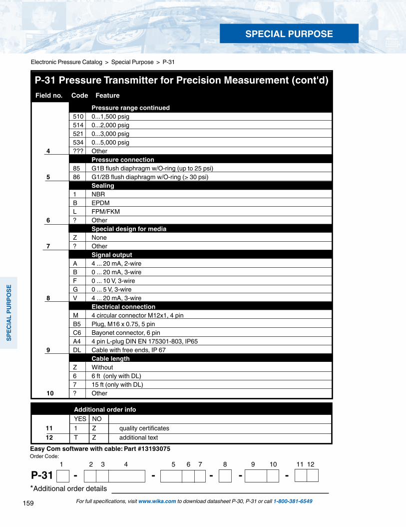
159
SPEC
IAL
PURP
OSE
SPECIAL PURPOSE
For full specifications, visit www.wika.com to download datasheet P-30, P-31 or call 1-800-381-6549
Electronic Pressure Catalog > Special Purpose > P-31
*Additional order details
Additional order info YES NO 11 1 Z quality certificates 12 T Z additional text
Order Code:1 2 3 4 5 6 7 8 9 10 11 12
P-31 - - - - -
Easy Com software with cable: Part #13193075
Field no. Code Feature
P-31 Pressure Transmitter for Precision Measurement (cont'd)
Pressure range continued 510 0...1,500 psig 514 0...2,000 psig 521 0...3,000 psig 534 0...5,000 psig 4 ??? Other Pressure connection 85 G1B flush diaphragm w/O-ring (up to 25 psi) 5 86 G1/2B flush diaphragm w/O-ring (> 30 psi) Sealing 1 NBR B EPDM L FPM/FKM 6 ? Other Special design for media Z None 7 ? Other Signal output A 4 ... 20 mA, 2-wire B 0 ... 20 mA, 3-wire F 0 ... 10 V, 3-wire G 0 ... 5 V, 3-wire 8 V 4 ... 20 mA, 3-wire Electrical connection M 4 circular connector M12x1, 4 pin B5 Plug, M16 x 0.75, 5 pin C6 Bayonet connector, 6 pin A4 4 pin L-plug DIN EN 175301-803, IP65 9 DL Cable with free ends, IP 67 Cable length Z Without 6 6 ft (only with DL) 7 15 ft (only with DL) 10 ? Other

160
SPECIAL PU
RPOSE
SPECIAL PURPOSE
For full specifications, visit www.wika.com to download datasheet R-1 or call 1-800-381-6549
Electronic Pressure Catalog > Special Purpose > R-1
Type R-1 Refrigeration and Air Conditioning Pressure Transmitter
Left: R-1 with M 12x1Center: R-1 with Metri Pack 150Right: R-1 with cable
Description
Refrigeration and Air Conditioning applicationsThe R-1 pressure transmitter is designed for the special requirements of refrigeration and HVAC applications. The all welded stainless steel measuring cell eliminates the need for soft sealing materials between the sensor and process connection. This qualifies the R-1 for use with all typical refrigerants including chlorofluorocarbons R12, R22, R123, R134a and ammonia.
Excellent performance and reliabilityThe R-1 provides a linear amplified output with short circuit, reverse polarity and overvoltage protection. The hermetically welded, dry, thin-film measuring cell provides long-term leak resistance. In addition, the sputtered stainless steel measuring cell features excellent long-term stability and an extremely high burst pressure.
Economical price, high performanceProduction on highly flexible manufacturing lines provides a very attractive price to performance ratio for large production runs.
Applications
Refrigeration and air conditioning applications - Compressor suction and discharge pressure - Compressor staging - Condenser fan controls - Chiller systems
Special Features
Stainless steel wetted parts Compact design is shock and vibration resistant Compatible with all common refrigerants Condensation proof
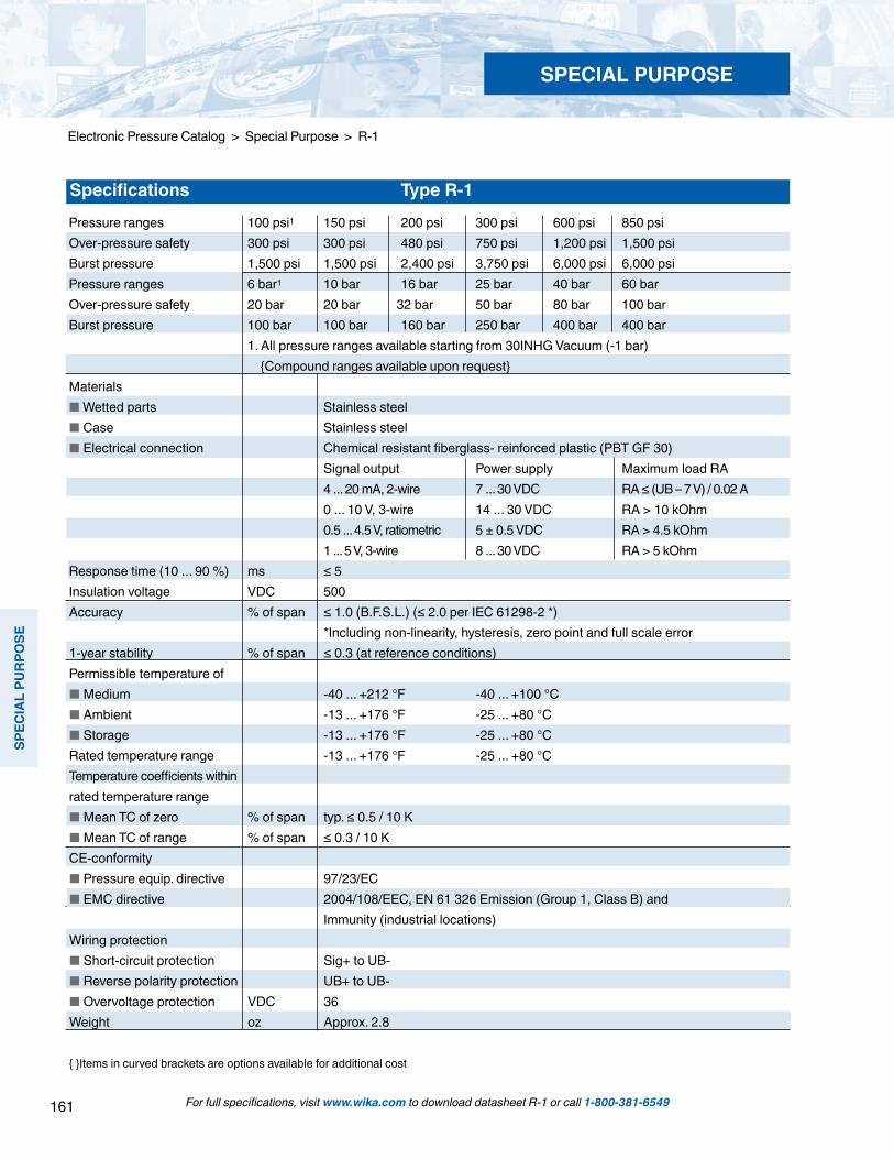
161
SPEC
IAL
PURP
OSE
SPECIAL PURPOSE
For full specifications, visit www.wika.com to download datasheet R-1 or call 1-800-381-6549
Electronic Pressure Catalog > Special Purpose > R-1
Pressure ranges 100 psi1 150 psi 200 psi 300 psi 600 psi 850 psiOver-pressure safety 300 psi 300 psi 480 psi 750 psi 1,200 psi 1,500 psiBurst pressure 1,500 psi 1,500 psi 2,400 psi 3,750 psi 6,000 psi 6,000 psiPressure ranges 6 bar1 10 bar 16 bar 25 bar 40 bar 60 barOver-pressure safety 20 bar 20 bar 32 bar 50 bar 80 bar 100 barBurst pressure 100 bar 100 bar 160 bar 250 bar 400 bar 400 bar 1. All pressure ranges available starting from 30INHG Vacuum (-1 bar) Compound ranges available upon request Materials Wetted parts Stainless steel Case Stainless steel Electrical connection Chemical resistant fiberglass- reinforced plastic (PBT GF 30) Signal output Power supply Maximum load RA 4 ... 20 mA, 2-wire 7 ... 30 VDC RA ≤ (UB – 7 V) / 0.02 A 0 ... 10 V, 3-wire 14 ... 30 VDC RA > 10 kOhm 0.5 ... 4.5 V, ratiometric 5 ± 0.5 VDC RA > 4.5 kOhm 1 ... 5 V, 3-wire 8 ... 30 VDC RA > 5 kOhm Response time (10 ... 90 %) ms ≤ 5Insulation voltage VDC 500Accuracy % of span ≤ 1.0 (B.F.S.L.) (≤ 2.0 per IEC 61298-2 *) *Including non-linearity, hysteresis, zero point and full scale error1-year stability % of span ≤ 0.3 (at reference conditions)Permissible temperature of Medium -40 ... +212 °F -40 ... +100 °C Ambient -13 ... +176 °F -25 ... +80 °C Storage -13 ... +176 °F -25 ... +80 °C Rated temperature range -13 ... +176 °F -25 ... +80 °C Temperature coefficients within rated temperature range Mean TC of zero % of span typ. ≤ 0.5 / 10 K Mean TC of range % of span ≤ 0.3 / 10 KCE-conformity Pressure equip. directive 97/23/EC EMC directive 2004/108/EEC, EN 61 326 Emission (Group 1, Class B) and Immunity (industrial locations) Wiring protection Short-circuit protection Sig+ to UB- Reverse polarity protection UB+ to UB- Overvoltage protection VDC 36Weight oz Approx. 2.8
Items in curved brackets are options available for additional cost
Specifications Type R-1

162
SPECIAL PU
RPOSE
SPECIAL PURPOSE
For full specifications, visit www.wika.com to download datasheet R-1 or call 1-800-381-6549
Electronic Pressure Catalog > Special Purpose > R-1
Dimensions in inches (mm)
Electrical connectionCable with free endsWire gauge: 3 x 0.14 mm² Cable diameter: 3.2 mmIP 69KOrder code: FN
Pressure connection7/16-20 UNF-2A 90° ConeOrder code: U5
Circular connectorM 12x14 pinIP 67Order code: M4
ConnectorMetri Pack Series 1503 pinIP 67Order code: R3
Electrical connections
Example
Cable with free endsWire gauge: 3 x 0.14 mm² Cable diameter: 3.2 mmIP 69K Order code: FN
Pressure connections
Ø 0.87" (22 mm)
0.95" (24 mm)
7/16"-20UNF-2A
appr
ox. 2
.4" 6
1 m
m)
0.59
" (15
mm
)1.
55" 4
0 m
m)
Ø 0.87" (22 mm)
Ø 0.87" (22 mm)
Ø 0.87" (22 mm)
1.52
" (38
.5 m
m)
1.25
" (31
.7 m
m)
1.55
" (40
mm
)
1/8" NPT 1/4" NPT
0.63
" (16
mm
)
0.39
" (1
0 m
m)
0.95" (24 mm)
0.75
" (19
mm
)
0.51
" (1
3 m
m)
0.95" (24 mm)
Ingress Protection IP per IEC 60529. The ingress protection ratings specified only apply while the pressure transmitter is connected with mating connectors that provide the corresponding ingress protection.
1/8 NPT maleOrder Code: NH
1/4 NPT maleOrder Code: NB
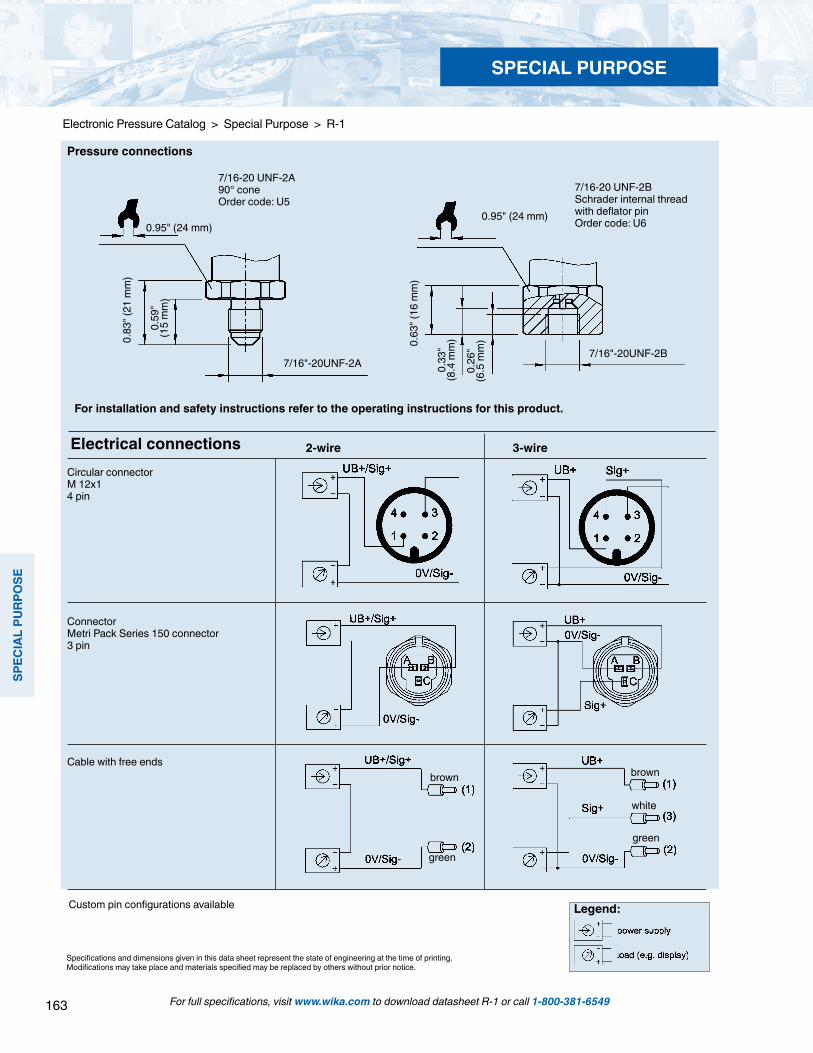
163
SPEC
IAL
PURP
OSE
SPECIAL PURPOSE
For full specifications, visit www.wika.com to download datasheet R-1 or call 1-800-381-6549
Electronic Pressure Catalog > Special Purpose > R-1
7/16"-20UNF-2A7/16"-20UNF-2B
0.83
" (21
mm
)
0.59
" (1
5 m
m)
0.95" (24 mm)
0.63
" (16
mm
)
0.26
" (6
.5 m
m)
0.95" (24 mm)
0.33
" (8
.4 m
m)
Pressure connections
7/16-20 UNF-2BSchrader internal thread with deflator pinOrder code: U6
7/16-20 UNF-2A 90° coneOrder code: U5
Electrical connectionsCircular connectorM 12x14 pin
Connector Metri Pack Series 150 connector3 pin
Cable with free endsbrown
green
brown
green
white
3-wire2-wire
Legend:Custom pin configurations available
Specifications and dimensions given in this data sheet represent the state of engineering at the time of printing.Modifications may take place and materials specified may be replaced by others without prior notice.
For installation and safety instructions refer to the operating instructions for this product.

164
SPECIAL PU
RPOSE
SPECIAL PURPOSE
For full specifications, visit www.wika.com to download datasheet R-1 or call 1-800-381-6549
TRONIC > Special Purpose > R-1
Type R-1 Refrigeration & AC Transmitter
All stainless steel construction Welded case-to-socket connection
R-1 Smart Codes for Custom Order Configurations Field no. Code Feature
Note: 50 piece minimum order quantity applies.
Accuracy 1 A (</=) 1.0% (B.F.S.L) Unit P psi B bar 2 ? Other - please specify Reference G Gauge 3 V Compound Pressure range 379 -30 InHg...+100 psi 415 -30 InHg...+200 psi 422 -30 InHg...+300 psi 442 -30 InHg...+600 psi 369 0...100 psi 410 0...150 psi 414 0...200 psi 421 0...300 psi 441 0...600 psi 459 0...850 psi 411 -1...+10 bar 426 -1...+25 bar 360 0...6 bar 410 0...10 bar 416 0...16 bar 425 0...25 bar 440 0...40 bar 460 0...60 bar 4 ? Other

165
SPEC
IAL
PURP
OSE
SPECIAL PURPOSE
For full specifications, visit www.wika.com to download datasheet R-1 or call 1-800-381-6549
Electronic Pressure Catalog > Special Purpose > R-1
R-1 Smart Codes for Custom Order Configurations (cont’d) Field no. Code Feature
1 2 3 4 5 6 7 8 9 10 11
R-1 - - - - - Additional order details
Order Code:
Note: 50 piece minimum order quantity applies.
Process connection NH 1/8" NPT NB 1/4" NPT U5 7/16-20UNF-2A 90o Cone U6 7/16-20UNF-2B Schrader HA G 1/4 B EN 837 5 ? Other Signal output W 0.5-4.5V 3-wire ratiometric A 4-20mA 2-wire K 1-5V 3-wire 6 F 0-10V 3-wire Supply voltage E 5 V DC +/- 10% (only with signal output W) G 7...30 V DC (only with signal output A or K) 7 C 14...30 V DC (only with signal output F) Electrical connection R3 Metri pack series 150 3 pin connector (NEMA 4 / IP 67) M4 4 Pin locking plug M12 x 1 (NEMA 4 / IP 67) 8 FN Cable with free ends (NEMA 4 / IP 69K high pressure steam protection) Cable length A 0.5 m (1.6 feet) H 1 m (3.28 feet) B 2 m (6.5 feet) G 5 m (16.4 feet) Z Without (always with electrical connection R3 or M4) 9 ? Other Approvals Z Without 10 W c UL us Additional order details Z Without 11 T Additional order details
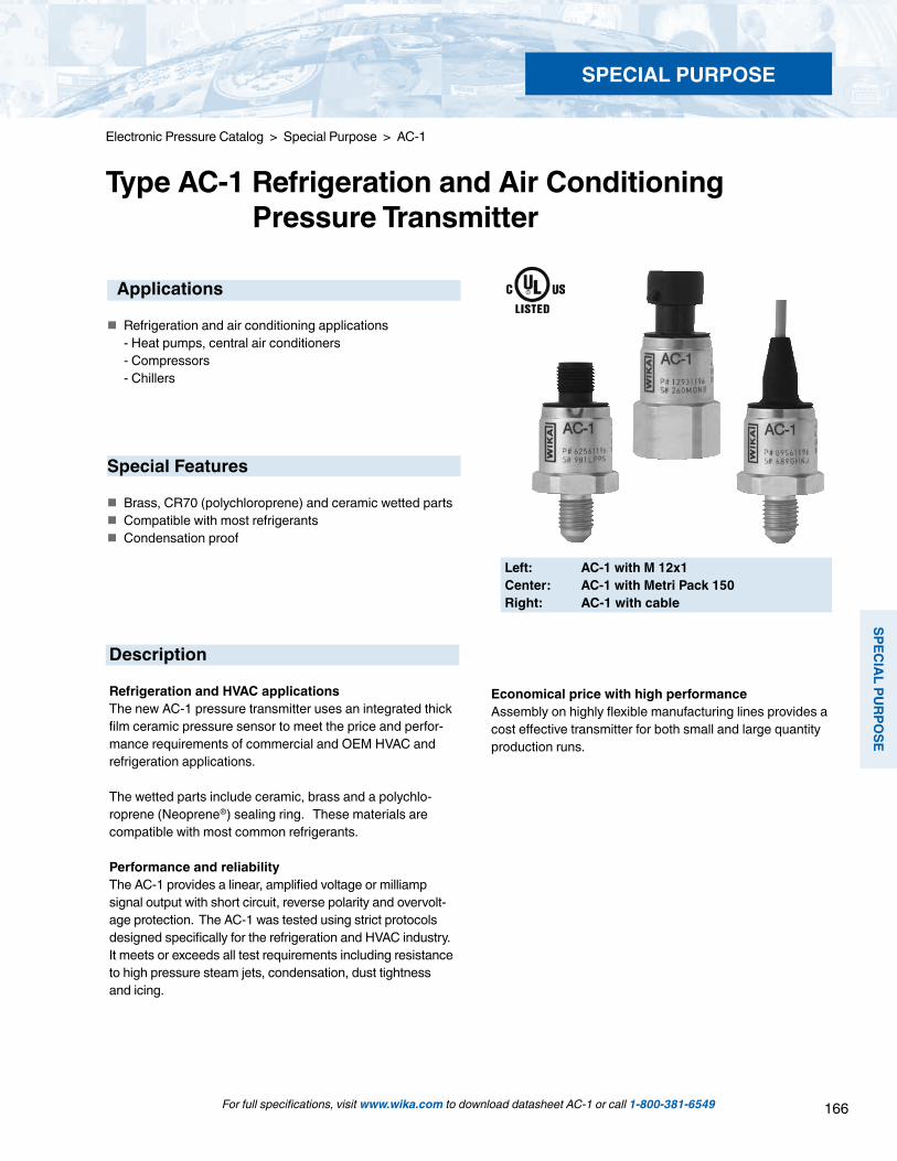
166
SPECIAL PU
RPOSE
SPECIAL PURPOSE
For full specifications, visit www.wika.com to download datasheet AC-1 or call 1-800-381-6549
Electronic Pressure Catalog > Special Purpose > AC-1
Type AC-1 Refrigeration and Air Conditioning Pressure Transmitter
Description
Refrigeration and HVAC applicationsThe new AC-1 pressure transmitter uses an integrated thick film ceramic pressure sensor to meet the price and perfor-mance requirements of commercial and OEM HVAC and refrigeration applications.
The wetted parts include ceramic, brass and a polychlo-roprene (Neoprene®) sealing ring. These materials are compatible with most common refrigerants.
Performance and reliabilityThe AC-1 provides a linear, amplified voltage or milliamp signal output with short circuit, reverse polarity and overvolt-age protection. The AC-1 was tested using strict protocols designed specifically for the refrigeration and HVAC industry. It meets or exceeds all test requirements including resistance to high pressure steam jets, condensation, dust tightness and icing.
Economical price with high performanceAssembly on highly flexible manufacturing lines provides a cost effective transmitter for both small and large quantity production runs.
Applications
Refrigeration and air conditioning applications - Heat pumps, central air conditioners - Compressors - Chillers
Special Features
Brass, CR70 (polychloroprene) and ceramic wetted parts Compatible with most refrigerants Condensation proof
Left: AC-1 with M 12x1Center: AC-1 with Metri Pack 150Right: AC-1 with cable
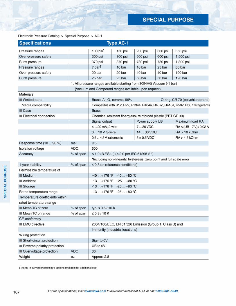
167
SPEC
IAL
PURP
OSE
SPECIAL PURPOSE
For full specifications, visit www.wika.com to download datasheet AC-1 or call 1-800-381-6549
Electronic Pressure Catalog > Special Purpose > AC-1
Pressure ranges 100 psi1 150 psi 200 psi 300 psi 850 psiOver-pressure safety 300 psi 300 psi 600 psi 600 psi 1,500 psiBurst pressure 370 psi 370 psi 730 psi 730 psi 1,800 psiPressure ranges 7 bar1 10 bar 16 bar 25 bar 60 barOver-pressure safety 20 bar 20 bar 40 bar 40 bar 100 barBurst pressure 25 bar 25 bar 50 bar 50 bar 120 bar 1. All pressure ranges available starting from 30INHG Vacuum (-1 bar) Vacuum and Compound ranges available upon request Materials Wetted parts Brass, Al2 O3 ceramic 96% O-ring: CR 70 (polychloroprene) Media compatibility Compatible with R12, R22, R134a, R404a, R407c, R410a, R502, R507 refrigerants Case Brass Electrical connection Chemical resistant fiberglass- reinforced plastic (PBT GF 30) Signal output Power supply UB Maximum load RA 4 ... 20 mA, 2-wire 7 ... 30 VDC RA ≤ (UB – 7 V) / 0.02 A 0 ... 10 V, 3-wire 14 ... 30 VDC RA > 10 kOhm 0.5 ... 4.5 V, ratiometric 5 ± 0.5 VDC RA > 4.5 kOhmResponse time (10 ... 90 %) ms ≤ 5Isolation voltage VDC 500Accuracy % of span ≤ 1.0 (B.F.S.L.) (≤ 2.0 per IEC 61298-2 *) *Including non-linearity, hysteresis, zero point and full scale error1-year stability % of span ≤ 0.3 (at reference conditions)Permissible temperature of Medium -40 ... +176 °F -40 ... +80 °C Ambient -13 ... +176 °F -25 ... +80 °C Storage -13 ... +176 °F -25 ... +80 °C Rated temperature range -13 ... +176 °F -25 ... +80 °C Temperature coefficients within rated temperature range Mean TC of zero % of span typ. ≤ 0.5 / 10 K Mean TC of range % of span ≤ 0.3 / 10 KCE-conformity EMC directive 2004/108/EEC, EN 61 326 Emission (Group 1, Class B) and Immunity (industrial locations) Wiring protection Short-circuit protection Sig+ to 0V Reverse polarity protection UB to 0V Overvoltage protection VDC 36Weight oz Approx. 2.8
Items in curved brackets are options available for additional cost
Specifications Type AC-1

168
SPECIAL PU
RPOSE
SPECIAL PURPOSE
For full specifications, visit www.wika.com to download datasheet AC-1 or call 1-800-381-6549
Electronic Pressure Catalog > Special Purpose > AC-1
Dimensions in inches (mm)
Pressure connection7/16-20 UNF-2A 90° Cone
Example
Ø 0.87" (22 mm)
0.95" (24 mm)
7/16"-20UNF-2A
appr
ox. 2
.4" 6
1 m
m)
0.59
" (15
mm
)1.
55" 4
0 m
m)
ConnectorMetri Pack Series 150IP67Order Code: R3
Ø 0.87" (22 mm)
1.52
" (38
.5 m
m)
Circular connectorM 12x1Order Code: M4
Ø 0.87" (22 mm)
1.25
" (31
.7 m
m)
Cable with free endsIP69KOrder Code: FN
Ø 0.87" (22 mm)1.
55" (
40 m
m)
1/8" NPT 1/4" NPT
0.63
" (16
mm
)
0.39
" (1
0 m
m)
0.95" (24 mm)
0.75
" (19
mm
)
0.51
" (1
3 m
m)
0.95" (24 mm)
Ingress Protection IP per IEC 60529. The ingress protection ratings specified only apply while the pressure transmitter is connected with mating connectors that provide the corresponding ingress protection.
1/8 NPT MaleOrder Code: NH
1/4 NPT MaleOrder Code: NB

169
SPEC
IAL
PURP
OSE
SPECIAL PURPOSE
For full specifications, visit www.wika.com to download datasheet AC-1 or call 1-800-381-6549
Electronic Pressure Catalog > Special Purpose > AC-1
7/16"-20UNF-2A7/16"-20UNF-2B
0.83
" (21
mm
)
0.59
" (1
5 m
m)
0.95" (24 mm)
0.63
" (16
mm
)
0.26
" (6
.5 m
m)
0.95" (24 mm)
0.33
" (8
.4 m
m)
7/16-20 UNF-2BSchrader internal thread with deflator pinOrder code: U6
7/16-20 UNF-2A 90° coneOrder code: U5
Electrical connectionsCircular connectorM 12x14 pin
Connector Metri Pack Series 150 connector3 pin
Cable with free endsbrown
green
brown
green
white
2-wire
Legend:
Specifications and dimensions given in this data sheet represent the state of engineering at the time of printing.Modifications may take place and materials specified may be replaced by others without prior notice.
For installation and safety instructions refer to the operating instructions.

170
SPECIAL PU
RPOSE
SPECIAL PURPOSE
For full specifications, visit www.wika.com to download datasheet AC-1 or call 1-800-381-6549
Electronic Pressure Catalog > Special Purpose > AC-1
Type AC-1 Air Conditioning and Refrigeration Pressure Transmitter
AC-1 Smart Codes for Custom Order Configurations Field no. Code Feature
AC-1 with M12X1Note: 50 piece minimum order quantity applies.
Accuracy 1 A (</=) 1.0% (B.F.S.L) Unit P psi B bar 2 ? Other - please specify Reference G Gauge 3 V Compound Pressure range 379 -30 InHg...+100 psi 415 -30 InHg...+200 psi 422 -30 InHg...+300 psi 442 -30 InHg...+600 psi 369 0...100 psi 410 0...150 psi 414 0...200 psi 421 0...300 psi 441 0...600 psi 459 0...850 psi 411 -1...+10 bar 426 -1...+25 bar 360 0...6 bar 410 0...10 bar 416 0...16 bar 425 0...25 bar 440 0...40 bar 460 0...60 bar 4 ??? Other Process connection NH 1/8" NPT NB 1/4" NPT U5 7/16-20UNF-2A 90o Cone U6 7/16-20UNF-2B Schrader HA G 1/4 B EN 837 5 ?? Other Sensor seal material C CR70 (polychlororene) 6 ? Other

171
SPEC
IAL
PURP
OSE
SPECIAL PURPOSE
For full specifications, visit www.wika.com to download datasheet AC-1 or call 1-800-381-6549
Electronic Pressure Catalog > Special Purpose > AC-1
1 2 3 4 5 6 7 8 9 10 11 12
AC-1 - - - - - Additional order details
Order Code:
Note: 50 piece minimum order quantity applies.
AC-1 Smart Codes for Custom Order Configurations (cont’d) Field no. Code Feature
Signal output W 0.5-4.5V 3-wire ratiometric A 4-20mA 2-wire F 0-10V 3-wire 7 ? Other S Supply voltage E 5 V DC +/- 10% (only with signal output W) G 7...30 V DC (only with signal output A) 8 C 14...30 V DC (only with signal output F) Electrical connection R3 Metri pack series 150 3 pin connector (NEMA 4 / IP 67) M4 4 Pin locking plug M12 x 1 (NEMA 4 / IP 67) 9 FN Cable with free ends (NEMA 4 / IP 69K high pressure steam protection) Cable length A 0.5 m (1.6 feet) H 1 m (3.28 feet) B 2 m (6.5 feet) G 5 m (16.4 feet) Z Without (always with electrical connection R3 or M4) 10 ? Other Approvals Z Without 11 W c UL us Additional order details Z Without 12 T Additional text
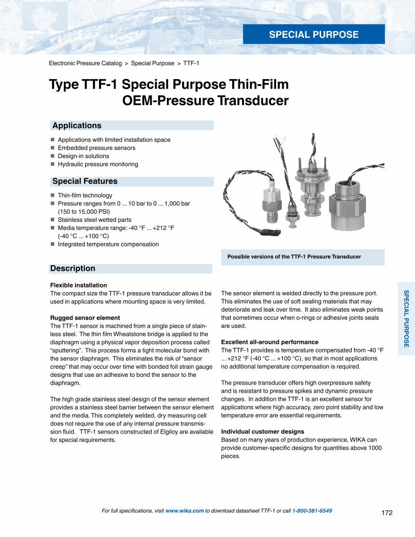
172
SPECIAL PU
RPOSE
SPECIAL PURPOSE
For full specifications, visit www.wika.com to download datasheet TTF-1 or call 1-800-381-6549
Electronic Pressure Catalog > Special Purpose > TTF-1
Type TTF-1 Special Purpose Thin-Film OEM-Pressure Transducer Applications Applications with limited installation space Embedded pressure sensors Design-in solutions Hydraulic pressure monitoring
Special Features Thin-film technology Pressure ranges from 0 ... 10 bar to 0 ... 1,000 bar (150 to 15,000 PSI) Stainless steel wetted parts Media temperature range: -40 °F ... +212 °F (-40 °C ... +100 °C) Integrated temperature compensation
Possible versions of the TTF-1 Pressure Transducer
Description
Flexible installationThe compact size the TTF-1 pressure transducer allows it be used in applications where mounting space is very limited.
Rugged sensor elementThe TTF-1 sensor is machined from a single piece of stain-less steel. The thin film Wheatstone bridge is applied to the diaphragm using a physical vapor deposition process called “sputtering”. This process forms a tight molecular bond with the sensor diaphragm. This eliminates the risk of “sensor creep” that may occur over time with bonded foil strain gauge designs that use an adhesive to bond the sensor to the diaphragm.
The high grade stainless steel design of the sensor element provides a stainless steel barrier between the sensor element and the media. This completely welded, dry measuring cell does not require the use of any internal pressure transmis-sion fluid. TTF-1 sensors constructed of Elgiloy are available for special requirements.
The sensor element is welded directly to the pressure port. This eliminates the use of soft sealing materials that may deteriorate and leak over time. It also eliminates weak points that sometimes occur when o-rings or adhesive joints seals are used.
Excellent all-around performanceThe TTF-1 provides is temperature compensated from -40 °F ... +212 °F (-40 °C ... +100 °C), so that in most applications no additional temperature compensation is required.
The pressure transducer offers high overpressure safety and is resistant to pressure spikes and dynamic pressure changes. In addition the TTF-1 is an excellent sensor for applications where high accuracy, zero point stability and low temperature error are essential requirements.
Individual customer designsBased on many years of production experience, WIKA can provide customer-specific designs for quantities above 1000 pieces.

173
SPEC
IAL
PURP
OSE
SPECIAL PURPOSE
For full specifications, visit www.wika.com to download datasheet TTF-1 or call 1-800-381-6549
Electronic Pressure Catalog > Special Purpose > TTF-1
Specifications and dimensions given in this datasheet represent the state of engineering at the time of printing.Modifications may take place and materials specified may be replaced by others without prior notice.
Dimensions in inches (mm) (1mm = 0.039”)
Typical design example
Circuit diagramblack
blue
red
white
Specification TypeTTF-1 Pressure ranges 10 1)bar 16 1)bar 25 bar 40 .5 bar 60 bar 100 bar 160 bar 250 bar 400 bar 600 bar 1,000 2) bar Over-pressure safety 20 bar 32 bar 50 bar 80 bar 120 bar 200 bar 320 bar 500 bar 800 bar 1,200 bar 1,500 bar Burst pressure 100 bar 160 bar 250 bar 400 bar 550 bar 800 bar 1,000 bar 1,200 bar 1,700 bar 2,400 bar 3,000 bar (1 bar = 14.504 psi) 1) Availability depends on the specific design 2) Higher pressure ranges available on request Pressure connection On request Materials Wetted parts Stainless steel Power supply UB DC V Typical 6 (6 ... 10 recommended) other on request Dielectric strength AC V 500 Insulation resistance MOhm > 300 Bridge resistance RB kOhm 6.5 + 1.3 (between + US and – US) Span at nominal pressure mV/V 2 Zero signal mV/V Typical 0 + 0.2 (maximum 0 + 0.5) Response time (10 ... 90%) ms < 0.1 Linearity (Limit point calibration) With pressure range bar 10 16 25 40 60 100 160 250 400 600 1000 Typical % of span +0.5 +0.4 +0.25 +0.35 +0.30 +0.25 +0.22 +0.20 +0.18 +0.15 +0.12 Span tolerance % of span +30 +25 +15 +20 +15 +15 +15 +15 +15 +15 +15 1-year stability % of span 0.2 (at reference conditions) Permissible temperature of Medium 3) °C -40 ... +212 °F / -40 ... +100 °C Ambient 3) °C -22 ... +176 °F / -40 ... + 80 °C extended temperature range on request Storage 3) °C -22 ... +176 °F / -40 ... + 80 °C extended temperature range on request 3) Also complies with EN 50178, Tab. 7, Operation (C) 4K4H, Storage (D) 1K4, Transport (E) 2K3 Compensated temperature range °C -40 ... +212 °F / -40 ... +100 °C Temperature coefficients within compensated temperature range Mean TC of zero % of span Typical + 0.1/10K Mean TC of range % of span Typical + 0.1/10K Items in curved brackets are optional extras for additional price.

174
METERS & D
ISPLAYS
METERS & DISPLAYS
For full specifications, visit www.wika.com to download datasheet A-AI-1 or call 1-800-381-6549
Electronic Pressure Catalog > Meters & Displays > A-AI-1
Type A-AI-1, A-IAI-1 Attachable Indicator
Display installed on Type S-10 or S-11 transmitter
The IS attachable indicator type A-IAI is designed for use in potentially explosive atmospheres. This IS attachable in-dicator can be combined with an IS-transmitter and with an IS signal isolator or IS transmitter power supply to enable the use in Zone 1 hazardous areas.
The display is provided with an integrated, continuous self-diagnostic circuit that monitors indicator function. The integral self-diagnostic system provides error messages for sensor failure along with upper or lower deviation from the range help provide a high degree of safety.
The sturdy and compact plastic case provides IP65 ingress protection, making the display ideally suited for a great variety of industrial applications.
Applications
Machine tools Test benches Level measurement General industrial applications
Special Features
Display range -1999 ... 9999 Attaches to a 4 ... 20 mA output transmitter using a DIN 43 650 L-plug User- adjustable on site without calibration equipment IP 65 Ingress protection Intrinsically safe explosion protection II 2G EEx ib IIC T4 (type A-IAI-1)
Description
The type A-AI-1 or A-IAI-1 attachable indicator provides an ideal solution for a local read-out with simultaneous 4-20 mA signal transmission.
The universal programmability and simple mounting allows the display to retrofit existing installed transmitters equipped with a full size DIN plug. It is loop powered so no additional power supply is required.
The scaling is adjusted by accessing three buttons under the front cover. The user is prompted through the programming steps by a logically arranged menu and prompts displayed on the LCD.
Two user-selectable filtering levels smooth the display during dynamic pressure changes and brief pressure peaks can be suppressed. All programmed parameters are stored in an EEPROM so in the event of a power failure reprogramming is unnecessary.
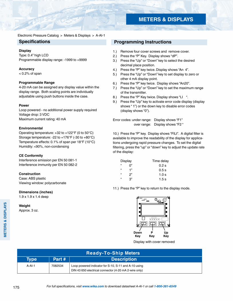
175
MET
ERS
& D
ISPL
AYS
METERS & DISPLAYS
For full specifications, visit www.wika.com to download datasheet A-AI-1 or call 1-800-381-6549
Electronic Pressure Catalog > Meters & Displays > A-AI-1
DownKey
PKey
UpKey
Display with cover removed
Specifications
DisplayType: 0.4” high LCDProgrammable display range: -1999 to +9999
Accuracy< 0.2% of span
Programmable Range4-20 mA can be assigned any display value within the display range. Both scaling points are individually adjustable using push buttons inside the case.
PowerLoop powered - no additional power supply requiredVoltage drop: 3 VDCMaximum current rating: 40 mA
EnvironmentalOperating temperature: +32 to +122°F (0 to 50°C)Storage temperature: -22 to +176°F (-30 to +80°C)Temperature effects: 0.1% of span per 18°F (10°C)Humidity: <90%, non-condensing
CE ConformityInterference emission per EN 50 081-1Interference immunity per EN 50 082-2
ConstructionCase: ABS plasticViewing window: polycarbonate
Dimensions (inches) 1.9 x 1.9 x 1.4 deep
WeightApprox. 3 oz.
Programming Instructions
1.) Remove four cover screws and remove cover.2.) Press the “P” Key. Display shows “dP”. 3.) Press the “Up” or “Down” key to select the desired decimal place position.4.) Press the “P” key twice. Display shows “An 4”.5.) Press the “Up” or “Down” key to set display to zero or other 4 mA display point. 6.) Press the “P” key twice. Display shows “An20”.7.) Press the “Up” or “Down” key to set the maximum range of the transmitter.8.) Press the “P” Key twice. Display shows “LI “.9.) Press the “Up” key to activate error code display (display shows “ 1”) or the down key to disable error codes (display shows “0”).
Error codes: under range: Display shows “F1” over range: Display shows “F2 “
10.) Press the “P” key. Display shows “FILt”. A digital filter is available to improve the readability of the display for applica-tions undergoing rapid pressure changes. To set the digital filtering, press the “up” or “down” key to adjust the update rate of the display:
Display Time delay “ 0” 0.2 s “ 1” 0.5 s “ 2” 1.0 s “ 3” 1.5 s
11.) Press the “P” key to return to the display mode.
Ready-To-Ship Meters Type Part # Description
A-AI-1 7082534 Loop powered indicator for S-10, S-11 and A-10 using DIN 43 650 electrical connector (4-20 mA 2-wire only)

176
METERS & D
ISPLAYS
METERS & DISPLAYS
For full specifications, visit www.wika.com to download datasheet DI-15 or call 1-800-381-6549
Electronic Pressure Catalog > Meters & Displays > DI-15
Type DI-15 Panel Mount Digital Indicator
Applications
Plant construction Machine tools Onboard vehicle displays General industrial applications
Special Features
Multi-function process inputs for standard signals, resistance thermometers and thermocouples Switching point, hysteresis and output type (NPN, PNP, Push-Pull) are all user-selectable EASYBUS Interface included High measuring rate using standard signals
Description
The compact design and multiple signal inputs make the DI15 suitable for many industrial applications.
This universal digital indicator easily adapts to specific measurement tasks and installation requirements without additional tools. Signal input selection is accomplished by using specific terminals on the back of the display and selecting the signal input type in the menu. The display can be programmed in any engineering units and the switch settings are programmable using the push buttons under the front bezel.
A user-friendly, structured menu guides the operator through all the necessary program steps by displaying text in the LED display.
Two user-programmable transistor switching outputs with in-dependently adjustable hysteresis are standard. The digital processing ensures that the alarm set points are switched accurately. The response time can be set from 0 to 99 minutes.
An EASYBUS serial interface for measuring data transfer is a standard feature of the DI-15.
Stainless steel retaining clips are provided for easy instal-lation in panels up to 0.39” (10 mm) thick. The compact design is suitable for installations in locations with limited mounting space such as vehicle dashboards.

177
MET
ERS
& D
ISPL
AYS
METERS & DISPLAYS
For full specifications, visit www.wika.com to download datasheet DI-15 or call 1-800-381-6549
Electronic Pressure Catalog > Meters & Displays > DI-15
Specifications Type DI-15
Display- Design 7-segment-LED, 4-digit, red- Height of digits 0.39” (10 mm)- Indication range -1999 ... 9999Input- Number and type 1 multi-function input for resistance thermometers, thermocouples and standard signals- Input configuration Selectable via terminal connections and menu-driven programming- Resistance thermometers Pt100 3-wire, Pt1000 2-wire max. admissible resistance per wire: 20 Ω- Thermocouples Type K, S, N, J, T- Voltage signals 0 ... 50 mV, 0 ... 1 V, 0 ... 2 V input resistance ≥ 10 kΩ 0 ... 10 V input resistance ≥ 300 kΩ- Current signals 0 ... 20 mA, 4 ... 20 mA input resistance ~125 Ω- Measuring rate Approx. 4/s with temperature sensors, approx. 100/s using standard signalsOutputs 2 switch outputs, not galvanically isolated- Type of output Adjustable: Low-Side (NPN, “GND-switching”) High-Side (PNP, “+Uv-switching”) Push-Pull (change-over between GND and power supply +Uv)- Connection data Low-Side: 28 V, 1 A High-Side: Uv, 200 mA- Output functions 2-step, 3-step, 2-step with alarm, common or separated Min-/Max-alarm- Switching points Freely selectableOperation Via 3 keys (accessible after removing the bezel) or by interfaceInterface EASYBUS, galvanically isolatedPower supply DC 9 ... 28 VCurrent consumption Max. 30 mA (without switch output and interface)Electrical connection Removable screw terminals 2-pin for interface, 9 pin for all remaining connections Wire cross section from 0.14 mm2 to 1.5 mm2
Ambient conditions- Ambient temperature -4 °F ... +122 °F / -20 °C ... +50 °C- Storage temperature -22 °F ... +158 °F / -30 °C ... +70 °C- Humidity 0 ... 80 % relative humidity (non-condensing)Case- Material Fiberglass reinforced Noryl, polycarbonate window- Ingress protection Front: IP 54; IP 65 with use of the provided O-ring seals- Dimensions 1.89” x .95” x 2.56” (48 mm x 24 mm x 65 mm)- Panel cutout 1.77” x .85” (45 mm x 21.7 mm)- Mass Approx. 50 g- Mounting Stainless steel spring clip for a wall thickness from .039” to .39” (1 to 10 mm)
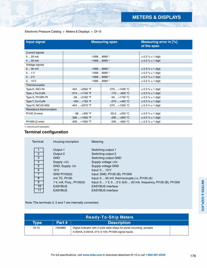
178
METERS & D
ISPLAYS
METERS & DISPLAYS
For full specifications, visit www.wika.com to download datasheet DI-15 or call 1-800-381-6549
Electronic Pressure Catalog > Meters & Displays > DI-15
1234567891011
Input signal Measuring span Measuring error in [%] of the span
Current signals0 ... 20 mA -1999 ... 9999 1) ± 0.2 % ± 1 digit4 ... 20 mA -1999 ... 9999 1) ± 0.2 % ± 1 digitVoltage signals0 ... 50 mV -1999 ... 9999 1) ± 0.3 % ± 1 digit0 ... 1 V -1999 ... 9999 1) ± 0.2 % ± 1 digit0 ... 2 V -1999 ... 9999 1) ± 0.2 % ± 1 digit0 ... 10 V -1999 ... 9999 1) ± 0.2 % ± 1 digitThermocouplesType K, NiCr-Ni -454 ... +2562 °F -270 ... +1406 °C ± 0.3 % ± 1 digitType J, Fe-CuNi -274 ... +1742 °F -170 ... +950 °C ± 0.3 % ± 1 digit Type S, Pt10Rh-Pt -58 ... +3182 °F -50 ... +1750 °C ± 0.5 % ± 1 digitType T, Cu-CuNi -454 ... +752 °F -270 ... +400 °C ± 0.3 % ± 1 digitType N, NiCrSi-NiSi -454 ... +2372 °F -270 ... +1300 °C ± 0.3 % ± 1 digitResistance thermometersPt100 (3-wire) -58 ... +392 °F -50.0 ... +200 °C ± 0.5 % ± 1 digit -328 ... +1562 °F -200 ... +850 °C ± 0.5 % ± 1 digitPt1000 (2-wire) -328 ... +1562 °F -200 ... +850 °C ± 0.5 % ± 1 digit
1) Decimal point adjustable
Terminal Housing inscription Meaning
Output 1 Switching output 1 Output 2 Switching output 2 GND Switching output GND Supply +Uv Supply voltage +Uv GND, Supply -Uv Supply voltage GND 10 V Input: 0 ... 10 V GND Pt100(0) Input: GND, Pt100 (B), Pt1000 mV, TC, Pt100 Input: 0 ... 50 mV, thermocouple (+), Pt100 (A) 1 V, mA, Freq., Pt100(0) Input: 0 ... 1 V, 0 ... 2 V, 0(4) ... 20 mA, frequency, Pt100 (B), Pt1000 EASYBUS EASYBUS interface EASYBUS EASYBUS interface
Note: The terminals 3, 5 and 7 are internally connected.
Terminal configuration
Ready-To-Ship Meters Type Part # Description
DI-15 7464880 Digital indicator with 2 solid state relays for panel mounting, accepts 4-20mA, 0-20mA, 01V, 0-10V, Pt1000 signal inputs.

179
3A S
ANIT
ARY
3A SANITARY
For full specifications, visit www.wika.com to download datasheet S-10-3A or call 1-800-381-6549
Electronic Pressure Catalog > 3A Sanitary > S-10-3A
Type S-10-3A Sanitary Pressure Transmitter
Applications
Food and beverage Pharmaceutical Cosmetic
Special Features
Compliant with 3A Available with 3/4", 1.5" or 2.0" Tri-Clamp® connections 4-20 mA 2-wire output signal, others available Available with an integral cooling extension for high temperature applications Stainless steel case and wetted components
Tri-Clamp® is a registered trademark of Tri-Clover Inc.
Description
WIKA S-10-3A pressure transmitters are in compliance with 3A 3rd party sanitary criteria for pressure and level measure-ment in the food, pharmaceutical, cosmetic and beverage industries. They feature 0.5% accuracy, 0.25 % B.F.S.L, rug-ged stainless steel construction, and a wide operating temperature range.
The 316L SS flush diaphragm minimizes product buildup. The all welded diaphragm seal system includes FDA and USP approved system fill fluid and is designed for "clean in place" (CIP) and "sterilize in place" (SIP) maintenance procedures. The transmitters are available with industry standard 3/4", 1.5" or 2.0" Tri-Clamp® connections. The S-10-3A.C is designed for use with media temperatures up to 350oF (177oC).
Each transmitter undergoes extensive quality control test-ing and calibration. The printed circuit boards use state-of-the-art surface mount technology and are potted in silicone gel for protection against mechanical shock, vibration and moisture. Each transmitter is manufactured to assure accu-racy and long term stability when exposed to severe ambient temperature variations.
>1½" Tri-Clamp® process connection
S-10-3A S-10-3A.C
STANDARD RANGES (1)
RANGE 1.5” Tri-Clamp® 2.0” Tri-Clamp®
Part # Part # 30”-0 HgVac 9766329 9744770 30”-0-30 psi 8997395 4204042 30”-0-60 psi 9799732 4224167 30”-0-100 psi 4204387 4300840 0-15 psi 9748202 9748210 0-30 psi 9748075 4225007 0-50 psi 4215789 4215771 0-60 psi 9744703 9748199 0-100 psi 9748237 9747931 0-160 psi 9748245 9748253 0-200 psi 9749408 4213246 0-250 psi 9776227 4268831 0-300 psi 8990985 4253877 0-500 psi 4205081 9745828 0-1,000 psi 8993470 4281737 (1) Standard part numbers listed above include a S-10-3A, 4-20 mA two wire output signal and a DIN 43650 electrical connector.
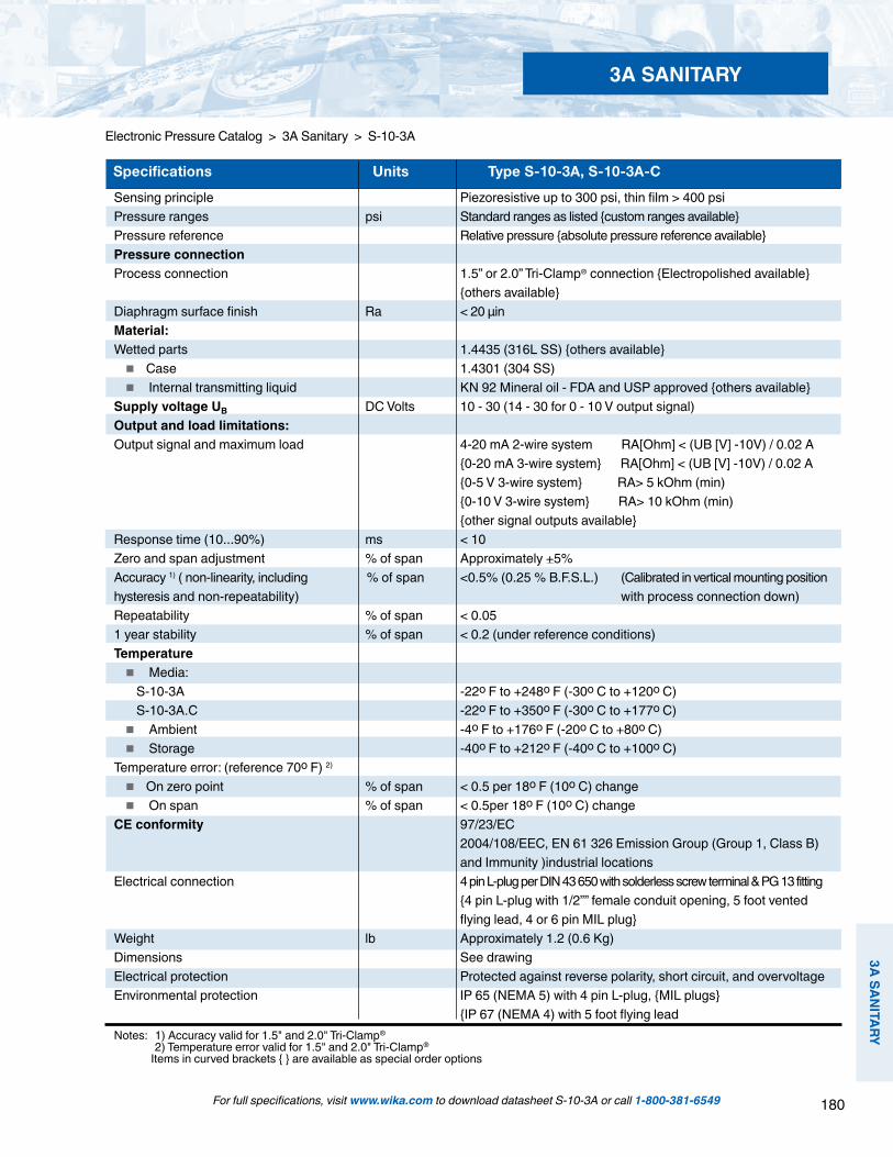
180
3A SANITARY
3A SANITARY
For full specifications, visit www.wika.com to download datasheet S-10-3A or call 1-800-381-6549
Electronic Pressure Catalog > 3A Sanitary > S-10-3A
Sensing principle Piezoresistive up to 300 psi, thin film > 400 psiPressure ranges psi Standard ranges as listed custom ranges availablePressure reference Relative pressure absolute pressure reference availablePressure connectionProcess connection 1.5” or 2.0” Tri-Clamp® connection Electropolished available others availableDiaphragm surface finish Ra < 20 μinMaterial:Wetted parts 1.4435 (316L SS) others available Case 1.4301 (304 SS) Internal transmitting liquid KN 92 Mineral oil - FDA and USP approved others availableSupply voltage UB DC Volts 10 - 30 (14 - 30 for 0 - 10 V output signal)Output and load limitations:Output signal and maximum load 4-20 mA 2-wire system RA[Ohm] < (UB [V] -10V) / 0.02 A 0-20 mA 3-wire system RA[Ohm] < (UB [V] -10V) / 0.02 A 0-5 V 3-wire system RA> 5 kOhm (min) 0-10 V 3-wire system RA> 10 kOhm (min) other signal outputs availableResponse time (10...90%) ms < 10Zero and span adjustment % of span Approximately +5%Accuracy 1) ( non-linearity, including % of span <0.5% (0.25 % B.F.S.L.) (Calibrated in vertical mounting positionhysteresis and non-repeatability) with process connection down)Repeatability % of span < 0.051 year stability % of span < 0.2 (under reference conditions)Temperature Media: S-10-3A -22o F to +248o F (-30o C to +120o C) S-10-3A.C -22o F to +350o F (-30o C to +177o C) Ambient -4o F to +176o F (-20o C to +80o C) Storage -40o F to +212o F (-40o C to +100o C)Temperature error: (reference 70o F) 2)
On zero point % of span < 0.5 per 18o F (10o C) change On span % of span < 0.5per 18o F (10o C) change CE conformity 97/23/EC 2004/108/EEC, EN 61 326 Emission Group (Group 1, Class B) and Immunity )industrial locationsElectrical connection 4 pin L-plug per DIN 43 650 with solderless screw terminal & PG 13 fitting 4 pin L-plug with 1/2”” female conduit opening, 5 foot vented flying lead, 4 or 6 pin MIL plug Weight lb Approximately 1.2 (0.6 Kg)Dimensions See drawingElectrical protection Protected against reverse polarity, short circuit, and overvoltageEnvironmental protection IP 65 (NEMA 5) with 4 pin L-plug, MIL plugs IP 67 (NEMA 4) with 5 foot flying leadNotes: 1) Accuracy valid for 1.5" and 2.0" Tri-Clamp® 2) Temperature error valid for 1.5" and 2.0" Tri-Clamp®
Items in curved brackets are available as special order options
Specifications Units Type S-10-3A, S-10-3A-C

181
3A S
ANIT
ARY
3A SANITARY
For full specifications, visit www.wika.com to download datasheet S-10-3A or call 1-800-381-6549
Electronic Pressure Catalog > 3A Sanitary > S-10-3A
S-10-3A with standard DIN plug
S-10-3A with NEMA 4 cable option
S-10-3A.C with DIN plug and integral cooling extension
1½" and larger Tri-Clamp®
Electrical connections
H1
Ø Mb
Ø DN Ø Mb
Ø DN
Ø Mb
Ø DN
H2
Note: * Accuracy: 1.0% (0.5% B.F.S.L.) Temperature error on zero point: 1.0 per 18o F (10o C) change Temperature error on span: 1.0 per 18o F (10o C) change
Dimensions
Flying leadsconductor cross section up to max. 0.5 mm² / AWG 20 with end splices,conductor outer diameter 6.8 mm, NEMA 4 / IP 67Order code: DL
.71”
(18m
m)1.
69”(
43m
m)
1.14
”(29
mm
)
1.89”(48mm) *)see note
Cable with free ends, adjustablezero and span conductor cross section up to max. 0.5 mm² / AWG 20 with end splices, conductor outer diameter 6.8 mm,NEMA 6 P / IP 68Order code: XM
Circular connector M 12x1, 5-pin,NEMA 4 / IP 67Order code: M5
L-connector, DIN EN 175301-803, Form A(DIN 43 650) for conductor cross section up to max. 1.5 mm² , conductor outer diameter 0.3“ (6-8 mm),NEMA 5 / IP 65Order code: A4
0.91
”(23
mm
)PROCESS CONNECTION DN Mb H1 H2
3/4" Tri-Clamp® * 0.98" 0.6" 5.1" 4.5"
1.5" Tri-Clamp® 1.97" 1.0" 5.0" 4.4"
2.0" Tri-Clamp® 2.52" 1.6" 5.0" 4.4"
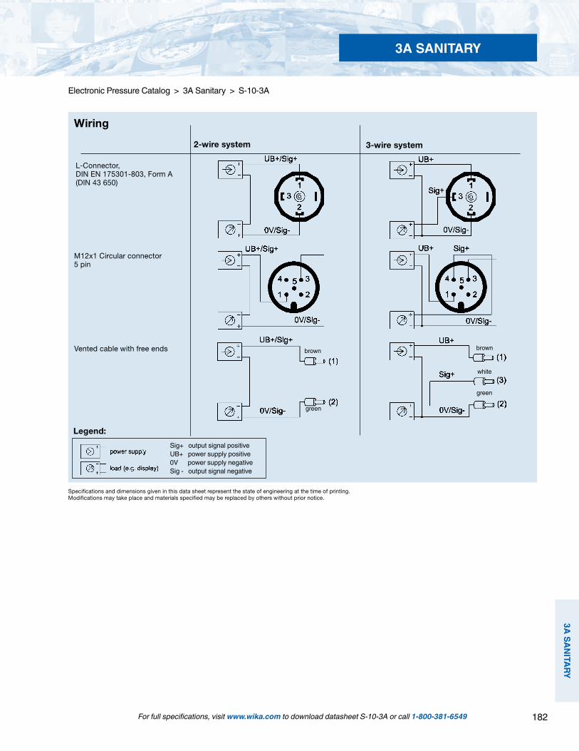
182
3A SANITARY
3A SANITARY
Specifications and dimensions given in this data sheet represent the state of engineering at the time of printing.Modifications may take place and materials specified may be replaced by others without prior notice.
Legend:
L-Connector, DIN EN 175301-803, Form A(DIN 43 650)
Wiring
M12x1 Circular connector5 pin
3-wire system2-wire system
Vented cable with free ends brownbrown
green
white
green
Sig+ output signal positiveUB+ power supply positive0V power supply negativeSig - output signal negative
For full specifications, visit www.wika.com to download datasheet S-10-3A or call 1-800-381-6549
Electronic Pressure Catalog > 3A Sanitary > S-10-3A
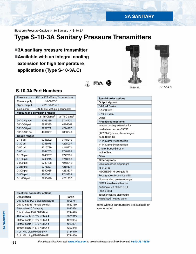
183
3A S
ANIT
ARY
3A SANITARY
Electronic Pressure Catalog > 3A Sanitary > S-10-3A
Type S-10-3A Sanitary Pressure Transmitters
S-10-3A S-10-3A.C
3A sanitary pressure transmitter Available with an integral cooling extension for high temperature applications (Type S-10-3A.C)
Items without part numbers are available on special order.
S-10-3A Part Numbers
Electrical connector optionsDescription Part # DIN 43 650 PG-9 plug (standard) 1006711 DIN 43 650 ½" female conduit 1632159 Attachable LCD display 7082534 5 foot cable IP 67 / NEMA 4 9744479 10 foot cable IP 67 / NEMA 4 9838915 20 foot cable IP 67 / NEMA 4 4239904 30 foot cable IP 67 / NEMA 4 4239921 50 foot cable IP 67 / NEMA 4 4293348 4 pin MIL plug PT02E-8-4P 2184479 6 pin MIL plug PT02E-10-6P 9744460
Special order optionsOutput signals 0-20 mA 3-wire 0-5 V 3-wire 0-10 V 3-wire Other Process connections Integral cooling extension for media temp. up to +350°F (177°C) (Type number changes to S-10.3A.C)3" Tri-Clamp® connection 4" Tri-Clamp® connectionCherry Burrell® I-Line InLine Seal OtherOther options Electropolished diaphragm to <15 Ra NEOBEE® M-20 liquid fill Food grade silicone liquid fill Non-standard pressure range NIST traceable calibration certificate <0.50% B.F.S.L. (part # 502) Teflon® coated diaphragm Hastelloy® wetted parts
For full specifications, visit www.wika.com to download datasheet S-10-3A or call 1-800-381-6549
Pressure conn. 1½" or 2" Tri-Clamp® connectionsPower supply 10-30 VDCSignal output 4-20 mA 2-wireElec. conn. DIN 43 650 with plug connectorVacuum and compound ranges 1.5" Tri-Clamp® 2" Tri-Clamp®
30"-0 Hg vac 9766329 9744770 30"-0-30 psi 8997395 4204042 30"-0-60 psi 9799732 4224167 30"-0-100 psi 4204387 4300840Gauge ranges 0-15 psi 9748202 9748210 0-30 psi 9748075 42250070-50 psi 4215789 42157710-60 psi 9744703 97481990-100 psi 9748237 97479310-160 psi 9748245 97482530-200 psi 9749408 4213246 0-250 psi 9776227 4268831 0-300 psi 8990985 4253877 0-500 psi 4205081 9745828 0-1,000 psi 8993470 4281737

184
3A SANITARY
3A SANITARY
For full specifications, visit www.wika.com to download datasheet SA-11 or call 1-800-381-6549
Description
WIKA SA-11 pressure transmitters meet 3A and EHEDG sanitary criteria for pressure and level measurement in the food, pharmaceutical, cosmetic and beverage industries. They feature 0.25% accuracy, rugged 316L SS wetted construction and a wide operating temperature range.
The SA-11 features an integral cooling extension between the Tri-Clamp® connection and transmitter body. This design increases the maximum permissible media temperature to 150oC (300oF).
The 316L SS flush diaphragm ensures a crevice free seal between the process connection and the pressure measuring diaphragm. The permanently sealed sensing system includes food grade (FDA approved) liquid fill and is designed for "clean in place" (CIP) and "sterilize in place" (SIP) maintenance proce-dures. The transmitters are available with industry standard 1.5" or 2" Tri-Clamp® connections. They can be ordered with an optional NEMA 6P (IP 68) cable assembly for additional protection in wash down areas.
Special features Compliant with 3A sanitary criteria 1.5" and 2" Tri-Clamp® connections Pressure ranges include vacuum, compound and gauge ranges as low as 100 inches water column 4-20 mA 2-wire output signal, others available Designed for media temperature up to 150oC (300oF) Wetted surface finish Ra < 16µ inch
Type SA-11
Tri-Clamp® is a registered trademark of Tri-Clover Inc.
Notes:* Pressure applied up to the maximum rating will cause no permanent change in specifications** Exceeding the burst pressure may result in destruction of the transmitter and loss of media.
Type SA-11 with optional IP 68 cable
Additional ranges are available
STANDARD RANGES
RANGE MAXIMUM* BURST** 0-100 InWC 30 psi 30 psi 0-150 InWC 30 psi 30 psi 0-250 InWC 60 psi 60 psi 0-400 InWC 70 psi 70 psi 0-25 psi 145 psi 145 psi 0-50 psi 250 psi 250 psi 0-100 psi 500 psi 500 psi
Electronic Pressure Catalog > 3A Sanitary > SA-11
Type SA-11 Sanitary Pressure Transmitter
PART NUMBERS
Pressure conn. 1½" or 2" Tri-Clamp® connectionsPower supply 10-30 VDCSignal output 4-20 mA 2-wireElec. conn. DIN 43 650 with plug connectorGauge ranges 1.5" Tri-Clamp® 2" Tri-Clamp®
0-100 InWC 4361853 43618610-150 InWC 43735760-250 InWC 4361887 43618790-400 InWC 503623050-25 psi 42099860-50 psi 4200104 42001130-100 psi 4394866 50006495
Other ranges to 400 psi are available

185
3A S
ANIT
ARY
3A SANITARY
For full specifications, visit www.wika.com to download datasheet SA-11 or call 1-800-381-6549
Electronic Pressure Catalog > 3A Sanitary > SA-11
Specifications Units Type SA-11 Sanitary
Sensing principle PiezoresistivePressure ranges Standard ranges as listed custom ranges available 100 InWC up to 300 psiPressure reference relative pressure absolute and compound are available Pressure connection 1.5” or 2” Tri-Clamp® connection other connections available
Material:-wetted parts 1.4435 (316L SS) -case 1.4571 (316 Ti SS) -internal transmitting liquid Synthetic oil KN 77, FDA approved
Supply voltage UB + DC Volts 10 - 30 (14 - 30 for 0 - 10 V output signal) Output and load limitations:Output signal and maximum load 4-20 mA 2-wire system RA[Ohm] < (UB [V] -10V) / 0.02 A 0-20 mA 3-wire system RA[Ohm] < (U-1 pt [V] -10V) / 0.02 A 0-5 V 3-wire system RA> 5 kOhm (min) 0-10 V 3-wire system RA> 10 kOhm (min) other signal outputs available
Response time (10...90%) ms < 10zero and span adjustment % of span Approximately +5
Accuracy ( non-linearity, including % of span <0.25% (B.F.S.L.) (Calibrated in vertical mounting positionhysteresis and non-repeatability ) with process connection down) 1 year stability % of span < 0.2 (under reference conditions)
TemperatureMedia -4oF to +302oF (-20oC to +150oC)Ambient -4oF to +176oF (-20oC to +80oC)Storage -40oF to +212oF (-40oC to +100oC)Compensated range +32oF to +176oF (0oC to +80oC) Temperature error (reference 70oF)on zero per 18oF (10oC) % of span /10oC <0.25 for 0-150 InWC; <0.40% for 0-100 InWC:<0.20% for >150 InWCon span per 18oF (10oC) % of span /10oC <0.2
CE conformity Interference emission and immunity per EN 61 326
Electrical connection 4 pin L-plug per DIN 43 650 with solderless screw terminal and PG 13 fitting 4 pin L-plug with 1/2” female conduit opening 5 foot vented flying lead 4 or 6 pin MIL plug
Weight lbs. approximately 1.1 (0.5 Kg)Dimensions see drawing
Electrical protection protected against reverse polarity, short circuit and overvoltage
Environmental protection IP 65 (NEMA 5) with 4 pin L-plug, MIL plugs IP 67 (NEMA 4) with 5 foot flying lead IP 68 (NEMA 6P) with vented cable and non-accessible zero and span
Note: Items in curved brackets are available as special order options

186
3A SANITARY
3A SANITARY
Electrical connections
Dimensions
Standard
4 pin L-plugDIN43 650
4 or 6 pin MIL plug(mating connector not included)
Type
Protection
Descriptionand partnumbers
DIN 43 650 plug
IP 65 / NEMA 5
PG9 cable gland(standard)
Part #1006711
1/2" NPT femaleconduit openingPart #1632159
Adjustable LCDDisplay
IP 65 / NEMA 5
Loop poweredprogrammable
4-20 mA3.5 digit
Part #7082534
Vented cable withfree ends
IP 67 / NEMA 4
5 foot - #974447910 foot - #983891520 foot - #423990430 foot - #423992150 foot - #4293348
MIL plug
IP 65 / NEMA 5
4 pinPT02E-8-4P
Part #8990935
6 pinPT02E-10-6PPart #9744460
Description Dimension, ∅D
1.5" Tri-Clamp® 1.97"
2.0" Tri-Clamp® 2.52"
SA-11A withNEMA 4 cable option
ØD
For full specifications, visit www.wika.com to download datasheet SA-11 or call 1-800-381-6549
Electronic Pressure Catalog > 3A Sanitary > SA-11
3.66
”(9
3 m
m)
3.23”(82 mm) 4.
21”
(107
mm
)
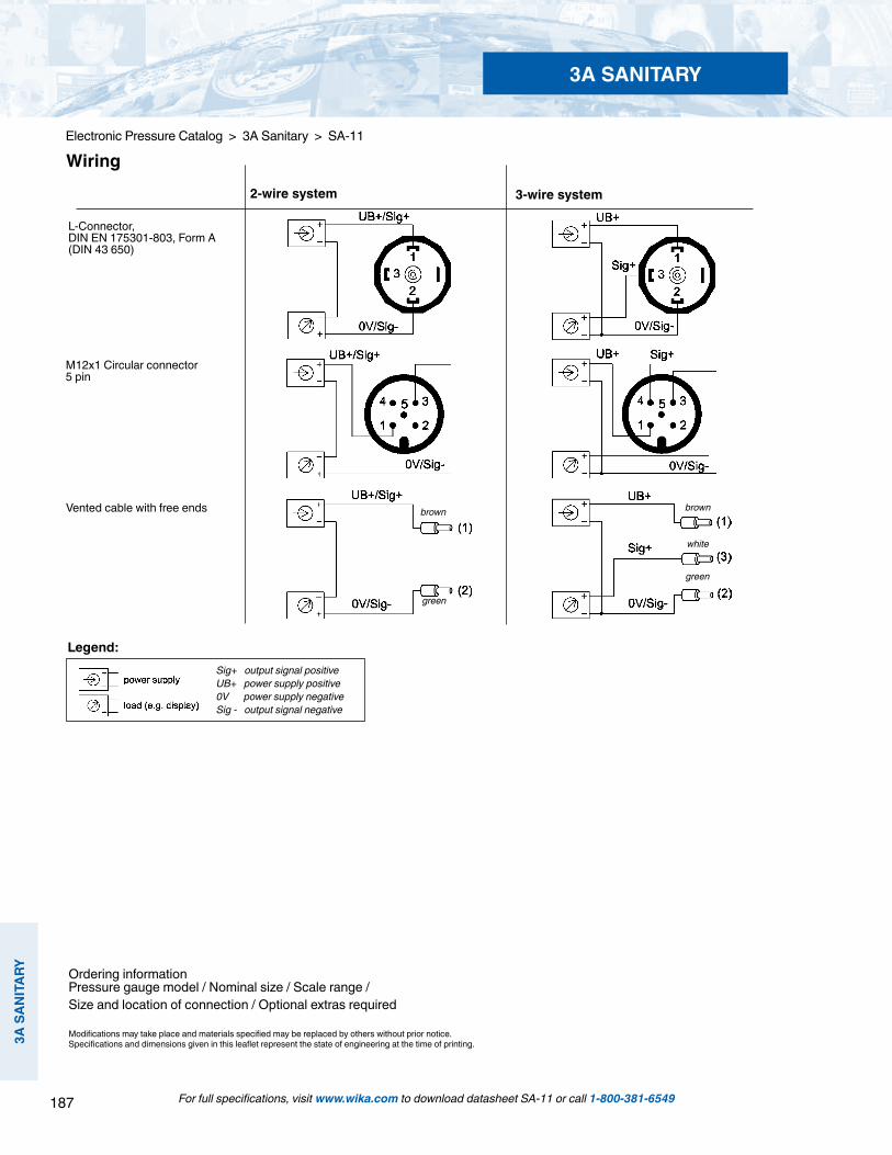
187
3A S
ANIT
ARY
3A SANITARY
For full specifications, visit www.wika.com to download datasheet SA-11 or call 1-800-381-6549
Electronic Pressure Catalog > 3A Sanitary > SA-11
Ordering informationPressure gauge model / Nominal size / Scale range / Size and location of connection / Optional extras required
Modifications may take place and materials specified may be replaced by others without prior notice.Specifications and dimensions given in this leaflet represent the state of engineering at the time of printing.
Legend:
L-Connector, DIN EN 175301-803, Form A(DIN 43 650)
Wiring
M12x1 Circular connector5 pin
3-wire system2-wire system
Vented cable with free ends brownbrown
green
white
green
Sig+ output signal positiveUB+ power supply positive0V power supply negativeSig - output signal negative
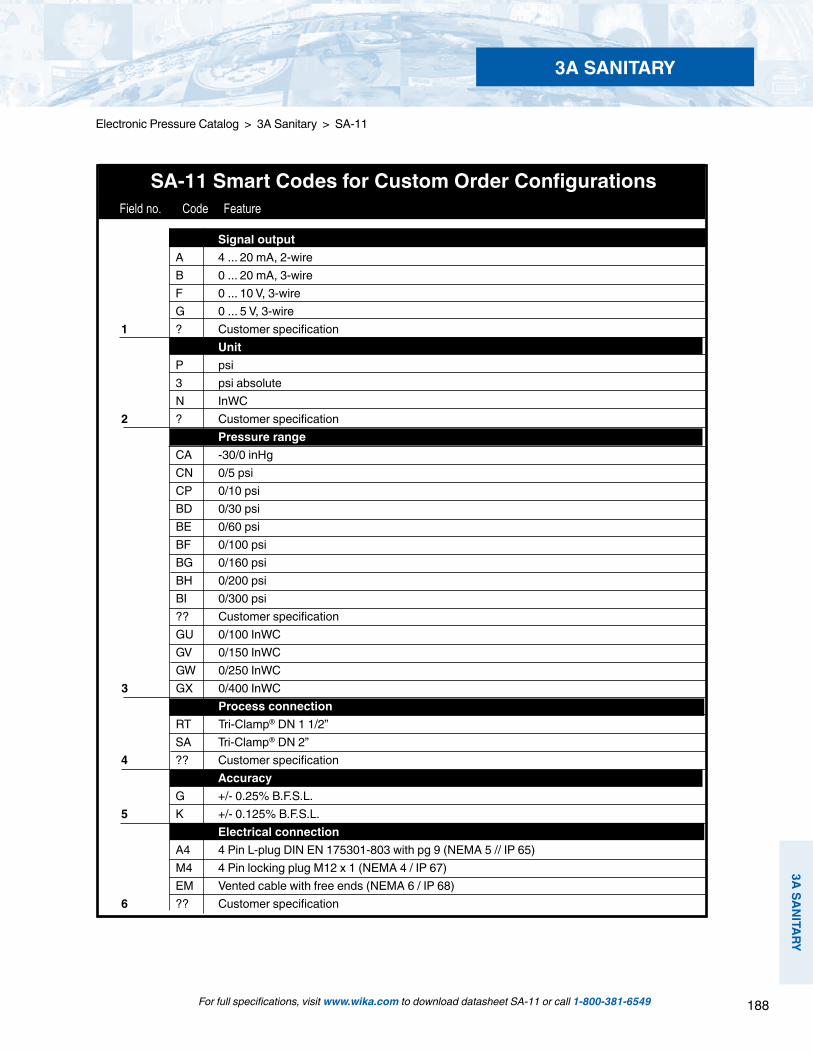
188
3A SANITARY
3A SANITARY
SA-11 Smart Codes for Custom Order Configurations Field no. Code Feature
Signal output A 4 ... 20 mA, 2-wire B 0 ... 20 mA, 3-wire F 0 ... 10 V, 3-wire G 0 ... 5 V, 3-wire 1 ? Customer specification Unit P psi 3 psi absolute N InWC 2 ? Customer specification Pressure range CA -30/0 inHg CN 0/5 psi CP 0/10 psi BD 0/30 psi BE 0/60 psi BF 0/100 psi BG 0/160 psi BH 0/200 psi BI 0/300 psi ?? Customer specification GU 0/100 InWC GV 0/150 InWC GW 0/250 InWC 3 GX 0/400 InWC Process connection RT Tri-Clamp® DN 1 1/2” SA Tri-Clamp® DN 2” 4 ?? Customer specification Accuracy G +/- 0.25% B.F.S.L. 5 K +/- 0.125% B.F.S.L. Electrical connection A4 4 Pin L-plug DIN EN 175301-803 with pg 9 (NEMA 5 // IP 65) M4 4 Pin locking plug M12 x 1 (NEMA 4 / IP 67) EM Vented cable with free ends (NEMA 6 / IP 68) 6 ?? Customer specification
For full specifications, visit www.wika.com to download datasheet SA-11 or call 1-800-381-6549
Electronic Pressure Catalog > 3A Sanitary > SA-11
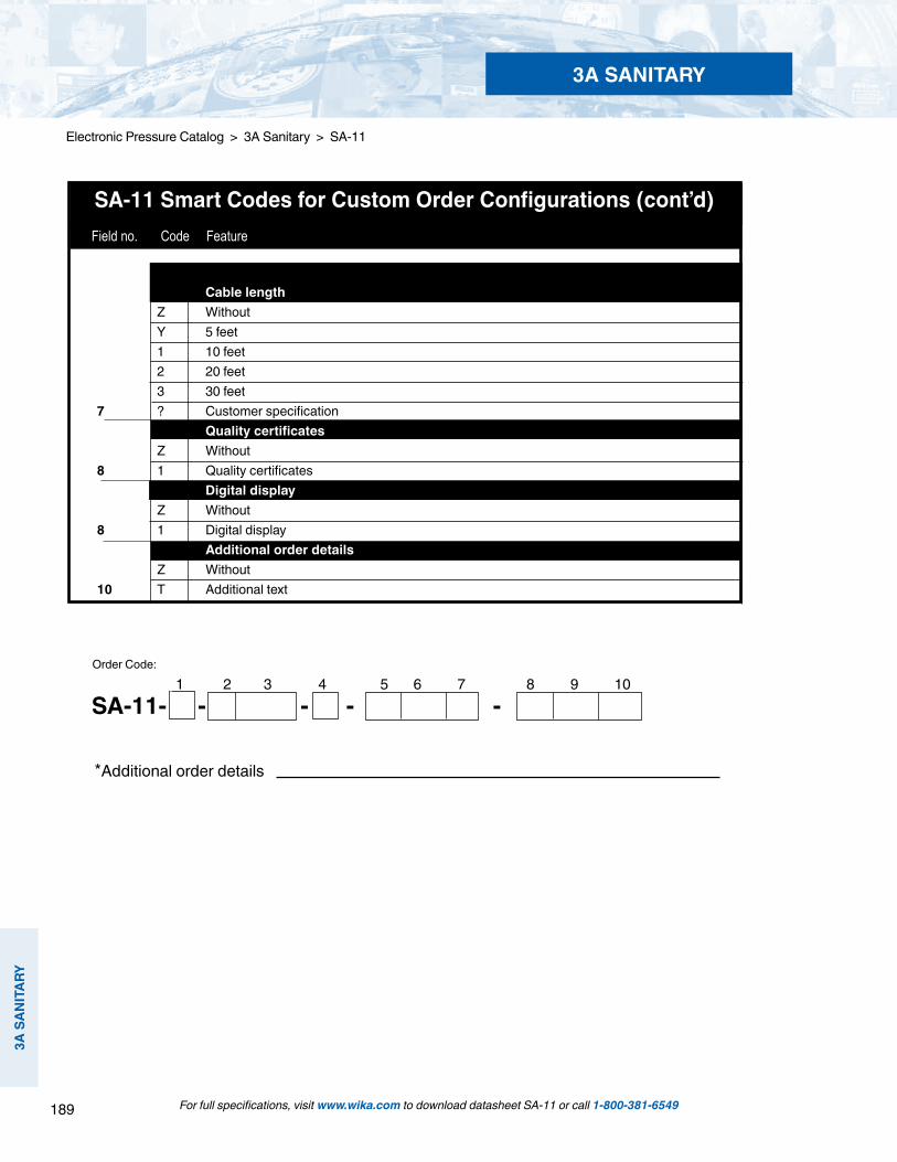
189
3A S
ANIT
ARY
3A SANITARY
SA-11 Smart Codes for Custom Order Configurations (cont’d) Field no. Code Feature
Cable length Z Without Y 5 feet 1 10 feet 2 20 feet 3 30 feet 7 ? Customer specification Quality certificates Z Without 8 1 Quality certificates Digital display Z Without 8 1 Digital display Additional order details Z Without 10 T Additional text
For full specifications, visit www.wika.com to download datasheet SA-11 or call 1-800-381-6549
Electronic Pressure Catalog > 3A Sanitary > SA-11
1 2 3 4 5 6 7 8 9 10
*Additional order details
Order Code:
SA-11- - - - -
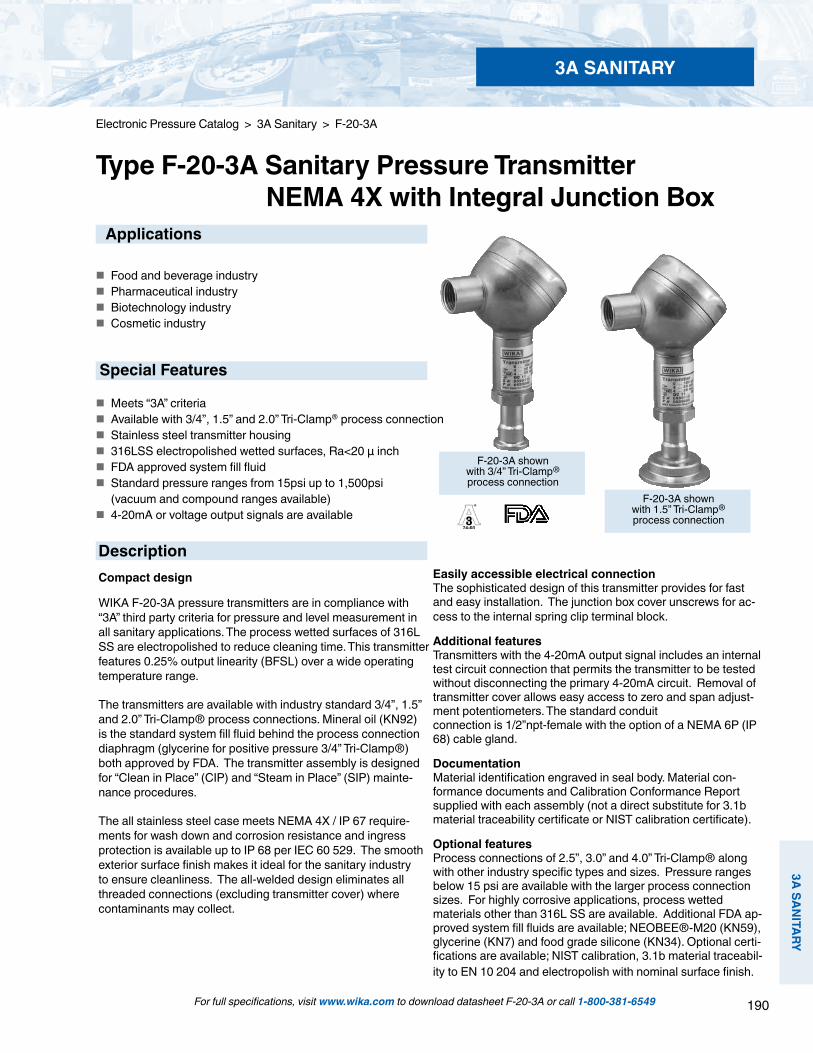
190
3A SANITARY
3A SANITARY
For full specifications, visit www.wika.com to download datasheet F-20-3A or call 1-800-381-6549
Electronic Pressure Catalog > 3A Sanitary > F-20-3A
Type F-20-3A Sanitary Pressure Transmitter NEMA 4X with Integral Junction Box
Easily accessible electrical connectionThe sophisticated design of this transmitter provides for fast and easy installation. The junction box cover unscrews for ac-cess to the internal spring clip terminal block.
Additional featuresTransmitters with the 4-20mA output signal includes an internal test circuit connection that permits the transmitter to be tested without disconnecting the primary 4-20mA circuit. Removal of transmitter cover allows easy access to zero and span adjust-ment potentiometers. The standard conduit connection is 1/2”npt-female with the option of a NEMA 6P (IP 68) cable gland.
DocumentationMaterial identification engraved in seal body. Material con-formance documents and Calibration Conformance Report supplied with each assembly (not a direct substitute for 3.1b material traceability certificate or NIST calibration certificate).
Optional featuresProcess connections of 2.5”, 3.0” and 4.0” Tri-Clamp® along with other industry specific types and sizes. Pressure ranges below 15 psi are available with the larger process connection sizes. For highly corrosive applications, process wetted materials other than 316L SS are available. Additional FDA ap-proved system fill fluids are available; NEOBEE®-M20 (KN59), glycerine (KN7) and food grade silicone (KN34). Optional certi-fications are available; NIST calibration, 3.1b material traceabil-ity to EN 10 204 and electropolish with nominal surface finish.
F-20-3A shown with 3/4” Tri-Clamp®process connection
F-20-3A shown with 1.5” Tri-Clamp®process connection
Applications
Food and beverage industry Pharmaceutical industry Biotechnology industry Cosmetic industry
Special Features
Meets “3A” criteria Available with 3/4”, 1.5” and 2.0” Tri-Clamp® process connection Stainless steel transmitter housing 316LSS electropolished wetted surfaces, Ra<20 µ inch FDA approved system fill fluid Standard pressure ranges from 15psi up to 1,500psi (vacuum and compound ranges available) 4-20mA or voltage output signals are available
DescriptionCompact design
WIKA F-20-3A pressure transmitters are in compliance with “3A” third party criteria for pressure and level measurement in all sanitary applications. The process wetted surfaces of 316L SS are electropolished to reduce cleaning time. This transmitter features 0.25% output linearity (BFSL) over a wide operating temperature range.
The transmitters are available with industry standard 3/4”, 1.5” and 2.0” Tri-Clamp® process connections. Mineral oil (KN92) is the standard system fill fluid behind the process connection diaphragm (glycerine for positive pressure 3/4” Tri-Clamp®) both approved by FDA. The transmitter assembly is designed for “Clean in Place” (CIP) and “Steam in Place” (SIP) mainte-nance procedures.
The all stainless steel case meets NEMA 4X / IP 67 require-ments for wash down and corrosion resistance and ingress protection is available up to IP 68 per IEC 60 529. The smooth exterior surface finish makes it ideal for the sanitary industry to ensure cleanliness. The all-welded design eliminates all threaded connections (excluding transmitter cover) where contaminants may collect.
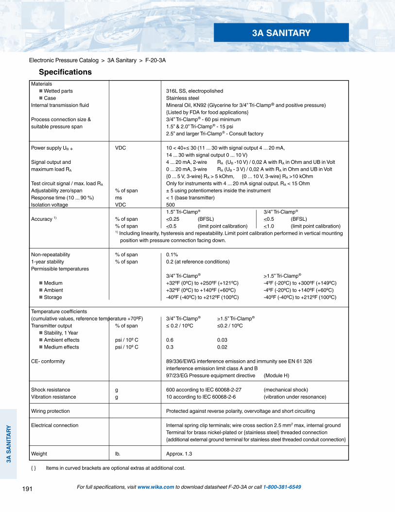
191
3A S
ANIT
ARY
3A SANITARY
For full specifications, visit www.wika.com to download datasheet F-20-3A or call 1-800-381-6549
Electronic Pressure Catalog > 3A Sanitary > F-20-3A
Specifications
Materials Wetted parts 316L SS, electropolished Case Stainless steelInternal transmission fluid Mineral Oil, KN92 (Glycerine for 3/4” Tri-Clamp® and positive pressure) Listed by FDA for food applicationsProcess connection size & 3/4” Tri-Clamp® - 60 psi minimum suitable pressure span 1.5” & 2.0” Tri-Clamp® - 15 psi 2.5” and larger Tri-Clamp® - Consult factory
Power supply UB + VDC 10 < 40+≤ 30 (11 ... 30 with signal output 4 ... 20 mA, 14 ... 30 with signal output 0 ... 10 V)Signal output and 4 ... 20 mA, 2-wire RA (UB -10 V) / 0,02 A with RA in Ohm and UB in Voltmaximum load RA 0 ... 20 mA, 3-wire RA (UB - 3 V) / 0,02 A with RA in Ohm and UB in Volt 0 ... 5 V, 3-wire RA > 5 kOhm, 0 ... 10 V, 3-wire RA >10 kOhmTest circuit signal / max. load RA Only for instruments with 4 ... 20 mA signal output. RA < 15 OhmAdjustability zero/span % of span ± 5 using potentiometers inside the instrumentResponse time (10 ... 90 %) ms < 1 (base transmitter)Isolation voltage VDC 500 1.5” Tri-Clamp® 3/4” Tri-Clamp®
Accuracy 1) % of span <0.25 (BFSL) <0.5 (BFSL) % of span <0.5 (limit point calibration) <1.0 (limit point calibration) 1) Including linearity, hysteresis and repeatability. Limit point calibration performed in vertical mounting position with pressure connection facing down.
Non-repeatability % of span 0.1%1-year stability % of span 0.2 (at reference conditions)Permissible temperatures 3/4” Tri-Clamp® >1.5” Tri-Clamp®
Medium +32ºF (0ºC) to +250ºF (+121ºC) -4ºF (-20ºC) to +300ºF (+149ºC) Ambient +32ºF (0ºC) to +140ºF (+60ºC) -4ºF (-20ºC) to +140ºF (+60ºC) Storage -40ºF (-40ºC) to +212ºF (100ºC) -40ºF (-40ºC) to +212ºF (100ºC)
Temperature coefficients (cumulative values, reference temperature +70ºF) 3/4” Tri-Clamp® >1.5” Tri-Clamp®
Transmitter output % of span ≤ 0.2 / 10ºC ≤0.2 / 10ºC Stability, 1 Year Ambient effects psi / 10º C 0.6 0.03 Medium effects psi / 10º C 0.3 0.02
CE- conformity 89/336/EWG interference emission and immunity see EN 61 326 interference emission limit class A and B 97/23/EG Pressure equipment directive (Module H)
Shock resistance g 600 according to IEC 60068-2-27 (mechanical shock)Vibration resistance g 10 according to IEC 60068-2-6 (vibration under resonance)
Wiring protection Protected against reverse polarity, overvoltage and short circuiting
Electrical connection Internal spring clip terminals; wire cross section 2.5 mm2 max, internal ground Terminal for brass nickel-plated or stainless steel threaded connection additional external ground terminal for stainless steel threaded conduit connection
Weight lb. Approx. 1.3
Items in curved brackets are optional extras at additional cost.
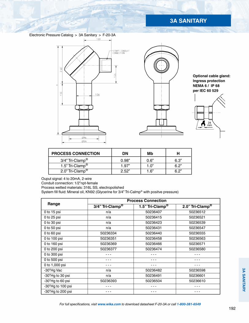
192
3A SANITARY
3A SANITARY
For full specifications, visit www.wika.com to download datasheet F-20-3A or call 1-800-381-6549
Electronic Pressure Catalog > 3A Sanitary > F-20-3A
Optional cable gland:Ingress protectionNEMA 6 / IP 68per IEC 60 529
PROCESS CONNECTION DN Mb H 3/4” Tri-Clamp® 0.98” 0.6” 6.3” 1.5” Tri-Clamp® 1.97” 1.0” 6.2” 2.0” Tri-Clamp® 2.52” 1.6” 6.2”
24 mm
Range
Process Connection 3/4” Tri-Clamp® 1.5” Tri-Clamp® 2.0” Tri-Clamp®
0 to 15 psi n/a 50236407 502365120 to 25 psi n/a 50236415 502365210 to 30 psi n/a 50236423 502365390 to 50 psi n/a 50236431 502365470 to 60 psi 50236334 50236440 502365550 to 100 psi 50236351 50236458 502365630 to 160 psi 50236369 50236466 502365710 to 200 psi 50236377 50236474 502365800 to 300 psi - - - - - - - - -0 to 500 psi - - - - - - - - -0 to 1,000 psi - - - - - - - - --30”Hg Vac n/a 50236482 50236598-30”Hg to 30 psi n/a 50236491 50236601-30”Hg to 60 psi 50236393 50236504 50236610-30”Hg to 100 psi - - - - - - - - --30”Hg to 200 psi - - - - - - - - -
Ouput signal: 4 to 20mA, 2-wire Conduit connection: 1/2”npt-female Process wetted materials: 316L SS, electropolished System fill fluid: Mineral oil, KN92 (Glycerine for 3/4” Tri-Calmp® with positve pressure)

193
3A S
ANIT
ARY
3A SANITARY
For full specifications, visit www.wika.com to download datasheet F-20-3A or call 1-800-381-6549
Electronic Pressure Catalog > 3A Sanitary > F-20-3A
Legend:
Sig+ output signal positiveUB+ power supply positive0V power supply negativeSig - output signal negative
Wiring
3-wire system2-wire system

194
3A SANITARY
3A SANITARY
For full specifications, visit www.wika.com to download datasheet F-20-3A or call 1-800-381-6549
Electronic Pressure Catalog > 3A Sanitary > F-20-3A
F-20-3A Smart Codes for Custom Order Configurations Field no. Code Feature
Signal output 4 ... 20 mA, 2-wire 0 …10 V, 3-wire (Supply 14-30 V) 0 ... 5 V, 3-wire 1 Other - please specify Units psi InWC 2 Other - please specify Pressure range -30 inHg … 0 1
-30 inHg …30 psi 1 -30 inHg …60 psi -30 inHg …100 psi -30 inHg …160 psi -30 inHg …200 psi 0 InWC … 50 InWC 1, 2
0 InWC … 100 InWC 1, 2
0 psi … 5 psi 1, 2
0 psi … 10 psi 1, 2
0 psi … 15 psi 1
0 psi … 30 psi 1 0 psi … 60 psi 0 psi … 100 psi 0 psi … 160 psi 0 psi … 200 psi 0 psi … 300 psi 0 psi … 400 psi 0 psi … 500 psi 0 psi … 600 psi 0 psi … 750 psi 0 psi … 1,000 psi 3 0 psi … 1,500 psi Process connection ¾” Tri-Clamp® 1½” Tri-Clamp®
2.0” Tri-Clamp®
2½” Tri-Clamp®
3.0” Tri-Clamp®
4.0” Tri-Clamp® Other - please specify

195
3A S
ANIT
ARY
3A SANITARY
For full specifications, visit www.wika.com to download datasheet F-20-3A or call 1-800-381-6549
Electronic Pressure Catalog > 3A Sanitary > F-20-3A
Notes: (1) Not available with ¾” Tri-Clamp® process connection (2) Consult WIKA for suitable process connection size (3) Not recommended for vacuum or compound pressure ranges (4) Standard offering for ¾” Tri-Clamp® with positive pressure ranges
F-20-3A Smart Codes for Custom Order Configurations (cont’d) Field no. Code Feature
Material of wetted parts 316L SS (1.4435) electropolished Hastelloy® C276 (2.4819) PFA coated 316L SS (FDA approved) 4 Other - please specify System Fill fluid KN 7 - Glycerine (note 3 & 4) KN 93 - Food grade silicone oil (note 3) KN 59 - NEOBEE® M20 KN 92 - Mineral oil (liquid paraffin) 5 Other - please specify Electrical connection ½” NPT female conduit (IP 67) Stainless steel cable gland (IP 68) 6 Other - please specify Quality certificates Without Certificate - electropolish w/ nominal surface finish Certificate - EN 10 204 3.1B (material traceable) Certiifcate of Compliance (C of C) Certificate - NIST calibration 7 Other - please specify Additional order details Without Additional text

196
Electronic Pressure Catalog > Notes
NOTES
NOTES:

Electronic Product Catalog

WIKA Instrument, LP1000 Wiegand BoulevardLawrenceville, GA 30043Toll Free 1-800-381-6549Tel (770) 513-8200 Fax (770) [email protected] • www.wika.com/tronicTC11 - 3,000 03/13 © Copyright 2013 WIKA Instrument, LP All Rights Reserved
R
With almost 70 years of experience, WIKA Instrument, LP is the leading global manufacturer of pressure and temperature measurement instrumentation, producing more than 43 million pressure gauges, diaphragm seals, pressure transmitters, thermometers and other instruments annually. WIKA’s extensive product line, including mechanical and electronic instruments, provides measurement solutions for any application in a large variety of industries. A global leader in lean manufacturing and instrumentation experience, WIKA also offers a broad selection of stock and custom instrumentation as well as dedicated services to provide customers with the right solutions, at the right time, wherever they need us.
WIKA provides distinctive service and support to our channel partners and customers:• Award winning U.S.-based manufacturing, sales and ordering customer service and technical support • Certified technical specialists who conduct Best Practice Instrument Reviews with performance improvement reports• An in-house engineering team for product customization and innovation • Proven capabilities to connect with customer business processes for ordering and inventory management • Web-based customer service features, including RFQs, literature request and competitor product cross reference
General Purpose Pressure Transmitter
S-10
Explosion-proof Pressure Transmitter
E-11