ELECTRONIC - II - II 4th sem.pdf · Clipper and Clamper circuit •Clipper circuit : It helps in...
29
ELECTRONIC - II
Transcript of ELECTRONIC - II - II 4th sem.pdf · Clipper and Clamper circuit •Clipper circuit : It helps in...

ELECTRONIC - II

Chapter – 1.Transistor Audio Power Amplifier
A transistor amplifier which raises the power level of the signals that have audio frequency range is known as transistor audio power amplifier.

Difference between voltage and power amplifier.
Voltage amplifier
• Voltage amplifier is used to raise voltage level of weak signal.
• No need of heat sink in voltage amplifier.
• Distortion in output will be minimum.
• Size of transistor used is small.
• RC coupling is widely used.
• Used as first stage of amplifier.
• Output impedance is high.
Power amplifier
• Power amplifier is used to raise power level of weak signal.
• Heat sink are used in power amplifier.
• Distortion in output will be minimum.
• Size of power transistor is large.
• Transformer coupling is widely used.
• Used as last stage of amplifier.
• Output impedance is low.

Important terms of Power Aamplifier
• Collector efficiency : The ratio of ac output power to
the dc input power or zero signal power of a power amplifier is known as collector efficiency.
• Distortion : The change of output wave shape from the
input wave shape of an amplifier is known as distortion.
• Power dissipation capability : The ability of a power
transistor to dissipate heat developed in it during operation is
known as dissipation capability.

Classification of power amplifiers
1. Class A power amplifier2. Class B power amplifier3. Class C power amplifier4. Class AB power amplifier
1. If the collector current flows at all time during the full cycle of signal, the power amplifier is called class A power amplifier.
2. If the collector current flows during the positive half cycle of input supply is called class B power amplifier.
3. If the collector current flows for less than half cycle of input supply is called class C power amplifier.
4. If the collector current flows for more than half cycle is called class AB power amplifier.

Heat sink in power amplifiers
• Power amplifier handle large amount of current. Because of heavy current, transformers are heated up during operation. So excessive heat is to be dissipated. The device used for this purpose is called heat sink.
Heat sink is just a sheet of metal which improve the heat dissipation of power transistor.

Chapter – 2Tuned Voltage Amplifier
• Tuned Voltage Amplifier Tuned voltage amplifier is used to amplify the weak signal to a particular tuned freq. It uses a tuned parallel circuit i.e. a parallel resonance circuit is employed as a load in the collector. When input signal of different frequencies are used or applied at input terminal, the amplifier selects single frequency to which it is tuned and amplifies it. It rejects all other frequency and hence amplifies the weak signal selected.

Advantages of tuned voltage amplifier
• Smaller power loss : Tuned voltage amplifier employs
smaller power loss.
• High Selectivity : Tuned amplifier selects high selectivity.
• Smaller collector supply voltage : It requires small
Vcc.

Applications of tuned amplifier
• Due to high selectivity, high gain and required bandwidth.
• Employed in TV receiver.
• Radio receiver.
• Portable system.

Double Tuned Voltage amplifier
• To obtain high selectivity, high gain and required bandwidth, double-tuned voltage amplifiers are used. The main disadvantage of single tuned voltage amplifier i.e. low bandwidth and undesirable attenuation are overcome by using double tuned voltage amplifier.

Chapter – 3Feedback in Amplifiers
• Feedback : The process in which a part of output energy is
feeding back to input is called feedback.
• Types of feedback.1. +ve feedback
2. -ve feedback1. When feed back energy is in phase with the input signal is
known as +ve feedback. It is also known as direct or regenerative feedback.
2. When feedback energy is out of phase or 180 phase shift with the input signal is known as -ve feedback. It is also known as indirect or reverse feedback.

Advantages and Disadvantages of –vefeedback
Advantages• Highly stabilized gain
• Reduced Distortion
• Reduced Noise
• Increased Bandwidth
• Increased Input impedance
• Reduced output impedance
DisadvantagesWhen –ve feedback signal is used, gain reduced by a factor
1/1+AB

Emitter Follower Amplifier
• Emitter follower is also called common collector amplifier because collector is common between input and output of circuit. As circuit input resistance is high, therefore. It avoids loading of previous stage of amplifier.

Applications of Emitter follower
• It is used as buffer amplifier in between two stages for impedance matching purpose.
• It is used for the purpose of reduction in noise at the receiver kit.
• It is used as isolator in electronic circuit.

Chapter – 4Sinusoidal Oscillator
• Oscillator : Oscillator is an electronic device which
generates oscillations of desired frequency is called oscillator. These can generate signal of frequency from few Hz to MHz.
• Essentials of an oscillatorAn oscillator circuit must contain ;
1. Frequency determining network
2. Properly biased amplifier to boost the oscillator
3. Feedback network.

Difference between oscillator and alternator.
Oscillator• An oscillator is an non rotating
device have very little wear & tear
• It has longer life and high efficiency.
• In operation an oscillator is quite silent.
• Oscillators are smaller in size and lower in cost.
• It has better frequency stability.
• The operation of an oscillator is very easy portable.
Alternator
• An alternator is a rotating device.
• It has shorter life and poor efficiency.
• In operation of an alternator is noisy.
• Alternators are higher in cost.
• It has poor frequency stability.
• The operation of an alternator is difficult and difficult to port.
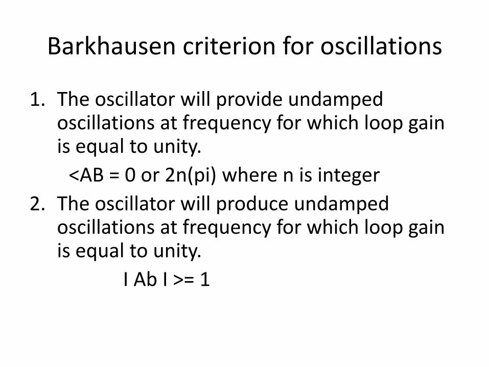
Barkhausen criterion for oscillations
1. The oscillator will provide undampedoscillations at frequency for which loop gain is equal to unity.
<AB = 0 or 2n(pi) where n is integer
2. The oscillator will produce undampedoscillations at frequency for which loop gain is equal to unity.
I Ab I >= 1
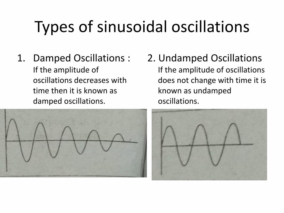
Types of sinusoidal oscillations
1. Damped Oscillations : If the amplitude of oscillations decreases with time then it is known as damped oscillations.
2. Undamped Oscillations If the amplitude of oscillations does not change with time it is known as undampedoscillations.

Chapter – 5 Wave Shaping and Switching Circuits
• Wave shapes circuit is used to change shape of waveform to the desired shape. They are of two types.
1. Linear Waveshaper : These waveshapers have positive components such as R, L & C. The basic property of circuit is that they don’t change the shape of waveform. Ex. are LPF, HPF, attenuator.
2. Non-Linear Waveshaper : The circuit consist of R, L, C diode and zener diode,. The basic property of circuit is that the output will not be of same shape. Ex. are: clipper circuit, clamper circuit and comparator circuit.

Clipper and Clamper circuit
• Clipper circuit : It helps in removing either positive or
negative parts of waveform so that the voltage level is kept below the threshold limit. There are two types of clipper circuits. Positive clipper removes the positive part of the waveform and negative clipper removes the negative part.
• Clamper circuit : These circuits adds dc level to ac signal.
It shifts either the entire wave in positive side or in negative side. Two types of clampers are there. Positive clamper shifts the waveform towards positive side and negative clamper shifts the waveform towards negative side.

Transistor as a Switch
• Transistor can be employed as an electronic switch. To understand it’s working, considered a npntransistor. When transistor is used as a switch, it is operator in cut off and saturation region.
• Cutoff region :-When the input base voltage is zero or negative, the transistor is said to be in the OFF condition. In this condition, base current Ib = 0 and collector current is equal to ICEO.
• Saturation region :- When the input base voltage is positive, the transistor is said to be in the ON condition.

Multivibrator and it’s applications
• An electronic circuit that generates square waves is called a multivibrators.
Applications1. It is used to generate square wave and pulse
generate.2. It is used as frequency dividers.3. It is used as standard frequency source.4. It can be used as generation of time delays.5. It is used in radar and TV circuits. 6. It is also used as memory elements in computer.

Chapter – 6Power Supplies
• Regulated Power SupplyA dc power supply that maintains the output voltage
constant irrespective of the fluctuations in ac mains or variations in load is known as a regulated power supply.

Distinction between CVT and Stabilizer
CVT1. Its input voltage is 170-270V
at 50 Hz and output voltage is 230 V + 2V.
2. At 1000 V, insulation is more than 500 mega ohms in CVT.
3. Its efficiency is more than 85 percent.
4. It is used mostly with PCs.5. CVT have more weight, large
size and more cost.6. More life as no maintenance
is required in CVT.
Stabilizer1. Its input voltage lies between
140-270 V and output voltage lies between 195-235 V.
2. No isolation at all, Very little protection is provided.
3. Its efficiency is 70-75 percent.4. It is used in house appliance
such as refrigerator, TV etc.5. Stabilizer have lower weight,
smaller size and less cost.6. In stabilizer, very less life as
moving parts are deteriorate qu

SMPSSwitched Mode Power Supply
• SMPS supply provides constant dc voltage. It is widely used in computer system, television, receivers, VCR etc. SMPS supplies are smaller and light in weight as compared to other regulated power supplies. The power dissipation is minimum as compared of other supplies. Therefore efficiency is quite high.

Advantages and Disadvantages
• Advantages1. Switching device are electronic switches such as
transistor, MOSFET, there are ON OFF devices. Power dissipation is minimum.
2. Efficiency of SMPS is higher.3. SMPS can even operate under low as voltage.
Disadvantages1. In SMPS, electromagnetic interference is produced
from ON/OFF of electronic switches.2. SMPS power supplies are complex .3. The control circuit is expensive and less relisble

Chapter – 7 Operation Amplifier
• Operational amplifier is direct-coupled high gain amplifier. As shown in block diagram, it consists of following stages :
1. Two stage differential amplifier.
2. Level translator.
3. Push pull amplifier.

Ideal Operational Amplifier
• Ideal operational amplifier has following characteristics :
1. Infinite open loop gain.2. Infinite input impedance.3. Zero output resistance.4. Infinite common mode rejection Ratio (CMRR).5. Infinite bandwidth.6. Infinite slew rate i.e. output should respond
simultaneously to variation in input.7. Zero offset voltage.8

Applications
1. Summing and Subtractor op – Amp
2. Differentiator and integrator
3. Analog to digital converter
4. Digital to analog converter
5. Voltage clamper.