Electronic Home Music Reproducing Equipment
14
Electronic Home Music Reproducing Equipment Daniel R von Recklinghausen Copyright © 1977 by the Audio Engineering Society. Reprinted from the Journal of the Audio Engineering Society, 1977 October/November, pages 759...771. This material is posted here with permission of the AES. Internal or personal use of this material is permitted. However, permission to reprint/republish this material for advertising or promotional purposes or for creating new collective works for resale or redistribution must be obtained from the AES by contacting the Managing Editor, William McQuaid., [email protected]. By choosing to view this document, you agree to all provisions of the copyright laws protecting it. John G. (Jay) McKnight, Chair AES Historical Committee 2005 Nov 07
Transcript of Electronic Home Music Reproducing Equipment

Electronic Home Music ReproducingEquipment
Daniel R von Recklinghausen
Copyright © 1977 by the Audio Engineering Society. Reprinted from the Journal of the AudioEngineering Society, 1977 October/November, pages 759...771.
This material is posted here with permission of the AES. Internal or personal use of this materialis permitted. However, permission to reprint/republish this material for advertising or promotionalpurposes or for creating new collective works for resale or redistribution must be obtained from theAES by contacting the Managing Editor, William McQuaid., [email protected].
By choosing to view this document, you agree to all provisions of the copyright laws protecting it.
John G. (Jay) McKnight, ChairAES Historical Committee2005 Nov 07
Electronic Home Music ReproducingEquipment
DANIEL R. VON RECKLINGHAUSEN
Arlington, MA
The search for amplification and control of recorded and transmitted music over the last100 years has progressed from mechanical amplifiers to tube amplifiers to solid-stateequipment. The AM radio, the record player, the FM receiver, and the tape recorder havesupplemented the acoustical phonograph and the telephone. An incomplete summary ofimportant developments in the past is presented along with challenges for the future.
Home music reproduction began when Bell invented the tromechanical repeater caused it to be used for 20 yearstelephone in 1876 and Edison invented the phonograph in more as a hearing-aid amplifier [5, pp. 64-69].1877. Instruments were manufactured soon thereafter and C.A. Parsons of London, England, inventor of theleased or sold to the public. Yet the listener had very little Auxetophone, marketed in 1907 a phonograph where thecontrol over the reproduction and the volume of sound, the playback stylus vibration caused a valve to modulate a
tone quality being predetermined by the manufacturer of stream of compressed air which was fed to a reproducingthe phonograph and record or by the telephone company horn [6]. Capable of great volume, but always having aand its equipment, backgroundhiss, the modulatedair stream loudspeakeris
A great deal of effort went into various means to still with us today as the only means of amplificationincrease the volume or to be able to hear sounds from a capable of producing extremely high sound pressuregreater distance. There was need for an amplifier, and levels.
various inventors devised methods that seemed to solve All these methods had the common problem describedtheproblem, in these days as "inertia." We now recognizethat the
Edison [1] coupled a telephone transmitter to the moving mass in all those devices was relatively high, andarmature of a telegraph relay in 1877. Hughes [2], writing an increase in high-frequency response required an in-"on the physical action of the microphone," described the crease in driving power, which was just not available.accidental discovery of the "howling telephone" when he Equalization of frequency response was possible only byplaced both the transmitter and the receiver on a wooden empirical means.
sounding board, thereby having found something which Even radio broadcasting existed in the preelectronicprovided a "relay" for the human voice in telephony, days. In 1902 Pickard succeeded in transmitting intelligi-Numerous other inventors improved upon this elec- ble speech by radio, using an 8-10-kHz spark transmittertromechanical amplifier, notably H.W. Shreeve [3] of the as source and a carbon microphone in the antenna lead as a
Western Electric Company. The Shreeve repeater was modulator [5, p. 39]. Successful broadcasting of speechreliable enough to qualify for commercial telephone ser- and music was conducted by Fessenden [7] at Brant Rock,vice in toll telephone circuits (New York-Chicago 1904) Massachusetts, on December 24, 1906, using a 1-kWand even saw service in the first transcontinental telephone 50-kHz alternator built by the General Electric Companyservice [4] inaugurated on January 25, 1915. The compact under the direction of E. F. W. Alexanderson. Modulation
size and relatively modest power needs of the elec- was accomplished by a watercooled carbon microphone in
OCTOBER/NOVEMBER1977,VOLUME25,NUMBER10/11 759
DANIEL R. VON RECKLINGHAUSEN
the antenna ground lead. Clear reception was obtained at signal was impressed--each tube was different. However,many locations, including ships at sea. In the following starting in 1912, both the General Electric Company andyears an increasing number of transmitters were built, the Western Electric Company had learned to makesome of them arc transmitters. One essential tool in these uniform well evacuated tubes [13].stations was a mallet, used to free the carbon granules in The triode tube was not only capable of detecting radio
the microphone when they had become stuck by overheat- signals, but it was able to amplify audio signals as well. Ining [9]. 1912the FederalTelegraphCompany[14]demonstrated
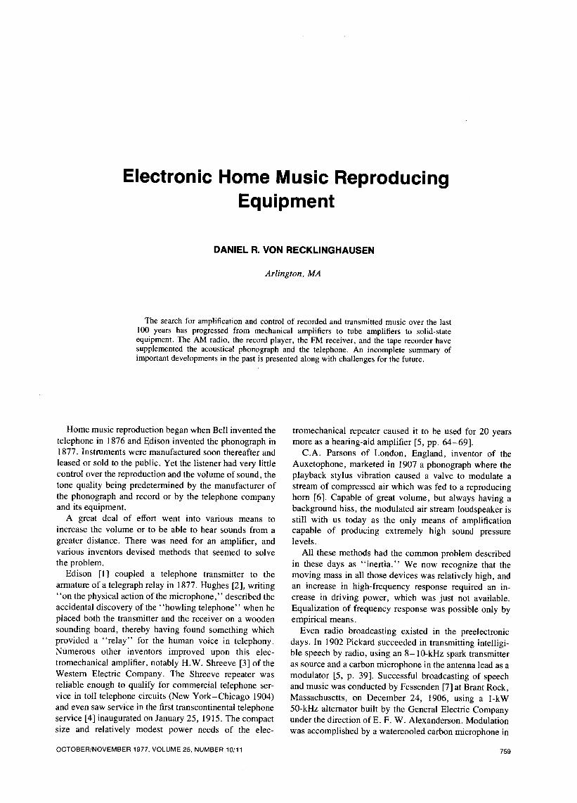
It is probable that not only electrolytic detectors were to the U.S. Navy the first commercial cascade audioused for reception, but also the first solid-state detectors frequency amplifier (Fig. 1). Containing three DeForest[8], the first crystal detector having been invented by Audions, tests made at that time indicated that the am-Pickard in 1906. It consisted of a silicon crystal and a plifier increased the received signal in intensity by 120
catwhisker. Dunwoody's detector of about the same time times.consisted of a carborundum crystal clamped between two Other research with tubes continued throughout thebrass holders. Most likely a Marconi magnetic detector pre-World War I period [15]. Almost simultaneously fourwould be used, connected in series with a set of magnetic inventors (DeForest, Armstrong, and Langmuir in the
headphones. These receiving sets eventually became United States and Meissner in Germany) independentlyknown as crystal sets and became very popular. _ discovered (in the 1911-1912 period) the increased re-
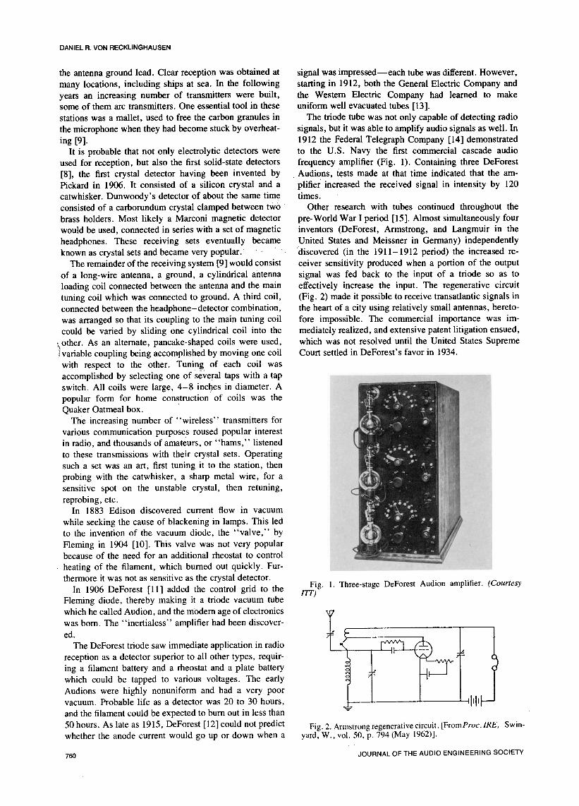
The remainder of the receiving system [9] would consist ceiver sensitivity produced when a portion of the outputof a long-wire antenna, a ground, a cylindrical antenna signal was fed back to the input of a triode so as toloading coil connected between the antenna and the main effectively increase the input. The regenerative circuittuning coil which was connected to ground. A third coil, (Fig. 2) made it possible to receive transatlantic signals inconnected between the headphone-detector combination, the heart of a city using relatively small antennas, hereto-was arranged so that its coupling to the main tuning coil fore impossible. The commercial importance was im-could be varied by sliding one cylindrical coil into the mediately realized, and extensive patent litigation ensued,
i other. As an alternate, pancake-shaped coils were used, which was not resolved until the United States Supreme!variable coupling being accomplished by moving one coil Court settled in DeForest's favor in 1934.
with respect to the other. Tuning of each coil wasaccomplished by selecting one of several taps with a tapswitch. All coils were large, 4-8 inches in diameter. Apopular form for home construction of coils was theQuaker Oatmeal box.
The increasing number of "wireless" transmitters for
various communication purposes roused popular interestin radio, and thousands of amateurs, or "hams," listenedto these transmissions with their crystal sets. Operatingsuch a set was an art, first tuning it to the station, thenprobing with the catwhisker, a sharp metal wire, for asensitive spot on the unstable crystal, then retuning,
reprobing, etc.In 1883 Edison discovered current flow in vacuum
while seeking the cause of blackening in lamps. This ledto the invention of the vacuum diode, the "valve," by
Fleming in 1904 [10]. This valve was not very popularbecause of the need for an additional rheostat to control
heating of the filament, which burned out quickly. Fur-thermore it was not as sensitive as the crystal detector.
Fig. 1. Three-stage DeForest Audion amplifier. (CourtesyIn 1906 DeForest [11] added the control grid to the ITl')
Fleming diode, thereby making it a triode vacuum tube
whichhecalledAudi°ri'andthem°demage°f electr°nics t It
was bom. The "inertialess" amplifier had been discover-
ed. ?
The DeForest triode saw immediate application in radio 1 tFiiv_ ____i_
reception as a detector superior to all other types, requir-ing a filament battery and a rheostat and a plate batterywhich could be tapped to various voltages. The earlyAudions were highly nonuniform and had a very poorvacuum. Probable life as a detector was 20 to 30 hours, Illl_
?
and the filament could be expected to burn out in less than
50 hours. As late as 1915, DeForest [12] could not predict Fig. 2. Armstrongregenerative circuit. [FromProc.IRE, Swin-whether the anode current would go up or down when a yard, W., vol. 50, p. 794 (May 1962)].
760 JOURNAL OF THE AUDIO ENGINEERING SOCIETY
HOME MUSIC REPRODUCING EQUIPMENT
The triode tube could also amplify high-frequency radio whose functions were transferred to the Federal Com-. signals; however, its grid-plate capacitance was relatively munications Commission in 1934. On August 28, 1922high, and stable amplification was difficult to obtain until at '5:15 p.m. WEAF, New York, broadcasted the firstHazeltine [16] invented the neutrodyne circuit in 1918. commercially sponsored program [20] (QueensboroughHere a current obtained from the plate circuit was fed back Corporation, a real estate organization). The first chaininto the grid circuit in the proper magnitude and phase to broadcast on January 4, 1923, featured a telephone tieup be-balance out, or neutralize, the grid-plate capacitance tween WEAF, New York, and WNAC, Boston.inside the tube, thereby preventing oscillation and achiev- A few years later, radio broadcasting networks were
ing stability. ,organized:November1, 1926,the NationalBroadcastingRegenerative radio receivers reached the peak of their Company with WEAF and WJZ as key stations, and
popularity in 1922 and continued as a low-cost receiver for September 18, 1927, the Columbia Broadcasting Systemmany years thereafter. As late as 1940 a consortium of went on the air with a basic network of 16 stations.
manufacturers in Germany produced an ac-dc low-cost In Europe radio broadcasting progressed under muchradio _ containing two tubes, one triode-pentode as re- stricter government control; the stations were generallygenerative detector--power amplifier, and one power operated by the post office departments of the variousrectifier, countries.For example,the firstGermanbroadcaststation
The triode tube could also oscillate at radio frequencies [21] went on the air in 1923. In 1928 the "final" numberand van der Bijl [17] of the Western Electric Company of AM broadcast stations in Europe was reached bydiscovered that the improved triodes of 1913 had a international agreement with spacings every 9kHz. Fromsquare-law characteristic curve. He utilized the variable that time until the end of World War II the number ofslope to produce a modulated wave by' applying a small stations remained constant, and only the transmitter powerhigh-frequency signal and a relatively large modulating increased.signal voltage to the grid of the tube. The ATT Company The result of these diverging philosophies was thattransmitter, constructed according to this principle at the American sets ended up with dials marked only inNaval Station in Arlington, Virginia, in 1915, employed wavelength or frequency while European sets featured500 tubes in parallel as class-A amplifiers and was heard larger dials with the transmitter's location marked promi-as far awayas ParisandHonolulu. nently.
Soon thereafter various amateurs not satisfied with The direction of the radio receiver industry focusedreceiving signals decided also to transmit signals. The from its beginnings on increased performance and operat-laws of the United States in 1920 specified these ing convenience. Until 1927 all receivers used filament-wavelengths[18]: type triodes [13], the filamentA and plate B supply
voltages generally supplied by batteries. The early triodesHigh power stations over 1600 meters used the tungsten filament as the cathode without addi-Navy 600 to 1600 meters tional coating. To achieve electron emission, the filamentShip stations 300, 450, 600 meters had to be operated at white heat. Westem Electric coatedAmateurs below 200 meters the filaments with barium oxide and other oxides, enabling
tube operation with the filament heated only to red heat.One of these amateurs, Dr. Frank Conrad [19] of East
Of these tubes, the Western Electric VT-1 tube wasPittsburgh, Pennsylvania, built his amateur wireless sta- perhaps best known. During the beginning years oftion in 1916, obtaining call letters 8XK for it. In 1920 he broadcasting, the tube types 200, 201, and 202 high-converted his station to radio telephony and put on a vacuum triodes with tungsten filaments were available.two-hour program Wednesday and Saturday night. His
In 1923 the broadcast receiver business was flourishing,programs proved to be so popular that the supply of crystal crystal sets and regenerative sets providing most sales [8].sets in the local department store was soon sold out. The most famous sets were the Westinghouse Radiola, the
On October 27, i920, Conrad's station became thefirst in the world to be licensed as a commercial station. Clapp-Eastham, and the Grebe. Each of these receivers
had one detector and two stages of audio amplification.It began broadcasting with a power of 100 watts, using call These sets received ship signals on 600 m (500 kHz), theletters KDKA on November 2. broadcast frequencies of 485 m (619 kHz) and 360 m (833
In 1920 only one broadcast authorization was granted, kHz), and the "hams" on the short-wave band 200-250The next year 30 authorizations were given, assigned to
m (1200-1500 kHz). The frequency range of allthe wavelengths of 360 m or 833 kHz and 485 m or 619
"medium-wave" broadcast receivers has changed onlykHz. In 1922, 639 stations were authorized, in 1923, 239,and in 1924, 286. The additional wavelength authorized slightly since that time.
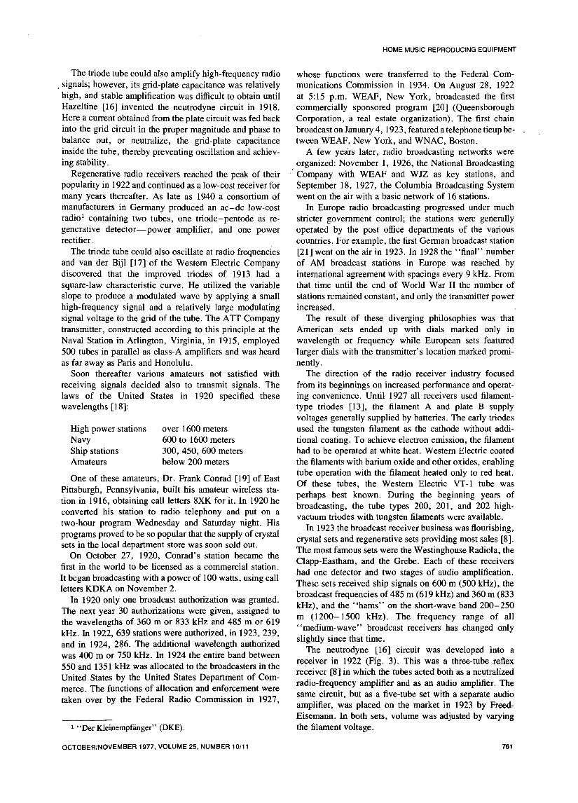
The neutrodyne [16] circuit was developed into awas 400 m or 750 kHz. In 1924 the entire band betweenreceiver in 1922 (Fig. 3). This was a three-tube reflex550 and 1351 kHz was allocated to the broadcasters in thereceiver [8] in which the tubes acted both as a neutralized
United States by the United States Department of Corn-radio-frequency amplifier and as an audio amplifier. Themerce. The functions of allocation and enforcement were
taken over by the Federal Radio Commission in 1927, same circuit, but as a five-tube set with a separate audioamplifier, was placed on the market in 1923 by Freed-Eisemann. In both sets, volume was adjusted by varying
"Der Kleinempffinger"(DKE). the filamentvoltage.
OCTOBER/NOVEMBER 1977, VOLUME 25, NUMBER 10/11 761
DANIEL R. VON RECKLINGHAUSEN
In 1924 neutrodyne receivers were selling by the could be combined to produce an audio-frequency beathundreds of thousands and continued to sell until the note. Fessenden used an arc source as his local oscillator
screen grid tube in 1928 (Fig. 4) with its low grid-plate to receive unmodulated radio-frequency signals. Prior tocapacitance made unidirectional amplification possible this, all detectors had acted as valves controlling a directwithoutneed for neutralization, current in response to the received signal.
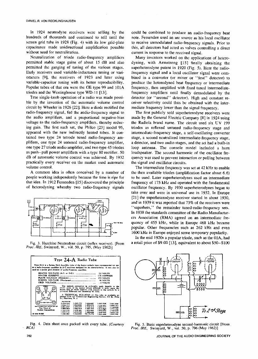
Neutralization of triode radio-frequency amplifiers Many inventors worked on the applications of hetero-permitted stable stage gains of about 15 dB and also dyning, with Armstrong [15] finally obtaining thepermitted the ganging of tuning of the various stages, superheterodyne patent in 1920 (Fig. 5). Here the radio-Early receivers used variable-inductance tuning or vail- frequency signal and a local oscillator signal were com-ometers [9], the receivers of 1923 and later using bined in a converter (or mixer or "first" detector) to
variable-capacitor tuning with its better reproducibility, produce the heterodyned beat frequency or intermediatePopular tubes of that era were the GE type 99 and 10lA frequency, then amplified with fixed tuned intermediate-
triodes and the Westinghouse type WD-11 [13]. frequency amplifiers until finally demodulated by theTrue single-knob operation of a radio was made pass·- detector (or "second" detector). High and constant re-
hie by the invention of the automatic volume control ce·var selectivity could thus be obtained with the inter-
circuit by Wheeler in 1926 [22]. Here a diode rectified the mediate frequency lower than the signal frequency.radio-frequency signal, fed the audio-frequency signal to The first publicly sold superheterodyne receivers were
the audio amplifiers, and a proportional negative-bias made by the General Electric Company [8] in 1924 usingvoltage to the radio-frequency amplifiers, thereby reduc- the Radiola brand name. The circuit used six UV 199
ing gain. The first such set, the Philco [23] model 95, triodes as reflexed untuned radio-frequency stage and
appeared with the new indirectly heated tubes. It con- intermediate-frequency stage, a self-oscillating convertertained two type 24 tetrode tuned radio-frequency am- stage, a second neutralized intermediate-frequency stage,planers, one type 24 untuned radio-frequency amplifier, a detector, and two audio stages, and the set had a built-inone type 27 triode audio amplifier, and two type 45 triodes loop antenna. The console model included a hamas push-pull power amplifiers with a type 80 rectifier. 50 loudspeaker. The second harmonic of the oscillator fre-
dB of automatic volume control was achieved. By 1932 quency was used to prevent interaction or pulling betweenpractically every receiver on the market used automatic the signal and oscillator circuits.
volumecontrol. Theintermediatefrequencywas setat 42 kHzto enableA common idea is often conceived by a number of the then available triodes (amplification factor about 6.6)
people working independently because the time is ripe for to be used. Later superheterodynes used an intermediatethat idea. In 1912 Fessenden [15] discovered the principle frequency of 175 kHz and operated with the fundamental
of heterodyning whereby two radio-frequency signals oscillator frequency. By 1930 superheterodynes began totake over and were in universal use in 1932. In Europe[21] the superheterodyne receiver started in about 1930,
L "_ and in 1939 it was reported that 73% of the receivers were
_0__. -o_o,-_......... _ "superhets," the remainder tuned-radio-frequency sets.
I,?_ _,.,[ _-;7_o ....i_o_ _ ____ In 1938 the standards committee of the Radio Manufactur-
....... il °" ers Association(RMA) agreedon an intermediatefre-quency of 455 kHz, while in Europe 468 kHz became
"0"°'0']- popular. Other frequencies such as 262 kHz and even] 1 t _--_ -&---_f' .... 1600kHz in Europe enjoyed some temporary populailty.
In the mid 1920s a popular triode, such as the 0lA, had
Fig. 3. Hazeltine Neutrodyne circuit (reflex receiver). [From a retail price of $9.00 [13], equivalent to about $50-$100Proc. IRE, Swinyard, W., vol. 50, p. 795, (May 1962)]
Type 24.A Radio Tube __. (_7 / }-i''_v_v[_-`,_.''_._'_
_2,.,l..S ....G*idAmpl,h..,.beo,,S.........hod..................... _f _VIlu · rmdio-frequenc_ ··planer in A-C ·civets de*lined for its characteristic;. It may ·Ilo he _ % I
and u · ·green Irid detector or audio-frequency mmpi·her. _ '.HEATER VOLTAGE (A.C or D,C.) ........................................ 2.5 VOLTS
HEATER CURRIgNT ............................................................ 1.75 AMPERES _1 )_.PLATE VOLTAGE (Mix mum) ...................................... 275 VOLTSSCREEN VOLTAGE (Maximum) ........................................... 90 VOLTS
GRID VOLTAGE .................................................................... 3 VOLTS _ ,_The cathode connection il prelei*ably made directly to the I . _ ,.
center point of the heater circuit although in tome cue· the
_o_w _(_ _ ......... be made ne, ...... ·th ......... he .rode by ipotential difference not exceed·al 45 volts. T _"
request from our Commercial EnSin_rlnh Section, 415 So. FittbSt.. Harrison. N. J.
PATSNTSi .2og.sle4 t .saa._Te i._l. ae? i .saT.7oa 1.el_s.ao9I._.217 1,3s4.mae 1.4se,s2a t ._s9.437 1.eme.lo3
Top View o! 1.Jl80,394 I,aas.8?_ t,,mo.alo l.els,e_ I.?an.aeoSooket Connectionl 1.303.579 1,410, 40g 1,492.0c_) 1.ezra t.74s.02e1,307,_10 1.4i0.550 t .4o0.0o8 i ,e_.058 1.81R, io 3
11 AdA (11-1110 1.39m,283 1.421.055 VIE-15,278 l,$OI.dde I.es_.eae
Fig. 4. Data sheet once packed with every tube. (Courtesy Fig. 5. Basic superheterodyne second-harmonic circuit [FromRCA) Proc. IRE, Swinyard, W., vol. 50, p. 796 (May 1962)]
762 JOURNALOFTHEAUDIOENGINEERINGSOCIETY

HOME MUSIC REPRODUCING EQUIPMENT
at today's prices. All sorts of ingenious tricks were a 1-watt .amplifier. At a price of $250 this model alsodevised to minimize tube count, while maximizing per- provided power for the Radiola 28 superheterodyne re-formance, ceiver,whichbecamethe firstbatterylessradioreceiver.
The most popular trick of minimizing tube count in Prior to the early 1920s power amplifiers were probablyradio receivers of the 1920s was "reflexing." It is not quite small because Rice and Kellogg first had to buildknown who discovered that a tube could amplify signals their own amplifier in order to test the concept of their
not only in one frequency range but in several frequency loudspeaker. In 1923 Green and Maxfield [26] describedranges simultaneously. Consequently many receivers, par- public address systems, and in 1924 Martin and Fletcherticularly neutrodyne receivers, were designed in which the [27] described high-quality transmission and reproductionsame tube acted both as a radio-frequency amplifier and as of speech and music.an audio amplifier. The earliest superheterodynes also The state-of-the-art commercial power amplifiers ofmade use of reflexing as shown above. 1926 were the Western Electric [28] amplifiers employing
Unfortunately all reflex receivers [24] had the common directly heated 205-D triode tubes, operating single-endedfailing of interaction (later known as intermodulation) and in push-pull and delivering 2.5 and 10 watts,between the two signals because of tube nonlinearity. This respectively. These amplifiers were used successfully intoresulted in such side effects as the inability to tune the the 1930s in movie theaters for sound reproduction ofvolume to zero, even though no more desired audio- talking pictures, generally in conjunction with highlyfrequency signal passed through the stage, efficient horn loudspeakers of "theater-size" dimensions.
Reflex circuits disappeared as soon as tubes became less The desire to be able to play music louder than wasexpensive than the additional circuit complexity entailed, possible before led to a type of competition which took itsapproximately in the early 1930s in the United States and name from the automobile trade, the "horsepower race."in the mid-1930s in Europe. A powerful receiver of 1925, using the new "low-mu"
During the years around 1920 another circuit appeared triodes and a B battery eliminator generally had less thanwhich today has an important influence on all reproduction ½ watt output [13]. While the 1926 Radiola model 104of music. Previously when attempting to boost power, was capable of 1 watt output, a typical 1929 "high-output tubes in parallel would be used. Later it was performance" set used the new oxide filament low-mudiscovered that a larger power increase could also be power triode type 45 capable of 1 to 3 watts (single-endedobtained with two tubes operating in push-pull, that is, or push-pull) to the loudspeakers. Contributing to thiswhen one tube had an increasing signal, the other had a increased output was the advent of indirectly heated tubes,decreasing signal, causing one of the plate circuits to such as the type 27 triode and the type 24 screen grid tube,"push" current into the load while the other tube pro- which permitted a receiver to be operated directly of theceeded to "pull." Since driving signals of opposite phase one power line without hum introduced in the cathodewere required to result in an output signal of opposite circuit, the oxide-coated tubular metal cathode enclosingphase, both input or driving transformers and output the heater and shielding the tube elements from its humtransformerswererequired, field.
Beginning in the 1930s driving transformers were The search for higher power prior to 1930 took twoeliminated with the advent of indirectly heated tubes, to basically different routes which later combined. In Europereoccur when high-power tube amplifiers were designed engineers at Philips [29] discovered that the high-currentand again when transistors were used in audio circuits low-voltage knee of the zero-grid bias curve of a tetrode oraround 1960. Not until complementary NPN and PNP pentode permitted a larger audio power output to betransistors became available did both output and input obtained from such a tube than that available from a triode
transformers become obsolete in home audio equipment, optimized for the same heater. This led to the developmentPush-pull circuits not only had lower distortion than of pentode power tubes (with an oxide coated filament)
"single-ended" circuits (even harmonics generated in the which appeared first around 1930.output stage tend to cancel), but also output transformers In the United States Barton [30] described the class-Bdid not suffer from saturation problems by the direct idling amplifier in 193 I. A class-A amplifier is one in which thecurrent, thereby extending low-frequency response, output tube (or other device) conducts throughout theFurthermore, the circuit had low sensitivity to power- signal input cycle. In a class-B amplifier one tube con-supply hum. It is now the universal output circuit, ducts for one half-cycle while the other conducts for the
The first attempted "loudspeaking" radio resulted in other half.horns attached to telephone receivers [8]. This soon Barton's class-B circuit permitted the power of am-proved to be unsatisfactory. The moving-armature plifiers to be increased beyond what was consideredloudspeaker was the next popular reproducer. Balanced- possible by the mere addition of a power output tube. Aarmature receivers, because of their simplicity of construc- further power increase caused by increased peak platetion, survived in the United States until the 1930s and in currents was made possible by increasing the grid voltageEurope until about 1940 in a German two-tube receiver, drive to positive instantaneous voltages, while maintain-the DKEmodel, ing the output tubebias voltage, the C-battery,at a fixed
In 1925 Rice and Kellogg [25] of the General Electric voltage rather than that determined by cathode resistorCompany described the moving-coil loudspeaker with first voltage drop. Up to that time the use of a positive griduse in the Radiola model 104 in 1926, which also included signal was equivalent to entering a forbidden region. With
OCTOBER/NOVEMBER1977,VOLUME25,NUMBER10/11 763
DANIEL R. VON RECKLINGHAUSEN
tube types then'available output powers approaching more The engineer's life was made a little easier whenthan 10 watts were soon achieved, the driver amplifiers Sawyer [34] in 1931 described the bimorph Rochelle saltproviding the peak grid current, transducer, which became known as the crystal pickup.
In 1935 both paths converged as the indirectly heated These pickups, first produced by the Brush Developmentbeam-power tetrode [31] became available. Performing Company, were comparatively light in weight, requiringlike a pentode, but with greater available low-voltage only 1 or 2 ounces of tracking force, had an availablecurrent, this tube, the 6L6, was originally manufactured '"permanent" stylus, and produced an output of up to 2with a metal envelope. Later on it became available with volts when loaded by a grid leak resistor while havingvarious glass envelopes and capable of 6.5 watt power constant-amplitude characteristics. This meant less gain
· output (single-ended) to 24 watts (class-AB push-pull, no and less equalization required than before, and the populargrid current with cathode bias) to 60 watts (class-AB low-cost connection was between the grid of the outputpush-pull with grid current). This tube became the tube and ground. Perhaps a million radios had such astandard high-power audio-amplifier tube used in designs "phono" jack connection, and an untold number ofrated between 20 and 50 watts appearing as late as the electric phonograph attachments contained such a pickup1960s. and a simple motor-driven turntable.
When electrically recorded phonograph records were Radios and radio-phonographs of the 1930s haddescribed by Maxfield and Harrison [32] in 1926, along magnetic loudspeakers only in the lowest models andwith their improved acoustic reproducer, the electric pho- electrodynamic loudspeakers in almost all others. Thenograph pickup had already been invented. The Western Radio industry [8],. having converted from battery-Electric 4A pickup [28] was used for the reproduction of the operated receivers to B battery eliminators (Philadelphiatalking picture sound recorded on 16-inch 33_?3-r/min Storage Battery Company, 1924), to A battery eliminatorsrecords according to the Vitaphone method first demon- (same company soon thereafter), to the radio with integralstrated publicly in early 1927. A and B eliminators (Zenith, 1926), to ac filament tubes
The improved acoustic phonograph, the Orthophonic (1926), also converted to power-line operation of theVictrola [5] of 1926, only one year later had an all-electric loudspeaker. The magnetic field of the typical elec-phonograph rival, the Brunswick Panatrope, produced by trodynamic loudspeaker was a wound coil, a choke, whichthe Brunswick-Balke-Collender Company aided by en- could be used to filter the rectified high voltage (or B+gineers from RCA, General Electric, and Westinghouse. voltage) required by the circuit.Soon other all-electric phonographs and radio- It worked, but the loudspeaker emitted a hummingphonograph combinations appeared, with the effect that 'sound caused by imperfect filtering. Pridham [35] ofthe .acoustic phonograph..was 'virtually displaced in the Magnavox invented the hum-bucking coil in 1929 whichunited States in 1.930 by the all:electric radio- consisted of a few turns of wire wound beside the field coilphonograph combinations. Acoustic phonographs con- and connected in series with the voice coil in such atinuedto be produced for ten more years .in Europe and as fashion to minimize hum.portable instruments Worldwide. Since filter capacitors were expensive, often unreliable,'.The electric phonograph pickup of the years starting, and as electrolytic capacitors with a liquid electrolyte
with about 1927 was the magnetic pickup, which had a' ' often sensitive to orientation, marginal power supplybalanced armature using a horseshoe magnet. The output filtering was the rule rather than the exception of thewas a good fraction of I volt, and the upper frequency 1930s. Other ingenious hum-reducing tricks were used.limited by a resonance was between 2_hand 4 kHz. Using They included partial filtering of hum in the grid circuit,replaceable "needles," the tracking force was several adjusted in such amplitude and phase to cancel hum in theounces, platecircuit(Rechnitzer[36]of Telefunken,1928),or the
The connection of such pickups to the radio circuits of use of tapped filter chokes (McLennan [37], Internationalthe 1920s and 1930s was governed principally by the General Electric, 1931), or the adjustment of the operatingdesire to obtain enough amplification, since the output voltages of one tube in a push-pull circuit to minimizefrom a pickup was less than that of a high-level detector, hum. Hum in earlier lo TM current stages was oftenLittle effort was made to properly equalize a pickup adequately suppressed by additional filtering.response, since each recording company had its own, The beginning uses of light-weight magnetic pickupsoften secret, recording curve, each manufacturer striving (General Electric [38], 1948) focused on another source offor its own distinctive sound. The radio-phonograph hum--leakage current from the heater to the cathode andengineers had to make the best of such a situation, which hum_coupling from the filament into the cathode and gridwas complicated by the fact that economic considerations circuits. The solution was to use the cathode type tubesdid not permit an additional phono preamplifier tube for .with a filtered direct-current filament supply. Scott [39]
the receiver and switches were often unreliable. One of the (model 210 A, 1947) used two 12.6-volt 150-mA pream-common solutions was to use one of the intermediate plifier tubes with filaments connected in series as the
frequency amplifier tubes as a preamplifier [33] for the cathode resistor of the 6L6 push-pull power amplifier.pickup, choosing the values of the high-frequency bypass Not until transistors and integrated circuits permitted smallcomponents so as to provide for some equalization. This assemblies, have equivalent input hum levels reached anyalso simplified the switching to a simple disabling of significantly lower value.amplification ahead of that stage. Volume controls, or high-impedance potentiometers
764 JOURNALOFTHEAUDIOENGINEERINGSOCIETY
HOME MUSIC REPRODUCING EQUIPMENT
made from pressed graphite or carbon, became available larger boost with further advance of control setting.in about 1925 and were used as volume controls in all Separate controls for bass and treble were provided, andpower-line operated radios manufactured, with the excep- these are still with us in essentially unchanged function.tion of regenerative sets. Long-distance telephone circuits, Originally most of these bass and treble controls wereas shown in a 1919 patent issued to T. B. Wier [40] of passive, the repeatability of frequency response dependentWestern Electric, used a volume control along with a filter upon the accuracy of attenuation of the potentiometer.which removed high-frequency noise. Others sought to have separate boost, flat, and attenuate
Tone controls are another matter: no clear record of networks and attempted touse the tone control as a faderachievement exists here. To this date, tone controls are a control between those networks [39]. Finally, P. J. Baxan-
boon or a bane, panacea or pandemonium. The compiler dall [43] developed the negative-feedback tone control in
of the Radiotron Designer s Handbook [24, pp. 635-678] 1952, a circuit which.combined a continuous bass controlwrites, "Tone control is a controversial subject with very with a continuous treble control having input, output, andstrong conflicting views held by many competent au- amplifier input terminals, and a common high-gain am-thorities." To this day these words are true; however, plifier connected between the amplifier input and outputmany forms of tone control fall under the general heading terminals of both controls. This circuit gained rapidof equalization or correction of frequency response of acceptance because of its simplicity and is in almostprogram material intentionally preequalized according to universal use today, providing unity gain in the "flatsome standard. For example, the equalizer circuits used to response" position, rather than an insertion loss requiredcompensate for the RIAA characteristic of records, or the to be larger than the maximum desired boost.NAB characteristic of certain tape recordings are not tone Radio and radio-phonograph designers of the latecontrols in the conventional sense, although they at one 1920s discovered that their sets sounded "thin" at lowtime fell into the ','controversial" category, volume. Jacobs [44] in 1930 applied for a patent for a
However, the user-adjustable controls affecting tone volume control in which the bass frequencies are at-quality are contested. For the purist no tone controls are tenuated less than high frequencies at low control settings.desirable, "flat response" is the ideal. '_ His loudness control, or compensated volume control, is
Historically, tone controls started as low-pass filters, still with us today.usually switched as a passive filter (that is,:not containing Any broadcast or recording medium always suffers fromamplifiers) designed to remove high-fr_q_'_ncy noise; the combination of finite bandwidth and finite signal-to-similarly bass boost filters are really a._i_iSie R-C low- noise ratio. Improved broadcasting or recording mediapass filter having finite, limited attenfi[ti'0n: :at high fre- show improved numbers, but the same types of limits stillquencies. Such switch type controls :W_i'e-described by exist. A large number of schemes have been invented overScroggie [41] in 1932. The result was_that radio consoles the years to make the ear believe that the received or[24] of the 1930s all the way into the 1960s had a series of reproduced signal is improved over the unprocessed ver-switches which controlled tone quality. Such a "_luality sion. One of the most successful is preemphasis, whereswitch" usually varied in complexity in proportion to the certain frequencies are boosted in transmission and thenquality level of the set.iA series of interlocked push-button attenuated along with noise upon reproduction.switches that might also vary the selectivity Of the set were Ever since the advent of broadcasting and recording, the
'"azz"often labeled poetically "orchestra," j , "alto," engineers have attempted to make maximum use of the"tenor," "distant," and many other titles. There was medium. Adjusting modulation level or "riding gain" is aoften justified suspicion that none of the switch positions standard method. The compressor for records dates backin certain sets resulted in flat response. Starting in the late to 1927 when Mitchell [45] (Columbia Records) varied1930s certain of these switch positions changed the sensitivity of the electrodynamic record cutter with afrequency response by changing resistor-capacitor net- rectified audio signal.works in the feedback loop of the power output stage. The expander, at the other end of the music reproduc-
One early pioneer in tone control circuitry is Aceves tion chain, dates back to 1931 when Cook [46] (United[42] who in 1930 and 1931 applied for patents granted in Research Corporation) invented the volume expander,1934 using inductors and capacitors as tone control in consisting of variable-gain tubes receiving a rectified and
conjunction with an amplifier, filtered gain control signal in proportion to the inputContinuous tone controls appeared first in the late signal. Thus loud music passages could be reproduced
1930s, mostly as a high-frequency RC filter. This control even louder.is still with us as a "tone" control in simple radios or tape The problems of compression and expansion are still
or record players and is generally "flat" in its extreme with us today. First, if the two are not matched, unnaturalposition. A variation of it is a tone control which at- reproduction can exist. In particular, reference levels havetenuates bass in one extreme position ("speech"), treble to be maintained carefully. Second, since compressorsin the other extreme, and has relatively flat response in the and expanders obtain their control signal from a rectifiedmiddle ("music"). and filteredprogramsignal,there is a delaybetweencause
In the years following World War II, a number of tone and effect. For example, a compressor may show tempor-control circuits appeared which were able to attenuate the ary overshoot of output, and an expander may showresponse progressively less as the control was advanced, periods of high gain with high noise reproduction after ahad a flat response position, and then a progressively program peak has passed. Swishing noises and thumping
OCTOBER/NOVEMBER 1977, VOLUME 25, NUMBER 10/11 765
DANIEL R. VON RECKLINGHAUSEN
noisesmay be heard. Thismay be thecause of publishedargumentsin the tradeEtzrodt [47] (Siemens and Halske) proposed in 1932 press until the late 1950s about the sound of triode
that the control signal of a compressor for use by a amplifiers and pentode amplifiers. The difference 'in in-matching expander be transmitted along with the com- temal impedance and distortion between designs usingpressed program material, moderate amounts of feedback can account for the argued
Other complete closed-loop schemes involve the split- differences. However, these arguments have now beenting of the audio-frequency bands into multiple frequency settled, or rather overshadowed, by arguments over tuberanges, compression and expansion after transmittal and sound and transistor sound. Today arguments about distor-then recombination, as invented by Hammond [48] in tion, its nature, definition, audibility, and measurement1931. Barney [49] (Bell Telephone Laboratories)propos- persist. From some of the arguments advanced, thised a two-frequency-band scheme in. 1942. The most subject will not be resolved soon.
successful of these schemes is still with us today, the Feedback amplifiers for music reproduction becamefrequency selective compressor-expander scheme by available soon after World War II [39]. Prior to this,
Dolby [50] (1965). Here multiple-frequency-range corn- adjustments to amplifiers were made only after an exhaus-pression and expansion using the diode voltage-current tive graphical analysis of published tube characteristicslaw as basis over a limited volume range in multiple- [57]. Distortion-measuring equipment during that timefrequency ranges have proven successful in many record- consisted of wave analyzers (or selective voltmeters)ings and broadcasts, which had to be tuned to each harmonic. State-of-the-art
All the automatic noise-reducing schemes referred to oscillators produced less than 1-percent distortion.above are closed systems, that is, the program material is The situation changes rapidly thereafter. In 1949 McIn-processed prior and after recording or transmission. Other tosh and Gow [58] described a new 50-watt amplifierschemes tried to obtain the most "listenable" signal from which had a then unheard-of guarantee of less than 1%whatever the programmight be. distortion at full power over the entire audio range
In 1930 W. Van B. Roberts [51] (RCA) applied the between 20 and 20 000 Hz, and less than _/_%distortion at
automatic volume control bias voltage to a one-tube audio midfrequencies. This performance was accomplishedamplifier stage. The tube's grid-plate capacitance reduced using a bifilar wound driver transformer and a bifilarfrequency response for weak signals (or no AVC) and wound output transformer in a common feedback loop.permitted a wider range for stronger signals. This model cost nearly $300 with amplifier and power
After many other futile tries by others, H. H. Scott [52] supply on separate chassis and set a new standard forintroduced his dynamic noise suppressor in 1946. Scott high-fidelity music reproduction.realized that the effective bandwidth of the human ear The tape recorder, the Magnetophon, which wasvaries with reproduced signal level, and that a lesser brought to the United States from Germany as one of thebandwidth is acceptable for low-volume signals. Reduc- spoils of war, was used in the transcribed Bing Crosbytion of bandwidth at low and high frequencies was sensed broadcasts of 1946. The popular tape recorder, the Brushby the absence of program material in the high bass and "Soundmirror," used black iron oxide paperbacked typelow treble regions, respectively, and effected by reactance 100 tape by the Minnesota Mining and Manufacturingtubes. Scott's Dynaural noise suppressor was successful Company, soon to be followed by "acetate" plastic tapeuntil the beginning of stereophonic records in 1957 and with a red iron oxide, type 110. In 1947 General Electricwas used to process many 78-r/min in master recordings released the variable-reluctance pickup [59] with an avail-into long-playing records. Burwen's [53] noise-reducing able accessory preamplifier, containing one 6SC7 high-musystem, adjusted to wide-dynamic-range program material dual triode. In 1948 Columbia Records [60] introduced
as available today, has been able to remove the swishing long-playing records, followed in 1949 by RCA's 45-r/problems of earlier systems by nonlinear processing, min record [61].
Circuit theory 'advanced over the years. Although In 1949 it was also possible to make stereophonic tapeOhm's law dates back to 1827 and Kirchoff's laws to recordings by using two half-channel recording heads1845, complex quantities in electrical engineering were "staggered" by mounting space normally required by theonly vulgarized by Steinmetz in 1894. full-track recording and playback heads [65].
Prior to 1932 it was thought by all scientiests that no The consumer electronics industry tried valiantly to
more than 6 dB feedback could be applied to any device keep pace with all these new developments. In 1935 the[54]. They reasoned that negative feedback behaved ac-dc radio had been the latest development, and in 1939,
similar to positive feedback, where any more than 6 dB 1.4-volt miniature tubes permitted portable battery-caused oscillation. In 1932 Nyquist proved his stability operated sets which led to the 1946 Belmont pocket radiocriterion, which was experimentally confirmed by Peter- [8].son in 1934. The advantages of negative feedback were In the late 1940s the music lover could choose from
systemically discussed by Black [55] in 1934, and the several makes of equipment, the electronics built on arelations of amplitude and phase were clarified by Bode in chassis with tubes and capacitors and transformers stick-
1940. Not until about. 1945 were most of the fundamental ing up and the controls out front behind a spaced flatfeedback concepts made known [56]. panel. When desired, it could be insialled into a piece of
It is, therefore, not surprising that most electronic furniture by doing cabinet work. Loudspeakers came asequipment prior to 1945 contained little or no feedback, bare "chassis" or in a cabinet styled for "professional"
766 JOURNALOFTHEAUDIOENGINEERINGSOCIETY

HOMEMUSICREPRODUCINGEQUIPMENT
use. Interconnections were left to the user's dexterity, vertised their products. Federated Semiconductor Com-
Separate power supplies for the field windings of elec- pany (sales agents for Germanium Products Corporation),trodynamic loudspeakers were no longer required, the Transistor Products, RCA, and Raytheon advertised prod-high-flux Alnico permanent magnet systems took the place ucts, the latter company achieving fame with the CK 721of electromagnets, and CK 722 germanium junction transistors introduced a
In the late 1940s loudspeakers for home music repro- few months later. These types were used by many an engi-duction were relatively efficient, and the average separate neet who wanted to learn about these new devices.amplifier had an output of 10 watts. Toward the end of the The same issue also had a theoretical paper by Shockley
1950s the benefit of wider and smoother frequency re- describing "a unipolar field-effect transistor," a devicesponse of the "low-efficiency" bookshelf loudspeaker that was yet to be made.was compensated by an increase in amplifier power to an The first consumer application of transistors was in
average of perhaps 20 watts. In the 1950s stereo records heating-aid amplifiers, which up to the early 1950s con-and stereophonic broadcasting necessitated two channels, tained usually three subminiature vacuum tubes as am-each averaging perhaps 20 watt output, or a total of 40 plifiers.watts. Today, to reproduce higher peak sound levels In 1954 Regency marketed the first transistorized radio.seems to indicate an average of 4 × 20 watts or 2 × 40 The 1957 Radio Shack catalog [65] lists DeWald, Halli-watts, or 80 watts. Already, amplifiers of several hundred crafters, Regency, and "Famous Make" transistor radioswatts per channelexist, at about three times the price of ac-dc tube radios.
Statistically, a power output increase of about 3 dB per The same catalog also shows the first transistorizeddecade cannot continue at this pace. The consequences of high-fidelity product, a three-transistor preamplifier forhome-type amplifiers by the turn of the century having microphone or magnetic pickup produced by the Fisheroutput power ratings in the kilowatt per channel range Radio Corporation.provide quite a stimulus to a fertile imagination. The first transistor high-fidelity amplifiers were pro-
Amplifier quality has also improved over the years. If duced in 1961 by Transistronics [66], the model TEC Stotal harmonic distortion over the total audio frequency 15. A matching tuner, model TEC 15 MPx, was alsorange is used as one measure, halving of distortion every offered. In the following years a number of companiesdecade seems to have occurred with the average now offered transistorized music reproduction equipment.around 1/2percent. The use of more rugged transistors helped the engineers
The improvements in phonograph pickups, resulting in to design more reliable equipment. The author was at thatwider frequency response and lower tracking force, have time successful in analyzing the demands on performancealso resulted in lower output voltages. If reference record- of output transistors and devising circuits which woulding levels of 3.5 cm/s per channel at 1000 Hz or 5 cnds provide protection against excessive dissipation [67].lateral modulation are used as a "medium loud" signal, Since that time, protection of amplifiers by electronicthe pickup output levels have decreased at an irregular rate means other than fuses has become standard for allof 3 to 6 dB per decade. As a result, the gain of amplifiers high-power transistor circuits.measured between the phono input and the loudspeaker In 1959 Kilby [68] of Texas Instruments described aoutput has increased by more than 6 dB per decade. Iris to solid-state circuit in which all elements (transistors,the credit of the amplifier designers that the signal-to-noise diodes, resistors, and capacitors) were made by standardratio has not been degraded but has actually improved, semiconductor processes. This first integrated circuit be-
Fortunately there were several major developments came the forerunner of all the integrated circuits used bywhich made all this possible. Electronic engineers in the the millions in computers, calculators, and many othertube era were often frustrated by the singularity of the applications. Soon thereafter Noyce [69] of Fairchildtube--electron flow is always from the cathode to the Semiconductor developed the planar semiconductor pro-other elements--they wanted a device with current flow cess which permitted isolated function of these parts.in the opposite direction to be able to devise a better Originally devised as a means to decrease space require-push-pull circuit or a better direct coupled circuit, ments, to increase reliability by eliminating human error,
Although few realized it at the time, the solution was and decrease manufacturing costs (all achieved), thedescribed in 1948 by Bardeen and Brattain [63] of Bell integrated circuit manufacturers also achieved devices
Telephone Laboratories. The germanium point contact which were closely matched to each other. Because of thistransistor of 1950 was a fragile device, prone to oscillate, matching and more particularly from understanding the
yet it amplified and did not require heater power. Just nature of semiconductor behavior, linear integrated cir-three years after the original announcement, Shockley's cuits became possible. Widlar [70] of Fairchild Semicon-work on the theoretical aspects of p-n junctions resulted in ductor in 1965 succeeded in devising the /aA709 opera-the development of the (germanium) junction transistor in tional amplifier, an integrated circuit which has spawned1951 by Shockley [64] and his coworkers at Bell Tele- all operational amplifiers used today, from instrumenta-phone Laboratories. tion to musicreproduction. Of the latter, the firstcommer-
Soon other manufacturers produced transistors for cial use of operational amplifiers as equalized pream-commercial use. In November of 1952 the Proceedings of plifiers by Scott in 1969 resulted in reduced noise and
Institute Of Radio Engineers was a special issue on improved circuit stability.transistors. The then current transistor manufacturers ad- During the 1930s the Loewe Company [71] in Germany
OCTOBER/NOVEMBER1977,VOLUME25,NUMBER10/11 767
DANIEL R.VON RECKLINGHAUSEN
offered a series of radios which contained an early form of ferring signals. The model 310A Scott [73] tuner was theintegrated circuit, two or three vacuum tube sections along first FM tuner making use of these requirements.with resistors, and capacitors inside a common evacuated In 1953 Armstrong [20] demonstrated before the FCC a
glass envelope, systemofFM broadcastingwhichpermittedtwoindepend-The successful transistorized designs had both signal ent programs to be broadcast by the same FM station
source and load under complete control of the designer, without mutual interference. The second program, mod-The first transistorized record playing system, the KLH ulated on a subcarrier (which in turn modulates the FM
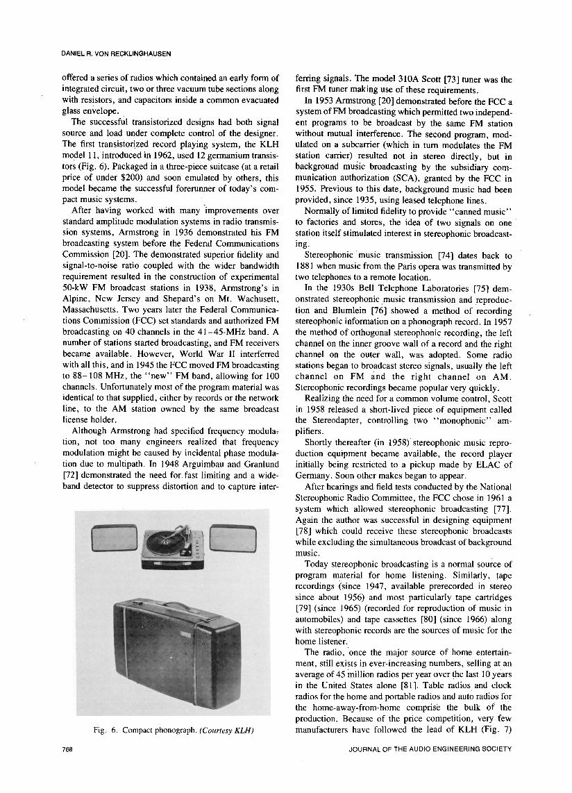
model 11, introduced in 1962, used 12 germanium transis- station carrier) resulted not in stereo directly, but intors (Fig. 6). Packaged in a three-piece suitcase (at a retail background music broadcasting by the subsidiary corn-price of under $200) and soon emulated by others, this munication authorization (SCA), granted by the FCC inmodel became the successful forerunner of today's com- 1955. Previous to this date, background music had beenpact music systems, provided, since 1935, using leased telephone lines.
After having worked with many -improvements over Normally of limited fidelity to provide "canned music"standard amplitude modulation systems in radio transmis- to factories and stores, the idea of two signals on onesion systems, Armstrong in 1936 demonstrated his FM station itself stimulated interest in stereophonic broadcast-broadcasting system before the Federal Communications ing.
Commission [20]. The demonstrated superior fidelity and Stereophonic music transmission· [74] dates back tosignal-to-noise ratio coupled with the wider bandwidth 1881 when music from the Paris opera was transmitted byrequirement resulted in the construction of experimental two telephones to a remote location.
50-kW FM broadcast stations in 1938, Armstrong's in In the 1930s Bell Telephone Laboratories [75] dem-Alpine, New Jersey· and Shepard's on Mt. Wachusett, onstrated stereophonic music transmission and reproduc-Massachusetts. Two years later the Federal Communica- tion and Blumlein [76] showed a method of recordingtions Commission (FCC) set standards and authorized FM stereophonic information on a phonograph record. In 1957broadcasting on 40 channels in the 41-45-MHz band. A the method of orthogonal stereophonic recording, the leftnumber of stations started broadcasting, and FM receivers channel on the inner groove wall of a record and the rightbecame available. However, World War II interferred channel on the outer wall, was adopted. Some radiowith all this, and in 1945 the FCC moved FM broadcasting stations began to broadcast stereo signals, usually the leftto 88-108 MHz, the "new" FM band, allowing for 100 channel on FM and the right channel on AM.channels. Unfortunately most of the program material was Stereophonic recordings became popular very quickly.identical to that supplied, either by records or the network Realizing the need for a common volume control, Scottline, to the AM station owned by the same broadcast in 1958 released a short-lived piece of equipment calledlicenseholder, the Stereodapter,controlling two "monophonic" am-
Although Armstrong had specified frequency modula: plifiers.
tion, not too many engineers realized that frequency Shortly thereafter (in 1958)·stereophonic music repro-modulation might be caused by incidental phase modula- duction equipment became available, the record playertion due to multipath. In 1948 Arguimbau and Granlund initially being restricted to a pickup made by ELAC of[72] demonstrated the need for fast limiting and a wide- Germany. Soon other makes began to appear.band detector to suppress distortion and to capture inter- After hearings and field tests conducted by the National
Stereophonic Radio Committee, the FCC chose in 1961 a
.. systemwhichallowedstereophonicbroadcasting[77].Again the author was successful in designing equipment[78] which could receive these stereophonic broadcastswhile excluding the simultaneous broadcast of backgroundmusic.
Today stereophonic broadcasting is a normal source ofprogram material for home listening. Similarly, taperecordings (since 1947, available prerecorded in stereosince about 1956) and most particularly tape cartridges[79] (since 1965) (recorded for reproduction of music inautomobiles) and tape cassettes [80] (since 1966) alongwith stereophonic records are the sources of music for thehome listener.
The radio, 'once the major source of home entertain-ment, still exists in ever-increasing numbers, Selling at anaverage of 45 million radios per year over the last 10 yearsin the United States alone [81]. Table radios and clock
radios for the home and portable radios and auto radios for'the home-away-from-home comprise the bulk of theproduction. Because of the price 'competition, very few
Fig. 6. Compact phonograph. (CourtesyKLH) manufacturers have followed the lead of KLH (Fig. 7)
768 JOURNALOFTHEAUDIOENGINEERINGSOCIETY

HOME MUSIC REPRODUCING EQUIPMENT
who in 1960 introduced a table model radio (model 8) very large number of channels have resulted in less thanwhich was capable of flat acoustic frequency response of perfect sound. The use of headphones has largely removedall but the bottom octave of FM broadcast limits, the sound transmission problem, but has introduced new
Radio-phonograph consoles, once the prestige music problems, the restriction of movement of the wearer ofreproducers in the home, have been declining in the recent headphones, his discomfort, and the lack of feedback onfew years, giving way to high-fidelity components, which the acoustic image while the listener moves his head. Thehave been rising in popularity ever since their introduction first two problems seem to be problems which may bein the years following World War II. resolved. The latter is a problem for the future: how to
Home music reproduction has had the benefit of the have two recorded channels of program material for thealmost regular introduction of a new service or a new two ears and how to present them to the mobile listener,convenience. In the last 30 years came the magnetic tape presenting him a stationary music image, predeterminedrecorder, the long-playing record, the "component" am- by the record. The listener will then be the determiningplifier, the high-quality tuner, background music via FM, part of the feedback loop. Furthermore, how will multipleprerecorded tapes, stereophonic records, stereophonic listeners be accommodated, perhaps without headphones?broadcasting, the automobile tape cartridge, and the tape Also, how can multiple program desires be handledcassette, without interferenceto each other? Here loudspeakers
The introduction in 1970 of four-channel sound is still with nearby electronically controlled sound absorptionin the undecided stage because several incompatible sys- may provide the answer.rems exist. There are systems which mix four channels All of these ideas, when in the process of development,into two channels for recording and broadcasting, the will result in new challenges which then may be over-original material in part recoverable by a mixing and come.automatic fading technique. There are systems which aretwo-channel and where stereophonic material is enhancedby additional delays and reverberation. Then there aresystems which transmit and record four channels using L-subsidiary modulation techniques. Finally, there are sys-tems of using multiple tape tracks. Some additionalsystems have been proposed for FM broadcasting. 2
At this time the solution is not clear, and sales offour-channel equipment and recordings have been a disap-pointment to many. The quadraphonic broadcasting pro-posals have been analyzed and tested and are now in the
hands of the FCC for further testing and possible decision. Fig. 7. Compact radio. (CourtesyKLH)Not until there is an easily available source of low-costprogram material to the average nontechnical consumerwill four-channel sound become popular. REFERENCES
Before this happens, there is another service which [1] "Edison's Pressure Relay," The Telegraphic J.,might entice the public: when stereophonic broadcasting vol. 5, pp. 149-150 (July 1, 1877).was proposed prior to 1960, there were several methods of [2] D. E. Hughes, "On the Action of Sonorous Vibra-FM broadcasting, other for TV broadcasting, and others tions in Varying the Force of an Electric Current," Proc.for AM broadcasting. Interest in AM stereophonic broad- Roy. Soc. (London), vol. 27, pp. 362-369 (1878).casting has reawakened, with committee meetings s cur- [3] H. E. Shreeve (W.E.Co.), U.S. Patents 791,655-6rently (March 1977) going on and field tests scheduled for (1905).midyear. Perhaps a new service will result from this effort. [4] T. Shaw, "The Conquest of Distance by Wire
Telephony," Bell Sys. Tech. J., vol. 23, pp. 337-421In the 100 years since the introduction of the phono- (Oct. 1944).
graph, the attempt has been to bring the stage or the [5] F. V. Hunt, Electroacoustics, Harvard Universityconcert hall into the home. Success has been remarkable, Press, Cambridge, MA, 1954.but not complete. Fidelity has been improved and multiple [6] O. Read and W. W. Welch, From Tin Foil tochannels were used for greater realism. The listening room Stereo, 2nd ed. Howard W. Sams & Co., (Indianapolis,always had its own contributing acoustics,not the least of IN, 1976), pp. 149, 158.which is the transmission of sound in both directions [7] R. A. Fessenden, "Recent Progress in Wireless
through walls and doors and windows. The resulting Telephony," Sci. American, vol. 96, pp. 68-69 (Jan. 19,restriction of the dynamic range, and the inability to use a 1907).
[8] W. O. Swinyard, "The Development of the Art ofRadio Receiving from the Early 1920's to the Present,"
2 The report to the Federal Communications Commission by Proc. IRE, pp. 793-798 (May 1962).the National Quadraphonic Radio Committee is available for a [9] J. T. Brothers, "Historical Development of Cum-fee from the Electronic Industries Association (EIA), ponent Parts Field," Proc. IRE, vol. 50, pp. 912-919 (MayWashington,DC20006. 1962).
a National AM Stereo Radio Committee, E. M. Tingley [10] J. A. Fleming, U.S. Patent 803,684 (1905).(EIA),Secretary. [11] L. DeForest,U.S. Patent879,532(1908).
OCTOBER/NOVEMBER 1977, VOLUME 25, NUMBER 10/11 769

DANIEL R. VON RECKLINGHAUSEN
[12] L. DeForest, "Discussion of E. H. Armstrong's [40] T. B. Wier, U.S. Patent 1,617,428 (1927).papers," Proc. IRE(Corr.), vol. 3, p. 239 (Sept. 1915). [41] M. G. Scroggie, "Amplifier Tone Control Cir-
[13] E. W. Herold, "The Impact of Receiving Tubes cuits," Wireless Eng., vol. 9, p. 3 (Jan. 1932).on Broadcast and TV Receivers," Proc. IRE, vol. 50, [42] J. G. Aceves, U.S. Patents, 1,984,357 andpp. 805-809(May1962). 1,984,450(1934).
[14] F. J. Mann, "Federal Telephone and Radio Cor- [43] P. J. Baxandall, "Negative Feedback Toneporation, A Historical Review 1909-1946," Elec. Com- Control-Independent Variation of Bass and Treble With-mun., vol. 23, pp. 377-405 (Dec. 1946). out Switches," Wireless World, vol. 58, p. 402 (Oct.
[15] C. Buff, "Radio Receivers--Past and Present," 1952).Proc. IRE, vol. 50, pp. 884-891 (May 1962): [44] C. T. Jacobs, U.S. Patent 1,938,256 (1933).
[16] L. A. Hazeltine, "Tuned Radio Frequency Am- [45] F. A. Mitchell, U.S. Patent 1,792,859 (1931).plification with Neutralization of Capacity Coupling," [46] E. D. Cook, U.S. Patent 1,928,410 (1933).Proc. Radio Club of Am., vol. 2 (March 1923). [47] K. Etzrodt, U.S. Patent 2,065,489 (1936).
[17] R. A. Heising, "Modulation Methods," Proc. [48] J. H. Hammond, Jr., U.S. Patent 2,008,825IRE, vol. 50, pp. 896-901 (May 1962). (1935).
[18] J. O. Weldon, "Transmitters," Proc. IRE, vol. [49] H. L. Barney, U.S. Patent 2,358,045 (1944).50, pp. 901-906(May 1962). [50] R. M. Dolby, Brit. Patent 1,120,541 (1968).
[19] R. F. Guy, "AM and FM Broadcasting," Proc. [51] W. Van B. Roberts, U.S. Patent Re 21,018IRE, vol. 50, pp. 811-817 (May 1962). (1939).
[20] "A Play-by-Play Retrospective," Broadcasting, [52] H. H. Scott, U.S. Patent 2,606,972 (1952).vol. 79, pp. 74-154 (Nov. 2, 1970). [53] R. S. Burwen, U.S. Patent 3,678,416 (1972).
[21] "Die Entwicklungsrichtung des Rundfunks," [54] V. Belevitch, "Summary of the History of CircuitRadio Amateur, vol. 19, pp. 149-150 (May 1942). Theory," Proc. IRE, vol. 50, pp. 848-855 (May 1962).
[22] H. A. Wheeler, "Automatic Volume Control for [55] H. S. Black. U.S. Patent 2,102,671.Radio Receiving Sets," Proc. IRE, vol. 16, pp. 30-39 [56] H. W. Bode, Network Analysis and Feedback(Jan. 1928). Amplifier Design (Van Nostrand, New York 1945).
[23] W. E. Holland and W. A. MacDonald, "The [57] F. Langforth-Smith, Radiotron Designers Hand-Philco '95' Screengrid Plus," Radio Broadcast, vol. 16, book, 3rd ed. (Wireless Press, Sidney, 1940). pp. 268-pp. 111-112(Dec.1929). 294.
[24] F. Langford-Smith, Radiotron Designer's Hand- [58] F. H. Mclntosh and G. J. Gow, "Description andbook, 4th ed. (Wireless Press, Sidney, 1953), pp. 1140- Analysis of a New 50 Watt Amplifier Circuit," Audio1146. Eng., vol. 33, p. 9 (Dec. 1949).
[25] C. W. Rice and E. W. Kellogg, "Notes on the [59] A. Douglas, "The G. E. Variable ReluctanceDevelopment of a New Type of Hornless Loudspeaker," Pickup," Electronic Eng., vol. 21, p. 21 (Jan. 1949).Trans. AIEE, vol. 44, pp. 461-475 (Apr. 1925). [60] P. C. Goldmark, R. Snepvangers, and W. S.
[26] I. W. Green and J. P. Maxfield, "Public Address Backman, "The Columbia Long-Playing MicrogrooveSystems," Trans. AIEE, vol. 43, p. 64 (1923) Recording System," Proc. IRE, vol. 37, pp. 923-927
[27] W. H. Martin and H. Fletcher, "High Quality (Aug. 1949).Transmission and Reproduction of Speech and Music," [61] B. R. Carson, A. D. Butt, and H. I. Reiskind, "ATrans. ALEE, vol. 43, p. 384 (1924). Record Changer and Record of Complementary Design,"
[28] J. K. Hilliard, "Movie Sound Reproduction," RCA Rev., vol. 10, pp. 173-190 (June 1949).Audio, vol. 61, pp. 44-60 (Mar. 1977). [62] M. Camras, "Stereophonic Magnetic Recorder,"
[29] G. Host and B. D. ,H. Tellegen, U.S. Patent Proc. IRE, vol. 37, pp. 442-447 (Apr. 1949).1,945,040(1934). [63] J. BardeenandW. H. Brattain,"The Transistor,a
[30] L. E. Barton, "High Audio Output from Rela- Semiconductor Triode," Phys. Rev., vol. 74, pp. 230-231tively Small Tubes," Proc. IRE, vol. 19, pp. 1131-1149 (July 15, 1948).(July1931). [64] W. Shockley,M. Sparks,andG. K. Teal, "P-N
[31] O. H. Schade, "Beam Power Tubes," Proc. IRE, Junction Transistors," Phys. Rev., vol. 83, pp. 151-162vol. 26, pp. 137-181(Feb. 1938). (July 1, 1951).
[32] J. P. Maxfield and H_ C. Harrison, "Methods of [65] Music in Your Home, Catalog 57-HF (RadioHigh Quality Recording and Reproducing of Music and Shack Corporation, Boston, 1956).Speech Based on Telephone Research," Bell Sys. Tech. [66] "Product Review Section, Amplifiers, Tuners,"J., vol. 5, pp. 493-523 (July 1926). Audio, vol. 45, pP. 36-49 (Aug. 1961).
[33] H. Pitsch, "Anschluss des Tonabnehmers," Aus- [67] D. R. yon Recklinghausen, U.S. Patent 3,668,545lese der Funktech., vol. 3, pp. 4-5 (Apr. 1941). (1972).
[34] C. B. Sawyer, "The Use of Rochelle Salt Crystals [68] J. S. Kilby, "Invention of the Integrated Circuit,"for Electrical Reproducers and Microphones," Proc. IRE, IEEE Trans. Electron Dev., vol. ED-23, pp. 648-654vol. 19, pp. 2020-2029(Nov. 1931). (July 1976).
[35] E. S. Pridham, U.S. Patent 1,901,331 (1933). [69] R. N. Noyce, U.S. Patent 2,981,877 (1961).[36] R. Rechnitzer, German Patent 603,008 (1928). [70] R. J. Widlar, "A Unique Circuit Design for a[37] M. A. McLennan, German Patent 642,384 High Performance Operational Amplifier Especially
(1931). Suited to Monolithic Construction," Proc. 1965 NEC, pp.[38] W. S. Bachman, U.S. Patent 2,511,633 (1950). 85-89.[39] H. H. Scott, "Dynamic Noise Suppressor," Elec- [71] P. H. Brans, RiOhren Vademecum 1945-1946.
tronics, vol. 20, p. 96 (Dec. 1947). (Regelien, Berlin, 1946), pp. 128-185.
770 JOURNAL OF THE AUDIO ENGINEERING SOCIETY
HOMEMUSICREPRODUCINGEQUIPMENT
[72] L. B. Arguimbau and J. Granlund, "Frequency ing Stations to Transmit Stereophonic Programs on aModulation Transmission Under Multipath Conditions," Multiplex Basis," Docket No. 13506, Federal Communi-Rep 42, Mass. Inst. of Technol. Res. Lab. of Electronics, cations Commission, Washington, Apr. 20, 1961.1948. [78] D. R. von Recklinghausen, "An FM Mulitplex
[73] D. R. von Recklinghausen, J. W. Casey, and V. Stereo Adaptor," Audio, vol. 45, pp. 21-23 (June 1961).H. Pomper, "New FM-Only Tuner," Radio and Telev. [79] T. R. Naimy, "An Eight-Track Stereo CartridgeNews, vol. 52, (Dec. 1954). for Automotive Use," J. Audio Eng. Soc., vol. 15, pp.
[74] W. H. Offenhauser, Jr., "Binaural and 23-25(Jan. 1967).
Stereophonic Sound in Retrospect," J. Audio Eng. Soc., [80] L. F. Ottens, The Compact Cassette for Audiovol. 6, pp. 67-68 (Apr. 1958). Tape Recorders," J. Audio Eng. Soc., vol. 15, pp. 26-28
[75] H. Fletcher et al., "Symposim on Auditory (Jan. 1967).Perspective," Bell Sys. Tech. J., vol. 13, p. 329 (1934). [81] Consumer Electronics Annual Review, vol.
[76] A. D. Blumlein, Brit. Patent 394,325 (1933). 2A-376 (Electronic Industries Association, Washington,
[77] "Rules and Regulations to Permit FM Broadcast- DC, 1976), pp. 5-27.
OCTOBER/NOVEMBER1977,VOLUME25,NUMBER10/11 771