Electronic Control Module - Tranberg · Table 2 Types of ECM ... off the heater if the temperature...
28
ECM User Manual R1.8 2013 Chapter: Introduction 1 Electronic Control Module User Manual (Rev 1.8) 25/10/2013 Copyright Notice and Disclaimer
Transcript of Electronic Control Module - Tranberg · Table 2 Types of ECM ... off the heater if the temperature...

ECM User Manual R1.8 2013
Chap
ter:
Intr
oduct
ion
1
Electronic Control Module
User Manual (Rev 1.8)
25/10/2013
Copyright Notice and Disclaimer

ECM User Manual R1.8 2013
Intr
oduct
ion
2
All rights reserved. No parts of this manual may be reproduced in any form without the
express written permission of Thermon
Thermon, makes no representations or warranties with respect to the contents hereof. In
addition, information contained herein is subject to change without notice. Every precaution
has been taken in the preparation of this manual. Nevertheless, Thermon assumes no
responsibility for errors or omissions or any damages resulting from the use of the
information contained in this publication.
All the trademarks used in this manual belong to their respective owners.

ECM User Manual R1.8 2013
Intr
oduct
ion
3
Table of Contents
Introduction .................................................................................................................................................... 5
ECM Specifications ....................................................................................................................................... 6
Types of ECM ................................................................................................................................................ 7
Product Features ............................................................................................................................................ 9
Terminology ................................................................................................................................................ 11
Installation Requirements ............................................................................................................................ 11
ECM-C ......................................................................................................................................................... 13
ECM-C Operation .................................................................................................................................... 13
Onboard Controls ................................................................................................................................. 14
Usage Example .................................................................................................................................... 14
ECM-C Faults ...................................................................................................................................... 15
ECM-C Faults .............................................................................................................................................. 16
ECM-L ......................................................................................................................................................... 17
ECM-L Operation .................................................................................................................................... 17
Auto/Manual Reset: ............................................................................................................................. 17
Onboard Controls ................................................................................................................................. 18
Usage Example .................................................................................................................................... 19
ECM-L Faults ...................................................................................................................................... 20
ECM-L Faults .............................................................................................................................................. 21
ECM-CL ...................................................................................................................................................... 22
ECM-CL Operation ................................................................................................................................. 22
Controller Operation: ........................................................................................................................... 23
Onboard Controls ................................................................................................................................. 23
Limiter Operation ................................................................................................................................ 23
ECM-CL Faults ................................................................................................................................... 23

ECM User Manual R1.8 2013
Intr
oduct
ion
4
ECM-CL Faults ........................................................................................................................................... 24
ECM Faults and Alarm ................................................................................................................................ 26
Fault LED flashing sequence ................................................................................................................... 27
ECM Parameter Customization and Programming ..................................................................................... 27
ECM Configuration Parametersrs ................................................................................................................ 28

ECM User Manual R1.8 2013
Intr
oduct
ion
5
Introduction
The Electronic Control Module (ECM) is designed to be used as an adjustable electronic thermostat. The
ECM is ideal for freeze protection and process temperature maintenance applications. By means of rotary
switches, the user can adjust the temperature settings in either degrees Celsius (0°C to 500°C) or
degrees Fahrenheit (32°F to 932°F). RTD (PT100/3wire) sensors are used to measure temperatures in the
range of -60°C to 500°C (-76°F to 932°F) and, by applying positive or negative hysteresis (depending
upon the type of ECM), heating loads are switched on/off to maintain desired set temperatures.
The ECM is manufactured with one of the three optional Physical communication layers: RS-485, CAN-
Bus or 4-20mA. Using the 4-20mA passive current loop, temperature sensor faults and sensor
temperatures are polled over the user selected temperature range. By using RS-485 and CAN-Bus, the
ECM can be polled for reading/writing a range of parameters, including current faults and sensor
temperature.
To ensure safe operation of the device in safety critical environments, various fault/alarm conditions have
been determined and implemented to alert the control room by raising alarms in case of a fault. A fault
LED is also present on the module which will flash at varying rates representing different faults, which
can be useful for troubleshooting purposes when serial communication with the module is not possible or
when 4-20mA communication protocol is used. The ECM is designed to be fail-safe. In case of a power
failure, the load will be disconnected and alarms will be raised by de-energizing the alarm relay.
There are two types of mounting options available for the ECM: ECM Wall Mounted bracket
(ECM-WP) with expediter and ECM Pipe Mount expediter (ECM-XP). Both types of mounting options
permit two heating cables to enter and be connected within the enclosure.

ECM User Manual R1.8 2013
EC
M S
pec
ific
atio
ns
6
ECM Specifications
General
Area of use Ordinary (non-classified) and Hazardous (classified)
Areas
Approvals / certifications / Compliances IECEx, ATEX, EMC
Operating/Control Voltage 240Vac +10% -15% and 120Vac +10% -15%
Input Frequency 50-60 Hz
Heater Load AC current Switching Rating Up to 30A, see Table (2) SPST DPST
Load Relay Minimum Life Guaranty 100,000 Cycles
Alarm Relay AC Current Rating 2A
Alarm Relay Contact Voltage Rating 240Vac +10% -15% and 120Vac +10% -15%
Alarm Relay Minimum Life Guaranty 50,000 Cycles
Installation Category II
Enclosure
Protection Rating See Enclosure spec sheet
Electrical Connection Terminal Block
Ambient Operating Temperature -60°C to 55°C (-76°F to 131°F)
Minimum Ambient Storage Temperature -74°C (-101°F)
Temperature Parameters
Temperature Units °C/°F
Set Temperature Range using Rotary Switches
(Maintain Temperature Range)
0°C to 500°C (32°F to 932°F)
Reset Options
Auto /Manual
Number of Temperature Sensor Inputs 1 or 2

ECM User Manual R1.8 2013
Types
of
EC
M
7
Control Range 0°C to 500°C (32°F to 932°F)
Temperature Measuring Range -60°C to 500°C (-76°F to 932°F)
Temperature Measurement Accuracy -60°C to 0°C ± 2°C (-76°F to 32°F ± 3.6°F)
0°C to 500°C ± 1°C (32°F to 932°F ± 1.8°F)
Table 1
Heater Load AC Current Switching Rating
Tamb.
(°C)
Double pole (DP)
Type A Current Rating
(A)
Single pole (SP)
Type B Current Rating
(A)
25 28 30
40 23 30
55 17 20
Table 2
Types of ECM
In order to suit a broad range of applications, three types of Electronic Control Module are manufactured.
These modules vary in terms of the type of temperature control intended: positive hysteresis mode,
negative hysteresis mode, or both.
The standard version of the ECM communicates on a physical network of RS485 by using a Mod-bus
(RTU) protocol. Optional versions of the ECM offer suitability for CAN-Bus or 4-20mA output.
The classification of ECM is detailed below:
o ECM-C: Electronic Control Module, Controller only with Alarm contact capability. ECM-C
controls the temperature to closely match the temperature set point (maintain temperature).
o ECM-L: Electronic Control Module, Limiter only with Alarm contact capability. ECM-L turns
off the heater if the temperature exceeds the High Temperature Trip Value.
o ECM-CL: Electronic Control Module, Controller and Limiter with Alarm contact capability.
ECM-CL combines the functionality of both ECM-C and ECM-L types.
Reference nomenclature for the product is given below:

ECM User Manual R1.8 2013
Types
of
EC
M
8
* = Optional
Detailed descriptions of all the modules are given in the coming sections of this manual.

ECM User Manual R1.8 2013
Pro
du
ct F
eatu
res
9
Product Features
Wide operating Voltage Range: All the ECM modules can be operated within a wide operating voltage
range of 240Vac +10% or -15% (264Vac to 204Vac) at 50 Hz. For 120Vac supply versions, operating
voltage range is (132Vac to 102Vac) at 60 Hz.
Power LED: A green power LED is used to indicate that the ECM module is powered within the
operating voltage range.
Under Voltage Protection: Under voltage protection circuitry is built into the ECM modules to avoid
chattering of control and limiter relays.
Hardware Intrinsic Safety Consideration: The ECM is designed to use protection circuitry, including
current limit and temperature fuses, to ensure intrinsic safety of external components.
Heater Switching: Mechanical relays are rated at 30Amps RMS continuous current. Both the controller
and Limiter relays have an endurance of 100,000 electric cycles minimum.
Alarm Relay: Alarm relay with single pole alarm contact rated at 2Amps current, with a rated endurance
of 50,000 cycles.
Broad Operating Ambient Temperature: The ECM module can operate at very low temperatures
down to -60°C (-76°F) and up to 55°C (131°F). For applicable maximum current details, see Table 2.
Over-Temperature Protection: Thermal fuses rated at 114°C (237°F) are used to protect the control
circuitry in case the internal circuit temperature of the device rises unexpectedly. In addition to this, an
NTC temperature sensor monitors the internal circuit temperature and de-energizes the controller and
limiter relays with Auto Reset in case the internal circuit temperature exceeds 85°C. The ECM will
resume temperature control once the internal circuit temperature cools to 80°C.
Temperature Units: ECM Modules can be operated in one of the two available temperature units:
degrees Celsius (°C) or degrees Fahrenheit (°F). The user can select the desired temperature unit by using
the onboard temperature unit switch.
Wide Set Temperature Range: The user is given the flexibility to adjust the Maintain Temperature and
High Temperature Trip Value for all the ECM module types in the range of 0°C to 500°C (32°F to
932°F). Even though the switches are labelled as set for the maximum value of 999, the ECM will raise
an alarm if outside of the temperature range value for the selected temperature units.

ECM User Manual R1.8 2013
Pro
du
ct F
eatu
res
10
Auto/Manual Reset: The Auto/Manual Reset switch is used to reset the limiter if the temperature
exceeds the High Temperature Trip Value. A switch is used to select the AUTO or Manual Reset modes.
Another way of resetting the ECM is by removing the power to the unit. When the user selects the Auto
reset option, the limiter resets itself after the high temperature alarm is raised and the temperature comes
within the safe control range.
Switch Position Function Limiter
AUTO = Automatic Reset
A = Manual Reset
B = Manual Reset
Note: In an ATEX hazardous area, a Manual Reset for the functionality of a Limiter is mandatory.
Temperature Measurement Range: Three wire, RTD PT100 temperature sensors are used to measure
temperature in the range of -60°C to 500°C (-76°F to 932°F). The PT100 temperature sensor is used with
a compensation circuitry to yield accurate temperature readings by accounting for wire resistance.
Temperature Measurement Accuracy: The accuracy for the temperature measurements are in the
following ranges:
-60°C to 0°C (-76°F to 32°F) ±2°C (±3.6°F)
0°C to 55°C (32°F to 131°F) ±1°C (±1.8°F)
Hardware Intrinsic Safety for the temperature sensors: Input for standard RTD elements is
intrinsically safe.
Detection of Open/Short Circuit PT100 Sensor: The ECM is able to detect open/short circuit
conditions of the PT100 sensor and can raise an alarm to alert the user so that sensor can be fixed.
Fault Detection: A broad range of alarm/fault conditions have been determined to ensure safe operating
conditions and parameters for heating safely.
Fault LED: Onboard, red-colored fault LED is used to represent faults in the system by using distinctive
flashing sequences. This allows users with hot work permits to make an initial assessment of the faults.

ECM User Manual R1.8 2013
Ter
min
olo
gy
11
Communication Physical layers: ECM modules can be customized for one of the three available
communication connections:
1: RS485 BUS, 2: CAN-BUS and 3: 4-20mA
Details of the communication protocols, along with the packet structure (RS485 BUS, CAN-BUS) are
given in the ECM DCS Guide.
Certification/Approvals:
IECEx
ATEX
EMC
Terminology
Maintain Temperatures
(Controller Set Temperature)
The temperatures at which the heater load relay
will switch on.
Temperature Control Band
(Temperature Differential Value)
The value between the maintain temperature and
switch-off temperature.
Alarm Control Band (Low alarm Controller)
(Alarm Differential Value)
The value below the Maintain Temperature that
the ECM will generate a temperature alarm.
Low Temperature Alarm Maintain Temperature minus Alarm Control Band
Installation Requirements
The following installation requirements must be applied.
Supply wiring shall be sized appropriately to adequately handle amperage requirements of the heat
tracing circuits being controlled. Supply wire thickness is limited in size from 0.5 mm2 to 16 mm
2
(20 to 6 AWG). Wire insulation shall be able to withstand up to 90°C.
GFCI breakers must be installed on all circuits. The breakers shall be suitably located so that they
are easily reached, and must be marked as the disconnecting device for the circuit(s) and ECM.

ECM User Manual R1.8 2013
Inst
alla
tion R
equir
emen
ts
12
To avoid static discharge, only clean the ECM with a damp cloth. If the interior of the ECM must
be cleaned, ensure that the circuit is completely de-energized prior to attempting to clean.
If the ECM is used or installed in such a manner that is contrary to this User Manual or to the
Installation Guides provided by Thermon, the circuit protection provided by the ECM may be
impaired.

ECM User Manual R1.8 2013
EC
M-C
13
ECM-C
The ECM-C (Controller) works on the principle of positive hysteresis control of the temperature. The
product image and wiring diagram are given below:
ECM-C Operation
The ECM Controller controls the heater load by simple on/off operation of the Control Relay to ensure
that the temperature of the process is maintained within the required Maintain Temperature range.
If the temperature of the RTD Controller Sensor is above the Maintain Temperature (adjusted using rotary
switches) + Temperature Control Band, the Controller Relay will latch off and power to the heater load
will be disconnected. In case the temperature drops below the maintain temperature minus the (Low)
alarm control band, due to some other external factors, a Low Temperature Alarm will be raised by
latching off the Alarm Relay. In this case, the Fault LED will also flash to indicate that the controller
sensor temperature is at a critical value.
When the RTD Controller sensor reaches the Maintain Temperature the alarm will be turned off. The
alarm contact will be energized and the Fault led will stop flashing.
In order to power the heater load again, the temperature of the RTD Controller Sensor has to be less than
or equal to the Maintain Temperature.
Wiring Diagram ECM-C
C-NC closed if: - No power at unit
- At Alarm state

ECM User Manual R1.8 2013
EC
M-C
14
Onboard Controls:
The user has the option to select the Set Temperature in the range of 0°C to 500°C or 32°F to
932°F by selecting the appropriate Temperature Units.
The Red Fault LED is used to indicate existing alarms detected by the ECM-C module using
different delays and flash sequences. A list of faults and flash sequences for ECM-C is given at
the end of this chapter. The Red Fault LED can be very useful in determining system faults when
the 4-20mA communication protocol is used, as not all the faults are represented using 4-20mA
current range.
The Green Power LED is used to indicate that the unit is energized from the power terminal.
Usage Example
Parameter Selected Value Parameter Type
Temperature Units °C User selectable
Maintain Temperature 100°C User selectable
Temperature Control Type Offset Factory settings
Temperature Control Band 3°C Factory settings
Alarm Control Band 3°C Factory settings
Resultant Parameters (Temperature values at which control and alarm relays are latched)
Control Relay Latch OFF Temperature 103°C
Temperature Value for raising Alarm (Alarm Threshold
Value)
97°C
Temperature Value for stopping Alarm 100°C
Control Relay Latch ON Temperature 100°C
On ECM-C power up, if the temperature detected by the RTD Controller Sensor is equal to or below
102°C, ECM-C will power the heater load. When the temperature of the RTD Controller Sensor is equal
to or above 103°C (Maintain Temperature + Temperature Control Band), the Controller Relay will be

ECM User Manual R1.8 2013
EC
M-C
15
latched off after a specified delay (5 seconds) in order to turn off the heater. The delay used to turn a
relay on or off is set by the factory.
Once the temperature of RTD Controller Sensor cools down to 100°C, the ECM-C will power the heater
load again and resume the positive Temperature Control Band.
When the RTD sensor temperature drops below 100°C, the heater load will be powered on again. If, due
to some external factor(s), the RTD sensor temperature drops below 97°C (Maintain Temperature minus
Alarm control band) the Alarm Relay will latch off to raise an alarm. At the same time, the Fault LED
will flash to indicate the type of fault.
ECM-C Faults
A range of faults are detected and are represented using the Fault LED. Faults are also logged in the
ECM-C microprocessor’s memory along with the operational time at which the fault was detected. When
the ECM does not contain any fault condition, it will send 0x00 as the fault code when requested via the
serial communication.
A list of faults is given on the next sheet.

ECM User Manual R1.8 2013
Chap
ter:
EC
M-C
Fau
lts
1
6
ECM-C Faults
1
Occasionally open circuit and short circuit conditions of the RTD can be mixed.
2 The fault code will be logged in the microprocessor memory once the module powers up again. This fault indicates that the ECM has gone through a power cycle.
No Alarm Condition Action Control Relay Alarm Relay Current loop Fault Code Alarm LED
(Flash, Delay(s),)
Self Resettable Function
& Condition
1. System Fault, Software (Software failure
established in the microprocessor)
De-Energize Control Relay and
Raise Alarm
De-Energized De-Energized Controller Sensor
Temperature
0x11 (1, one) Yes
(if microprocessor resets) OR
(Fault cleared using the serial
comms)
2. RTD Controller Fault (Controller RTD PT100
Open/Short1 )
De-Energize Control Relay and
Raise Alarm
De-Energized
De-Energized < 3.90mA /
> 20.10mA
0x21 (2, one) Yes
(Sensor Repaired)
3. Invalid Maintain Temperature Min
(Controller Maintain Temperature Value < Min
Maintain Temperature value in °F)
De-Energize Control Relay and
Raise Alarm
De-Energized De-Energized Controller Sensor
Temperature
0x41 (4, one) Yes
(Correct Maintain
Temperature value)
4. Invalid Maintain Temperature Max (Controller Maintain Temperature Value > Max
Maintain Temperature value in °C/°F)
De-Energize Control Relay and
Raise Alarm
De-Energized De-Energized Controller Sensor
Temperature
0x42 (4, two) Yes
(Correct Maintain
Temperature value)
5. Low Temperature Alarm (Controller Sensor
Temperature > (Controller Maintain
Temperature Value - Low Temperature Alarm
offset value))
Raise Alarm (Control Relay
already De-Energized)
Already
Energized
De-Energized Controller Sensor
Temperature
0x72 (7, two) Yes
(Sensor Temperature in
differential range)
6. High Temperature Trip Internal (Internal
NTC Temperature >= Max Internal Circuit
Temperature Threshold value)
De-Energize Control and Alarm
Relays
De-Energized De-Energized Controller Sensor
Temperature
0x81 (8, one) Yes
(Safe internal circuit
temperature)
7. Low Voltage Trip (Mains Supply < 190
VAC/102 VAC)2
ECM turned off and Alarm
Raised
De-Energized
De- Energized -------- 0x92
-------- Yes
(Mains Supply =
204VAC/102VAC)
8. Internal Circuit Temperature >= 100°C/212°F
(Hardware Failure)
ECM will shut down and
damaged permanently, Alarm
Raised (fail safe)
De-Energized De-Energized -------- -------- -------- No

ECM User Manual R1.8 2013
Chap
ter:
EC
M-L
1
7
ECM-L
The ECM-L (Limiter) works on the principle of negative hysteresis to control the temperature. The
product image and wiring diagram are given below:
ECM-L Operation
The ECM Limiter controls the heater load by simple on/off operation of the Limiter Relay to ensure
that the temperature of the process never exceeds the High Temperature Trip value (adjusted using
rotary switches), as assigned by the user.
Two microprocessors are used in ECM-L for dual redundancy purposes. The two microprocessors are
linked by internal serial communication to constantly monitor the health of the other. This ensures that
if one microprocessor fails, the other can alert the control room by raising an alarm. This adds an
additional security feature to the ECM-L module which can be very useful in safety critical
applications.
Auto/Manual Reset: Control of the Limiter Relay is based on latching off control with
Auto or Manual Reset, subject to settings of the Reset Switch. This switch has 4 settings: two
positions for Automatic (Auto) and two for Manual (A, B) reset.
When the temperature of the RTD Limiter Sensor exceeds the High Temperature Trip (adjusted using
rotary switches) and position of the Reset Switch was selected to be A, or B (Manual), the Limiter
Relay will latch off and power to the heater will be disconnected. At the same time an alarm will be
raised to indicate that the RTD Limiter Sensor temperature has exceeded the temperature limit set by
Wiring Diagram ECM-L
C-NC closed if:
- No power at unit - At Alarm state

ECM User Manual R1.8 2013
EC
M-L
18
the user. In this case, the Fault LED will also flash to indicate that the Limiter Sensor Temperature is
at a critical value. In order to remove the High Temperature Trip Alarm after the temperature is in the
safe range, the Manual Reset or Auto Reset must be selected using the Reset Switch. Limiter reset can
also be accomplished by power cycling the ECM without changing the Reset Switch, which will also
remove the High Temperature Trip Alarm once the RTD Limiter sensor temperature is in the safe
range.
When temperature of the RTD Limiter Sensor exceeds the High Temperature Trip value (adjusted
using rotary switches) and position of the Reset Switch is in AUTO, the Limiter Relay will latch off
and power to the heater will be disconnected. At the same time an alarm will be raised to indicate that
the RTD Limiter Sensor temperature has exceeded the temperature limit set by the user. In this case,
the Fault LED will also flash to indicate that the Limiter Sensor Temperature is at a critical value. The
High Temperature Trip Alarm will be removed and the heater load will be powered again once the
temperature of the RTD Limiter Sensor is less than or equal to the High Temperature Trip value minus
the Negative Limiter Control Band value, assuming the Reset Switch is positioned to AUTO. At this
point the fault has been removed and the Fault LED will stop flashing.
Onboard Controls:
The user has the option to select the High Temperature Trip value in the range of
0°C to 500°C, or 32°F to 932°F by selecting appropriate Temperature Units.
One Reset Switch is also present on the module for Auto or Manual reset in case the
temperature of the RTD Limiter Sensor exceeds the High Temperature Trip value.
The Red Fault LED is used to indicate existing faults detected by the ECM-L module by using
different delays and flash sequences. A list of faults and flash sequences for ECM-L is given
at the end of this chapter. The Fault LED can be very useful to determine system faults when
4-20mA current loop is being used as communication option, as not all the faults are
represented using 4-20mA current range.
The Green Power LED is used to indicate that the unit is energized from the power terminal.

ECM User Manual R1.8 2013
EC
M-L
19
Usage Example
Parameter Selected Value Parameter Type
Assuming no faults detected by the Controller microprocessor and Alarm Relay latched
ON
Temperature Units °C User selectable
High Temperature Trip value 200°C User selectable
Reset Type Auto User selectable
Alarm Control Band Type Offset Factory settings
Alarm Control Band Value 10°C Factory settings
Resultant Parameters (Temperature values at which control and alarm relays are latched)
Limiter Relay Latch OFF Temperature 200°C
Temperature Value for raising Alarm (Alarm Threshold Value) 200°C
Temperature Value for stopping Alarm 190°C
Limiter Relay Latch ON Temperature 190°C
Upon power-up, the ECM-L will sense the temperature using the RTD Limiter Sensor. If that
temperature is below 200°C, the ECM-L will power the heater load. When the temperature of the
RTD Limiter Sensor is equal to or above 200°C (High Temperature Trip value), the Limiter and Alarm
Relays will be latched off to raise an alarm after a specified delay (5 seconds). At the same time the
Fault LED will also flash to indicate the type of fault.
When the temperature of the RTD Limiter sensor approaches 190°C, the High Temperature Trip
Alarm will be removed and the heater load powered. At the same time the Fault LED will stop
flashing.
The delay used to turn a relay on or off is set by the factory. A list of user-customized parameters and
their ranges are given in the product specification section.

ECM User Manual R1.8 2013
EC
M-L
20
ECM-L Faults
A range of faults are detected and represented using the Fault LED. Faults are also logged in the
EEPROM memory of both the Controller and the Limiter microprocessors along with the operational
time at which the fault was detected. When the ECM does not contain any fault condition, it will send
0x00 as the fault code when requested via the serial communication.
A list of faults is given on the next sheet.

ECM User Manual R1.8 2013
Chap
ter:
EC
M-L
Fau
lts
2
1
ECM-L Faults
1
Occasionally open circuit and short circuit conditions of the RTD can be mixed.
2The fault code will be logged in the microprocessor memory once the module powers up again. This fault indicates that the ECM has gone through a power cycle.
* If system fault is detected by the Limiter microcontroller then the Limiter Relay will be De-energized along with the Alarm Relay. If system fault is detected by the Controller
microcontroller then only the Alarm Relay will be De-energized.
No Alarm Condition Action Limiter Relay Alarm Relay *Current
loop (mA)
Fault
Code
Alarm LED
(Delay(s), Flash)
Self Resettable Function & Condition
1. System Fault, Software (Software failure
established in the microprocessor)
De-Energize *Limiter Relay
and Raise Alarm
De-Energized De-Energized Limiter
Sensor
Temperature
0x11 (1, one) Yes
(if microprocessor resets) OR
(Fault cleared using the serial comms)
2. System Fault, Communication
(Communication failure established between the
microprocessors)
De-Energize *Limiter Relay
and Raise Alarm
De-Energized De-Energized Limiter
Sensor
Temperature
0x12 (1, two) Yes
(if microprocessor resets) OR (Fault cleared
using serial comms)
3. RTD Limiter Fault (Limiter RTD PT100
Open/Short1 )
De-Energize Limiter Relay
and Raise Alarm
De-Energized De-Energized < 3.90mA /
> 20.10mA
0x31 (3, one) Yes
(Sensor Repaired)
4. Invalid High Temperature Trip 1 Min
(Limiter High Temperature Trip Value < Min
High Temperature Trip value in °F)
De-Energize Limiter Relay
and Raise Alarm
De-Energized De-Energized Limiter
Sensor
Temperature
0x51 (5, one) Yes
(Correct Maintain Temperature value)
5. Invalid High Temperature Trip 1 Max
(Limiter High Temperature Trip Value > Max
High Temperature Trip value in °C/°F)
De-Energize Limiter Relay
and Raise Alarm
De-Energized De-Energized Limiter
Sensor
Temperature
0x52 (5, two) Yes
(Correct Maintain Temperature value)
6. High Temperature Trip Internal (Internal
NTC Temperature >= Max Internal Circuit
Temperature Threshold value)
De-Energize Limiter and
Alarm Relays
De-Energized De-Energized Limiter
Sensor
Temperature
0x81 (8, one) Yes
(Safe internal circuit temperature)
7. High Temperature Trip Limiter (Limiter
Sensor Temperature >= Limiter Maintain
Temperature)
De-Energize Limiter Relay
and Raise Alarm
De-Energized De-Energized Limiter
Sensor
Temperature
0x82 (8, two) Yes
(Auto/Manual Reset OR Module Resets)
AND (Limiter RTD Temperature = Limiter
High Temperature Trip Value )
8. Low Voltage Trip (Mains Supply < 190
VAC/102 VAC)2
ECM turned off and Alarm
Raised
De-Energized
De- Energized -------- 0x92
-------- Yes
(Mains Supply = 204VAC/102VAC)
9. Internal Circuit Temperature >= 100°C/212°F
(Hardware Failure)
ECM will shut down and
damaged permanently, Alarm
Raised (fail safe)
De-Energized De-Energized -------- -------- -------- No
ECM User Manual R1.8 2013
Chap
ter:
EC
M-C
L
2
2
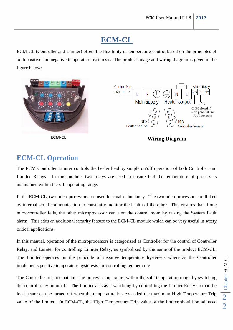
ECM-CL
ECM-CL (Controller and Limiter) offers the flexibility of temperature control based on the principles of
both positive and negative temperature hysteresis. The product image and wiring diagram is given in the
figure below:
ECM-CL Operation
The ECM Controller Limiter controls the heater load by simple on/off operation of both Controller and
Limiter Relays. In this module, two relays are used to ensure that the temperature of process is
maintained within the safe operating range.
In the ECM-CL, two microprocessors are used for dual redundancy. The two microprocessors are linked
by internal serial communication to constantly monitor the health of the other. This ensures that if one
microcontroller fails, the other microprocessor can alert the control room by raising the System Fault
alarm. This adds an additional security feature to the ECM-CL module which can be very useful in safety
critical applications.
In this manual, operation of the microprocessors is categorized as Controller for the control of Controller
Relay, and Limiter for controlling Limiter Relay, as symbolized by the name of the product ECM-CL.
The Limiter operates on the principle of negative temperature hysteresis where as the Controller
implements positive temperature hysteresis for controlling temperature.
The Controller tries to maintain the process temperature within the safe temperature range by switching
the control relay on or off. The Limiter acts as a watchdog by controlling the Limiter Relay so that the
load heater can be turned off when the temperature has exceeded the maximum High Temperature Trip
value of the limiter. In ECM-CL, the High Temperature Trip value of the limiter should be adjusted
Wiring Diagram
C-NC closed if: - No power at unit
- At Alarm state

ECM User Manual R1.8 2013
EC
M-C
L
23
higher than the Controller Set Temperature in order to ensure that the Limiter can restrict temperature rise
by de-energizing the Limiter Relay.
Controller Operation:
See ECM-C Operation on page 11
Onboard Controls:
The user has the option to select the Controller Maintain Temperature and Limiter High
Temperatures Trip values independently in the range of 0°C to 500°C or 32°F to 932°F by
selecting the appropriate Temperature Unit.
One Reset Switch is also present on the module for Auto or Manual reset of the Limiter in case
the temperature of the RTD Limiter Sensor exceeds the High Temperature Trip value.
The Red Fault LED is used to indicate the existing fault detected by the ECM-CL module by
using different delays and flash sequences. A list of faults and flash sequences for the ECM-CL
is given at the end of this chapter. The Red Fault LED can be very useful in determining the
system fault in the case of no communication option or when 4-20mA current loop is being used
as a communication option (not all faults are represented using the 4-20mA current range).
The Green Power LED is used to indicate that the ECM unit is energized from the power terminal.
Limiter Operation
See ECM-L Operation on page 15
ECM-CL Faults
A range of faults are detected and represented using the Fault LED. Faults are also logged in the
EEPROM memory of both the Controller and the Limiter microprocessors along with the operational
time at which the fault was detected. When the ECM does not contain any fault condition, it will send
0x00 as the fault code when requested via the serial communication.
A list of faults is given on the next sheet.

ECM User Manual R1.8 2013
Chap
ter:
EC
M-C
L F
ault
s
2
4
ECM-CL Faults
No Alarm Condition Action Control Relay Limiter
Relay
Alarm Relay Current loop Fault
Code
Alarm LED
(Flash, Delay(s),)
Self Resettable Function & Condition
1. System Fault, Software (Software failure
established in the microprocessor)
De-Energize Limiter/Control
Relay and Raise Alarm*
*De-Energized *De-
Energized
De- Energized Controller
Sensor
Temperature
0x11 (1, one) Yes
(if microprocessor resets) OR
(Fault cleared using the serial comms)
2. System Fault, Communication
(Communication failure established between
the microprocessors)
De-Energize Limiter/Control
Relay and Raise Alarm*
*De-Energized *De-
Energized
De-Energized Controller
Sensor
Temperature
0x12 (1, two) Yes
(if microprocessor resets) OR (Fault
cleared using serial comms)
3. RTD Controller Fault (Controller RTD
PT100 Open/Short1 )
De-Energize/Energize
Control Relay and Raise
Alarm
De-
Energized/Energized
No Action De-Energized < 3.90mA /
> 20.10mA
0x21 (2, one) Yes
(Sensor Repaired)
4. RTD Limiter Fault (Limiter RTD PT100
Open/Short1 )
De-Energize/Energize
Control Relay and Raise
Alarm
No Action De-Energized De- Energized Controller
Sensor
Temperature
0x31 (3, one) Yes
Sensor Repaired)
5. Invalid Maintain Temperature Min
(Controller Maintain Temperature Value <
Min Maintain Temperature value in °F)
De-Energize Control Relay
and Raise Alarm
De-Energized No Action De-Energized Controller
Sensor
Temperature
0x41 (4, one) Yes
(Correct Maintain Temperature value)
6. Invalid Maintain Temperature Max (Controller Maintain Temperature Value >
Max Maintain Temperature value in °C/°F)
De-Energize Control Relay,
Limiter Relay and Raise
Alarm
De-Energized De-Energized De-Energized Controller
Sensor
Temperature
0x42 (4, two) Yes
(Correct Maintain Temperature value)
7. Invalid High Temperature Trip 1 Min
(Limiter High Temperature Trip Value < Min
High Temperature Trip value in °F)
De-Energize Limiter Relay
and Raise Alarm
No Action De-Energized De-Energized Controller
Sensor
Temperature
0x51 (5, one) Yes
(Correct High Temperature Trip value)
8. Invalid High Temperature Trip 1 Max
(Limiter High Temperature Trip Value > Max
High Temperature Trip value in °C/°F)
De-Energize Control Relay,
Limiter Relay and Raise
Alarm
De-Energized De-Energized De-Energized Controller
Sensor
Temperature
0x52 (5, two) Yes
(Correct High Temperature Trip value)
9. Invalid High Temperature Trip 2 (Limiter
High Temperature Trip Value < Maintain
Temperature Value)
De-Energize Control Relay,
Limiter Relay and Raise
Alarm
De-Energized De-Energized De-Energized Controller
Sensor
Temperature
0x61 (6, one) Yes
(Correct Maintain Temperature value)
10. Low Temperature Alarm (Controller Sensor
Temperature > (Controller Maintain
Temperature Value - Low Temperature
Alarm offset value))
Raise Alarm (Control Relay
already De-Energized)
Already Energized No Action De- Energized Controller
Sensor
Temperature
0x72 (7, two) Yes
(Sensor Temperature in differential range)
11. High Temperature Trip Internal (Internal
NTC Temperature >= Max Internal Circuit
Temperature Threshold value)
De-Energize Control Relay,
Limiter Relay and Raise
Alarm
De-Energized De-Energized De-Energized Controller
Sensor
Temperature
0x81 (8, one) Yes
(Safe internal circuit temperature)
12. High Temperature Trip Limiter (Limiter
Sensor Temperature >= Limiter Maintain
Temperature)
De-Energize Limiter Relay
and Raise Alarm
De-Energized De-Energized De-Energized Controller
Sensor
Temperature
0x82 (8, two) Yes
(Auto/Manual Reset OR Module Resets)
AND (Limiter RTD Temperature = Limiter
High Temperature Trip Value)
13. Low Voltage Trip (Mains Supply < 190
VAC/102 VAC)2
De-Energize Control Relay,
Limiter Relay and Raise
Alarm
De-Energized De-Energized De-Energized Controller
Sensor
Temperature
0x92
-------- Yes
(Mains Supply = 204VAC/102VAC)
14. Internal Circuit Temperature >=
100°C/212°F
(Hardware Failure)
ECM will shut down and
damaged permanently,
Alarm Raised (fail safe)
De-Energized De-Energized De-Energized -------- -------- -------- No

ECM User Manual R1.8 2013
EC
M-C
L F
ault
s
25
1 Occasionally open circuit and short circuit conditions of the RTD can be mixed.
2 The fault code will be logged in the microprocessor memory once the module powers up again. This fault indicates that the ECM has gone through a power cycle.
*If System fault is detected by the Controller microcontroller then the Controller Relay will be De-energized along with the Alarm Relay. If system fault is detected by the
Limiter microcontroller then the Limiter Relay will be De-energized along with the Alarm Relay.

ECM User Manual R1.8 2013
Chap
ter:
EC
M F
ault
s an
d A
larm
26
ECM Faults and Alarm
All the ECM modules are designed to detect various potential faults which can arise due to different
reasons such as: RTD sensor faults, operator error, microprocessor failure and software failures. If a fault
is detected, it is logged into the internal memory (EEPROM) of the microprocessor along with the time1
when the fault was detected. The EEPROM is able to store the last 20 faults detected by the ECM. The
user can communicate with the module using RS485 BUS or CAN-BUS to request the current faults
remotely for troubleshooting purposes.
A complete list of the fault codes for all the ECM types is given in their respective sections of the manual.
Every fault detected by the ECM is given a distinctive hexadecimal code which also determines the
flashing sequence for the Fault LED. The user can easily determine a fault code from the flashing
sequence of the Fault LED and by looking at the fault table for the respective ECM module. An example
of determining the alarm from the LED flashing sequence is given in next section.
In the ECM-CL, Controller faults are given priority over Limiter faults when displayed using the Fault
LED. When no Controller fault is present, Limiter faults will be displayed using the Fault LED.
Prioritization of the Fault LED flashing sequence for different ECM modules is summarized in the
following Table:
Module Fault Priority for LED
ECM-C Controller Faults
ECM-L Limiter Faults
ECM-CL Controller Faults. When no Controller Faults, Limiter Faults are given
priority.
1 Please note this is the operational time of the module under power.

ECM User Manual R1.8 2013
EC
M P
aram
eter
Cust
om
izat
ion a
nd P
rogra
mm
ing
27
Fault LED flashing sequence
The Red (Fault) LED is used to represent a fault detected by the ECM. The user can look at the Fault
LED and, from the flash sequence and the delay between flash cycles, determine the cause of the fault.
Flash Cycle: In order to represent a range of faults using one Fault LED, the flash cycle is used. The
flash cycle is the number of times the Fault LED flashes consecutively, with each flash being 0.25
seconds apart.
Flash Cycle Delay: The delay between one flash cycle of the Fault LED and the next, in multiples of one
second.
An example for determining a fault from the flashing sequence of the Fault LED is given below:
ECM Module Type = ECM-CL
Number of consecutive LED Flashes in one Flash Cycle = 7
Delay between each Flash cycle = 2 second
Fault Code = 0x𝑁2𝑁1
𝑵𝟐 = Number of LED Flashes =7
𝑵𝟏 = Flash Cycle Delay = 2
Fault Code = 0x72
From the ECM-CL fault code list, it can be determined that the High
Temperature Alarm was raised by the controller.
ECM Parameter Customization and Programming
For customization and/or programming of parameters please contact Thermon.

ECM User Manual R1.8 2013
Chap
ter:
EC
M C
onfi
gura
tion P
aram
eter
srs
28
ECM Configuration Parametersrs
No Description Min Max Default Units
1 High Temperature Trip value for Internal Thermistor 0°C /32°F 85°C /185°F 85°C /185°F °C / F
2 Temperature Differential Type Temperature Offset % Temperature Offset °C / F
3 Control/Limiter Temperature Control Band 3°C / 5°F 100°C / 212°F 3°C / 5°F °C / F / %
4 Low Temperature Alarm offset value 3°C / 5°F 100°C / 212°F 3°C / 36°F °C / F / %
5 Control/Limiter Relay ON Delay 0 60 5 Seconds
6 Control/Limiter Relay OFF Delay 0 60 5 Seconds
7 Alarm Relay ON Delay 0 60 10 Seconds
8 Alarm Relay OFF Delay 0 60 5 Seconds
9 Control RTD Open Circuit (Action on Control Relay)1
0 1 0 None
10 Control RTD Short Circuit (Action on Control Relay)1
0 1 0 None
11 4-mA Scaling Temperature 0°C /32°F 500°C /932°F 0°C /32°F °C / F
12 20-mA Scaling Temperature 0°C /32°F 500°C /932°F 500°C /932°F °C / F
1 Only Available in ECM-CL