Electronic Construction Coordination with AutoCAD
79
Engineering Management Field Project Electronic Construction Coordination with AutoCAD By Christopher Neal Fall Semester, 2007 An EMGT Field Project report submitted to the Engineering Management Program and the Faculty of the Graduate School of the University of Kansas in partial fulfillment of the requirements of the degree of Master’s of Science Charles Keller Committee Chairperson Tom Bowlin Committee Member Annette Tetmeyer Committee Member Date Accepted:
Transcript of Electronic Construction Coordination with AutoCAD

Engineering Management Field Project
Electronic Construction Coordination with
AutoCAD
By
Christopher Neal
Fall Semester, 2007
An EMGT Field Project report submitted to the Engineering Management Program and the Faculty of the Graduate School of the University of Kansas in
partial fulfillment of the requirements of the degree of Master’s of Science
Charles Keller Committee Chairperson
Tom Bowlin Committee Member
Annette Tetmeyer Committee Member
Date Accepted:

2
Executive Summary
A key component to the construction process is drawing coordination. Due to the
fast paced nature of today’s construction, many design firms utilize other consultants to
aid in completion of the documents within the required design time frame. Coordination
between consultants is often neglected as the design is completed. Additionally,
traditional coordination methods utilize hard copies and light tables for coordination of
construction drawings. Therefore, it is desirable to create an improvement plan that
utilizes electronic coordination for the construction process.
Modifying the coordination process to a soft format that utilizes AutoCAD design
software would improve quality and accuracy. The improvement plan also included
changes to the bid process and job buyout. Shop drawing development was required to
be completed utilizing zone and layer control. Drawing guidelines were developed to
simplify compiling of multiple files into a single drawing.
A key aspect of this project was document management. Files were produced
using specified layer control, labeling requirements, and drawing standards. A third
party was hired to manage an FTP site for storage and movement of files. This system
ensured the current files were available for use and the older files were archived.
The construction coordination process requires three stages, drawing
coordination, field coordination, and as-built development. The majority of coordination
is completed during the drawing coordination stage. Field coordination is utilized to
correct for errors and problems created by overlapping tolerances and installation errors.
The work in place is then documented to insure the drawings are updated to provide
accurate as-built drawings for the client.
The program provided improvements to the existing system and achieved a basic
level of soft format coordination. This system improved speed, lower costs, and allowed

3
individual sketches of specific items to be produced for review. The use of layer control
allowed for plots to be produced showing only the layers critical to the specified
application. This uncluttered the view and made a more useful drawing.
The information learned from implementing this process has identified areas that
should be improved prior to repeating the process. Additional time should be devoted to
training participants in the use of the available resources, labeling conventions, naming
conventions, and drawing standards. Other areas that created problems were
inconsistency in the drawing packages and third-party plug-ins used by subcontractors.
Further investigation identified many of the plug-ins were required to support their shop
manufacturing processes and could not be eliminated.
Further work would be to use the information gained during this project for
improvement of the implementation of a Building Information Management (BIM) system.
The architectural design packages are currently set for developing drawings in 3D. The
BIM system adds a database of critical component information which is packaged with
the drawing. The mechanical and electrical trades have not adapted the new formats for
design at this time. The mechanical and electrical software designers are still in work on
development of the BIM design packages. Once this step is complete, the program will
contain all critical parts to being a fully operation system.

4
Table of Contents
Executive Summary .......................................................................................................................... 2
Construction Definitions & Roles ..................................................................................................... 5
Role of Participants .......................................................................................................................... 8
Explanation of Construction Design Procedures ........................................................................... 11
Literature Review ........................................................................................................................... 14
Background of development of AutoCAD .................................................................................. 14
Agile Project Management ........................................................................................................ 15
Agile Project Management Summary ........................................................................................ 17
Introduction ................................................................................................................................... 19
History ............................................................................................................................................ 21
Background of coordination utilizing traditional methods ........................................................ 21
Transition to soft copy coordination ............................................................................................. 23
Architect / Engineer design phase ............................................................................................. 25
Bid Process / Job Buyout ............................................................................................................ 27
Shop Drawing Development ...................................................................................................... 28
Mechanical / Electrical Coordination ......................................................................................... 29
Document Control...................................................................................................................... 30
Field Coordination ...................................................................................................................... 34
As‐build documentation ............................................................................................................ 35
Results ............................................................................................................................................ 37
Suggestions for Additional Work ................................................................................................... 42
Bibliography ................................................................................................................................... 44
Appendix ........................................................................................................................................ 46
Appendix A – Naming Convention for Layer Management ....................................................... 46
Appendix B – Sample Drawing Schedule ................................................................................... 48
Appendix C – Sample Meeting Minutes ..................................................................................... 51
Appendix D – Extranet Site Screen Shots ................................................................................... 55
Appendix E – Commissioning Plan Extranet Training / Instructions .......................................... 59

5
Construction Definitions & Roles
As‐Builts – are a record set of drawings that show the actual installation of the work. These
drawings are not finalized until after the work in completed. To maintain accuracy, the
coordinated drawings must be updated to show variations as the work is installed. The
intermediate step is called “red lines”.
Column Lines – is a grid system in construction documents to aid in the ability to identify a
specific location on the drawings or in the field. One access utilizes letters and the other utilizes
numbers. There is a consistent spacing between each line. An example would be C17. This
represents C on the x‐axis, and 17 on the y‐axis.
Conceptual Design – is the first design produced. It attempts to provide a general description of
the project. The intent is to allow the client to get an initial view of the designers understanding
of the project.
Design Build – is when the owner holds a single contract with a company who is responsible for
both design and construction of the project. The Architects, Engineers, and Construction
Management are all considered to be the same team from the view of the client. In many cases,
the team is a joint venture between companies that specialized in each area.
Detailed Design – This design incorporates all necessary information for construction of the
project. It is produced by the Architect and utilized by the Construction Manager for bidding
and awarding the work. This document is the basis for the subcontracts.
Document Management – is the system used to manage and control the distribution and
archival of the construction drawings, RFIs, addendums, contracts, correspondence, etc. Most

6
projects require a system for managing soft and hard copies. The system must also provide a
method for correlating the two systems.
Drawing Coordination – is the process of resolving any conflicts between the individual trade
shop drawings. This process is completed prior to the work being installed. The intent is to
prevent rework from conflicts found during installation.
Drawing Standards – this is a guideline produced to insure all designers are producing
documents in the same manner. These standards will define things such as scale, labeling, units,
call‐outs, details, fonts, text, layers, etc.
Fast Track Construction – is the system where construction begins prior to completion of the
construction documents. The early packages are released for construction based on current
information available, assumptions of future requirements, and experience from similar
projects. The goal is to shorten the project duration to accelerate the completion date.
HVAC – Is the abbreviation for heating ventilation and air conditioning. This term is commonly
used to describe the contractor or tradesman that installs these systems.
Job Buyout – is the process of hiring subcontractors to complete specific portions of the project.
The process defines the work and compensation for the work. A contract is produced to
document the agreement.
Labeling Convention – is the system for providing documentation to the drawings. This system
must be defined to insure consistency between drawings from different trades.
Layer Control – AutoCAD documents utilize multiple layers to manage the large amount of
information. To control the visible information, the names and organization of these layers

7
must be controlled. To allow the files of multiple trades to be combined, the systems and
methods used must be consistent.
Light Table Coordination ‐ is the traditional method of coordination between multiple trade
shop drawings. The light table has lights below a transparent work surface. When two or more
drawings are placed on the work surface with the light energized, the lines from the lower
drawings will be visible through the top drawing. The drawing is reviewed for locations where
the lines intersect. These areas are then checked to see if a conflict exists. The process is
inefficient because the drawings are produced in 2D. It is possible for the lines to intersect
without a conflict since the items could be at different elevations. Every intersection must be
manually reviewed.
Schematic Design ‐ is a preliminary design that establishes scope and relationships of the
systems. The client’s expectations are defined and reviewed. An initial budget and schedule is
created to verify compliance with the funds available. This design does not provide adequate
detail for construction.
Scope Creep – is when the design gradually implements small changes that combine to make a
major impact on the scope and cost of the project. The results of scope creep are usually a
design that far exceeds the actual needs of the program.
Scrubbed Backgrounds – are drawings that have had all extraneous information removed. For
coordination, unnecessary information clutters the drawings when compiled. A few examples of
things that would be removed are, drawing notes, title blocks, revision identifiers, and site
reference diagrams.

8
Shop Drawings – drawings produced by the subcontractors depicting their understanding and
interpretation of the contract drawings. These drawings expand all drawings dimensions to the
correct scale. These drawings may be produced in 2D or 3D depending on the system and
abilities of the subcontractor. These drawings are submitted to the Architect or Engineers for
review to verify the correct understanding of the work. Once approved during the review
process, these drawing are the basis for the coordination process.
X‐Ref (External Reference) – items that are required to be the same for all drawings are
incorporated into the drawing as an external reference. An X‐Ref is a pointer to a separate file
that contains this information. The benefit of using X‐Refs is that changes are universal to all
drawings. Some items typically included in the X‐Ref files are column lines, title blocks, wall
layouts, and site elevation references.
Zone Control – when designing a building, each trade should be assigned spaces for the system
to be installed. These spaces are called zones. The intent is to prevent overlapping these zones.
If zones overlap, there is potential for a conflict between the systems in each zone. It is
common for there to be areas where overlapping the zones is unavoidable.
Role of Participants
Client
The client is the owner of the project. They hire the Architect and Construction
Manager. If the client chooses to simplify or reduce their required interaction, they may have
either the Architect hire the Construction Manager or the Construction Manager hires the
Architect. This will allow them to have a single point of contact and avoid problems between

9
the two groups. In most cases the client will contract directly with each to provide a means of
checks and balances.
The design is dependent on interaction between the client and consultants. The
information provided by the client provides direction for the design. Throughout the design
process, the client should have an opportunity to review the progress and adjust the direction
and scope if necessary. The client has ultimate authority in any conflicts between groups.
Architect
The Architect works directly for the client. They are responsible for the design of the
project. The final design is produced through a multiple step process. Each step is reviewed with
the Client to insure it meets intent and budget. The Architect may produce all work with their
personnel or may hire consultants to complete portions of the design. When consultants are
used, the consultant delivers all information to the Architect who compiles it into the
construction documents. The Architect is responsible for the review of all shop drawings to
insure they meet the design intent.
Engineer
The Engineering Firm designs specific portions of the project as defined by the Architect.
Engineering companies are typically used to complete the mechanical, electrical, and plumbing
design. The documents produced by the Engineering Firm are delivered to the Architect for
incorporation into the design documents.
Engineering firms are also used as consultants for specialized systems. Depending on
the size of the system and amount of documents required to be produced, the firm might not
produce any design documents. In this situation, they only provide suggestions or

10
recommendations to the entity producing the design documents. An example would be the
layout of speakers for the public address portion of the fire alarm system. The consultant
provides recommendations to achieve proper coverage, but the design is produced by the
engineer designing the fire alarm system.
Construction Manager
The Construction Manager (CM) is hired by the client to insure that construction is
completed on time and within budget. The firm is expected to act in the client’s best interest.
The CM is most effective when they are selected early and included through the entire project.
During the conceptual design phase the CM provides valuable feedback on construction issues,
such as site conditions, permits, labor issues, and contractor prequalification. Budgets are also
established based on initial design information and historical data. As the design is refined, the
estimates and schedule are updated to reflect changes and provide a more accurate estimate of
project costs and schedule. This is essential to minimize scope creep.
During the construction phase, the CM controls the information flow between all
participants. This includes the client, architect, engineering firms, specialty consultants,
subcontractors, and vendors. They review construction progress and budgets to insure they are
staying within the specified guidelines. The CM is responsible for review of the coordination
drawings. Upon completion of the project, the CM insures all close out and record
documentation is completed.
Subcontractor
The subcontractors are the firms that perform the work. They can be hired by the
Construction Manager or directly by the Client. To transfer liability, the client typically has the

11
CM hire the subcontractors. This allows the client to have a single contract with the CM that
provides grantees of performance and costs of the subcontractors as a whole.
Each subcontractor is hired to perform a specific scope of work. The subcontractor is
required to produce all shop drawings and coordinated drawings associated with this work.
Vendor
The vendor is hired by the subcontractor to provide materials and equipment for the
project. The list of acceptable vendors is typically created by the Architect and included in the
specifications. The vendor provides cut sheets and detailed product drawings for the equipment
they will be providing. The cut sheets detail the space and services required by the equipment.
In addition, and service and access requirements are outlined. This information is incorporated
into the drawings as they are transformed from shop drawings to coordination drawings.
Explanation of Construction Design Procedures
The construction design for this project is completed in 6 steps. The initial 3 steps are
completed by the architects and engineers. The second 3 steps are completed by the
subcontractors. The following chart shows the flow of the process.
The conceptual drawings are produced by the architect based on early conversations
with the client. This step usually does not incorporate input from the engineering firm or the

12
construction manager. Owner comments and requested revisions are not incorporated until the
schematic drawings are produced.
The schematic drawings incorporate input from the engineering firm and other
consultants hired by the architect and owner. These drawings are revised and re‐issued until
the client accepts the design and releases the architect to produce detailed drawings.
The detail drawings provide the full design intent. The architect, engineer, consultant,
and construction manager provide feedback for improving the quality of these documents. They
are utilized for bidding the work. Once the work is bid and contracts awarded, these drawings
become the “contract documents.” Any changes to the design from this point forward require a
modification to the contracts.
The shop drawings are produced by the contractors awarded the package to complete
the work. The intent of the drawing is for the contractor to demonstrate their understanding of
the design while incorporating the specified product data. These drawings must accurately
show equipment dimensions, access spaces, code required clearances, interactions with other
systems, and adjustment for constructability. The drawings are initially reviewed by the
construction manager. Upon acceptance, the shop drawings are forwarded to the architect /
engineer team for approval.
The coordination drawings are produced by the subcontractor after the individual shop
drawings are approved by the architect / engineer. These drawings are reviewed by the
construction manager. Upon approval, each contractor is required to sign the drawing sheets
agreeing the layout will work in harmony with their work. The coordinated drawings are not
reviewed by the architect / engineer.

13
The as‐built drawings provide a record of the actual installation of the work. The
drawings are produced by each contractor and forwarded to the architect through the
construction manager. The architect converts the as‐built to the clients preferred format for
archival and future maintenance.
The focus of this project was to improve the coordination drawing stage of the process.
In addition to changes to the coordination stage, accomplishing this task required modifications
to the previous step of producing shop drawings as well as modifications to the following step of
developing as‐built drawings.

14
Literature Review
A literature review was completed to find previous research on the use of
AutoCAD as a coordination tool and study Agile Project Management (APM). There was
no information available on other projects that have used the AutoCAD software in the
same manner intended for this project, however there was a large about of information
providing guidance of implementing APM.
During the AutoCAD research, the search criteria was expanded to include
information on the use of AutoCAD as a design tool and was further expanded to
research its use in a multiple consultant environment. The resource list remained
limited and nonspecific to the desired topic.
Background of development of AutoCAD
AutoCAD is a three dimensional design software package developed by
Autodesk. The first version was released in 1982. In the past 25 years, there have been
21 major revisions. John Walker, the founder of Autodesk, has published the online
book , “The AutoCAD File” providing the history of the development of AutoCAD and his
visions for future improvements.
The key feature for coordination utilizing AutoCAD is the ability to create
drawings in 3D. The initial plans to implement 3D design were introduced in 1983. This
vision lead to the incorporation of the x,y.z axis on the work space. The early versions of

15
the software did not actually draw in three dimensions. The program was only capable
of producing a two dimension drawing, that mimic the appearance of a 3D drawing
observed from a single view. For each view that was required, a new drawing would
have to be created. The document outlines the numerous steps required to develop
the tools required to move from the initial 3D attempts to the current true 3D revision.
This development background included in the text will provide a better understanding
of the design of the user interface and software engine powering the software.
Agile Project Management
A key component to success for this project is managing the changes that must
be implemented. The construction environment changes quickly and often. The
management system must be capable of reacting at the same pace. The solution is
developing an Agile Project Management system. Although this project appears to be
an improvement to a construction process, the core changes to the systems are actually
software development and project management improvements.
The Pace Systems manual published in 2003, “Agile Project Management” by
Sanjiv Augustine and Susan Woodcock was reviewed. This manual identifies the keys to
a successful implementation of APM. The key sections are the definitions of the 6
factors that must be incorporated for a successful implementation. The optimal use of
this document would be to provide a basic understanding of APM to the project team as
well as guidance on the operation and procedures. Even though it was based on
software development systems, the guidance provided is universal to all APM systems.

16
The international Journal of Agile Management published the article, “Web‐
based Information Access for Agile Management” in 2000. The transition from
traditional systems of data management to use of internet and extranet is explained. In
addition to developing new systems to optimize the data management process, it is
necessary to maintain compatibility with legacy systems and information. The default
solution is to develop backwards compatible applications. This method can limit the
capabilities of the new system. An alternate solution is to build new systems
independent of concerns of maintain compatibility with older systems and utilize stand
alone applications to convert older data to a compatible format. Numerous other
options for utilizing web based systems for document control and distribution are also
defined. Most applications are only compatible with a very small selection of these
alternate options. The descriptions included provide a general overview requiring
additional research prior to implementation.
A detailed explanation of the required employee involvement is outlined in,
“Importance of Employee Involvement in World‐Class Agile Management Systems”
written by Yaw Owusu in 1999. Teams should be formed with the intent to improve the
system they will work within. Beyond selecting team members, the proper team
management skills should be used to optimize the results. This optimization requires
proactive management involvement and strong two way communication. The author
provides numerous recommendations that would require a significant amount of
commitment from all levels of the organization throughout the duration of the project.
The article does not address methods to motivate employees to abandon traditional

17
methods for the new concepts. It suggests that good communication will suffice but
does not provide supporting information.
Agile Project Management Summary
There are 6 factors that must be incorporated for a successful implementation.
The first is establishing clear guidance. All participants should know the goals of the
project and understand the leadership’s vision. As the process evolves, adjustment to
these goals must be disseminated to all participants. Since the leadership cannot be all
places at once, it is important the other team members understand the leadership’s
intent to allow continued adjustments to the changing environment.
Teamwork and collaboration are required to optimize the results. Each team
member brings unique skills and perspectives to the project. By leveraging these
resources, the output will exceed the total of the individual contributions. Attitude
plays a significant role in the performance of the team. When the team members enjoy
working together, the work product improves.
Rules are necessary for the smooth operation of the team. These rules should
be kept as simple as possible to provide maximum flexibility. The character of the team
will develop more complex behavior specific to the requirements over time. Keeping
the rules simple will allow this complex behavior to evolve with the project without
limitations.

18
Continuous distribution of the information is critical for supporting a system of
constant change. The team can only respond and adapt to the information available to
them. Open communication must be established and maintained. All members should
be informed of the big picture.
Only enough control to maintain order should be implemented. Having to much
control limits the effectiveness of the team. The leadership should focus on keeping the
project heading in the right direction by not controlling individual activities. Whenever
possible, provide the maximum latitude to team members to accomplish tasks.
The final step is to monitor the results and adjust the system as necessary. This
should be done by team members as well as team leaders. Any participant should have
the ability to recommend a change. Ideas that produce positive results should be
expanded while the concepts that don’t work should be revised. This is an ongoing
process which lasts for the entire duration of the project.

19
Introduction
Drawing coordination is a critical component during the industrial construction
process. Traditionally, the majority of this process would be completed by the design
firm. These firms would develop and implement zone control for the different trades
within the space available as part of the design process. When the drawings were
issued for construction, they were adequate for use in constructing the project.
The need for a faster pace of construction to maintain market competitiveness
has changed this process. To expedite the design process, the design firm develops a
set of assumptions for the requirements of the structure. Basic requirements and
minimal zone control is included as part of the design directive. These assumptions and
criteria are sent to multiple design groups for concurrent completion of the design.
Since all designers are working independently and assumed to be maintaining the
criteria established initially, additional coordination is deferred until the construction
phase.
During the design phase, additional information is obtained through client
feedback or design development. Each consultant is expected to incorporate these
modifications as the design documents are developed. It is assumed this
implementation continues to maintain the initial requirements and zones. The final step

20
is to compile each consultant’s documents into a print package to be issued for bid or
construction.
The flaw with this system is the individual packages from each consultant are
never compiled into the same drawing. To provide a similar appearance, the packages
utilize the same initial background. When the documents are printed, they appear to
have been produced as a single design when in reality they are multiple completely
independent designs. In some cases, the architecture firm is in a different region of the
country than the engineering firms and specialty consultants complicate communication
during joint development of the design.
The solution to resolving conflicts during the construction process is to
implement an extensive coordination process during preconstruction and construction.
This process was traditionally completed utilizing hard copies of the prints, light tables
and red pens. This process is expensive and inefficient due to the resources required to
produce full size prints, markup changes by hand, document changes, produce copies
and distribute the information.
This document provides a description of the methodology used and results
obtained from modifying our coordination process to utilize AutoCAD and working
primarily with soft copies of the contract documents. This project report is divided into
four groups. The sections chosen were a Literature Review, Review of Procedure and
Methodology, Report of Results, and Suggestions for Future Work

21
History
Background of coordination utilizing traditional methods
With the movement towards increased use of “fast track” construction, a strong
coordination program is essential to the success of the project. In the past, the
architects and engineers would have adequate time to complete the design and design
review process prior to the start of the construction activities. Today’s construction
typically incorporates a design build approach. This approach allows the schedule to be
accelerated but also prevents coordinated drawings from being produced by the design
firm prior to construction.
An additional problem is the pace of construction is much quicker than the pace
that updated drawings can be distributed and incorporated. During fast paced
construction, the architect and engineer might only provide a schematic design. The
individual contractors develop these schematics into shop drawings. The shop drawings
are reviewed and then coordinated with other trades. Often this work is occurring after
the building foundation work as begun.
The traditional hard copy coordination system falls apart during coordination
because there is not enough time for contractors to incorporate other contractor
changes and complete their own design while maintaining the project schedule. Each of
the contractors are constantly tweaking their design to meet space and performance
requirements. Since the contractors do not have time to incorporate other contractor

22
changes, these changes are not reflected or considered when developing their drawings.
Information is missing or neglected as the final design is developed.
Another problem caused by the traditional system is increased mistakes during
the field installation. This leads to problems such as the systems not fitting due to space
being encroached on by other trades, performance being reduced by modifications
made in the field, and increased costs due to rework. The most costly problem is
schedule delays due to redesign time.
On a typical project, the coordination process did not start until after the shop
drawing process was completed. Each contractor would develop their shop drawings
independently. There would be an independent review of the shop drawings by the
design engineer. The design engineer comments would be incorporated and final shop
drawings produced.
The coordination process would start by each contractor bringing hard copies of
the final shop drawings to a coordination meeting. At this meeting, the drawings would
be reviewed and conflicts identified. Many conflicts were not detected due to using two
dimension drawings to review a three dimension design. More conflicts are usually
discovered in the field during installation.
The challenge has been increased by the requirement to fit more services within
the same or less space as buildings become more automated. The traditional methods
do not provide the flexibility and speed required to maintain the project’s momentum.
In the past, the most common method for detecting clashes was the use of light tables.

23
Each trade would use the prints they provided at the meeting in conjunction with a light
table. Where the services crossed, the area would be investigated to see if there was a
conflict. For this method to work, all drawings had to be in the same scale and utilize
the same match lines.
Light table coordination is still used, but it is not as effective as electronic
methods. As more sheets are required to be overlaid, the ability to cast enough light
through the stack decreases. Without adequate light, it is not possible to identify the
clashes. The common solution is to compare 2 to 3 drawings at a time and then
exchange prints until all necessary combinations have been reviewed. Upon
identification of the clashes, the drawings must be revised and reproduced and that
area reviewed again. Depending on the number of trades involved, this process can
become very time consuming and cumbersome.
Another flaw with the light table method is the inability to produce a single
coordinated sheet. Each area will require a stack of drawings that represent the final
shop drawing for each trade. This creates problems for an owner to maintain a large
stock of maintenance drawings each showing a part of the work. It also creates
difficulty for contractors if a future change needs to be implemented, the contractor
must review multiple drawings to insure the work will fit.
Transition to soft copy coordination

24
The goal of this project was to implement a coordination process through the
use of AutoCAD. The contractors were directed to use the same CAD program and
version for completion of their shop drawings. The HVAC contractor and Piping
contractor also used these programs to export instructions to their fabrication
machines. All contractors had previous experience with a version of AutoCAD prior to
beginning the project.
During the bid process, it was clarified that all contractors were required to
complete their shop drawings utilizing AutoCAD 2004 to 2006. This was to insure file
compatibility between trades. All drawings were to utilize the “scrubbed” backgrounds
and x‐refs and be printed in ¼” scale. These base files were created by a third party
CAD development company. The labeling conventions and layer control requirements
were also outlined and defined by the CAD house. (Appendix A)
The program plan required each contractor to post their current drawings on
Friday between 7AM and 3PM CST. This would allow the database administrator to
search for files by time window to insure they collected the most current files. These
files were then compiled into a single drawing that would be reviewed during a Tuesday
coordination meeting. During the meeting, clashes would be identified and a solution
suggested. The contractor would then implement a rough version of the fix for the
Thursday meeting. This meeting would utilize 8x11” sketches showing specific areas for
review. The smaller sketches were able to be printed locally on personal printers. This
eliminated added costs and time for a printing shop to produce full size plots (30 x 42”).

25
If a proposed solution was found, the drawings were updated from the marked up
sketches and posted by the following day. If the problem was not solved, additional
sketches would be produced for the following meeting.
Prior to starting this project, no member of them team had experience sharing
drawings outside of their own company utilizing AutoCAD. Each contractor had
implemented a program within their company only. The companies that performed
multiple areas of work were able to seamlessly share drawings between trades in house.
The assumption was that this process could be mimicked when working with other
contractors.
The initial steps were to establish a naming convention, layers, labeling style,
dimension style, and contractor colors. Each contractor was expected to complete their
shop drawings utilizing the detailed design documents produced by the Architects and
Engineers as a basis for this work, the outlined criteria for production of their drawings
was established prior to commencing work. Upon approval of their shop drawings, the
consistency in document development allowed the individual shop drawings to be
compiled into a composite set to start the coordination process.
Architect / Engineer design phase
To build a successful AutoCAD coordination process, the original design
documents must be designed to support the effort. It is typical for an architectural firm
to hire an engineering firm to complete the mechanical and electrical portions of the
design. The engineering firm will use the same background, but produce the drawings

26
independent of the architectural drawings. In some cases, the engineering firm also
produces mechanical and electrical drawings independently. When the drawings are
produced with this method, they cannot be assembled into a single package. One
package must be chosen as the base drawings and all other trades redrawn into the
proper file format.
The most effective approach would be to have coordination controls
implemented during the initial design of the process. The detailed design drawings
could then be used as the basis for coordination without the need for rework. Instead
of redrawing the package, the drawings would then just require modifications to
incorporate improved information to expand the single line drawings to a 2D rendering
or develop 3D drawings utilizing the established document package.
If possible, it would be best to have the project designed in the 3D workspace.
This would allow for initial coordination to occur during the design process. As the
drawings were being produced, the congested areas would be apparent and could
possibly be avoided during this phase. This process could be automated using a 3rd
party collision software package. Most architectural firms are opposed to this method
due to fear of increased liability for errors found during coordination. The errors should
have been apparent during the initial document development since the documents
were produced and combined in 3D during development.

27
Bid Process / Job Buyout
It is essential to clearly define the requirements and expectations during the bid
process. Producing documents that meet the required criteria requires the draftsmen
to have a good understanding of the program packages that have been selected. Many
contractors use 3rd party CAD programs or plug‐ins that support their manufacturing
processes. During the bid process, the requirement to use a specific project must be
identified. These additional requirements and software must be accurately identified
and analyzed for compatibility during the bid phase. Any special requirements should
be included in the job buy out and included in the contract documents.
The required participation and time commitment expectations must also be
included in the negotiations. It is imperative the tasks are properly staffed to allow the
program to function at the necessary pace. The team for each company requires a
project manager to insure the progress is working in a direction that supports the needs
of the project. Within the team, it is necessary to have participants that understand the
means and methods of field installation and the operation of the system to be installed.
This member should also be able to provide suggestions for resolving issues they have
previously experienced. They also provide feedback when an idea creates a problem
that could not be implemented in the field.
There are two groups that manage and develop the drawings. The first is the
database/FTP site manager. Their primary responsibility is storage and assembly of the
documents. With the large number of drawings that are constantly being changed and

28
moved, a robust system is needed to insure the right people have the right information.
The draftsmen are the second group and they produce the actual drawings. They must
have the ability to convert the detailed design drawings, contract drawings, marked up
sketches and notes into the coordinated drawings. They will also have the responsibility
of managing the naming of the files and organization of their layers to insure they
remain consistent with the criteria established.
The final requirement is personnel to serve as document control. As new
drawings are being produced each session, the changes that affect work currently or
soon to be installed must be distributed to the installation crew prior to the start of this
work. They must also audit the prints in the field to insure the proper prints are being
used. This process must be completed by all participants in the project.
Shop Drawing Development
Developing shop drawings is the predecessor to coordinating the work. Design
documents typically show the intent of the design. The contractors must complete the
design and confirm all calculations. These drawings provide all the critical size and
layout information for the system. Once the shop drawings are complete, they must be
reviewed by the Engineer of Record (EOR). Any adjustments or changes required by the
EOR must be implemented and drawings resubmitted. This process could repeat
multiple times depending on the complexity of the system. Once the EOR is satisfied
the contractor has demonstrated an adequate knowledge and understanding of the
work, the drawings are approved and the coordination process may start.

29
Mechanical / Electrical Coordination
Once the contractor received confirmation the shop drawings have been
approved, they must be prepped for use in the coordination process. All extraneous
information must be removed to prevent the composite coordinated drawings from
being cluttered to a point of uselessness. Proper layer control allows this process to be
completed quickly. The layers are assigned to insure shop drawing information that is
not necessary to the coordination process is located on independent levels that can be
turned off. In some instances, this addition information is required when a field
installation print is produced for the field foreman. If proper layer control does not
occur during the initial drawings, a new layer must be created and needed information
transferred over. Typically the quickest way to correct this issue was to make a copy of
the layer and delete the extra information from the layer that would be used during
coordination.
Additional information is required to be added to the title boxes once the
coordination process starts. These boxes must identify the area and systems included.
It must also provide a means for identifying the revision of the drawing. The final
addition is a signature block for each contractor to sign to confirm they can install their
work in harmony with the other trades. This is critical for insuring the drawing
accurately identifies their routes.

30
Document Control
Implementing an AutoCAD coordination process requires a significant document
control effort. It is essential for all contractors to use the correct set of drawings
throughout the process. As each contractor completes updates, the project files must
also be posted for other contractor’s use. The completed drawings must then be
distributed to the field personnel for guidance in the installation of the work.
The initial step in document control is establishing a system for storing and
distributing the files. This project utilized a web based system managed by a third party.
Based on the expectations of the project documentation, an extranet site was
developed (Appendix D). This site provided areas for each step of the coordination
process as well as posted submittals. Within these areas, a tracking system was
implemented to notify users the status of each drawing. Design of this system provided
an expected project flow to insure the proper sequencing of the drawing production
(Appendix B). As a task was completed, a notification is sent to the next contractor to
begin their work. This process repeats until all contractors have fulfilled their
requirements.
With daily updates being posted to the working folders, the older versions must
be archived so that only the current file is listed. The archival process utilized 3 levels.
The initial archival placed the recent drawings within a folder in the work area. This
allowed a quick comparison of recent changes. If the proposed solution created new
problems, an evaluation could be made to establish if the process should continue or
31
revert to the previous drawing and attempt a new solution. Typically, two weeks of
revisions were kept within this folder.
The second level of archival moved the older files out of the work area into an
archival section of the Extranet. These files are compressed and all plot versions (Adobe
PDF and AutoCAD DWF drawings) are removed to save storage space. These files are
accessible to review the process history, but are not used in the current coordination
process. The files could still be plotted from the drawing file (AutoCAD DWG) but it
requires the full document collection to be present within the same file. The plot files
suitcase all necessary information into a single file for simplicity in movement and
distribution of the file for people that do not requiring editing ability.
The final step of archival removes the files from the extranet system. Three
copies of the files are burned onto 100 year compact discs. Following the recording
process, these CDs are tested and then distributed to 3 locations to minimize the risk of
catastrophic loss. One copy is maintained at the jobsite and the other copies are
distributed to the Extranet Company and the owner’s rep. The contents of each CD are
cataloged for future reference.
The extranet server utilizes 2 servers located in different geographic regions.
Each server is capable of completely operating the extranet independently. The servers
were designed to sync the data to insure both servers contained the same information.
Additional protection was implemented by utilizing an automated daily backup each
evening. Each back up drive stores independent images of the last 7 days on separate
32
drives. The data is replaced utilizing a first in, first out system. An addition monthly
backup is also part of the automated system. This system captures 2 days of images
each month. The capacity of the backup storage space is sized to have the ability to
store 24 months of full project design images. The monthly recording process also
utilizes a first in, first out overwrite protocol.
The daily operation required an accurate way of identifying the current files and
updates. This feature was incorporated into the Extranet. Once implemented, the
process was then automated to eliminate the probability of operator error from
manually completing this task. As new files are posted, they are manually consolidated
into a composite drawing. This process requires 2 days to complete and plot. To insure
the proper files were compiled, each contractor was required to post the files they want
compiled on Fridays between 7AM and 3PM CST. The Extranet Contractor sorted the
information by this time window to select the files for assembly. If a new file was not
posted during the posting window, the old file was left in place.
Another issue that must be managed is the labeling of the files. Since AutoCAD
imports X‐Refs by name references and location within the same folder, proper naming
is essential. As part of the assembly process, each file is renamed to match the
expected name. The files are then copied into the assembly folder. Within this folder, 3
versions of the drawings are produced. The DWG is an AutoCAD drawing format. It
allows for the file to be edited. It also allows selection and hiding of levels. All files in
the assembly folder are required to view or plot the complete drawing. The second

33
format is a DWF file. This is an AutoCAD plot file. All needed information is suitcased
within a single file. Utilizing a plot file retains the ability to manipulate the layers and
plot the file only. These files cannot be edited in this format. Viewing the DWG or DWF
files require AutoCAD software or an Autodesk DWG or DWF viewer. The software must
be purchased and licensed but the viewers are available for free download on the
AutoCAD website. The final version is a PDF. The PDF format is typically used to
distribute the information to people outside the coordination group. This format allows
for viewing of the files using Adobe Reader or Adobe Acrobat. The file only provides the
view of the layer format at the time of conversion. If multiple views are required, a PDF
must be produced for each view. To limit wasted effort, the PDF file is produced as the
final step of each area of coordination.
File size will also become a problem if the layers are not properly managed. As
each contractor is using the x‐refs to produce their layers, there is a potential for there
to be repeated layers when the files are combined. In most cases, unnecessary layers
are turned off to remove them from view, but they still occupy space within the file.
The solution was to direct each contractor to extract and submit only the specific layers
assigned to their trade. The X‐refs would already be present in the assembly folder.
Without this process, each contractor increased the file size by 84 layers of repeated
data. The files for each floor grew, in one case the repetitive data caused the file to
grow to approximately 2.5 gigabytes instead of the typical 50 – 150 megabytes.

34
As new files are completed, the final product must be plotted and distributed.
These copies must update the office drawings as well as the field drawings. The update
process must track all files currently being used on the job and remove outdated files
from use. Due to printing costs, the contractors are hesitant to constantly update
drawings for minor revisions. The contractors preferred solution would be to redline
the existing drawings. For the drawing update and removal process to be successful,
the Construction Manager must perform regular audits to force compliance. Any costs
created from use of outdated drawings must be tracked, quantified and passed on to
the offending contractor. An alternate lower cost option to replacing full size plots for
minor changes would be to issue 8 ½” x 11” sketches produced from the updated
drawing file. These sketches would then be issued and inventoried during the drawing
audit.
The final step is to produce detailed field sketches for use for specific areas of
complex installation with interactions between trades. These sketches provide sections
of critical areas on 8” x 11” or 11” x 14” pages. These forms are significantly more
manageable in the field than a full size 30” x 42” plot. Some contractors also opt to use
half size prints. Currently, the capability to produce these plots in house does not exist.
Therefore, this requires the full size prints to be sent to a copy house that will scan and
print ½ sizes for an additional fee.

35
Field Coordination
Field coordination occurs when the coordinated drawings do not work with the
field installations. These problems can be caused by numerous reasons. The most
common is installation error. Another cause is the cumulative effect of allowed
tolerances. The third common cause is not identifying a problem on paper prior to the
installation. In all cases, a resolution must be found, documented, and implemented.
When a problem is found in the field after a partial installation of the systems,
there are costs associated with any rework. The goal is to find a solution while
minimizing the financial impact. The last resort is to remove and reinstall a complete
assembly. The process to resolve field issues is to identify the conflict. Compare the
current installation with the coordinated drawing, propose solutions, identify if the
solution is acceptable, implement the solution, and document the change.
Documentation requires several steps to insure it occurs accurately. The
condition in the field must be converted to a detailed sketch identifying all the critical
components and elevations. This information is then distributed to the proper AutoCAD
draftsmen for implementation into the current drawings. These drawings must then be
reviewed for accuracy and the Extranet updated. If the work is still occurring in that
area, the revised drawings must be plotted for distribution. This initiates the replace
and removal of old drawings activity to insure the information is distributed to all critical
parties.

36
Asbuild documentation
As installation is being completed, each contractor is responsible for redlining a
set of drawings to later be used for development of the as‐built documents. The intent
of the as‐built drawings is to provide a final set of drawings showing how the building
was actually constructed. To facilitate this process, the red line drawings are to be
updated on a daily basis. If the variations in the field create a coordination issue, these
drawings become the basis for the field coordination sketches. During the process,
automation utilizing tablet PCs with the ability to mark up PDFs of the area which were
preloaded on the system was tested. This is an option that should be implemented in
the future, but we lacked the resources to incorporate it as a part of our scope.
The format for the as‐builds is identical to the shop drawings. Contractors who
did a better job coordinating their work with other trades reduced the work required to
produce these documents. On some projects, this will be the responsibility of the
Architect and Engineering Firms. In all cases, the contractors will be required to submit
a red line set of drawings for the Architect to use in producing the final documents.

37
Results
The team was able to implement an AutoCAD coordination process as intended.
During this implementation, some expectations were exceeded while others achieved
unexpected benefits. There were areas that fell short in meeting the project goals and
should be revised. Overall, the project has been viewed as a success by the client and
project lead.
The initial benefit of the AutoCAD system was found by combining the detailed
design documents that were produced independently by multiple consultants into a
single document. An initial interference program was run to identify the clashes. This
list of issues was prioritized based on the project schedule to develop a sequence for
completing the process. This allowed us to optimize our coordination efforts.
The primary requirement was to be able to complete coordination for an area in
advance to the construction activity start date. Utilizing a system that allowed the
ability to immediately review the results and see other impacts significantly accelerated
the process. As a change was implemented, the improvements and impacts were seen
in real time on the monitor by all contractors. Each contractor was able to see all the
systems at one time and provide resolution suggestions. This allowed us to quickly
review the multiple options for second and third generation impacts prior to committing

38
to a concept. Time and cost savings were realized by eliminating the requirement to
produce conceptual drawings prior to starting the review process.
Time and money was also saved by eliminating the requirement of plotting
progress drawings in‐between steps. Due to the large amount of systems and
equipment in each area, we needed to produce multiple drawings with various layer
configurations to clearly see all work within a space. The AutoCAD system allowed us to
turn layers on and off during the coordination session to quickly isolate problems. Once
a specific area was isolated, a small sketch could be printed locally. This was a vast
improvement from uploading the drawings to the printing company and waiting until
the following day for delivery. A secondary benefit was a reduction in plotting costs.
An unexpected benefit discovered early in the project was the ability to review
the floor sleeves in comparison to the structural drawings in addition to the
architectural drawings. When designing the floor sleeve layout, the system is typically
based on the architectural drawings. The goal is to insure the system is either entirely
within a wall cavity or completely clear of the wall face. During field installation, these
sleeves shift slightly if they conflict with a structural member. This condition is created
because a comparison to the structural drawings is extremely difficult to complete. This
sleeve shift will often require re‐work in the field when the wall layout is complete.
Utilizing the CAD system allows us to complete the layout based on the architectural
backgrounds and then change the background layer to the structural. Conflicts with the
structure could be quickly identified and a new location selected and rechecked.

39
Utilizing this method eliminated the need to perform any sleeve rework other than a
few errors made during field installation.
Another unexpected benefit was the ability to save project costs and reduce
congestion by developing a combined support system for multiple services. In areas of
service pathways, all systems were drawn and coordinated. This information was then
used to calculate weights and spacing. A large trapeze rack system was then designed
to eliminated individual hangers or strut for each system. The space gained was then
manipulated to increase maintenance and access spaces at critical areas.
The final significant benefit was always having an accurate drawing for reviewing
and installing the work. Each contractor had the ability to produce a drawing with the
most current information for their field personnel. When work was completed in the
field, as‐built information documented and incorporated into the coordination
drawings. This allowed for implementing owner changes easily as well as eliminating
the need for a separate activity to produce as‐built drawings for the client’s future use.
Some of the areas that did not work as well as planned were consistency in the
use of the extranet site. All contractors utilized the site for the minimum coordination
effort, but some did not incorporate the submittal information sections or start‐up
sections. Utilizing these sections would have made this information available to all
other contractors. The submittal section provided an area to upload Adobe PDF scans
of the approved submittals. When working in close proximity of other trades,
availability of the product data would have simplified the process of coordination

40
connections and avoidance of access spaces required by the equipment. The start‐up
section provided status and schedule information for the being installed. This system
automated the process of sequencing the factory startup and testing of the equipment.
For the trades that did not participate in the section, this schedule was completed
manually.
We also had difficulties in compiling some drawings when third party plug‐ins
were used in conjunction with AutoCAD. Not all plug‐ins were backwards compatible
with systems lacking the plug‐in. In these instances, some contractors were not able to
view all areas of the files. These drawings would need to be reverted to a compatible
version and re‐posted prior to use. There was no system in place to identify where this
could occur. The problems were usually identified through trial and error. Many of the
contractors did not have an understanding of what plug‐in was installed on their CAD
stations and in some cases; there were multiple versions of plug in packages within the
same office creating an intermittent problem.
Each trade was given a color to aid in the identification of each contractor’s lines.
When working in AutoCAD, the drawings appear on a black desktop. The colors were
very effective at this time. When a plot was produced on white paper, not all the colors
were easily visible. In some instances, information was missed because the other
contractor was not aware the information was not visible once plotted.
A specific layer management plan was developed based on the expectation of
the future requirements. As the program progressed, additional layers were required by

41
some trades. The established system did not provide guidance on how to incorporate
and document the addition of new layers. Each contractor incorporated a different
solution to this problem. This inconsistency required rework on some drawings to
resolve the layering issues. Prior to this rework, layers with critical information did not
always get illuminated prior to the coordination review.
Managing the complied drawings was complicated due to the size of the file. As
the drawings progressed these files grew significantly. This was partially cause by
mismanagement of layers. Each contractor was given a base set of X‐Refs to provide
background, column lines, name blocks, etc. During the production of shop drawings,
must contractors imported these files into their drawings to increase portability of the
file during in‐house development. These drawings did not get removed prior to posting
to the FTP site. This created duplicate layers for each revision that was posted. The
cumulative effect eventually increased the file size to a point where most computers
could not efficiently handle the file. The resolution of the problem required a detailer to
manually find and remove duplicate layers prior to continuing with the consolidation
process.

42
Suggestions for Additional Work
The scope of this report was limited to a single construction project. The latitude
to the research and evaluation is too specific to be implemented globally within the
organization. This research does provide a foundation for developing a broader system
that could be utilized for development of a companywide program. The areas of
additional research that would provide the most benefit would be improving the design
phase in preparation for an AutoCAD coordination process and improved the document
control. One benefit we are currently exploring is using the Extranet for managing the
commissioning process (Appendix E). Similar to the other tasks, this system provides a
location for storage of documents, tracks progress, and notifies participants when action
is required.
The architectural industry is moving toward 3D design platform. This new
method of design is called Building Information Modeling (BIM). This format allows for
the design to be completed in a 3D space. In additional, all pieces of the design carry
the product data or specifications within the associated database. All major software
design companies have implemented a version of BIM. Utilizing this system for the base
design, would incorporate many of the initial steps of coordination during the design
stage of the project.

43
The problem with the BIM software in its current revision is the lacking support
for the mechanical, plumbing, electrical, controls, and specialty systems. This work
would still require an extensive coordination effort. In addition, any global solution for
supporting these trades would need to provide compatibility with existing
manufacturing systems currently used by the contractors. The information would also
need to allow output into a simpler format that could be prepared to support field
installation.
As drawings become more detailed, the file size will continue to increase.
Finding a way to more efficiently manage these files is essential to continuing to develop
a softcopy coordination process. As we found during our coordination process, there is
a file size at which a computer is not longer capable of manipulating the file. This point
varies with the hardware and software configuration of that particular computer, and
therefore is not a fixed point. A beneficial approach would be to utilize good file
management for minimizing the file sizes prior to reaching the breaking point. The
scope of this project only included minimal research in this area.

44
Bibliography
A Guide to the Project Management Body of Knowledge, Third Edition. (2004). Newtown Square, Pennsylvania: Project Management Institute, Inc.
Aguayo, R. (1990). Dr. Deming, The American Who Taught the Japanese About Quality. New York, New York: Fireside, Simon & Schuster.
Allen, L., & Onstott, S. (2006). AutoCAD: Professional Tips and Techniques. Hoboken, New Jersey: Sybex.
Augustine, S., & Woodcock, S. (2003). Agile Project Managment. Fairfax, VA: CC Pace Systems.
Bajgoric, N. (2000). Web‐based information access for agile managment. International Journal of Agile Management Systems , 121.
Byrnes, D., & Middlebrook, M. (2006). AutoCAD 2007 For Dummies. Hoboken, New Jersey: For Dummies.
Finkelstein, E. (2006). AutoCAD 2007 and AutoCAD LT 2007 Bible. Hoboken, New Jersey: Wiley Publishing, Inc.
Frey, D. (2004). AutoCAD 2005 and AutoCAD LT 2005, No Experience Required. Alameda, California: Sybex, Inc.
Heller, R. (1998). Motivating People. New York, New York: DK Publishing.
Kerzner, P. H. (2006). Project Management, A Systems Approach to Planning, Scheduling, and Controlling. Hoboken, New Jersey: John Wiley & Sons, Inc.
Kushner, M. (2004). Presentations for Dummies. Hoboken, NJ: Wiley Publishing, Inc. .
Omura, G. (2006). Mastering AutoCAD 2007 and AutoCAD LT 2007. Indianapolis, IN: Sybex.
Owusu, Y. (1999). Importance of employee involvement in world‐class agile managment systems. international Journal of Agile Management Systems , 107.
Rigby, C., Day, M., Forrester, P., & Burnett, J. (2000). Agile supply: rethinking systems thinking, systems practice. International Journal of Agile Managment , 178.
Scholtes, P. R., Joiner, B. L., & Streibel, B. J. (2003). The Team Handbook. Madison, WI: Oriel Incorporated.

45
Style Guide. (1999). Salt Lake City, Utah: Franklin Covey.
Walker, J. (2007). Autodesk. Retrieved September 09, 2007, from The Autodesk File: http://www.fourmilab.ch/autofile/www/autofile.html
Walker, J. (2007). The Autodesk File. www.fourmilab.ch.

46
Appendix
Appendix A – Naming Convention for Layer Management

ARE DISCIPLINE LEVEL A QUADRANT SUFFIX
H HVAC SHEET METAL 0 BASEMENT 1 1 U UNDERGROUND HP HVAC PIPING 1 1ST FLOOR 2 2 A INTERSTITIAL P PLUMBING 2 2ND FLOOR 3 3 R ROOF FS FLOOR SLEEVE 3 3RD FLOOR 4 4 E ELECTRICAL 4 PENTHOUSE 5 FP FIRE PROTECTION 5 ROOF
File Naming examples
P Level 1 Area 3
E Level OA Area 4
P Level 1 Area 3-1 E Level OA Area 4- 4
Translation - Plumbing, Ground Level, North Lab Translation - Basement, Interstitial Area, South Lab
Translation - Plumbing, Ground Level, North Lab, Area 3, Quadrant 1 Translation - Basement, Interstitial Area, South Lab, Area 4, Quadrant 4
Acceptable Modifiers During Coordination specific interference issues can be accomplished by adding an abbreviated description at the end of the file name. These are working files only to solve issues
P Level 1 Area 3-1 - PCW-Duct crash
Translation - Plumbing, Ground Level, North Lab, Area 3, Quadrant 1, problem with water line hitting duct
Appendix A – Naming Convention for Layer Management

48
Appendix B – Sample Drawing Schedule
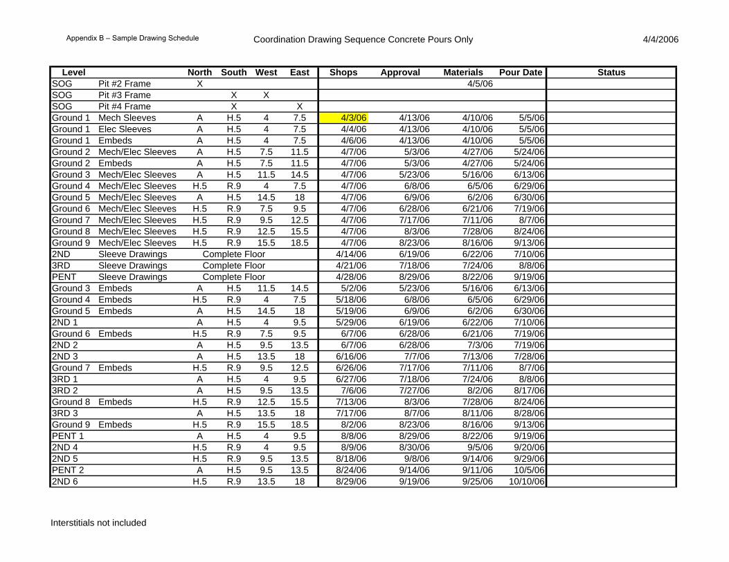
Coordination Drawing Sequence Concrete Pours Only 4/4/2006
Level North South West East Shops Approval Materials Pour Date StatusSOG Pit #2 Frame X 4/5/06SOG Pit #3 Frame X XSOG Pit #4 Frame X XGround 1 Mech Sleeves A H.5 4 7.5 4/3/06 4/13/06 4/10/06 5/5/06Ground 1 Elec Sleeves A H.5 4 7.5 4/4/06 4/13/06 4/10/06 5/5/06Ground 1 Embeds A H.5 4 7.5 4/6/06 4/13/06 4/10/06 5/5/06Ground 2 Mech/Elec Sleeves A H.5 7.5 11.5 4/7/06 5/3/06 4/27/06 5/24/06Ground 2 Embeds A H.5 7.5 11.5 4/7/06 5/3/06 4/27/06 5/24/06Ground 3 Mech/Elec Sleeves A H.5 11.5 14.5 4/7/06 5/23/06 5/16/06 6/13/06Ground 4 Mech/Elec Sleeves H.5 R.9 4 7.5 4/7/06 6/8/06 6/5/06 6/29/06Ground 5 Mech/Elec Sleeves A H.5 14.5 18 4/7/06 6/9/06 6/2/06 6/30/06Ground 6 Mech/Elec Sleeves H.5 R.9 7.5 9.5 4/7/06 6/28/06 6/21/06 7/19/06Ground 7 Mech/Elec Sleeves H.5 R.9 9.5 12.5 4/7/06 7/17/06 7/11/06 8/7/06Ground 8 Mech/Elec Sleeves H.5 R.9 12.5 15.5 4/7/06 8/3/06 7/28/06 8/24/06Ground 9 Mech/Elec Sleeves H.5 R.9 15.5 18.5 4/7/06 8/23/06 8/16/06 9/13/062ND Sleeve Drawings Complete Floor 4/14/06 6/19/06 6/22/06 7/10/063RD Sleeve Drawings Complete Floor 4/21/06 7/18/06 7/24/06 8/8/06PENT Sleeve Drawings Complete Floor 4/28/06 8/29/06 8/22/06 9/19/06Ground 3 Embeds A H.5 11.5 14.5 5/2/06 5/23/06 5/16/06 6/13/06Ground 4 Embeds H.5 R.9 4 7.5 5/18/06 6/8/06 6/5/06 6/29/06Ground 5 Embeds A H.5 14.5 18 5/19/06 6/9/06 6/2/06 6/30/062ND 1 A H.5 4 9.5 5/29/06 6/19/06 6/22/06 7/10/06Ground 6 Embeds H.5 R.9 7.5 9.5 6/7/06 6/28/06 6/21/06 7/19/062ND 2 A H.5 9.5 13.5 6/7/06 6/28/06 7/3/06 7/19/062ND 3 A H.5 13.5 18 6/16/06 7/7/06 7/13/06 7/28/06Ground 7 Embeds H.5 R.9 9.5 12.5 6/26/06 7/17/06 7/11/06 8/7/063RD 1 A H.5 4 9.5 6/27/06 7/18/06 7/24/06 8/8/063RD 2 A H.5 9.5 13.5 7/6/06 7/27/06 8/2/06 8/17/06Ground 8 Embeds H.5 R.9 12.5 15.5 7/13/06 8/3/06 7/28/06 8/24/063RD 3 A H.5 13.5 18 7/17/06 8/7/06 8/11/06 8/28/06Ground 9 Embeds H.5 R.9 15.5 18.5 8/2/06 8/23/06 8/16/06 9/13/06PENT 1 A H.5 4 9.5 8/8/06 8/29/06 8/22/06 9/19/062ND 4 H.5 R.9 4 9.5 8/9/06 8/30/06 9/5/06 9/20/062ND 5 H.5 R.9 9.5 13.5 8/18/06 9/8/06 9/14/06 9/29/06PENT 2 A H.5 9.5 13.5 8/24/06 9/14/06 9/11/06 10/5/062ND 6 H.5 R.9 13.5 18 8/29/06 9/19/06 9/25/06 10/10/06
Interstitials not included
Appendix B – Sample Drawing Schedule

Coordination Drawing Sequence Concrete Pours Only 4/4/2006
Level North South West East Shops Approval Materials Pour Date Status3RD 4 H.5 R.9 4 9.5 9/7/06 9/28/06 10/4/06 10/19/06PENT 3 A H.5 13.5 18 9/11/06 10/2/06 9/27/06 10/23/063RD 5 H.5 R.9 9.5 13.5 9/18/06 10/9/06 10/13/06 10/30/063RD6 H.5 R.9 13.5 18 9/27/06 10/18/06 10/24/06 11/8/06PENT 4 H.5 R.9 4 9.5 10/19/06 11/9/06 11/2/06 11/30/06PENT 5 H.5 R.9 9.5 13.5 11/6/06 11/27/06 11/21/06 12/18/06PENT 6 H.5 R.9 13.5 18 11/16/06 12/7/06 11/21/06 12/28/06
Interstitials not included
Appendix B – Sample Drawing Schedule

51
Appendix C – Sample Meeting Minutes
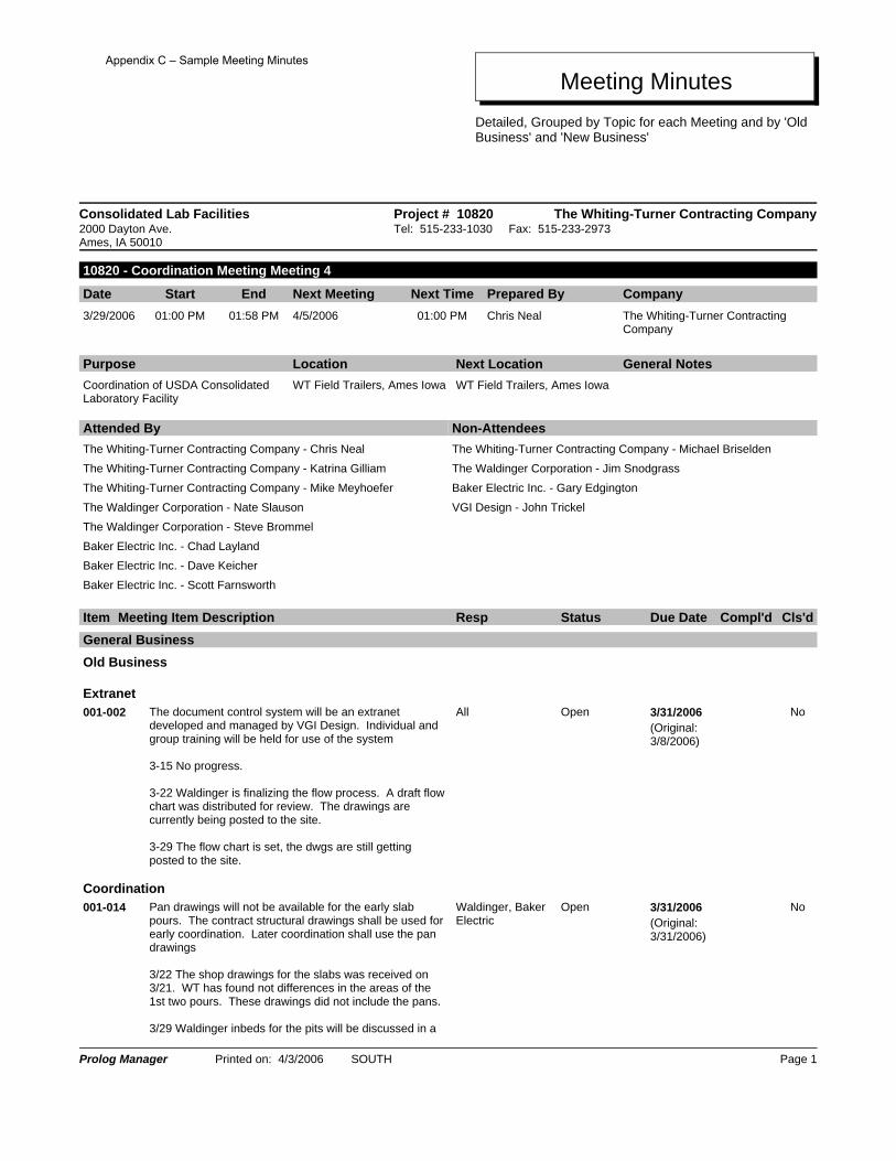
Meeting MinutesDetailed, Grouped by Topic for each Meeting and by 'Old Business' and 'New Business'
Consolidated Lab Facilities The Whiting-Turner Contracting CompanyProject # 108202000 Dayton Ave. Ames, IA 50010
Tel: 515-233-1030 Fax: 515-233-2973
10820 - Coordination Meeting Meeting 4
Date Start End Next Meeting Next Time Prepared By Company3/29/2006 01:00 PM 01:58 PM 4/5/2006 01:00 PM Chris Neal The Whiting-Turner Contracting
Company
Purpose Location General NotesNext LocationCoordination of USDA Consolidated Laboratory Facility
WT Field Trailers, Ames Iowa WT Field Trailers, Ames Iowa
Non-AttendeesThe Whiting-Turner Contracting Company - Michael BriseldenThe Waldinger Corporation - Jim SnodgrassBaker Electric Inc. - Gary EdgingtonVGI Design - John Trickel
Attended ByThe Whiting-Turner Contracting Company - Chris NealThe Whiting-Turner Contracting Company - Katrina GilliamThe Whiting-Turner Contracting Company - Mike MeyhoeferThe Waldinger Corporation - Nate SlausonThe Waldinger Corporation - Steve BrommelBaker Electric Inc. - Chad LaylandBaker Electric Inc. - Dave KeicherBaker Electric Inc. - Scott Farnsworth
Cls'dCompl'dDue DateStatusRespMeeting Item DescriptionItemGeneral BusinessOld Business
ExtranetNo3/31/2006OpenAllThe document control system will be an extranet
developed and managed by VGI Design. Individual and group training will be held for use of the system
3-15 No progress.
3-22 Waldinger is finalizing the flow process. A draft flow chart was distributed for review. The drawings are currently being posted to the site.
3-29 The flow chart is set, the dwgs are still getting posted to the site.
001-002(Original: 3/8/2006)
CoordinationNo3/31/2006OpenWaldinger, Baker
ElectricPan drawings will not be available for the early slab pours. The contract structural drawings shall be used for early coordination. Later coordination shall use the pan drawings
3/22 The shop drawings for the slabs was received on 3/21. WT has found not differences in the areas of the 1st two pours. These drawings did not include the pans.
3/29 Waldinger inbeds for the pits will be discussed in a
001-014(Original: 3/31/2006)
Prolog Manager Printed on: 4/3/2006 SOUTH Page 1
Appendix C – Sample Meeting Minutes

Meeting MinutesDetailed, Grouped by Topic for each Meeting and by 'Old Business' and 'New Business'
Cls'dCompl'dDue DateStatusRespMeeting Item DescriptionItemseperate meeting.
CoordinationYes3/29/20063/22/2006ClosedWaldinger, WTWaldinger needs clarification on how the shafts will be
built and how the support steel for pipes and duct will be installed. These questions will be carried forward to the 2PM subcontractor meeting.
3/29 This issues were resolved in subcontractor meeting
003-001(Original: 3/22/2006)
Meeting ScheduleYes3/27/20063/27/2006ClosedWaldinger, Baker EThe first working meeing will be Monday 3/27 at
Waldinger's shop in Des Moines. The zones for the shafts will be discussed. Following the shafts shall be the inbed layout.
3/29 The working meeting was held and very productive. The basement problem areas were reviewed. Zones were set.
003-002(Original: 3/27/2006)
Meeting ScheduleYes3/29/20063/22/2006RecordAll10 minutes of future coordination meetings will be
allocated to discuss commissioning. Eventually commissioning shall split into it's own series of meetings.
003-003(Original: 3/22/2006)
CoordinationNo3/22/2006RecordAllIn the lab areas, the AL drawings shall be the basis for
coordination. These drawings are the ones the USDA will reveiw for layout. Items shown on E, H, or P drawings not on the AL drawings will be identified.
003-004(Original: 3/22/2006)
CoordinationNo4/5/2006OpenBaker EPanel information from Square D is expected 3/31. Once
received panel size information shall be forwarded to all contractors. All contractors are to avoid passing directly overtop or below the panels.
3/29 Panel information was received from Sq D. This information will be forwarded to Waldinger. The clearance above panels shall be reviewed. Prior to asking for a variance, all other options shall be exhausted.
003-005(Original: 4/5/2006)
CoordinationNo3/27/2006OpenBaker E, WaldingerThe top of the shaft coordination shall dictate how service
enter the bottom of the shaft. This is the priority ofr coordination this week. It will be reviewed at a seperate meeting.
3/29 - Top of shafts have not been reviewed. Waldinger verified Baker Elec space requirements fit the space.
003-006(Original: 3/27/2006)
CoordinationNo3/29/20063/22/2006RecordAllDrives shall be located as close to the equipment they
serve as possible. 003-007
(Original: 3/22/2006)
CoordinationNo3/22/2006RecordAllAll block outs will be shown on a drawing with
dimensions. This information must be given to the structural contractor prior to installation.
003-008(Original: 3/22/2006)
Prolog Manager Printed on: 4/3/2006 SOUTH Page 2
Appendix C – Sample Meeting Minutes

Meeting MinutesDetailed, Grouped by Topic for each Meeting and by 'Old Business' and 'New Business'
Cls'dCompl'dDue DateStatusRespMeeting Item DescriptionItem3/26 sleeve penetrations must also be shown. Drawings for first pour due 4/3.
New Business
CoordinationNo3/29/2006RecordAllCombinations racks are most likely the only option for the
penthouse. Coordination in this area will be based on this assumption.
004-001(Original: 3/29/2006)
CoordinationNo4/5/2006OpenWaldinger; WTWaldinger has identified areas where ductwork risers are
over top of doors. This shall be reviewed and a seperate meeting with WT.
004-002(Original: 4/5/2006)
CoordinationNo3/29/2006OpenWTQuestions about the pans and pan drawings shall be
discussed at the 2PM subprogress meeting. The open items are: Can the pans be drilled or cut? How are inbeds installed? Are there other installation details that must be followed?
004-003(Original: 3/29/2006)
CoordinationNo4/5/2006OpenWaldinger, BakerWT has requested a list of coordination drawings
packages that shall be submitted. This list should be the groups of drawings, not idividual sheets.
004-004(Original: 4/5/2006)
CoordinationYes3/29/2006ClosedWaldingerWaldinger can not support Bakere Conc.'s request to
relocate the recessed walls in the sheer walls. The move would conflict with the carriers.
004-005(Original: 3/29/2006)
Temporary PowerNo4/5/2006OpenBaker E, Baker CBaker E will meet with Baker C to coordinate the power
for the cranes. Open topics are disconnects, lights, recepticles. Baker E also needs more information from Maxim Cranes to verify calcs.
004-006(Original: 4/5/2006)
Cc: Company Name Contact Name Copies Notes
This represents the notes as documented during the meeting by WT. Any modifications, additions, or corrections should be forwarded to the author immediately. These meeting minutes will become part of the Project Files.
Prolog Manager Printed on: 4/3/2006 SOUTH Page 3
Appendix C – Sample Meeting Minutes

55
Appendix D – Extranet Site Screen Shots

Extranet Base Webpage
Appendix D – Extranet Site Screen Shots

Extranet Desktop
Appendix D – Extranet Site Screen Shots

Extranet File List ‐ Sample
Appendix D – Extranet Site Screen Shots

59
Appendix E – Commissioning Plan Extranet Training / Instructions

Appendix E – Commissioning Plan Extranet Training / Instructions
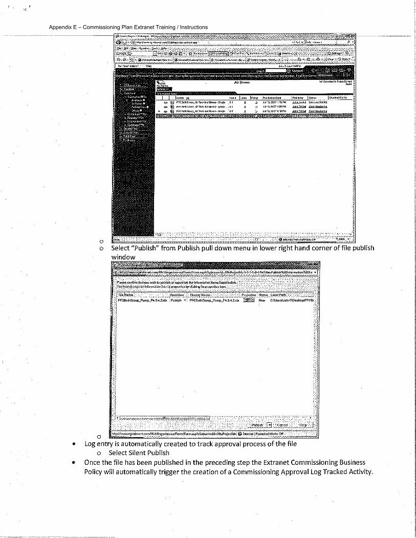
Appendix E – Commissioning Plan Extranet Training / Instructions
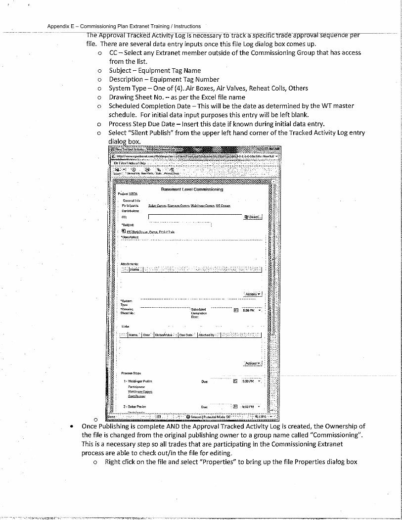
Appendix E – Commissioning Plan Extranet Training / Instructions

Appendix E – Commissioning Plan Extranet Training / Instructions

Appendix E – Commissioning Plan Extranet Training / Instructions

Appendix E – Commissioning Plan Extranet Training / Instructions

Appendix E – Commissioning Plan Extranet Training / Instructions

Appendix E – Commissioning Plan Extranet Training / Instructions

Appendix E – Commissioning Plan Extranet Training / Instructions

Appendix E – Commissioning Plan Extranet Training / Instructions

Appendix E – Commissioning Plan Extranet Training / Instructions

Appendix E – Commissioning Plan Extranet Training / Instructions

Appendix E – Commissioning Plan Extranet Training / Instructions

Appendix E – Commissioning Plan Extranet Training / Instructions

Appendix E – Commissioning Plan Extranet Training / Instructions

Appendix E – Commissioning Plan Extranet Training / Instructions

Appendix E – Commissioning Plan Extranet Training / Instructions

Appendix E – Commissioning Plan Extranet Training / Instructions

Appendix E – Commissioning Plan Extranet Training / Instructions

Appendix E – Commissioning Plan Extranet Training / Instructions