Electron Beam Curing - RadTech · 2014-07-17 · Electron Beam Curing ture of Coil Coatings A...
7
SEPTEMBER/OCTOBER 2003 RADTECH REPORT 47 Feature Electron Beam Curing of Coil Coatings A substantial number of common indoor metal items, such as the back-pieces of lighting fixtures, appliance interiors and exteriors, as well as metals used outdoors, as building siding and roofing, are first coated as flat stock provided in coils and then formed and cut into the desired articles of commerce. Many metal articles are not coated or painted as used or when assembled, but are made from factory coated flat or coiled stock. The National Coil Coating Association (NCCA) provides an extensive amount of information on this process and on market and product uses on its Web site www.coilcoating.org. The use of precoated metals shifts the burden of air quality compliance from the fabricator of metal products to the coil coater. This air quality burden and the recently promulgated Environmental By Anthony J. Berejka Protection Agency’s Maximum Achiev- able Control Technology (MACT) standards have lead some coil coaters to consider electron beam (EB) curing. Why EB curing? EB is known for its ability to penetrate materials and in the case of coatings penetrate down to the substrate irrespective of pigment color or loading. EB is, in a sense, color-blind in that it can deal with any color, even metallics, and achieve durable coated products. EB is also a successful process when dealing with high-volume through- put on a continuous basis. These advantages are being recognized by coil coaters. In addition, EB provides a way for coil coaters to manage the energy requirements of their coating operations while at the same time reducing potential greenhouse gas emissions. ASTM International (www.astm.org) Committee D01 on Paint and Related Coatings, Materials, and Applications has a subcommittee, D01.53, on Coil Coated Metal that addresses the specific test requirements for coil coatings. In particular, ASTM D3794-00 Standard Guide for Testing Coil Coatings, developed in cooperation with the NCCA, catalogs the numerous tests that are applicable to precoated metals. EB Curing of Metal Coatings The use of EB curing of coatings and laminates on metals has been well established. 1 This commercial imple- mentation of EB curing relied upon the curing of discrete pieces of coated steel using a low-voltage EB unit with an extended flat-bed conveyor and shielding zone (Figure 1). In the low- voltage EB-curing community, all pilot Figure 1 EB pilot line at the Japan Atomic Energy Research Institute (JAERI) in Takasaki used for curing coatings on metals
Transcript of Electron Beam Curing - RadTech · 2014-07-17 · Electron Beam Curing ture of Coil Coatings A...
SEPTEMBER/OCTOBER 2003 RADTECH REPORT 47
Feat
ureElectron Beam Curing
of Coil CoatingsA substantial number of
common indoor metal items,
such as the back-pieces of
lighting fixtures, appliance interiors and
exteriors, as well as metals used
outdoors, as building siding and roofing,
are first coated as flat stock provided in
coils and then formed and cut into the
desired articles of commerce. Many
metal articles are not coated or painted
as used or when assembled, but are
made from factory coated flat or coiled
stock. The National Coil Coating
Association (NCCA) provides an
extensive amount of information on this
process and on market and product uses
on its Web site www.coilcoating.org.
The use of precoated metals shifts the
burden of air quality compliance from
the fabricator of metal products to the
coil coater.
This air quality burden and the
recently promulgated Environmental
By Anthony J. Berejka Protection Agency’s Maximum Achiev-
able Control Technology (MACT)
standards have lead some coil coaters to
consider electron beam (EB) curing.
Why EB curing? EB is known for its
ability to penetrate materials and in the
case of coatings penetrate down to the
substrate irrespective of pigment color
or loading. EB is, in a sense, color-blind
in that it can deal with any color, even
metallics, and achieve durable coated
products. EB is also a successful process
when dealing with high-volume through-
put on a continuous basis. These
advantages are being recognized by coil
coaters. In addition, EB provides a way
for coil coaters to manage the energy
requirements of their coating operations
while at the same time reducing
potential greenhouse gas emissions.
ASTM International (www.astm.org)
Committee D01 on Paint and Related
Coatings, Materials, and Applications
has a subcommittee, D01.53, on Coil
Coated Metal that addresses the
specific test requirements for coil
coatings. In particular, ASTM D3794-00
Standard Guide for Testing Coil
Coatings, developed in cooperation with
the NCCA, catalogs the numerous tests
that are applicable to precoated metals.
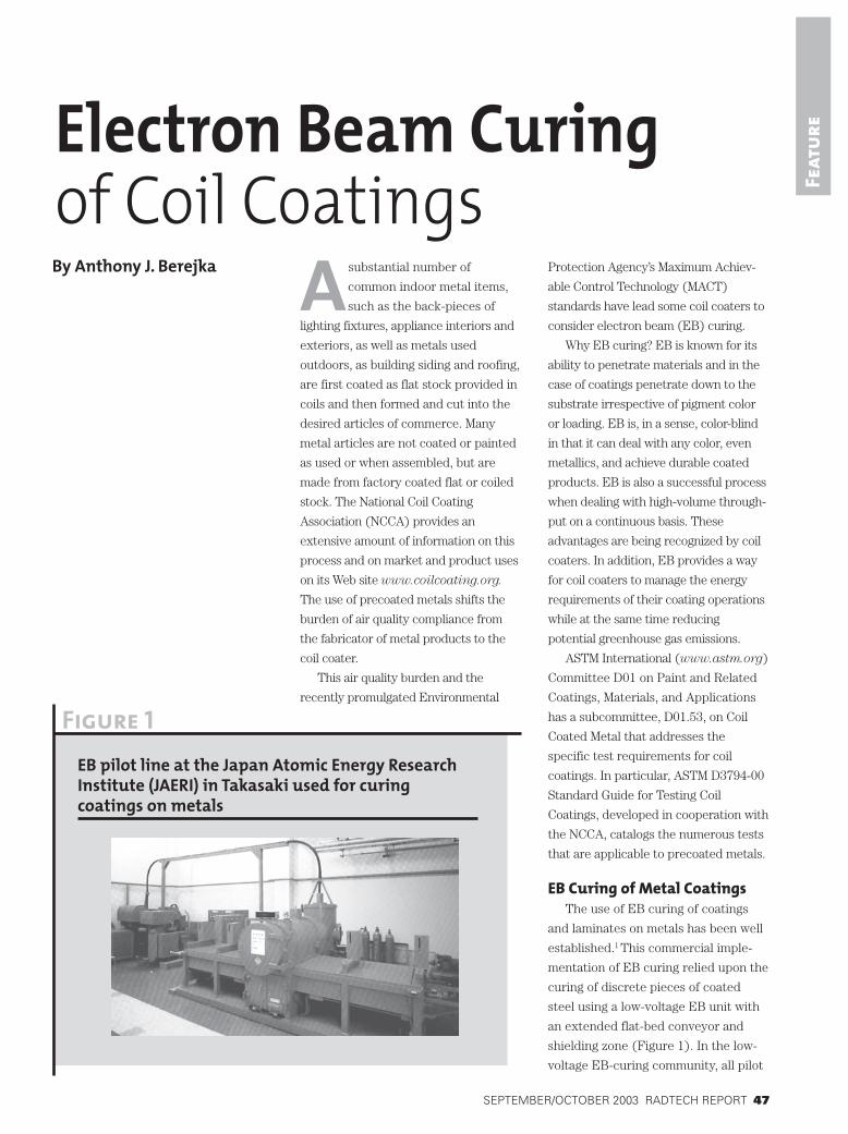
EB Curing of Metal CoatingsThe use of EB curing of coatings
and laminates on metals has been well
established.1 This commercial imple-
mentation of EB curing relied upon the
curing of discrete pieces of coated
steel using a low-voltage EB unit with
an extended flat-bed conveyor and
shielding zone (Figure 1). In the low-
voltage EB-curing community, all pilot
Figure 1
EB pilot line at the Japan Atomic Energy ResearchInstitute (JAERI) in Takasaki used for curingcoatings on metals

48 RADTECH REPORT SEPTEMBER/OCTOBER 2003
Feat
ure
lines are set-up for use with very
flexible, thin gauged materials, such as
papers and films. None can accommo-
date the stiffness of coiled metals, even
a more ductile metal as aluminum. None
have the large diameter coating rolls
used in coil coating operations (see for
example, www.gen-world.com) that are
needed to accommodate metal stiffness
and inflexibility. As a result, judgments
as to the suitability of EB-curable
coatings on metal coil are based on test
panels (Figure 2) and not yet on coil
coated under actual factory conditions.
The development of lower cost, lower
voltage EB units2 and of modular EB
systems3,4 indicate that existing coil
coating lines may be retrofitted with
these more compact units in order for
coil coaters to avail themselves of the
advantages of EB curing.
Technical ChallengesCoil coatings must have excellent
adhesion to metals (ASTM D-3359)
and are required to maintain that
adhesion while meeting the stringent
demands of retaining and enhancing
corrosion resistance, as determined in
salt spray (ASTM B-117, Figure 3) and
other exposure tests. Coil coatings
must also meet the oft-conflicting
requirements for surface hardness
(ASTM D-3363) and for flexibility as
demonstrated by having impact
resistance (ASTM D-2794) and the
ability to be bent or deformed as a
cured coating (ASTM D-522 and
ASTM D-4145, Figures 4, 5 and 6). To
attain these properties, while formulat-
ing at the near-zero VOC (volatile
organic compounds) levels of EB
coatings, presents a formidable
challenge.5 One is often constrained by
the trade-offs between lowering
molecular weight and achieving a
desired lower coating viscosity with
the need for a substantive molecular
weight between crosslinks (Mc) in
order to attain the required cured
coating flexibility and impact resis-
tance.6 Coating systems based on
bimodal molecular weight distributions
of oligomers and monomers that result
in interpenetrating polymer networks
may offer a formulating route for
overcoming these dichotomies. It is
known that the presence of an elastic
component in a polymer matrix will
thwart crack propagation and thus
enhance impact resistance. Likewise,
the adroit use of modified fillers, such
as silane coupled fine particle silicas7 or
acrylate modified inorganic fillers,8 have
long been known to impart toughness
and enhance surface hardness in
polymeric systems. The reemergence of
this technology is gaining fashion as
“nano-particulate technology.”
Figure 2
Laboratory unit showing a diversity of EB-curedcoating colors on metal test panels
Figure 3
1,000 hours saltspray, ASTM B-117

SEPTEMBER/OCTOBER 2003 RADTECH REPORT 49
Feat
ure Figure 4
T-Bend, ASTM D-4145
Figure 5
Mandrel Bend, ASTM D-522
Both free-radical and cationic EB-
curable coating systems are being
explored. Under an inert atmosphere,
free-radical coatings have been shown
to cure onto previously primed thin (0.2
mm) aluminum foil (flexible enough to
make it through a conventional EB pilot
line) at as low as 15 kGy at speeds up to
305 meters per minute. This is well
beyond the current process speeds of
coil coating lines. Test panels, that were
EB cured with pigmented, free-radical
systems deposited at the desired gauge
of 20-microns thickness, have been
found to meet a number of the require-
ments for coil coatings (Figures 3, 4, 5
and 6).
Work is progressing on both free-
radical and cationic-cure systems, the
latter not requiring inerting and
showing the possibility of overcoming
the historic extended propagation step
of cationic curing that would pose
problems in coil coating operations
(potential blocking). This issue of
whether to EB cure a primer coating or
the colored top coating or both is being
discussed as the coatings in develop-
ment for this application demonstrate
enhanced adhesion to metals, as
aluminum, galvanized steel and
Galvalume™, on their own right. The
industry, however, is rightfully con-
Figure 6
Mandrel BentEB c0ating
Figure 7
EB-curable coating wetting Galvalume

50 RADTECH REPORT SEPTEMBER/OCTOBER 2003
Feat
ure
cerned about the long-term corrosion
resistance of any single coat system
and will likely stay with its current
multiple coat operations, including a
metal pretreatment. Assurances of the
viability of single coat systems will
grow as more basic understanding is
gained as to the requirements for a
given coating to adhere and remain
bonded to a specific metal. For
example, using a contact angle
goniometer, it was found that within
an ordered series of EB-curable
coatings, a surface tension of 35
dynes or less was required in order
for this particular type of EB coating
to wet and then adhere to Galvalume
on curing (Figures 7 and 8).9
Environmental ConservationBeyond the ability to comply with
Clean Air Act requirements, that is to
meet the demands for a MACT, EB
curing offers the coil coating industry
added benefits in terms of energy
conservation. If one looks at some
basic information on the evaporation
and drying of solvents and diluents,
like water, and compares it to EB
curing, one finds a remarkable savings
in the energy merely required to dry or
cure a coating (Table 1).10 This
fundamental data does not take into
consideration the heat needed to bring
a metal up to temperature nor the
overall efficiencies of a drying system.
Although energy considerations are
not often included in cost analyses,
this fundamental data complements
the industry’s traditional use of low-
cost solvent-borne polyester systems.
From an energy use perspective, this
illustrates why traditional coatings
have been more often solvent-based,
rather than water-borne. Industry uses
the more energy consumptive water-
borne acrylic coatings for enhanced
Table 1
Energy demands to dry/cure coatings
System Solvent Solvent Water EB Curable
Solids 30% 40% 40% 100%
Diluent heptane toluene water none
Boiling point, °C 98 111 100 NA
Vapor pressure, 20°C 35 mm Hg 22 mm Hg 17 mm Hg NA
Heat of vaporization 76 88 540 NA(calories/gram solvent)
Energy to dry/cure1g dried coating 177 132 810 7(calories/gram solvent) (30 kGy)
Energy to dry/cure1g dried coating, J/g 740 555 3390 30
Figure 8
Surface tension vs. contact angle relationship forEB-curable coatings
33
55
50
45
40
35
30
35 37 39
Surface Tension, dynes
Co
nta
ct A
ng
le

SEPTEMBER/OCTOBER 2003 RADTECH REPORT 51
Feat
ureexterior performance. When compar-
ing the energy demand needed to dry
a water-borne coating, EB curing
would require two orders of magni-
tude less energy to attain comparable
properties. This does not take into
account the thermal inefficiencies of
forced air drying systems. Unlike
thermal convection systems,
EB curing is a direct means of energy
transfer. Energy emitted from an
EB unit is directly absorbed in the
coating and causes the chemical
changes that convert a liquid coating
into a dried and cured material and
does so irrespective of pigment and
pigment loading.
By way of illustration, a coil coating
operation using a 150 cm (60 inches)
wide aluminum stock and running at a
line speed of 125 meters/minute (410
feet/minute) will produce 11,250
square-meters of coated product per
hour (13,455 square-yards/hour). With
a high-solids coating (60% solids)
deposited at a desired 20-microns
(0.8 mils) dried film thickness, ~375
liters of wet coating per hour (100
gallons per hour) of coating would be
consumed, of which ~150 liters would
be VOCs (40 gallons). Assuming a
solvent density of 0.9, this means that
135 kilos (~300 pounds) of VOCs will
have to be dealt with per hour.
Studies of forced air drying and
solvent recovery systems have shown
that it takes ~27.3 kilo-Joules (kJ) of
energy for such forced air systems to
evaporate a gram of solvent.11 For the
135 kilos (135,000 grams) of solvent,
~3,700,000 kJ of energy per hour
(1,030 kilowatt-hours/kWh) would be
needed. If the VOCs are recovered and
then used to fuel the forced air ovens,
there would still be considerable
greenhouse gas emissions. Assuming a
simple solvent having only seven
carbon atoms was used, such as
heptane, the resulting equivalent in
greenhouse gas emissions of just
carbon dioxide (not including nitrous
oxides) from the 135 kilos (300
pounds) of burnt solvent would be
415.8 kilos (917 pounds) per hour of
operation or ~2,500 metric tonnes on
an annualized 6,000 hour production
schedule. (One gram-molecular-weight
or mole of heptane at 100 upon
combustion yields seven moles of
carbon dioxide at 44 grams per mole
for a total of 308 grams of CO2.)
Table 2 presents a summary and
compares these factors with the use of
an energy-efficient EB system that
converts 70% of incoming line power
to usable EB.
Additional energy is required to
heat the metal substrate and varies
with the gauge and type of metal and
also depends upon the specific heat of
a given alloy. In coil coating, further
energy demands are made to remove
the heat from metals. Sometimes cold
water provided through electrically
powered chillers is needed, further
Table 2
Comparison of solvent-based drying with EB curing
System Solvent EB Curable
Coating solids concentration 60% 100%
Dried coat weight, g/m2 20 g 20 g
VOCs/m2, grams (0.9 density solvent) 12 g 0 g
Total force air system energy demand, kJ/m2 328 kJ NA(calculated 27.3 kJ/g to dry)
Total EB energy demand, kJ/m2 NA 0.86 kJ(30 kGy or 0.030 kJ/g at 70%electrical input to effective EB)
Total energy demand/hour ~3,700,000 kJ ~9,600 kJ(11,200 m2/hour production)
Total energy demand/hour 1,030 kWh 2.67 kWh
Greenhouse gas emission potential
CO2 from solvent combustion 37 g/m2 none
Facility CO2 emission potential 415.8 kg/hour none

52 RADTECH REPORT SEPTEMBER/OCTOBER 2003
Feat
ure adding to the overall energy demand.
Obviously, with water-borne systems,
the water vehicle itself cannot be used
as fuel, as in the case of recovered
solvent. This adds additional energy
demands and exacerbates the differ-
ences between water-borne systems
and radiation-curable ones and even
between water-borne systems and the
traditional solvent-borne coil coatings.
Market Barriers to ChangeA good deal of leading-edge
development work targeted at coil
coatings is being conducted by modest-
sized companies (for example, Polyset
and Strathmore Products of New York
and R&D Coatings of Pennsylvania).
Major coil coaters, however, express a
desire to complement these outstand-
ing efforts with continued reliance
upon their more traditional suppliers.
Most of these suppliers have some
capability in the area of radiation-
curable coatings. Nonetheless, they
seem reluctant to displace their
existing business in solvent-borne
technology with radiation-curable
systems. Often, there is even a
disjuncture within a company between
its coil coating division and those
engaged in radiation curables,
something the coil coater finds difficult
to understand.
A major barrier to industry change
is that most coil lines, whether captive
or those of toll service providers, have
been amortized and, within the United
States, sufficient industry capacity is
now in place. Solvent recovery and/or
incineration systems are also in place,
enabling most producers to meet
MACT requirements. Since total
energy costs, including the costs of
operating solvent recovery/incineration
systems, and certainly environmental
costs, such as greenhouse gas emis-
sions, are not part of conventional
product cost analyses, there seems to
be little incentive for the coil industry
to change technologies. Emission control
costs in themselves do not take into
account total energy costs, including
operating costs for thermal drying
systems. Entrepreneurial risk will have
to be assumed if a coil coater is to
embrace what appears in the long term
to be a more profitable route, all cost
factors considered including energy and
the environment, to efficient coil coating,
that is the use of EB curing.12,13
Another barrier to change is that in
many instances the coating is specified
by the coil coater’s own customer,
particularly by those who use toll
coating facilities. Thus, any given
coater maintains hundreds of different
coatings on hand as qualified materials.
Unlike the graphic arts area, wherein
color matching is relied upon and it is
up to the printer to choose his vendor
of choice, in coil coating, the vendor of
the coating is often specified by the
coil coater’s own customer. Nowhere is
this more evident than in the specifica-
tion of coatings based upon
polyvinylidene fluoride (PVdF) in
which even the trademarked brand of
the base resin is specified. PVdF is
known for its outstanding outdoor
weathering properties. Co-polymers of
PVdF, which are presently used in the
solvent-based coatings, can also be
formulated into EB-curable systems.
These EB materials ought to maintain
the same outstanding weathering
properties of PVdF systems, but yet
enable the coil coater to take advantage
of the environmental and energy benefits
of EB curing. PVdF itself has long been
known as a radiation-curable polymer.14
However, it will take a considerable
effort on the part of the manufacturers
of EB-curable coil coatings to demon-
strate the long term outdoor exposure
performance and weatherability
comparable to systems that have been in
use for several decades.
EB curing of coil coatings clearly
represents not only a way to meet the
most stringent MACT standards, but
also a way in which to achieve both
energy efficiency and to reduce, if not
eliminate, greenhouse gas emissions.
At an assumed cost of electricity of
$0.08 per kWh, the annualized (6,000
hour year) savings in energy costs
alone (~$490,000) would enable a coil
coater to expense or depreciate a
suitable EB system within a few years.
For the coil coating industry to adopt
this environmentally benign process
will require present suppliers of coil
coatings to work with the more
innovative smaller companies that have
addressed this market’s needs, to pull
together their own internal resources
on radiation-curable materials, and
commit to obsolescing their present
solvent-based product lines.
Aside from captive coil coating lines
operated by major metals companies,
the coil coater is most often a toll
service provider. The purchaser not
only specifies the metal, but also the
metal pretreatment, the type and color
of the coating and even the coating
brand. As the NCCA points out, a
common challenge to overcome within
the coil coating industry includes
maintaining multiple colors in small
volumes. For an innovative technology
as electron beam processing to
succeed, a change will be needed in
the coil coating marketing paradigm
wherein the coil coater, and not
necessarily the purchaser of coated
coil, becomes the one who primarily
specifies the coatings. This requires a
highly cooperative effort between the
ultimate customer and purchaser of
the coated coil or metal, the coil coater
and the supplier(s) of coil coatings.
This shift in market structure would
also enable coil coaters to greatly
reduce their inventories and lists of
“qualified” coatings down to a more
manageable number. This will provide
a clear benefit to the coil coater’s
customer while providing significant
SEPTEMBER/OCTOBER 2003 RADTECH REPORT 53
Feat
ureenvironmental benefits. By centralizing
coating operations in highly efficient
facilities, coil coaters have already
shifted the burdens of environmental
compliance from the users of coated
metals, the metal fabricators, to
themselves. Implementation of EB
curing would enhance the environmen-
tal compliance of coil coating operations
while providing energy savings and even
reductions in greenhouse gas emissions.
Author’s NoteMore detailed information on
greenhouse gases is provided on the
U.S. Department of Energy’s Energy
Information Agency Web site at
www.eia.doe.gov. ◗
References1. Koshiishi, K., Tomosue, K., Honma, N.,
Sukeda, E., and Masuhara, K. (1990)“Applications of Low Energy ElectronBeam to Precoated Steel,” RadTechReport, May/June 1990, pp. 21-27.
2. Rangwalla, Im and McGuire, Ed. (2002)“Performance Characteristics and NewDevelopment of Low Cost LowVoltage EB Equipment,” RadTech 2002Technical Conference Proceedings, pp.903-911.
3. Felis, Kenneth; Avnery, Tovi; andBerejka, Anthony J. (2002) “InnovativeEnergy Efficient Low Voltage ElectronBeam Emitters,” Radiation Physics andChemistry, 63, nos. 3-6, pp. 605-608.
4. Berejka, Anthony J.; Felis, Tiffany;Felis, Kenneth; and Avnery, Tovi. (2002)“Innovative Electron Beam Emitters,”RadTech 2002 Technical ConferenceProceedings, pp. 919-930.
5. Lowe, C., Watts, J. F., Lavaste, V.,Leadley, S. R., and Rodriguez, A.(1999) “Mission Impossible: GettingRadiation Cured Coatings to Stick toMetal,” RadTech Europe 1999Conference Proceedings, pp. 77-88.
6. Rechel, Camille, editor. (1990)Radiation Curing Primer I — Inks,Coatings and Adhesives, RadTechInternational North America, Bethesda,MD, pp. 39-47.
7. Plueddemann, Edwin. (1973) “CationicSilane Coupling Agents for Thermo-plastics,” Polymer-Plastic Technologyand Engineering, 2(1), pp. 89-106.
8. Kaas, Roger L. and Gardlund, Zack G.(1976) “Surface Modification of Fillersby Radiation Polymerization” GeneralMotors Research Laboratory Publica-tion GMR-2304.
9. Larsen, Scott. (2000) “Electron BeamCured Coatings for Metals,” presentedat the 9th Annual CIRMS Meeting,NIST, Gaithersburg, MD, November2000.
10. Berejka, Anthony J. (1997)“Reengineering PSA Manufacture forVOC Reduction and Energy Savings,”Adhesives Age, July 1997, pp. 30-36.
11. Shell Chemical Company (1979) “AnEconomic Analysis of PressureSensitive Adhesives in SolventSystems” brochure SC148-79,Houston, Texas.
12. Berejka, Anthony J. (1995) “IrradiationProcessing in the 90’s: Energy Savingsand Environmental Benefits” invitedspeaker at the 9th InternationalMeeting on Radiation Processing,Istanbul, Turkey, September, 1994, inRadiation Physics and Chemistry, Vol.46, Nos. 4-6, pp. 429-437.
13. Berejka, Anthony J. (1993) “What’s aWatt Worth? — A Review of the Cost-Effectiveness of Irradiation Process-ing” to the 28th Intersociety EnergyConversion Engineering Conference:Energy + Environment + Economics,Atlanta, GA, August, 1993.
14. Timmerman, Robert. (1964) “Cross-Linking of Polyvinylidene Fluoride andWire Coated with Crosslinked Resin,”US 3,142,629, July 28, 1964.
—Anthony J. Berejka is president
of Ionicorp+, Huntington, N.Y.