
Electromagnetically Driven Fusion Propulsion Driven Fusion Propulsion IEPC 2013 Anthony Pancotti...
45
Electromagnetically Driven Fusion Propulsion IEPC 2013 Anthony Pancotti John Slough, David Kirtley, George Votroubek, Christopher Pihl MSNW LLC, Redmond, WA 98052
-
Upload
phungxuyen -
Category
Documents
-
view
221 -
download
2
Transcript of Electromagnetically Driven Fusion Propulsion Driven Fusion Propulsion IEPC 2013 Anthony Pancotti...
Electromagnetically Driven Fusion Propulsion
IEPC 2013
Anthony Pancotti John Slough, David Kirtley, George Votroubek, Christopher Pihl
MSNW LLC, Redmond, WA 98052
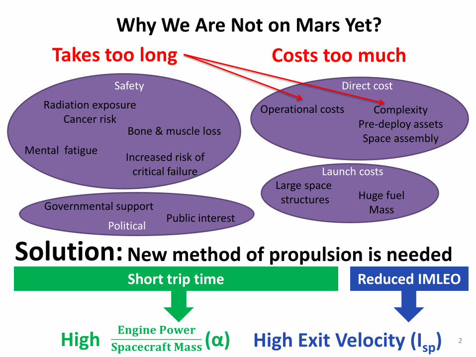
Why We Are Not on Mars Yet?
High Exit Velocity (Isp)
Takes too long
Operational costs Complexity Pre-deploy assets Space assembly
Safety
Radiation exposure Cancer risk
Bone & muscle loss
Mental fatigue Increased risk of critical failure
Governmental support Public interest
Political
High (α)
Costs too much Direct cost
Launch costs Large space structures Huge fuel
Mass
Solution: New method of propulsion is needed Short trip time Reduced IMLEO
2
••
••
••
••
•
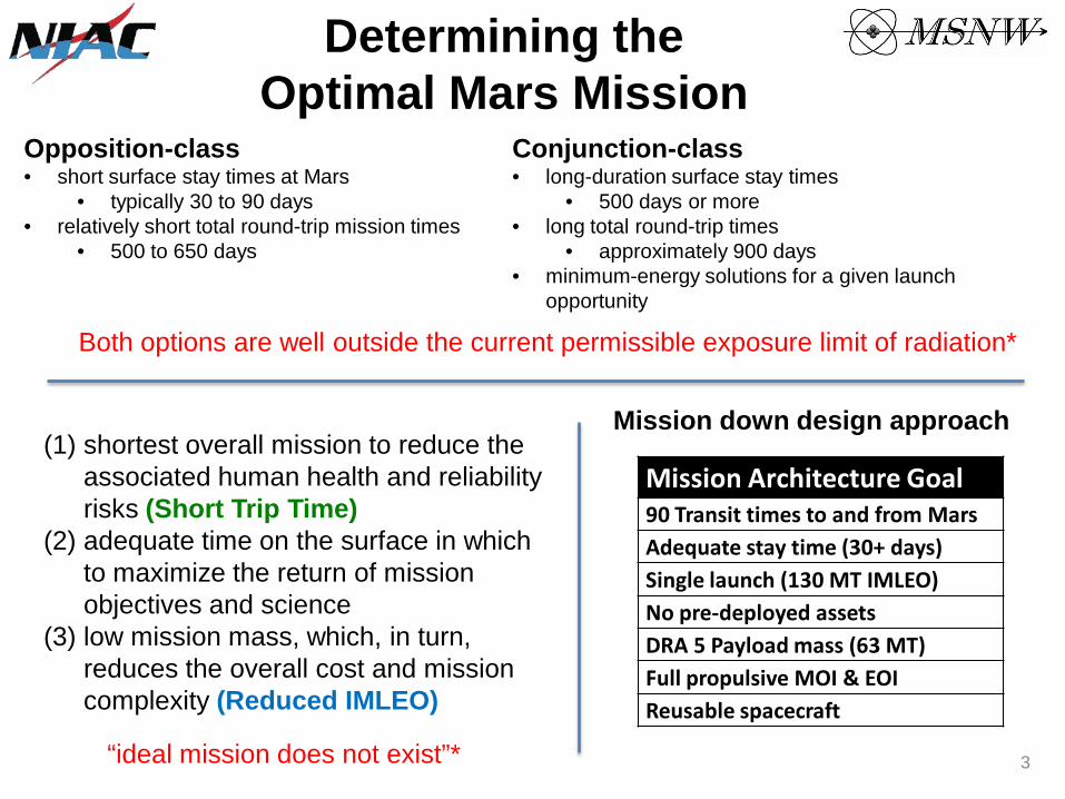
Determining the Optimal Mars Mission
Opposition-class short surface stay times at Mars
typically 30 to 90 days relatively short total round-trip mission times
500 to 650 days
Conjunction-class long-duration surface stay times
500 days or more long total round-trip times
approximately 900 days minimum-energy solutions for a given launch opportunity
Both options are well outside the current permissible exposure limit of radiation*
(1) shortest overall mission to reduce the associated human health and reliability risks (Short Trip Time)
(2) adequate time on the surface in which to maximize the return of mission objectives and science
(3) low mission mass, which, in turn, reduces the overall cost and mission complexity (Reduced IMLEO)
“ideal mission does not exist”*
Mission down design approach
Mission Architecture Goal 90 Transit times to and from Mars Adequate stay time (30+ days) Single launch (130 MT IMLEO) No pre-deployed assets DRA 5 Payload mass (63 MT) Full propulsive MOI & EOI Reusable spacecraft
3
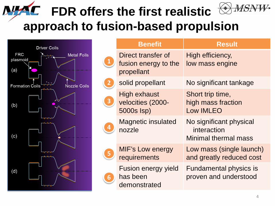
FDR offers the first realistic approach to fusion-based propulsion
Benefit Result
1 Direct transfer of fusion energy to the propellant
High efficiency, low mass engine
2 solid propellant No significant tankage
3 High exhaust velocities (2000- 5000s Isp)
Short trip time, high mass fraction Low IMLEO
4 Magnetic insulated nozzle
No significant physical interaction
Minimal thermal mass
5 MIF’s Low energy requirements
Low mass (single launch) and greatly reduced cost
6 Fusion energy yield has been demonstrated
Fundamental physics is proven and understood
4

210 day Round-trip (COPERNICUS)
Maneuver ΔV (km/s) ΔT (days) Near Body Simplified Near Body Simplified
TMI 12.7 7.3 8.9 7.1 MOI 8.5 13.2 4.7 10.5 TEI 16.6 16.5 1.7 2.9 EOI 11.2 12 1.6 1.6 Total 49.0 49.0 16.8 22.1
5
TMI TEI MOI TOI
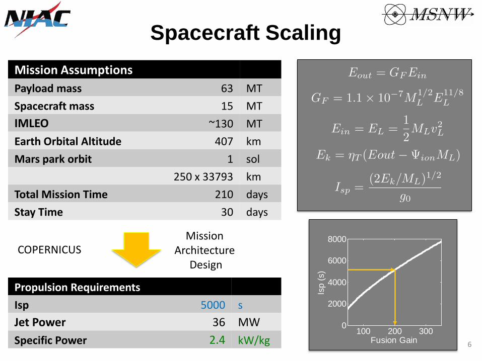
Spacecraft Scaling Mission Assumptions Payload mass Spacecraft mass IMLEO
63 15
~130
MT MT MT
Earth Orbital Altitude 407 km Mars park orbit
1 sol 250 x 33793 km
Total Mission Time Stay Time
210 30
days days
COPERNICUS Mission
Architecture Design
Propulsion Requirements Isp 5000 s Jet Power 36 MW Specific Power 2.4 kW/kg
100 200 3000
2000
4000
6000
8000
Fusion Gain
Isp
(s)
6

Power System Scaling Gain of 200
2.8 MJ Liner Energy at 45% coupling
6.2 MJ of Capacitors @ 2.5 kJ/kg
2.5 MT of Energy Storage
Solar panels have flown on 99% of all space mission. 36 MW Jet Power
Gain of 200 180 kW of Input power OR 400 kW at Mars
200 W/kg
2 MT of Solar Panels 500 W/kg to 1000 W/kg are speculated for the future Direct energy recovery from fusion reaction possible 7
ENER
GY S
TORA
GE
POW
ER S
OU
RCE
Pow
er
Ener
gy
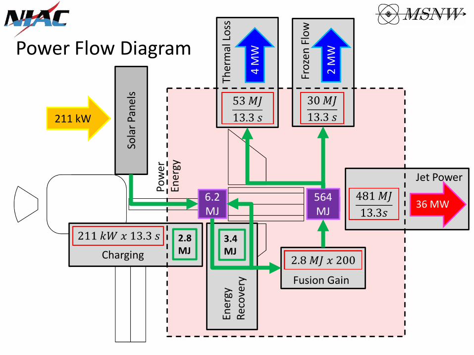
Power Flow Diagram
211 kW
6.2 MJ
Sola
r Pan
els
Ener
gy
Reco
very
3.4 MJ
564 MJ
Froz
en F
low
2 M
W
Ther
mal
Los
s
4 M
W
36 MW
Jet Power
Fusion Gain
Charging 2.8 MJ
Mass Budget
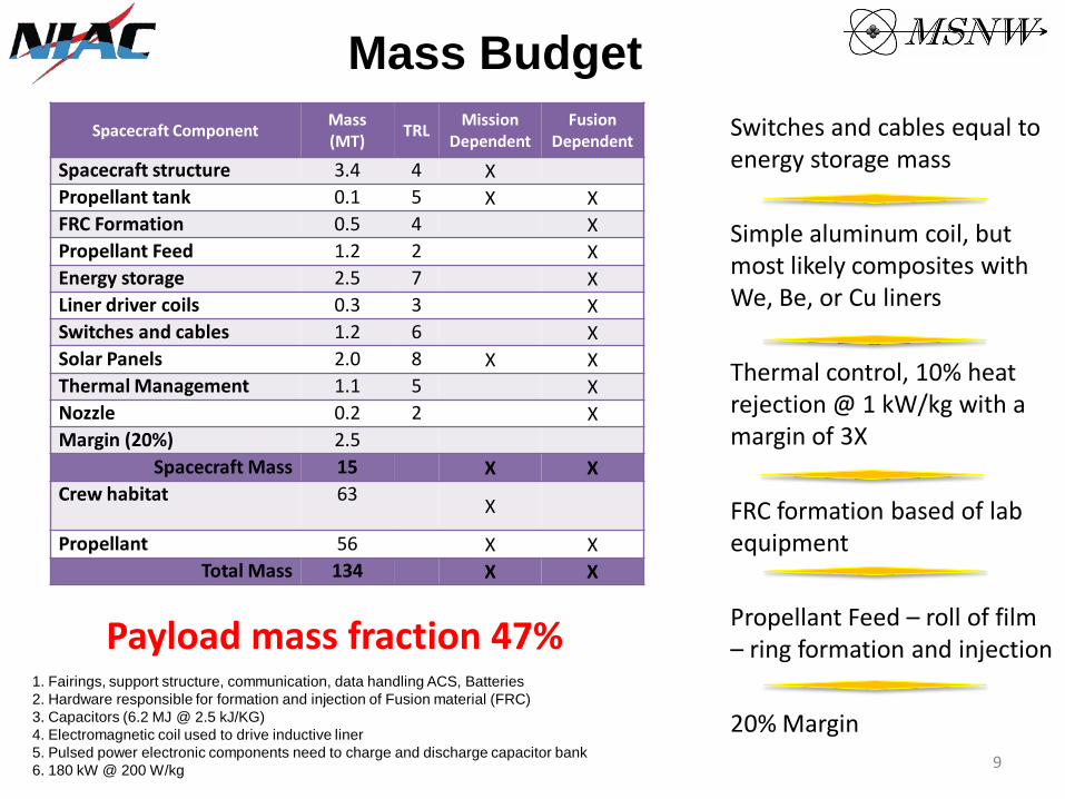
Spacecraft Component Mass (MT) TRL Mission
Dependent Fusion
Dependent Spacecraft structure 3.4 4 X Propellant tank 0.1 5 X X FRC Formation 0.5 4 X Propellant Feed 1.2 2 X Energy storage 2.5 7 X Liner driver coils 0.3 3 X Switches and cables 1.2 6 X Solar Panels 2.0 8 X X Thermal Management 1.1 5 X Nozzle 0.2 2 X Margin (20%) 2.5
Spacecraft Mass 15 X X Crew habitat 63
X
Propellant 56 X X Total Mass 134 X X
Payload mass fraction 47% 1. Fairings, support structure, communication, data handling ACS, Batteries 2. Hardware responsible for formation and injection of Fusion material (FRC) 3. Capacitors (6.2 MJ @ 2.5 kJ/KG) 4. Electromagnetic coil used to drive inductive liner 5. Pulsed power electronic components need to charge and discharge capacitor bank 6. 180 kW @ 200 W/kg
Switches and cables equal to energy storage mass
Simple aluminum coil, but most likely composites with We, Be, or Cu liners
Thermal control, 10% heat rejection @ 1 kW/kg with a margin of 3X
FRC formation based of lab equipment
Propellant Feed – roll of film – ring formation and injection
20% Margin 9
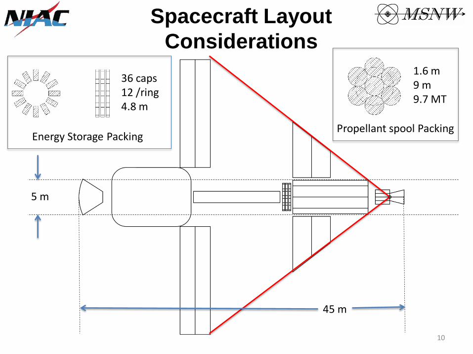
Spacecraft Layout Considerations
Energy Storage Packing Propellant spool Packing
5 m
45 m
10
1.6 m 9 m 9.7 MT
36 caps 12 /ring 4.8 m

210-Day Architecture Summary
Isp = 5000 s α = 2.4 kW/kg
Jet power = 36 MW
Gain = 200 Spacecraft Mass = 15 MT
61 MT payload
83 MT
134 MT
27 MT
15 MT
(May 19, 2018)
Refuel, Re-crew for future missions
FDR 1 launch 134 MT
(IMLEO)
210 days
DRA 5.0 (NTP)
9 launches 848.7 MT
(IMLEO)
1680 days
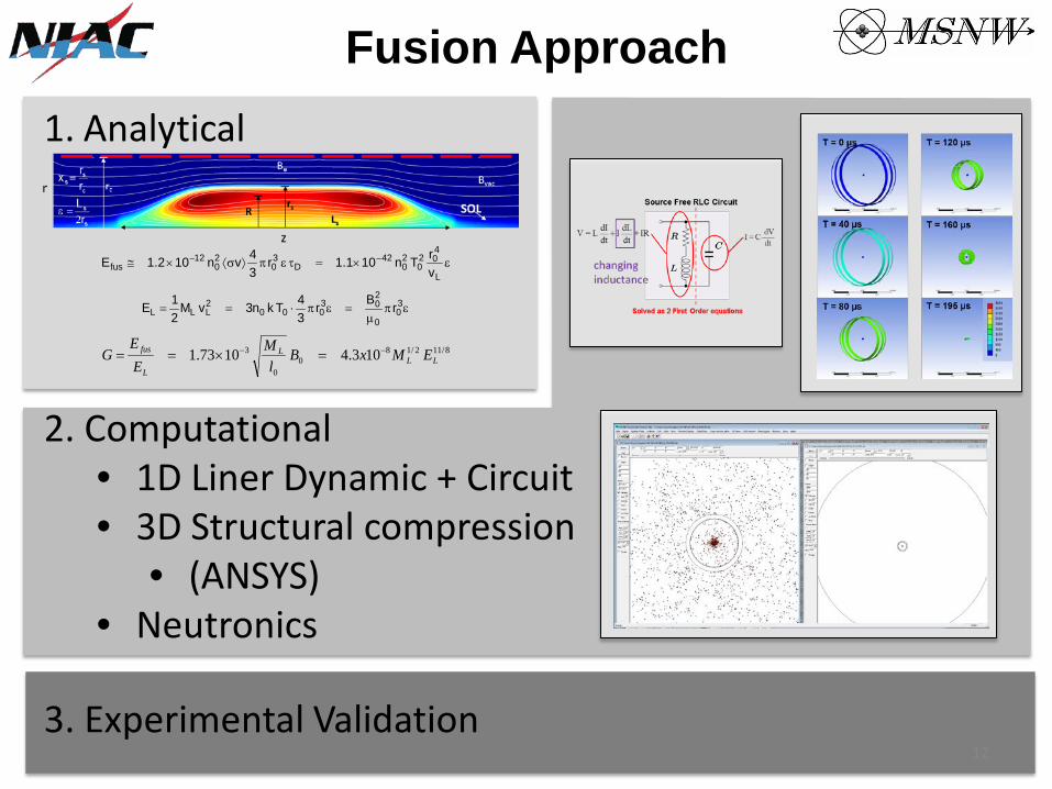
Fusion Approach
••
••
1. Analytical
8/112/180
0
3 103.41073.1 LLL
L
fus EMxBl
MEE
G −− =×==
επµ
=επ⋅== 30
0
203
0002LLL rBr
34Tkn3vM
21E
ε×=τεπ⟩σ⟨×≅ −−
L
402
020
42D
30
20
12fus v
rTn101.1r34vn102.1E
2. Computational 1D Liner Dynamic + Circuit 3D Structural compression
(ANSYS) Neutronics
3. Experimental Validation 12

••
oooo
•
FRC Fusion at MSNW
“Creation of a High Temperature Plasma through Merging and Compression of Supersonic Field Reversed Configuration Plasmoids” . Journal of Nuclear Fusion, 2011
Fusion with this technique is proven $5 M DOE-funded programs demonstrated high field compression of FRC to fusion conditions
2.3 keV Deuterium Ions >100 microsecond lifetimes of 1E22 plasma >1E12 D-D neutrons created in this program At only 1.2 Tesla!
FRC programs at similar size demonstrated >3 ms lifetime 13
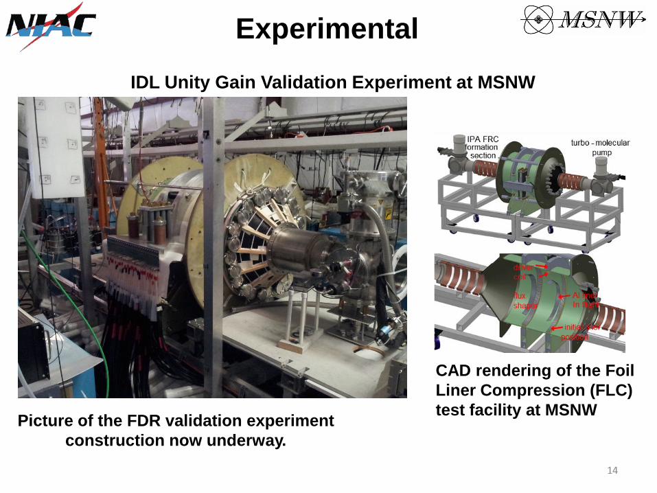
Experimental IDL Unity Gain Validation Experiment at MSNW
Picture of the FDR validation experiment construction now underway.
CAD rendering of the Foil Liner Compression (FLC) test facility at MSNW
14
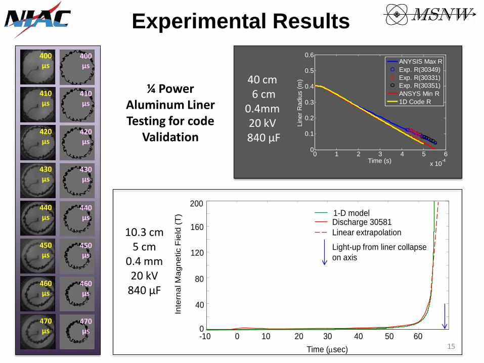
Experimental Results
¼ Power Aluminum Liner Testing for code
Validation
410 μs
400 μs
430 μs
420 μs
450 μs
440 μs
470 μs
460 μs
410 μs
400 μs
430 μs
420 μs
450 μs
440 μs
470 μs
460 μs
0 1 2 3 4 5 6x 10⁻⁴
0
0.1
0.2
0.3
0.4
0.5
0.6
Time (s)
Line
r Rad
ius
(m)
ANYSIS Max RExp. R(30349)Exp. R(30331)Exp. R(30351)ANSYS Min R1D Code R
0
40
80
120
160
200
Time (µsec)
Inte
rnal
Mag
netic
Fie
ld (T
)
Discharge 30581Linear extrapolation
Light-up from liner collapseon axis
1-D model
-10 0 10 20 30 40 50 60
40 cm 6 cm
0.4mm 20 kV
840 μF
10.3 cm 5 cm
0.4 mm 20 kV
840 μF
15
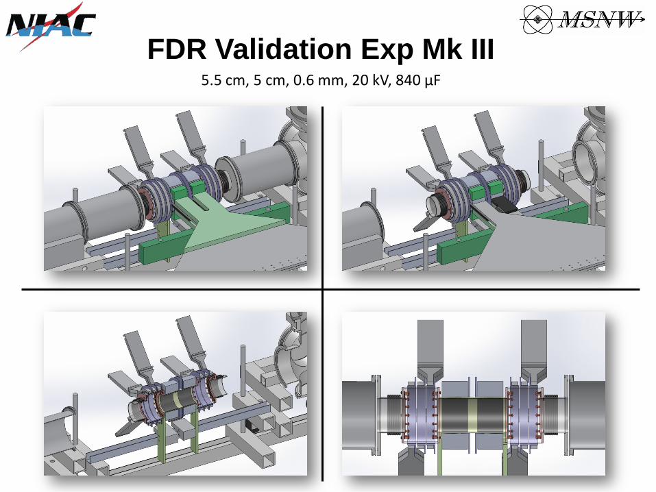
FDR Validation Exp Mk III 5.5 cm, 5 cm, 0.6 mm, 20 kV, 840 μF
Summary
•••
•••
••
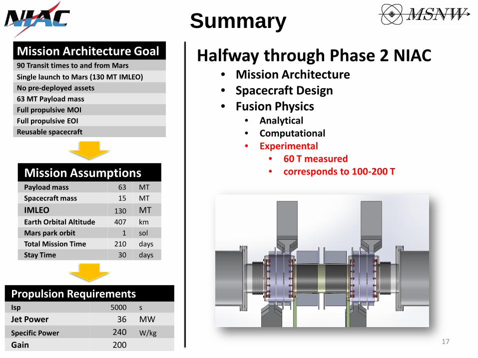
Mission Architecture Goal 90 Transit times to and from Mars Single launch to Mars (130 MT IMLEO) No pre-deployed assets 63 MT Payload mass Full propulsive MOI Full propulsive EOI Reusable spacecraft
Mission Assumptions Payload mass 63 MT Spacecraft mass 15 MT IMLEO 130 MT Earth Orbital Altitude 407 km Mars park orbit 1 sol Total Mission Time 210 days Stay Time 30 days
Propulsion Requirements Isp 5000 s Jet Power 36 MW Specific Power 240 W/kg Gain 200
Halfway through Phase 2 NIAC Mission Architecture Spacecraft Design Fusion Physics
Analytical Computational Experimental
60 T measured corresponds to 100-200 T
17
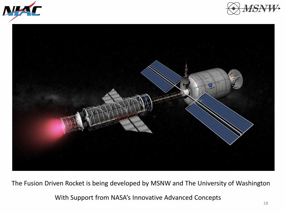
The Fusion Driven Rocket is being developed by MSNW and The University of Washington
With Support from NASA’s Innovative Advanced Concepts 18

BACK-UP SLIDES
19
•
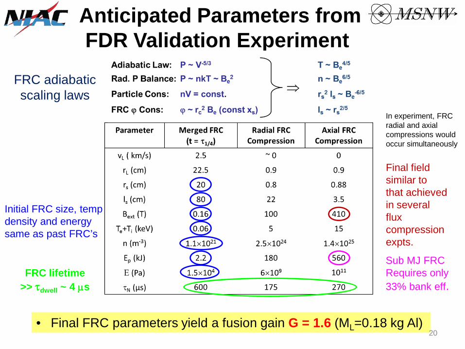
Anticipated Parameters from FDR Validation Experiment
FRC adiabatic scaling laws
Initial FRC size, temp density and energy same as past FRC’s
FRC lifetime >> τdwell ~ 4 µs
In experiment, FRC radial and axial compressions would occur simultaneously
Final field similar to that achieved in several flux compression expts.
Sub MJ FRC Requires only 33% bank eff.
Final FRC parameters yield a fusion gain G = 1.6 (ML=0.18 kg Al) 20
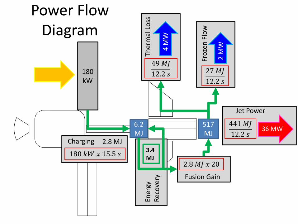
Power Flow Diagram
6.2 MJ
180kW
3.4 MJ
517 MJ
Froz
en F
low
2 M
W
Ther
mal
Los
s
4 M
W
36 MW
Jet Power
Fusion Gain
2.8 MJ Charging En
ergy
Re
cove
ry
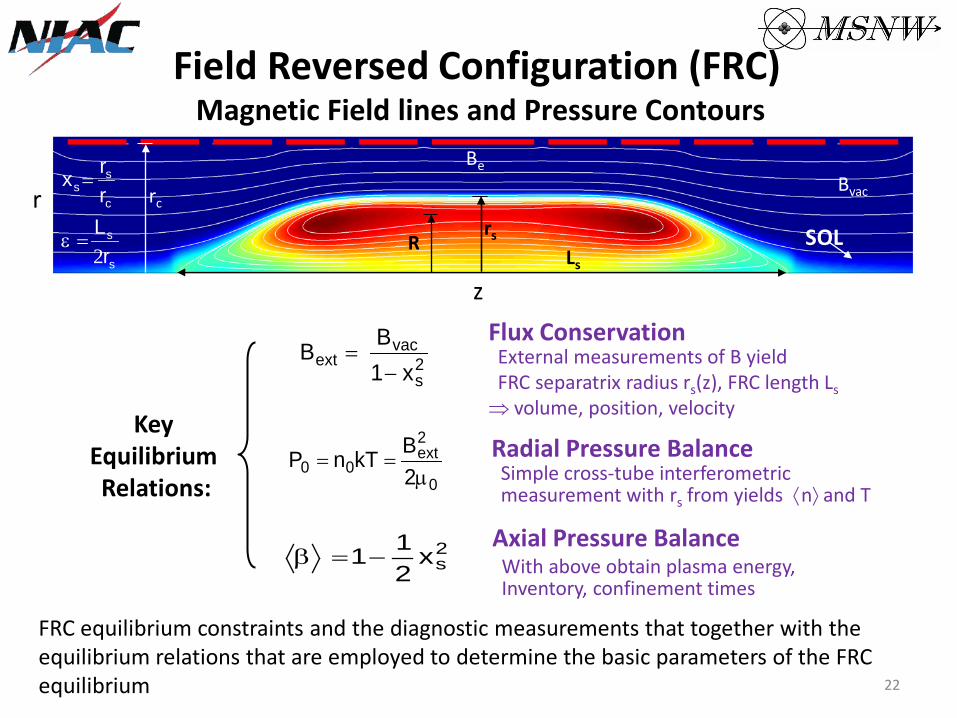
Field Reversed Configuration (FRC) Magnetic Field lines and Pressure Contours
R rs
Ls
rc
Be Bvac r
z s
s
c
ss
rLrrx
2=ε
=
SOL
Key Equilibrium Relations:
2s
vacext x1
BB−
=Flux Conservation External measurements of B yield FRC separatrix radius rs(z), FRC length Ls ⇒ volume, position, velocity
0
2ext
00 2BkTnP
µ== Radial Pressure Balance
Simple cross-tube interferometric measurement with rs from yields ⟨n⟩ and T
2sx
211−=β
Axial Pressure Balance With above obtain plasma energy, Inventory, confinement times
FRC equilibrium constraints and the diagnostic measurements that together with the equilibrium relations that are employed to determine the basic parameters of the FRC equilibrium 22
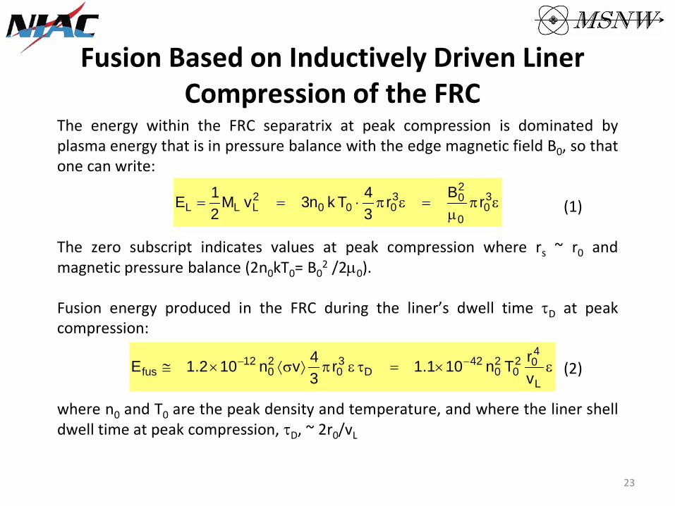
Fusion Based on Inductively Driven Liner Compression of the FRC
The energy within the FRC separatrix at peak compression is dominated by plasma energy that is in pressure balance with the edge magnetic field B0, so that one can write:
επµ
=επ⋅== 30
0
203
0002LLL rBr
34Tkn3vM
21E (1)
The zero subscript indicates values at peak compression where rs ~ r0 and magnetic pressure balance (2n0kT0= B 2
0 /2µ0).
Fusion energy produced in the FRC during the liner’s dwell time τD at peak compression:
ε×=τεπ⟩σ⟨×≅ −−
L
402
020
42D
30
20
12fus v
rTn101.1r34vn102.1E (2)
where n0 and T0 are the peak density and temperature, and where the liner shell dwell time at peak compression, τD, ~ 2r0/vL
23
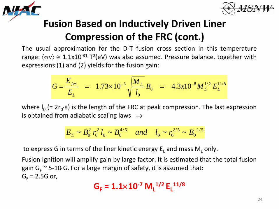
Fusion Based on Inductively Driven Liner Compression of the FRC (cont.)
The usual approximation for the D-T fusion cross section in this temperature range: ⟨σν⟩ ≅ 1.1x10⁻³¹ T2(eV) was also assumed. Pressure balance, together with expressions (1) and (2) yields for the fusion gain:
8/112/18
00
3 103.41073.1 LLL
L
fus EMxBl
MEE
G −− =×==
where l0 (= 2r0⋅ε) is the length of the FRC at peak compression. The last expression is obtained from adiabatic scaling laws ⇒
5/10
5/200
5/400
20
20 ~~~~ −BrlandBlrBEL
to express G in terms of the liner kinetic energy EL and mass ML only. Fusion Ignition will amplify gain by large factor. It is estimated that the total fusion gain GF ~ 5-10⋅G. For a large margin of safety, it is assumed that: GF = 2.5G or,
GF = 1.1×10⁻⁷ ML1/2 EL
11/8 24
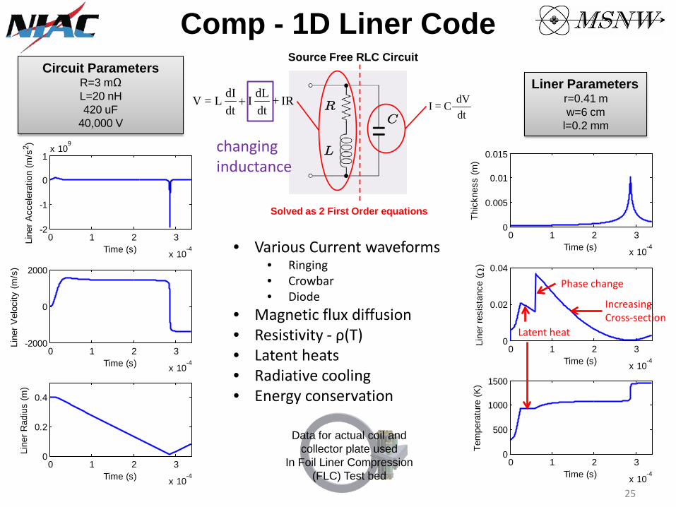
Source Free RLC Circuit
Comp - 1D Liner Code
••••
•••••
Circuit Parameters R=3 mΩ L=20 nH 420 uF
40,000 V
0 1 2 3
x 10-4
-2
-1
0
1x 10
9
Time (s)
Line
r Acc
eler
atio
n (m
/s2 )
0 1 2 3
x 10-4
-2000
0
2000
Time (s)
Line
r Vel
ocity
(m/s
)
0 1 2 3
x 10-4
0
0.2
0.4
Time (s)
Line
r Rad
ius
(m)
IR+dtdL I
dtdI L=V +
changing inductance
dtdV C=I
Solved as 2 First Order equations
Various Current waveforms Ringing Crowbar Diode
Magnetic flux diffusion Resistivity - ρ(T) Latent heats Radiative cooling Energy conservation
Data for actual coil and collector plate used
In Foil Liner Compression (FLC) Test bed
Liner Parameters r=0.41 m w=6 cm
l=0.2 mm
0 1 2 3
x 10-4
0
0.005
0.01
0.015
Time (s)
Thic
knes
s (m
)
0 1 2 3
x 10-4
0
0.02
0.04
Time (s)
Line
r res
ista
nce
( Ω)
0 1 2 3
x 10-4
0
500
1000
1500
Time (s)Te
mpe
ratu
re (K
)
Latent heat
Increasing Cross-section
Phase change
25

ANSYS Explicit Dynamics® Calculations Three 0.4 m radius, 5 cm wide, 0.2 mm thick Aluminum liners converging onto a stationary test target. First 3D structure compression of metallic liner No gross instabilities were observed due to the structure rigidity of the material Forces are well beyond the plastic deformation limit of the material, resulting in a uniform compression Low internal energy from the liner compression which is different from plasma or thick liner compression
T = 0 µs T = 120 µs
T = 80 µs
T = 195 µs
Liner behavior agreed very well with 1D Liner Code 26
T = 40 µs T = 160 µs

FDR Spacecraft Layout
Spline Truss
Liner/Propellant
Fusion Driven Rocket
Radiators
Energy Storage Mars Lander
Transit Habitat
Solar Panels
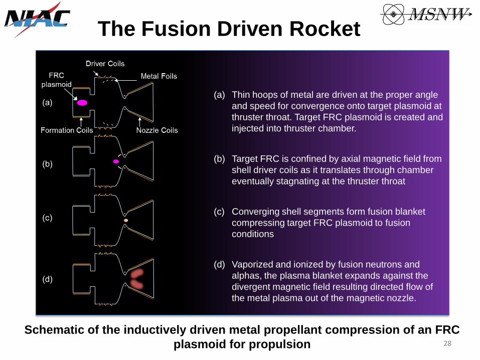
The Fusion Driven Rocket
(a) Thin hoops of metal are driven at the proper angle and speed for convergence onto target plasmoid at thruster throat. Target FRC plasmoid is created and injected into thruster chamber.
(b) Target FRC is confined by axial magnetic field from shell driver coils as it translates through chamber eventually stagnating at the thruster throat
(c) Converging shell segments form fusion blanket compressing target FRC plasmoid to fusion conditions
(d) Vaporized and ionized by fusion neutrons and alphas, the plasma blanket expands against the divergent magnetic field resulting directed flow of the metal plasma out of the magnetic nozzle.
Schematic of the inductively driven metal propellant compression of an FRC plasmoid for propulsion 28
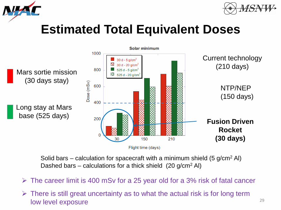
Estimated Total Equivalent Doses
Mars sortie mission (30 days stay)
Long stay at Mars base (525 days)
Current technology (210 days)
NTP/NEP (150 days)
Fusion Driven Rocket
(30 days)
Solid bars – calculation for spacecraft with a minimum shield (5 g/cm2 Al) Dashed bars – calculations for a thick shield (20 g/cm2 Al)
The career limit is 400 mSv for a 25 year old for a 3% risk of fatal cancer
There is still great uncertainty as to what the actual risk is for long term low level exposure 29
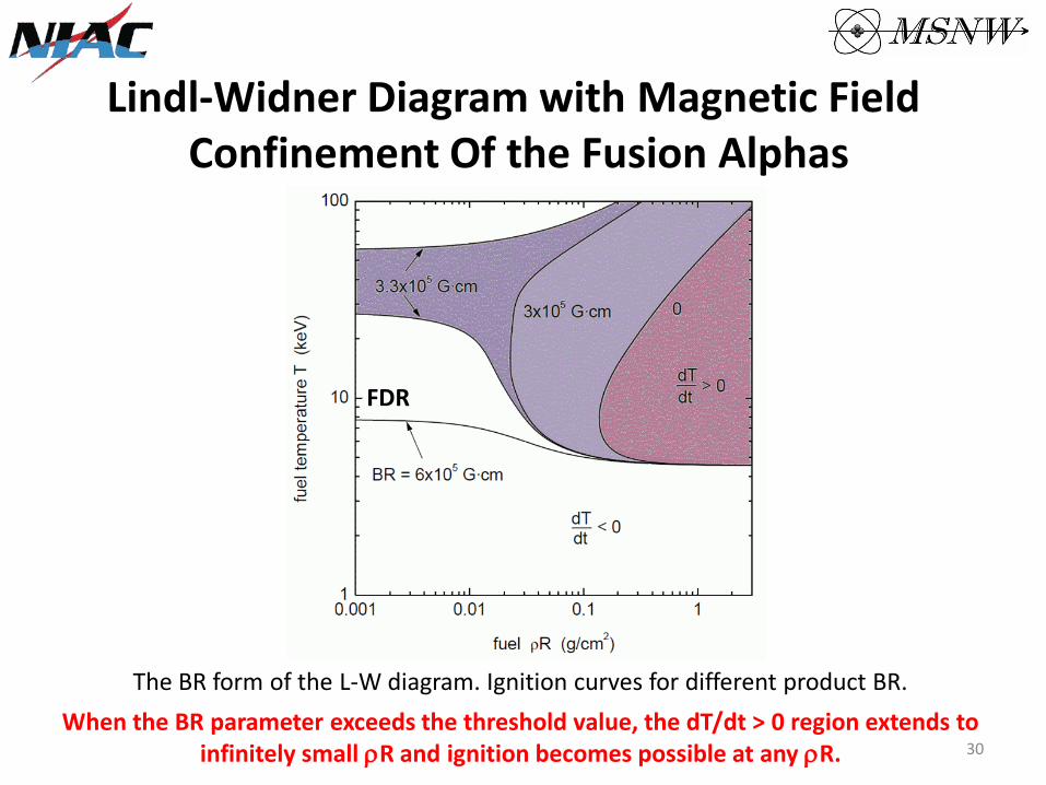
Lindl-Widner Diagram with Magnetic Field Confinement Of the Fusion Alphas
FDR
The BR form of the L-W diagram. Ignition curves for different product BR. When the BR parameter exceeds the threshold value, the dT/dt > 0 region extends to
infinitely small ρR and ignition becomes possible at any ρR. 30
•
•
•
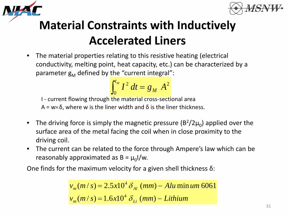
Material Constraints with Inductively Accelerated Liners
The material properties relating to this resistive heating (electrical conductivity, melting point, heat capacity, etc.) can be characterized by a parameter gM defined by the “current integral”:
2
0
2 AgdtI M
tm =∫I - current flowing through the material cross-sectional area A = w×δ, where w is the liner width and δ is the liner thickness.
The driving force is simply the magnetic pressure (B2/2µ0) applied over the surface area of the metal facing the coil when in close proximity to the driving coil. The current can be related to the force through Ampere’s law which can be reasonably approximated as B = µ0I/w.
One finds for the maximum velocity for a given shell thickness δ:
vm (m / s) = 2.5x10⁴ δ Al (mm) − Alu min um 6061
vm (m / s) =1.6x10⁴ δ Li (mm) − Lithium31
••
•
•
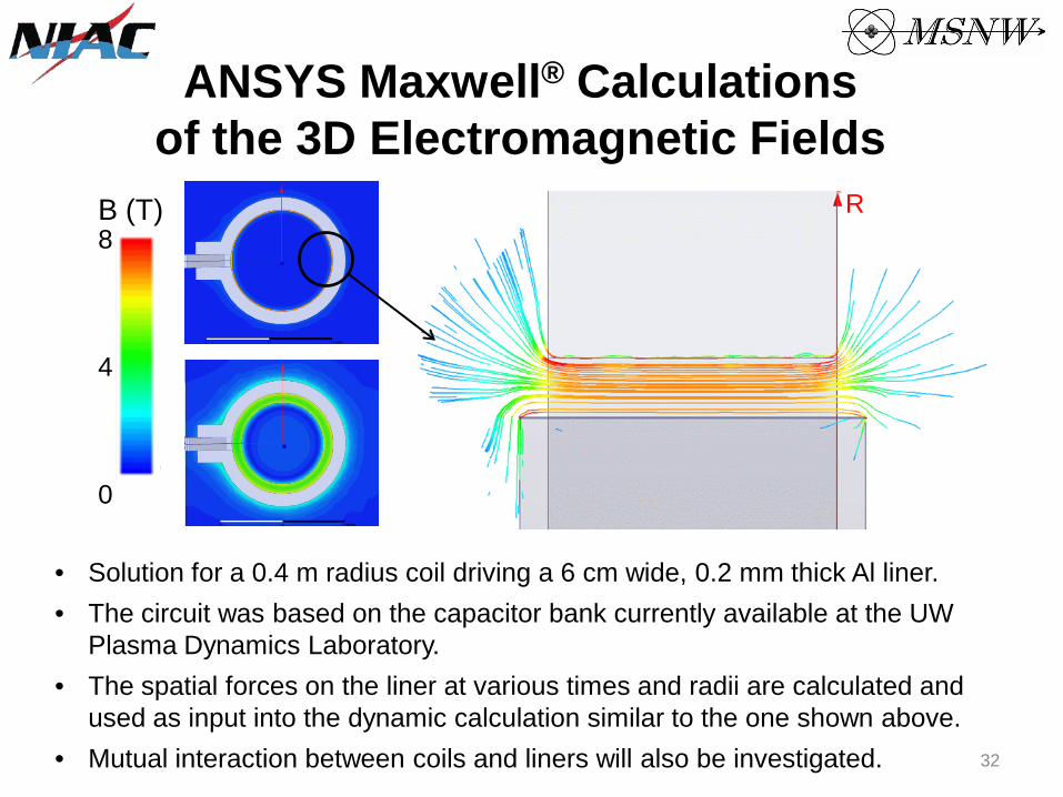
ANSYS Maxwell® Calculations of the 3D Electromagnetic Fields
R B (T) 8 4 0
Solution for a 0.4 m radius coil driving a 6 cm wide, 0.2 mm thick Al liner. The circuit was based on the capacitor bank currently available at the UW Plasma Dynamics Laboratory. The spatial forces on the liner at various times and radii are calculated and used as input into the dynamic calculation similar to the one shown above. Mutual interaction between coils and liners will also be investigated. 32
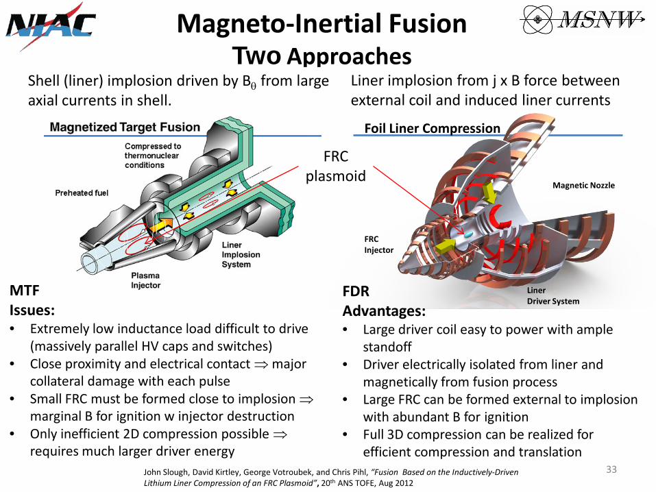
Magneto-Inertial Fusion Two Approaches
Shell (liner) implosion driven by Bθ from large axial currents in shell.
MTF Issues: • Extremely low inductance load difficult to drive
(massively parallel HV caps and switches) Close proximity and electrical contact ⇒ major collateral damage with each pulse Small FRC must be formed close to implosion ⇒ marginal B for ignition w injector destruction Only inefficient 2D compression possible ⇒ requires much larger driver energy
•
•
•
Liner implosion from j x B force between external coil and induced liner currents
•
•
•
•
FRC plasmoid
Foil Liner Compression
Magnetic Nozzle
Liner Driver System
FRC Injector
FDR Advantages:
Large driver coil easy to power with ample standoff Driver electrically isolated from liner and magnetically from fusion process Large FRC can be formed external to implosion with abundant B for ignition Full 3D compression can be realized for efficient compression and translation
John Slough, David Kirtley, George Votroubek, and Chris Pihl, “Fusion Based on the Inductively-Driven Lithium Liner Compression of an FRC Plasmoid”, 20th ANS TOFE, Aug 2012
33
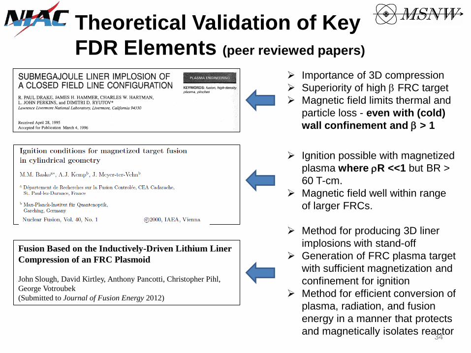
Theoretical Validation of Key FDR Elements (peer reviewed papers)
Importance of 3D compression Superiority of high β FRC target Magnetic field limits thermal and particle loss - even with (cold) wall confinement and β > 1
Ignition possible with magnetized plasma where ρR <<1 but BR > 60 T-cm. Magnetic field well within range of larger FRCs.
Fusion Based on the Inductively-Driven Lithium Liner Compression of an FRC Plasmoid
John Slough, David Kirtley, Anthony Pancotti, Christopher Pihl, George Votroubek (Submitted to Journal of Fusion Energy 2012)
Method for producing 3D liner implosions with stand-off Generation of FRC plasma target with sufficient magnetization and confinement for ignition Method for efficient conversion of plasma, radiation, and fusion energy in a manner that protects and magnetically isolates reactor
34

Initial Mission Studies
Fusion Assumptions: • Ionization cost is 75 MJ/kg
Coupling Efficiency to liner is 50% Thrust conversion ηt ~ 90% Realistic liner mass are 0.28 kg to 0.41 kg
•••
• Corresponds to a Gain of 50 to 500 • Ignition Factor of 5
Safety margin of 2: GF =GF(calc.)/2 •
Mission Assumptions: • Mass of Payload= 61 MT
• Habitat 31 MT Aeroshell 16 MT Descent System 14 MT
••
• Specific Mass of capacitors ~ 1 J/g Specific Mass of Solar Electric Panels 200 W/kg Tankage fraction of 10% (tanks, structure, radiator, etc.) Payload mass fraction =Payload Mass/Initial Mass System Specific Mass = Dry Mass/SEP (kg/kW) Analysis for single transit optimal transit to Mars Full propulsive braking for Mars Capture - no aerobraking
••
•
•••
Trip Time (Days)
Fusi
on G
ain
20 40 60 80 100 12050
100
150
200
250
300
350
Pay
lod
Mas
s Fr
actio
n
0
0.1
0.2
0.3
0.4
0.5
0.6
0.7
0.8
Higher fusion gain and longer trip times
result in higher payload mass fraction
Burn Time (Days)
Tota
l Gai
n
20 40 60 80
50
100
150
200
Pay
lod
Mas
s Fr
actio
n
0
0.1
0.2
0.3
0.4
0.5
0.6
0.7
0.8
Burn time of ~10 days is optimal
Anthony Pancotti, John Slough, David Kirtley, Micheal Pfaff, Christopher Pihl, George Votroubek, “Mission Design Architecture for the Fusion Driven Rocket”, AIAA 48th JPC, July 2012
Pay
load
Mas
s Fr
actio
n P
aylo
ad M
ass
Frac
tion
35

•
•
•
•
Theoretical Validation of Key FDR Elements (peer reviewed papers)
Demonstrated inductively driven liner compression of Bz fields > 1 Mbar
Demonstrated the stable formation, merging and magnetic compression of the FRC FRC lifetime better than previous scaling
Demonstrated successful FRC liner compression with a xenon plasma liner
Hope to publish in the near future! Experimental demonstration of fusion gain with inductively driven metal liners 36
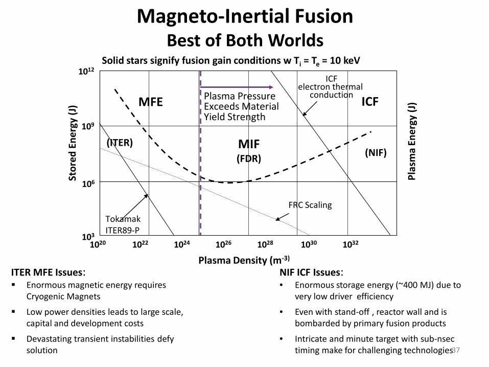
Magneto-Inertial Fusion Best of Both Worlds
ICF electron thermal
conduction ICF
MIF (FDR)
MFE
FRC Scaling Tokamak ITER89-P
Plasma Pressure Exceeds Material Yield Strength
1020 1022 1024 1026 1028 1030 1032
Plasma Density (m-3)
Stor
ed E
nerg
y (J
) 1012
109
106
103
Plas
ma
Ener
gy (J
)
Solid stars signify fusion gain conditions w Ti = Te = 10 keV
(ITER) (NIF)
ITER MFE Issues: Enormous magnetic energy requires
Cryogenic Magnets
Low power densities leads to large scale, capital and development costs
Devastating transient instabilities defy solution
NIF ICF Issues: • Enormous storage energy (~400 MJ) due to
very low driver efficiency
Even with stand-off , reactor wall and is bombarded by primary fusion products
Intricate and minute target with sub-nsec timing make for challenging technologies37
•
•
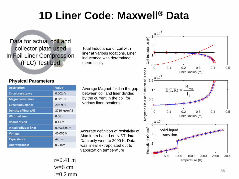
1D Liner Code: Maxwell® Data
Data for actual coil and collector plate used
In Foil Liner Compression (FLC) Test bed
Total Inductance of coil with liner at various locations. Liner inductance was determined theoretically
0 0.1 0.2 0.3 0.4 0.50
1
2
3x 10
-6
Liner Radius (m)
Coi
l Ind
ucta
nce
(H)
Physical Parameters
0 0.1 0.2 0.3 0.4 0.50
0.5
1
1.5x 10
-5
Liner Radius (m)
Mag
netic
Fie
ld a
s fu
ncito
n of
R a
nd I
0 500 1000 1500 2000 2500 30000
2
4
6x 10
-7
Temperature (K)
Res
istiv
ity (O
hms/
m)
c
avg
IB
=R)B(I,
Solid-liquid transition
Description
Circuit resistance
Value
0.002 Ω
Magnet resistance
Circuit inductance
0.001 Ω
20e-9 H
Density of liner (Al)
Width of liner
2710 kg/m^3
0.06 m
Radius of coil 0.41 m
Initial radius of liner 0.403325 m
Voltage
Capacitance
Liner thickness
40,000 V
420 u F
0.2 mm
Average Magnet field in the gap between coil and liner divided by the current in the coil for various liner locations
Accurate definition of resistivity of Aluminum based on NIST data. Data only went to 2000 K. Data was linear extrapolated out to vaporization temperature
r=0.41 m w=6 cm l=0.2 mm
38
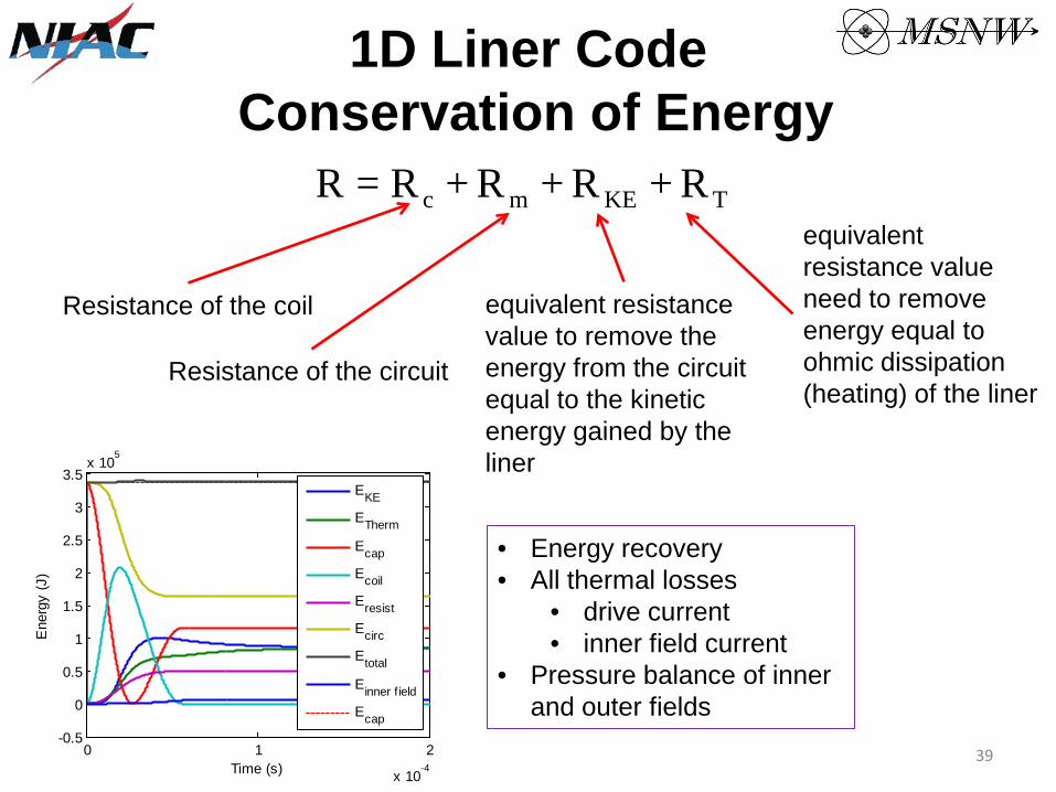
1D Liner Code Conservation of Energy
TKEmc R+R+R+R=R
Resistance of the coil
Resistance of the circuit
equivalent resistance value to remove the energy from the circuit equal to the kinetic energy gained by the liner
equivalent resistance value need to remove energy equal to ohmic dissipation (heating) of the liner
0 1 2
x 10-4
-0.5
0
0.5
1
1.5
2
2.5
3
3.5x 10
5
Time (s)
Ene
rgy
(J)
EKE
ETherm
Ecap
Ecoil
Eresist
Ecirc
Etotal
Einner f ield
Ecap
• Energy recovery All thermal losses •
• drive current inner field current •
• Pressure balance of inner and outer fields
39
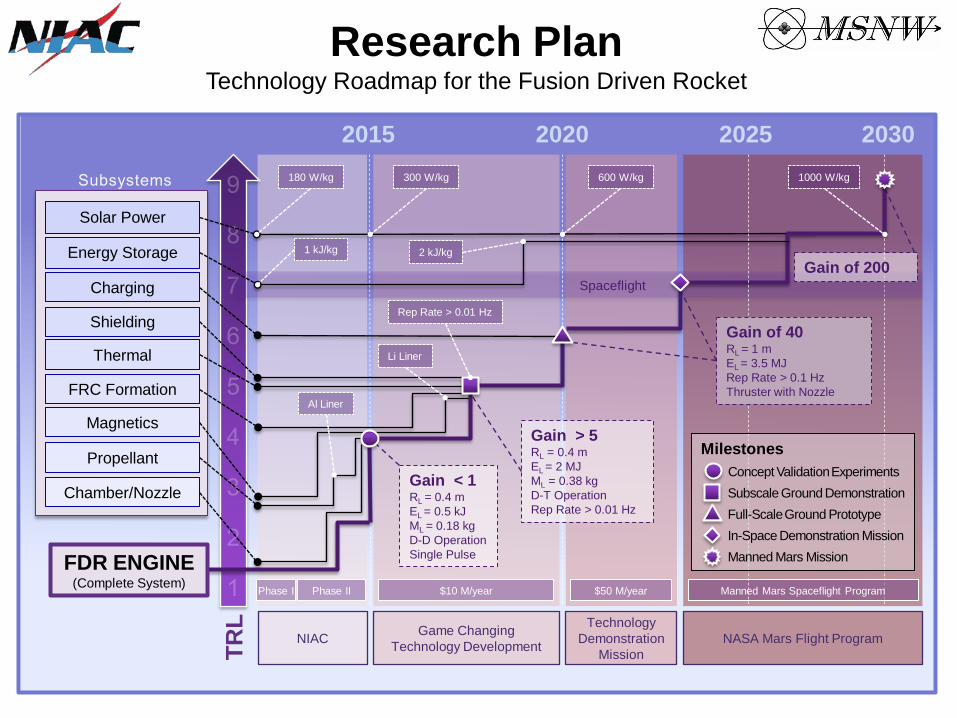
2015 2020 2025 2030
Phase I Phase II $10 M/year $50 M/year
Gain < 1 RL = 0.4 m EL = 0.5 kJ ML = 0.18 kg D-D Operation Single Pulse
600 W/kg 300 W/kg 1000 W/kg 180 W/kg
1 kJ/kg 2 kJ/kg
Spaceflight
NIAC Game Changing Technology Development
Technology Demonstration
Mission NASA Mars Flight Program
Manned Mars Spaceflight Program
TRL
FDR ENGINE (Complete System)
Magnetics
Chamber/Nozzle
FRC Formation
Propellant
Shielding
Thermal
Charging
Energy Storage
Solar Power
Gain > 5 RL = 0.4 m EL = 2 MJ ML = 0.38 kg D-T Operation Rep Rate > 0.01 Hz
Li Liner
Al Liner
Rep Rate > 0.01 Hz
Gain of 40 RL = 1 m EL = 3.5 MJ Rep Rate > 0.1 Hz Thruster with Nozzle
Gain of 200
Milestones Concept Validation Experiments Subscale Ground Demonstration Full-Scale Ground Prototype In-Space Demonstration Mission Manned Mars Mission
Research Plan Technology Roadmap for the Fusion Driven Rocket
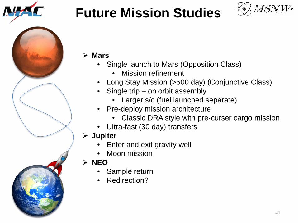
Future Mission Studies
•
•••
••
••
••
••
Mars Single launch to Mars (Opposition Class)
Mission refinement Long Stay Mission (>500 day) (Conjunctive Class) Single trip – on orbit assembly
Larger s/c (fuel launched separate) Pre-deploy mission architecture
Classic DRA style with pre-curser cargo mission Ultra-fast (30 day) transfers
Jupiter Enter and exit gravity well Moon mission
NEO Sample return Redirection?
41
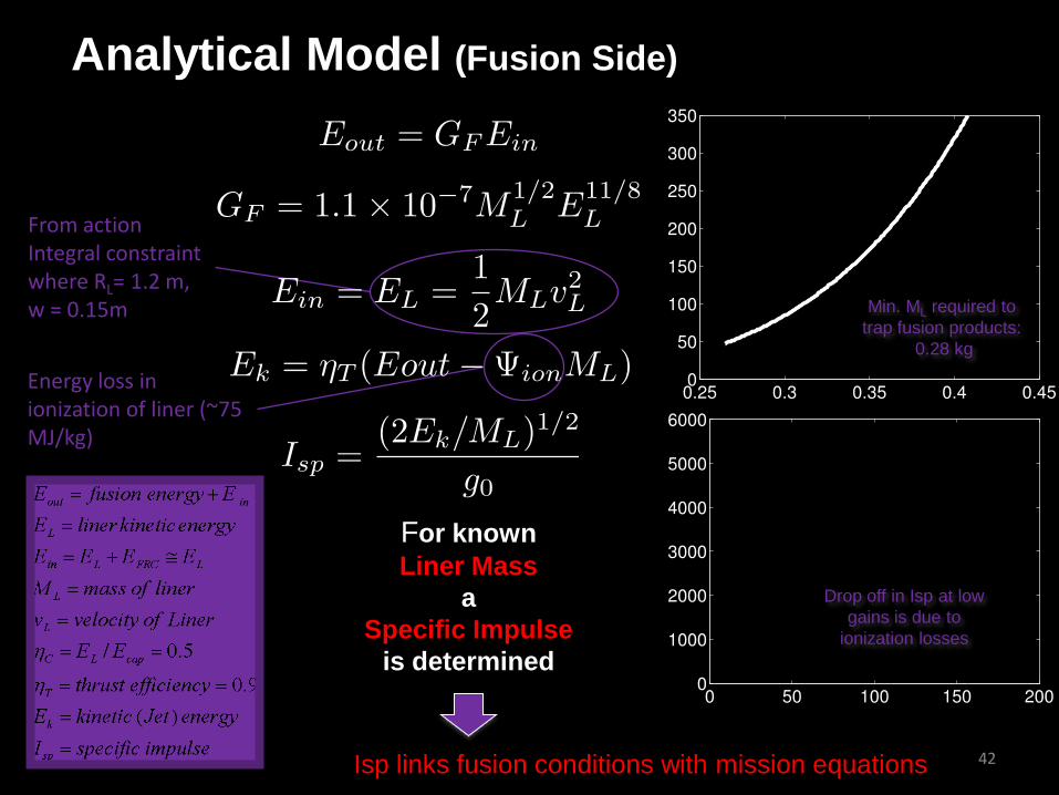
Analytical Model (Fusion Side)
Min. ML required to trap fusion products:
0.28 kg
From action Integral constraint where RL= 1.2 m, w = 0.15m
Energy loss in ionization of liner (~75MJ/kg)
Drop off in Isp at low gains is due to
ionization losses
For known Liner Mass
a Specific Impulse
is determined
Isp links fusion conditions with mission equations 42

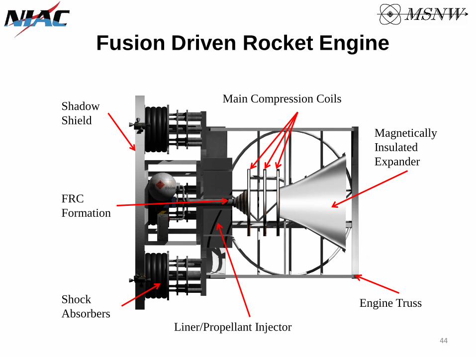
Fusion Driven Rocket Engine
Main Compression Coils
Magnetically Insulated Expander
Engine Truss
Liner/Propellant Injector
Shock Absorbers
FRC Formation
Shadow Shield
43
Fusion Driven Rocket Engine
Main Compression Coils
Magnetically Insulated Expander
Engine Truss
Liner/Propellant Injector
Shock Absorbers
FRC Formation
Shadow Shield
44
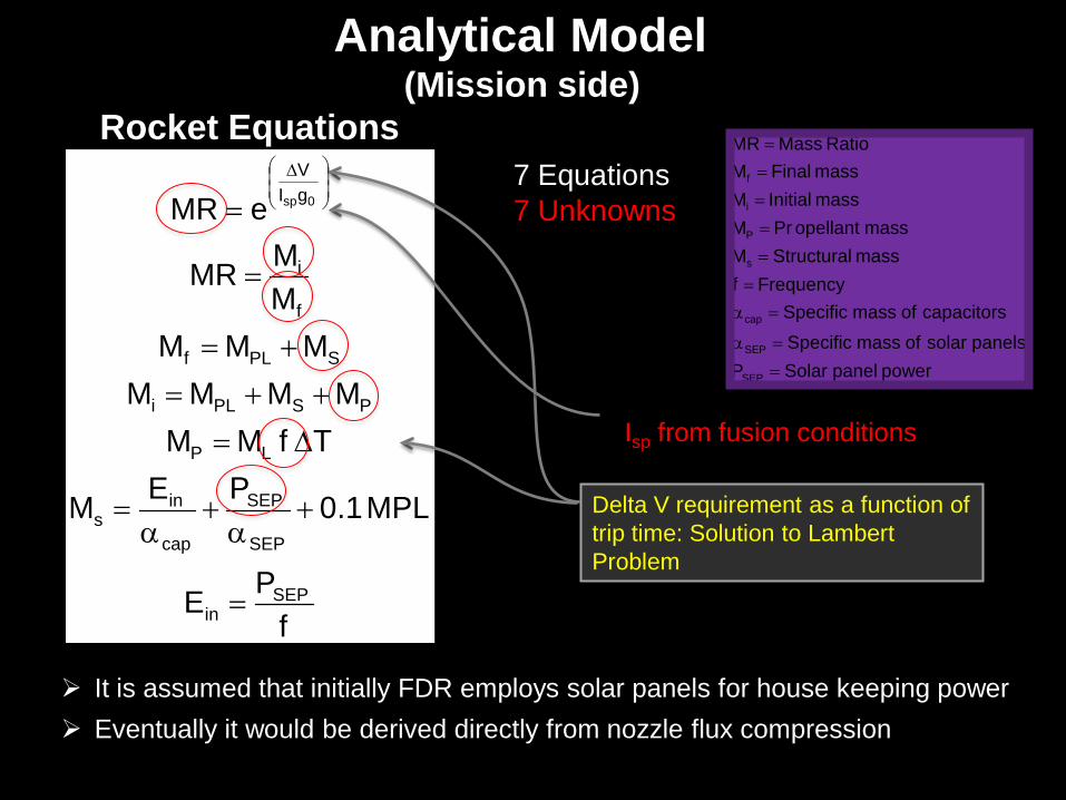
Analytical Model (Mission side)
Rocket Equations
PE
MPL1.0PEM
TfMMMMMM
MMMMMMR
eMR
SEPin
SEP
SEP
cap
ins
LP
PSPLi
SPLf
f
i
gIV
0sp
=
+α
+α
=
∆=
++=
+=
=
=
∆
f
7 Equations 7 Unknowns
MR = Mass RatioMf = Final massMi = Initial massMP = Pr opellant massMs = Structural massf = Frequencyαcap = Specific mass of capacitorsαSEP = Specific mass of solar panelsPSEP = Solar panel power
Isp from fusion conditions
Delta V requirement as a function of trip time: Solution to Lambert Problem
It is assumed that initially FDR employs solar panels for house keeping power Eventually it would be derived directly from nozzle flux compression