Electromagnetic compatibility of integrated circuit clock ...

Electromagnetic Energy Harvesting Circuit with Feedforward and Feedback
DC-DC PWM Boost Converter for Vibration Power Generator System
Xinping Cao1, Wen-Ren Chiang2, Ya-Chin King2 and Yi-Kuen Lee1
1Department of Mechanical Engineering, Hong Kong University of Science and Technology
Clear Water Bay, Kowloon, Hong Kong
2Department of Electrical Engineering, National Tsing Hua University Taiwan, ROC
Abstract—This paper presents an integrated vibration power generator system. The system consists of a
mini electromagnetic vibration power generator and a highly efficient energy harvesting circuit
implemented on a minute PCB and a 0.35 μm CMOS integrated chip. By introducing a feedback control
into the DC-DC PWM Boost Converter with feedforward control, the energy harvesting circuit can adjust
the duty ratio of the converter following the variation of the input voltage and the voltage of energy storage
element to get high energy conversion efficiency. The energy harvesting circuit rectifies the input AC
voltage, step up the DC output of the rectifier by the DC-DC PWM Boost Converter with feedforward and
feedback control and store the electric energy into a super capacitor, which can be used as a small electrical
power supply for an intelligent micro sensor network.
Index Terms— DC-DC PWM boost converter, energy harvesting, integrated power generator, micro
sensor network, vibration.
X. Cao, et al., “Electromagnetic Energy Harvesting Circuit With Feedforward and Feedback DC-DC PWM Boost Converter for Vibration Power Generator System,” IEEE Transactions on Power Electronics, Vol. 22, No. 2, pp. 679-685, 2007. http://dx.doi.org/10.1109/TPEL.2006.890009

1
I. INTRODUCTION
Vibration powered electronic devices have been applied in several commercial products, such as Seiko Kinetic wristwatch [1],
smart tennis racquet [2] and smart sports shoes [3]. In recent years, the rapid development of micro sensors for various
applications [4], including remote environmental monitoring, homeland security, automotive sensors and biomedical sensors,
require a miniaturized integrated distributed power supply to reduce potential problems, such as complicated interconnection,
electronic noise and power control system complexity. In many of these micro sensors, power supplies from chemical energy
sources are undesirable due to limited shelf life and replacement accessibility [5]-[7]. To solve this power supply problem, the
conversion of electrical energy from a vibrating source to a renewable storage device [8, 9], such as rechargeable batteries or
super capacitors [10], has been shown to be a potential and promising alternative solution [11,12]. The electrical energy stored in
the storage device can be readily used for low-power ICs or integrated distributed micro sensors [13].
Since it is quite easy to keep a strong magnetic field with a permanent magnet, electromagnetic vibration-power generators are
preferred in many applications. Some pioneering studies on mini electromagnetic vibration-power generators were performed by
researchers at the University of Sheffield [5] and MIT [13]. Their work indicated that a simple spring mass system can generate
power at the level of 1 μW. Researchers at Southampton University fabricated a vibration-based electromechanical power
generator with a power generation of more than 1 mW [6]. Another generator designed and fabricated by the same research
group has been shown to produce a peak power of 157 μW when the power generator was tested on an engine block [14]. Ching
et al. [15] reported a millimeter-sized multi-modal vibration power generator using laser micromachining which can generated a
maximum power of 830 μW. Boland et al. [16] presented a micromachined rotational electret power generator with a output
power greater than 25 μW at the rotation speed of 4170 rpm. Goto et al. [17] reported an automatic power-generating system
(AGS), modified from a Seiko Kinetic quartz watch, for implantable cardiac pacemakers. This AGS system which can generate
13 μJ per heart beat, after fully charged, can be used to pace a mongrel dog's heart at 140 beats min-1 for 60 minutes. Poulin et al.
[18] presented the design and numerical analysis of an electromagnetic and a piezoelectric energy-harvesting system, for
portable electronic devices, which can generate electric powers of 0.21 mW and 5.6×10⁻³ mW, respectively. Jeon et al. [19]
developed a MEMS power generator, which consists of a 170 μm × 260 μm lead zirconate titanate (PZT) beam, with the output
power of 1 μW. Comparison of these vibration power generators is summarized in Table 1.
This paper reports design, fabrication and characterization of a new mini integrated power generator system, with the
maximum output power level of 35 mW, which consists of a mini electromagnetic power generator, an interface electronic
circuit and an energy storage device. The interface circuit introduces a feedback control into a feedforward DC-DC PWM Boost

2
Converter as an energy harvesting circuit and shows high energy conversion efficiency. This circuit was first implemented on a
mini Printed Circuit Board (PCB) and then on a 0.35 μm CMOS IC chip (TSMC 2P4M CMOS technology) and can be used for
the intelligent sensor networks [20].
II. THE MINI ELECTROMAGNETIC POWER GENERATOR
A mini electromagnetic power generator consists of a copper coil, a permanent magnet (also acting as a mass) and a spring.
The permanent magnet is attached to the coil through the spring. The system works in such a manner that when there is a
vibration input, the coil cuts through the magnetic flux formed by the permanent magnet due to the relative displacement
between the permanent magnet and the coil. A sinusoidal electromotive force in the coil can be generated and thus transfers
mechanical energy into electrical energy. Since the output power of the power generator is quite small, an energy harvesting
interface circuit with high power transfer efficiency needs to be developed to recharge and store the electrical power into the
energy storage elements. Furthermore, since the voltage of the renewable power supply must be high enough, the voltage should
be increased to an acceptable level.
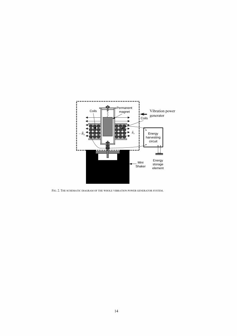
A mini electromagnetic power generator was fabricated at the Hong Kong University of Science and Technology as shown in
Fig. 1, which is designed to generate power from the vibration of an automobile and other vehicles. There is a screw at the
bottom of the power generator and a screw nut at the top of the mini-shaker. Therefore, the power generator firmly fixed on the
shaker can have controlled vertical vibration as shown in Fig. 2. The maximum power that this device can generate is given by
[5]:
2max
3max ZmP ntωζ= (1)
n
t mcω
ζ2
= (2)
where m is the mass of the permanent magnet, ζt is the damping ratio; c is the damping coefficient; ωn is the resonant frequency
of the vibration power generator. Zmax is the maximum relative displacement between the coil and the permanent magnet. Here
the resonant frequency of the designed power generator is 40 Hz. The amplitude of the oscillation produced by the mini-shaker
is 3 mm.
III. DESIGN OF ENERGY HARVESTING CIRCUIT
Since an electromagnetic power device generates an AC voltage while a power storage element usually requires a DC voltage
input, an energy harvesting circuit needs an AC-DC rectifier connected to the two ends of the coil of the power generator in the

3
first stage. If the output voltage of the rectifier is greater than that of the energy storage element, the electrical power can be
directly harvested.
A. Boost converter
In many cases, the output voltage of the rectifier is smaller than that of the storage element. Therefore, it must be stepped up to
be harvested into the energy storage element. In this case, a switching-mode boost DC-DC converter, as shown in Fig. 3, is used
to step up the output voltage of the rectifier. In general, the ideal switch, diode and inductor should be replaced with components
in series with corresponding parasitic resistors.
For a typical boost converter [21, 22], the voltage gain M between the input and output voltage can be expressed by the
following equation if the parasitic Rc of the capacitor is negligible:
o
RD
o
RL
o
Rsg
o
VV
VV
DVV
DDVV
M+′++′
==1 (3)
DD −=′ 1
where the duty ratio D is defined as the ratio of the ‘on’ cycle time ton to the whole period T, TtD on /= . By invoking the
volt-second balance principle, the conversion efficiency can be written as
RDRDR
RDR LsD
21
1
′+
+′
+=η (4)
where DD −=′ 1 and R, RD, RL, Rs are the parasitic series resistors shown in Fig. 3.
Therefore, the efficiency is obtained and shown as a function of duty ratio for different load resistances in Fig. 4.
B. Feedforward control of DC-DC PWM Boost Converter
For a certain power output level of the power generator, energy harvesting circuit should converter the electrical energy and
recharge it into energy storage element effectively. Using a constant-duty ratio, the output voltage of the DC-DC boost converter
is directly proportional to the DC input voltages. Since typical vibration input during normal operation is random, the rectifier
has a wide range of output voltage. Based on Equation 4, it should be possible to achieve higher energy conversion efficiency
than the DC-DC converter with a constant-duty ratio in such case. The feedforward control of DC-DC PWM Boost Converter
(Fig. 5) is simple and can significantly improve the performance of this DC-DC power conversion [11]. The principle of
operation can be explained by the waveforms of vt, VREF and vGS shown in Fig. 6. When the reference voltage VREF at the
noninverting input is higher than the sawtooth voltage, the gate to source voltage vGS goes low, otherwise, the voltage vGS goes
high. Therefore, the complement of the on-duty cycle is proportional to the DC converter input voltage.

4
For the feedforward control of DC-DC PWM Boost Converter, the relationship between the rated output voltage, Vo, and the
sawtooth voltage is
( ) 021 1 sO VRRV += (5)
where Vs0 is the peak value of the sawtooth voltage.
C. Feedfoward and feedback control of DC-DC PWM Boost Converter
Since the voltage of the energy storage element can often vary, the output voltage of the ideal DC-DC converter should be
adjusted accordingly. Therefore, a feedback control circuit is introduced into the feedforward control of DC-DC PWM Boost
Converter circuit as illustrated in Fig. 7. In this new circuit, the sawtooth voltage Vs is
( ) ( )( )tCRRRRRess e
RRRVtV
11
14343 )/(
43
4 1−−++−−
+= (6)
where Ves is the voltage of the energy storage element.
For the case of 43 , RRRR >>>> , the sawtooth voltage can be written as follows:
( ) ( )1143
4 RCtess e
RRRVtV −−+
≈ (7)
Considering the switching period RCt << , the sawtooth voltage can be approximated by a simple expression:
( ) ⎟⎟⎠
⎞⎜⎜⎝
⎛+
≈143
4
RCt
RRR
VtV ess (8)
When the switch M1 is on, the sawtooth voltage reaches its peak value and t can be expressed as follows:
TDt psw )1( −= (9)
where Dp is the on-duty cycle of M and T is the period of the duty cycle of PWM boost converter.
The sawtooth peak value is directly proportional to the voltage of the energy storage element.
CRTD
RRR
VV pess
143
40
)1( −
+≈ (10)
In Fig. 7, M turns on when REFs VV ≥ , thus the time toff can be determine as
TD
CRR
RRV
Vtpes
REFoff )1(
)( 1
4
43
−+
= (11)
here, toff is the time when the switch M is off.
( )TDtoff −= 1 (12)

5
TD
CRR
RRRR
RVVTD
pes )1()(
)()1( 1
4
43
21
21
−+
+=− (13)
The principle of operation of the feedforward and feedback control of DC-DC PWWM boost converter can be explained by the
waveforms of vt, VREF and vGS shown in Fig. 8. Compared with the Feedforward control of a DC-DC PWM boost converter, the
peak value of the sawtooth voltage, Vs0, of the circuit with feedback control increases in direct ratio with the voltage of the
energy storage element. The DC-DC PWM Boost Converter with feedforward and feedback control was first implemented using
discrete components on a mini PCB board and tested to verify the proof of our design concept. The results are measured and
show that duty ratio increase with the voltage of the energy storage element (Fig. 9). From Eqn. (3), the smaller the duty ratio Dp,
the higher the conversion efficiency. That means the circuit can adjust the energy conversion efficiency with the variation of the
voltage of the energy storage element. This adjustability is better for comparatively large input voltage since the duty ratio shows
a stronger dependence on the voltage of the energy storage element for a large input voltage. Based on the Equation (13), the
behaviors of the function represented on Fig. 9 can find its theoretical explanation.
D. Energy harvesting circuit with Feedfoward and feedback control of DC-DC PWM Boost Converter
Fig. 10 shows the energy harvesting circuits with the feedforward and feedback control of DC-DC PWWM boost converter.
In this design, when the DC output voltage of the rectifier is greater than that of the energy storage element, the diode D6 will be
conducted and the electric energy can be recharged into the energy storage element (super capacitor) directly. In other cases, the
output voltage of the rectifier will be increased by the DC-DC PWM boost converter with the feedforward and feedback control
and get the energy storage element recharged.
Using Eq. (13), it comes
( )( )
( ) 21
4
43
21
21
1)1(
TDCR
RRR
RRR
VV
DDpes −
++
=′=− (14)
So, the duty is,
( )( )
( ) 21
4
43
21
21
11
TDCR
RRR
RRR
VV
Dpes −
++
−= (15)
For the case tht the power loss of the rectifier is negligible, the maximum power harvested by the system can be derived from Eqs.
(1) and (4) as follows:
RDRDR
RDR
Zm
ZmP
LsD
nt
nttatal
2
2max
3
2max
3
1′
++
′+
=
=
ωζ
ωηζ
(16)

6
The measured AC output voltage of the power generator as a function of the driving frequency of the mini shaker is shown in
Fig 11. After verifying the proof of our design concept using discrete components as shown in Fig 12, an integrated energy
harvesting with the same schematic structures as on the PCB board circuit was designed and fabricated using TSMC 0.35μm
2P4M CMOS technology via the CIC foundry service (National Chip Implementation Center, Hsinchu, Taiwan).
The integrated circuit designed has 752 MOS transistors totally. The layout of the core circuits is shown in Fig. 13, it consists
of an AC-DC rectifier, a 555-timer circuit as a duty cycle generator, a step-up DC-DC converter and feedforward and feedback
control circuit. The 555-timer circuit is designed to produce desired duty cycle. Modified by the feedforward and feedback
control circuit, the duty cycle is used to turn on/off the switches of the step-up DC-DC converter. The converter steps up the
output DC voltage of the rectifier. The final output energy is stored into an energy storage element off-chip.
IV. CHARACTERIZATION OF THE MINI VIBRATION POWER GENERATOR SYSTEM
The open-circuit coil voltage (Vcoil) of the fabricated power generator as a function of vibration frequency was measured using
a Dynamic Signal Analyzer (#35665A, Hewlett Packard Co., USA) and a mini electromagnetic shaker (#1640268, Brüel &
Kjær, Nærum, Denmark). Fig. 14 shows the sawtooth-wave voltage and duty-cycle voltage measured by an oscilloscope. The
energy harvesting circuit has been shown to convert the vibration energy from the shaker to electrical energy and then to supply
enough power for a micro sensor network consisting of 4 commercial micro accelerometers (ADXL322, Analog Devices Inc,
Norwood, MA, USA).
The required power for one ADXL chip ranges from 1.2 mW (at 2.4 V supply voltage) to 3 mW (at 6 V) according to the
specification of the device datasheet. When the shaker was vibrating at the resonant frequency of the power generator, the
maximum output power level of 35 mW and the power density of 0.41 mW/cm3 was achieved. The volumes of the two energy
harvesting devices and the specific power (output power/volume) of the energy harvesting devices, (IC chip based = 0.13
mW/cm3 & PCB based systems = 0.41 mW/cm3) which is harvested into a super capacitor, are calculated. Furthermore, the
volumes of the devices are found, which are made by other researchers mentioned in Introduction section and the specific power
are also calculated (Table 1).
Finally, an integrated energy harvesting circuit was designed with the EDA software package of Cadence® (Cadence Design
Systems Inc., San Jose, CA, USA) and fabricated using the TSMC® 0.35μm 2P4M CMOS foundry service. Figs. 15(a) and 15(b)
show the photographs of one die without and with electronic packaging, respectively. Testing results show that the chip can
boost the input voltage and store electrical energy into a big capacitor effectively. Table 2 summarizes the performance
comparison of the fabricated CIC chip and the corresponding discrete circuit on a PCB board.

7
V. CONCLUSIONS
An electromagnetic power generator with a high-performance the feedforward and feedback DC-DC PWM Boost Converter
energy harvesting circuit, which was implemented on a PCB board first and then on a 0.35 μm CMOS IC chip, has been
designed and fabricated. By introducing a feedback control into a feedforward DC-DC PWM Boost Converter, the energy
harvesting circuit shows high energy conversion efficiency. The measured dependence of the duty ratio of the feedforward and
feedback DC-DC PWM boost converter on the voltage of the energy storage element confirms the high energy conversion
efficiency of the circuit. Using a mini shaker as a vibration source, the maximum output power of 35 mW has been successfully
harvested and applied to drive four commercial micro accelerometers.
ACKNOWLEDGMENT
This work is supported by the Institute of Integrated Microsystems, HKUST (contract # I2MS01/02.EG08). The authors
would like to acknowledge the TSMC CMOS foundry service from the National Chip Implementation Center, Taiwan, ROC
(http://www.cic.org.tw). In addition, the authors would like to thank Michael Cheng in Analog Devices (HK) Inc. to provide free
ADXL 322 micro accelerometers and Pak Kin Leung at HKUST to take the micrographs of the microchip.

8
REFERENCES
[1] N. Hayakawa, “A study of the new energy system for quartzwatches (II)-The effective circuit for the system,” Proc. Congrès Europé́en de Chronomé́trie,
1988, pp. 81-85.
[2] J. Yoshida, “Piezoelectric rackets add professional oomph,” Electronic Engineering Times (EE Times, CMP Publications, Manhasset, NY, USA), June 10,
2002. Available:http://www.eetimes.com
[3] W. Knight, “Smart sports shoe adapts for optimal cushioning,” New Scientist, May 6, 2004. Available:
http://www.newscientist.com/news/news.jsp?id=ns99994969
[4] C.-Y. Chong and S. P. Kumar, “Sensor networks: evolution, opportunities, and challenges,” Proceedings of the IEEE, 91, 2003, pp. 1247-1256.
[5] C. B. Williams and R. B. Yates, “Analysis of a micro-electric generator for microsystems,” Sensors and Actuators A 52 1996, pp. 8-11.
[6] M. El-hami, P. Glynne-Jones, N. M. White, M. Hill, S. Beeby, E. James, A. D. Brown and J. N. Ross, “Design and fabrication of a new vibration-based
electromechanical power generator”, Sensors and Actuators A 92 2001, pp. 335-342.
[7] T. Starner, “Human-powered wearable computing,” IBM Systems Journal, vol 35, 1996 pp. 618-629.
[8] Geffrey K. Ottman, Heath F. Heath F. Hofmann, Archin C. Bhatt and George A. Lesieutre, “Adaptive piezoelectric energy harvesting circuit for wireless
remote power supply”, IEEE Trans. Power Electron., vol. 17, pp. 669-676, September 2002.
[9] Geffrey K. Ottman, Heath F. Hofmann and George A. Lesieutre, “Optimized piezoelectric energy harvesting circuit using step-down converter in
discontinuous conduction mode”, IEEE Trans. Power Electron., vol. 18, pp. 696-703, March 2003
[10] M. K. Kazimierczuk and R. C. Cravens, “Application of super capacitors for voltage regulation in distributed power systems,” in: IEEE Power Electronics
Specialists Conference, Baveno, Italy, June 23-27,1996, pp. 835-841.
[11] S. Meninger, J. O. Mur-Miranda, R. Amirtharajah, A. P. Chandrakasan and J. H. Lang, “Vibration-to-electric energy conversion,” IEEE Transactions on
VLSI, vol . 9, 2001, pp. 64-76.
[12] P. B. Koeneman, I. J. Busch-Vishniac and K. L. Wood, Feasibility of Micro Power.
[13] R. Amirtharajah and A. P. Chandrakasan, “Self-powered signal processing using vibration-based power generation,” IEEE J. Solid-State Circuits, vol. 33
1998, pp. 687-695.
[14] P. Glynne-Jones, M. J. Tudor, S. P. Beeby and N. M. White, “An electromagnetic, vibration-powered generator for intelligent sensor systems,” Sensors
and Actuators A 110, 2004, pp. 344-349.
[15] N. N. H. Ching, H. Y. Wong, W. J. Li, P. H. W. Leong and Z. Wen, “A laser-micromachined multi-modal resonating power transducer for wireless sensing
systems,” Sensors and Actuators A 97, 2002, pp. 685-690.
[16] J. Boland, Y. H. Chao, Y. Suzuki and Y.C. Tai, “Micro electret power generator,” in: Proceedings of The Sixteenth IEEE International Conference on
Micro Electro Mechanical Systems (MEMS '03), Kyoto, Japan, Jan. 19-23, 2003, pp. 538-541.
[17] H. Goto, T. Sugiura, Y. Harada and T. Kazui, “Feasibility of using the automatic generating system for quartz watches as a leadless pacemaker power
source,” Medical and Biological Engineering and Computing vol. 37 1999, pp. 377-380.
[18] G. Poulin, E. Sarraute, F. Costa, “Generation of electrical energy for portable devices Comparative study of an electromagnetic and a piezoelectric
system,” Sensors and Actuators A 116 2005, pp. 461-471.
[19] Y. B. Joen, R. Sood, J.-H. Jeong, S.-G. Kim, “MEMS power generator with transverse mode thin film PZT,” Sensors and Actuators A 122, 2005, pp. 16-22.
[20] M. K. Kazimierczuk and A. Massarini, “Feedforward control of DC-DC PWM boost converter,” IEEE Trans on Circuits and Systems, vol. 44 1997, pp.
143-148.

9
[21] M. H. Rashid, Power Electronics, Circuits, Devices and Applications, 2nd , Prentice Hall, Englewood Cliff, NJ, USA, Chapter 9, 1998.
[22] N. Mohan, T. M. Undeland, W. P. Robbins, Power Electronics : Converters, Applications, and Design, John Wiley & Sons, Hoboken, NJ, USA, Chapter
7, 2003.

10
Xinping Cao obtained a PhD degree in Microelectronics from Peking University, Beijing, China, in 2002, he obtained his MSc in microelectronics from The
Changchun Institute of Optics and Fine Mechanics, Changchun, China in 1999, and the BSc degree in Physics from Xinjiang University , Xinjiang, China in
1996.
He was a Research Associate at the Hong Kong University of Science and Technology, Hong Kong in 2003. His major research interests focus on MEMS
technologies and Analog Integrated Circuits. Currently, he is working for the School of Electrical and Electronic Engineering, Nanyang Technological
University, Singapore.
Wen-Ren Chiang obtained his B.S. degree in Engineering and System Science from the National Tsing Hua University, Hsinchu, Taiwan, ROC in 2002.
Currently, He is a PhD student at the Institute of Electronics Engineering, National Tsing Hua University. His major research interests are the circuit design
of CMOS image sensors.
Ya-Chin King received the BSc degree in electrical engineering from National Taiwan University in 1992, and the MSc degree in electrical engineering from
the University of California, Berkeley, in 1994. She received her PhD degree in May of 1999, at University of California, Berkeley, on thin oxide technology
and novel quasi-nonvolatile memory.
She joined the faculty of National Tsing-Hua University at Hsinchu, Taiwan in August 1999. She is currently an Associate Professor of the Electrical
Engineering Department at NTHU. Her research topics include: advance gate dielectric, CMOS image sensors and non-volatile memory design.
Yi-Kuen Lee has been an assistant professor in the Department of Mechanical Engineering, Hong Kong University of Science and Technology since 2001. He
received his BSc and MSc degrees at the National Taiwan University, Taipei, Taiwan, ROC in 1992 and 1995, respectively. He obtained his PhD in Mechanical
Engineering with MEMS as the major subject in Prof Chih-Ming Ho’s laboratory, University of California, Los Angles in 2001.
He is an Assistant Professor in the Hong Kong University of Science and Technology. His research interests at HKUST include micro sensors and actuators,
micro/nanofluidics, and bio-MEMS.

11
TABLE I
SUMMERY OF THE SPECIFIC POWER AND THE VOLUME OF VARIOUS VIBRATION POWER GENERATORS REPORTED IN THE LITERATURE
Researchers Specific power mW/cm3
Frequency (Hz)
Amplitude (mm)
Ref 6 4.2 320 0.94 Ref 14 0.05 322 0.36 Ref 15 0.8 60~110 0.2 Ref 18 0.071 2 5 Ref 19 0.74 13.9 0.0045
Our work 0.41 & 0.13 42 3

12
TABLE 2
PERFORMANCE COMPARISON BETWEEN THE SYSTEMS WITH A DISCRETE INTERFACE CIRCUIT AND THE INTEGRATED INTERFACE CIRCUIT
ITEMS CMOS IC chip PCB based circuit
Operating voltage (V) 3.3 3.3
The frequency of duty cycle generator (kHz) 63–100 10–1000
Die/PCB Area (cm2) 0.03 49
The highest Output Voltage (V) 3.7 4.5
Max Output power (mW) 4.0 35
Volume of the systems (cm3) 31.5 86 The specific power (mW/cm3) 0.13 0.41

13
Fig. 1. Photograph of the mini vibrational power generator.
1cm
Spring
Coil Mini- shaker
Magnet (mass)
Frame screw
14
hBr
hBr
− Energyharvesting
circuit
Energystorageelement
CoilsPermanent
magnet
MiniShaker
Coils
FIG. 2. THE SCHEMATIC DIAGRAM OF THE WHOLE VIBRATION POWER GENERATOR SYSTEM.
Vibration power generator

15
Rs
RLL
Vg
D RD
Rc
C
RVo
Fig. 3. Typical boost converter
Switch

16
Fig. 4. Power conversion efficiency as a function of duty ratio for different load resistances for a practical boost
converter. The unit for the resistance R is Ohm (RL=6.0Ω, Rs=1Ω and RD=9Ω).

17
+
-
ComparatorR1
R2
V1+
-M
L1 D1
V2
V+V-
C RL
Fig. 5. Feedforward control of a DC-DC PWM boost converter.
Sawtooth wave
VREF
VGS
+
-

18
( )tV s
R E FV
G SVo nS
o f fS
T 2 T 3 T
G SVo nS
o f fS
( )tV s
R E FV
T 2 T 3 T
( 1 - D ) t D t
( 1 - D ) t D t
t
t
V s 0
V s 0
Fig. 6. Waveforms in the feedforward control circuit of Fig. 5

19
L1 D5
+
-
ComparatorR1
R2
M
V+V-
Co
C1
R3
R4
R
M1
V1+
-
Fig. 7. Feedforward and feedback control of DC-DC PWWM boost converter.
Sawtooth Vs
Ves
Boost converter
VREF
-
VGS
+
-
Feedback control
Fixed duty cycle voltage
Feedfoward control

20
R E FV
G SVo nS
o ffS
G SVo nS
o ffS
( )tV s
( )tV s
R E FV
T 2 T 3 T
T 2 T 3 T
(1 -D ) t D t
(1 -D ) t D t
t
t
V s 0
V s 0
Fig. 8. Waveforms in the feedforward and feedback control circuit of Fig. 5

21
3 4 50.70
0.75
0.80
0.85
0.90
0.95
Duty
Rat
io
Vo (V)
Vi=0.4 Vi=0.6 Vi=0.8 Vi=1.0 Vi=1.2 Vi=1.4
Fig. 9. Duty ratio as a function of the output voltage for different input voltages
of a DC-DC PWM boost converter with feedforward and feedback control.

22
+
-
ComparatorR1
R2
M
L1 D5
V+V-
Co
C1
R3
R4
R
M1
D2
D1
D3
D4Vcoil
D6
Fig. 10. Energy harvesting circuit with feedforward and feedback control of DC-DC PWWM boost converter. Sawtooth Vs
Boost converter
VREF
VGS +-
Feedback control
Fixed duty cycle voltage
Feedfoward control
Rectifie
Super capacitor

23
0
4
8
12
16
20 40 60
Frequency (Hz)
Vco
il (V
)
Fig. 11. Measured output voltage of the mini vibration power generator as a function of the driving frequency of the mini shaker. The
amplitude of the driving motion is 3 mm, the magnetic field strength is 1.1 T and the effective coil length is 1.2 km.

24
Fig. 12. Discrete circuit implementation of the energy harvesting circuit on a printed circuit board.
1cm

25
Duty cycle Generand feedforward feedback control cir
50μm
Switch
Rectifier
Fig. 13. Layout for the 0.35μm CMOS integrated energy harvesting circuit.

26
(a) (b)
Fig. 14. Snapshots of the voltages in the energy harvesting circuit on an oscilloscope, (a) the sawtooth-wave voltage Vs, (b) the voltage
of the feedback-control duty cycle.

27
100um 1mm
(a) (b) Fig. 15. Photographs of the energy-harvesting CMOS IC chip: (a) a fabricated die, (b) a DIP packaged chip.


![Electromagnetic Energy Harvesting Circuit with Feedforward ... · smart tennis racquet [2] and smart sports shoes [3]. In recent years, the rapid development of micro sensors for](https://static.fdocuments.net/doc/165x107/6017abf0bb502a633d02dcfc/electromagnetic-energy-harvesting-circuit-with-feedforward-smart-tennis-racquet.jpg)