Electrohydraulic Oil Supply Unit EHC-U
6
E 2.164.0/10.13 Electrohydraulic Oil Supply Unit EHC-U
Transcript of Electrohydraulic Oil Supply Unit EHC-U
E 2
.164
.0/1
0.13
Electrohydraulic Oil Supply Unit EHC-U

2
E 2
.164
.0/1
0.13
Highly Available Oil Supply by Modularized Redundancy
Electrohydraulic Oil Supply Unit EHC-U
M
pI
pI
LI
TI
T
7
T
p
IL
I
M
M
M
Option RF
Option MP
Option RP
Option RS
Option CW
Option CA
Option RS
Option OP
Option HOption VOption V
4
1
23
5
6
899
7 76
10 10
11 11
12 12
13
13 13
13
14
15
16
16 18
17 17
19
20
21
22
25
26
2828
2828
29 29
27
23
24
30
Circuit Diagram of the Oil Supply Unit EHC-U
For the operation of the electrohydraulic actuators of the EHC family oil supply units with reservoir are needed that provide the operating medium with sufficient flow and pressure.
The provision of the oil is done by an electric motor-driven pump with a pressure relief valve.
Deviations between the oil consumption and the flow rate can be compensated by hydraulic accumulators with safety valve.
The necessary cleanliness of the oil is provided by a pressure filter with differential pressure monitor. Level, temperature and pressure of the oil and the contamination of the filter are monitored by sensors and switches.
On the one hand, the modular design allows for critical components to be integrated into a redundant setup. In particular, the option to double the motor-pump group provides an increase in the availability of the unit. A redundant layout of sensors and switches can also be selected.
On the other hand, depending on the application requirements, the oil supply unit can optionally be equipped with additional components, for example heating and cooling for an adapted temperature of the oil.
With the optional manual pump the operation of the powered actuators is possible in case of maintenance. If necessary, an oil drip pan with sufficient size to accomodate the entire volume of the reservoir can be added.
The oil supply unit can be equipped with either constant displacement pumps or pressure-compensated variable displacement pumps. The components with electrical connection are wired to a terminal box.
The availability of hydraulic systems depends on the condition of the operating oil.EHC-U units can be optionally equipped with Condition Monitoring Systems for this purpose.
3
E 2
.164
.0/1
0.13
M
pI
pI
LI
TI
T
7
T
p
IL
I
M
M
M
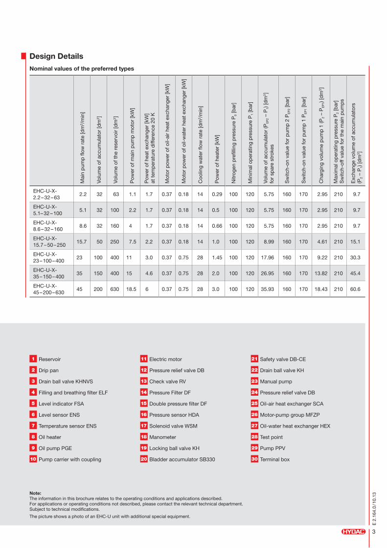
1 Reservoir
2 Drip pan
3 Drain ball valve KHNVS
4 Filling and breathing filter ELF
5 Level indicator FSA
6 Level sensor ENS
7 Temperature sensor ENS
8 Oil heater
9 Oil pump PGE
10 Pump carrier with coupling
11 Electric motor
12 Pressure relief valve DB
13 Check valve RV
14 Pressure Filter DF
15 Double pressure filter DF
16 Pressure sensor HDA
17 Solenoid valve WSM
18 Manometer
19 Locking ball valve KH
20 Bladder accumulator SB330
21 Safety valve DB-CE
22 Drain ball valve KH
23 Manual pump
24 Pressure relief valve DB
25 Oil-air heat exchanger SCA
26 Motor-pump group MFZP
27 Oil-water heat exchanger HEX
28 Test point
29 Pump PPV
30 Terminal box
Design Details
Nominal values of the preferred types
Mai
n p
ump
flow
rat
e [d
m3 /
min
]
Volu
me
of a
ccum
ulat
or [d
m3 ]
Volu
me
of t
he r
eser
voir
[dm
3 ]
Pow
er o
f mai
n p
ump
mot
or [k
W]
Pow
er o
f hea
t ex
chan
ger
[kW
] at
tem
per
atur
e d
iffer
ence
20
K
Mot
or p
ower
of o
il-ai
r he
at e
xcha
nger
[kW
]
Mot
or p
ower
of o
il-w
ater
hea
t exc
hang
er [k
W]
Coo
ling
wat
er fl
ow r
ate
[dm
3 /m
in]
Pow
er o
f hea
ter
[kW
]
Nitr
ogen
pre
fillin
g p
ress
ure
P0
[bar
]
Min
imal
op
erat
ing
pre
ssur
e P
1 [b
ar]
Volu
me
of a
ccum
ulat
or (P
EP
2 –
P1)
[dm
3 ]
for
spar
e st
roke
s
Sw
itch-
on v
alue
for
pum
p 2
PE
P2
[bar
]
Sw
itch-
on v
alue
for
pum
p 1
PE
P1
[bar
]
Cha
rgin
g vo
lum
e p
ump
1 (P
2 –
PE
P1)
[dm
3 ]
Max
imal
op
erat
ing
pre
ssur
e P
2 [b
ar]
Sw
itch-
off v
alue
for
the
mai
n p
ump
s
Exc
hang
e vo
lum
e of
acc
umul
ator
s
(P2
– P
1) [d
m3 ]
EHC-U-X- 2.2 – 32 – 63
2.2 32 63 1.1 1.7 0.37 0.18 14 0.29 100 120 5.75 160 170 2.95 210 9.7
EHC-U-X- 5.1– 32 – 100
5.1 32 100 2.2 1.7 0.37 0.18 14 0.5 100 120 5.75 160 170 2.95 210 9.7
EHC-U-X- 8.6 – 32 – 160
8.6 32 160 4 1.7 0.37 0.18 14 0.66 100 120 5.75 160 170 2.95 210 9.7
EHC-U-X- 15.7 – 50 – 250
15.7 50 250 7.5 2.2 0.37 0.18 14 1.0 100 120 8.99 160 170 4.61 210 15.1
EHC-U-X- 23 – 100 – 400
23 100 400 11 3.0 0.37 0.75 28 1.45 100 120 17.96 160 170 9.22 210 30.3
EHC-U-X- 35 – 150 – 400
35 150 400 15 4.6 0.37 0.75 28 2.0 100 120 26.95 160 170 13.82 210 45.4
EHC-U-X- 45 – 200 – 630
45 200 630 18.5 6 0.37 0.75 28 3.0 100 120 35.93 160 170 18.43 210 60.6
Note: The information in this brochure relates to the operating conditions and applications described. For applications or operating conditions not described, please contact the relevant technical department. Subject to technical modifications.
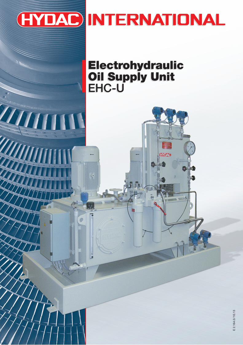
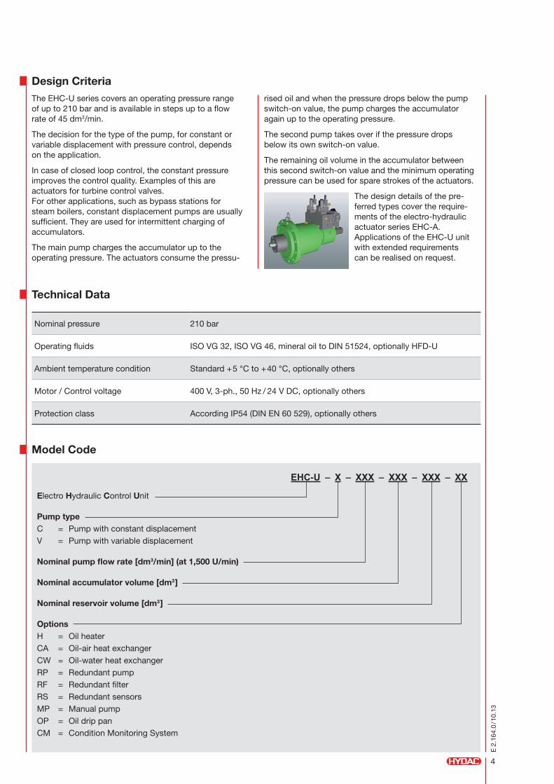
The picture shows a photo of an EHC-U unit with additional special equipment.
4
E 2
.164
.0/1
0.13
EHC-U – X – XXX – XXX – XXX – XX
Electro Hydraulic Control Unit
Pump type C = Pump with constant displacement V = Pump with variable displacement
Nominal pump flow rate [dm3/min] (at 1,500 U/min)
Nominal accumulator volume [dm3]
Nominal reservoir volume [dm3]
Options H = Oil heater CA = Oil-air heat exchanger CW = Oil-water heat exchanger RP = Redundant pump RF = Redundant filter RS = Redundant sensors MP = Manual pump OP = Oil drip pan CM = Condition Monitoring System
Model Code
Nominal pressure 210 bar
Operating fluids ISO VG 32, ISO VG 46, mineral oil to DIN 51524, optionally HFD-U
Ambient temperature condition Standard +5 °C to +40 °C, optionally others
Motor / Control voltage 400 V, 3-ph., 50 Hz / 24 V DC, optionally others
Protection class According IP54 (DIN EN 60 529), optionally others
Design Criteria
Technical Data
The EHC-U series covers an operating pressure range of up to 210 bar and is available in steps up to a flow rate of 45 dm3/min.
The decision for the type of the pump, for constant or variable displacement with pressure control, depends on the application.
In case of closed loop control, the constant pressure improves the control quality. Examples of this are actuators for turbine control valves. For other applications, such as bypass stations for steam boilers, constant displacement pumps are usually sufficient. They are used for intermittent charging of accumulators.
The main pump charges the accumulator up to the operating pressure. The actuators consume the pressu-
rised oil and when the pressure drops below the pump switch-on value, the pump charges the accumulator again up to the operating pressure.
The second pump takes over if the pressure drops below its own switch-on value.
The remaining oil volume in the accumulator between this second switch-on value and the minimum operating pressure can be used for spare strokes of the actuators.
The design details of the pre- ferred types cover the require-ments of the electro-hydraulic actuator series EHC-A. Applications of the EHC-U unit with extended requirements can be realised on request.
5
E 2
.164
.0/1
0.13
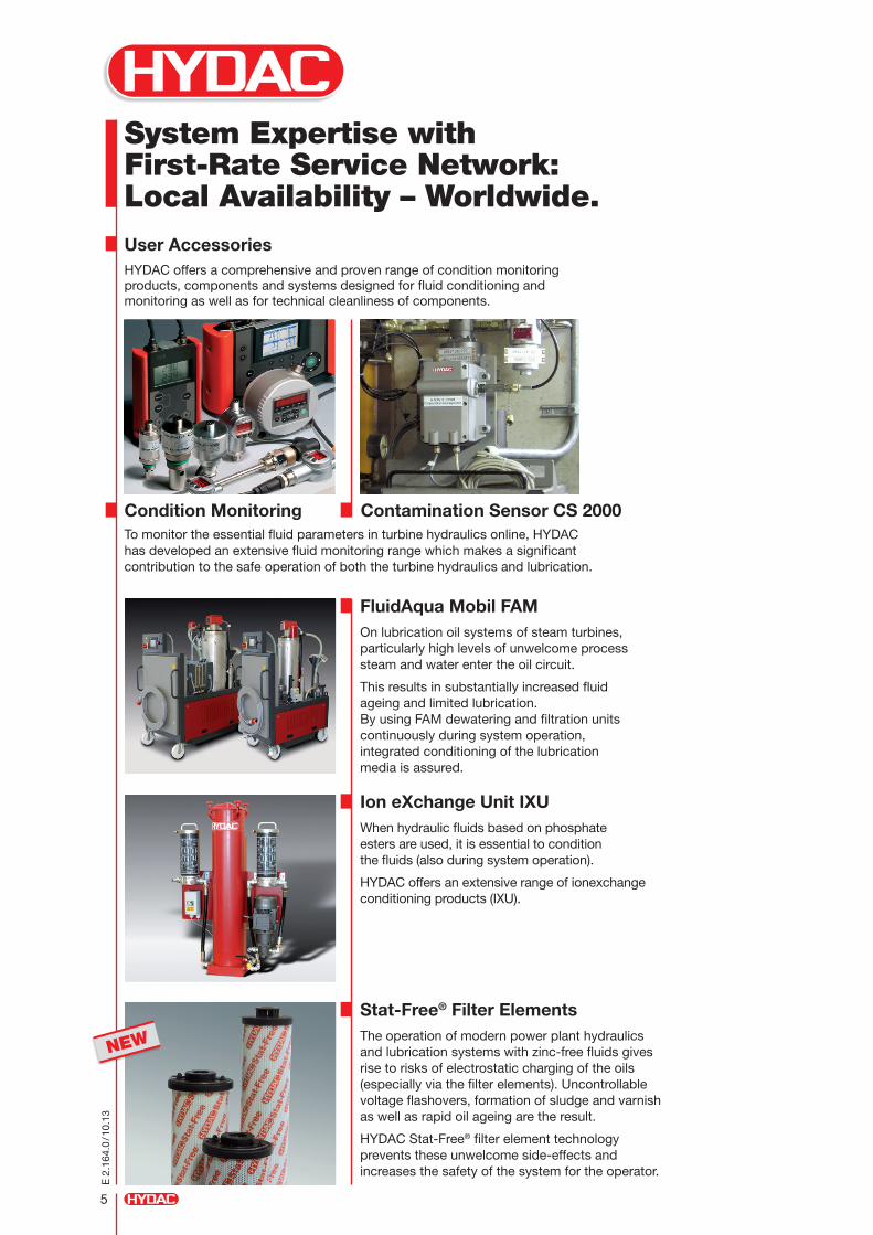
System Expertise with First-Rate Service Network: Local Availability – Worldwide.User AccessoriesHYDAC offers a comprehensive and proven range of condition monitoring products, components and systems designed for fluid conditioning and monitoring as well as for technical cleanliness of components.
Condition Monitoring Contamination Sensor CS 2000To monitor the essential fluid parameters in turbine hydraulics online, HYDAC has developed an extensive fluid monitoring range which makes a significant contribution to the safe operation of both the turbine hydraulics and lubrication.
FluidAqua Mobil FAMOn lubrication oil systems of steam turbines, particularly high levels of unwelcome process steam and water enter the oil circuit.
This results in substantially increased fluid ageing and limited lubrication. By using FAM dewatering and filtration units continuously during system operation, integrated conditioning of the lubrication media is assured.
Ion eXchange Unit IXUWhen hydraulic fluids based on phosphate esters are used, it is essential to condition the fluids (also during system operation).
HYDAC offers an extensive range of ionexchange conditioning products (IXU).
Stat-Free® Filter ElementsThe operation of modern power plant hydraulics and lubrication systems with zinc-free fluids gives rise to risks of electrostatic charging of the oils (especially via the filter elements). Uncontrollable voltage flashovers, formation of sludge and varnish as well as rapid oil ageing are the result.
HYDAC Stat-Free® filter element technology prevents these unwelcome side-effects and increases the safety of the system for the operator.
NEW
E 2
.164
.0/1
0.13
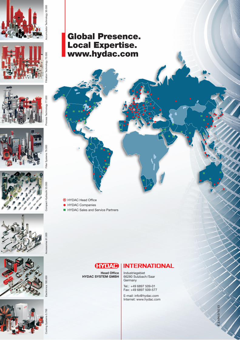
HYDAC Head Office
HYDAC Companies
HYDAC Sales and Service Partners
Global Presence. Local Expertise. www.hydac.com
Industriegebiet 66280 Sulzbach/Saar Germany
Tel.: +49 6897 509-01 Fax: +49 6897 509-577
E-mail: [email protected] Internet: www.hydac.com
Head Office HYDAC SYSTEM GMBH
Coo
ling
Sys
tem
s 5.
700
Ele
ctro
nics
180
.000
Acc
esso
ries
61.0
00C
omp
act-
Hyd
raul
ik 5
3.00
0Fi
lter
Sys
tem
s 79
.000
Pro
cess
Tec
hnol
ogy
77.0
00Fi
ltrat
ion
Tech
nolo
gy 7
0.00
0A
ccum
ulat
or T
echn
olog
y 30
.000