Eléctrodos modificados com polioxotungstatos do Mesquita ... · nitrito, bromato e/ou iodato. A...
184
Universidade de Aveiro 2010 Departamento de Química Diana Mónica de Mesquita Sousa Fernandes Eléctrodos modificados com polioxotungstatos do tipo Keggin Modified electrodes with Keggin-type polyoxotungstates
Transcript of Eléctrodos modificados com polioxotungstatos do Mesquita ... · nitrito, bromato e/ou iodato. A...

Universidade de Aveiro 2010
Departamento de Química
Diana Mónica de Mesquita Sousa Fernandes
Eléctrodos modificados com polioxotungstatos do tipo Keggin Modified electrodes with Keggin-type polyoxotungstates

Universidade de Aveiro
2010
Departamento de Química
Diana Mónica de Mesquita Sousa Fernandes
Eléctrodos modificados com polioxotungstatos do tipo Keggin Modified electrodes with Keggin-type polyoxotungstates
Tese apresentada à Universidade de Aveiro para cumprimento dos requisitos necessários à obtenção do grau de Doutor em Química, realizada sob a orientação científica da Doutora Ana Maria V. S. Viana Cavaleiro, Professora Catedrática do Departamento de Química da Universidade de Aveiro e do Doutor Christopher Michael Ashton Brett, Professor Catedrático da Universidade de Coimbra
Apoio financeiro do POCTI no âmbito do III Quadro Comunitário de Apoio.
Apoio financeiro da FCT e do FSE no âmbito do III Quadro Comunitário de Apoio.

Dedico este trabalho à minha orientadora Doutora Helena Carapuça (1965-2008) pela sua inspiração, apoio incansável e constante amizade.

o júri
presidente Prof. Doutor Casimiro Adrião Pio professor catedrático da Universidade de Aveiro
Prof. Doutora Ana Maria Vieira da Silva Cavaleiro professora catedrática da Universidade de Aveiro
Prof. Doutor Christopher Michael Ashton Brett professor catedrático da Faculdade de Ciências e Tecnologia da Universidade de Coimbra
Prof. Doutor Baltazar Manuel Romão de Castro professor catedrático da Faculdade de Ciências da Universidade do Porto
Prof. Doutora Maria Isabel da Silva Pereira professora associada com agregação da Faculdade de Ciências da Universidade de Lisboa
Prof. Doutora Helena Isabel Seguro Nogueira
professora auxiliar da Universidade de Aveiro

agradecimentos
No final desta etapa não posso deixar de agradecer o meu sincero agradecimento às pessoas que, directa ou indirectamente, contribuíram para a concretização desta investigação. Aos meus orientadores científicos, Doutora Helena Carapuça, Doutora Ana Cavaleiro e Doutor Christopher Brett, muito obrigada por tudo o que me ensinaram, pela dedicação, disponibilidade, incentivo e por toda a amizade e simpatia ao longo destes anos. À Universidade de Aveiro, em particular ao CICECO e ao Departamento de Química, por me terem disponibilizado todas as condições necessárias à realização deste trabalho. À Fundação para a Ciência e a Tecnologia pela bolsa de Doutoramento. À Drª Celeste Azevedo pela realização das análises térmicas e pela simpatia sempre demonstrada. Obrigada aos amigos e colegas do DQ pelo companheirismo, amizade e carinho em especial ao João Rodrigues, à Joana Marques e à Violeta Girão. Obrigada aos colegas e amigos de Coimbra por me terem recebido com tanta simpatia e em especial à Madi por todo o apoio com os estudos de impedância. À Mestre Susana Simões pelo apoio no laboratório, pelas nossas conversas científicas e por toda a amizade demonstrada. Aos meus amigos Nélio, Pedro, Tana, Paula e Jorge muito obrigada por estarem sempre presentes apesar da distância. Às minhas meninas, Luciana Rocha, Patrícia Silva, Diana Lima e Catarina Coelho muito obrigada pela amizade incondicional, carinho e pelo amparo nos momentos mais difíceis. Aveiro não seria a mesma se não vos tivesse conhecido. Ao Renato pelo carinho, compreensão e muita paciência. Aos meus avós João e Isolina, à minha querida irmã Xaninha e em especial aos meus pais José e Fernanda pelo amor constante, pela confiança e por estarem sempre presentes e me apoiarem em todos os momentos da minha vida.

palavras-chave
Polioxotungstatos do tipo Keggin, eléctrodos modificados, voltametria cíclica, espectroscopia de impedância electroquímica.
resumo
O objectivo deste trabalho é a produção de novos eléctrodos modificados com polioxotungstatos (POMs) do tipo Keggin, incluindo POMs lacunares e substituídos por metais de transição. A preparação e caracterização dos polioxotungstatos encontram-se descritas no Capítulo 2. No Capítulo 3 descreve-se a produção de eléctrodos de carbono vítreo funcionalizados com sais híbridos de tetra-n-butilamónio de vários silicotungstatos pelo método de evaporação da gota. As propriedades electroquímicas dos polioxotungstatos imobilizados foram comparadas com as das espécies solúveis correspondentes. A morfologia dos depósitos foi avaliada por microscopia óptica e por microscopia electrónica de varrimento. No capítulo 4 descreve-se a preparação de novos eléctrodos compósitos de carbono e poli(hexilmetacrilato) com fosfotungstatos. Os estudos electroquímicos revelaram que as principais características dos POMs são mantidas e que os processos de redução são controlados por difusão, dependendo da difusão dos protões da solução. O Capítulo 5 descreve a construção de filmes em multicamadas ultrafinos contendo POMs e polietilenimina, preparados pelo método de auto-montagem camada-sobre-camada em eléctrodos de carbono vítreo. Os filmes em multicamada foram caracterizados por voltametria cíclica e por microscopia electrónica de varrimento e foi usada a espectroscopia de absorção de UV-Vis em placas de quartzo para monitorar o crescimento de filme. Os resultados voltamétricos revelaram que os processos de redução dos POM são confinados à superfície. Alguns destes eléctrodos modificados revelaram propriedades electrocatalíticas relativamente à redução dos aniões nitrito, bromato e/ou iodato. A espectroscopia de impedância electroquímica também foi usada na caracterização destes filmes e os resultados revelaram que a resistência à transferência de carga aumenta com o aumento do número de bicamadas para ambas as espécies redox, indicando que a espessura do filme tem um efeito importante sobre a cinética de reacções de transferência de carga. No capítulo 6 descreve-se a síntese de filmes híbridos orgânicos/inorgânicos compostos por poli(3,4-etilenodioxitiofeno) (PEDOT) e por silicotungstatos do tipo Keggin através da polimerização electroquímica, em condições aquosas, na superfície de electrodos de carbono vítreo. A voltametria cíclica revelou que as características principais dos POMs são mantidas nos filmes. Verificou-se que estes filmes são muito estáveis, possivelmente devido a fortes interacções electrostáticas entre os POMs aniónicos e o polímero positivamente carregado. A espectroscopia de impedância electroquímica foi também utilizada e os resultados mostraram que a resistência de transferência de carga aumenta com o aumento do pH e para valores de potenciais mais elevados. O capítulo 7 apresenta as conclusões finais e possíveis trabalhos futuros.

keywords
α-Keggin type polyoxotungstates, modified electrodes, cyclic voltammetry, electrochemical impedance spectroscopy.
abstract
The aim of the present work is the fabrication of novel modified electrodes with Keggin-type polyoxotungstates (POMs), including lacunary and transition metal-substituted POMs. The preparation and characterization of the polyoxotungstates is described in Chapter 2. In Chapter 3 is described the production of glassy carbon electrodes functionalised with tetra-n-butylammonium hybrid salts of several silicotungstate anions by the droplet evaporation method. The electrochemical features of immobilized polyoxotungstates were compared with those of corresponding soluble species. The morphology of the deposits was evaluated by optical and scanning electron microscopy. In Chapter 4 is described the preparation of novel poly(hexylmethacrylate) carbon composite electrodes with phosphotungstates. The electrochemical studies showed that the main features of the POMs are maintained and that the reduction processes are diffusion-controlled, depending on the uptake of protons from the solution. Chapter 5 describes the construction of ultrathin multilayer films containing POMs and poly(ethylenimine) prepared by the electrostatic layer-by-layer self-assembly method on glassy carbon electrodes. The multilayer films were characterized by cyclic voltammetry and scanning electron microscopy, and UV-Vis absorption spectroscopy on a quartz slide was used to monitor film growth. Voltammetric results revealed that the POMs tungsten reduction processes are surface-confined. Some of these modified electrodes showed electrocatalytic properties towards the reduction of nitrite, bromate and/or iodate. Electrochemical impedance spectroscopy (EIS) was also used and showed that the charge transfer resistance increases with increasing number of bilayers for both redox probes indicating that the thickness of the multilayer film has an important effect on the kinetics of the charge transfer reactions. In Chapter 6 is described the synthesis of hybrid organic/inorganic films composed of poly(3,4-ethylenedioxythiophene) (PEDOT) and silicotungstates by electrochemical polymerization under aqueous conditions on the surface of glassy carbon electrodes. Cyclic voltammetry showed that the main features of POMs are maintained in the films. The films presented high stability, possibly due tostrong electrostatic interactions between anionic POM and positively charged polymer. Electrochemical impedance spectroscopy was also used and the results showed that the charge transfer resistance increased with increasing pH and for higher values of potentials used. Conclusions and future perspectives are indicated in Chapter 7.


i
General Index GENERAL INDEX I
PUBLICATIONS LIST V
ABBREVIATIONS LIST VI
SYMBOLS LIST VII
FIGURE INDEX VIII
TABLE INDEX XIII
CHAPTER 1 1
INTRODUCTION 1
1.1. Polyoxometalates 3
1.1.1. Structure of Keggin anions 4
1.1.2. Derivatives of the Keggin anion and related heteropolyoxometalates 7
1.1.3. Properties and applications 9
1.2. Electrochemical behaviour of polyoxometalates 10
1.2.1. Keggin and lacunary anions 11
1.2.2. Mono-substituted Keggin anions 13
1.3. Electrode modification using polyoxometalates 15
1.3.1. Electrochemical polymerization 16
1.3.2. Layer-by-layer Method 21
1.3.3. Carbon Paste Electrodes 24
1.4. Electrochemical techniques 25
1.4.1. Cyclic voltammetry 25
1.4.2. Electrochemical impedance spectroscopy 27
1.5. Scope of the work 32
1.6. References 34
CHAPTER 2 41
POLYOXOMETALATES: SYNTHESIS AND CHARACTERIZATION 41
2.1. Introduction 43

ii
2.2. Experimental 46
2.2.1. Reagents 46
2.2.2. Instrumentation and methods 46
2.2.3. Synthesis 46
2.2.3.1. Synthesis of TBA4H4[SiW11O39] 47
2.2.3.2. Synthesis of TBA4Hx[SiW11M(H2O)O39]·nH2O, M = CoII, Fe
III 47
2.3. Potassium salts of lacunary and mono-substituted anions 48
2.4. Tetra-butylammonium salts of lacunary and mono-substituted anions 52
2.5. Conclusions 56
2.6. References 57
CHAPTER 3 59
FUNCIONALISATION OF GLASSY CARBON ELECTRODES WITH TETRA-BUTYLAMMONIUM SALTS
OF KEGGIN-TYPE SILICOTUNGSTATES 59
3.1. Introduction 61
3.2. Experimental 62
3.2.1. Reagents and solutions 62
3.2.2. Instrumentation and methods 62
3.2.3. Preparation of the modified electrodes and voltammetric procedures 63
3.3. Voltammetric behaviour of lacunary and metal-substituted silicotungstate anions in
aqueous media 64
3.4. Voltammetric behaviour of the hybrid TBA-silicotungstate modified electrodes in acidic
media 68
3.4.1. Effect of scan rate and pH 69
3.4.2. Morphological aspects 73
3.3.2.3. Application of the TBA-SiW11Fe modified electrode in the reduction of nitrite 79
3.5. Conclusions 82
3.6. References 84
CHAPTER 4 85
NOVEL POLY(HEXYLMETHACRYLATE) COMPOSITE CARBON ELECTRODES MODIFIED WITH TBA
SALTS OF KEGGINPHOSPHOTUNGSTATES 85

iii
4.1. Introduction 87
4.2. Experimental 88
4.2.1. Reagents and solutions 88
4.2.2. Instrumentation and methods 88
4.2.3. Preparation of the unmodified and modified CPEs 89
4.3. Characterization of carbon paste electrodes CPE1 and CPE2 90
4.4. Voltammetric behaviour of POM-CPE1 and POM-CPE2 92
4.5. Stability and surface renewal of POM modified CPEs 96
4.6. Conclusions 97
4.7. References 99
CHAPTER 5 101
SELF-ASSEMBLY MULTILAYER FILMS BASED ON KEGGIN-TYPE POLYOXOTUNGSTATES AND
POLY(ETHYLENIMINE) 101
5.1. Introduction 103
5.2. Experimental 104
5.2.1. Reagents and solutions 104
5.2.2. Instrumentation and methods 105
5.2.3. Preparation of self-assembly (PEI/POM)n films 106
5.3. Film formation 106
5.4. Characterization of multilayer (PEI/POM)n films deposited on quartz slides 107
5.5. Scanning electron microscopy characterization 111
5.6. Voltammetric behaviour of multilayer films 113
5.7. Permeability of multilayer films 120
5.8. Electrochemical impedance characterisation 124
5.9. Electrocatalytic properties of (PEI/POM) multilayer films 130
5.10. Conclusions 135
5.11. References 137
CHAPTER 6 139
MODIFIED ELECTRODES WITH SILICOTUNGSTATES AND PEDOT 139
6.1. Introduction 141

iv
6.2. Experimental 142
6.2.1. Reagents and solutions 142
6.2.2. Instrumentation and methods 143
6.2.3. Preparation of POM doped PEDOT films 143
6.3. Cyclic voltammetry of the POM doped PEDOT films 143
6.3.1. Film formation and stability 143
6.3.2. Film characterisation 147
6.4. Electrochemical impedance spectroscopy of the POM doped PEDOT films 151
6.5. Conclusions 154
6.6. References 155
CHAPTER 7 157
CONCLUSIONS 157

v
Publications List
1. Diana M. Fernandes , Susana M. N. Simões, Helena M. Carapuça, Ana M. V.
Cavaleiro, “Functionalisation of glassy carbon electrodes with adsorbed tetra-
butylammonium microcrystalline salts of lacunary and metal substituted α-Keggin-
polyoxosilicotungstates”, Electrochimica Acta 53 (2008) 6580.
2. Diana M. Fernandes , Susana M. N. Simões, Helena M. Carapuça, Christopher M. A.
Brett, Ana M. V. Cavaleiro, “Novel poly(hexylmethacrylate) composite carbon electrodes
modified with Keggin-type tungstophosphate tetra-butylammonium salts”, Journal of
Electroanalytical Chemistry 639 (2010) 83.
3. Diana M. Fernandes , Helena M. Carapuça, Christopher M. A. Brett, Ana M. V.
Cavaleiro, “Electrochemical behaviour of self–assembly multilayer films based on iron–
substituted α–Keggin polyoxotungstates, Thin Solid Films 518 (2010) 5881.
4. Diana M. Fernandes , Christopher M. A. Brett, Ana M. V. Cavaleiro, “ Layer-by-Layer
self-assembly and electrocatalytic properties of poly(ethylenimine)-silicotungstate
multilayer composite films”, Journal of Solid State Electrochemistry, DOI 10.1007/s10008-
010-1154-1 (in press).
5. Diana M. Fernandes , Mariana E. Ghica, Christopher M. A. Brett, Ana M. V. Cavaleiro,
“Electrochemical impedance study of layer-by-layer iron-silicotunsgtate/
poly(ethylenimine) modified electrodes”, submitted in Electrochimica Acta.
6. Diana M. Fernandes , Christopher M. A. Brett, Ana M. V. Cavaleiro, “Preparation and
electrochemical properties of modified electrodes with Keggin-type silicotungstates and
PEDOT”, submitted in Journal of Electroanalytical Chemistry.

vi
Abbreviations List COP Conducting organic polymers
CPEs Carbon paste electrodes
CV Cyclic voltammetry
DMF Dimethylformamide
DMSO Dimethylsulfoxide
EIS Electrochemical impedance spectroscopy
GCE Glassy carbon electrode
ITO Indium tin oxide
IUPAC International Union of Pure and Applied Chemistry
LbL Layer-by-layer
MCM Mobil composition of matter
NMR Nuclear magnetic resonance
PAni Polyaniline
PDDA Poly(diallyldimethylammonium chloride)
PEDOT Poly(ethylenedioxythiophene)
PEI Poly(ethylenimine)
POMs Polyoxometalates
PPy Polypyrrole
PT Polythiophene
SEM Scanning electron microscopy
TBA Tetra-n-butylammonium [N(C4H9)4]+
TG Thermogravimetry
UV-Vis Ultraviolet-visible
XW11 Lacunary anion [XW11O39](n+4)-, X = P, Si, etc
XW11M Mono-substituted anion [XW11M(H2O)O39]m-, X = P, Si, and M = Fe, Co, Mn,
etc
XW12 Keggin anion [XW12O40]n-, X = P, Si, etc

vii
Symbols List A Geometric area of the electrode
Aλ Absorbance at specific wavelength
C Capacitance
Cd Double layer capacity
CPE Constant phase element
E1/2 Mid wave potential
Epa Anodic peak potential
Epc Cathodic peak potential
F Faraday's constant
Ipa Anodic peak current
Ipc Cathodic peak current
n Number of electrons transferred
Rct Charge transfer resistance
RΩ Cell resistance
T Temperature
ZW Warburg element
Γ Surface coverage
∆Ep Peak-to-peak separation
ελ Isotropic molar absorption coefficients
ν Scan rate
viii
Figure Index
Chapter 1
Figure 1.1. Representation of the α-Keggin polyanion structure. (a) Ball and stick structure
(the central yellow ball represents the heteroatom X, the green balls are the addenda atoms
and the red ones the oxygen atoms, (b) Polyhedral representation with indication of the
different types of oxygens in the structure.__________________________________________ 5
Figure 1.2. The five Baker-Figgis isomers of the Keggin structure (α isomer). In the β, γ, δ and
ε structures, one, two, three and four M3O13 groups have been rotated by 60°._____________ 6
Figure 1.3. Polyhedral representation of the (a) α-Keggin anion, (b) lacunary anion and (c)
mono substituted anion.________________________________________________________ 7
Figure 1.4. Polyhedral representation of the (a) sandwich anion, (b) Dawson anion._________ 8
Figure 1.5. Structures of conducting polymers, from top to bottom: poly(para)phenylene,
polypyrrole, polythiophene and polyaniline._________________________________________ 17
Figure 1.6. Examples of polythiophenes: (a) poly(thiophene-2,5-diyl), PTh and (b)
poly(ethylenedioxythiophene), PEDOT.____________________________________________ 19
Figure 1.7. Mechanism of electropolymerization of heterocycles.________________________ 20
Figure 1.8. Scheme of the electrostatic layer-by-layer self-assembly of oppositely charged
polyelectrolytes.______________________________________________________________ 21
Figure 1.9. Example of standard polyelectrolytes used in layer-by-layer method: (a)
poly(acrylic acid), (b) poly(vinylsulfate), (c) poly(allylamine), (d) poly(diallyldimethylammonium
chloride), (e) poly(styrene sulfonate) and (f) poly(ethyleneimine).________________________ 22
Figure 1.10. Cyclic voltammogram for a reversible system: 1 mM K3[Fe(CN)6] + 1 M KCl, scan
rate 20 mV s-1._______________________________________________________________ 26
Figure 1.11. Equivalent electric circuit of an electrochemical cell for a simple electrode
process.____________________________________________________________________ 29
Figure 1.12. Complete Randles type equivalent electric circuit. The circuit comprises a cell
resistance RΩ, in series with a parallel combination of a double layer capacity, Cd, and a
charge transfer resistance, Rct, together with a Warburg impedance, Zw.__________________ 30
Figure 1.13. Complex plane impedance plot for a simple electrochemical system:
O + ne- → R.________________________________________________________________ 31

ix
Chapter 2
Figure 2.1. Infrared spectrum of the K5[SiW11FeIII(H2O)O39]·13H2O salt.__________________ 49
Figure 2.2. Thermogram of the K8[SiW11O39]·13H2O salt._____________________________ 51
Figure 2.3. Infrared spectrum of the TBA4H4[SiW11O39] salt.___________________________ 53
Figure 2.4. Thermogram of the TBA4H3[PW11O39] salt._______________________________ 55
Chapter 3
Figure 3.1. Cyclic voltammograms of K+ salts (1 mM), in pH 2.0 buffer solution (H2SO4 / HAc /
NaAc), ν = 50 mV s-1: (a) SiW11, (b) SiW11Fe and (c) SiW11Co. Also shown are the partial
voltammograms for the first pair of W peaks and for the iron pair of peaks in SiW11Fe (bold
lines). Arrows represent the oxidation peaks for β-isomers.____________________________ 65
Figure 3.2. Plots of: (a) lg Ipc versus lg ν in pH = 2.0 buffer solution (H2SO4 / HAc / NaAc) and
(b) Epc versus pH in buffer solutions, ν = 50 mV s-1.__________________________________ 67
Figure 3.3. Cyclic voltammograms for immobilized TBA-polyanions on GCE immersed in pH
2.0 buffer solution (H2SO4 / HAc / NaAc), ν = 50 mV s-1: (a) SiW11, (b) SiW11Fe and (c)
SiW11Co. Also shown are the partial voltammograms for the first pair of W peaks (bold lines)._ 70
Figure 3.4. Cyclic voltammograms for TBA-SiW11Fe modified electrode in pH 2.0 buffer
solution (H2SO4 / HAc / NaAc) at different scan rates (10, 25, 50, 75, 100 and 250 mV s-1).___ 71
Figure 3.5. Typical optical micrographs for a TBA-SiW11-GCE. (A) General view of the
electrode surface: × 5 magnification. (B) Crystallites on the electrode surface: × 50
magnification._______________________________________________________________ 73
Figure 3.6. Typical optical micrographs for a TBA-SiW11Fe-GCE. (A) General view of the
electrode surface: × 5 magnification. (B) Crystallites on the electrode surface: × 100
magnification (under polarized light).______________________________________________ 74
Figure 3.7. Typical SEM micrographs for a: (A) TBA-SiW11-GCE, (B) TBA-SiW11Fe-GCE and
(C) TBA-SiW11Co-GCE salts (all micrographs were acquired at the same x30 magnification)._ 75
Figure 3.8. Typical SEM micrographs for TBA-POM salts deposited on GCE._____________ 76
Figure 3.9. Typical SEM micrographs for solid TBA-POM salts.________________________ 77
Figure 3.10. Cyclic voltammograms for immobilized TBA- SiW11Fe on the GCE (same
conditions as in Fig. 3.3), (a) first; (b) second and (c) sixth working day.__________________ 79
Figure 3.11. Catalytic activity of the immobilised TBA- SiW11Fe in the presence of different
amounts of nitrite. Cyclic voltammograms obtained in the absence and in the presence of
increasing concentrations of nitrite, in the interval [0 - 0.09 mM]: a) 0; b) 0.01; c) 0.04 and d)
0.09 mM. Inset: representation of the catalytic peak current at -0.6 V vs. the concentration of
nitrite. Experimental conditions: pH 2.0 buffer solution (H2SO4/HAc/NaAc), ν= 20 mV s-1._____ 80

x
Figure 3.12. Catalytic activity of the water soluble K-SiW11Fe anion in the presence of
different amounts of nitrite in aqueous solution. Cyclic voltammograms obtained in the
absence and in the presence of increasing concentrations of nitrite, in the interval [0 – 3.00
mM]: a) 0; b) 1.00; c) 2.00 and d) 3.00 mM. Inset: representation of the catalytic peak current
at -0.6 V vs. the concentration of nitrite. Experimental conditions: pH 2.0 buffer solution
(H2SO4/HAc/NaAc), ν= 20 mV s-1.________________________________________________ 81
Chapter 4
Figure 4.1. Schematic representation indicating the components used in electrode
preparation._________________________________________________________________ 90
Figure 4.2. Cyclic voltammograms of (a) CPE1 and CPE2 in 1 M KCl electrolyte and, (b) CPE1
and (c) CPE2 in a solution of 1 mM K3[Fe(CN)6] + 1 M KCl. Scan rate 20 mV s-1.___________ 91
Figure 4.3. Plot of lg Ipc versus lg ν for () CPE1 and () CPE2 in a solution of 1 mM
K3[Fe(CN)6] + 1 M KCl.________________________________________________________ 92
Figure 4.4. Cyclic voltammograms for PW11Co-CPE2 immersed in pH 2.0 H2SO4/ HAc / NaAc
aqueous solution at ν=50 mV s-1, inverting the scan direction after the first reduction peak (---)
and after the second reduction peak (―).__________________________________________ 93
Figure 4.5. Cyclic voltammograms for (a) PW11-CPE1, and (b) PW11-CPE2, immersed in pH
2.0 buffer solution (H2SO4 / HAc / NaAc) at scan rates 20, 50, 100, 500, 750 and 1000 mV s-1. 94
Figure 4.6. Cyclic voltammograms for PW11-CPE2 immersed in pH 2.0 buffer solution (H2SO4/
HAc / NaAc), ν = 50 mV s-1: (a) first (b) second working day; (c) after one week.___________ 97
Chapter 5
Figure 5.1. Schematic diagram of the formation of the multilayer structure via alternate
adsorption of cationic PEI and anionic POM on a substrate.__________________________ 107
Figure 5.2. UV-Vis absorption spectra of (a) (PEI/PW11Fe)n and (b) (PEI/SiW11Fe)n
multilayers for n = 0 – 8 adsorbed on a quartz slide. The insets in (a) and (b) show the
absorbance at (a) 260 nm and (b) 258 nm, as a function of n. The inset in (b) also shows the
absorbance as a function of n for different deposition times: () 20, (∆) 10 and (◊) 5 min.____ 108
Figure 5.3. UV-Vis absorption spectra of (a) (PEI/SiW11)n and (b) (PEI/SiW11Co)n multilayers
for n = 0 – 7 adsorbed on a quartz slide. The insets in (a) and (b) show the absorbance at (a)
248 nm and (b) 254 nm, as a function of n.________________________________________ 109
Figure 5.4. Typical SEM micrographs for a PEI layer adsorbed on a glassy carbon electrode. 111
Figure 5.5. Representative SEM micrographs of (PEI/SiW11Co)2, (PEI/PW11Fe)2 and
(PEI/SiW11Fe)2 films on a glassy carbon electrode at different magnifications. ____________ 112

xi
Figure 5.6. Cyclic voltammograms in CH3COOH/NaCH3COO buffer solution (pH 4.0) at
different scan rates: 25, 50, 75, 100, 125, 150, 200, 250 and 300 mV s-1 for (a) (PEI/SiW11)1
and (b) (PEI/SiW11Co)1 bilayer films._____________________________________________ 114
Figure 5.7. Cyclic voltammograms for (PEI/POM) bilayer films in CH3COOH/NaCH3COO
buffer solution (pH 4.0) at different scan rates: (a) 25, 50, 75, 100, 125, 150, 200 and 250 mV
s-1 for (PEI/SiW11Fe) and (b)10, 25, 50, 75 and 100 mV s-1 for (PEI/PW11Fe)._____________ 115
Figure 5.8. Cyclic voltammograms for (a) (PEI/SiW11)n and (b) (PEI/SiW11Co)n multilayer
films in CH3COOH/NaCH3COO buffer solution (pH 4.0) for n = 1 – 7, ν = 50 mV s-1. The
insets show the peak currents vs. the number of multilayers.__________________________ 117
Figure 5.9. Cyclic voltammograms for (a) (PEI/SiW11Fe)n and (b) (PEI/PW11Fe) multilayer
films in CH3COOH/NaCH3COO buffer solution (pH 4.0) for n = 6 for PEI/SiW11Fe and 7 for
PEI/PW11Fe, ν = 10 mV s-1. The insets show the peak currents vs. the number of
multilayers.________________________________________________________________ 118
Figure 5.10. Cyclic voltammograms of [Fe(CN)6]3-/4- (1 mM, 1 M KCl) ν = 100 mV s-1, at
modified electrodes with (a) (PEI/SiW11Co)n for (1) n = 1; (2) 2; (3) 4 and (4) 6; (b) 1 -
(PEI/SiW11Co)6 and 2 - (PEI/SiW11Co)6/PEI._______________________________________ 122
Figure 5.11. Cyclic voltammograms of [Ru(NH3)6]3+/2+ (1 mM, 1 M KCl) ν = 100 mV s-1, at
modified electrodes with (a) (PEI/SiW11Co)n for (1) n = 1; (2) 2 and (3) 4; (b) 1 -
(PEI/SiW11Co)1 and 2 - (PEI/SiW11Co)1/PEI._______________________________________ 123
Figure 5.12. Cyclic voltammograms for (PEI/SiW11Co)7 multilayer films in CH3COOH/
NaCH3COO buffer solution (pH 4.0), ν = 25 mV s-1 at first (black), second (red) and eighth
working day (green)._________________________________________________________ 124
Figure 5.13. Complex plane impedance spectra of different modified electrodes in the
presence of 3 mM K3Fe(CN)6 at +250 mV. Lines indicate equivalent circuit fitting._________ 125
Figure 5.14. Complex plane impedance spectra of different modified electrodes in the
presence of 3 mM Ru(NH3)6Cl3 at - 200 mV, with amplitude of 10 mV in the frequency range
from 65 kHz to 0.01 Hz. In the inset a magnification of the spectra is presented. Lines
indicates equivalent circuit fitting._______________________________________________ 126
Figure 5.15. Equivalent electrical circuits used to fit the impedance spectra._____________ 127
Figure 5.16. Complex plane impedance spectra of different ITO modified electrodes in the
presence of 3 mM K3Fe(CN)6 at 250 mV, with amplitude of 10 mV in the frequency range
from 65 kHz to 0.01 Hz. Lines indicate equivalent circuit fitting.________________________ 129
Figure 5.17. Cyclic voltammograms of GCE/(PEI/POM)7 in pH 4.0 buffer solution obtained in
the absence and in the presence of added concentrations of nitrite: (a) SiW11Fe, 1) 0; 2) 0.2;
3) 0.4; 4) 0.5; 5) 0.6 and 6) 0.7 mM, scan rate 10 mV s-1, (b) SiW11Co 1) 0; 2) 0.2; 3) 0.3; 4)
0.5; 5) 0.9 and 6) 1.2 mM, scan rate 25 mV s-1. The inset shows the catalytic peak current at
-0.77 V for SiW11Fe and at -0.90 V vs. the concentration of nitrite for SiW11Co.____________ 132

xii
Figure 5.18. Cyclic voltammograms of GCE/(PEI/SiW11Co)7 in pH 4.0 buffer solution
obtained in the absence and in the presence of added concentrations of (a) bromate: 1) 0; 2)
0.1; 3) 0.3; 4) 0.6 and 5) 1.0 mM, scan rate 50 mV s-1 and (b) iodate: 1) 0; 2) 0.1; 3) 0.2; 4)
0.3; 5) 0.4 and 6) 0.5 mM, scan rate 50 mV s-1. The insets show the catalytic peak current at
-0.90 V vs. analyte concentration._______________________________________________
134
Chapter 6
Figure 6.1. Neutral PEDOT (a) is oxidized to form a conducting polycation (b) in the
presence of charge-balancing anions. Oxidized PEDOT has a transparent sky blue color that
turns dark purple upon reduction._______________________________________________ 144
Figure 6.2. Electropolymerization and formation of hybrid films by potential cycling in 5 mM
EDOT / 0.25 mM SiW11Fe / 0.2 M H2SO4 solution. Potential range -0.75 to 1.1 V; scan rate:
100 mV s-1.________________________________________________________________ 145
Figure 6.3. Cyclic voltammograms for SiW11Fe doped PEDOT obtained in 0.2 M H2SO4
solution, ν = 100 mV s-1: (black) after deposition; (red) end of the first day; (green) six days
later.______________________________________________________________________ 146
Figure 6.4. Cyclic voltammograms for: (a) SiW11Fe-doped PEDOT and (b) PEDOT film.
Electrolyte: 0.2 M H2SO4 solution, ν = 100 mV s-1.__________________________________ 147
Figure 6.5. Cyclic voltammograms of (a) SiW12, (b) SiW11Co and (c) SiW11Fe and doped
PEDOT modified electrodes 0.2 M H2SO4 solution at scan rates of 25, 50, 75, 100, 125, 150,
175, 200,250, 300, 350 and 400 mV s-1.__________________________________________ 148
Figure 6.6. Complex plane impedance spectra of PEDOT/SiW11Fe modified electrode in
H2SO4/Na2SO4 buffer solution (a) pH 2.0, at different applied potentials (b) at -512 mV vs.
Ag/AgCl at different values of pH._______________________________________________ 152
Figure 6.7. Equivalent circuit used to fit the spectra.________________________________ 153

xiii
Table Index
Chapter 2
Table 2.1. List of the polyoxotungstates produced by published methods._______________ 47
Table 2.2. Absorption infrared bands (cm-1) in the spectra of potassium salts of the
[XW11O39]n- and [XW11M(H2O)O39]
m- anions.______________________________________ 50
Table 2.3. Values of wavelength obtained for charge transfer across bridge bonds W-O-W._ 51
Table 2.4. Number of water molecules present in the prepared polyoxotungstates.________ 52
Table 2.5. Absorption infrared bands (cm-1) in the spectra of TBA salts of the lacunary and
metal substituted polyoxotungstates prepared.____________________________________ 54
Chapter 3
Table 3.1. Cyclic voltammetric data for the two W redox processes and for the iron redox
process of the K+ silicotungstate salts at 50 mV s-1 and pH=2.0 buffer solution (H2SO4 / HAc
/ NaAc).__________________________________________________________________ 66
Table 3.2. Cyclic voltammetric data for the adsorbed TBA- silicotungstates on the GCE at
50 mV s-1 and pH=2.0 buffer solution (H2SO4 / HAc / NaAc).__________________________ 72
Chapter 4
Table 4.1. Cyclic voltammetric data for the first W reduction processes in pH 2.0 buffer
solution (H2SO4/HAc/NaAc) at 50 mV s-1.________________________________________ 96
Chapter 5
Table 5.1. Parameters obtained from impedance spectra of the (PEI/POM)n multilayer
assemblies at GCE in the presence of 3 mM [Fe(CN)6]4-/3- and 3 mM [Ru(NH3)6]
2+/3+ redox
probes by fitting to equivalent circuits in Fig. 5.15.__________________________________ 127
Table 5.2. Parameters obtained from impedance spectra of the (PEI/POM)n multilayer
assemblies at ITO electrodes in the presence of 3 mM [Fe(CN)6]4-/3- redox probe by fitting to
the equivalent circuit in Fig. 5.15._______________________________________________ 130

xiv
Chapter 6
Table 6.1. Cyclic voltammetric data of the first W reduction process for silicotungstate doped
PEDOT modified electrodes at 100mV s-1 in 0.2 M H2SO4.___________________________ 150
Table 6.2. Parameters obtained from impedance spectra of the SiW11Fe doped PEDOT
modified electrode in pH 2.0 H2SO4/Na2SO4 buffer solution by fitting to the equivalent circuit
in Fig. 6.7._________________________________________________________________ 153
Table 6.3. Parameters obtained from impedance spectra of the SiW11Fe doped PEDOT
modified electrode at -512 mV in H2SO4/Na2SO4 buffer solutions with different pH values by
fitting to the equivalent circuit in Fig. 6.7._________________________________________ 154

CHAPTER 1
INTRODUCTION
-1.0 -0.8 -0.6 -0.4 -0.2 0.0
1 µA
E (V) vs. Ag/AgCl
-1.0 -0.8 -0.6 -0.4 -0.2 0.0
1 µA
E (V) vs. Ag/AgCl
-1.0 -0.8 -0.6 -0.4 -0.2 0.0
1 µA
E (V) vs. Ag/AgCl
-1.0 -0.8 -0.6 -0.4 -0.2 0.0
1 µA
E (V) vs. Ag/AgCl

Chapter 1
2
INTRODUCTION 1
1.1. Polyoxometalates 3
1.1.1. Structure of Keggin anions 4
1.1.2. Derivatives of the Keggin anion and related heteropolyoxometalates 7
1.1.3. Properties and applications 9
1.2. Electrochemical behaviour of polyoxometalates 10
1.2.1. Keggin and lacunary anions 11
1.2.2. Mono-substituted Keggin anions 13
1.3. Electrode modification using polyoxometalates 15
1.3.1. Electrochemical polymerization 16
1.3.2. Layer-by-layer Method 21
1.3.3. Carbon Paste Electrodes 24
1.4. Electrochemical techniques 25
1.4.1. Cyclic voltammetry 25
1.4.2. Electrochemical impedance spectroscopy 27
1.5. Scope of the work 32
1.6. References 34

Introduction
3
This chapter has the aim of introducing the polyoxometalates (POMs), mainly
Keggin-type polyoxometalates, and their importance and application in the
electrochemistry field. Therefore, first will be given a general introduction to POMs,
presenting what they are and some of their main features, with particular reference to the
Keggin anions and their derivatives. These compounds have been of growing interest
over recent decades, in areas such as catalysis, medicine and materials science due to
their important properties, reactivity, and molecular and electronic versatility. Secondly, an
overview will be given of the electrochemical behaviour of these compounds and on what
has been studied in the field of modified electrodes using polyoxometalates. Finally, the
fundamentals of the main electrochemical techniques used will be presented.
1.1. Polyoxometalates
Polyoxometalates are a set of inorganic clusters in the vast field of coordination
chemistry compounds. They are characterized by metallic centres, M = V, Mo, W (or less
frequently Nb and Ta), called the addenda atoms, surrounded by bridging or terminal
oxygen atoms. Apart from M and O, other elements can be part of the POM cluster. We
can distinguish two types of POM families: the isopolyanions ([MxOy]m-) and the
heteropolyanions ([XzMxOy]n-), where the elements X are the so-called primary
heteroatoms. This heteroatom is essential for the complete polyanion structure, from
where it cannot be removed or chemically substituted without destroying the anion. In
some cases, there are secondary heteroatoms that may in principle, and generally in

Chapter 1
4
practice, be excised from the heteropolyanion structure to leave an independently stable
polyanion [1,2].
The IUPAC nomenclature for POMs proposes names that are normally quite long
and not easily applied, for this reason the more common designations among those who
work in this area will be used in this thesis. In a review article, Jeannin explains how to
connect a name to the structure according to the IUPAC rules [3].
In this work, only the Keggin-type and related heteropolyanions are studied (often
referred as polyanions) and, those where the M element is tungsten (W), so the
polyoxometalates studied are all polyoxotungstates.
1.1.1. Structure of Keggin anions
The increasing diversity of structures classified in the literature as polyoxometalates
turns the definition of this group of compounds gradually more diffuse. This diversity is a
consequence of many and unusual properties of POMs. The vast diversity of polyanions
known present structures, which are usually composed of MO6 octahedra linked together
through oxygen bridges. The strong polarization of the external layer of oxygens (terminal
oxygens) in relation to the interior of the octahedra (due to π bonding), explains why, when
the stage of the heteropolyanion species is reached, by combining MO6, the
polymerization process does not continue, leading to infinite chains, but ends with the
achievement of discrete units [4].
Among the most studied polyoxometalates are the Keggin anions and their
derivatives. The Keggin anion of general formula α-[XM12O40]n-, M = MoVI, WVI; X = PV,
AsV, GeIV, SiIV, BIII, FeIII, CoII, amongst others, has a overall Td symmetry, when M = W and
T symmetry when M = Mo (Fig. 1.1) [1].
The Keggin anion may have more than one type of addenda atom, as in
[PV2W10O40]5- or [SiMo3W9O40]
4-. These are called mixed heteropolyanions.

Introduction
5
Oa
Oc
Od Ob
Figure 1.1. Representation of the α-Keggin polyanion structure. (a) Ball and stick structure (the
central yellow ball represents the heteroatom X, the green balls are the addenda atoms and the red
ones the oxygen atoms, (b) Polyhedral representation with indication of the different types of
oxygen in the structure.
In the Keggin anion, the central XO4 tetrahedron is surrounded by twelve MO6
octahedra arranged in four groups of three edge-shared octahedra, M3O13 [1]. Every M
atom has one terminal oxygen atom. Each MO6 group shares three oxygen atoms inside
the M3O13 group, and two other with the octahedra of neighbouring M3O13 groups. Inside
the same M3O13 group, each metal M shares two oxygen atoms with the two neighbouring
M and the third with the primary heteroatom X. The metal atom M is displaced outwards
from the central position of the octahedra MO6, in the direction of the unshared oxygen. As
a result, four types of oxygen atoms in the structure can be identified (Fig. 1.1):
Oa: oxygen shared between each three octahedra of M3O13 group and with the
XO4 group
Ob: oxygen shared between octahedra of the same M3O13 group
Oc: oxygen shared between octahedra of different M3O13 groups
Od: unshared oxygen from the MO6 group (terminal oxygen).
Although the polyhedral representation may suggest otherwise, the Keggin
structure, like that of most polyanions, is a closed-pack arrangement of oxygen atoms
[1,2,5]. Pope showed that based on metal atom displacement, polyanions can be divided

Chapter 1
6
into two categories: type I, displacement towards one, always terminal, oxygen atom, and
type II, towards two cis, usually but not always, terminal oxygen atoms [1]. The Keggin-
type anions belong to the first category.
The formula of these Keggin polyanions, for M = W, is presented through this thesis
by the abbreviation XW12 (where X = PV and SiIV).
The Keggin anions can present different geometric isomers, β, γ, δ and ε, which
were proposed by Baker and Figgis (Fig. 1.2) and are pointed out as possible structures
related with the Keggin anion (α isomer).
Figure 1.2. The five Baker-Figgis isomers of the Keggin structure (α isomer). In the β, γ, δ and ε
structures, one, two, three and four M3O13 groups have been rotated by 60° [1].
These isomers are related to the Keggin anion by the rotation of 60° of a M 3O13
group relatively to the α isomer. Thus, when one, two, three and four groups are moved,
the geometric isomers, β, γ, δ and ε, are respectively obtained. In fact, although the δ and
ε isomers have never been observed, the β isomer has been recorded for the polyanions
XM12 (X = P, Si, Al and M = W, Mo) and the γ isomer for the [SiW12O40]4- anion [1,6-8].
For heteropolytungstates, in the β isomer, new corner-shared W-O-W linkages
between the rotated group and the rest of the anion involve shorter W...W separations and
more acute W-O-W angles than the α structure. Both of these features may account for
the lower stability of β, compared with α, owing to increased coulombic repulsion (due to
higher proximity of metal centres) and less favourable pπ-dπ interactions (responsible for
the π W-O bond) [1,8,9]. In addition, an increase in the number of octahedra that are
corner-shared can be observed in the sequence α → β → γ → δ → ε, which implies lower
stability of the resulting isomers, due to higher coulombic repulsions [1].
All the polyanions prepared and studied in this work are α isomers and, for this
reason, the prefix α is omitted throughout this thesis.

Introduction
7
1.1.2. Derivatives of the Keggin anion and related heteropolyoxometalates
From the Keggin anion, lacunary species can be obtained by removal of one, or
more, MOx groups. In the mono-lacunary anions this corresponds to the elimination of a
MO4+ group formed by any of the twelve addenda atoms (M) of the Keggin MX12 anion
with its terminal oxygen.
Figure 1.3. Polyhedral representation of the (a) α-Keggin anion, (b) lacunary anion and (c) mono
substituted anion.
In this work, only the mono-lacunary species are used and are represented by the
general formula [XM11O39] (n+4)-. The formula of these polyanions for M = W is presented
several times through this thesis by the abbreviation XW11 (where X = PV and SiIV). This
lacunary species has a lacuna with five oxygen atoms that can potentially coordinate (Fig.
1.3b).
Other isomeric forms of the lacunary anion can be obtained by the removal of an
MO4+ group of the β isomers of the Keggin anion. Only one α isomeric lacunary form
results from the α structure. However, the β isomer can give rise to three isomeric
structures: β1, β2 and β3 that differ from each other in the position of the removed
octahedra. The β1 and β2 correspond to the removal of an MO4+ in the adjacent group to
the rotated W3O13 and β3 refers to the removal of an MO4+ group in the rotated W3O13
group [1].
The lacunary anions react with transition metal ions to form complexes with global
stoichiometry 1:1 (metal:ligand). In these 1:1 complexes, the five oxygen atoms of the
lacunary anion may bind to the metal, with the polyanion ligand functioning, in general, in
a pentadentate manner. The sixth coordination site on the metal in these complexes may
be occupied by a variety of ligands, L, where the more common are H2O, OH-, O2- or an
(a) (b) (c)
- MO4+ MM+- MO4+- MO4+ MM+ MM+

Chapter 1
8
amine [1]. The general formula for the mono-substituted polyanion can therefore be
written as [XM11M'(L)O39] m- (Fig. 1.3c). The metal cation M' must have appropriate
dimensions to occupy the lacuna and to maintain the Keggin structure [1]. Larger ions,
such as lanthanides Ln3+, bind preferentially to two lacunary moieties (tetradentate),
forming complexes with 1:2 (metal:ligand) stoichiometry.
There is a wide variety of mono-substituted heteropolyanions and in some cases the
element that occupies the X and M' positions in the structure is the same (generally FeIII,
CoII, ZnII, AlIII, TiIV and GaIII) [1,2,10]. Other polyanions can also be found in the literature
with a large variety of metal ions in the lacuna, like VIII, CrIII,V, MnII,III,IV, FeII, CoIII, RuII,III,IV,
NiII, CuII, RhIII, PdII, InIII, TlIII, GeIV, SnII,IV, PbII,IV, SbIII,V, IrIV, OsVI, TcV, ReV,VI,VII [1,10,11].
From the Keggin anion, more than one MO4+ group can be removed. For example,
the tri-lacunary [XM9O34] (n+6)- results from the removal of three MO4+ groups from three
different octahedra and from some associated oxygen atoms (fragment M3O66+) of the
Keggin anion. Several isomers are possible [1]. These tri-lacunary anions, like the mono-
lacunary anion, are potentially coordinative, leading to several complexes with transition
metal cations, particularly, tri-substituted anions and sandwich type anions such as, for
example [M'4(H2O)2(PW9O34)2]10- (Fig. 1.4a).
Figure 1.4. Polyhedral representation of the (a) sandwich anion, (b) Dawson anion.
Another type of polyanion related to the Keggin anions are the Dawson anions such
as, for example [P2W18O62] 6- (Fig. 1.4b), that can be envisaged as resulting from two
[PM9O34]9- units fused into a cluster [1]. These types of polyanion are related to mono- and
tri- substituted Dawson anions or to sandwich type polyoxometalates, the parent anion
being of a family of heteropolyanions identical to that of the Keggin anions. These types of
polyanion were not prepared in this work but they are sometimes referred in order to
compare their properties with the Keggin anions used.
(a) (b)
Introduction
9
1.1.3. Properties and applications
Interest in polyoxometalates is increasing worldwide due to their enormous variety of
structures and to their unique set of properties. Their ionic size may be extremely high and
they can reach molar masses of approximately 40000 g mol-1 [12].
These polyanions have different charges depending on the structure and of the type
of elements present. In the crystals, the electrostatic attractions between the
heteropolyanions and the counter-cations have low intensity, due to the increased
distance of mass centres. The fact that the exteriors of the heteropolyanions consist
largely, or entirely, of oxygen atoms that are very strongly polarized toward the addenda,
and, therefore, not polarisable in other directions, creates a condition where one might
expect van der Waals attractions between the complexes to be essentially nonexistent if
they involve species having only exterior oxygen atoms that are adjacent to addenda
atoms only [4]. These two reasons are responsible for low lattice energy of salts
containing heteropolyanions. Given that the complex’s solvation energy for a typical
heteropolyanion is also low, solubility of the salts is essentially given by the type of
counter-cation. Therefore, salts of K+, Na+, NH4+ are water soluble and tetra-
butylammonium salts (TBA) are soluble in organic solvents [4].
For the Keggin-type anions and their derivatives, in particular for the
polyoxotungstates, their interesting properties also include high thermal stability, rich
redox chemistry, photochemical and catalytic features towards a number of industrially
and biologically significant reactions [1,10,13-15]. These compounds are also resistant to
oxidative degradation due to the fact that their fundamental elements (addenda atoms)
are, generally, in their higher oxidation state [1,2,4,16]. These properties make them very
attractive in many fields such as catalysis (including photocatalysis), where they can be
used as acid or oxidative catalysts, in solution or in the solid state, with the possibility of
being applied in heterogeneous or homogeneous catalysis [17]. Other important
application fields are medicine (antitumoral, antiviral and even anti-HIV activity),
electrochemistry, analytical chemistry, materials science and energy storage [1,10,13-
15,18-26]. These fields are the focus of much current and undergoing research. Among
their properties, the ability to undergo reversible multi-electron redox processes makes
them very attractive for chemically modified electrodes and electrocatalysis [1,13,14].
The application of polyoxometalates in the fields mentioned above has been seen
improved with increased interest due to the fact that their synthesis can be carried out in
large quantities and using common reagents with fairly low-price.

Chapter 1
10
1.2. Electrochemical behaviour of polyoxometalates
The study of the electrochemical behaviour of POMs was pioneered by the Souchay
group in the early forties [1], having been retaken in the late sixties by other research
groups [27-31]. Since then, the electrochemical study of these compounds has widened,
especially in homogeneous electrolytic systems. Recently, POMs have been applied in
the preparation of modified electrodes, in which the polyanions are deposited onto the
electrode surface, changing their properties in this way [1,13,29].
A vast number of POMs can undergo a series of reversible reductions of one or two
electrons. The occurrence of reversible reductions can be found for type I
polyoxotungstates where the WO6 octahedra have only one terminal oxygen atom and is
associated with the fact that the electrons added to M enter an orbital that is
predominantly non-bonding, with minimal subsequent bond length alteration. On the other
hand, in the type II polyoxotungstates, the WO6 octahedra have two terminal oxygen
atoms and the added electrons enter an anti-bonding orbital, resulting in large structural
changes [1,13].
The parent, lacunary and mono-substituted Keggin type anions are well studied in
aqueous media, by electrochemical methods such as cyclic voltammetry [4,11,13,32].
Studies with parent and lacunary anions in organic media are also reported in the
literature [33-36]. Nevertheless, studies in organic solution with mono-substituted Keggin
type anions are scarce [37,38]. In aqueous solution, many studies show that pH has a
large influence on the reduction of these polyanions. Generally, there is a linear
dependence between the redox potentials attributed to the reduction of tungsten atoms or
of the transition substituting metal and the pH value, resulting from protonation of the
reduced species [12,31,32,39,40]. The slopes depend on the number of protons and
electrons exchanged in the redox process. When the pH value of the solution is
favourable to protonation, in general more electrons can be transferred to the POM
structure [28].
Polyoxometalates can also contain, in their structure, different transition metal ions
that have different reduction potentials, giving rise to different oxidation-reduction
processes.

Introduction
11
1.2.1. Keggin and lacunary anions
The number of electrons that can be transferred reversibly to the tungsten atoms in
the structure of Keggin type POM is limited. In general, the polyanion structure is not
significantly altered when the number of electrons is lower or equal to four [13]. In these
conditions the “heteropoly blues” (constituted by WVI and WV [41]) are formed. When, six,
or more than six electrons are added to the polyanion structure, brown polyanions are
formed which present structural and electrochemical properties different from the non-
reduced polyanions and from the heteropoly blues. In the brown polyanions (constituted
by WVI and WIV), the electrons added to the structure through successive reductions are
not delocalized in the structure, but originate WIV3O13 groups [1,41].
The redox chemistry of some heteropolyanions, especially of the Keggin complexes,
[XW12O40]n-, have been studied in detail, knowing that these are reduced and re-oxidized
with preservation of their structures [42]. Souchay was the first to study the reduction of
Keggin anions [PW12O40]3-, [SiW12O40]
4-, and [H2W12O40]6-, in aqueous media [43]. These
redox processes are attributed to the reduction and oxidation of tungsten atoms [1].
The partial reduction of polyanions leads to the appearance of an intense blue
colour, the heteropoly blues. These were first described by Berzelius and have been the
base for many analytical procedures [44]. The blue coloration is due to the partial
reduction of the addenda atoms (W, Mo) of the Keggin type polyanions and the intensity
of the colour increases with increasing number of transferred electrons [28,29]. More
specifically, the blue colour is attributed to intervalence electronic transition due to the
existence of addenda atoms in the oxidation state +6 and +5. When an electron enters
the polyanion structure, it is rapidly delocalized through the addenda atoms. When a
second electron is added to the structure, it is also delocalized quickly between the
different addenda atoms. However, the two electrons never meet each other in the same
addenda atom. The electronic delocalization may, or may not, occur in the whole
polyanion structure. However, 183W NMR studies show that the delocalization of electrons,
within the polyanion structure, occurs more easily between addenda atoms of the same
W3O13 group than between different groups, since the distance between tungsten atoms
inside the same W3O13 group is smaller than between different groups [41,45].
The formation of blue heteropolyanions involves a fast and reversible reduction
process, the corresponding cyclic voltammograms being constituted by several reversible
waves. The reduction process progress leads to the disappearance of the blue colour, but

Chapter 1
12
the term blue heteropolyanion may indicate, for some authors, a reduced heteropolyanion,
regardless of its colour [1].
Pope and Varga [13] studied the reduction of [PW12O40]3-, [SiW12O40]
4-, [FeW12O40]5-,
[CoW12O40]6- and [H2W12O40]
6- by polarographic and potentiometric methods, showing that
these anions can undergo two reductions of one electron, without decomposition. In acidic
solutions, these anions can accept more than two electrons, these reductions being
accompanied by protonation, keeping the overall ionic charge at -6. In neutral solutions
(pH > 5) reduction proceeds until the charge of the reduced species is -8 [13]. In the
presence of a higher concentration of protons in solution (lower pH), the two reductions of
one electron are converted in one two electron reduction and it is accompanied by the
addition of two protons to the polyanion structure. In aqueous solution where no
protonation accompanies the reduction for [XW12O40]n- ( X = PV, SiIV, GeIV, FeIII, BIII, CoII,
H2, CuI) the potentials of the two-electron reduction waves observed are linearly
dependent on the ionic charge by -0.18V per unit charge [13,46]. A similar trend was also
reported in organic solvents [47].
Similar studies were conducted in non aqueous solvents such as DMSO and DMF,
for example, and it was observed that in these media, the formal potentials of the
oxidation-reduction processes associated with the tungsten structure shift to more
negative values. So, this way is more difficult to reduce these Keggin anions, as well as
other polyanions, in non-aqueous solvents [13,48-50].
The relative stability of the reduced forms of the α and β isomers of the Keggin
anions XW12, has been studied in aqueous media and in acetonitrile solutions [13,32,49].
The α-[SiW12O40]4-, when reduced, is more stable than the β-[SiW12O40]
4- isomer, in
aqueous media than in a non-aqueous solvent [13]. Himeno et al. studied the
electrochemical behaviour of the α and β isomers of [PW12O40]3- in water/acetonitrile
mixtures [49]. The electrochemical behaviour of these two isomers, only in acetonitrile, is
very similar where a four-step one-electron reduction waves can be observed for both
isomers. With the addition of CF3SO3H, the one-electron reduction waves were converted
into two two-electron waves, followed by an ill-defined wave and the addition of water to
the CH3CN/CF3SO3H system caused the first two-electron wave to split into two one-
electron waves [49].
The lacunary polyanions α-XW11 (X = Si, P and Ge) were studied in aqueous media.
Toth and Anson reported that two reductions of two-electron were observed at more
negative potentials than the corresponding Keggin anions, the reduction being
accompanied by protonation processes [39]. The authors also refer that there is a partial

Introduction
13
transformation of the α-[SiW11O39]8- into the β isomer. This isomer is reduced at more
positive potentials than the α isomer and the appearance of a new anodic peak was
identified as being due to the β isomer. The same behaviour was observed by other
authors [32].
The lacunary polyoxotungstates XW11 (X = P, Si) have also been studied in
acetonitrile solution and gave well-defined cyclic voltammograms with two and three one
electron redox waves at negative potentials, respectively [37].
1.2.2. Mono-substituted Keggin anions
A large number of transition metal-substituted heteropolyanions have been
reported. The introduction of different atoms in the structure is responsible for different
electrochemical behaviour in comparison with the original Keggin and lacunary
polyanions.
The metals incorporated in the heteropolyanions reside in an octahedral
environment, with one coordination site occupied by a solvent molecule ([XW11M(L)O39]m-).
Because the heteropolyanions are, in most cases, studied in aqueous solution, the solvent
molecule is a labile water molecule. In general, the aquametal (III) may be reducible to the
aquametal (II) and oxidizable to the corresponding oxometal (IV), hydroxometal (IV), and
oxometal (V) derivatives depending on the character of the incorporated metals [13].
The transition metal in the mono-substituted polyanions gives rise to a region of
higher negative charge at the POM surface. This region in the polyanion structure of
higher concentration of negative charge produces a repulsive effect towards electrons and
this is the possible explanation for the greater difficulty of reduction of the tungsten atoms
in the mono-substituted polyanions compared with the Keggin and lacunary polyanions
[51].
The polyanions [XW11M(L)O39]m- are used in electrocatalysis and the transition metal
(depending on the metal) is frequently referred to as the active centre of the catalytic
reduction. The formal redox potential of the transition metal is influenced by several
factors such as the nature of the ligands, L, the nature of the heteroatom, X and the
charge of the polyanion [27].
The lacuna can also be filled by VV or MoVI and then a mixed anion is formed. When
one electron is added to the POM with different addenda atoms, this electron is initially
transferred to the most reducible addenda atom. For example, [XW11VO40](n-1)- and

Chapter 1
14
[XW11MoO40]n- are reduced at a higher potential than [XW12O40]
n-, because VV and MoVI are
more difficult to oxidise than WVI [13,27].
Anson's group [39,52,53] and Dong's group [54] have investigated the
electrochemical behaviour of iron(III) substituted α-Keggin type polyanions,
[XW11O39FeIII(H2O)]n-, X = P, As with n = 4 and X = Si, Ge with n = 5 in aqueous solution.
When an iron(III) centre is substituted into the vacant site of the lacunary ion, a new,
reversible, one-electron wave appears at a more positive potential and the positions of the
pair of two-electron waves of the lacunary ion are slightly shifted. The new, one-electron
wave has been assigned to the reduction of the bound iron(III) to iron(II) and the two-
electron waves at more negative potentials have been assigned to the reduction of
tungsten centres in the polyoxometalate framework [39,52,53]. The reduction of this
metallic centre is independent of pH, with no protonation of the reduced anion,
[XW11FeIIO39]n- [55]. The heteroatom nature has more influence on the reduction potential
of FeIII than in the WVI reduction [39]. The iron-substituted heteropolyanions have large
negative charge densities which would favour ion pairing with counter-cations or protons.
Therefore, the formal potentials of reversible Fe(III/II) couples and the two ligand-centered
two-electron reductions depend on both the pH and the countercation concentration
because of competition between protonation and ion pairing [13]. Both reactions occur in
order to diminish the negative charge of the reduced polyanions. In highly acidic medium,
protonation occurs in overlap to the ion pairing, but the opposite happens in solutions with
high pH values [39].
Polyanions mono-substituted by CoII (X = P, Si, B and Zn) and by CoIII (X = Si and
B) were also studied in aqueous media [32,56]. For the [XW11CoO39]n-, with X = Si and P,
two reversible, or quasi-reversible, two-electron waves corresponding to reduction of
tungsten atoms being observed. When X = B, irreversible transformations take place,
producing cyclic voltammograms without anodic counterparts. However, one two-electron
reversible couple is observed if the potential scan is reversed at values less than -700 mV
(at pH =2.2). No redox process occurring at the metal (Co) was observed [32].
Several polyanions mono-substituted by other metals were also studied in aqueous
media: MnIII (X = P, Si, B and Zn) [56-58], NiII (X = P, Si, B and Zn) [32,56], CrIII (X = P, Si,
B and Zn) [32,56,59], CuII (X = Zn) [56], ZnII (X = Zn) [56], PbII (X = Si, P) [60].
Electrochemical studies in acetonitrile of [XW11M(H2O)O39]m-, X = P, Si, MII = Co, Ni,
MIII = Fe, Mn, can also be found in the literature [37].

Introduction
15
1.3. Electrode modification using polyoxometalates
Polyoxometalates have gained particular attention due to their applications in many
fields, resulting from their chemical, structural and electronic properties. Among these
properties, the ability to undergo reversible multi-electron redox processes makes them
very attractive for chemically modified electrodes and electrocatalysis [13,14]. The need to
immobilize catalysts on surfaces, while maintaining, controlling and/or enhancing their
beneficial properties, constitutes a challenge which has been receiving increasing
attention over recent decades. The term chemically modified electrode was initially used
in electrochemistry by Murray and its co-workers, to refer to electrodes with chemically
active species immobilized on the surface of these devices [61,62]. Electrodes are usually
chemically modified by one of four approaches [63]:
Chemisorption: adsorption in which the forces involved are the valence forces of
the same kind as those operating in the formation of the chemical compounds. The
chemical film is strongly and, ideally, irreversibly adsorbed (chemisorbed) onto the
electrode surface. This approach usually yields a monolayer (or less) coverage.
Covalent bonding: linking agents, such as organosilanes, are used to covalently
attach from one to several monomolecular layers of the chemical modifier to the electrode
surface.
Polymer film coating: electron conductive and nonconductive polymer films are
held on the electrode surface by some combination of chemisorption and low solubility in
the containing solution or by physical anchoring in a porous electrode. The polymer can
be organic, organometallic or inorganic. It can already contain the desired chemical
modifier or it is added to the polymer in a second, functionalizing step.
Composite: the chemical modifier is simply mixed with an electrode matrix
material, as in the case of an electron-transfer mediator combined with carbon particles
(plus binder) of a carbon paste electrode.
Polymer film coated electrodes may be further subdivided by the process used to
apply the film into dip-coating, solvent evaporation, spin coating, electrochemical
deposition, electrochemical polymerization, radiofrequency polymerization and cross-
linking [63].
A number of strategies have been developed to prepare chemically modified
electrodes with a variety of POMs. Several groups have immobilized POMs using
procedures such as electrochemical deposition [64,65], entrapment into polymeric
matrices [64-68] and adsorption of a POM anion mono-layer from an aqueous solution

Chapter 1
16
generally followed by the adsorption of a second layer of a counter-cation (e.g.
[NH3(CH2)xNH3]2+ or [Os(bpy)3]
2+) [13,69,70]. This modification procedure, which is similar
to a method reported by Kulesza and Faulkner [71,72], can be generalised for a larger
variety of cations. Adsorption of a monolayer of POM creates a negative diffuse layer
potential on the surface of the modified electrode due to the high negative charge of these
anions. This negative excess charge can be used to adsorb cations more or less
irreversibly by electrostatic interactions. Besides metal complexes like [Os(bpy)3]2+ and
[Ru(bpy)3]2+normal metal cations can also be used. However, these electrodes often have
a limited stability because electrode surfaces cannot be renewed in the case of leakage,
contamination or passivation.
Other approaches have been the immobilization of organic–inorganic hybrids, e.g.,
POM salts of large organic cations incorporated into gel films on pyrolytic graphite [73] or
surface deposition of POM salts onto carbon electrodes [74,75]. This latter procedure
consists in the deposition of a small quantity of solution containing the POM over the
electrode surface and subsequent solvent evaporation. The solvent evaporation may be at
room temperature or under an air flux. The main advantage of this method relies on the
fact that it is possible to know the quantity of POM on the electrode surface, from the
solution concentration and the volume of the applied drop. However, the homogeneity of
the deposit may differ.
Among the various types of chemically modified electrodes, these that have
received particular attention in this thesis are carbon paste electrodes, and electrodes
modified by electrochemical polymerization or by the layer-by-layer method. The use of
Keggin-type polyoxometalates in these modifications will be discussed in the following
sections.
1.3.1. Electrochemical polymerization
A polymeric film deposited on an electrode is a useful electron transfer mediator,
and methods to assemble a monomer onto an electrode surface have been studied
extensively. In electrochemical polymerization, a monomer in solution is oxidized, or
reduced, to an active form that polymerizes and leads to the formation of a polymer film
directly on the electrode surface. This can be achieved using cyclic voltammetry where an
increase in the peak currents of the redox couple indicates film formation. The reaction
products on the electrode are polymeric and insoluble in the solvent used. Unless the

Introduction
17
polymer film is redox-active or conducting, electrode passivation occurs and further film
growth is prevented [63].
An important and interesting possibility is a modified electrode containing hybrid
organic–inorganic films that can have different properties, depending on the compounds
used. In this section we will concentrate on organic–inorganic hybrid films based on
conducting polymers (COP) and polyoxometalates.
A general approach for the introduction of a molecular species into a COP network
takes advantage of the doping process itself. The doping of these polymers involves the
introduction of holes (p-doped) or electrons (n-doped) into their conjugated chains. These
processes take place with simultaneous incorporation of charge-balancing species into
the structure, anions for the p-doped and cations for the n-doped [23]. It is commonly
accepted that most polyoxometalates can be easily incorporated as dopants inside
polymer matrixes [67,76]. Thus, by electropolymerization of the monomer unit, in the
presence of the polyanion, a hybrid organic-inorganic material can be synthesized at the
electrode surface. The vast majority of reports dealing with COP materials involve the
study of p-doped polymers, most frequently polypyrrole (PPy), polyaniline (PAni), or
polythiophene (PT) and their derivatives (Fig. 1.5) [23].
Figure 1.5. Structures of conducting polymers, from top to bottom: poly(para)phenylene,
polypyrrole, polythiophene and polyaniline [77].
PPP
PT
PPy
PAni

Chapter 1
18
Amongst all of the known conducting polymers, polypyrrole is probably as the most
investigated, with thousands of papers devoted to it. The mechanism of electrochemical
pyrrole oligomerization is similar for the other conducting polymers [78] and will be
described in more detail for the polythiophenes.
Polypyrrole itself is an electrochromic material and is also able to store electric
charge. These properties have been extensively studied due to the many possibilities of
applications. Specific hybrid materials formed by polypyrrole doped with polyoxometalates
are expected to combine the redox properties of both of the two independent constituents.
So far, several groups have prepared modified electrodes using POMs and polypyrrole
[76,79-90]. In fact, these hybrids have already been employed in many electrocatalytic
reactions [79-81], and their possibilities in the field of charge storage devices have also
been pointed out [82,83,90].
Gomez-Romero et al. have prepared films combining Keggin-type [PMo12O40]3- with
polypyrrole [83]. Otero’s group studied the electrosynthesis of hybrid films of
polypyrrole/PW12O403- and the influence of the conditions of synthesis on the efficiency of
the charge consumed during polymerization and on the specific charge stored in each
electrogenerated film [84,85]. Bidan et al. [76] studied the electrosynthesis of the material
on glassy carbon electrodes by anodic oxidation of the monomer under consecutive
potential cycling, stating that the electrochemical behaviour of the heteropolyanions
([SiW12O40]4- and [PW12O40]
3-) inside the hybrid is different from that shown in bulk
solutions. Dong's group studied the electrosynthesis of phosphomolybdate anion doped
polypyrrole [80]. The growth of the hybrid material was followed through the evolution of
the current peaks, or corresponding charge, in consecutive voltammograms [81,82].
In polyaniline (PAni) the conductivity results from a process of partial oxidation or
reduction. Polyaniline compounds can be designed to achieve the required conductivity
for a given application, the resultant blends being as conductive as silicon and germanium
or as insulating as glass [91]. Gomez-Romero et al. studied the electropolymerization of
polyaniline and the Keggin-type [PMo12O40]3- [92]. Others have also used the anions
[PMo12O40]3- and [PW12O40]
3- to prepare modified electrodes with polyaniline [93-97]. Lekha
et al. were interested in studying the conduction mechanism using impedance
spectroscopy because PAni yields a complicated structure, being a highly disordered
material when doped with POMs. Comparison of the behaviour of the polyoxometalates in
aqueous solution with their behaviour after entrapment in polymer matrices by
electrodeposition has also been reported [98]. Fabre and Bidan studied the
electrosynthesis of different electronic conducting polymer films of polyaniline,
Introduction
19
polythiophene and poly(3-methylthiophene) doped with an iron-substituted
heteropolytungstate [99]. This was one of the first attempts to use the metal substituted
anions.
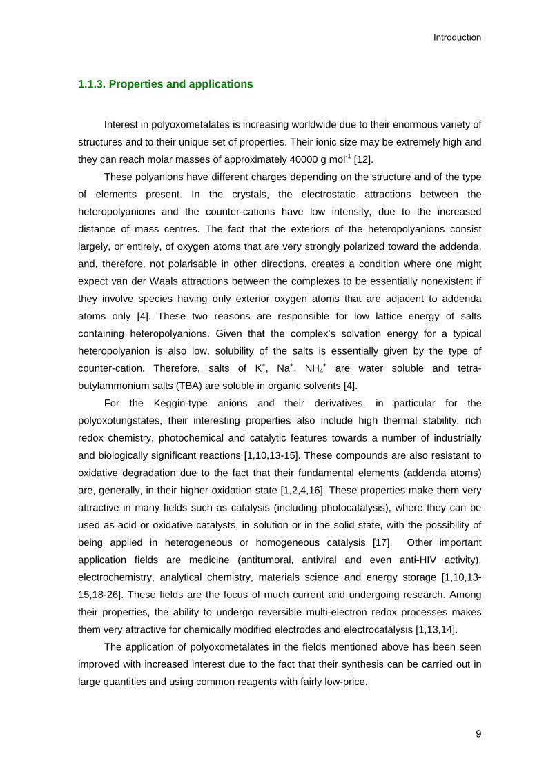
Polythiophenes (PTs) (Fig. 1.6) are one of the most important classes of
conjugated polymers, with a wide range of applications such as conducting films,
electrochromic, and field-effect transistors, which have been the subject of a number of
publications [100,101]. They result from the polymerization of thiophenes that become
conducting materials when electrons are added or removed from the conjugated π-orbitals
via doping, done by intentionally adding elemental impurities [102].
Figure 1.6. Examples of polythiophenes: (a) poly(thiophene-2,5-diyl), PTh and (b) poly(ethylenedioxythiophene), PEDOT.
Despite the large amount of work devoted to electrogenerated PTs, the mechanism
of the electropolymerization of thiophene has been little considered. This probably arises
from the fact that it is generally admitted that the electropolymerization of aromatic
compounds occurs via a unique mechanism which has been more extensively analyzed
using pyrrole as a model compound [103,104]. An important aspect of the
electropolymerization reaction is that it proceeds with a specific electrochemical
stoichiometry. The oxidation of the monomer requires 2 electrons/molecule while the
excess of charge corresponds to the reversible oxidation or doping of the polymer.
Figure 1.7 shows, as an example, the mechanism of electropolymerization of five-
member ring heterocycles [105]. The first electrochemical step (E) consists in the
oxidation of the monomer to its radical cation. Since the electron-transfer reaction is much
faster than diffusion of the monomer from the bulk solution, it follows that a high
concentration of radicals is continuously maintained near the electrode surface. The
second step involves the coupling of two radicals to produce a dihydro dimer dication
which leads to a dimer after loss of two protons and rearomatization. This rearomatization
constitutes the driving force of the chemical step (C). Due to the applied potential, the
dimer, which is more easily oxidized than the monomer, loses an electron to give its

Chapter 1
20
radical form and undergoes further coupling with a monomer radical.
Electropolymerization then proceeds through successive electrochemical and chemical
steps according to a general E(CE), scheme, until the oligomer becomes insoluble in the
electrolytic medium and precipitates onto the electrode surface. It is firmly established that
the oxidation of the monomer leads to the radical cation and that the electropolymerization
process is not diffusion-limited. The initial deposition step and the propagation process
during electropolymerization are less clearly understood and are still a matter of
controversy.
Figure 1.7. Mechanism of electropolymerization of heterocycles [adapted from 105].
Polythiophenes and their derivatives have been less used in the field of
electropolymerization with polyoxometalates than polyaniline and polypyrrole. However,
some examples can still be found in the literature. Most of papers published concerning
the modification of electrodes by electrodeposition of polythiophenes with incorporation of
polyoxometalates belong to Bidan and collaborators [106-111]. In their studies the Keggin-
type [PMo12O40]3-, [PW12O40]
3- and [SiW12O40]4- were used [106-109], as well as the
Dawson structure [P2W18O62]6- [110,111]. Out of many derivatives of polythiophenes,
poly(ethylenedioxythiophene), PEDOT, has recently been of interest as a particularly
stable, highly conductive and electroactive polymer. Recent reports are consistent with the
view that PEDOT shows promise for the design of novel composite materials with
improved stability [112,113] for electrode modification. Examples with this polymer will be
discussed in Chapter 6.

Introduction
21
1.3.2. Layer-by-layer Method
In recent years, the construction of self-assembled ultrathin films has attracted
considerable attention due to their potential applications in molecular and nano-devices.
Layer-by-layer (LbL) self-assembly has proved to be a promising method for the
fabrication of ultrathin films. It is based on the alternate adsorption on the substrate
surface of oppositely charged species from dilute solutions, and film formation is attributed
primarily to electrostatic interactions and van der Waals forces [114-117]. Consecutive
cycles with alternating adsorption of oppositely charged species result in stepwise growth
of films as illustrated in Fig. 1.8.
Figure 1.8. Scheme of the electrostatic layer-by-layer self-assembly of oppositely charged polyelectrolytes [116].
Combinations of cationic and anionic polyelectrolytes, or of these with smaller ionic
species, have been reported. Given the large number of materials which can be easily
incorporated into multilayer films, layer-by-layer deposition is a rather general approach
for the fabrication of complex surface coatings [116].
Since the layer-by-layer method is based on the attractive interaction of
complementary charges, the compound used needs to have a minimal number of charged
groups, below which the method does not work. The presence of large hydrophobic
fragments in the polyelectrolytes reduces the charge density, and may sterically hamper
the necessary ion-ion interactions which may be disadvantageous [18,116]. This

Chapter 1
22
interpretation was linked to the idea of a critical minimum value of charge density for LbL,
which is necessary to enable successful film growth. Experiments with weak
polyelectrolytes, in the form of statistical copolymers of charged and non-charged repeat
units, supported this idea [118-120].
However, this concept of a minimum value of charge density is oversimplified, since
some polymers with an unexpectedly low charge density have been successfully grown in
multilayer films by layer-by-layer [121,122]. Fisher et al. suggested that successful
deposition requires appropriate matching of the charge density of the polyelectrolyte pair
used, rather than a minimum charge density [123], although this does not necessary
exclude film formation [123].
There is a large number of polyelectrolytes that are used for film formation using the
layer-by-layer process. The most used, commercially available, ones are presented in Fig.
1.9. From these, the best studied system is by far the poly(allylamine)(c)/poly(styrene
sulfonate)(e) pair.
Figure 1.9. Examples of standard polyelectrolytes used in layer-by-layer method: (a) poly(acrylic
acid), (b) poly(vinylsulfate), (c) poly(allylamine), (d) poly(diallyldimethylammonium chloride), (e)
poly(styrene sulfonate) and (f) poly(ethyleneimine).
An important feature of the layer-by-layer method is that different substrates can be
used. Usually, the choice of substrate depends on the analytical methods that will be
used. Glass, quartz, silicon wafers, gold coated supports and glassy carbon are materials
used most frequently. Due to their transparency, ITO, glass and quartz are often applied
(d) (c)
(e) (f)
(b) (a)

Introduction
23
for characterization by UV-Visible and Infrared spectroscopy. Gold-coated surfaces and
glassy carbon enable electrochemical studies to be carried out [116].
This method is of great versatility due to the broad processing window and to the
many control parameters that can be changed such as concentration, adsorption time,
ionic strength, temperature, pH, among others. It also provides thickness control at the
nanometer level, can be easily adapted for automated fabrication and permits co-
assembly with different functional components [18,124].
Owing to its numerous advantages, the layer-by-layer approach has been
successfully utilized to fabricate POM-containing multilayer films consisting of synthesized
or natural polyelectrolytes. For example, thin films based on large polyoxometalates, such
as [Co4(H2O)2P4W30O112]16−, [Eu(H2O)P5W30O110]
12− and [Na(H2O)P5W30O110]14− [124], have
been successfully fabricated on ITO electrodes, using poly(ethylenimine) (positively
charged) and poly(styrenesulfonate) (negatively charged), as the anchorage layers, and
poly(allylamine hydrochloride) as the source of polycations.
Keggin–type polyoxometalates were also used for the preparation of ultrathin
multilayer films with polyelectrolytes on the surface of different types of electrodes. Early
studies have been reviewed [13]. Several studies use the parent Keggin silicotungstate
[SiW12O40]4- as the anion and, for example, polyaniline [125], chitosan [126], or
poly(diallyldimethylammonium chloride) [127] as the counter cation source. Other Keggin-
type and related polyoxometalates such as [Eu(SiW11O39)2]13-, [SiMo11VO40]
5- and
[ZnW11M(H2O)O39]n- (M = Cr, Mn, Fe, Co, Ni, Cu or Zn) were successfully immobilized on
a 4-aminobenzoic acid modified glassy carbon electrode, through layer-by-layer assembly
with a quaternized poly(4-vinylpyridine) partially complexed with [Os(bpy)2Cl]1+/2+ (QPVP-
Os) as counterion [128-131]. Poly(ethylenimine) has also been used as the polycation
source [132,133] this will be discussed in Chapter 5.
The use of polymeric cations is not necessary for growing films with Keggin anions.
For example, complex films based on the heteropolyacids H3PW12O40, H3PMo12O40 or
H4SiMo12O40, have been built onto glassy carbon electrodes with methyl viologen and with
the cationic meso-tetra(4N-methylpyridyl porphyrin) [134]. This cation was also used to
immobilize the Keggin-type polyoxometalates [SiW12O40]4-, [EuPW11O39]
4- [135] and
[SiW11FeIII(H2O)O39]5- [136]. There are only a few examples of use of transition metal
mono-substituted Keggin polyoxotungstate anions in films prepared by the layer-by-layer
self-assembly method [131,136].
Chapter 1
24
1.3.3. Carbon Paste Electrodes
Carbon paste electrodes (CPEs) are composite electrodes because they result from
the combination of two or more materials. They consist of a mixture of, at least, an
electrically conducting carbon powder and an organic liquid (binder). A portion of this
paste is then packed into the cavity of the carbon paste electrode body and the surface
smoothed on a weighing paper. They have been widely applied in electrochemistry owing
to their many advantages: inexpensive, easy to prepare, easy to handle, have low
background currents and their surface renewal is rapid [137].
Among the advantageous properties and characteristics listed above, CPEs allow
the preparation of electrodes with a desired composition and, hence, with pre-determined
properties. The choice of carbon paste components (carbon powder and pasting liquid),
their ratio in the mixture and the way in which the CPEs are prepared (homogenization of
the paste, packing of the paste in the electrode body, etc.) are important aspects that
determine the properties, characteristics and behaviour of CPEs [138]. Generally, the
organic liquid used as the binder component of pastes is a non-conductive mineral oil,
such as nujol or liquid paraffin. Owing to their chemical inertness, as well as good
adhesive ability, these viscous liquids have been widely used in the process of fabricating
traditional CPEs. However, since these binders are not conductive which, to some extent,
weakens the electrochemical response, other pasting binders have been used to improve
the carbon paste electrode response. Much has been published about CPEs using ionic
liquids mixed with organic binders, or as their substitutes [139-141]. Other carbon
composite electrodes based on graphite and cellulose acetate [142], or graphite and
poly(vinyl chloride) [143,144], have also been developed. Graphite-epoxy composite
electrodes have been used as substrates for electrochemical biosensors [145].
Four preparative methods can be used to modify the surface or composition of the
CPE, namely adsorption, covalent binding, dissolution and direct mixing, among which
direct mixing is the most common [137]. In general, the modifiers used with direct mixing
should be insoluble in the analyte solution or they should, at least, strongly adsorb to the
paste components in order to avoid dissolution of the modifier from the electrode surface
during measurements. Therefore, for studies in aqueous solutions, the traditional salts of
POMs and alkali metals, like Na+ or K+, cannot be directly used as bulk modifiers of CPEs
owing to their good solubility in water. However, inorganic–organic hybrids of POMs such
as tetra-butylammonium (TBA) salts of the lacunary and transition-metal monosubstituted
Keggin-type anions are insoluble in aqueous solutions [11].

Introduction
25
Several research groups have devoted their studies to the preparation of carbon
paste electrodes using polyoxometalates. Most work published in the literature concerns
the parent Keggin anions [88,146-152]. Wang’s group developed several different CPEs
using the Keggin type [PMo12O40]3- and [SiMo12O40]
4- [88,150-152]. Some were prepared
just by direct mixing of POM with the graphite powder. However, they also developed
PMo12-doped conducting PPy composite material bulk-modified CPEs [88], and CPEs with
hybrid nanoparticles [152]. Other authors describe the fabrication of non-conventional
CPEs. Li et al. developed CPEs containing Keggin type [PMo12O40]3- anions encapsulated
in modified mesoporous MCM-41 molecular sieves [148]. Liang et al. reported a PMo12
bacterial cellulose nanofiber-based CPE [153]. In the literature several papers concerning
CPEs with POMs can also be found where organic binders have been substituted by other
pasting binders such as ionic liquids, to improve the carbon paste electrode response
[141,154].
The preparation of CPEs using mono-substituted polyoxometalates is less common
and only a few are available in the literature. Hamidi et al. reported the preparation of
CPEs with PW11Fe supported on amorphous silica, organofunctionalized with 3-
aminopropyl(triethoxy)silane (APS) [155]. Other authors have used the mono-substituted
PMo11M' with M' = Co and Zn [38] and SiW11Co [156].
1.4. Electrochemical techniques
1.4.1. Cyclic voltammetry
Cyclic voltammetry is an effective, versatile technique which allows the
characterization of electroactive compounds, i.e., that can be oxidized and/or reduced,
and studying the reversibility of the oxidation and/or reduction [157]. It also allows
evaluating the presence of chemical steps associated with electron transfer, verifying the
occurrence of adsorption of reagents or of products on the electrode surface.
This technique consists in applying a potential sweep to the working electrode,
within limits Emin and Emax. The initial potential, Ei, and final potential, Ef, may or may not
be the same as Emin or Emax, and the initial sweep can be in the positive direction (to cause
an oxidation) or negative direction (to cause a reduction).

Chapter 1
26
The response, current versus potential is called a cyclic voltammogram. Figure 1.10
shows a typical cyclic voltammogram of a reversible process and the characteristic
parameters that can be easily obtained graphically.
0.0 0.1 0.2 0.3 0.4 0.5
-12.0
-8.0
-4.0
0.0
4.0
8.0
12.0
Ipa/2
Epa/2
Ipc
Ipa
Epc
Epa
I / µ
A
E / V vs. Ag/AgCl Figure 1.10. Cyclic voltammogram for a reversible system: 1 mM K3[Fe(CN)6] + 1 M KCl, scan rate
20 mV s-1.
In the cyclic voltammetry of reversible reactions, i. e. those with fast electrode
kinetics relative to the time-scale of the sweep, the product of the initial oxidation or
reduction is then reduced or oxidised, respectively, on reversing the scan direction.
Theoretical analysis of the wave shape leads to following equation for the peak current,
exemplified for an oxidation (Randles-Sevcik equation) [158,159]:
Ipa = 2.69 x 10⁵ n 3/2 A DR 1/2 [R]∞ ν1/2
where n is the number of electrons involved in the process, A is the electrode surface
area (cm2), DR the diffusion coefficient (cm2 s-1), [R]∞ the bulk concentration of species
(mol cm-3), ν is the scan rate (V s-1) and Ipa the anodic peak current (A).
It must be emphasised that a reversible cyclic voltammogram can only be observed
if both O and R (O + ne- → R) are stable and the kinetics of the electron transfer process
are fast, so that at all potentials and potential scan rates the electron transfer process on

Introduction
27
the surface is in equilibrium so that surface concentrations follow the Nernst equation
[160].
The information obtained from previous equation is, generally, presented in the form
of a diagnostic test for cyclic voltammograms of reversible processes [158-160]:
• Ip α ν1/2
• Ep independent of ν
• Ep – Ep/2= 56.6 / n (mV)
• ∆ Ep= Epa – Epc= 57.0 / n (mV)
• Ipa / Ipc= 1
For a completely irreversible reaction only the oxidation and reduction
corresponding to the initial sweep direction appears, since re-reduction or re-oxidation,
respectively, cannot occur, i.e. there is no reverse peak [159]. However the majority of
redox couples fall between the two extremes and exhibit quasi-reversible behaviour. This
means that the reverse peak appears but is smaller than the forward peak [158]. For
electrochemically quasi-reversible reactions, the surface concentrations are controlled
both by kinetics and diffusion. The peaks separation (∆Ep) increases when scan rate
increases and smaller currents are observed, but peak current continues to be
proportional to v1/2.
If the reagent or the product of an electrode reaction is adsorbed strongly or weakly
at the electrode, there is a change in the shape of the cyclic voltammogram [158,159].
The features exhibited by a cyclic voltammogram of adsorbed species on a surface differ
from the typical voltammogram obtained for species in solution. This occurs since the
mass transfer component of the current can be disregarded due to adsorption of the
electroactive species at the electrode surface. If the electron transfer is reversible,
symmetric cyclic voltammograms can be obtained due to the fixed amount of reactant
adsorbed on the surface [157]. In the case of adsorbed species, ∆Ep tends to zero for
reversible reactions and Ip is directly proportional to ν [157].
1.4.2. Electrochemical impedance spectroscopy
Electrochemical impedance spectroscopy (EIS) can be considered nowadays as a
key technique for characterisation of electrochemical systems. It provides a global vision

Chapter 1
28
of the electrical features of the electrode/solution interface. Analysis of the system
response contains information about the interface, its structure and reactions taking place
and this information is of great use in electrochemistry.
From the theoretical point of view, impedance is the most complete parameter that
can be measured in an electrochemical system since if it is measured throughout an
infinite range of frequencies, it contains all the information that can be obtained about the
system through purely electric means [161]. The power of EIS resides in the fact that,
being considered a stationary state technique, it allows the study of processes with time
constants that vary throughout several orders of magnitude. Its stationary character
permits that each measurement is the result of an average of values, obtaining this way
high levels of precision, while the large range of frequencies of the instrument makes
possible the study of a wide range of interfacial processes [161].
The principle of this technique consists in applying a small perturbation to the
system. A sinusoidal variation of potential of small amplitude is superimposed on an
applied fixed potential, while in the methods based on linear potential sweep, the system
is disturbed far from equilibrium. The fact that the perturbation is small is advantageous in
terms of the mathematical equation resolution because it is possible to use limiting forms
of these equations, that are normally linear, besides the fact that it allows the investigation
of electrochemical phenomena close to equilibrium and over a wide range of frequencies.
Generally the response to the applied perturbation is sinusoidal and may differ in phase
and amplitude from the applied signal. The measurement of phase difference and
amplitude (i.e. impedance) allows the analysis of electrode processes in relation to the
contributions of diffusion, kinetics, double layer, amongst others [159].
Electrochemical impedance spectroscopy results can be analysed by two distinct
approaches. The first consists in developing mathematical methods based on the kinetics
of heterogeneous reactions involved and the second uses the concept of equivalent
electrical circuit [162], based on the fact that, in principle, every electrochemical cell can
be represented by an electrical model.
For a simple electrode process, commonly used combinations for faradaic reactions
include a component representing the transport by diffusion, a component representing
the kinetics (purely resistive) and another component representing the interfacial
region/double layer (capacitive). Considering the application of a sinusoidal signal:
E(t) = E0 sin (ωt)

Introduction
29
where ω represents the perturbation frequency (rad s-1), the response is:
)(sin)( 0 ϕ+= ωtZ
EtI
where φ is the phase angle between the perturbation and the response. The
proportionality factor, Z, between the perturbation and the response is the electrical
impedance. The impedance is characterized by the amplitude and phase angle and can
be described as follows:
"i´ ZZZ += ( ) ϕcos/´ 00 IEZ = ( ) ϕsin/" 00 IEZ = So:
( ) ( ) 00
1/222 /||"´ IEZZZ ==+
This way, any electrochemical cell can be represented in terms of an equivalent
electrical circuit, [159] e.g. a Randles circuit (Fig. 1.11), which includes the following
parameters: a cell resistance RΩ (resistance of solution, electrode materials, electrical
leads etc.), a double layer capacitance Cd and the impedance of the faradaic process Zf.
The impedance Zf can be subdivided in two equivalent ways:
1. A resistance, Rs, in series with a pseudo capacitance, Cs.
2. A charge transfer resistance, Rct, and an impedance measuring the difficulty of
mass transfer of electroactive species, called the Warburg impedance, Zw.
Ic
If + IcZf
If
RΩ
Cd Ic
If + IcZf
If
RΩ
Cd
Figure 1.11. Equivalent electrical circuit of an electrochemical cell for a simple electrode process [159].
The most often used representation of the impedance spectrum is complex plane
(Nyquist) plots, in which the imaginary part of impedance (Z'') is plotted vs. the real part

Chapter 1
30
(Z'), for each frequency. Another representation is the Bode plots (log |Z| and φ vs. Log
(ω)) [163].
Figure 1.12 shows a complete Randles type equivalent circuit of a simple charge
transfer reaction.
Figure 1.12. Complete Randles type equivalent electric circuit. The circuit comprises a cell
resistance, RΩ, in series with a parallel combination of a double layer capacity, Cd, and a charge
transfer resistance, Rct, together with a Warburg impedance, ZW.
Separating the components in and out of phase, it can be shown that:
( ) ( )21/2ct
2d
22
d1/2
1/2ct
Ω1
´−
−
+++
++=
ωRCωCω
ωRRZ
σσ
σ
( )( ) ( )21/2
ct2d
22
d1/2
1/2d
221/2ctd
1"
−
−−
+++
+++=−
σωωσω
σωσσωω
RCC
CRCZ
These components are represented in a plot in the complex plane (Fig. 1.13) called
the Sluyters or Cole-Cole plot. Two limiting forms of these equations [159] are:
1. When ω → 0:
1/2ctΩ´ −++= σωRRZ
d21/2 2" CσσωZ −−= −
This low frequency limit is a straight line with a slope of 1 that extrapolated to the
real axis, gives an intercept of (RΩ + Rct - 2σ2Cd). The line corresponds to a reaction
controlled only by diffusion, and the impedance is the open circuit, infinite diffusion
Warburg impedance, the phase angle being π/4.
Rct
Zw
Cd
RΩ

Introduction
31
2. When ω → ∞ (kinetic control):
In the high frequency limit the control is purely kinetic and Rct >> Zw. The electric
analogy is a parallel combination RC. Eliminating the diffusion terms:
2ct
2d
2ct
Ω1
´RC
RRZ
ω++=
2ct
2d
2
2ctd
1"
RC
RCZ
ωω
+−=
The real component of impedance tends to at high frequencies RΩ, and to RΩ + Rct at
low frequencies. Eliminating the frequency parameter from the previous expressions the
relationship between the imaginary and real components of impedance, can be obtained:
( )2
ct22
ctΩ 2
"2
´
=+
−−R
ZR
RZ
This expression is the equation of a circle of radius Rct/2 with intercepts on the Z´
axis of RΩ (ω → ∞) and of RΩ + Rct (ω → 0).
Figure 1.13. Complex plane impedance plot for a simple electrochemical system: O + ne- → R.
RΩ+ Rct RΩ
RΩ + Rct/2 RΩ + Rct - 2σ2Cd
ω
Kinetic control Diffusion control
High frequencies Low frequencies
- Zʼʼ
Zʼ

Chapter 1
32
Real systems, using solid electrodes, rarely conform to this ideal behaviour. The
roughness and the porosity, usually encountered when using solid electrodes, give rise to
changes in behaviour that can be modelled using the so-called constant phase element
(CPE). In such systems, for electron transfer reactions the CPE often manifests itself as a
non-ideal capacitor; in the case of a blocked interface this element is described by:
nCiQ )/(1CPE ω−=
It has been demonstrated that at the limit of porous electrodes, the CPE exponent is
n = 0.5 while for perfect uniform electrode surface it is n = 1 [159].
1.5. Scope of the work
The work presented in this thesis had as main goal the development of new
modified electrodes incorporating polyoxotungstates through different methodologies.
Chapter 2 concerns the synthesis of different types of Keggin type
polyoxotungstates which include the potassium (water soluble) and tetra-butylammonium
salts of the lacunary anions, [XW11O39] (n+4)- (where X = PV and SiIV), and of the metal
substituted [XW11M'(L)O39]m- (where M = Fe, Co and Mn). All prepared compounds were
characterized by thermal and elemental analysis, thermogravimetry, and infrared
absortion spectroscopy.
Chapter 3 describes the functionalisation of glassy carbon electrodes by deposition
of tetra-butylammonium salts of the lacunary (X = Si) and of the mono-substituted anions
(M = Fe and Co), using the droplet evaporation method. The electrochemical behaviour of
the immobilized POMs was evaluated by cyclic voltammetry. The morphological features
of the modified electrodes were also assessed by scanning electron microscopy. The
study of the behaviour, in aqueous solution, of the prepared potassium salts of
silicotungstates was performed for comparison and is also presented in this chapter.
Chapter 4 presents the preparation of carbon composite electrodes with tetra-
butylammonium salts of the lacunary (X = P) and of the mono-substituted anion (M = Co),
with and without poly(hexylmethacrylate). These modified electrodes were characterized

Introduction
33
using [Fe(CN)6]3-/4- model electroactive species, in aqueous solution, by cyclic
voltammetry.
Chapter 5 describes the preparation of modified GCE, by the layer-by-layer
methodology, using the potassium salts of the lacunary (X = Si) and of the mono-
substituted anions (M = Fe, Co for X= Si and M = Fe for X = P), and poly(ethylenimine).
The modified electrodes were characterized using cyclic voltammetry, electrochemical
impedance spectroscopy and scanning electron microscopy. The growth of the multilayer
films adsorbed on a quartz slide was monitored by UV–Vis absorption spectroscopy.
Chapter 6 presents the preparation of parent, lacunary and mono-substituted
(M = Fe, Co) silicotungstates doped PEDOT modified electrodes. These modified
electrodes were prepared by controlled electrodeposition of composite (hybrid) films of
PEDOT, with the Keggin-type SiW12, SiW11, SiW11Fe and SiW11Co. The electrochemical
behaviour of the immobilized POMs was examined.
Chapter 7 of this thesis is dedicated to the final conclusions.

Chapter 1
34
1.6. References
[1] M. T. Pope, Heteropoly and Isopoly Oxometalates, Springer Verlag, 1983.
[2] M. T. Pope, Comprehensive Coordination Chemistry, G. Wilkinson (ed.), Pergamon Press,
1987, chapter 3.
[3] Y. P. Jeannin, Chem. Rev. 98 (1998) 51.
[4] L. C. W. Baker, D. C. Glick, Chem. Rev. 98 (1998) 3.
[5] J. F. Keggin, Nature 131 (1933) 908.
[6] S. Himeno, M. Takamoto, T. Ueda, J. Electroanal. Chem. 465 (1999) 129.
[7] A. Tézé, J. Canny, L. Gurban, R. Thouvenot, G. Hervé, Inorg. Chem. 35 (1996) 1001.
[8] J. J. Cowan, A. J. Bailey, R. A. Heintz, B. T. Do, K. I. Hardcastle, C. L. Hill, I. A. Weinstock,
Inorg. Chem. 40 (2001) 6666.
[9] A. Tézé, G. Hervé, J. Inorg. Nucl. Chem. 39 (1977) 2151.
[10] C. L. Hill, C. M. Prosser-McCartha, Coord. Chem. Rev. 143 (1995) 407.
[11] A. M. V. Cavaleiro, J. D. Pedrosa de Jesus, H. I. S. Nogueira, Metals Clusters in Chemistry, P.
Braunstein, L. A. Oro, P. R. Raithly (eds), Wiley-VCH, 1999, chapter1.
[12] A. Müller, F. Peters, M. T. Pope, D. Gatteschi, Chem. Rev. 98 (1998) 239.
[13] M. Sadakane, M.E. Steckhan, Chem. Rev. 98 (1998) 219.
[14] B. Keita, L. Nadjo, J. Mol. Catal. A: Chem. 262 (2007) 190.
[15] R. Neumann in: J. E. Bäckvall (Ed.), Modern Oxidative Methods, Wiley-VCH, Weinheim, 2004,
ch. 8.
[16] C. L. Hill, Chem. Rev. 98 (1998) 1.
[17] I. V. Kozhevnikov, Chem. Rev. 98 (1998) 171.
[18] D.G. Kurth, D. Volkmer, R.V.Klitzing in: G. Decher, J. B. Schlenoff (Eds.), Multilayer Thin
Films: Sequential Assembly of Nanocomposite Materials, Wiley – VCH, Weinheim, 2003.
[19] M. T. Pope, A. Müller (eds.), Polyoxometalate Chemistry. From Topology via Self-assembly to
Applications, Kluwer, Dordrecht, 2001.
[20] E. Coronado, C. Giménez-Saiz, C. J. Gómez-Garcia, Coord. Chem. Rev. 249 (2005) 1776.
[21] E. Coronado, C. J. Gómez-Garcia, Chem. Rev. 98 (1998) 273.
[22] J.M. Clemente-Juan, E. Coronado, Coord. Chem. Rev. 193–195 (1999) 361.
[23] P. Gomez-Romero, Adv. Mater. 13 (2001) 163.
[24] D.E. Katsoulis, Chem. Rev. 98 (1998) 359.
[25] J.T. Rhule, C.L. Hill, D.A. Judd, Chem. Rev. 98 (1998) 327.
[26] R. Neumann, Prog. Inorg. Chem. 47 (1998) 317.
[27] J. M. Fruchart, G. Hervé, J. P. Launay, R. Massart, J. Inorg. Nucl. Chem. 88 (1976) 1627.
[28] M. T. Pope, G. M. Varga, Inorg. Chem. 5 (1966) 1249.
[29] B. Keita, L. Nadjo, R. Parsons, J. Electroanal. Chem. 258 (1989) 207.
[30] G. Hervé, Ann. Chim. 6 (1971) 219.

Introduction
35
[31] G. Hervé, Ann Chim. 6 (1971) 287.
[32] F. A. R. Couto, A. M. V. Cavaleiro, J. D. Pedrosa de Jesus, J. Simão, Inorg. Chim. Acta 281
(1998) 225.
[33] Y. Cui, L. Xu, W. J. Wang, G. G. Gao, E. B. Wang, Chin. J. Chem. 24 (2006) 316.
[34] M. Takamoto, T. Ueda, S. Himeno, J. Electroanal. Chem. 521 (2002) 132.
[35] K. Maeda, S. Himmeno, T. Osakai, T. Hori, J. Electroanal. Chem. 364 (1994) 149.
[36] N. M. Alpatova, V. E. Kazarinov, M. D. Levi, E. V. Ovsyannikova, Russ. J. Electrochem. 30
(1994) 775.
[37] M. S. Balula, J. A. Gamelas, H. M. Carapuça, A. M. V. Cavaleiro, W. Schlindwein, Eur. J.
Inorg. Chem. (2004) 619.
[38] X. Liu, G. Gao, L. Xu, F. Li, L. Liu, N. Jiang, Y. Yang, Solid State Sci. 11 (2009) 1433.
[39] J. E. Toth, F. C. Anson, J. Electroanal. Chem. 256 (1988) 361.
[40] M. Sadakane, E. Steckhan, Acta Chem. Scan. 53 (1999) 837.
[41] M. T. Pope, A. Müller, Angew. Chem. Int. Ed. Engl 30 (1991) 34.
[42] F. Zonnevijlle, C. M. Tourné, G. F. Tourné, Inorg. Chem. 21 (1982) 2742.
[43] P. Souchay, Ann. Chim. 18 (1943) 169.
[44] F. Osmond, Bull Soc. Chim. 47 (1887) 745.
[45] M. T. Pope, A. Müller, Polyoxometalates: From Platonic Solids to Anti-Retroviral Activity (1994)
191.
[46] T. Okuhara, N. Misuno, M. Misono, Adv. Catal. 41 (1996) 113.
[47] K. Maeda, H. Katano, T. Osakai, S. Himeno, A. Saito, J. Electroanal. Chem. 389 (1995) 167.
[48] B. Keita, L. Nadjo, J. Electroanal. Chem. 227 (1987) 77.
[49] S. Himeno, M. Takamoto, T. Ueda, J. Electroanal. Chem. 465 (1999) 129.
[50] W. Sun, H. Liu, J. Kong, G. Xie, J. Deng, J. Electroanal. Chem. 437 (1997) 67.
[51] A. Müller, L. Dloczik, E. Diemann, M. T. Pope, Inorg. Chim. Acta, 257 (1997) 231.
[52] J. E. Toth, F. C. Anson, J. Am. Chem. Soc. 111 (1989) 2444.
[53] J. E. Toth, J. D. Melton, D. Cabelli, B. H. J. Bielski, F. C. Anson, Inorg. Chem. 29 (1990) 1952.
[54] S. Dong, M. Liu, J. Electroanal. Chem. 372 (1994) 95.
[55] F. Zonnevijlle, C. M. Tourné, G. F. Tourné, Inorg. Chem. 21 (1982) 2751.
[56] L. Cheng, H. Sun, B. Liu, J. Liu, S. Dong, J. Chem. Soc. Dalton Trans. (1999) 2619.
[57] X. Zang, M. T. Pope, M. R. Chance, G. B. Jameson, Polyhedron 14 (1995) 1381.
[58] M. Sadakane, E. Steckhan, J. Mol. Cat. A 114 (1996) 221.
[59] C.Rong, F. C. Anson, Inorg. Chem. 33 (1994) 1064.
[60] A. Schouten, B. Cros, Can. J. Chem. 60 (1982) 1368.
[61] R. W. Murray, A. G. Ewing, R. A. Durst, Anal. Chem. 59 (1987) 379.
[62] P. R. Moses, P. Wier, R. W. Murray, Anal. Chem. 47 (1975) 1882.
[63] R. A. Durst, A. J. Bäumner, R. W. Murray, R. P. Buck, C. P. Andrieux, Pure & Appl. Chem. 69
(1997) 1317.
[64] B. Keita, L. Nadjo, J. Electroanal. Chem. 243 (1988) 87.

Chapter 1
36
[65] K. Reybier, J.-P. Malugani, S. Fantini, M. Herlem, B. Fahys, J. Electrochem. Soc. 149 (2002)
E96.
[66] B. Keita, D. Bouaziz, L. Nadjo, J. Electroanal. Chem. 284 (1990) 431.
[67] B. Keita, K. Essaadi, L. Nadjo, J. Electroanal. Chem. 259 (1989) 127.
[68] B. Keita, L. Nadjo, J. Electroanal. Chem. 240 (1988) 325.
[69] D. Martel, A. Kuhn, Electrochim. Acta 45 (2000) 1829.
[70] A. Kuhn, N. Mano, C. Vidal, J. Electroanal. Chem. 462 (1999) 187.
[71] P.J. Kulesza, G. Roslonek, L.R. Faulkner, J. Electroanal. Chem. 280 (1990) 233.
[72] D. Ingersoll, P.J. Kulesza, P.J. Faulkner, J. Electrochem. Soc. 141 (1994) 140.
[73] X. Wang, Z. Kang, E. Wang, C. Hu, J. Electroanal. Chem. 523 (2002) 142.
[74] M.I. Prodromidis, P.G. Veltsistas, C.E. Efstathiou, M.I. Karayannis, Electroanalysis 13 (2001)
960.
[75] H.M. Carapuça, M.S. Balula, A.P. Fonseca, A.M.V. Cavaleiro, J. Solid State Electrochem.10
(2006) 10.
[76] G. Bidan, E. M. Genies, M. Lapkowski, J. Electroanal. Chem. 251 (1988) 297.
[77] http://98.131.55.98/is_a_ele_ecp.asp (25/07/2010).
[78] E.M. Geniès, G. Bidan, A.F. Diaz, J. Electroanal. Chem. 149 (1983) 101.
[79] P. Wang, Y. Li, J. Electroanal. Chem. 408 (1996) 77.
[80] S. Dong, W. Jin, J. Electroanal. Chem. 354 (1993) 87.
[81] S. Dong, M. Liu, Electrochim. Acta 39 (1994) 947.
[82] H. Sung, H. So, W. Paik, Electrochim. Acta 39 (1994) 645.
[83] P. Gómez-Romero, M. Lira-Cantu, Adv. Mater. 9 (1997) 144.
[84] T. F. Otero, S. A. Cheng, D. Alonso, F. Huerta, J. Phys. Chem. B 104 (2000) 10528.
[85] T. F. Otero, S. A. Cheng, F. Huerta, J. Phys. Chem. B 104 (2000) 10522.
[86] H. X. Guo, Y. Q. Li, L. F. Fan, X. Q. Wu, M. D. Guo, Electrochim. Acta 51 (2006) 6230.
[87] M. D. Guo, H. X. Guo, J. Electroanal. Chem. 585 (2005) 28.
[88] X. L. Wang, H. Zhang, E. B. Wang, Z. B. Han, C. W. Hu, Mater. Lett. 58 (2004) 1661.
[89] L. M. Abrantes, C. M. Cordas, E. Vieil, Electrochim. Acta 47 (2002) 1481.
[90] P. Gomez-Romero, O. Ayyad, J. Suàrez-Guevara, D. Muñoz-Rojas, J. Solid State
Electrochem. 14 (2010) 1939.
[91] E. Nguema, V. Vigneras, J. L. Miane, P. Mounaix, Eur. Polymer J. 44 (2008) 124.
[92] P. Gomez-Romero, N. Casan-Pastor, M. Lira-Cantu, Solid State Ionics 101 (1997) 875.
[93] G. Siné, C. C. Hui, A. Kuhn, P. J. Kulesza, K. Miecznikowski, M. Chojak, A. Paderewska, A.
Lewera, J. Electrochem. Soc. 150 (2003) C351.
[94] P. C. Lekha, S. Subramanian, D. P. Padiyan, Journal of Materials Science 44 (2009) 6040.
[95] D. G. Shuchukin, D. V. Suiridov, Electrochem. Commun. 4 (2002) 402.
[96] M. Barth, M. Lapkowski, S. Lefrant, Electrochim. Acta 44 (1999) 2117.
[97] P. C. Lekha, E. Subramanian, D. P. Padiyan, Sensors Actuator B Chem. 122 (2007) 274.

Introduction
37
[98] A. Mahmoud, B. Keita, L. Nadjo, O. Oung, R. Contant, S. Brown, Y. Kouchkovsky, J.
Electroanal. Chem. 463 (1999) 129.
[99] B. Fabre, G. Bidan, Electrochim. Acta 42 (1997) 2587.
[100] I. Perepichka, D. Perepichka, H. Meng, F. Wudl, Adv. Mater. 17 (2005) 2281.
[101] L. Groenendaal, J. Dhaen, J. Manca, J. Van Luppen, E. Verdonck,; F. Louwet, L. Leenders,
Synth. Met. 115 (2003) 135.
[102] T. Yamamoto, Asia Mater. 2 (2010) 54.
[103] A. F. Diaz, J. Bagon, Handbook of Conducting Polymers; Stotheim, T. A. Ed, 1 (1986).
[104] E. Genies, G. Bidan, A. F. Diaz, J. Electroanal. Chem. 149 (1983) 113.
[105] Y. Wei, C. Chan, J. Tian, G. Jang, K. F. Hsueh, Chem. Mater. 3 (1991) 888.
[106] G. Bidan, E. M. Genies, M. Lapkowski, Synth. Met. 31 (1989) 327.
[107] G. Bidan, M. Lapkowski, J. P. Travers, Synth. Met. 28 (1989) C113.
[108] M. Lapkowski, G. Bidan, M. Fournier, Synth. Met. 41 (1991) 407.
[109] B. Fabre, G. Bidan, Adv. Mater. 5 (1993) 646.
[110] M. Lapkowski, G. Bidan, M. Fournier, Synth. Met. 41 (1991) 411.
[111] M. Lapkowski, G. Bidan, M. Fournier, Pol. J. Chem. 65 (1991) 1547.
[112] A. M. White, R. C. T. Slade, Electrochim. Acta 49 (2004) 861.
[113] L. Adamczyk, P. J. Kulesza, K. Miecznikowski, B. Palys, M. Chojak, D. Krawczyk. J.
Electrochem. Soc. 152 (2005) E98.
[114] G. Decher, Science 277 (1997) 1232.
[115] S.T. Dubas, J.B. Schlenoff, Macromolecules 32 (1999) 8153.
[116] P. Bertrand, A. Jonas, A. Laschewsky, R. Legras, Macromol. Rapid Commun. 21 (2000) 319.
[117] F.N. Crespilho, V. Zucolotto, O.N. Oliveira Jr, F.C. Nart, Int. J. Electrochem. Sci. 1 (2006)
194.
[118] N. G. Hoogeveen, M. A. C. Stuart, G. J. Fleer, M. R. Böhmer, Langmuir 12 (1996) 3675.
[119] N. G. Hoogeveen, M. A. C. Stuart, G. J. Fleer, J. Colloid Interface Sci. 182 (1996) 133.
[120] L Kolarik, D. F. Furlong, H. Joy, C. Struijk, R. Rowe, Langmuir 15 (1999) 8265.
[121] D. Cochim, M. Paßmann, G. Wilbert, R Zentel, E. Wischerhoff, A. Laschewsky,
Macromolecules 30 (1997) 4775.
[122] M. Paßmann, G. Wilbert, D. Cochim, R Zentel, Macromol. Chem. Phys. 199 (1998) 179.
[123] P. Fisher, A. Laschewsky, E. Wischerhoff, X. Arys, A. Jonas, R. Legras, Macromol. Symp.
137 (1999) 1.
[124] S. Liu, D.G. Kurth, B. Bredenkotter, D. Volkmer, J. Am. Chem. Soc. 124 (2002) 12279.
[125] Y. Wang, C. Guo, Y. Chen, C. Hu, W. Yu, J. Colloid Interface Sci. 264 (2003) 176.
[126] Y. Feng, Z. Han, J. Peng, J. Lu, B. Xue, L. Li, H. Ma, E. Wang, Mater. Lett. 60 (2006) 1588.
[127] S. Li, E. Wang, C. Tian, B. Mao, Y. Song, C. Wang, L. Xu, Mater. Res. Bull. 43 (2008) 2880.
[128] L. Cheng, J. Liu, S. Dong, Anal. Chim. Acta 417 (2000) 133.
[129] S. Zhai, Y. Chen, S. Wang, J. Jiang, Talanta 63 (2004) 927.
[130] L. Cheng, S. Dong, J. Electroanal. Chem. 481 (2000) 168.

Chapter 1
38
[131] J. Liu, L. Cheng, S. Dong, Electroanalysis 14 (2002) 569.
[132] S. Gao, T. Li, X. Li, R. Cao, Mater. Lett. 60 (2006) 3622.
[133] C. Li, X. Wang, H. Ma, F. Wang, Y. Gu, Electroanalysis 20 (2008) 1110.
[134] D. Martel, M. Gross, J Solid State Electrochem. 11 (2007) 421.
[135] G. Bazzan, W. Smith, L.C. Francesconi, Drain C.M. Langmuir 24 (2008) 3244.
[136] K. Shiu, F.C. Anson, J. Electroanal. Chem. 309 (1991) 115.
[137] K. Kalcher, Electroanalysis 2 (1990) 419.
[138] J. Lindquist, J. Electroanal. Chem. 52 (1974) 37.
[139] Y. Zhang, J. B. Zheng, Electrochim. Acta 52 (2007) 7210.
[140] G. Shul, J. Sirieix-Plenet, L. Gaillon, M. Opallo, Electrochem. Commun. 8 (2006) 1111.
[141] H. Liu, P. He, Z. Li, C. Sun, L. Shi, Y. Liu, G. Zhu, J. Li, Electrochem. Commun. 7 (2005)
1357.
[142] M.M. Barsan, E.M. Pinto, M. Florescu, C.M.A. Brett, Anal. Chim. Acta 635 (2009) 71.
[143] F. Abertús, A. Llerena, J. Alpízar, V. Cerdá, M. Luque, A. Ríos, M. Valcárcel, Anal. Chim.
Acta 355 (1997) 23.
[144] M. Luque, A. Ríos, M. Valcárcel, Anal. Chim. Acta 395 (1999) 217.
[145] Ü.A. Kirgöz, D. Odaci, S. Timur, A. Merkoçi, S. Alegret, N. Besün, A.Telefoncu, Anal. Chim.
Acta 570 (2006) 165.
[146] Z. Han, Y. Zhao, J. Peng, A. Tian, Y. Feng, Q. Liu, J. Solid State Chem. 178 (2005) 1386.
[147] H. Hamidi, E. Shams, B. Yadollahi, F. K. Esfahani, Talanta 74 (2008) 909.
[148] L. Li, W. Li, C. Sun, L. Li, Electroanal. 14 (2002) 368.
[149] Z. Han, Y. Zhao, J. Peng, Y. Feng, J. Yin, Q. Liu, Electroanalysis 17 (2005) 1097.
[150] Z. Han, Y. Zhao, J. Peng, Q. Liu, E. Wang, Electrochim. Acta 51 (2005) 218.
[151] X. Wang, E. Wang, Y. Lan, C. Hu, Electroanalysis 14 (2002) 1116.
[152] X. Wang, Z. Kang, E. Wang, C. Hu, Mater. Lett. 56 (2002) 393.
[153] Y. Liang, P. He, Y. Ha, Y. Zhou, C. Pei, X. Li, Electrochem. Commun. 11 (2009) 1018.
[154] B. Haghighi, H. Hamidi, Electroanalysis 21 (2009) 1057.
[155] H. Hamidi, E. Shams, B. Yadollahi, F. K. Esfahani, Electrochim. Acta 54 (2009) 3495.
[156] X. L. Wang, H. Y. Lin, G. C. Liu, B. K. Chen, Y. F. Bi, Chem. Res. Chin. Univ. 24 (2008) 129.
[157] A. J. Bard, L. R. Faulkner, Electrochemical Methods, Wiley, 2001
[158] C. M. A. Brett, A. M. Oliveira Brett, Electroanalysis, Oxford Chemistry Primers, 1998.
[159] A. M. O. Brett, C. M. A. Brett, Electrochemistry: Principles, Methods and Aplications, Oxford
University Press, 1993.
[160] R. Greef, R. Peat, L. M. Peter, D. Pletcher, J. Robinson, Instrumental methods in
Electrochemistry, Ellis Horwood Limited, Chichester, 1985.
[161] C. M. A. Brett, ECS Transactions 13 (2008) 67.
[162] J. Ross Macdonald, W. B. Johnson in: E. Barsoukov, J. R. Macdonalds (Eds), Impedance
Spectroscopy, Theory, Experiment and Applications, 2nd Edition, John Wiley and Sons, New York,
2005.

Introduction
39
[163] A. Lasia in B. E. Conway, J. O´M. Bocknis, R. E. White (Eds), EIS-Modern Aspects of
Electrochemistry nº 32, Kluwer, 2002.

Chapter 1
40

CHAPTER 2
POLYOXOMETALATES:
SYNTHESIS AND CHARACTERIZATION
Chapter 2
42
POLYOXOMETALATES: SYNTHESIS AND CHARACTERIZATION 41
2.1. Introduction 43
2.2. Experimental 46
2.2.1. Reagents 46
2.2.2. Instrumentation and methods 46
2.2.3. Synthesis 46
2.2.3.1. Synthesis of TBA4H4[SiW11O39] 47
2.2.3.2. Synthesis of TBA4Hx[SiW11M(H2O)O39]·nH2O, M = CoII, Fe
III 47
2.3. Potassium salts of lacunary and mono-substituted anions 48
2.4. Tetra-butylammonium salts of lacunary and mono-substituted anions 52
2.5. Conclusions 56
2.6. References 57

Polyoxometalates: synthesis and characterization
43
2.1. Introduction
The first polyoxometalate dates from 1826 when Berzelius described the yellow
precipitate that is produced when ammonium molybdate is added to phosphoric acid and
which is now known to be the ammonium phosphomolybdate (NH4)3[PMo12O40]·nH2O.
However, it was not until the discovery of the silicotungstic acids and their salts by
Marignac in 1862 that the analytical compositions of such heteropoly acids were precisely
determined [1]. Thereafter, the field developed rapidly through the twentieth century and
the synthesis of new salts was greatly improved. However, given the dimensions and
structural complexity of these anions, their characterization presented difficulties until
recently. Nowadays, with the development of new instrumental techniques such as
nuclear magnetic resonance (NMR), X-ray powder diffraction, amongst others, it is
possible to obtain more precise information about these compounds.
Generally, POMs preparation is based on reactions in aqueous solutions or in
organic solvents (or a mixture of solvents). The α-Keggin polyoxotungstates are prepared
by controlled acidification of aqueous solutions that contain the simple oxoanion (WO42-)
and species with the primary heteroatom (for example, HPO42-, SiO4
2-, amongst others)
(equation 2.1) [1,2].
The lacunary species of the Keggin anions can be obtained by the addition of
alkaline solutions to aqueous solutions containing these parent anions (equation 2.2), or
by acidification of aqueous solutions of sodium tungstate and oxoanions that contain the

Chapter 2
44
required heteroatom, at defined pH values (equation 2.3), whenever the heteroatom is
non-metallic [1,2]. If the heteroatom is a metal, a salt of this metal is used instead of the
oxoanion. Frequently, the lacunary anion can be changed into the Keggin anion if the pH
values of the solution are acid enough. For example, the lacunary [PW11O39]7- is stable
between pH values of 2 and 6, its conversion into the Keggin anion [PW12O40]3- occurring
by acidification.
12 WO42- + HPO4
2- + 23 H+ → [PW12O40]3- + 12 H2O (2.1)
[PW12O40]3- + (5-x) OH- → [HxW11O39]
(7-x)- + HWO42- + (2-x) H2O (2.2)
11 WO42- (aq) + HPO4
2- (aq) + 17 H+ (aq) → [PW11O39]7- (aq) + 9 H2O (l) (2.3)
The first mono-substituted polyanions [XW11M(H2O)O39]m- ([XW11M]) were known in
the middle of the nineteen sixties, with the pioneering work of Baker [3]. He proposed that
the anions with X = SiIV, CoII,III, (H2)2+ and M = CoII,III, GaIII belonged to a new category of
heteropolyelectrolytes, with an analogous structure to the Keggin anion [3]. Initially, the
majority of the work reported on mono-substituted polyanions involved the potassium
salts. In the literature, three different general methods can be found for the preparation of
the mono-substituted anions [XW11M] [4-6]:
Method 1: After isolation of the potassium salt of [XW11O39](n+4)-, this is reacted, in
hot aqueous solution or in suspension, with a solution containing the desired metal
cation, in a ratio slightly higher than the stoichiometric value for the cation.
Method 2: To an aqueous solution containing the [XW12O40]n- anion and the
desired metal cation, boiling KHCO3 or KCH3COO, is slowly added, until a pH
value compatible with the total conversion of XW12 to XW11 and compatible with
the stability of the formed complex. For X = P, pH = 5.0 – 5.5; X = Si, Ge, pH = 6.0
– 6.7.
Method 3 (direct method): Acidification of an aqueous solution containing a salt of
the element X (disodium hydrogenophosphate when the heteroatom is phosphor,

Polyoxometalates: synthesis and characterization
45
and sodium metassilicate when it is silicon [4,7,8]) and tungstate, in a molar
proportion of 1:11, respectively. The values of pH are 4.7 – 5.0 for X = P, and 6.0 –
6.7 for X = Si. Finally, an aqueous solution of the desired metal substituent is
added.
The stability of [XW11M(H2O)O39]m- species, in aqueous solution, depends on the pH
value. Commonly, at lower pH values (pH<2) the decomposition of [XW11M(H2O)O39]m- into
[XW12O40]n- can occur, with release of the metal M from the lacuna (sped up by the
presence of WO42-), while for higher pH values (pH>9) total destruction of the substituted
anion structure occurs, with formation of its basic units: WO42-, XaOb
n-, or M(OH)c [4,5]. On
the other hand, the pH range within which the anions are stable depends on X and M and
on the oxidation state of M. Mono-substituted anions by transition metal cations M3+ are, in
general, more stable at lower pH values than those substituted by M2+. The production of
polyoxometalate salts is done, in general, through precipitation/crystallization with alkali
metal cations (Li+, K+, Na+, Cs+) or with alkylammonium cations (for example, tetra-
butylammonium, TBA). Alternatively, the anions may be transferred into an organic
solution with the help of a chosen cationic phase transfer agent (alkylammonium or other)
and the salt recovered from this media. The salts of alkylammonium cations, or of similar
cations with larger size, are generally insoluble in water, being recrystallized in organic
solvents. The use of the appropriate counter-cation can be determinant in the isolation of
a particular type of polyoxometalate and for the attainment of suitable crystals for
structural characterization by X-ray powder diffraction. The interest for the tetra-
butylammonium salts emerged from the need to obtain the anions as soluble compounds
in organic solvents, especially for catalytic applications.
In this chapter the synthesis and characterization of the several polyoxometalates
used in the next chapters are presented. The compounds were characterized by different
techniques such as infrared and UV-visible absorption spectroscopy, elemental analysis
and thermogravimetry.

Chapter 2
46
2.2. Experimental
2.2.1. Reagents
All reagents used in the synthesis of all the compounds were used as received.
2.2.2. Instrumentation and methods
The infrared spectra were acquired using KBr pellets of the prepared
polyoxotungstates. These were analysed in the range of wavenumbers from 500 to 4000
cm-1, with resolution of 2 cm-1 and 32 accumulations. The equipment used was a Fourier
transform spectrometer, Mattson 7000.
UV–vis absorption spectroscopy was performed in a Jasco V-560 UV-visible
spectrophotometer, using a quartz cell with 0.4 cm path length.
Thermogravimetric analyses were performed in air between 20° and 800°C, using a
Mettler M3 balance, coupled to a TC 10 A processor. The heating speed used was 5
K/minute.
The elemental analysis of C, N and H were obtained, for all tetra-butylammonium
salts, in a Leco CHNS-932 equipment.
The elemental analyses of inorganic elements, by inductively coupled plasma
spectrometry (ICP), were conducted in a Jobin Yvon JY70 plus, in the Central Laboratory
of Analysis of University of Aveiro. The TBA samples were attacked with an alkaline
solution of the dissodium salt of EDTA, in order to analyse the elements P and W, or with
HF/HNO3 for the analysis of the transition metals.
2.2.3. Synthesis
Several polyoxotungstate salts were prepared following the described procedures,
as indicated in Table 2.1. Some abbreviations used in this work are also shown in Table
2.1. In this section only the procedures used in the synthesis adapted from those in the
literature will be described.

Polyoxometalates: synthesis and characterization
47
Table 2.1. List of the polyoxotungstates produced by published methods.
Compounds Reference
K8[SiW11O39]·13H2O (K-SiW11) 9
K5[SiW11Fe(H2O)O39]·13H2O (K-SiW11Fe) 10
K6[SiW11Co(H2O)O39]·12H2O (K-SiW11Co) 11
K7[PW11O39]·8H2O (K-PW11) 12
K4[PW11Fe(H2O)O39]·15H2O (K-PW11Fe) 10
TBA4H3[PW11O39] (TBA-PW11) 13
TBA4Hx[PW11M(H2O)O39] ·nH2O
M = CoII, FeIII (TBA-PW11Co, TBA-PW11Co)
13,14,15
2.2.3.1. Synthesis of TBA 4H4[SiW 11O39]
The synthesis of TBA4H4[SiW11O39] is described in the literature [16] and was carried
out using the phase transfer method, by putting into contact, in a separation funnel, an
aqueous solution of K8[SiW11O39]·13H2O (0.5 mmol in 30 mL) and a TBABr solution in 1,2-
dicloroethane (4 mmol in 45 mL). The solutions were vigorously stirred and, after some
resting for some minutes, the organic phase of 1,2-dicloroetane was removed and dried in
a rotary evaporator, until an oil was formed. This oil was then dissolved in approximately
20 mL of acetonitrile and precipitation of the TBA salt was achieved by adding a minimal
quantity of water. After stirring this solution for a while, the TBA salt was filtered and dried
in an oven.
Analytical Found (calculated) : TBA4H4[SiW11O39] (TBA-SiW11) (%): W = 54.5 (55.4),
C = 19.87 (21.07), N = 1.43 (1.53), H = 3.74 (4.09).
2.2.3.2. Synthesis of TBA 4Hx[SiW 11M(H2O)O39]·nH2O, M = Co II, FeIII
These compounds were prepared by phase transfer from the corresponding
potassium salts, synthesized above, following the same procedure as previously
described for the lacunary TBA salt.

Chapter 2
48
Analytical Found (calculated):
TBA4H[SiW11Fe(H2O)O39] (TBA-SiW11Fe) (%): W = 53.6 (54.4), C = 20.60 (20.67),
N = 1.45 (1.51), H = 3.85 (3.98), Fe = 1.48 (1.50).
TBA4H2[SiW11Co(H2O)O39]·H2O (TBA-SiW11Co) (%): W = 52.2 (54.0), C = 20.55
(20.55), N = 1.56 (1.50), H = 4.05 (4.04), Co = 1.39 (1.57).
2.3. Potassium salts of lacunary and mono-substitut ed anions
The preparation of the lacunary Keggin-type anions where X = Si or P can be
carried out by one of the methods referred to in 2.1. The preparative method used
consists in the acidification, with heating (80-90 °C) and stirring, of aqueous solutions of
sodium tungstate dihydrate and of an oxoanion that contains the required heteroatom, in
stoichiometric ratios [12]. The anions are isolated, from the aqueous solution, in the form
of potassium salts by the addition of an excess of potassium chloride, being recrystallized
with hot distilled water (60 °C).
Many potassium salts of the mono-substituted anions [XW11M(H2O)O39]n-, X = Si, P
and others with transition metal cations, in different oxidation states were described in the
1970s [1,3,5,11,17]. Several authors published the preparative methods and
characterization of these compounds, having used electrochemical and spectroscopic
techniques among others [3-5,8,10,18-20].
In this work, the potassium salts of anions with general formula [XW11M(H2O)O39]m-,
X = Si and P and M` = Co(II) and Fe(III) were prepared. The method used to prepare
[XW11Fe(H2O)O39]m-, where X = Si and P, is described in the literature [10]. For the
[SiW11Co(H2O)O39]6- synthesis, an already described method was also used [11].
The infrared adsorption spectra of Keggin-type polyoxotungstates present a set of
intense bands in the region between 600 and 1200 cm-1, that correspond to asymmetric
vibrations νas(X-Oa), νas(W-Od), νas(W-Ob-W) and νas(W-Oc-W). Figure 2.1 shows, as
example, the infrared spectrum for K5[SiW11FeIII(H2O)O39]·13H2O salt.

Polyoxometalates: synthesis and characterization
49
νas(W-Od)
νas(Si-Oa) and νas (W-Ob-W) νas(W-Oc-W)
)
1200 1000 800 6000
20
40
60
80
Tra
nsm
itanc
e / %
Wavenumber / cm-1
Figure 2.1. Infrared spectrum of the K5[SiW11FeIII(H2O)O39]·13H2O salt.
In this anion, as for the other prepared silicon compounds, the band corresponding
to the X-Oa vibration appears overlapped with the band due to the W-Ob-W bond, while in
the spectra of the phosphor anions there is a splitting of the former. This splitting is
important because it reflects the deviation from the extremely symmetric structure of the
Keggin anion [10,21]. For the phosphotungstates, the splitting of the band attributed to the
νas(X-Oa) vibration is lower for the metal substituted anion than for [PW11O39]7-, which is
due to the partial reestablishment of symmetry, due to the introduction of the transition
metal cation that will fill the lacuna [1].
In all spectra, an intense and large band at 3500 cm-1 is observed which is
characteristic of water present in the structure and is attributed to the antissymmetric
elongation of the O-H bond. The band at 1600 cm-1 is attributed to the angular
deformation of the H-O-H angle of structural water [22]. The water molecules that are
possibly adsorbed at the surface of the compound may, in the same way, contribute to
absorption in the same range of infrared as well as the molecules of the structure.
For a given X, the absorption infrared spectra of the compounds substituted by
transition metal cations are very similar so that this technique by itself may not allow the
distinction between them. Table 2.2 presents the wavenumbers for the prepared
potassium salts of the polyoxotungstates and the respective assignment of the bands,
based on the literature [18].

Chapter 2
50
Table 2.2. Absorption infrared bands (cm-1) in the spectra of potassium salts of the [XW11O39]n- and
[XW11M(H2O)O39]m- anions.
Compound νas(X-Oa) νas(W-Od) νas(W-Ob-W) νas(W-Oc-W)
K-PW11 1090
1049
955 907
858
813
745
K-PW11Fe 1086
1064
969 892 813
740 (o)
K-SiW11 890 955 890 800
740
K-SiW11Fe 917
882 (oh)
968 917
882 (oh)
794
705
K-SiW11Co 907 963 907 806
759 (oh)
699
The electronic absorption spectra of Keggin polyanions and their derivatives
(lacunary and mono-substituted) are similar and they present, two absorption bands in the
UV region in aqueous solution. The typical band that appeared close to 250 nm (table 2.3)
is characteristic of all heteropolyanions with the Keggin structure, and was attributed to
charge transfer from the bridging oxygen atoms (Ob and Oc) to WVI atoms [23,24]. As can
be seen in Table 2.3, this band is shifted to higher wavelengths for the metal substituted
anions in comparison to that of the lacunary anions. The shift is attributed to the lower
density of negative charge of the metal substituted anions [25]. In the lower limit of the
UV-visible spectra, near 190 nm, appears, in all spectra, a second band which is
attributed to the charge transfer of terminal oxygen atoms to the tungsten atoms, Od →
WVI [23,26].
For the iron substituted phosphotungstate potassium salts a charge transfer
shoulder (O → FeIII) was observed at 376 nm. A shoulder at 366 nm was also observed
for K-SiW11Fe. For K-SiW11Co, besides the O→W charge transfer bands, the spectra
present another band at 539 nm with a shoulder at 498 nm, corresponding to a 4T1g (F) → 4T1g (P) d-d transition split by spin-orbit coupling [27], and another at 369 nm
corresponding to a O → Co charge transfer band [27].

Polyoxometalates: synthesis and characterization
51
Table 2.3. Values of wavelength obtained for charge transfer across bridge bonds W-O-W.
Anion λ (Ob/c → WVI) / nm
K-PW11 250
K-PW11Fe 260
K-SiW11 248
K-SiW11Fe 258
K-SiW11Co 254
Thermogravimetry (TG) studies were conducted in order to study the thermal
stability of the prepared compounds and to determine the amount of hydration water
molecules in each. The range of temperatures used was between 40 and 800 °C. Figure
2.2 shows a thermogram for the K8[SiW11O39]·13H2O salt, which is representative of the
behaviour of the other prepared polyoxotungstates.
0 100 200 300 400 500 600
9.8
10.0
10.2
10.4
10.6
Mas
s / m
g
Temperature / °C
Figure 2.2. Thermogram of the K8[SiW11O39]·13H2O salt.
Thermogravimetric curves, generally, show two steps that occur in the temperature
range of 40 to approximately 100 °C, and 110 to 200 °C. These weight losses correspond
to the loss of crystallization water and/or adsorbed water, leading to the anhydrous
polyoxotungstate. The decomposition of the polyanion occurs at higher temperatures and

Chapter 2
52
the end result is a mixture of oxides. Table 2.4 presents the number of water molecules
present for each POM.
Table 2.4. Number of water molecules present in the prepared polyoxotungstates
Anion n(H2O)
K-PW11 8
K-PW11Fe 15
K-SiW11 13
K-SiW11Fe 13
K-SiW11Co 12
2.4. Tetra-butylammonium salts of lacunary and mono -substituted
anions
The method used for the preparation of TBA4H3[PW11O39] (TBA-PW11) can be found
in the literature [13]. It is precipitation and involves the addition of an aqueous solution of
TBABr to the reaction mixture of the X oxoanion and tungstate, in stoichiometric ratio and
after the pH is adjusted to 4.8. The preparation of the TBA4H4[SiW11O39] (TBA-SiW11) salt
was carried out from its potassium salt, K8[SiW11O39]·13H2O, following an adapted method
from the literature [16]. This method is a phase transfer method where the aqueous
solution of the potassium salt is placed in contact with a solution of TBABr in
1,2-dicloroethane. After vigorously stirring the two solutions, the organic part is separated
and the 1,2-dicloroethane is evaporated. Following evaporation, an oil is obtained, that is
then dissolved in acetonitrile. Precipitation of the tetra-butylammonium salt is achieved by
addition of a minimum quantity of water to the previous acetonitrile solution.
The TBA salts of the mono-substituted polyanions [PW11M(H2O)O39]m- where
M = CoII and FeIII , were prepared following procedures already performed in our
laboratory [13-15]. The compounds obtained were TBA4[PW11Fe(H2O)O39]·2H2O and
TBA4H[PW11Co(H2O)O39]·H2O. The TBA salts of the mono-substituted polyanions
[SiW11M(H2O)O39]m-, where M = CoII and FeIII, were prepared by the phase transfer
method, following an procedure adapted from the literature, using the respective

Polyoxometalates: synthesis and characterization
53
potassium salts as precursors [16]. The compounds obtained were
TBA4H[SiW11Fe(H2O)O39] and TBA4H2[SiW11Co(H2O)O39]·H2O. The recrystallization of the
metal substituted TBA salts was performed in acetonitrile, in the same way as for the
lacunary polyoxotungstates. All TBA salts were characterized by elemental analysis (C, N,
H, W, P, Si, M), thermogravimetry and IV absorption spectroscopy.
The infrared absorption spectra of Keggin-type polyoxotungstates present the
characteristic bands of the polyanions and also the bands of the tetra-butylammonium
cation. The spectra present a set of intense bands in the region between 600 and 1200
cm-1 that correspond to the asymmetric vibrations as referred to previously. Figure 2.3
shows, as example, the infrared spectrum for TBA-SiW11 in this region.
1100 1000 900 800 700 6000
10
20
30
40
50
60
70
80
Tra
nsm
itanc
e / %
Wavenumber / cm-1
νas(Si-Oa) and νas (W-Ob-W)
νas(W-Od)
νas(W-Oc-W)
)
Figure 2.3. Infrared spectrum of the TBA4H4[SiW11O39] salt.
The wave numbers of the bands in Fig. 2.3, for the TBA salts, are similar to those
obtained for the potassium salts except for the νas(W-Od). The potassium salts of the
lacunary anion present this band at 955 cm-1 while, in the TBA salts, this band is at 969
cm-1. This behaviour was already observed by Rocchiccioli-Deltcheff et al., when they
studied the TBA and potassium salts of the Keggin anions [XW12O40]n- by infrared
spectroscopy [28]. When comparing the spectra for TBA and potassium salts, there was a
shift to higher wavenumbers of the νas(W-Od) band. The lower value observed for the
potassium salt was attributed to interactions between the polyanions. These interactions

Chapter 2
54
may arise from the repelling of negative charge densities of the terminal oxygens Od. In
the presence of larger cations, like TBA, the interactions between polyanions are smaller
because the distance between the terminal oxygens of different polyanions is greater.
Rocchiccioli-Deltcheff et al., reported that the true value of wavenumber of the νas(W-Od)
bond is found in the presence of larger cations, like TBA [28].
Table 2.5 presents the absorption infrared spectroscopy results for all the prepared
polyoxotungstates. The attribution of the bands was performed taking into account the
available data in the literature [17,28,29]
For the TBA-SiW11 anion, the band corresponding to the X-Oa vibration appears
overlapped with that due to the W-Ob-W bond, while in the TBA-PW11 anion there is a
splitting of the same band.
Table 2.5. Absorption infrared bands (cm-1) in the spectra of TBA salts of the lacunary and metal
substituted polyoxotungstates prepared.
Compound νas(X-Oa) νas(W-Od) νas(W-Ob-W) νas(W-Oc-W)
TBA-PW11 1110
1059 960 894 809
TBA-PW11Fe 1072 963 887 807
TBA-PW11Co 1062 956 889 820
TBA-SiW11 921 969 886 802
TBA-SiW11Fe 910
879 958
910
879
798
TBA-SiW11Co 908
882 (o) 960
908
882(o)
810
788(o)
In acetonitrile solution, the lacunary polyanion [PW11O39]7-, presents a charge
transfer band at 258 nm, corresponding to a O → W transition [27]. The electronic spectra
in the visible region of [PW11Co(H2O)O39]5-, in acetonitrile solution, present an absorption
band at 480 nm, a shoulder at 513 nm and another peak of lower intensity at 568 nm.
These are the d-d bands and correspond to high spin Co(II) with symmetry close to
octahedral [6,30] The PW11Fe polyanion presents, a charge transfer band O → Fe in the
visible region, that is in agreement with a d5 high spin configuration. The position of the

Polyoxometalates: synthesis and characterization
55
λmax of the charge transfer band depends on the charge and size of the central heteroatom
[10].
The lacunary [SiW11O39]8- presents a charge transfer band O → W at 258 nm. The
mono-substituted polyanion [SiW11Co(H2O)O39]6-, presents two adsorption bands at 479
nm and 516 nm and the [SiW11Fe(H2O)O39]5- polyanion presents, like PW11Fe, a charge
transfer band O → Fe in the visible region, that is in agreement with the d5 high spin
configuration.
Figure 2.4 shows the thermogram for TBA4H3[PW11O39], as an example, and it is
representative of the other TBA salts of the prepared polyanions.
0 200 400 6005.0
5.5
6.0
6.5
7.0
7.5
Mas
s / m
g
Temperature / °C Figure 2.4. Thermogram of the TBA4H3[PW11O39] salt.
The thermogravimetry curves may show several steps. The first one occurring at
temperatures lower than about 150 °C corresponds to the loss of crystallization water
leading to the anhydrous compound. Other steps, occurring at temperatures always
higher than 200 °C (temperatures varying according to X, M and the counterion),
correspond to the decomposition of the compound, involving the loss of organic material
and destruction of the heteropolyanion. The results from thermogravimetry of the
TBA-salts of the lacunary anions indicate the absence of hydration water because there
was no mass loss between 40 and 150 °C. The decompo sition of the salt occurs between
200 and 600 °C, with a mass loss of 28.28 and 30.59 % for TBA-SiW11 and TBA-PW11,
respectively.

Chapter 2
56
In the PW11Fe and PW11Co anions the loss of two and one hydration waters,
respectively, was observed. The TBA salts of the SiW11Fe and SiW11Co polyanions
presented no and one hydration water, respectively. The quantification of these water
molecules was calculated as previously for the other polyoxotungstates. The quantity of
TBA and coordination waters was determined taking into account the value of weight loss
between 200 and, approximately, 500 °C. These value s of 30.0% for SiW11Co and of
28.1% for SiW11Fe show the presence of four TBA ions for each polyanion. The values of
28.3% for PW11Fe and 27.7% for PW11Co also indicate the presence of the same number
of TBA ions for these polyanions.
From previous work carried out in our laboratory on the potassium and
tetra-butylammonium salts of these anions it is known that the thermal decomposition of
TBA salts occurs between, approximately, 150 and 650 °C [14]. The release of the metal
M from the substituted polyanions accompanies the initial degradation of the organic
cations, and the parent Keggin anion [PW12O40]3- is formed at approximately 300 °C as an
intermediate in the decomposition of the TBA salts. The decomposition of the [PW12O40]3-
then occurs at temperatures higher than 450 °C.
2.5. Conclusions
In this chapter, the preparation of the polyoxotungstates used in the studies
developed in the next chapters, was described. The tetra-butylammonium salt synthesis
was explained in more detail than that of the potassium salts, and especially the
silicotungstates because they are not so well described in the literature as the
phosphotungstates.
All the compounds were characterized by several techniques and the obtained
results are in good agreement with the data found in the literature.

Polyoxometalates: synthesis and characterization
57
2.6. References
[1] M. T. Pope, Heteropoly and Isopoly Oxometalates, Springer Verlag, 1983.
[2] W. Klemperer, Inorg. Synth. 27 (1990) 71.
[3] L. C. W. Baker, V. S. Baker, K. Eriks, M. T. Pope, M. Shibata, O. W. Rollins, J. H. Fang, L. L.
Koh, J. Am. Chem. Soc. 88 (1966) 2329.
[4] C. M. Tourné, G. F. Tourné, Bull. Soc. Chim. Fr. 4 (1969) 1124.;
[5] C. M. Tourné, G. F. Tourné, S. A. Malik, T. J. R. Weakley, J. Inorg. Nucl. Chem. 32 (1979)
3875.
[6] T. J. R. Weakley, J. Chem. Soc., Dalton Trans. (1973) 341.
[7] A. Tezé, G. Hervé, Inorg. Synth. 27 (1990) 85.
[8] A. Tezé, G. Hervé, J. Inorg. Nucl. Chem. 29 (1977) 999.
[9] A. Tezé, G. Hervé, Inorg. Synth. 27 (1990) 89.
[10] F. Zonnevijlle, C. M. Tourné, G. F. Tourné, Inorg. Chem. 21 (1982) 2751.
[11] T. J. R. Weakly, S. A. Malik, J. Inorg. Nucl. Chem. 29 (1967) 2935.
[12] C. Brevard, R. Schimpf, G. Tourne, C. M. Tourne, J. Am. Chem. Soc. 105 (1983) 7059.
[13] M. M. Q. Simões, C. M. M. Conceição, J. A. F. Gamelas, P. M. D. N. Domingues, A. M. V.
Cavaleiro, J. A. S. Cavaleiro, A. J. V. Ferrer-Correia, R. A. W. Johnstone, J. Mol. Catal. A 144
(1999) 461.
[14] J. A. F. Gamelas, F. A. S. Couto, M. C. N. Trovão, A. M. V. Cavaleiro, J. A. S. Cavaleiro, J. D.
Pedrosa de Jesus, Thermochim. Acta 326 (1999) 165.
[15] J. A. F. Gamelas, M. R. Soares, A. Ferreira, A. M. V. Cavaleiro, Inorg. Chim. Acta 342 (2003)
16.
[16] M. S. Balula, J. A. Gamelas, H. M. Carapuça, A. M. V. Cavaleiro, W. Schlindwein, Eur. J.
Inorg. Chem (2004) 619.
[17] L. C. W. Baker, J. S. Figgis, J. Am. Chem. Soc. 92 (1970) 3794.
[18] C. Rocchiccioli-Deltcheff, R. Thouvenot, J. Chem. Research (S) (1977) 46, (M) (1977) 549.
[19] C. M. Tourné, G. F. Tourné, C. R. Acad. Sc. Paris, Série C 266 (1968) 1363.
[20] C. M. Tourné, G. F. Tourné, C. R. Acad. Sc. Paris, Série C 266 (1968) 702.
[21] F. Zonnevijlle, C. M. Tourné, G. F. Tourné, Inorg. Chem. 21 (1982) 2742.
[22] K. Nakamoto, Infrared Spectra of Inorganic and Coordination compounds, 2ª Ed, Wiley-
Interscience, John Wiley & Sons, New York (1963).
[23] K. Nomiya, Y. Sugie, K. Amimoto, M. Miwa, Polyhedron 6 (1987) 519.
[24] M. Fournier, R. Massart, C. R. Acad. Sc. Paris, Série C 276 (1973) 1517.
[25] E. Wang, Q. Wu, B. Zhang, R. Huang, Transt. Met. Chem. 16 (1991) 478.
[26] H. So, M. T. Pope, Inorg. Chem. 11 (1972) 1441.
[27] F. Couto, Master Thesis, University of Porto, 1994.
[28] C. Rocchiccioli-Deltcheff, M. Fournier, R. Franck, R. Thouvenot, Inorg. Chem. 22 (1983) 207.

Chapter 2
58
[29] X. Zang, M. T. Pope, M. R. Chance, G. B. Jameson, Polyhedron, 14 (1995) 1381.
[30] S. Balula, PhD Thesis, University of Aveiro, 2003.

CHAPTER 3
FUNCIONALISATION OF GLASSY CARBON
ELECTRODES WITH
TETRA-BUTYLAMMONIUM SALTS OF
KEGGIN-TYPE SILICOTUNGSTATES

Chapter 3
60
FUNCIONALISATION OF GLASSY CARBON ELECTRODES WITH TETRA-BUTYLAMMONIUM SALTS
OF KEGGIN-TYPE SILICOTUNGSTATES 59
3.1. Introduction 61
3.2. Experimental 62
3.2.1. Reagents and solutions 62
3.2.2. Instrumentation and methods 62
3.2.3. Preparation of the modified electrodes and voltammetric procedures 63
3.3. Voltammetric behaviour of lacunary and metal-substituted silicotungstate anions in
aqueous media 64
3.4. Voltammetric behaviour of the hybrid TBA-silicotungstate modified electrodes in acidic
media 68
3.4.1. Effect of scan rate and pH 69
3.4.2. Morphological aspects 73
3.3.2.3. Application of the TBA-SiW11Fe modified electrode in the reduction of nitrite 79
3.4. Conclusions 82
3.5. References 84

Functionalisation of GCE with TBA salts of Keggin-type silicotungstates
61
3.1. Introduction
The production of new devices for specific applications has been, in recent years, a
rapidly growing area. Several approaches involve the immobilization of inorganic-organic
hybrids. One of these approaches is based on the surface deposition of water-insoluble
tetra-butylammonium POM salts onto carbon electrodes [1,2]. This procedure consists in
the deposition of a small quantity of solution containing the POM over the electrode
surface and subsequent solvent evaporation. An adsorbed single-layer is established as a
non-organized and relatively thick deposit, as opposed to self-assembled-monolayer
structures or to layer-by-layer assemblies. The main advantage of this method relies on
the fact that it is possible to know the quantity of POM on the electrode surface.
The present chapter concerns the functionalisation of glassy carbon electrodes by
deposition of tetra-butylammonium (TBA) salts of the lacunary (SiW11) and of the mono-
substituted anions (SiW11Co and SiW11Fe). The deposited layer of TBA-POM was
prepared by the simple method of solvent evaporation from acetonitrile solutions. The
electrochemical behaviour of the immobilized polyanions in the TBA inorganic-organic
hybrid microenvironment was examined and compared with their behaviour in aqueous
solution (potassium salts), as well as with other related POMs, such as the
phosphotungstate anions.
As far as we know, this is the first attempt to immobilize the FeIII and CoII substituted
silicotungstate anions in this type of environment, producing a coating of crystallites by
deposition through a one-step solvent evaporation process. The effect of solution pH on
the voltammetric behaviour of the modified electrodes was evaluated. The morphological

Chapter 3
62
features of the immobilized TBA-POM salts, on glassy carbon, were assessed by
scanning electron microscopy.
Possible application of the TBA4H[SiW11Fe(H2O)O39] modified electrode to the
mediation of nitrite reduction was also tested.
3.2. Experimental
3.2.1. Reagents and solutions
Sodium sulphate (Riedel de Häen), sulfuric acid (Fluka), acetic acid (Pronalab)
sodium acetate (Carlo Erba) and acetonitrile (Panreac, for instrumental analysis) were
used as received). The tetra-butylammonium salts of the α-Keggin silicotungstates
[(C4H9)4N]4H4[SiW11O39] (TBA-SiW11), [(C4H9)4N]4H2[SiW11CoII(H2O)O39]·H2O, (TBA-
SiW11Co) and [(C4H9)4N]4H[SiW11FeIII(H2O)O39] (TBA-SiW11Fe) were prepared as referred
in the Chapter 2. The potassium salts K8[SiW11O39]·13H2O (K-SiW11),
K6[SiW11CoII(H2O)O39]·12H2O, (K-SiW11Co) and K5[SiW11FeIII(H2O)O39]·13H2O (K-
SiW11Fe), were also prepared as described in Chapter 2.
Electrolyte solutions, for voltammetry, were prepared using ultra-pure water (18.2
mΩ cm at 25°C, Direct-Q 3 UV system, Millipore). Solutions within pH region 2.0-4.5 were
prepared by mixing appropriate amounts of the H2SO4 (0.01 M) solution with a 0.10 M
CH3COOH/NH4CH3COO buffer (pH = 4.6). To test if there were effects due to changes of
the ionic strength, NaNO3 (0.50 M) was added to electrolyte solutions of different pH. No
differences were observed in the voltammograms.
3.2.2. Instrumentation and methods
Cyclic voltammetry experiments were carried out using a computer controlled
potentiostat (PGSTAT-12 /GPES software from Autolab/Ecochemie, Netherlands) in a
conventional three-electrode compartment cell. The auxiliary and reference electrodes
were a platinum wire (7.5 cm, BAS, MW-1032) and Ag/AgCl (sat. KCl) (BAS, MF-2052),
respectively. The working electrode was a glassy carbon disc, GCE, (3 mm diameter,
BAS, MF-2012), either modified with the POM salts or used as a bare surface.

Functionalisation of GCE with TBA salts of Keggin-type silicotungstates
63
A combined glass electrode (Hanna Instruments HI 1230), connected to an Inolab
pH level 1 pH meter, was used for the pH measurements.
A Zeiss optical inverted microscope, connected to a Canon digital camera, was used
for optical microscopy. Scanning electron microscopy was conducted on an Analytical FE-
SEM SU-70 Hitachi, UHR 1.0 nm/15 kV (1.6 nm/1 kV).
3.2.3. Preparation of the modified electrodes and v oltammetric procedures
The unmodified glassy carbon electrode was calibrated regularly using [Fe(CN)6]3-/4-
redox couple (ca. 1.01 mM) as the electroactive probe. In 0.50 M KCl solution,
[Fe(CN)6]3-/4- presented the expected reversible characteristics and the mid wave potential
(E1/2) was +267 mV vs. Ag/AgCl, with a peak-to-peak separation (∆Ep) of 70 of ± 4 mV.
Prior to coating, the GCE was conditioned by a polishing/cleaning procedure using
aluminium oxide, grain size 0.05 µm (Buehler-Masterprep), on a microcloth polishing pad
(BAS Bioanalytical System Inc). The electrode was then rinsed with ultra-pure water and
put in an ultrasonic bath cleaner for a final cleaning step by sonication, for 60 s.
The modified electrodes were prepared as follows: a 3 µL micro-drop of the selected
TBA-POM acetonitrile solution (3 mM) was placed onto the surface of the glassy carbon
electrode and the solvent was allowed to evaporate for about 15 min at room temperature.
Studies using other concentrations of TBA-silicotungstate acetonitrile solutions (1 and 6
mM), were performed and higher microdrop volumes, by successive deposition (3+3 µL
and 3+3+3 µL), were also tested.
An activation step was done by performing a 60 multicycle scan between –0.85 V
and +0.4 V, in 0.01 M H2SO4. Thereafter, the modified working electrode was ready to
use.
After preparation, the modified electrodes were examined by optical microscopy. In
some cases, the modified electrodes were also checked at the end of the voltammetric
experiments.
The electrocatalytic nitrite reduction experiments were carried out in pH 2.0 H2SO4
solutions with successive addition of nitrite.
Voltammetric measurements were made at room temperature (~ 20 ºC). Solutions
were degassed with pure nitrogen for 5 minutes before the measurements and blanketed
with N2 during the measurements.

Chapter 3
64
3.3. Voltammetric behaviour of lacunary and metal-s ubstituted
silicotungstate anions in aqueous media
The majority of the voltammetric studies reported for lacunary SiW11 and transition
metal substituted SiW11M anions were performed in aqueous acidic media, generally for
pH < 6 [3-8]. In these conditions, all compounds presented two reversible or quasi-
reversible 2-electron consecutive waves at negative potentials, corresponding to the
reduction of WVI [4-6,8]. Most of these reductions involve the uptake of protons to prevent
negative charge buildup [9].
In the present work, the electrochemical behaviour of the potassium salts (SiW11 and
its mono-substituted Fe and Co derivatives), was studied in a systematic way in aqueous
solution in the pH range of 2.0 to 4.5 (in the same experimental conditions used for the
modified electrodes described in the next section). In this way, a proper comparison
between the results obtained for the deposited TBA polyoxotungstates with those for the
K+ salts in solution may be carried out.
Figure 3.1 shows cyclic voltammograms for the water soluble K+ salts of SiW11,
SiW11Fe, and SiW11Co, at pH 2.0, for a scan rate of 50 mV s-1.
Table 3.1 resumes the data obtained for the corresponding anions, where Epc is the
cathodic peak potential, ∂Epc/∂pH is the slope over the pH range from 2.0 to 4.5 at
50 mV s-1 and |∆Ep| = |Epc-Epa|).

Functionalisation of GCE with TBA salts of Keggin-type silicotungstates
65
-0.8 -0.6 -0.4 -0.2 0.0
10 µA
E / V vs. Ag/AgCl
-0.8 -0.6 -0.4 -0.2 0.0 0.2 0.4
10 µA
E / V vs. Ag/AgCl
-0.8 -0.6 -0.4 -0.2 0.0
10 µA
E / V vs. Ag/AgCl
Figure 3.1. Cyclic voltammograms of K+ salts (1 mM), in pH 2.0 buffer solution (H2SO4/HAc/NaAc),
ν = 50 mV s-1: (a) SiW11, (b) SiW11Fe and (c) SiW11Co. Also shown are the partial voltammograms
for the first pair of W peaks and for the iron pair in SiW11Fe (bold lines). Arrows show the oxidation
peaks for β-isomers.
(c)
(b) (a)

Chapter 3
66
Table 3.1. Cyclic voltammetric data for the two W redox processes and for the iron redox process
of the K+ silicotungstate salts at 50 mV s-1 and pH=2.0 buffer solution (H2SO4/HAc/NaAc).
SiW11 SiW11Fe SiW11Co
Epc / mV - 501 -563 -566
E1/2 / mV -471 -523 -519
|∆Ep| / mV 61 81 94
|Epc-Ep/2| / mV 37 42 38
First W VI/V
process
∂Epc/∂pH -67 -99 -84
Epc / mV -705 -690 -688
E1/2 / mV -674 -663 -659
|∆Ep| / mV 62 57 58
|Epc-Ep/2| / mV 33 32 33
Second
WVI/V
process
∂Epc/∂pH -68 -99 -90
E1/2 / mV --- -97 ---
|∆Ep| / mV --- 80 ---
|Ep-Ep/2| / mV --- 53 ---
MIII/II
process
∂Epc/∂pH --- --- ---
For the cobalt-substituted species no Co-metal reduction/oxidation peaks were seen
within the potential range studied. For all anions the values of E1/2 were similar to
published values using other electrolyte solutions [6-8]. In the experimental timescale
used (scan rates in the range 20 to 750 mV s-1), the values of E1/2 did not change
significantly (< 4%) with the scan rate and the ratio of anodic to cathodic peak currents
was ca. 1. Furthermore, the first W cathodic and anodic peak currents were diffusion
controlled and slopes log Ip vs. log v were ca. 0.5 (Fig. 3.2a).
The W peak potentials varied linearly with pH, with slopes Ep vs. pH of -67 and -68
mV/pH unit for the SiW11 anion and ca. -84 to -99 mV/pH unit for the metal-substituted
anions. Figure 3.2b shows the relationship between peak potential (Epc) and pH for the
first W reduction process.

Functionalisation of GCE with TBA salts of Keggin-type silicotungstates
67
(a)
1.2 1.4 1.6 1.8 2.0 2.2 2.4 2.6 2.8 3.00.8
0.9
1.0
1.1
1.2
1.3
1.4
1.5
1.6
1.7
1.8
lg (
I pc /
µA
)
lg (v / mV s-1)
K-SiW11
K-SiW11
Fe K-SiW
11Co
1.5 2.0 2.5 3.0 3.5 4.0 4.5 5.0-800
-750
-700
-650
-600
-550
-500
-450
Epc
/ m
V
pH
K-SiW11
K-SiW11
Fe K-SiW
11Co
(b)
Figure 3.2. Plots of: (a) lg Ipc versus lg ν in pH = 2.0 buffer solution (H2SO4/HAc/NaAc) and (b) Epc
versus pH in buffer solutions, ν = 50 mV s-1.
Thus, in the present experimental conditions, assuming a Nernstian behaviour, the
first and second W reductions in SiW11 constitutes two two-electron/two-proton global
processes (i.e. four WVI are reduced within the oxo-W cage). For SiW11Fe and SiW11Co,
the slopes were slightly higher and the two-electron reduction is accompanied by addition
of two to three protons. For SiW11Co, at pH ca. 4, the first W wave was attributed to a two-

Chapter 3
68
electron/two-proton process [4]. However, for SiW11Fe, there was evidence of a higher
protonation requirement [8].
Therefore, for the first W process, one might expect the protonated-reduced species
to be reoxidized at more positive potentials, leading to larger ∆Ep (apparent) values than
those predicted for the same process in the absence of protonation. Actually, for all
soluble polyoxotungstates, although the |Ep-Ep/2| parameter for the first W wave pointed to
the occurrence of a two-electron process, the ∆Ep values were all above 60 mV. This fact
indicated that the W (2e-) process cannot be viewed as a simple EE reaction with the
simultaneous transfer of 2e- [10]. The large values of ∆Ep may suggest kinetic constraints.
For the metal-substituted species, the half-wave potentials of the first W peaks were
shifted towards more negative values, compared with those of the lacunary anion. This is
in agreement with the reported data [6,11]. For the SiW11Co, anion the shape of the
reduction/oxidation W peaks was slightly different and may indicate kinetic complications,
which is also consistent with the relatively high ∆Ep values.
Furthermore, for all polyanions, a small oxidation peak was detected whenever the
voltammogram was extended up to the second W reduction process (arrows in Fig. 3.1).
The intensity of these peaks was dependent on the scan rate and they could only be seen
for values lower than 100 mV s-1. The appearance of those peaks may be attributed to the
formation of β isomers that are oxidised at more positive potentials than the corresponding
α isomers, as referred to in Chapter 2 [9]. A similar behaviour, described first for SiW11 [8],
was also observed for PW11Ni, SiW11Co(II), SiW11Co(III) and SiW11Mn(II) [5,6].
The redox process of the FeIII/II metal centre was clearly seen but the reversibility
criteria point to the occurrence of a quasi-reversible one-electron process. There was no
evidence of the influence of protons on the FeIII/II redox process.
3.4. Voltammetric behaviour of the hybrid TBA-silic otungstate
modified electrodes in acidic media
Three different concentrations of TBA-silicotungstate solutions (1, 3 and 6 mM) were
used to prepare the modified electrodes, using always the same drop volume (3 µL). The
one that showed better results was the solution with 3 mM concentration. There was an
increase in peak current with increasing concentration. However when a 6 mM
concentration solution was used, the peaks were not as well defined as for 1 and 3 mM

Functionalisation of GCE with TBA salts of Keggin-type silicotungstates
69
concentrations. So, a 3 mM solution was chosen for the drop volume test. Here, three
volumes were tested by successive deposition and by a single deposition. The results
showed a decrease in the peak currents in the order 3, 3+3 and 3+3+3 µL. The deposition
of a single 6 and 9 µL volume was also carried out and where drop spread over the whole
surface, not just the glassy carbon. Thus, the conditions chosen for all future studies were
3 µL of a 3 mM TBA-silicotungstates acetonitrile solution.
An electrochemical pre-treatment, consisting of multi-cycle scanning (cf.
Experimental), was also performed and led to a better definition of the CVs. This is
indicative of reorganization and/or wetting of the deposited layer of the TBA-
silicotungstate salts leading to an increase of the electron transfer rate from the electrode
surface to the redox sites in the polyanion, which is in a TBA microenvironment.
3.4.1. Effect of scan rate and pH
The voltammetric features of the TBA-silicotungstate salts immobilized at the GCE
surface were similar, in terms of the number of voltammetric waves, to those observed in
aqueous solution for the corresponding soluble polyanions, at identical pH.
The voltammograms of the TBA-silicotungstate salts immobilized on the GCE
presented two pairs of peaks for potentials lower than ca. -0.3 V (Fig. 3.3) assignable to
the reduction/oxidation of the W atoms, i.e., corresponding to the expected four-electron
global reduction process as seen for the same POM salts in aqueous solutions. The first
pair was always well defined but the resolution of the second one was worse for higher pH
values.

Chapter 3
70
-1.0 -0.8 -0.6 -0.4 -0.2 0.0
0.5 µA
E / V vs. Ag/AgCl
-1.0 -0.8 -0.6 -0.4 -0.2 0.0 0.2 0.4
1 µA
E / V vs. Ag/AgCl
-0.8 -0.6 -0.4 -0.2 0.0
0.5 µA
E / V vs. Ag/AgCl
Figure 3.3. Cyclic voltammograms for immobilized TBA-polyanions on GCE immersed in pH 2.0
buffer solution (H2SO4/HAc/NaAc), ν = 50 mV s-1: (a) SiW11, (b) SiW11Fe and (c) SiW11Co. Also
shown are the partial voltammograms for the first pair of W peaks (bold lines).
Figure 3.4 shows typical cyclic voltammograms for the TBA-SiW11Fe electrode for
different scan rates at pH 2.0. The signals for reduction/oxidation of the substituting metal
(FeIII/II) were observed only for this TBA-silicotungstate, at ca. -0.1 V. Co(II) is not
electroactive within the working potential window.
(a) (b)
(c)

Functionalisation of GCE with TBA salts of Keggin-type silicotungstates
71
-1.0 -0.8 -0.6 -0.4 -0.2 0.0 0.2 0.4
1 µA
E / V vs. Ag/AgCl
Figure 3.4. Cyclic voltammograms for TBA-SiW11Fe modified electrode in pH 2.0 buffer solution
(H2SO4/HAc/NaAc) at different scan rates (10, 25, 50, 75, 100 and 250 mV s-1).
The peak-to-peak separations of all pairs of peaks (W and Fe) were not close to
zero (Table 3.2), as would be expected for a reversible redox process confined to an
immobilized species. In fact, the representation of lg Ip vs. lg ν gave slopes close to 0.5.
The expected behaviour (Ip proportional to ν) for a surface-confined redox process was
not observed for any of the immobilized TBA-silicotungstates. The same trend was
observed for other POM modified electrodes [2,12,13].
The potentials for the W reduction processes of the TBA-POM functionalised
electrodes were less negative than the values for the corresponding aqueous anions (cf.
Table 3.1 and 3.2). This might indicate thermodynamic facilitation of the reduction of the
immobilized polyanions. Comparing with the potassium salts in solution, this effect was
more obvious for the metal-substituted TBA salts in comparison with the lacunary anion.
Taking into consideration the TBA-polyanion formula, (four TBA cations, protons and
polyanion) one possibility is that protonated anions with a (-4) global charge are present in
the immobilised phase. Therefore, no net charge differences are expected for the three
TBA salts and this could account for the similarity of peak potentials in contrast with the
data for the K+ salts in solution. Similar results were obtained with TBA phosphotungstates
immobilized on glassy carbon electrodes [2].

Chapter 3
72
Table 3.2. Cyclic voltammetric data for the adsorbed TBA-silicotungstates on the GCE at
50 mV s-1 and pH=2.0 buffer solution (H2SO4/HAc/NaAc).
SiW11 SiW11Fe SiW11Co
Epc / mV -498 -503 -498
E1/2 / mV -476 -489 -479
|∆Ep| / mV 44 29 39
|Epc-Ep/2| / mV 27 23 28
First
WVI/V
process
∂Epc/∂pH a -67 -122 -105
Epc / mV -698 -704 -702
E1/2 / mV -669 -675 -676
|∆Ep| / mV 58 58 52
|Epc-Ep/2| / mV 35 32 33
Second
WVI/V
process
∂Epc/∂pH b --- --- ---
E1/2 / mV --- -116 ---
|∆Ep| / mV --- 90 ---
|Ep-Ep/2| / mV --- 73 ---
MIII/II
process ∂Epc/∂pH a --- --- ---
a slope for the pH range 2.0 to 4.5 at 50 mV s-1. b not possible due to lower resolution of peaks with increasing pH values.
There was a marked linear dependence of pH on the first W peak potentials, with
slopes of -67 mV/pH unit for TBA-SiW11 and -105 to -122 mV/pH unit for the metal
substituted TBA-POM species (Co- and Fe-substituted, respectively). These data show
that the redox mechanism at the W atoms immobilized as their TBA salts requires the
involvement of protons. So, for the TBA-SiW11 electrode a 2e-/2H+ redox process occurs
at the first W wave. For both TBA-SiW11Fe and TBA-SiW11Co electrodes data points to
2e-/4H+ redox processes. In these cases, it seems that the W redox processes is
accompanied by the uptake of a larger number of protons than for the corresponding
anions in aqueous solution. Similar behaviour was observed for a series of
phosphotungstates (lacunary and metal substituted species) also immobilized on glassy
carbon by the present methodology [2].
As was seen for soluble SiW11Fe there were no effects of pH on the iron process.
The electron process at the iron centre (E1/2 = - 116 mV) was now less reversible than in
solution, with ∆Ep ca. 90 mV for v = 50 mV s-1. This parameter was independent of pH

Functionalisation of GCE with TBA salts of Keggin-type silicotungstates
73
within the range 2.0 - 4.0. Comparing also with PW11Fe immobilized by the same method
(∆Ep ca. 83 mV for v = 50 mV s-1) [2] the iron process on the silicotungstate modified
electrode was less reversible.
3.4.2. Morphological aspects
The morphology of the TBA-POM deposits was examined by optical microscopy to
confirm that the prepared electrodes were suitably covered with the TBA-POM salt (higher
magnification × 100). In general, all electrodes appeared non-homogeneous with higher
deposition densities at the edges, certainly due to the solvent evaporation procedure.
Additionally, the electrode surface appeared as a tri-dimensional structure with high
“apparent” roughness. Among all of these, the TBA-SiW11 modified electrode appeared to
show higher roughness and crystal size. Figure 3.5 shows typical images for a TBA-
SiW11 modified electrode at × 5 and x 50 of magnification, respectively. It can be seen that
the surface is fully covered and with large crystallites can be seen, especially in the
central zone.
Figure 3.5. Typical optical micrographs for a TBA-SiW11-GCE. (A) General view of the electrode
surface: × 5 magnification. (B) Crystallites on the electrode surface: × 50 magnification.
Figure 3.6 shows typical images of a TBA-SiW11Fe modified electrode taken at two
different magnifications. At × 5 (Fig. 3.6A), the surface shows several circular domains
with different dimensions (the crystallites correspond to the darker parts) seen in the
A B

Chapter 3
74
figure. Amplification of the image, either at the circular border domains or at any site of the
electrode centre revealed the presence of highly populated crystallite regions (Fig 3.6B).
For this latter magnification, the image was taken under polarized light for better resolution
(the microcrystallites are now seen in white).
Figure 3.6. Typical optical micrographs for a TBA-SiW11Fe-GCE. (A) General view of the electrode
surface: × 5 magnification. (B) Crystallites on the electrode surface: × 100 magnification (under
polarized light).
To gather more information on the morphology of the electrodes, scanning electron
microscopy (SEM) was used. Figure 3.7 (A–C) presents the SEM micrographs for the
three TBA-POM modified electrodes, acquired at the same magnification. The electrode
surfaces were non-regular, with areas pointing to fast growth of the crystals and/or to the
development of low crystallinity. Generally, the TBA-SiW11Co deposits showed lower
roughness.
A B

Functionalisation of GCE with TBA salts of Keggin-type silicotungstates
75
Figure 3.7. Typical SEM micrographs for a: (A) TBA-SiW11-GCE, (B) TBA-SiW11Fe-GCE and (C)
TBA-SiW11Co-GCE salts (all micrographs were acquired at the same x30 magnification).
For the TBA-SiW11 deposit (Fig. 3.8A), it seems that the solvent evaporation process
leads to the development of relatively large cubic crystals (<15 µm), especially in the
central zones. Near the border, the formation of small size cubic crystals and dendrites,
was also observed (Fig. 3.8B).
For the TBA-SiW11Co deposits, at magnifications below x1000, mainly a compact
surface with apparently low crystallinity was seen. There were cracks on the surface
which revealed the presence of very small crystallites underneath. A dense population of
microcrystallites of very low micrometer dimensions, i. e. smaller than 5 µm (Fig. 3.8E and
F), could only be detected at higher magnification.
For comparison, the SEM images of the TBA-POM salts in powder form were also
recorded and can be seen in Fig. 3.9.
A B
C

Chapter 3
76
(A) TBA-SiW11-GCE (× 500) (B) TBA-SiW11-GCE (× 800)
(C) TBA-SiW11Fe-GCE (× 450) (D) TBA-SiW11Fe-GCE (× 800)
(E) TBA-SiW11Co-GCE (× 3000) (F) TBA-SiW11Co-GCE (× 10000)
Figure 3.8. Typical SEM micrographs for TBA-POM salts deposited on GCE.

Functionalisation of GCE with TBA salts of Keggin-type silicotungstates
77
(A) TBA-SiW11 (× 1500) (B) TBA-SiW11 (× 30000)
(C) TBA-SiW11Fe (× 15000) (D) TBA-SiW11Fe (×30000)
(E) TBA-SiW11Co (× 500) (F) TBA-SiW11Co (× 4000)
Figure 3.9. Typical SEM micrographs for solid TBA-POM salts.
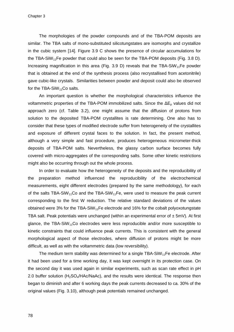
Chapter 3
78
The morphologies of the powder compounds and of the TBA-POM deposits are
similar. The TBA salts of mono-substituted silicotungstates are isomorphs and crystallize
in the cubic system [14]. Figure 3.9 C shows the presence of circular accumulations for
the TBA-SiW11Fe powder that could also be seen for the TBA-POM deposits (Fig. 3.8 D).
Increasing magnification in this area (Fig. 3.9 D) reveals that the TBA-SiW11Fe powder
that is obtained at the end of the synthesis process (also recrystallised from acetonitrile)
gave cubic-like crystals. Similarities between powder and deposit could also be observed
for the TBA-SiW11Co salts.
An important question is whether the morphological characteristics influence the
voltammetric properties of the TBA-POM immobilized salts. Since the ∆Ep values did not
approach zero (cf. Table 3.2), one might assume that the diffusion of protons from
solution to the deposited TBA-POM crystallites is rate determining. One also has to
consider that these types of modified electrode suffer from heterogeneity of the crystallites
and exposure of different crystal faces to the solution. In fact, the present method,
although a very simple and fast procedure, produces heterogeneous micrometer-thick
deposits of TBA-POM salts. Nevertheless, the glassy carbon surface becomes fully
covered with micro-aggregates of the corresponding salts. Some other kinetic restrictions
might also be occurring through out the whole process.
In order to evaluate how the heterogeneity of the deposits and the reproducibility of
the preparation method influenced the reproducibility of the electrochemical
measurements, eight different electrodes (prepared by the same methodology), for each
of the salts TBA-SiW11Co and the TBA-SiW11Fe, were used to measure the peak current
corresponding to the first W reduction. The relative standard deviations of the values
obtained were 3% for the TBA-SiW11Fe electrode and 16% for the cobalt polyoxotungstate
TBA salt. Peak potentials were unchanged (within an experimental error of ± 5mV). At first
glance, the TBA-SiW11Co electrodes were less reproducible and/or more susceptible to
kinetic constraints that could influence peak currents. This is consistent with the general
morphological aspect of those electrodes, where diffusion of protons might be more
difficult, as well as with the voltammetric data (low reversibility).
The medium term stability was determined for a single TBA-SiW11Fe electrode. After
it had been used for a time working day, it was kept overnight in its protection case. On
the second day it was used again in similar experiments, such as scan rate effect in pH
2.0 buffer solution (H2SO4/HAc/NaAc), and the results were identical. The response then
began to diminish and after 6 working days the peak currents decreased to ca. 30% of the
original values (Fig. 3.10), although peak potentials remained unchanged.

Functionalisation of GCE with TBA salts of Keggin-type silicotungstates
79
Conversely, the TBA-SiW11 modified electrode was fragile and, after one day, the W
peak currents began to decrease, pointing to a faster depletion of the adsorbed lacunary-
TBA salt from the electrode surface. This may be related to the observed higher crystal
size for TBA- SiW11, leading to greater mechanical fragility or to a lower stability of this
anion in the pH conditions used, in comparison with the metal substituted anions.
-1.0 -0.8 -0.6 -0.4 -0.2 0.0 0.2 0.4
2 µA
E / V vs. Ag/AgCl
Figure 3.10. Cyclic voltammograms for immobilized TBA- SiW11Fe on the GCE (same conditions
as in Fig. 3.3), (a) first; (b) second and (c) sixth working day.
3.3.2.3. Application of the TBA-SiW 11Fe modified electrode in the reduction of nitrite
Concerning the applicability of a POM species as reduction electrocatalyst, it is
convenient that the reduced form, which is the catalytic mediator, can provide a large
number of electrons at a suitable potential and not too negative because of interference
from H2 evolution. As was seen previously for the functionalised electrodes, there was no
significant difference between the E1/2 values for the first W reduction process of the
lacunary and its metal substituted species. More interesting is the fact that the potentials
for the metal-substituted TBA-POM modified electrodes were less negative than the
values for the corresponding aqueous soluble anions (cf. Tables 3.1 and 3.2). Therefore,
the mediation of a reaction such as the reduction of nitrite might be favoured for the metal-
substituted TBA-POM modified electrodes. Consequently, the TBA-SiW11Fe electrode
was chosen for preliminary tests as a mediator for the electroreduction of nitrite in pH 2.0
H2SO4 solutions.
(c)
(b)
(a)

Chapter 3
80
For nitrite, one difficulty that comes up is which are the actual reactive species in
acidic solution. Equations (1) and (2) suggest that HNO2 and/or NO should be the reactive
species, at least up to pH 3.3 [15,16]. HNO2 disproportionates in fairly acidic solutions,
even though the rate of this process is known to be low [15,16]. It has been claimed that
nitrous acid should be the reactive form of nitrite between pH 2 and 8 in the case of the
iron-substituted polyoxotungstates [17].
HNO2 H+ + NO2- (3.1)
3HNO2 H+ + NO3
- + 2NO + H2O (3.2)
Figure 3.11 presents voltammograms for the TBA-SiW11Fe modified electrode, in
the absence and in the presence of increasing concentrations of nitrite, in the interval
[0 - 0.09 mM], at 20 mV s-1.
-0.8 -0.6 -0.4 -0.2 0.0 0.2 0.4
4
1
1 µA
E / V vs. Ag/AgCl
0.000 0.005 0.010 0.015 0.0200
2
4
6
8
10
I pc /
µA
[NaNO2] / mM
Figure 3.11. Catalytic activity of immobilised TBA-SiW11Fe in the presence of different amounts of
nitrite. Cyclic voltammograms obtained in the absence and in the presence of increasing
concentrations of nitrite, in the interval [0 - 0.09 mM]: a) 0; b) 0.01; c) 0.04 and d) 0.09 mM. Inset:
plot of the catalytic peak current at -0.6 V vs. the concentration of nitrite. Experimental conditions:
pH 2.0 buffer solution (H2SO4/HAc/NaAc), ν = 20 mV s-1.
A solution of nitrite with the same concentrations does not present any reduction
signals. As Fig. 3.11 depicts, for increasing concentrations of nitrite in solution the peak

Functionalisation of GCE with TBA salts of Keggin-type silicotungstates
81
current of the first W reduction process (ca.-0.6V) increased whereas the corresponding
oxidation current decreased. This is typical for a reduction process mediated by a
reduction catalyst. The following equations present the possible overall process [16].
SiW11VIFe(H2O)O39
5- + 2e- + 4H+ → H4SiW2
VW9VIFe(H2O)O39
3- (3.3)
H4SiW2VW9
VIFe(H2O)O393-
+ n HNO2 → SiW11VIFe(H2O)O39
5- + n N products (3.4)
The inset in Fig. 3.11 shows a plot of the catalytic peak current at -0.6 V vs. the
concentration of nitrite. A linear range could only be defined for a nitrite concentration
below 0.02 mM. These results show that TBA-SiW11Fe salts immobilised on a GCE is a
mediator for the reduction of nitrite, as reported for this anion in aqueous solution (e.g.
[17,18]).
A similar behaviour was observed for SiW11Fe in aqueous solution. Curves (a-d) in
Figure 3.12 show the electrochemical responses for an NO2- concentration of 0, 1.00, 2.00
and 3.00 mM, obtained in H2SO4 aqueous solution (pH 2.0), at the scan rate of 20 mV s-1.
-0.8 -0.6 -0.4 -0.2 0.0 0.2 0.4
4
1
10 µA
E / V vs. Ag/AgCl
0.0 0.5 1.0 1.5 2.00
5
10
15
20
25
I pc /
µA
[NaNO2] / mM
Figure 3.12. Catalytic activity of the water soluble K-SiW11Fe anion in the presence of different
amounts of nitrite in aqueous solution. Cyclic voltammograms obtained in the absence and in the
presence of increasing concentrations of nitrite, in the interval [0 – 3.00 mM]: a) 0; b) 1.00; c) 2.00
and d) 3.00 mM. Inset: plot of the catalytic peak current at -0.6 V vs. the concentration of nitrite.
Experimental conditions: pH 2.0 buffer solution (H2SO4/HAc/NaAc), ν = 20 mV s-1.

Chapter 3
82
At pH 2.0, the catalytic currents increased with increase of nitrite concentration, as
shown in the inset. The linear range could be observed for a concentration of nitrite up to
2.0 mM. This shows that the reduced forms of the heteropolyanion react with the added
nitrite.
However, for some TBA-SiW11Fe modified electrodes, the total recovery of the initial
electrode condition was not possible. At the final of the electrocatalysis experiments the
electrode surface became partially depleted in microcrystallites (optical examination) and
the original voltammogram could not be restored.
In the present experimental conditions, nitrite reduction is not mediated by the
lacunary SiW11 (homogeneous reduction) [17]. It appears that the presence of the iron
substituting metal in the polyanion structure is essential for catalysis. However, there are
studies of the catalytic response of SiW11Fe, towards the reduction of nitrite pointing to the
extreme sensitivity, either in solution or immobilized on several electrodes, to supporting
electrolyte and pH. [15,16].
The electrocatalytic properties of the TBA-SiW11Co modified electrodes were also
tested for the reduction of nitrite. However, no effect was observed on the cyclic
voltammograms of this modified electrode although SiW11Co presents the tungsten
reduction and oxidation peaks at almost the same potential as the SiW11Fe.
3.5. Conclusions
The preparation of glassy carbon electrodes modified by the adsorbed hybrid salts
TBA-SiW11, TBA-SiW11Fe and TBA-SiW11Co, using solvent evaporation, was proved to be
simple and fast. Reproducible and stable electrodes were produced and their
voltammetric characteristics could be studied in different experimental conditions.
The results highlighted that:
• All modified electrodes consisted of a rather thick layer (ca. micrometer thick) of
the TBA-silicotungstate and could be produced by the single-drop solvent evaporation
method, from acetonitrile solutions. The salts deposited on the functionalised hybrid
electrodes showed a relatively high crystallinity.
• For all immobilized TBA-silicotungstates the W redox processes were diffusion-
controlled and, in fact, the first W reduction process was accompanied by the uptake of
protons diffusing from the acidic solution into the adsorbed hybrid layer. Further, the first

Functionalisation of GCE with TBA salts of Keggin-type silicotungstates
83
W reduction process, for all modified electrodes, was thermodynamically favoured
compared to what occurs with the corresponding water soluble polyanions.
• For future applications of the TBA-silicotungstate modified electrodes, namely in
electrocatalysis, two aspects may be of relevance: i) the specific role of the substituting
metals, either the potential of the W waves or on the electrocatalysis of nitrite, or other
species, ii) improvement of the mechanical stability of the modified electrodes under
catalysis working conditions.

Chapter 3
84
3.6. References
[1] M. I. Prodromidis, P. G. Veltsistas, C. E. Efstathiou, M. I. Karayannis, Electroanalysis 13 (2001)
960.
[2] H. M. Carapuça, M. S. Balula, A. P. Fonseca, A. M. V. Cavaleiro, J. Solid State Electrochem. 10
(2006) 10.
[3] M. Sadakane M, E. Steckhan, Chem. Rev. 98 (1998) 219.
[4] A. Muller, L. Dloczick, E. Diemann, M. T. Pope, Inorg. Chim. Acta 257 (1997) 231.
[5] M. Sadakane, E. Stechan, J. Mol. Catal. A: Chem. 114 (1996) 221.
[6] F. A. R. S. Couto, A. M. V. Cavaleiro, J. D. Pedrosa de Jesus, J. E. J. Simão, Inorg. Chim.Acta
281 (1998) 225.
[7] J. Kim, A. A. Gewirth, Langmuir 19 (2003) 8934.
[8] J. E. Toth, F. C. Anson, J. Electroanal. Chem. 256 (1988) 361.
[9] M. T. Pope, Heteropoly and Isopoly Oxometalates, Spring Verlag, 1983.
[10] A. J. Bard, L. R. Faulkner, Electrochemical Methods, Wiley, 2001.
[11] L.Cheng, H. Sun, B.Liu, J.Liu, S.Dong, J.Chem. Soc. Dalton Trans. (1999) 2619.
[12] X. L. Wang, E. B. Wang, Y. Lan, C. W. Hu, Electroanalysis 14 (2002) 1116.
[13] P. Wang, X. Wang, X. Jing, G. Zhu, Anal. Chim. Acta 424 (2000) 51.
[14] S. Balula, PhD Thesis, University of Aveiro, 2003.
[15] B. Keita, F. Girard, L. Nadjo, R. Contant, R. Belghiche, M. Abbessi, J. Electroanal. Chem. 508
(2001) 70.
[16] S. Dong, X. Xi, M. Tian, J. Electroanal. Chem. 385 (1995) 227.
[17] J. E. Toth, F. C. Anson, J. Am. Chem. Soc. 111 (1989) 2444.
[18] C. Rong, F. C. Anson, Inorg. Chim. Acta 242 (1996) 11.

CHAPTER 4
NOVEL POLY(HEXYLMETHACRYLATE)
COMPOSITE CARBON ELECTRODES
MODIFIED WITH TBA SALTS OF
KEGGIN PHOSPHOTUNGSTATES

Chapter 4
86
NOVEL POLY(HEXYLMETHACRYLATE) COMPOSITE CARBON ELECTRODES MODIFIED WITH TBA
SALTS OF KEGGIN PHOSPHOTUNGSTATES 85
4.1. Introduction 87
4.2. Experimental 88
4.2.1. Reagents and solutions 88
4.2.2. Instrumentation and methods 88
4.2.3. Preparation of the unmodified and modified CPEs 89
4.3. Characterization of carbon paste electrodes CPE1 and CPE2 90
4.4. Voltammetric behaviour of POM-CPE1 and POM-CPE2 92
4.5. Stability and surface renewal of POM modified CPEs 96
4.6. Conclusions 97
4.7. References 99

Novel poly(hexylmethacrylate) CPEs with phosphotungstates
87
4.1. Introduction
Over recent decades, carbon paste, i.e., a mixture of carbon (graphite) powder and
a binder (pasting liquid), has become one of the most popular electrode materials used for
electrode preparation. Such a position can be attributed to the gathering of many
physicochemical and electrochemical properties of this carbon-like substrate and its easy
of preparation [1-3]. Carbon paste electrodes (CPE) are composite electrodes because
they result from the combination of two or more materials and they have been widely
applied in electrochemistry owing to their many advantages. Besides being easy to
prepare and handle they are inexpensive, have low background currents and surface
renewal is rapid [3,4].
A number of reviews have been exclusively devoted to CPEs [1-6]. Presently, CPEs
represent one of the most frequent types of working electrodes. The large majority of
CPEs involve pastes made with insulating liquids (paraffin oil, silicon oil, and others). The
basic requirements for a pasting liquid are its lack of solubility in the solution under
measurement, a low vapour pressure to ensure both mechanical stability and long
lifetime, and in the case of voltammetric and amperometric applications, its
electrochemical inactivity in the potential window of interest. In contrast to the relatively
complicated modifications of solid substrates, carbon pastes can be modified simply to
obtain quantitatively new sensors with desired, often predefined, properties [2,3].
The present work concerns novel carbon composite electrodes modified with tetra-
butylammonium salts of [PW11O39]7- and [PW11CoII(H2O)O39]
5-, and a new easy way to

Chapter 4
88
immobilize these POMs by bulk or surface film modification. Bulk modification was done
by mixing the POM salts directly with the carbon paste (classified as CPE1). For surface
modification, a drop of a mixture of graphite and poly(hexylmethacrylate) binder, with or
without tetra-butylammonium salts of lacunary and mono-substituted POM anions is
deposited on the top of the surface of a normal carbon-paste electrode (graphite/mineral
oil). These modified electrodes will be referred to in this chapter as CPE2.Comparison with
the electrochemical behaviour of the polyoxoanion in the electrodes and in aqueous
solution was also carried out. To our knowledge, this is the first report of fabrication of a
surface-modified carbon composite electrode using poly(hexylmethacrylate) binder.
4.2. Experimental
4.2.1. Reagents and solutions
Sulphuric acid (Fluka), acetic acid (Pronalab), sodium acetate (Carlo Erba),
poly(hexylmethacrylate) solution (MW 400,000 in toluene - Aldrich), mineral oil (Fluka),
potassium hexacyanoferrate (III) (Merck), potassium chloride (Merck) and graphite
powder (Sigma Aldrich) were used as received. The tetra-butylammonium salts of the α-
Keggin phosphotungstates [(C4H9)4N]4H3[PW11O39] (TBA-PW11) and
[(C4H9)4N]4H[PW11CoII(H2O)O39]·H2O, (TBA-PW11Co) were prepared as described in
Chapter 2. Electrolyte solutions for voltammetry were prepared using ultra-pure water
(resistivity 18.2 MΩ cm at 25°C, Direct-Q 3 UV system, Millipore). Solutions within the pH
range 2.0-3.0 were prepared by mixing appropriate amounts of a 0.01 M H2SO4 solution
with a 0.10 M CH3COOH/NaCH3COO buffer (pH = 4.6). Potassium hexacyanoferrate (III)
solutions (1.0 mM) were prepared dissolving the appropriate amount of K3[Fe(CN)6] in 1.0
M KCl.
4.2.2. Instrumentation and methods
Electrochemical experiments were carried out as referred to in Chapter 3,using a
carbon paste electrode, CPE, inserted into a CPE cavity of diameter 3 mm (BAS, MF-

Novel poly(hexylmethacrylate) CPEs with phosphotungstates
89
2010). For pH measurements the same instrument was used as referred previously in
Chapter 3.
4.2.3. Preparation of the unmodified and modified C PEs
Figure 4.1 shows a schematic representation of electrode preparation. The carbon
paste electrode without bulk modification (CPE1) was fabricated as follows. A mass of 1.0
g of graphite powder and 0.5 mL of mineral oil were mixed in an agate mortar and pestle
to achieve a homogeneous mixture. A portion of this paste was then packed into the
cavity of the carbon paste electrode body and the surface was smoothed on a piece of a
weighing paper. POM bulk-modified carbon paste electrodes (POM-CPE1) were prepared
by substituting a corresponding amount of the graphite powder (10% mass ratio of the
modifier relative to the carbon powder) by TBA-PW11 (PW11-CPE1) or TBA-PW11Co
(PW11Co-CPE1).
For the poly(hexylmethacrylate) surface-modified carbon composite electrodes
(CPE2), two mixtures were prepared: (a) 0.75 g of graphite powder and 1.50 g of
poly(hexylmethacrylate) solution; (b) 0.75 g of graphite powder, 0.10 g of POM and 1.50 g
of poly(hexylmethacrylate) solution. A drop of 5 µL of each slurry was placed onto the
surface of an unmodified CPE prepared as described above and the solvent was allowed
to evaporate for about 20 min. If the drop spread outside the circular area of the carbon
paste the electrode assembly was rejected; thus, all electrodes employed had the same
surface area. Electrodes with film composition (a), abbreviated as CPE2, were used for the
characterization of the electrode in the absence of POMs. The POMs used for case (b)
were TBA-PW11 (PW11-CPE2) or TBA-PW11Co (PW11Co-CPE2).
An electrode surface activation step was done by cycling the potential 60 times,
between 0.0 V and -0.85 V, in 0.01 M H2SO4 at a scan rate of 100 mV s-1. This step was
needed to stabilise the electrodes and to obtain reproducible results, after which they
were ready to use.
Measurements were made at room temperature (~ 20 ºC). Solutions were degassed
with pure nitrogen for 5 minutes before the measurements and nitrogen-blanketed during
the measurements.

Chapter 4
90
Carbon Paste Electrode
CPE1
Graphite powder + mineral oil
Drop of graphite powderpoly(hexylmethacrylate) solution
POM-CPE1
CPE2 POM-CPE
2
Graphite powder + mineral oil + POM
Drop of graphite powder,poly(hexylmethacrylate) solution,
POM
Carbon Paste Electrode
CPE1
Graphite powder + mineral oil
Drop of graphite powderpoly(hexylmethacrylate) solution
POM-CPE1
CPE2 POM-CPE
2
Graphite powder + mineral oil + POM
Drop of graphite powder,poly(hexylmethacrylate) solution,
POM
Figure 4.1. Schematic representation indicating the components used in electrode preparation.
4.3. Characterization of carbon paste electrodes CP E1 and CPE 2
Hexacyanoferrate electroactive species were selected to evaluate the performance
of the prepared carbon paste electrodes CPE1 and CPE2. A more reversible
voltammogram indicates faster electrode kinetics and better access to the electrode and a
greater available surface area should result in higher peak currents. Fig. 4.2 shows the
electrochemical response of CPE1 and CPE2 in 1.0 mM K3[Fe(CN)6] + 1.0 M KCl solution.
A slight increase in the background current response at CPE2 is visible with respect to
CPE1. On the other hand, the peak current for the [Fe(CN)6]3-/4- redox couple is
significantly higher (increase >115%) at CPE2. The poly(hexylmethacrylate)-graphite

Novel poly(hexylmethacrylate) CPEs with phosphotungstates
91
electrode surface may have more exposed graphite particles, and possibly additional
porosity or roughness, leading to a higher available area for electrode reaction. The peak-
to-peak separations (∆Ep) were 76 mV for the CPE1 and 170 mV for CPE2, indicating
quasi-reversible electron transfer processes, the increase for CPE2 attributed to slower
kinetics.
-0.6 -0.4 -0.2 0.0 0.2 0.4 0.6 0.8
10 µA
c
ba
E / V vs. Ag/AgCl
Figure 4.2. Cyclic voltammograms of (a) CPE1 and CPE2 in 1 M KCl electrolyte and, (b) CPE1 and
(c) CPE2 in a solution of 1 mM K3[Fe(CN)6] + 1 M KCl. Scan rate 20 mV s-1.
The relationship between Ip and ν, seen in Fig. 4.3 as lg (Ip/A) versus lg (ν/V s-1),
gave slopes close to 0.50 for both CPE1 and CPE2, the square root relationship between
cathodic peak current and scan rate indicating that the redox processes at CPE1 and
CPE2 are diffusion-controlled. In the timescale used (scan rates between 20-1000 mV s-1)
the values of E1/2 did not change significantly (<10%) with scan rate and the ratio of anodic
and cathodic peak currents was ca. 1.

Chapter 4
92
1.2 1.4 1.6 1.8 2.0 2.2 2.4 2.6 2.8 3.0
0.8
1.0
1.2
1.4
1.6
1.8
lg (
I pc /
µA)
lg (v / mV s-1) Figure 4.3. Plot of lg Ipc versus lg ν for () CPE1 and () CPE2 in a solution of 1 mM K3[Fe(CN)6] +
1 M KCl.
4.4. Voltammetric behaviour of POM-CPE 1 and POM-CPE 2
Generally, Keggin phosphotungstates are unstable in neutral and basic solutions [7].
Therefore, all studies with the electrodes modified with the TBA salts of the
phosphotungstates PW11 and PW11Co were performed in acidic aqueous solution.
Cyclic voltammograms of the dissolved lacunary PW11 anion and of the metal-
substituted PW11Co in acidic solutions show two reversible or quasi-reversible two-
electron waves at negative potentials, corresponding to the reduction of the tungsten
atoms [8,9]. In these anions, the tungsten reduction processes are accompanied by the
addition of protons to counterbalance the increase in the negative charge and, therefore,
the half-wave potentials of the W waves are pH-dependent.
The voltammetric features of the TBA-phosphotungstates immobilized in the carbon
paste electrode were similar to those observed in aqueous solution for the corresponding
anions in terms of the numbers of electrons transferred. However, the shape of the cyclic
voltammograms is a little different from those obtained for aqueous dissolved POMs, but
similar to those obtained for the TBA-silicotungstates immobilized by the droplet
methodology described in Chapter 3. Fig. 4.4 shows cyclic voltammograms for PW11Co-
CPE2 immersed in pH 2.0 aqueous solution (H2SO4/HAc/NaAc).

Novel poly(hexylmethacrylate) CPEs with phosphotungstates
93
-0.8 -0.6 -0.4 -0.2 0.0
I'
I
II'
II
1 µA
E / V vs. Ag/AgCl
Figure 4.4. Cyclic voltammograms for PW11Co-CPE2 immersed in pH 2.0 H2SO4/HAc/NaAc
aqueous solution at ν=50 mV s-1, inverting the scan direction after the first reduction peak (---) and
after the second reduction peak (―).
In the conditions used, two reversible or quasi-reversible two-electron waves were
observed with reduction peak potentials at – 482 and – 685 mV vs Ag/AgCl for PW11Co. In
the same conditions PW11 presented peaks at – 487 and – 685 mV. Redox peaks I-I’ and
II-II’ are attributed to two consecutive two-electron reduction processes of the tungsten
atoms, i.e. corresponding to the expected four-electron global reduction process, as was
obtained for these anions immobilized on GCEs by droplet evaporation [10] and for the
corresponding silicotungstates in previous work [8,11,12]. The first pair was always well-
defined but the resolution of the second couple was worse for higher pH values. The
reduction/oxidation peak of the substituting metal (CoIII/II) was not observed because Co(II)
is generally not electroactive within the potential window used from -0.85 to 0.0 V.
Electrochemical pre-treatment, consisting of scanning for 60 cycles, led to a better
definition of the cyclic voltammograms. This suggests that cycling leads to reorganization
and/or wetting of the layer containing the TBA-phosphotungstate salts, resulting in an
increase of the electron transfer rate from the electrode surface to the redox sites of the
polyanion.
Cyclic voltammograms at PW11-CPE1 and PW11-CPE2 in pH 2.0 H2SO4/HAc/NaAc
aqueous solution at scan rates from 20 to 1000 mV s-1 are shown in Fig. 4.5.

Chapter 4
94
-0.8 -0.6 -0.4 -0.2 0.0
2 µA
E / V vs. Ag/AgCl
-0.8 -0.6 -0.4 -0.2 0.0
2 µA
E / V vs. Ag/AgCl
Figure 4.5. Cyclic voltammograms for (a) PW11-CPE1, and (b) PW11-CPE2, immersed in pH 2.0
buffer solution (H2SO4/HAc/NaAc) at scan rates 20, 50, 100, 500, 750 and 1000 mV s-1.
Cathodic and anodic peak currents were proportional to the square root of scan rate
which means that the process is controlled by counter-ion diffusion (see below).
(b)
(a)

Novel poly(hexylmethacrylate) CPEs with phosphotungstates
95
The same behaviour was observed for the modified electrodes with TBA
silicotungstates salts adsorbed on GCE by droplet evaporation (see Chapter 3). The same
occurred for other electrodes modified with Keggin-type anions, such as with
H3[PMo12O40]·nH2O for higher scan rates (ν ≥ 100 mV s-1) [13] in a ceramic-carbon
electrode, for hexadecylpyridium phosphomolybdate hybrid material in a carbon paste
electrode [14], and for lacunary and Fe and Co metal substituted phosphotungstate TBA
salts adsorbed on GCE by droplet evaporation [10].
Table 4.1 presents voltammetric data for the first tungsten reduction process for the
immobilized TBA phosphotungstates. The results concerning the second reduction
process were not included due to the fact that peaks were not always well resolved. The
potentials for the first tungsten process at the PW11Co carbon paste electrodes were
almost 70 mV less negative than the corresponding polyoxoanion in aqueous solution.
This may demonstrate that the electron transfer at the tungsten – oxide cage structure is
thermodynamically favoured for this POM when it is immobilized in the carbon paste. For
the PW11, no significant changes were observed. Also, as a consequence of
immobilization, there were no substantial differences between the potential of the first
tungsten process upon metal substitution, in contrast to aqueous solutions [9]. A similar
behaviour was observed for these phosphotungstates immobilized by the droplet
evaporation method [10] and for the corresponding silicotungstates immobilized by the
same procedure in Chapter 3.
The cathodic peak potentials shifted slightly in the negative direction and the
corresponding anodic peak potentials to the positive direction with increasing scan rates,
leading to an increase of peak-to-peak separation (∆Ep). The fact that ∆Ep for the first W
reduction wave has a value of 29 mV for CPE1 (see Table 4.1), together with the linear
relation between peak currents and square root of scan rate alluded to above indicates a
2-electron counter-ion diffusion-controlled process (57/n mV for a reversible process). The
values of |Ep-Ep/2| are in agreement with this hypothesis. The values of ∆Ep for CPE2 are
larger which suggests kinetic constraints in the presence of the polymer in the matrix. This
could be due to a very thin film of the polymer remaining on top of parts of the graphite
particles, which reduces the ease of reduction or oxidation [15]. The mechanism will
involve successive additions of electrons and protons (for reduction), as has been
observed in non-aqueous solution and where it was also pointed out that there are
pronounced medium effects on the observed voltammetry [16].

Chapter 4
96
Table 4.1. Cyclic voltammetric data for the first W reduction processes in pH 2.0 buffer solution
(H2SO4/HAc/NaAc) at 50 mV s-1.
Electrode Epc* Epa
* ∆Ep* Epc - Ep/2* Ipc (µA) Epc# (aq)
PW11-CPE1 -470 -441 29 28 -0.40 -486
PW11Co-CPE1 -487 -458 29 29 -0.45 -548
PW11-CPE2 -487 -449 38 32 -0.72 -486
PW11Co-CPE2 -482 -425 57 34 -0.53 -548
* mV vs. Ag/AgCl; # Epc values for polyoxoanions in aqueous solution of pH 2.2, ν=100 mV s-1 [9]
Initial pre-treatment led to activation of the modified electrode in terms of electron
transfer between the electrode and the active redox sites of the TBA-phosphotungstates,
so it may be assumed that diffusion of H+(aq) from the solution to the immobilized
phosphotungstates is rate-determining.
The pH of the supporting electrolyte has an influence on the electrochemical
behaviour of POM-CPE. With increasing pH, the cathodic and anodic peak potentials are
shifted in the negative direction by 99 mV for PW11Co and by 62 mV per pH unit for PW11,
suggesting 2e-/3H+ (as noted before in [11]), and 2e-/2H+ processes, respectively, the
protons diffusing from the solution to the surface of the electrode to maintain charge
neutrality. For surface-confined processes, the amount of POM that is accessible for
reaction at an electrode surface can be determined, as in [17], but to do so in this case
would require knowledge of the diffusion coefficient of the counterion which it is not
feasible to ascertain with meaningful accuracy, particularly given the non-uniformity of
composite electrode surfaces.
4.5. Stability and surface renewal of POM modified CPEs
Compared with polyoxometalate-modified electrodes fabricated by other methods,
POM-CPEs have certain advantages. One of the main attractions of using CPEs is that
the surface of the electrodes can be renewed after each use. Another is that the resulting
carbon paste electrode possesses high stability. Figure 4.6 shows, as an example, the
cyclic voltammograms for the PW11-CPE2 electrodes. When the potential range was
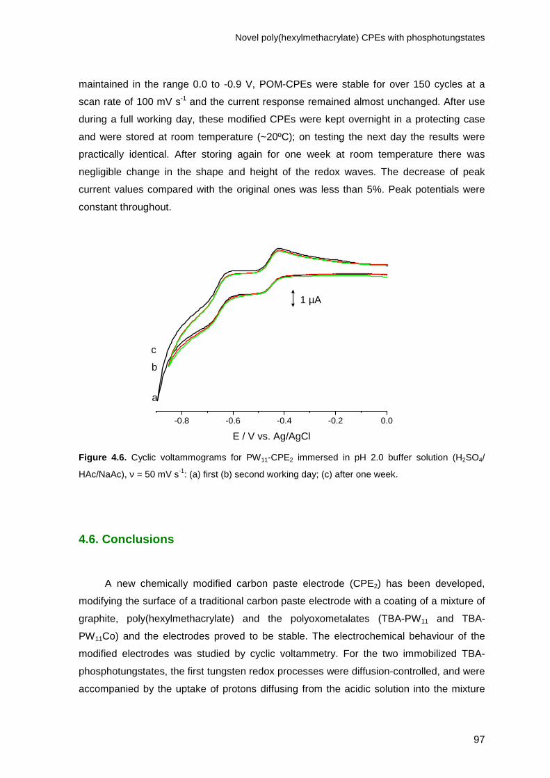
Novel poly(hexylmethacrylate) CPEs with phosphotungstates
97
-0.8 -0.6 -0.4 -0.2 0.0
c
b
a
1 µA
E / V vs. Ag/AgCl
maintained in the range 0.0 to -0.9 V, POM-CPEs were stable for over 150 cycles at a
scan rate of 100 mV s-1 and the current response remained almost unchanged. After use
during a full working day, these modified CPEs were kept overnight in a protecting case
and were stored at room temperature (~20ºC); on testing the next day the results were
practically identical. After storing again for one week at room temperature there was
negligible change in the shape and height of the redox waves. The decrease of peak
current values compared with the original ones was less than 5%. Peak potentials were
constant throughout.
Figure 4.6. Cyclic voltammograms for PW11-CPE2 immersed in pH 2.0 buffer solution (H2SO4/
HAc/NaAc), ν = 50 mV s-1: (a) first (b) second working day; (c) after one week.
4.6. Conclusions
A new chemically modified carbon paste electrode (CPE2) has been developed,
modifying the surface of a traditional carbon paste electrode with a coating of a mixture of
graphite, poly(hexylmethacrylate) and the polyoxometalates (TBA-PW11 and TBA-
PW11Co) and the electrodes proved to be stable. The electrochemical behaviour of the
modified electrodes was studied by cyclic voltammetry. For the two immobilized TBA-
phosphotungstates, the first tungsten redox processes were diffusion-controlled, and were
accompanied by the uptake of protons diffusing from the acidic solution into the mixture

Chapter 4
98
containing the POMs. Compared with other types of POM-modified electrode, CPEs
present the advantages of high stability due to the insolubility of the organic-inorganic
hybrid salts of POMs in aqueous solution and the affinity of the organic part ((C4H9)4N)+)
toward the paste which is important for practical applications. Modification using
poly(hexylmethacrylate) also slightly improves the electrode sensitivity for the same
amount of POMs.
Novel poly(hexylmethacrylate) CPEs with phosphotungstates
99
4.7. References
[1] I. Švancara, A. Walcarius, K. Kalcher, K. Vytřas, Cent. Eur. J. Chem. 7 (2009) 598.
[2] K. Kalcher, I. Švancara, R. Metelka, K. Vytřas, A. Walcarius, The Encyclopedia of Sensors, Vol.
4, American Scientific, Stevenson Ranch, 2006, 283 – 430.
[3] I. Švancara, K. Vytřas, K. Kalcher, A. Walcarius, J. Wang, Electroanalysis 21 (2009) 7.
[4] K. Kalcher, Electroanalysis 2 (1990) 419.
[5] K. Kalcher, J. M. Kauffmann, J. Wang, I. Švancara, K. Vytřas, C. Neuhold, Z. P. Yang
Electroanalysis 7 (1995) 5.
[6] K. Vytřas, K. Kalcher, I. Švancara, K. Schachl, E. Khaled, J. Ježková, J. Konvalina, R. Metelka
Electrochem. Soc. Proc. 18 (2001) 277.
[7] M.T. Pope, Heteropoly and Isopoly Oxometalates, Springer-Verlag, Berlin, 1983.
[8] B. Keita, L. Nadjo, J. Electroanal. Chem. 243 (1988) 87.
[9] F.A.R.S. Couto, A.M.V. Cavaleiro, J.D. Pedrosa de Jesus, J.E.J. Simão, Inorg. Chim. Acta 281
(1998) 225.
[10] H.M. Carapuça, M.S. Balula, A.P. Fonseca, A.M.V. Cavaleiro, J. Solid State Electrochem. 10
(2006) 10.
[11] D.M. Fernandes, S.M.N. Simões, H.M. Carapuça, A.M.V. Cavaleiro, Electrochim. Acta 53
(2008) 6580.
[12] J.E. Toth, F.C. Anson, J. Electroanal. Chem. 256 (1988) 361.
[13] P. Wang, X. Wang, X. Jing, G. Zhu, Anal. Chim. Acta 424 (2000) 51.
[14] X.L. Wang, E.B. Wang, Y. Lan, C.W. Hu, Electroanalysis 14 (2002) 1116.
[15] M.M. Barsan, E.M. Pinto, M. Florescu, C.M.A. Brett, Anal. Chim. Acta 635 (2009) 71.
[16] S.X. Guo, A.W.A. Mariotti, C. Schlipf, A.M. Bond, A.G. Wedd, Inorg. Chem. 45 (2006) 8563.
[17] A. Balamurugan, S.M. Chen, J. Solid State Electrochem. 11 (2007) 1679.

Chapter 4
100

++
++
+++
++
++
+++
++
------ -
-- --
---- --
-
------ -
--
------ -
--
------ -
--
------ -
--
++
++
+++
++
++
+++
++
------ -
-- --
---- --
-
------ -
--
------ -
--
------ -
--
------ -
--
++
++
+++
++
++
+++
++
++++
++
+++
++
++
+++
++
++++
++++++
++
++
+++
++
++++
++++
++++
++
+++++
+++
++
------ -
-- --
---- --
-
------ -
--
------ -
--
------ -
--
------ -
--
------ -
--
------ -
--
----- -
-- ---- --
- --- --
--- --
-- --
- --
- --
- ------ -
--
------ -
--
----- -
-- ---- --
- --- --
--- --
-- --
- --
- --
-
------ -
--
------ -
--
----- -
-- ---- --
- --- --
--- --
-- --
- --
- --
-
------ -
--
------ -
--
----- -
-- ---- --
- --- --
--- --
-- --
- --
- --
-
------ -
--
------ -
--
----- -
-- ---- --
- --- --
--- --
-- --
- --
- --
-
------ -
--
------ -
--
----- -
-- ---- --
- --- --
--- --
-- --
- --
- --
-+
+
++
+++
++
++
+++
++
++++
++
+++
++
++
+++
++
++++
++++++
++
++
+++
++
++++
++++
++++
++
+++++
+++
++
------ -
-- --
---- --
-
------ -
--
------ -
--
------ -
--
------ -
--
------ -
--
------ -
--
----- -
-- ---- --
- --- --
--- --
-- --
- --
- --
- ------ -
--
------ -
--
----- -
-- ---- --
- --- --
--- --
-- --
- --
- --
-
------ -
--
------ -
--
----- -
-- ---- --
- --- --
--- --
-- --
- --
- --
-
------ -
--
------ -
--
----- -
-- ---- --
- --- --
--- --
-- --
- --
- --
-
------ -
--
------ -
--
----- -
-- ---- --
- --- --
--- --
-- --
- --
- --
-
------ -
--
------ -
--
----- -
-- ---- --
- --- --
--- --
-- --
- --
- --
-
CHAPTER 5
SELF-ASSEMBLY MULTILAYER FILMS
BASED ON KEGGIN-TYPE
POLYOXOTUNGSTATES AND
POLY(ETHYLENIMINE)

Chapter 5
102
SELF-ASSEMBLY MULTILAYER FILMS BASED ON KEGGIN-TYPE POLYOXOTUNGSTATES AND
POLY(ETHYLENIMINE) 101
5.1. Introduction 103
5.2. Experimental 104
5.2.1. Reagents and solutions 104
5.2.2. Instrumentation and methods 105
5.2.3. Preparation of self-assembly (PEI/POM)n films 106
5.3. Film formation 106
5.4. Characterization of multilayer (PEI/POM)n films deposited on quartz slides 107
5.5. Scanning electron microscopy characterization 111
5.6. Voltammetric behaviour of multilayer films 113
5.7. Permeability of multilayer films 120
5.8. Electrochemical impedance characterisation 124
5.9. Electrocatalytic properties of (PEI/POM) multilayer films 130
5.10. Conclusions 135
5.11. References 137

Self-assembly multilayer films based on polyoxotungstates and PEI
103
5.1. Introduction
In recent years, many techniques have been developed to fabricate composite films
since they can be used to design and build different types of molecular architecture.
Layer-by-layer (LbL) assembly has proven to be a promising technique for fabricating
uniform and ultrathin film devices by the alternate immersion of a substrate into solutions
containing the chosen oppositely-charged species [1,2].
Multilayers based on POMs, polyelectrolytes and conducting polymers have been
widely used, as already referred to in Chapter 1 [3-15]. However, there are only a few
reports using poly(ethylenimine) (PEI) as the polycation [16,17]. In most studies it is used
as the anchorage layer together with PSS [18,19]. Although they are extensively used,
only some reports can be found in the literature concerning the characterization of the
structure and charge transfer processes in these multilayer films.
Electrochemical impedance spectroscopy (EIS) has been successfully used to study
interfacial processes, in order to obtain information about the structure and changes that
may occur at the electrode-electrolyte interface, and about reaction mechanisms and
electrode kinetics [20]. It is an effective method to investigate the interfacial properties of
modified electrodes [21-23]. It is complementary to cyclic voltammetry that often allows
quantitative determination of kinetic and diffusion parameters [24]. Modification of
electrode substrates alters the features of the impedance spectra. Impedance methods
are also attractive because of the small sinusoidal potentials that are used, rather than the
wide potential window used in cyclic voltammetry. Thus, EIS has unique benefits for

Chapter 5
104
monitoring the formation processes of multilayer films and in the characterisation of the
films and their interfacial properties.
The present chapter concerns the fabrication of stable ultrathin films of lacunary
SiW11 and mono-substituted polyoxometalates PW11Fe, SiW11Fe and SiW11Co, with
poly(ethylenimine) (PEI) by the layer-by-layer self-assembly method. Growth of the
multilayer films adsorbed on a quartz slide was monitored by UV–Vis absorption
spectroscopy and the surface morphology of the thin films on a glassy carbon electrode
was examined by scanning electron microscopy (SEM). The electrochemical behaviour of
the immobilized polyanions and electron transfer to [Fe(CN)6]3-/4- and [Ru(NH3)6]
3+/2+ as
electrochemical probes was investigated by cyclic voltammetry. Additionally, the possible
application of some of the modified electrodes as a sensor for nitrite, iodate and/or
bromate reduction was tested.
Electrochemical impedance spectroscopy was used to characterize glassy carbon
electrodes modified with hybrid films composed of PEI and Keggin-type SiW11Fe using
K3[Fe(CN)6] and Cl3[Ru(NH3)6] as redox probes. ITO modified electrodes were also used
for comparison. Impedance spectra were analysed by fitting to equivalent electrical
circuits and the effect of the number of layers, and of the two redox probes used on the
spectra and on the charge transfer processes are discussed.
5.2. Experimental
5.2.1. Reagents and solutions
The potassium salts K8[SiW11O39]·13H2O, K5[SiW11FeIII(H2O)O39]·13H2O,
K6[SiW11CoII(H2O)O39]·12H2O and K4[PW11FeIII(H2O)O39]·6H2O were prepared as
described in Chapter 2.
Poly(ethylenimine) (MW = 50,000–100,000; 30 wt. % aqueous solution; branched,
consisting of tertiary, secondary and primary amino groups in the ratio of 25/50/25,
respectively) was purchased from Polysciences Europe GmbH and was used without
further treatment. Sodium chloride (Merck), potassium chloride (Merck), acetic acid
(Pronalab), sodium acetate (Carlo Erba), potassium ferricyanide (Merck),
hexaammineruthenium (III) chloride (Aldrich), sodium nitrite (Merck), sodium bromate
(Sigma-Aldrich), potassium iodate (Sigma-Aldrich), buffer solution pH 9 (0.05 M H3BO3,

Self-assembly multilayer films based on polyoxotungstates and PEI
105
0.05 M KCl, 0.022 M NaOH) (Merck) and other reagents were analytical grade and were
used as received.
The electrolyte used for electrochemical studies was prepared by mixing appropriate
amounts of the CH3COOH (0.1 M) and NaCH3COO (0.1 M) solutions to give a pH 4.0
solution. Potassium ferricyanide and hexammineruthenium (III) chloride solutions (1.0
mM) were prepared dissolving the appropriate amount of K3[Fe(CN)6] and [Ru(NH3)6]Cl3 in
1M KCl. Electrolyte solutions for voltammetry were prepared using ultra-pure water
(resistivity 18.2 MΩ cm at 25°C, Direct-Q 3 UV system, Millipore).
5.2.2. Instrumentation and methods
UV–vis absorption spectroscopy of the K-SiW11, K-SiW11Co, K-SiW11Fe and K-
PW11Fe aqueous solutions was performed using a quartz cell with 0.4 cm path length in a
Jasco V-560 UV-visible spectrophotometer. A set of 7 solutions of each compound (0.001-
0.05 mM) in 0.1 M acetate buffer (pH 4.0) was used to determine the isotropic molar
absorption coefficient. The absorbance of each solution was measured and a calibration
curve was obtained by plotting the values of absorbance vs. concentration. As the path
length is known (0.4 cm) the ε is determined using the slope and the Beer-Lambert law.
The UV–Vis absorption spectra of the multilayer films were recorded on quartz slides.
Scanning electron microscopy was conducted on an Analytical FE-SEM SU-70
Hitachi, UHR 1.0 nm/15 kV (1.6 nm/1 kV). The film preparation for the SEM evaluation
was performed on a glassy carbon electrode that was previously cut to fit the equipment.
A glassy carbon electrode, GCE, (3 mm diameter, BAS, MF-2012) was used as
working electrode, on which the multilayer films were formed. Indium tin oxide (ITO)
electrodes with geometric area of 0.50 cm2 (ITO on quartz slides) were also used as
substrate for comparison. The auxiliary and reference electrodes were a platinum wire
(7.5 cm, BAS, MW-1032) and Ag/AgCl (sat. KCl) (BAS, MF-2052), respectively.
Electrochemical experiments were carried out as described previously in Chapter 3.
Electrochemical impedance measurements were carried out using a Solartron 1250
Frequency Response Analyser, coupled to a Solartron 1286 Electrochemical Interface
(UK) controlled by ZPlot Software. The voltage perturbation was 10 mV rms over a
frequency range from 65 kHz to 0.01 Hz with 10 frequencies per decade, and integration
time 60 s. Impedance spectra were analysed by fitting to equivalent electrical circuits
using ZView Software (Scribner Associates, USA).

Chapter 5
106
5.2.3. Preparation of self-assembly (PEI/POM) n films
Films were prepared on glassy carbon electrodes, ITO electrodes and quartz slides.
Prior to coating, the GCE was conditioned by a polishing/cleaning procedure. The GCE
was successively polished with 1.0 µm diamond polishing compound (Metadi II, Buehler)
and aluminium oxide of particle size 0.3 µm (Buehler-Masterprep) on a microcloth
polishing pad (BAS Bioanalytical Systems Inc), then the electrode was rinsed with ultra-
pure water and finally sonicated, for 5 min, in an ultrasonic bath (Branson 2510). The
quartz slides and ITO electrodes were cleaned by placing them in a H2SO4/H2O2 (3:1)
(v/v) hot bath (~80º C) for 40 min and then in a H2O/H2O2/NH3 (5:1:1) (v/v/v) hot bath
(~80º C) for another 40 min. The cleaned quartz slides and ITO electrodes were rinsed
with ultra-pure water and dried under a flow of pure nitrogen.
After the cleaning step, the GCE, ITO electrodes or quartz slide were immersed in a
5 mg/mL (0,12 M) PEI solution (in pH = 9.0 buffer for SiW11Fe and PW11Fe; in pH = 4.0
acetate buffer for SiW11, SiW11Fe and SiW11Co) for 20 min. The GCE was then immersed
in a 0.3 mM POM solution (in pH = 4.0 acetate buffer) for 20 min. This process was
repeated until the desired number of bilayers of PEI/POM was obtained. Water rinsing and
nitrogen drying steps were performed after each immersion.
The solutions used for the film preparation were used immediately after their
preparation and degassed with pure nitrogen for at least 10 min.
Additionally, the influence of different concentrations of POMs was tested. The
effects of different deposition times was tested for the (PEI/SiW11Fe)n multilayers. All
measurements were made at room temperature (~20º C).
5.3. Film formation
Thin multilayer films of lacunary and mono-substituted Keggin-type
polyoxometalates (SiW11, SiW11Co, SiW11Fe or PW11Fe) and protonated
poly(ethylenimine) prepared by layer-by-layer self-assembly were deposited on glassy
carbon electrodes, ITO electrodes or on quartz slides, by alternate immersion in aqueous
solutions of PEI and of the chosen polyoxoanion.
The formation of the multilayer structure via alternate adsorption of cationic PEI and
anionic POM on a substrate is represented in Fig. 5.1. The influence of pH, concentration
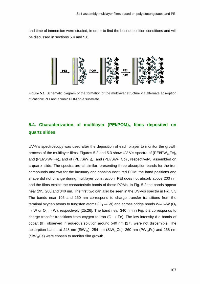
Self-assembly multilayer films based on polyoxotungstates and PEI
107
and time of immersion were studied, in order to find the best deposition conditions and will
be discussed in sections 5.4 and 5.6.
++
++
+++
++
++
+++
++
++
++
+++
++
++
+++
++
------ -
-- --
---- --
-
------ -
--
------ -
--
------ -
--
------ -
--
++
++
+++
++
++
+++
++
------ -
-- --
---- --
-
------ -
--
------ -
--
------ -
--
------ -
--
++
++
+++
++
++
+++
++
------ -
-- --
---- --
-
------ -
--
------ -
--
------ -
--
------ -
--
PEI POM PEI
POM+
+
++
+++
++
++
+++
++
++++
++
+++
++
++
+++
++
++++
++++++
++
++
+++
++
++++
++++
++++
++
+++++
+++
++
++
++
+++
++
++
+++
++
++++
++
+++
++
++
+++
++
++++
++++++
++
++
+++
++
++++
++++
++++
++
+++++
+++
++
------ -
-- --
---- --
-
------ -
--
------ -
--
------ -
--
------ -
--
------ -
--
------ -
--
----- -
-- ---- --
- --- --
--- --
-- --
- --
- --
- ------ -
--
------ -
--
----- -
-- ---- --
- --- --
--- --
-- --
- --
- --
-
------ -
--
------ -
--
----- -
-- ---- --
- --- --
--- --
-- --
- --
- --
-
------ -
--
------ -
--
----- -
-- ---- --
- --- --
--- --
-- --
- --
- --
-
------ -
--
------ -
--
----- -
-- ---- --
- --- --
--- --
-- --
- --
- --
-
------ -
--
------ -
--
----- -
-- ---- --
- --- --
--- --
-- --
- --
- --
-+
+
++
+++
++
++
+++
++
++++
++
+++
++
++
+++
++
++++
++++++
++
++
+++
++
++++
++++
++++
++
+++++
+++
++
------ -
-- --
---- --
-
------ -
--
------ -
--
------ -
--
------ -
--
------ -
--
------ -
--
----- -
-- ---- --
- --- --
--- --
-- --
- --
- --
- ------ -
--
------ -
--
----- -
-- ---- --
- --- --
--- --
-- --
- --
- --
-
------ -
--
------ -
--
----- -
-- ---- --
- --- --
--- --
-- --
- --
- --
-
------ -
--
------ -
--
----- -
-- ---- --
- --- --
--- --
-- --
- --
- --
-
------ -
--
------ -
--
----- -
-- ---- --
- --- --
--- --
-- --
- --
- --
-
------ -
--
------ -
--
----- -
-- ---- --
- --- --
--- --
-- --
- --
- --
-
PEI POM PEI
POM
Figure 5.1. Schematic diagram of the formation of the multilayer structure via alternate adsorption
of cationic PEI and anionic POM on a substrate.
5.4. Characterization of multilayer (PEI/POM) n films deposited on
quartz slides
UV-Vis spectroscopy was used after the deposition of each bilayer to monitor the growth
process of the multilayer films. Figures 5.2 and 5.3 show UV-Vis spectra of (PEI/PW11Fe)n
and (PEI/SiW11Fe)n and of (PEI/SiW11)n and (PEI/SiW11Co)n, respectively, assembled on
a quartz slide. The spectra are all similar, presenting three absorption bands for the iron
compounds and two for the lacunary and cobalt-substituted POM; the band positions and
shape did not change during multilayer construction. PEI does not absorb above 200 nm
and the films exhibit the characteristic bands of these POMs. In Fig. 5.2 the bands appear
near 195, 260 and 340 nm. The first two can also be seen in the UV-Vis spectra in Fig. 5.3
The bands near 195 and 260 nm correspond to charge transfer transitions from the
terminal oxygen atoms to tungsten atoms (Od → W) and across bridge bonds W–O–W (Ob
→ W or Oc → W), respectively [25,26]. The band near 340 nm in Fig. 5.2 corresponds to
charge transfer transitions from oxygen to iron (O → Fe). The low intensity d-d bands of
cobalt (II), observed in aqueous solution around 540 nm [27], were not discernible. The
absorption bands at 248 nm (SiW11), 254 nm (SiW11Co), 260 nm (PW11Fe) and 258 nm
(SiW11Fe) were chosen to monitor film growth.

Chapter 5
108
0.0
0.2
0.4
0.6
0.8
200 300 400 500 600 700 800
Wavelength / nm
Abs
orba
nce
0.0
0.1
0.2
0.3
0.4
0 2 4 6 8
Number of bilayersA
bsor
banc
e
0.0
0.2
0.4
0.6
200 300 400 500 600 700 800
Wavelength / nm
Abs
orba
nce
0.0
0.1
0.2
0.3
0.4
0.5
0 2 4 6 8 10Number of bilayers
Abs
orba
nce
Figure 5.2. UV-Vis absorption spectra of (a) (PEI/PW11Fe)n and (b) (PEI/SiW11Fe)n multilayers for
n = 0 – 8 adsorbed on a quartz slide. The insets in (a) and (b) show the absorbance at (a) 260 nm
and (b) 258 nm, as a function of n. The inset in (b) also shows the absorbance as a function of n for
different deposition times: () 20, (∆) 10 and (◊) 5 min.

Self-assembly multilayer films based on polyoxotungstates and PEI
109
0.0
0.2
0.4
0.6
200 300 400 500 600 700 800
Wavelength / nm
Abs
orba
nce
0.0
0.1
0.2
0.3
0.4
0 2 4 6 8Number of bilayers
Abs
orba
nce
0.0
0.2
0.4
0.6
200 300 400 500 600 700 800
Wavelength / nm
Abs
orba
nce
0.0
0.1
0.2
0.3
0.4
0 2 4 6 8
Number of bilayers
Abs
orba
nce
Figure 5.3. UV-Vis absorption spectra of (a) (PEI/SiW11)n and (b) (PEI/SiW11Co)n multilayers for
n = 0 – 7 adsorbed on a quartz slide. The insets in (a) and (b) show the absorbance at (a) 248 nm
and (b) 254 nm, as a function of n.
The insets in Fig. 5.2 and Fig. 5.3 show that the absorbance increases almost
linearly with the number of deposited layers, suggesting that the quantity of
polyoxometalate deposited per bilayer was approximately the same up to seven bilayers

Chapter 5
110
for SiW11, SiW11Co and PW11Fe and up to eight for SiW11Fe. With further increase in the
number of multilayers the absorbance increases less reaching a plateau. The inset in Fig.
5.2b also shows the absorbance of (PEI/SiW11Fe)n multilayers at 258 nm as a function of
n for three different deposition times. It can be seen that there is a considerable difference
between deposition times of 5, 10 or 20 min. Typically, in the literature, an adsorption time
between 5 and 20 min for each polyion is used although, in most cases, the major amount
of polyelectrolyte was in fact adsorbed within a few minutes [28-31]. Longer deposition
times (30 and 60 min) were also evaluated, besides the ones referred to above. However,
saturation was achieved after 20 min since the absorbance values at 258 nm did not
increase further for longer deposition times. Cyclic voltammetry tests were in agreement
with this, so, except when indicated, 20 min was the time used in the experiments
described below.
The surface coverage per layer, Γ, can be estimated from the spectra of the
multilayers, according to the Beer-Lambert law
Γ = Aλ/2mελ (5.1)
where Aλ is the absorbance at the specified wavelength, m is the number of layers and ελ
is the isotropic molar absorption coefficient (M-1 cm-1) [32]. In aqueous solution (acetate
buffer, pH 4) the isotropic molar absorption coefficients for SiW11, SiW11Co, SiW11Fe and
PW11Fe are ε248 = 7.66 x 10⁴ M-1 cm-1, ε254 = 7.27 x 10⁴ M-1 cm-1, ε258 = 8.84 x 10⁴ M-1 cm-1
and ε260 = 9.87 x 10⁴ M-1 cm-1, respectively. Using eqn.(1), this leads to values of the
surface coverage of 2.88 x 10⁻¹⁰ mol cm-2 for SiW11, 2.63 x 10⁻¹⁰ mol cm-2 for SiW11Co,
3.04 x 10⁻¹⁰ mol cm-2 for SiW11Fe and 2.72 x 10⁻¹⁰ mol cm-2 for PW11Fe for 20 min
deposition time. In the case of SiW11Fe, surface coverages of 2.15 x 10⁻¹⁰ mol cm-2 and
1.75 x 10⁻¹⁰ mol cm-2 were obtained for deposition times of 10 and 5 min. These values are
somewhat higher than the 1.00 x 10⁻¹⁰ mol cm-2 obtained for (PMo12/PDDA)n by Wang et
al [33] which they attributed to monolayer coverage. A possible explanation for the values
obtained being higher than expected may be the existence of diffuse scattering due to the
heterogeneity of the surface. It is known that when a beam is passed through a thin layer
of matter its intensity is generally diminished as a consequence of both absorption and
scattering. These scattering losses would give rise to a lower intensity of the transmitted
beam and thence higher calculated absorbance values and surface coverages.

Self-assembly multilayer films based on polyoxotungstates and PEI
111
5.5. Scanning electron microscopy characterization
SEM images provide information about the surface morphology and homogeneity of
the PEI layer and (PEI/POM)n multilayer films. Figure 5.4 shows SEM images of the PEI
layer on a glassy carbon electrode at two magnifications. In Fig. 5.4a it can be seen that
after PEI adsorption the surface is fully covered with small white bead-shaped domains of
different sizes. Amplification of the image reveals that the darker parts are also covered
with PEI (Fig. 5.4b).
(a) PEI layer ( ×××× 2000)
(b) PEI layer ( ×××× 8000)
Figure 5.4. Typical SEM micrographs for a PEI layer adsorbed on a glassy carbon electrode.
Figure 5.5 shows representative images upon adsorption of two bilayers of
(PEI/SiW11Co), (PEI/PW11Fe) and (PEI/SiW11Fe) at different magnifications. In the three
cases, a completely-covered surface is observed but the deposited film presents a
considerable number of cracks (Fig. 5.5 a, c and e). These may be due to the vacuum
system used in the SEM chamber and also to the high-energy beam; in fact, it was
possible to see the formation of cracks in places where they did not exist previously on
increasing the magnification. Higher magnification (Fig. 5.5 b, d and f) reveals the
presence of a high density of irregular shaped domains of small micrometric dimensions
underneath these cracks. The features of the SEM images were the same for larger
number of bilayers and the results for SiW11 were very similar. Although the pH values of
the solutions of POMs were different, no significant changes are observed on the
morphology of the deposited bilayers.

Chapter 5
112
(a) (PEI/SiW11Co)2 (× 2500) (b) (PEI/SiW11Co)2 (× 80000)
(c) (PEI/PW11Fe)2 (× 1800) (d) (PEI/PW11Fe)2 (× 35000)
(e) (PEI/SiW11Fe)2 (× 1800) (f) (PEI/SiW11Fe)2 (× 30000)
Figure 5.5. Representative SEM micrographs of (PEI/SiW11Co)2, (PEI/PW11Fe)2 and
(PEI/SiW11Fe)2 films on a glassy carbon electrode at different magnifications.

Self-assembly multilayer films based on polyoxotungstates and PEI
113
5.6. Voltammetric behaviour of multilayer films
All voltammetric results presented below were obtained using a concentration of 0.3
mM of POM for film preparation. Studies with electrodes obtained using 1 mM POM
solutions (SiW11Fe and PW11Fe) for the same deposition time did not show significant
changes in the peak currents. This suggests that, in this concentration range, the
concentration of POM has little effect on the amount of POM adsorbed in each layer and
that in fact, the determinant factor for higher adsorption of POM may be the amount of
available PEI rather than the POM concentration since higher concentrations of POM did
not led to higher peak currents.
In order to ensure reproducible results and as mentioned in section 5.2.3 on film
preparation, after each immersion the electrode was rinsed with ultra-pure water and dried
under a flow of nitrogen. Rinsing removes weakly attached, physically adsorbed
molecules, preparing the surface for the next adsorbed layer [31] and guarantees precise
increments in the thickness of the layer-by-layer self-assembled films.
To understand the electrochemical behaviour of (PEI/POM)n films, comparison with
the redox behaviour of the POMs in aqueous solution is important. The majority of the
voltammetric studies reported for lacunary and transition metal substituted Keggin-type
anions in aqueous solution have been performed in acidic media [34-37]. In these
conditions, all anions studied in this work presented two consecutive reversible or quasi-
reversible 2-electron waves at negative potentials, corresponding to the reduction of WVI
atoms as already observed in Chapter 3 and also referred in Chapter 1. The iron-
substituted polyanions presented another wave at a less negative potential due to the
redox process of FeIII/II. The four polyoxotungstates studied in different acidic aqueous
solutions, presented Epa and Epc values independent of scan rate, suggesting that the
electrode reactions are reversible; peak currents were proportional to the square root of
scan rate, indicating that the redox processes were controlled by diffusion, as referred
previously in Chapter 3.
Figure 5.6 shows cyclic voltammograms for single (PEI/SiW11) and (PEI/SiW11Co)
bilayers and Fig. 5.7 for single (PEI/PW11Fe) and (PEI/SiW11Fe) bilayers at different scan
rates at pH 4.0, which demonstrate that the electrochemical properties of the four POMs
studied are maintained in the multilayer films. Since PEI is not electroactive, its presence
is not reflected in the cyclic voltammograms. Under the conditions used, the cyclic
voltammograms of (PEI/SiW11) and (PEI/SiW11Co) bilayers only presented two quasi-
reversible two-electron reduction peaks which were observed at -711 and -876 mV for

Chapter 5
114
SiW11, -714 and -885 mV for SiW11Co vs. Ag/AgCl. These redox peaks are attributed to
two consecutive two-electron reduction processes of tungsten atoms, i. e. corresponding
to the expected four-electron global reduction process. For (PEI/PW11Fe) and
(PEI/SiW11Fe) bilayers, three reduction peaks were observed. The redox peaks
corresponding to the tungsten reductions were observed at -750 and -905 mV for SiW11Fe
and at -680 and -838 mV for PW11Fe vs. Ag/AgCl. The pair of peaks for the one-electron
reduction/oxidation of FeIII/II is also observed in the cyclic voltammograms of SiW11Fe and
PW11Fe at -163 and -171 mV, respectively. The reduction/oxidation peak of substituting
metal CoIII/II was not observed because Co(II) is not usually electroactive within the
potential window used from -1.0 to 0.0 V.
-1.0 -0.8 -0.6 -0.4 -0.2
2 µA
E (V) vs. Ag/AgCl
-1.0 -0.8 -0.6 -0.4 -0.2 0.0
1 µA
E (V) vs. Ag/AgCl
Figure 5.6. Cyclic voltammograms in CH3COOH/NaCH3COO buffer solution (pH 4.0) at different scan rates: 25, 50, 75, 100, 125, 150, 200, 250 and 300 mV s-1 for (a) (PEI/SiW11)1 and (b) (PEI/SiW11Co)1 bilayer films.

Self-assembly multilayer films based on polyoxotungstates and PEI
115
-1.0 -0.8 -0.6 -0.4 -0.2 0.0 0.2 0.4
2 µA
E (V) vs. Ag/AgCl
-1.0 -0.8 -0.6 -0.4 -0.2 0.0 0.2 0.4
2 µA
E (V) vs. Ag/AgCl
Figure 5.7. Cyclic voltammograms for (PEI/POM) bilayer films in CH3COOH/NaCH3COO buffer
solution (pH 4.0) at different scan rates: (a) 25, 50, 75, 100, 125, 150, 200 and 250 mV s-1 for
(PEI/SiW11Fe) and (b)10, 25, 50, 75 and 100 mV s-1 for (PEI/PW11Fe).
In the experimental timescale employed (scan rates in the range 10 to 100 mV s-1
for (PEI/PW11Fe), 25 to 250 mV s-1 for (PEI/SiW11Fe) and 25 to 300 mV s-1 for (PEI/SiW11)
and (PEI/SiW11Co) the values of peak potential changed only slightly with scan rate, and
the ratio of anodic to cathodic peak currents was close to 1.
It was found that the cathodic and anodic peak currents of the first W wave were
directly proportional to the scan rate, which indicates a surface-confined process [38]. This
behaviour has also been observed by S. Liu et al. for [Co4(H2O)2P4W30O112]16−,

Chapter 5
116
[Eu(H2O)P5W30O110]12− and [Na(H2O)P5W30O110]
14− [2] and by B. Xu et al. for
K6[P2W18O62]·14H2O [6] using the LbL methodology. Similar behaviour was also observed
for the Keggin type [SiW11Ni(H2O)O39]6- [39] deposited on the electrode by
electrodeposition with cysteamine. The number of electrons transferred in the tungsten
redox processes is obtained by comparison of the peak currents for the FeIII/II couple with
those of the first tungsten reduction process and indicates a 2-electron process (i.e. two
coincident one-electron WVI/V reductions). Note that the peak currents for the FeIII/II couple
are influenced by the slow kinetics of this process (the peak-to-peak separation is
substantially higher than for the first W wave), thus the Ip for the FeIII/II reduction is
certainly less than for a fully reversible process. In addition, the anodic/cathodic peak-to-
peak separation (∆Ep) for the tungsten waves was ca. 30–60 mV instead of zero, which
would have been expected for a reversible surface process. These higher values of ∆Ep
suggest kinetic constraints.
Comparison of the electrochemical behaviour of the multilayer (PEI/SiW11Fe) film
with that of the potassium salt of SiW11Fe in pH 4.0 aqueous solution (see Chapter 3)
shows that there are no significant differences in the peak potentials, but the peaks are
broader than in solution. This broadening may be related to the large coulombic repulsion
between the negative sites of highly-charged polyanions in the same layer, as suggested
in reference [40]. It also demonstrates that the PEI layers do not block electron transfers
between the immobilized anions of SiW11Fe. The potentials for the first tungsten process
at the SiW11 modified electrode are almost 70 mV more negative than the corresponding
polyoxoanion in aqueous solution (Epc = -643 mV at pH = 4.0). However, for SiW11Co the
potentials are similar (Epc = -730 mV in solution at pH = 4.0). This difference in both
modified electrodes is due to the fact that in aqueous solution there are substantial
differences between the potentials of the first tungsten process upon metal substitution as
seen in Chapter 3 and in reference [38], in contrast to what happens when POM are
immobilized, where the potentials of lacunary and mono-substituted POMs are practically
the same (see Chapter 3 and 4).
Cyclic voltammograms for (PEI/SiW11Co)n, (PEI/SiW11)n, (PEI/PW11Fe)n and
(PEI/SiW11Fe)n multilayer films with different numbers of layers are presented in Figures
5.8 and 5.9. In all cases, the cathodic peak potentials shift to more negative values by
approximately 10 to 30 mV and the anodic peak potentials shift to slightly more positive
values with an increase in the number of layers. Plots of peak current vs. the number of
bilayers (n), show linear growth up to n = 7 for both SiW11Co and SiW11, n = 5 for PW11Fe
and n = 6 for SiW11Fe. Above these numbers of bilayers, peak currents begin to show a

Self-assembly multilayer films based on polyoxotungstates and PEI
117
negative deviation from linearity, which can be ascribed to effects of film resistance, i.e.
difficulty of transferring electrons through the film to the electrode substrate. Although the
peaks for (PEI/SiW11)n multilayer films are not so well defined as for (PEI/SiW11Co)n, they
appear at the expected potentials and the system exhibits the same characteristics.
-1.0 -0.8 -0.6 -0.4 -0.2
1 µA
E (V) vs. Ag/AgCl
0.0
0.4
0.8
1.2
0.0 1.0 2.0 3.0 4.0 5.0 6.0 7.0 8.0Number of bilayers
I pc
/ µ
A
0.0
0.4
0.8
1.2
0.0 1.0 2.0 3.0 4.0 5.0 6.0 7.0 8.0Number of bilayers
I pc
/ µ
A
-1.0 -0.8 -0.6 -0.4 -0.2 0.0
0.5 µA
E (V) vs. Ag/AgCl
Figure 5.8. Cyclic voltammograms for (a) (PEI/SiW11)n and (b) (PEI/SiW11Co)n multilayer films in
CH3COOH/NaCH3COO buffer solution (pH 4.0) for n = 1 – 7, ν = 50 mV s-1. The insets show the
peak currents vs. the number of multilayers.

Chapter 5
118
0.0
0.2
0.4
0.6
0.8
0.0 1.0 2.0 3.0 4.0 5.0 6.0 7.0Number of bilayers
I pc
/ µ
A-1.0 -0.8 -0.6 -0.4 -0.2 0.0 0.2 0.4
0.2 µA
E (V) vs. Ag/AgCl
0.0
0.4
0.8
1.2
1.6
2.0
0.0 1.0 2.0 3.0 4.0 5.0 6.0Number of bilayers
I pc
/ µ
A
-1.0 -0.8 -0.6 -0.4 -0.2 0.0 0.2 0.4
0.5 µA
E (V) vs. Ag/AgCl
Figure 5.9. Cyclic voltammograms for (a) (PEI/SiW11Fe)n and (b) (PEI/PW11Fe) multilayer films in
CH3COOH/NaCH3COO buffer solution (pH 4.0) for n = 6 for PEI/SiW11Fe and 7 for PEI/PW11Fe,
ν = 10 mV s-1. The insets show the peak currents vs. the number of multilayers.
In order to gain more insight into the requisites for the good deposition of multilayer
films, the influence of two polycation solutions with different pH values on the growth
characteristics of PEI/SiW11Fe multilayers was studied. Different adsorption times of the
polycation PEI and polyanion SiW11Fe were also tested.
Self-assembly multilayer films based on polyoxotungstates and PEI
119
The effect of pH on the layer-by-layer self-assembly method is evident, but complex
[32]. Apart from any changes in the ionic strength of the buffer solutions used, a change in
pH may modify the charge density of polyelectrolytes due to protonation-deprotonation
equilibria: an increased charge density of the adsorbing polymer will favour thinner
adsorption layers, whereas increasing charge density at the surface will favour thicker
adsorbed layers [41]. Therefore, the effect of pH on layer-by-layer film growth is not clear
a priori. To study the pH effect, two 5mg/mL PEI solutions were used in LbL film
preparation of (PEI/SiW11Fe), one in a pH 9.0 and the other in a pH 4.0 buffer solution. No
differences in the peak potentials were observed and peak currents increased linearly with
the number of layers in both cases. However, the peak currents were lower when using
the modified electrodes prepared with the PEI solution at pH 4.0 than at pH 9.0, although
the peaks obtained were better resolved.
The influence of deposition time on the growth of multilayer films on the glassy
carbon electrodes was tested for (PEI/SiW11Fe) using different immersion times per
anionic or polycationic layer (60, 30, 20, 15 and 10 min). Since saturation was achieved
using 20 min deposition times only 20, 15 and 10 min will be discussed here. For these
three adsorption times, there was no difference in the peak currents up to the
(PEI/SiW11Fe)4 multilayer but differences became apparent for (PEI/SiW11Fe)5 and
subsequent multilayers. An adsorption time of 20 min results in the largest amount of
adsorbed material (higher peak currents). For 10 and 15 min adsorption times, after the
(PEI/SiW11Fe)6 multilayer, peak current saturation is obtained. Several studies indicate
that polyelectrolyte adsorption is a two-step process where most polymer chains are
anchored during a fast initial step and then the growth of the film slows down until the
surface charge becomes completely inverted [28-30,42]. This second step may take much
longer. Taking this into account, it is probable that the 10 and 15 min immersion times are
not sufficient to achieve total charge reversal with respect to the previous layer, thus
leading a smaller adsorption of the next layer and consequent lower peak currents.
Surface coverage can be calculated from cyclic voltammetry according to the
equation:
Γ = (4IpaRT) / (n2F2νA) (5.2)
where Ipa is the anodic peak current (amperes), n is the number of electrons transferred (2
in this case), ν is the scan rate (V s-1), A is the geometric area of the electrode (0.0725
cm2), R is the gas constant (8.314 J K-1 mol-1), T is the temperature (298K) and F is

Chapter 5
120
Faraday’s constant (96485 C mol-1) [40]. In order to obtain the surface coverage, peak
currents were plotted against scan rate (10 to 100 mV s-1 for SiW11Fe and PW11Fe and 10
to 300 mV s-1 for SiW11 and SiW11Co) and the value of Ipa/ν obtained was used to calculate
surface coverage using equation (5.2). This led to a surface coverage of 1.29 x 10⁻¹⁰ mol
cm-2 for PW11Fe, 1.09 x 10⁻¹⁰ mol cm-2 for SiW11Fe, 1.50 x 10⁻¹¹ mol cm-2 for SiW11 and
1.82 x 10⁻¹¹ mol cm-2 for SiW11Co.
Assuming a close geometric packing of POM clusters and the data from scanning
tunnelling microscopy observation of Keggin clusters deposited on a gold surface [43] to
estimate monolayer coverage, Wang et al [33] calculated a value of 1.25x10⁻¹⁰ mol cm-2.
Comparing this with our values of surface coverage obtained by cyclic voltammetry for
SiW11Fe and PW11Fe, ours corresponds to monolayer coverage. The values of surface
coverage obtained using, in the electrode preparation, a solution of PEI with pH = 4.0
indicate that in those cases (SiW11 and SiW11Co) a sub-monolayer coverage is achieved.
Nevertheless, the surface coverages estimated by UV-visible spectroscopy are somewhat
higher (2.72x10⁻¹⁰ mol cm-2 for PW11Fe, 3.04x10⁻¹⁰ mol cm-2 for SiW11Fe, 2.88x10⁻¹⁰ mol
cm-2 for SiW11 and 2.63x10⁻¹⁰ mol cm-2 for SiW11Co), but are calculated assuming that the
molar absorption coefficients of the polyoxometalates are the same in solution and in the
films, which is not certain. The surface coverages reported in the literature calculated by
cyclic voltammetry are usually lower than those obtained from UV-visible spectroscopy
[2,32].
5.7. Permeability of multilayer films
Electrochemistry can be employed to assess film permeability and as a sensitive
probe of structural changes in the (PEI/POM)n films. In particular, the passivating abilities
of different films can be compared using cyclic voltammetry via peak currents and
voltammogram shapes. Many groups have used the [Fe(CN)6]3-/4- redox couple to study
the permeability of multilayer films [2,16,44-46]; however, studies of electron transfer at
films containing polyoxometalates are few. Liu et al. showed that the permeability towards
these species can be tailored through the multilayer construction and deposition
conditions [2]. Also, Gao et al. investigated how the number of multilayer films influences
the shape of the cyclic voltammograms [16].
Cyclic voltammetry was also used to study the properties of the multilayer films
towards the negatively charged [Fe(CN)6]3-/4- and the positively charged [Ru(NH3)6]
3+/2+

Self-assembly multilayer films based on polyoxotungstates and PEI
121
redox probes. Electrostatic attraction between the multilayer surface and the redox probe
when they have opposite charges should facilitate the interfacial electron transfer process,
whereas repulsion when they have the same charge would make the electron transfer
reaction more difficult. A more reversible voltammogram indicates better access to the
electrode substrate, which should result in higher peak currents.
Figure 5.10 shows, as example, cyclic voltammograms of [Fe(CN)6]3-/4- at the
electrode modified with (PEI/SiW11Co)n for n = 1, 2, 4 and 6. These results show that for
an electrode coated with a single (PEI/SiW11Co) bilayer the cyclic voltammogram exhibits
quasi-reversible properties, indicating that the probe diffuses freely through the layer and
undergoes electron transfer at the electrode surface. Increasing the number of multilayers
from one to four leads to a decrease in peak currents and peak broadening and ultimately
to an electrode with plateau-shaped current characteristics (Fig. 5.10a). These
observations show that an increased number of multilayers leads to a decrease in the
number of hexacyanoferrate ions which reach the electrode substrate whenever the
terminal layer consists of negatively charged SiW11Co anion. This is attributable to
electrostatic repulsion of [Fe(CN)6]3-/4- by the external negatively charged SiW11Co anion.
When the outermost layer is the positively charged PEI the quasi-reversible properties in
the cyclic voltammogram of [Fe(CN)6]3-/4- are restored (Fig. 5.10b), due to the electrostatic
attraction of [Fe(CN)6]3-/4- from the terminal positively-charged PEI layer. The
voltammogram is similar to that of a bare glassy carbon electrode, and is independent of
film thickness (number of bilayers).

Chapter 5
122
a
0.0 0.1 0.2 0.3 0.4 0.5
2
43
1
2 µA
E (V) vs. Ag/AgCl
b
0.0 0.1 0.2 0.3 0.4 0.5
2
1
2 µA
E (V) vs. Ag/AgCl
Figure 5.10. Cyclic voltammograms of [Fe(CN)6]3-/4- (1 mM, 1 M KCl) ν = 100 mV s-1, at modified
electrodes with (a) (PEI/SiW11Co)n for (1) n = 1; (2) 2; (3) 4 and (4) 6; (b) 1 - (PEI/SiW11Co)6 and
2 - (PEI/SiW11Co)6/PEI.
When the positively charged [Ru(NH3)6]3+/2+ redox probe is used at the
(PEI/SiW11Co)n (with n = 1, 2 and 4) modified electrode, the changes observed are not so
significant (Fig. 5.11a). The cyclic voltammograms for n = 1 and 2 are almost identical and
there is a slight decrease in the peak currents and an increase in the peak-to-peak
separation on increasing the number of bilayers to four. However, after the addition of a
layer of PEI on the (PEI/SiW11Co)1 modified electrode (Fig. 5.11b), the peak current of
[Ru(NH3)6]3+/2+ decreases significantly and the peak-to-peak separation increases. This is

Self-assembly multilayer films based on polyoxotungstates and PEI
123
attributable to electrostatic repulsion of [Ru(NH3)6]3+/2+ by the positively charged PEI. The
same tests were performed for (PEI/PW11Fe) and (PEI/SiW11Fe) and the results were
identical.
The electrostatic attractions or repulsions have significant effects on the kinetics of
the redox reactions. With an increasing number of (PEI/POM) bilayers the peak current of
both redox probes decrease gradually, and the peak-to-peak separation increase, owing
to kinetic and/or thermodynamic constraints associated with increase film thickness.
-0.5 -0.4 -0.3 -0.2 -0.1 0.0 0.1 0.2
32 1
2 µA
E (V) vs. Ag/AgCl
a
b
-0.5 -0.4 -0.3 -0.2 -0.1 0.0 0.1 0.2
2
12 µA
E (V) vs. Ag/AgCl
Figure 5.11. Cyclic voltammograms of [Ru(NH3)6]3+/2+ (1 mM, 1 M KCl) ν = 100 mV s-1, at modified
electrodes with (a) (PEI/SiW11Co)n for (1) n = 1; (2) 2 and (3) 4; (b) 1 - (PEI/SiW11Co)1 and
2 - (PEI/SiW11Co)1/PEI.

Chapter 5
124
To test the reproducibility of these LbL modified electrodes five electrode
assemblies were prepared under identical conditions and the cyclic voltammograms
recorded in CH3COOH/NaCH3COO buffer solution (pH 4.0). The relative standard
deviation of the peak current for the first tungsten reduction wave was 14.9% for
(PEI/PW11Fe)n, 4.3% for (PEI/SiW11Fe)n, 3.8% for (PEI/SiW11Co)n and 4.6% for
(PEI/SiW11)n. Peak potentials did not change significantly. To test stability, modified
electrodes were used all day long and kept overnight in their protecting case for 1, 3 or 8
days. No change in the shape and height of the redox waves was observed. Fig. 5.12
shows, as an example, the cyclic voltammograms for the (PEI/SiW11Co)7 electrode.
-1.0 -0.8 -0.6 -0.4 -0.2 0.0
1 µA
E (V) vs. Ag/AgCl
Figure 5.12. Cyclic voltammograms for (PEI/SiW11Co)7 multilayer films in CH3COOH/NaCH3COO
buffer solution (pH 4.0), ν = 25 mV s-1 at first (black), second (red) and eighth working day (green).
5.8. Electrochemical impedance characterisation
Electrochemical impedance spectroscopy can be used to examine the electrical
properties of the multilayer assembly which should change as it is built up and provide
information which is complementary to that of cyclic voltammetry during the step
deposition of the charged PEI and POM layers. Impedance spectra were recorded after
the deposition of each layer of PEI and POM in order to investigate the effect of the
structure and thickness of the multilayer on the overall interfacial properties in 3 mM

Self-assembly multilayer films based on polyoxotungstates and PEI
125
K3[Fe(CN)6]/0.1 M KCl and in [Ru(NH3)6]Cl3/0.1M KCl at 250 mV and -200 mV vs.
Ag/AgCl, respectively.
Figures 5.13 and 5.14 show impedance spectra at glassy carbon electrodes with
different numbers of PEI/POM bilayers using [Fe(CN)6]3-/4- and [Ru(NH3)6]
3+/2+ redox
probes, respectively. Changes can be clearly seen in the spectra during the stepwise
formation of the multilayer assemblies. The impedance spectra comprise a semicircle in
the high frequency range that corresponds to the kinetic control of the charge-transfer
process and a linear part at lower frequencies, attributable to diffusion control. The
diameter of the semicircle increases with an increasing number of PEI/POM bilayers,
which can be ascribed to the increase in film thickness and change in the apparent charge
transfer resistance.
For the glassy carbon electrode (GCE) covered with only one layer of the positively-
charged PEI, tested in the K3Fe(CN)6 solution, no semicircle was observed. A similar
behavior was found for GCE and GCE/(PEI/POM)1 in the solution containing
[Ru(NH3)6]3+/2+. This suggests that the semicircle region is very small and the spectrum is
dominated by the Warburg impedance, and thence diffusion control, over nearly the whole
range of frequencies examined.
0.0 0.5 1.0 1.5 2.0 2.50.0
0.5
1.0
1.5
2.0
2.5
0.26 Hz
Fe(CN)6
3-
GCE GCE/(PEI/POM)
1
GCE/(PEI/POM)2
GCE/(PEI/POM)3
GCE/(PEI/POM)4
- Z
" /
kΩ c
m2
Z ' / kΩ cm2
Figure 5.13. Complex plane impedance spectra of different modified electrodes in the presence of
3 mM K3Fe(CN)6 at +250 mV. Lines indicate equivalent circuit fitting.

Chapter 5
126
0.00 0.01 0.02 0.03 0.04 0.05 0.060.00
0.01
0.02
0.03
0.04
0.05
0.06
- Z
" /
kΩ c
m2
Z ' / kΩ cm2
0.0 0.1 0.2 0.3 0.4 0.50.0
0.1
0.2
0.3
0.4
0.5
0.26 Hz
Ru(NH3)6
3+ GCE GCE/(PEI/POM)
1
GCE/(PEI/POM)2
GCE/(PEI/POM)3
GCE/(PEI/POM)4
- Z
" /
kΩ c
m2
Z ' / kΩ cm2
Figure 5.14. Complex plane impedance spectra of different modified electrodes in the presence of
3 mM Ru(NH3)6Cl3 at - 200 mV, with amplitude of 10 mV in the frequency range from 65 kHz to
0.01 Hz. In the inset a magnification of the spectra is presented. Lines indicates equivalent circuit
fitting.
Quantitative information can be obtained by analysis using appropriate electrical
equivalent circuits, Fig. 5.15, and extraction of the electrical parameters. The fitting circuit
in Fig.5.15a is a typical Randles circuit that has been used to fit some other similar
LbL-assembled structures containing POMs [47-49]. The circuit comprises a cell
resistance, RΩ, in series with a parallel combination of a constant phase element, CPE
and a charge transfer resistance, Rct, together with a Warburg impedance, ZW. The CPE
was modeled as a non-ideal capacitor, given by CPE = -1/(Ciω)n, where C is the
capacitance, which describes the charge separation at the double layer interface, ω is the
frequency in rad s-1 and the n exponent is due to the heterogeneity of the surface. The
Warburg impedance was modeled as an open circuit infinite Warburg element which
includes a diffusion resistance, Rdif. The circuit in Fig. 5.15b is a simplified version of that
in Fig. 5.15a, comprising the cell resistance and the Warburg element, used where no
semicircle appeared. The cell resistance, RΩ, is 9.7 ± 0.5 Ω cm2 in all cases at the GCE
and the Warburg element exponent was always close to 0.50.

Self-assembly multilayer films based on polyoxotungstates and PEI
127
Figure 5.15. Equivalent electrical circuits used to fit the impedance spectra.
Table 5.1 shows values of charge transfer resistance for both redox probes at the
bare electrode and for (PEI/SiW11Fe)n multilayers (n = 1 to 4). The circuit element of most
interest is Rct because it can be related directly to the access to the substrate in the
modified GCE electrode, where electron transfer of the electroactive species in solution
occurs.
Table 5.1. Parameters obtained from impedance spectra of the (PEI/POM)n multilayer assemblies
at GCE in the presence of 3 mM [Fe(CN)6]4-/3- and 3 mM [Ru(NH3)6]
2+/3+ redox probes by fitting to
equivalent circuits in Fig. 5.15.
Redox probe Number of bilayers
Rct / Ω cm2 C / µF cm-2 sn-1 n Rdif / kΩ cm2 (W0)
[Fe(CN)6]4-/3- 0 56 6.0 0.82 3.0
1 55 11.9 0.86 2.9
2 210 6.8 0.80 2.9
3 643 7.2 0.83 1.6
4 1056 9.5 0.81 3.5
[Ru(NH3)6]2+/3+ 0 --- --- --- 1.7
1 --- --- --- 1.6
2 11.0 106 0.67 1.2
3 14.9 69 0.69 1.3
4 32.1 140 0.65 1.2
b a

Chapter 5
128
Considering hexacyanoferrate (III) anion, with just one (PEI/SiW11Fe) bilayer
assembled on the electrode, Rct is almost the same as at the bare electrode, which
indicates that the probe is able to diffuse easily through the bilayers, despite the probe
and outer layer having the same charge, and undergo electron transfer at the electrode
surface. This is in agreement with cyclic voltammetry that showed a quasi-reversible cyclic
voltammogram for (PEI/SiW11Fe)1. As the number of layers increases, as well as the
thickness of the multilayer structure, the difficulty of reaching the electrode substrate
becomes more pronounced indicating a multilayer with less pores that traverse the film.
Assuming that this model is correct, comparing with the bare electrode/one-bilayer system
the increase in apparent charge transfer resistance implies a reduction in accessible
substrate surface area down to 27 % (2 bilayers) 9 % (3 bilayers) and 5 % (4 bilayers).
This is in agreement with other results in the literature, e.g. [50], which suggest that the
coverage of the surface by self-assembly is not usually perfect and such defects are
progressively removed as the number of bilayers is increased. Interestingly, the values of
capacitance are relatively small and change little as do the values of the CPE exponent at
around 0.8.
For the ruthenium (III) electroactive species, for zero or one bilayers there is no
measurable apparent charge transfer resistance, the process being entirely controlled by
diffusion. Resistance to charge transfer only becomes evident for 2 and more bilayers,
supporting this explanation. When access does become physically limited, for 2 or more
bilayers, it is still much easier than with hexacyanoferrate (III), as would be expected, and
charge separation is much greater, with capacitance values an order of magnitude higher.
The diffusion resistance values are correspondingly lower. Nevertheless, the CPE
exponent is lower suggesting that non-uniformities in the surface play a much larger role
when the sign of the charges of the electroactive species and the outermost layer are
opposite.
Analysis of the spectra for these two redox species clearly demonstrates that the
electrostatic attraction or repulsion between the redox probe and the surface of the
multilayer assemblies plays a significant role in the charge transfer process, repulsion for
[Fe(CN)6]3-/4- and attraction for [Ru(NH3)6]
3+/2+, with the negatively-charged layer of POM.
On the other hand, adsorption of the next layer, positively charged PEI, reverses the
surface charge and the electrostatic interaction creates attraction of the negatively
charged [Fe(CN)6]3-/4- and repulsion of the positively charged [Ru(NH3)6]
3+/2+, leading to
higher charge transfer resistances for the [Ru(NH3)6]3+/2+ redox probe.

Self-assembly multilayer films based on polyoxotungstates and PEI
129
The impedance spectra for electrodes terminated with a PEI layer, tested with both
redox probes, were also recorded and presented the same general features as those
terminated with a POM layer, and the conclusions are the same, so are not further
discussed.
Comparative experiments using [Fe(CN)6]3-/4- were carried out on indium tin oxide
electrode substrates in order to assess the influence of the electrode substrate on which
the multilayer films are formed (Fig. 5.16).
0.0 0.1 0.2 0.3 0.4 0.50.0
0.1
0.2
0.3
0.4
0.5 Fe(CN)6
3-
0.26 Hz
ITO/(PEI/POM)1
ITO/(PEI/POM)2
ITO/(PEI/POM)3
ITO/(PEI/POM)4
ITO/(PEI/POM)5
- Z
" /
kΩ c
m2
Z ' / kΩ cm2
Figure 5.16. Complex plane impedance spectra of different ITO modified electrodes in the
presence of 3 mM K3Fe(CN)6 at 250 mV, with amplitude of 10 mV in the frequency range from 65
kHz to 0.01 Hz. Lines indicate equivalent circuit fitting.
The same trends were observed with respect to different numbers of bilayers as at
glassy carbon, see Table 5.2. However, although an increased number of bilayers leads
to higher values of the apparent charge transfer resistance, the values, which are initially
larger than at glassy carbon electrodes by a factor of two, increase less, less than
doubling after 5 bilayers. This suggests that the deposition by layer-by-layer self-assembly
is occurring in a different way and the identity of the substrate is important. In particular,
there is evidence that imperfections due to incomplete coverage on parts of the substrate
surface which are not covered by the first bilayers continue. Additionally, the values of the

Chapter 5
130
capacitance are much higher in this case than at glassy carbon electrodes and the
diffusion resistance is lower giving indications that the multilayer also has a different
internal structure.
Table 5.2. Parameters obtained from impedance spectra of the (PEI/POM)n multilayer assemblies
at ITO electrodes in the presence of 3 mM [Fe(CN)6]4-/3- redox probe by fitting to the equivalent
circuit in Fig. 5.15a.
Number of bilayers
Rct / Ω cm2 C / µF cm-2 sn-1 n Rdif / kΩ cm2 (W0)
1 117 65 0.82 0.47
2 126 29 0.86 0.66
3 138 60 0.80 0.79
4 146 57 0.83 0.61
5 206 50 0.81 0.97
5.9. Electrocatalytic properties of (PEI/POM) multi layer films
The applicability of POM species as a reduction electrocatalyst, is based on the fact
that the reduced form, which is the catalytic mediator, can provide a large number of
electrons at a suitable, not too negative, potential. Heteropolyanions, in general, have
been proved to be excellent catalysts for the electroreduction of various species [51-53]
and have been extensively exploited. For example, in Chapter 3 it was observed that
TBA-SiW11Fe modified electrodes can reduce nitrite: Dong et al observed that the parent
[SiW12O40]4-
could be used as electrocatalyst for the reduction of nitrite [54] and Toth and
Anson applied the iron-substituted Keggin-type POMs, [XW11Fe(III)(H2O)O39]n−, where X =
P, As, Si, Ge as catalysts for the reduction of hydrogen peroxide and nitrite [37,51]. Nitrite
was one of the analysts chosen to test the electrocatalytic properties of (PEI/SiW11Fe)n
and (PEI/SiW11Co)n multilayer films. Under the present experimental conditions, multilayer
films of (PEI/SiW11)n did not show electrocatalytic effects towards these compounds, as
observed previously [35,51].
In acidic solutions, nitrite is protonated to HNO2 which can disproportionate (see
equations 3.1 and 3.2), although the rate of this process is known to be low. It is normally

Self-assembly multilayer films based on polyoxotungstates and PEI
131
assumed that nitrous acid is the reactive form of nitrite between pH 2 and 8 in the case of
the electrocatalysis with iron-substituted polyoxotungstates [51].
Figure 5.17a presents cyclic voltammograms for the (PEI/SiW11Fe)7 multilayer film
modified electrode in the absence and in the presence of increasing concentrations of
nitrite in the interval from 0 to 0.7 mM, at scan rate 10 mV s-1. The inset of Fig. 5.17 (a)
shows the catalytic peak current at -0.77 V vs. the concentration of nitrite up to 0.7 mM
with a detection limit of 6.8x10⁻⁵ M.
As is known, the electroreduction of nitrite requires a large overpotential, and no
response is observed in the range of potentials used at the glassy carbon electrode in a
solution containing NO2-. At pH 4.0, the reduction wave associated with the Fe III/II couple
is almost unaffected by the addition of NO2-, but the two-electron reduction waves of the
SiW11Fe anion that appear at more negative potentials are significantly enhanced by the
addition of nitrite. Similar behaviour was observed by Toth and Anson [51] when
performing studies at pH 5.0. A linear range for the catalytic current can be defined for a
nitrite concentration up to 0.7 mM, as shown in the inset.
Although the Fe III/II couple is almost unaffected by the addition of nitrite, the
presence of the iron centre is essential for catalysis because nitrite has no effect on the
cyclic voltammograms of the lacunary derivative KSiW11, despite the fact that this anion
exhibits a voltammetric response at potentials similar to those of KSiW11Fe anions. Also
for the SiW11Co, the presence of the metal seems determinant since this compound also
presented electrocatalytic properties although the cobalt peak is not seen in the working
potential window.

Chapter 5
132
-1.0 -0.8 -0.6 -0.4 -0.2 0.0 0.2 0.4
6
1
0.4 µA
E (V) vs. Ag/AgCl
0.0 0.1 0.2 0.3 0.4 0.5 0.6 0.7 0.80.0
0.1
0.2
0.3
0.4
I pc /
µA
[NaNO2] / mM
-1.0 -0.8 -0.6 -0.4 -0.2 0.0
6
1
1 µA
E (V) vs. Ag/AgCl
0.0 0.2 0.4 0.6 0.8 1.0 1.20.0
0.1
0.2
0.3
0.4
I pc /
µA
[NaNO2] / mM
Figure 5.17. Cyclic voltammograms of GCE/(PEI/POM)7 in pH 4.0 buffer solution obtained in the
absence and in the presence of added concentrations of nitrite: (a) SiW11Fe, 1) 0; 2) 0.2; 3) 0.4; 4)
0.5; 5) 0.6 and 6) 0.7 mM, scan rate 10 mV s-1, (b) SiW11Co 1) 0; 2) 0.2; 3) 0.3; 4) 0.5; 5) 0.9 and 6)
1.2 mM, scan rate 25 mV s-1. The inset shows the catalytic peak current at -0.77 V for SiW11Fe and
at -0.90 V vs. the concentration of nitrite for SiW11Co.
Figure 5.17b presents cyclic voltammograms for the (PEI/SiW11Co)7 multilayer film
modified electrode in the absence and in the presence of increasing concentrations of

Self-assembly multilayer films based on polyoxotungstates and PEI
133
nitrite in the interval from 0 to 1.2 mM, at scan rate 25 mV s-1. At pH 4.0, the second
reduction wave of the SiW11Co anion that appears at more negative potential is
significantly enhanced by the addition of nitrite, whereas the first one is less affected. The
increase of the peak current at -0.9V indicates that nitrite is being catalytically reduced at
the modified electrode. The processes may be described by equations 5.3 to 5.5 [55]. The
first two equations correspond to electrochemical reactions taking place at the electrode. It
is known that at the pH used, HNO2, as the reactive form of nitrite, takes part in reaction
corresponding to eq. 5.5 [51]:
SiW11VICo(H2O)O39
6- + 2e- + 2H+ → H2SiW2VW9
VICo(H2O)O396- (5.3)
H2SiW2VW9
VICo(H2O)O396- + 2e- + 2H+ → H4SiW4
VW7VICo(H2O)O39
6- (5.4)
H4SiW4VW7
VICo(H2O)O396- + nHNO2 → H2SiW2
VW9VICo(H2O)O39
6- + nN products (5.5)
The linear range for the catalytic current is up to a nitrite concentration of 1.2 mM, as
shown in the inset, with a detection limit of 7.2 x 10⁻⁵ M. This value is very similar to the
one obtained for (PEI/SiW11Fe)7. Although in the literature references to the catalytic
reduction of nitrite by Keggin type polyoxometalates can be found, the authors usually do
not give the values of detection limits. However, some examples can be found, such as
the one obtained with a PMo12 modified electrode (1 x 10⁻⁴) [56]. Compared with these
values the ones obtained for SiW11Fe and SiW11Co are better. Additionally, these modified
electrodes allow us to reach higher concentration of nitrite than with electrodes modified
by other methodologies such as for example the droplet evaporation methodology.
Bromate and iodate were also chosen as analytical systems to test the
electrocatalytic properties of (PEI/SiW11Co)n multilayer films since this anion is not usually
used for electrocatalytic studies, unlike the SiW11Fe anion.
Figure 5.18 shows cyclic voltammograms for the (PEI/SiW11Co)7 multilayer film
modified electrode in the absence and in the presence of increasing concentrations of
bromate (a) and iodate (b) in the interval from 0 to 1.0 mM for bromate and to 0.5 mM for
iodate, at scan rate 50 mV s-1. The inset of Fig. 5.18a and 5.18 b shows the catalytic peak
current at -0.9 V vs. the concentration of bromate up to 0.6 mM and of iodate up to 0.5
mM.

Chapter 5
134
-1.0 -0.8 -0.6 -0.4 -0.2 0.0
5
1
2 µA
E (V) vs. Ag/AgCl
0.0 0.1 0.2 0.3 0.4 0.5 0.6 0.70.0
0.2
0.4
0.6
0.8
1.0
1.2
I pc /
µA
[NaBrO3] / mM
-1.0 -0.8 -0.6 -0.4 -0.2 0.0
6
1
5 µA
E (V) vs. Ag/AgCl
0.0 0.1 0.2 0.3 0.4 0.5 0.60.0
0.2
0.4
0.6
0.8
1.0
1.2
1.4
I pc /
µA
[KIO3] / mM
Figure 5.18. Cyclic voltammograms of GCE/(PEI/SiW11Co)7 in pH 4.0 buffer solution obtained in
the absence and in the presence of added concentrations of (a) bromate: 1) 0; 2) 0.1; 3) 0.3; 4) 0.6
and 5) 1.0 mM, scan rate 50 mV s-1 and (b) iodate: 1) 0; 2) 0.1; 3) 0.2; 4) 0.3; 5) 0.4 and 6) 0.5 mM,
scan rate 50 mV s-1. The insets show the catalytic peak current at -0.90 V vs. analyte
concentration.

Self-assembly multilayer films based on polyoxotungstates and PEI
135
The results obtained for the reduction of bromate and iodate have similar
characteristics. As occurred for nitrite, the wave associated with the first tungsten
reduction is little affected by the addition of bromate or iodate, but the peak current of the
second tungsten reduction wave is greatly enhanced (Fig. 5.18a and 5.18b). The linear
range for the catalytic current is up to 0.6 mM for bromate and for iodate is up to 0.5 mM,
as shown in the insets. The detection limits were 3.7 x 10⁻⁵ and 5.8 x 10⁻⁵ M for bromate
and iodate, respectively. These results indicate that the second cathodic wave has
catalytic activity towards BrO3– and IO3
–. The electrochemical processes involved are the
same as in equations 5.3 and 5.4 and the catalytic chemical steps are:
3H4SiW4VW7
VICo(H2O)O396- + BrO3
- → 3H2SiW2VW9
VICo(H2O)O396- + Br- + 3H2O (5.6)
3H4SiW4VW7
VICo(H2O)O396- + IO3
- → 3H2SiW2VW9
VICo(H2O)O396- + I- + 3H2O (5.7)
Although the linear range of concentrations is not very high, the values of detection
limit are good. Compared with, for example, the value obtained for the detection of
bromate with a [SiW11Ni(H2O)O39]6- modified electrode, ours is similar [39]. The main
importance of this SiW11Co modified electrode is that, even if this compound was already
used in other types of modified electrode, this is the first time it showed catalytic activity.
Previous work with SiW11Co electrodes prepared by the droplet evaporation methodology
showed no catalytic activity towards nitrite (see Chapter 3).
An additional important point is that after use in these electrocatalytic reactions, the
electrodes could be totally recovered, i. e. the original voltammograms could be restored.
5.10. Conclusions
It has been demonstrated that (PEI/PW11Fe)n, (PEI/SiW11Fe)n, (PEI/SiW11)n and
(PEI/SiW11Co)n multilayer films can be successfully prepared on glassy carbon electrodes
using layer-by-layer self–assembly and that the electrochemical properties of the POMs
are maintained. The effect of scan rate in cyclic voltammetry leads to the conclusion that
the tungsten reduction process is a surface-confined process. UV–VIS spectroscopy

Chapter 5
136
demonstrated that the amount of POM adsorbed per deposition step is almost constant,
up to a certain limit.
Use of [Fe(CN)6]3-/4- and [Ru(NH3)6]
3+/2+ electrochemical probes in cyclic voltammetry
showed that attractions or repulsions at the electrode surface have significant effects on
the kinetics of the redox reactions, either accelerating or decelerating the processes. It
was also found that with an increasing number of PEI/POM bilayers the peak current of
both redox probes gradually decreased, and the peak-to-peak separation increased,
indicating that, in general, the kinetics of the redox reactions become slower.
The behaviour of self-assembled multilayer films in the presence of redox probes
can also be successfully investigated using electrochemical impedance spectroscopy. In
particular, the charge transfer reactions at the surface of a (PEI/POM)n modified electrode
can be affected by the thickness of the multilayer assembly and by the electrostatic
attraction and repulsion between the surface of the assembly and the electroactive
species in solution. With the negatively charged hexacyanoferrate (III) the outermost
negatively charged POM leads to electrostatic repulsion as well as less penetration
through to the electrode surface, which causes the apparently higher charge transfer
resistance observed. If another layer is deposited so that the outermost layer is positively
charged, this resistance becomes lower again. The opposite is true with the positively
charged hexaammineruthenium(III) species. Impedance data are able to show differences
between such assemblies more clearly than the information obtained from cyclic
voltammetry. Additionally, impedance spectra are sensitive to and can distinguish
multilayer construction on different substrates, as seen with glassy carbon and indium tin
oxide.
The (PEI/SiW11Fe)n multilayer films also exhibited electrocatalytic activity towards
the reduction of nitrite and (PEI/SiW11Co)n multilayer films towards the reduction of nitrite,
bromate and iodate.

Self-assembly multilayer films based on polyoxotungstates and PEI
137
5.11. References
[1] G. Decher, Science 277 (1997) 1232.
[2] S. Liu, D.G. Kurth, B. Bredenkotter, D. Volkmer, J. Am. Chem. Soc. 124 (2002) 12279.
[3] M. Skunik, B. Baranowska, D. Fattakhova, K. Miecznikowski, M. Chojak, A. Kuhn, P. J. Kulesza,
J. Solid State Electrochem. 10 (2006) 168.
[4] P. J. Kulesza, M. Skunik, B. Baranowskaa, K. Miecznikowski, M. Chojak, K. Karnicka, E.
Frackowiak, F. Béguin, A. Kuhn, M. Delville, B. Starobrzynska, A. Ernst, Electrochim. Acta 51
(2006) 2373.
[5] D. Fan, J. Hao, J. Phys. Chem. B 113 (2009) 7513.
[6] B. Xu, L. Xu, G. Gao, W. Guo, S. Liu, J. Colloid Interface Sci. 330 (2009) 408.
[7] S. Gao, R. Cao, C. Yang, J. Colloid Interface Sci. 324 (2008) 156.
[8] M. Sadakane, M.E. Steckhan, Chem. Rev. 98 (1998) 219.
[9] Y. Wang, C. Guo, Y. Chen, C. Hu, W. Yu, J. Colloid Interface Sci. 264 (2003) 176.
[10] Y. Feng, Z. Han, J. Peng, J. Lu, B. Xue, L. Li, H. Ma, E. Wang, Mater. Lett. 60 (2006) 1588.
[11] S. Li, E. Wang, C. Tian, B. Mao, Y. Song, C. Wang, L. Xu, Mater. Res. Bull. 43 (2008) 2880.
[12] L. Cheng, J. Liu, S. Dong, Anal. Chim. Acta 417 (2000) 133.
[13] S. Zhai, Y. Chen, S. Wang, J. Jiang, Talanta 63 (2004) 927.
[14] L. Cheng, S. Dong, J. Electroanal. Chem. 481 (2000) 168.
[15] J. Liu, L. Cheng, S. Dong, Electroanalysis 14 (2002) 569.
[16] S. Gao, T. Li, X. Li, R. Cao, Mater. Lett. 60 (2006) 3622.
[17] C. Li, X. Wang, H. Ma, F. Wang, Y. Gu, Electroanalysis 20 (2008) 1110.
[18] F. Caruso, D.G. Kurth, D. Volkmer, M.J. Koop, A. Müller, Langmuir 14 (1998) 3462.
[19] D.G. Kurth, D. Volkmer, M. Ruttorf, B. Richter, A. Müller, Chem. Mater. 12 (2000) 2829.
[20] C.M.A. Brett, A.M. Oliveira Brett, Electrochemistry, Principles, Methods and Applications,
Oxford University Press, Oxford, 1993, ch 11
[21] H.O. Finklea, D.A. Snider, J. Fedyk, E. Sabatani, Y. Gafni, I. Rubinstein, Langmuir 9 (1993)
3660.
[22] H. Taira, K. Nakano, M. Maeda, M. Takagi, Anal. Sci. 9 (1993) 199.
[23] A. Bardea, F. Patolsky, A. Dagan, I. Willner, Chem. Commun. (1999) 21.
[24] A. J. Bard, L. R. Faulkner, Electrochemical Methods: Fundamentals and Applications, Wiley,
New York, 2001.
[25] K. Nomiya, Y. Sugie, K. Amimoto, M. Miwa, Polyhedron 6 (1987) 519.
[26] M. Fournier, R. Massart, C. R. Acad. Sc. Paris, Série C 276 (1973) 1517.
[27] T. J. R. Weakley, S. A. Malik, J. Inorg. Nucl. Chem. 29 (1967) 2935.
[28] S.T. Dubas, J.B. Schlenoff, Macromolecules 32 (1999) 8153.
[29] P. Bertrand, A. Jonas, A. Laschewsky, R. Legras, Macromol. Rapid Commun. 21 (2000) 319.
[30] D.G. Kurth, R. Osterhout, Langmuir 15 (1999) 4842.

Chapter 5
138
[31] Y. Lvov, K. Ariga, M. Onda, I. Ichinose, T. Kunitake, Colloid Surf. A - Physicochem. Eng. Asp.
146 (1999) 337.
[32] G. Decher, J.B. Schlenoff, Multilayer Thin Films, Wiley – VCH, 2003.
[33] B. Wang, R.N. Vyas, S. Shaik, Langmuir 23 (2007) 11120.
[34] M.T. Pope, Heteropoly and Isopoly Oxometalates, Springer Verlag, Berlin, 1983.
[35] D.M. Fernandes, S.M.N. Simões, H.M. Carapuça, A.M.V. Cavaleiro, Electrochim. Acta 53
(2008) 6580.
[36] F.A.R.S. Couto, A.M.V. Cavaleiro, J.D. Pedrosa de Jesus, J.E.J. Simão, Inorg. Chim. Acta 281
(1998) 225.
[37] J. E. Toth, F. C. Anson, J. Electroanal. Chem. 256 (1988) 361.
[38] A. Kuhn, F.C. Anson, Langmuir 12 (1996) 5481.
[39] C. Chen, Y. Song, L. Wang, Electrochim. Acta 54 (2009) 1607.
[40] L. Cheng, J.A. Cox, Electrochem. Commun. 3 (2001) 285.
[41] D. Yoo, S. Shiratori, M. Rubner, Macromolecules 31 (1998) 4309.
[42] F. Hua, Y.M. Lvov in: V. Erokhin, M. Ram, Z. Yavuz (Eds), The New Frontiers of Organic and
Composite Nanotechnology, Elsevier Science, 2007.
[43] W.G. Klemperer, C.G. Wall, Chem. Rev. 98 (1998) 297.
[44] J.J. Harris, M.L. Bruening, Langmuir 16 (2000) 2006.
[45] V. Pardo-Yissar, E. Katz, O. Lioubashevski, I. Willner, Langmuir 17 (2001) 1110.
[46] J. Dai, A.W. Jensen, D.K. Mohanty, J. Erndt, M.L. Bruening, Langmuir 17 (2001) 931.
[47] S. Zhai, S. Gong, J, Jiang, S. Dong, J. Li, Anal. Chim. Acta 486 (2003) 85.
[48] Z. Cheng, L. Cheng, Q. Gao, S. Dong, X. Yang, J. Mater. Chem. 12 (2002) 1724.
[49] G. Yang, H. Guo, M. Wang, M. Huang, H. Chen, B. Liu, S. Dong, J. Electroanal. Chem. 600
(2007) 318.
[50] C. Picart, Ph. Lavalle, P. Hubert, F.J.G. Cuisinier, G. Decher, P. Schaaf, J.C. Voegel,
Langmuir 17 (2001) 7414.
[51] J. E. Toth, F. C. Anson, J. Am. Chem. Soc. 111 (1989) 2444.
[52] T. McCormac, B. Fabre, G. Bidan, J. Electroanal. Chem. 427 (1997) 155.
[53] L. Wang, D. Xiao, E. Wang, L. Xu, J. Colloid Interface Sci. 285 (2005) 435.
[54] S. Dong, X. Xi, M. Tian, J. Electroanal. Chem. 385 (1995) 227.
[55] Y. Li, W. Bu, L. Wu, C. Sun, Sensors Actuator B 107 (2005) 921.
[56] Y. Liang, P. He, Y. Ma, Y. Zhou, C. Pei, X. Li, Electrochem. Commun. 11 (2009) 1018.

CHAPTER 6
MODIFIED ELECTRODES WITH
SILICOTUNGSTATES AND
PEDOT

Chapter 6
140
MODIFIED ELECTRODES WITH SILICOTUNGSTATES AND PEDOT 139
6.1. Introduction 141
6.2. Experimental 142
6.2.1. Reagents and solutions 142
6.2.2. Instrumentation and methods 143
6.2.3. Preparation of POM doped PEDOT films 143
6.3. Cyclic voltammetry of the POM doped PEDOT films 143
6.3.1. Film formation and stability 143
6.3.2. Film characterisation 147
6.4. Electrochemical impedance spectroscopy of the POM doped PEDOT films 151
6.5. Conclusions 154
6.6. References 155

Modified electrodes with silicotungstates and PEDOT
141
6.1. Introduction
Over the past several years there has been growing interest in conducting and
redox polymer films due to the prospect of their application in different fields such as
sensors, molecular electronics, corrosion protection, displays and light emitting diodes [1-
3]. The most commonly studied conducting polymers used in electrode modification are of
the polyaniline or polypyrrole types, which can be doped with anionic species such as
redox-active Keggin-type polyoxometalates [4-13]. It has been established that
incorporation of polyoxometalates in such conducting polymers produces composite
(hybrid) materials in which the polymeric structure is retained, whereas the inorganic
clusters are largely responsible for the system integrity and overall electroactivity.
Polythiophene and poly(3-methylthiophene) have also been studied as hosts for
heteropolyanions, incorporating phosphometalates and silicometalates [14-16].
Poly(3,4-ethylenedioxythiophene) (PEDOT), a derivative of polythiophene with
dioxyethylene [17], is an alternative organic polymer and has the advantage of being one
of the most stable commercially available conducting polymers (arising from dioxy-ring
electron donation and a favourable geometry) [18-20]. In addition, it participates to a small
extent in side reactions with oxygen and hydrogen ions, which can be beneficial from the
point of view of interference elimination [21]. PEDOT has excellent electrical conductivity
and optoelectronic properties [19,22-24], useful for different applications. For example,
PEDOT has been used as an antistatic coating [25], a conductive electrode in light
emitting diodes and as a material for electrochromic devices [26].

Chapter 6
142
PEDOT is frequently prepared by electropolymerization of 3,4-
ethylenedioxythiophene (EDOT) by potential cycling in aqueous or nonaqueous solvents,
as described in Chapter 1. It is commonly accepted that PEDOT is very stable in its doped
oxidized state [27]. The exact nature of electrochemical processes occurring in PEDOT
films is fairly complex [28]. The system is believed to undergo several overlapping fast
redox transitions characterized by high diffusion coefficients for charge propagation [29].
The above properties make PEDOT attractive as a potential material for fabrication of
composite matrices. Some work has already been done using PEDOT and Keggin anions.
Kulesza et al. prepared electrodes containing [PMo12O40]3- and carbon nanoparticles [30],
platinum nanoparticles [31] or nanotubes [32,33] dispersed in PEDOT films. They also
produced hybrid films of PEDOT and [PMo12O40]3- or [PW12O40]
3- by electrodeposition [34].
White et al. have used PEDOT and polyoxometalates to prepare electrodes using the
vapour transport method [35].
The present work concerns the preparation and electrochemical characterization of
PEDOT-modified electrodes doped with [SiW11FeIII(H2O)O39]5– (SiW11Fe),
[SiW11CoII(H2O)O39]6– (SiW11Co), [SiW11O39]
8– (SiW11), and, for comparison, [SiW12O40]4–
(SiW12). These modified electrodes are prepared by controlled electrodeposition of
composite (hybrid) films of PEDOT with the Keggin type silicotungstates. The
electrochemical behaviour of the immobilized POMs was examined by cyclic voltammetry
and the effect of solution pH and scan rate on the voltammetric behaviour of the modified
electrodes was evaluated. Furthermore, the electrodes modified with SiW11Fe were
studied by electrochemical impedance spectroscopy.
6.2. Experimental
6.2.1. Reagents and solutions
Sulphuric acid (Fluka), sodium sulphate (Sigma-Aldrich) and 3,4-
ethylenedioxythiophene (Aldrich) were used as received. The potassium salts of the α-
Keggin silicotungstates K8[SiW11O39]·13H2O, K5[SiW11FeIII(H2O)O39]·13H2O and
K6[SiW11CoII(H2O)O39] were prepared as described in Chapter 2. Silicotungstic acid,
H4[SiW12O40]·xH2O (Merck), was used as received.

Modified electrodes with silicotungstates and PEDOT
143
Electrolyte buffer solutions within the pH range 1.5-3.5, used for voltammetry, were
prepared by mixing appropriate amounts of a 0.2 M H2SO4 solution with a 0.5 M Na2SO4
solution.
The solutions used for the film preparation were used immediately after their
preparation and degassed with pure nitrogen for at least 10 min.
6.2.2. Instrumentation and methods
Cyclic voltammetry experiments were carried out as referred previously in Chapter
3. The working electrode was used bare or surface-modified with the POM salts.
Electrochemical impedance measurements were carried out as referred to in
Chapter 5.
6.2.3. Preparation of POM doped PEDOT films
Prior to coating, the GCE (3 mm diameter, BAS, MF-2012) was conditioned by the
procedure described in 5.2.3. Electrochemical pre-treatment of the electrode was
performed by applying 20 consecutive potential scans, between -0.8 V and 0.8 V, at a
scan rate of 0.1 V s-1 in NH4Ac/HCl (pH 3.4; 1.0 M NH4Ac / 0.5 M HCl) buffer solution.
Unless otherwise stated, the POM-doped PEDOT films were prepared by potential
cycling (5 cycles) at 100 mV s-1 from -0.75 to 1.1 V vs. Ag/AgCl in a solution containing
SiW12, SiW11, SiW11Fe or SiW11Co (0.25 mM) and PEDOT (5 mM) in 0.2 M H2SO4. All
measurements were made at room temperature (~25º C).
6.3. Cyclic voltammetry of the POM doped PEDOT film s
6.3.1. Film formation and stability
The electrodeposition of PEDOT films doped with Keggin-type polyoxotungstates on
glassy carbon electrodes, was carried out by potential cycling in solutions containing the
chosen POM (SiW11Fe, SiW11Co, SiW12 or SiW11) and EDOT in 0.2 M H2SO4. PEDOT's

Chapter 6
144
electronic structure (Fig. 6.1) is controlled by the applied potential, switching between the
conductive (oxidized) and the insulating (reduced) states. Oxidized PEDOT has a
transparent sky blue color that turns dark purple upon reduction [36]. The polymer and
POM are expected to interact electrostatically with each other during the deposition
process, because oxidized PEDOT is positively charged and the polyoxometalate is
anionic.
S
OO
S
O O
S
OO
S
O O
n
S
OO
S
O O
S
OO
S
O O
n
Ox.
Red.
(a) (b)
Figure 6.1. Neutral PEDOT (a) is oxidized to form a conducting polycation (b) in the presence of
charge-balancing anions. Oxidized PEDOT has a transparent sky blue color that turns dark purple
upon reduction.
Figure 6.2 shows cyclic voltammograms that demonstrate the growth of SiW11Fe-
doped PEDOT films. PEDOT is generated on the electrode surface during positive scans
[2,34], with simultaneous attraction of compensating anions during the potential cycling
and growth of the film, which leads to increased stability of the composite film. The fact
that all voltammetric peak currents increase almost linearly with each cycle in Fig. 6.2
implies a linear growth of the film. The cyclic voltammograms for the other three
silicotungstates were similar.

Modified electrodes with silicotungstates and PEDOT
145
-0.9 -0.6 -0.3 0.0 0.3 0.6 0.9 1.2
50 µA
E / V vs. Ag/AgCl
Figure 6.2. Electropolymerization and formation of hybrid films by potential cycling in 5 mM EDOT /
0.25 mM SiW11Fe / 0.2 M H2SO4 solution. Potential range -0.75 to 1.1 V; scan rate: 100 mV s-1.
Figure 6.3 shows cyclic voltammograms in the potential range from -0.75 to 0.0 V
vs. Ag/AgCl for SiW11Fe doped PEDOT films at three different times after film preparation.
Shortly after the films were prepared, the voltammetric response was characterized by
three pairs of peaks. Scans were recorded every day during six days at the beginning and
at the end of the day; at the end of each day, the electrode was left to rest in its protecting
case. It can be observed that the pair of peaks at less negative potential, corresponding to
the FeIII/II process did not change, but there were significant changes in the cyclic
voltammograms, corresponding to the tungsten (VI) reduction peaks. At the end of the first
day (~6–8 h after electrode preparation), the observed change in the peak positions and
heights corresponding to tungsten reduction suggests some reorganization of the
structure. It seems that these peaks were altered from two reduction processes of one
and three electrons to the typical two reductions of two-electrons, inferred from the
changes in the peak heights. After six days this behaviour was maintained and after
longer time periods no further significant changes were observed in the cyclic
voltammograms. According to these results, it appears that the prepared modified
electrodes should be left to rest for at least one day in order to attain reproducible cyclic
voltammograms. For the other POM-doped PEDOT films a similar electrochemical
behaviour, with alteration during the first 24 h after preparation, was observed.

Chapter 6
146
-0.8 -0.6 -0.4 -0.2 0.0
20 µA
E / V vs. Ag/AgCl
Figure 6.3. Cyclic voltammograms for SiW11Fe doped PEDOT obtained in 0.2 M H2SO4 solution,
ν = 100 mV s-1: (black) after deposition; (red) end of the first day; (green) six days later.
Figure 6.4 shows cyclic voltammograms, in the same potential range, of a SiW11Fe-
doped PEDOT modified electrode (6 days after preparation) and, for comparison, the
cyclic voltammogram of a PEDOT film prepared by the same procedure as the previous
one but without POM. The results demonstrate that the contribution of PEDOT to the
overall electrochemical response of the POM-doped films is relatively low, the
voltammetric behaviour of the produced films being dominated by the redox
characteristics of the polyoxometalates. In the cyclic voltammogram of SiW11Fe in Fig.
6.4, two reduction waves can be observed, at -496 and -628 mV, corresponding to the
reduction of tungsten atoms. Another reduction peak is observed at -305 mV which
corresponds to the reduction of FeIII.

Modified electrodes with silicotungstates and PEDOT
147
-0.8 -0.6 -0.4 -0.2 0.0
20 µA
E / V vs. Ag/AgCl
Figure 6.4. Cyclic voltammograms for: (a) SiW11Fe-doped PEDOT and (b) PEDOT film. Electrolyte:
0.2 M H2SO4 solution, ν = 100 mV s-1.
6.3.2. Film characterisation
All the electrochemical characterisation experiments were carried out in acidic
aqueous solutions, as it is known that the silicotungstates used in this work may undergo
a series of hydrolytic processes as the pH increases. Cyclic voltammograms of the SiW12
and SiW11 doped films reveal two clearly resolved 2-e– reduction waves, as can be seen
for the SiW12 anion in Fig. 6.5a. The peak potentials do not differ much from each other
(Table 6.1), but the voltammograms are better defined for the parent anion. Cyclic
voltammograms of SiW12 in H2SO4 aqueous solution usually show three redox couples
corresponding to two one-electron waves followed by one two-electron wave [37].
However, Keita and Nadjo reported that in strong acid aqueous solutions (HClO4 and HCl)
and in DMF, with stepwise addition of perchloric acid [38], significant changes of the
waves are observed; in particular, the first voltammetric wave changes from a one-
electron, diffusion-controlled process to an overall, apparently direct, two-electron transfer.
So it is possible that the PEDOT environment where the SiW12 is immobilized may favour
similar changes in the number of reduction waves.
a
b

Chapter 6
148
-0.8 -0.7 -0.6 -0.5 -0.4 -0.3 -0.2 -0.1 0.0
50 µA
E / V vs. Ag/AgCl
-0.8 -0.7 -0.6 -0.5 -0.4 -0.3 -0.2 -0.1 0.0
50 µA
E / V vs. Ag/AgCl
-0.8 -0.7 -0.6 -0.5 -0.4 -0.3 -0.2 -0.1 0.0
50 µA
E / V vs. Ag/AgCl
Figure 6.5. Cyclic voltammograms of (a) SiW12, (b) SiW11Co and (c) SiW11Fe doped PEDOT
modified electrodes 0.2 M H2SO4 solution at scan rates of 25, 50, 75, 100, 125, 150, 175, 200,250,
300, 350 and 400 mV s-1.
(a)
(b)
(c)

Modified electrodes with silicotungstates and PEDOT
149
For the SiW11Co anion in aqueous solution [39] or immobilized on electrodes (see
chapter 3), the cyclic voltammograms usually have two 2-electron reduction peaks, due to
the reduction of tungsten atoms, and no peaks corresponding to cobalt redox processes,
within the potential window used. However, the cyclic voltammograms of SiW11Co-doped
PEDOT on the modified electrode revealed a third reduction peak at approximately -350
mV vs Ag/AgCl, in addition to those corresponding to the reduction of tungsten atoms
(Fig. 6.5b). Because the cyclic voltammograms of SiW12 and SiW11 have only two
reduction waves of almost equal height (Fig 6.5a), the possibility of formation of such
species in these conditions was ruled out. Also, the fact that a third peak is not observed
in the cyclic voltammograms of SiW12 or SiW11 shows that this peak cannot be attributed
to the polymer. Thus, this third reduction peak is possibly due to a process occurring at
the substituting metal. A much higher redox potential was determined for the SiW11CoIII/II
couple (+1.10 V vs NHE) [40] and no reasonable explanation could be found for its
change. We consider much more probable that the observed peak, with E1/2 near -340mV,
corresponds to the CoII/I redox couple. For cobalt, oxidation states lower than +2 usually
need the stabilizing effects of π-acceptor ligands. Some type of interaction may be
established between cobalt and the thiophene rings, that may stabilise Co(I). Many
examples may be found of electrochemical studies involving CoII/I redox couples, namely
cobalt complexes with bipyridine [41,42], porphyrins [42,43], phthalocyanines [44,45] and
Schiff bases [46]. The observed redox potentials vary over a large range, depending on
the ligands.
The effect of scan rate was investigated for SiW12, SiW11Fe and SiW11Co in 0.2 M
H2SO4 solution (Fig. 6.5). The cathodic and anodic peak currents are directly proportional
to scan rate, which indicates a surface-confined process, and the ratio of oxidation to
reduction peak currents is close to 1. The anodic/cathodic peak-to-peak separation (∆Ep)
was ca. 5 – 50 mV instead of zero, which would be expected for a reversible surface
process.
Table 6.1 presents the voltammetric data of the first tungsten reduction peak and of
the metal for the four silicotungstates studied and, for comparison, the values in aqueous
solution. The values of |Ep-Ep/2| close to 30 mV indicate a 2-electron reduction process as
referred previously. Also, as a consequence of immobilization, there were no significant
differences between the potential of the first tungsten reduction process upon metal
substitution, in contrast to aqueous solutions. A similar behaviour was observed for these
POMs immobilized on modified electrodes by the droplet evaporation method (Chapter 3)
or by the layer-by-layer method (Chapter 5).

Chapter 6
150
Table 6.1. Cyclic voltammetric data of the first W reduction process for silicotungstate doped
PEDOT modified electrodes at 100 mV s-1 in 0.2 M H2SO4.
POM Epc* ∆Ep* Epc - Ep/2* Epc (M´) * Epc (aq)
#
SiW12 -509 15 35 - -
SiW11 -521 29 33 - -501
SiW11Fe -495 28 34 -305 -563
SiW11Co -522 26 32 -350 -566
* mV vs. Ag/AgCl; # Epc values for the polyoxoanions in aqueous solution (mV vs. Ag/AgCl) at pH
2.0, ν = 50 mV s-1.
The pH of the electrolyte solution has a marked effect on the voltammetric
behaviour of POM-doped PEDOT modified electrodes. With increasing pH, the peak
potentials shift to more negative potentials. Additionally the peak currents gradually
decrease. With the raise of pH there occurs an increase in the concentration of Na+ in the
buffer (with replacement of H+ by the bulky cations), and, thus, slower penetration (charge
propagation) of bulkier cations to the active centres which may explain the decrease of
current.
Plots of peak potential versus pH in the range from 1.5 to 3.5 gave a slope of -70
mV/pH unit for SiW12, -89 mV/pH unit for SiW11Fe and -86 mV/pH unit for SiW11Co. The
effect of pH at SiW11-doped PEDOT modified electrodes were not determined because
the reduction waves of this anion tend to overlap with increasing pH, and the potentials of
the individual peaks were difficult to determine accurately. The slopes show that the redox
mechanism at the tungsten atoms immobilized on the PEDOT film requires the
involvement of protons. So, in the present experimental conditions, assuming a Nernstian
behaviour, the first W reduction in SiW12 is a two-electron/two-proton global process. For
the metal-substituted anions the slopes are slightly higher, indicating that the two-electron
reduction is probably accompanied by addition of two to three protons as already
observed in chapter 3 for the TBA-silicotungstates immobilized by the droplet evaporation
methodology.
The stability of POM-doped PEDOT modified electrodes was studied, by cycling 100
times in 0.2 M H2SO4 solution between -0.75 and 0.0 V at 100 mV s-1. The peak currents
decreased less than 5%. After this, the electrodes were left immersed in this solution for
one month: there was no decrease in peak current but the peak potentials shifted to

Modified electrodes with silicotungstates and PEDOT
151
slightly more positive potentials. The reason for this high stability may be the strong
electrostatic interaction between the polyoxometalate and the conductive PEDOT
polymer.
6.4. Electrochemical impedance spectroscopy of the POM doped
PEDOT films
Electrochemical impedance spectroscopy (EIS) was used to examine the interfacial
properties of the PEDOT/SiW11Fe modified electrode.
Two series of experiments were performed. First, measurements were carried out in
pH 2.0 H2SO4/Na2SO4 buffer solution at three different potentials (-329, -512 and -648 mV
vs. Ag/AgCl) chosen to encompass the redox reactions of silicotungstate. Secondly,
measurements were carried out at four different pH values at -512 mV vs. Ag/AgCl.
Complex plane impedance spectra in pH 2.0 H2SO4/Na2SO4 buffer solution are
illustrated in Fig. 6.6a. There are clear differences between the spectra obtained at the
three potentials. The spectrum recorded at -329 mV was a straight line and for the other
two potentials, the spectra included a semicircle in the high frequency range that
corresponds to kinetic control of the charge-transfer process and a linear part
characteristic of the lower frequency attributed to a diffusion process. The diameter of the
semicircle is greater for spectra recorded at -648 mV. This increase in the diameter can
be due to the interfacial charge transfer process becoming slower with increasing negative
potentials.
Spectra obtained at -512 mV in H2SO4/Na2SO4 buffer solutions of different pH
values also presented the same profile, Fig. 6.6b. The diameter of the semicircle
increases with increase of pH, due to electron transfer becoming more difficult because of
the consumption of protons, as already seen by cyclic voltammetry.

Chapter 6
152
(a)
0.0 0.2 0.4 0.6 0.8 1.0 1.20.0
0.2
0.4
0.6
0.8
1.0
1.2
0.1 Hz
-Z´´
/ kΩ
cm
2
Z´/ kΩ cm2
-329 mV -512 mV -648 mV
0.00 0.05 0.10 0.150.00
0.05
0.10
0.15
(b)
0.00 0.02 0.04 0.060.00
0.02
0.04
0.06
0.0 0.2 0.4 0.6 0.8 1.0 1.20.0
0.2
0.4
0.6
0.8
1.0
1.2
0.1 Hz
-Z´´
/ kΩ
cm
2
Z´/ kΩ cm2
pH 1.5 pH 2.0 pH 2.5 pH 3.0
Figure 6.6. Complex plane impedance spectra of PEDOT/SiW11Fe modified electrode in
H2SO4/Na2SO4 buffer solution (a) pH 2.0, at different applied potentials (b) at -512 mV vs. Ag/AgCl
at different values of pH.

Modified electrodes with silicotungstates and PEDOT
153
The spectra were fitted to the equivalent circuit shown in Fig. 6.7. The fitting circuit
comprises a cell resistance, RΩ, in series with a parallel combination of, a constant phase
element, CPE, and a charge transfer resistance, Rct, with a Warburg element, ZW. The
CPE was modeled as a non-ideal capacitor, given by CPE= -1/(Ciω)n, where C is the
capacitance, which describes the charge separation at the double layer interface, ω is the
frequency in rad s-1 and the n exponent is due to the heterogeneity of the surface. The
Warburg element was modeled as an open circuit finite Warburg element, W0 where ZW
(Wo) = Rdif ctnh ([iτω] α) / (iτω)α, Rdif being a diffusion resistance.
Figure 6.7. Equivalent circuit used to fit the spectra.
Tables 6.2 and 6.3 show the values of the parameters obtained. The circuit
elements Rct and Rdif relate directly to the accessibility of the electrode substrate and the
flow of species at the electrode substrate and though the film, respectively. Both of these
depend on the applied potential and on the pH of electrolyte used. In all cases α(Wo) is
0.46 or 0.47 which close to the value of 0.50 for a perfectly uniform surface although the
CPE exponent is lower, suggesting a greater non-uniformity at the multilayer/electrode
interface. Values of capacitance become a little lower as the pH is increased.
Table 6.2. Parameters obtained from impedance spectra of the SiW11Fe doped PEDOT modified
electrode in pH 2.0 H2SO4/Na2SO4 buffer solution by fitting to the equivalent circuit in Fig. 6.7.
Potential (mV) Rct / Ω cm 2 C / µµµµF cm -2 sn-1 n Rdif / Ω cm 2 α (Wo)
-329 - * - * - * 11.8 0.46
-512 12.2 56.5 0.71 16.2 0.46
-648 87.5 107.1 0.72 81.5 0.46
* Element not included

Chapter 6
154
Table 6.3. Parameters obtained from impedance spectra of the SiW11Fe doped PEDOT modified
electrode at -512 mV in H2SO4/Na2SO4 buffer solutions with different pH values by fitting to the
equivalent circuit in Fig. 6.7.
pH Rct / Ω cm 2 C / µµµµF cm -2 sn-1 n Rdif / Ω cm 2 α (Wo)
1.5 8.1 60.7 0.73 14.2 0.46
2.0 12.2 56.5 0.71 16.2 0.46
2.5 19.5 50.0 0.72 18.4 0.47
3.0 25.5 34.7 0.71 20.4 0.47
The impedance results are in agreement with those from cyclic voltammetry. In
particular, the shift of peak potentials in cyclic voltammetry to more negative values
together with a decrease in current as the pH of the electrolyte solution increases is in
agreement with the increase of the charge transfer resistance in the impedance spectra.
6.5. Conclusions
The feasibility of preparation of hybrid films of [SiW12O40]4-, [SiW11O39]
8-,
[SiW11FeIII(H2O)O39]5- or [SiW11CoII(H2O)O39]
6- and PEDOT, under aqueous conditions, on
the surface of glassy carbon electrodes has been demonstrated. The electrochemical
behaviour of these modified electrodes was studied by cyclic voltammetry and
electrochemical impedance spectroscopy. Cyclic voltammograms of the prepared films
showed, in all cases, two well resolved 2-electron waves attributable to tungsten redox
processes and one 1-electron wave attributable to the substituting metal, when present.
The effect of scan rate in cyclic voltammetry leads to the conclusion that the first tungsten
reduction process is surface-confined and the study at different pH indicates that the
reductions are proton dependent. The electrodes have high stability, which can be
attributed to strong electrostatic interaction between the polyoxometalate and the
conducting PEDOT polymer. The impedance results showed that the charge transfer
resistance increased with increasing pH and for higher values of potentials used.

Modified electrodes with silicotungstates and PEDOT
155
6.6. References
[1] C. Barbero, M. C. Miras, B. Schnyder, O. Haas, R. Kotz, J. Mater. Chem. 4 (1994) 1775.
[2] G. Inzelt, M. Pineri, J. W. Schultze, M. A. Vorotyntsev, Electrochim. Acta 45 (2000) 2403.
[3] J. F. Rubinson, H. B. Mark Jr., Interfacial Electrochemistry, Conducting Polymer Films as
Electrodes, New York (1999) p.689.
[4] A.M. White, R.C.T. Slade, Electrochim. Acta 48 (2003) 2583.
[5] A.M. White, R.C.T. Slade, Synth. Met. 139 (2003) 123.
[6] A. Balamurugan, S. M. Chen, J. Solid State Electrochem. 11 (2007) 1679.
[7] P. C. Lekha, S. Subramanian, D. P. Padiyan, J. Mater. Sci. 44 (2009) 6040.
[8] P. Gomez-Romero, M. Chojak, K. Cuentas-Gallegos, J. A. Arsensio, P. J. Kulesza, N. Casan-
Pastor, M. Lira-Cantu, Electrochem. Commun. 5 (2003) 149.
[9] P. Gomez-Romero, M. Lira-Cantu, Adv. Mater. 9 (1997) 144.
[10] E. F. C. Chimamkpam, F. Hussain, A. Engel, A. Schilling, G. R. Patzke, Z. Anorg. Allg. Chem.
635 (2009) 624.
[11] T. F. Otero, S. A. Cheng, F. Huerta, J. Phys. Chem. B 104 (2000) 10522.
[12] T. F. Otero, S. A. Cheng, D. Alonso, F. Huerta, J. Phys. Chem. B 104 (2000) 10528.
[13] S. Cheng, T. F. Otero, E. Coronado, C. J. G. García, E. M. Ferrero, C. G. Saiz, J. Phys. Chem.
B 106 (2002) 7585.
[14] B. Fabre, G. Bidan, D. Fichou, J. Chim. Phys. Phys.-Chim. Biol. 89 (1992) 1053.
[15] M. Lapkowski, G. Bidan, M. Fournier, Synth. Met. 41 (1991) 407.
[16] J.L. Sauvajol, J.P. Lereporte, C. Chorro, G. Poussigue, J. Phys.-Conders. Matter 4 (1992)
3179.
[17] F. Petraki, S. Kennou, S. Nespurek, J. Appl. Phys. 103 (2008) 033710.
[18] G. Heywang, F. Jonas, Adv. Mater. 4 (1992) 116.
[19] M. Dietrich, J. Heinze, G. Heywang, F. Jonas, J. Electroanal. Chem. 369 (1994) 87.
[20] H. Yamoto, O. Ohwa, W. Wernet, J. Electroanal. Chem. 397 (1995)163.
[21] Y. Yang, Y. Jiang, J. Xu, J. Yu, Thin Solid Films 516 (2008) 1191.
[22] M. Granstrom, M. Berggren, O. Inganas, Science 267 (1995) 1479.
[23] M. Mastragostino, C. Arbizzani, A. Bongini, G. Barbarella, M. Zambianchi, Electrochim. Acta
38 (1992) 135.
[24] C. Kvarnstrom, H. Neugebauer, S. Blomquist, H. J. Ahonen, J. Kankare, A. Ivaska,
Electrochim. Acta 44 (1999) 2739.
[25] F. Jonas, G. Heywang, Electrochim. Acta 39 (1994) 1345.
[26] P. M. Beaujuge, J. R. Reynolds, Chem. Rev. 110 (2010) 268.
[27] J. C. Lacroix, K. K. Kanazawa, A. D. Diaz, J. Electrochem. Soc. 136 (1989) 1308.
[28] X. Chen, O. Inganas, J. Phys. Chem. 100 (1996) 15202.
[29] J. Bobacka, A. Lewenstam, A. Ivaska, J. Electroanal. Chem. 89 (2004) 17.

Chapter 6
156
[30] M. Skunik, B. Baranowska, D. Fattakhova, K. Miecznikowski, M. Chojak, A. Kuhn, P. J.
Kulesza, J. Solid State Electrochem. 10 (2006) 168.
[31] K. Karnicka, M. Chojak, K. Miecznikowska, M. Skunik, B. Baranowska, A. Kolary, A. Piranska,
B. Palys, L. Adamczyk, P. J. Kulesza, Bioelectrochemistry 66 (2005) 79.
[32] M. Skunik, P. J. Kulesza, Anal. Chim. Acta 631 (2009) 153.
[33] P. J. Kulesza, M. Skunik, B. Baranowska, K. Miecznikowski, M. Chojak, K. Karnicka, E.
Frackowiak, F. Béguin, A. Kuhn, M. H. Delville, B. Starobrzynska, A. Ernst, Electrochim. Acta 51
(2006) 2373.
[34] L. Adamczyk, P. J. Kulesza, K. Miecznikowski, B. Palys, M. Chojak, D. Krawczyk, J.
Electrochem. Soc. 152 (2005) E98.
[35] M. White, R. C.T. Slade, Electrochim. Acta 49 (2004) 861.
[36] J. P. Lock, J. L. Lutkenhaus, N. S. Zacharia, S. G. Im, P. T. Hammond, K. K. Gleason, Synth.
Met. 157 (2007) 894.
[37] M. T. Pope, Heteropoly and Isopoly Oxometalates, Spring Verlag, 1983.
[38] B. Keita, L. Nadjo, J. Electroanal. Chem. 227 (1987) 77.
[39] F.A.R.S. Couto, A.M.V. Cavaleiro, J.D. Pedrosa de Jesus, J.E.J. Simão, Inorg. Chim. Acta 281
(1998) 225.
[40] S.A. Malik, T.J.R. Weakley, J. Chem. Soc. (A) (1968) 2647.
[41] S. A. Richert, P. K. S. Tsang, D. T. Sawyer, Inorg. Chem. 28 (1989) 2471.
[42] W. Zhu, M. Sintic, Z. Ou, P. J. Sintic, J. A. McDonald, P. R. Brotherhood, M. J. Crossley, K. M.
Kadish, Inorg. Chem. 49 (2010) 1027.
[43] J. A. Claussen, G. Ochoa, M. Páez, J. Costamagna, M. Gulppi, T. Nyokong, F. Bedioui, J. H.
Zagal, J. Solid State Electrochem. 12 (2008) 473.
[44] M. N. Yarasir, M. Kandaz, B. F. Senkal, A. Koca, B. Salih, Dyes and Pigments 77 (2008) 7.
[45] P. C. Gach , J. A. Karty, D. G. Peters, J. Electroanal. Chem. 612 (2008) 22.
[46] J. D. L. Holloway, W. L. Bowden, W. E. Geiger, Jr., J. Am. Chem. Soc. 99 (1977) 7089.

CHAPTER 7
CONCLUSIONS

Chapter 7
158

Conclusions
159
Polyoxometalates represent an important subject of current research due to the
discovery of several types of application of these compounds over recent decades. Since
the use of polyoxometalates in the field of modified electrodes is one of their important
applications, this thesis was focused on the study of different possible approaches to
modify electrodes with these anions and on their characterization and potential
applications in electrocatalysis. These studies were restricted to Keggin-type
polyoxotungstates, with particular emphasis on Fe- and Co-substituted polyoxotungstates.
The electrodes were designed for the purpose of being used in aqueous solutions. The
production of new devices involving POMs is becoming even more common and several
papers devoted to the parent Keggin polyoxometalates can be found in the literature.
Much less studies are available concerning the lacunary and the mono-substituted anions.
Several compounds were used in this work in the preparation of modified
electrodes, namely the tetra-butylammonium (TBA) and potassium (K) salts of lacunary,
TBAxHy[XW11O39] and Kx[XW11O39], and mono-substituted anions,
TBAxHy[XW11M(H2O)O39]·nH2O and Kx[XW11M(H2O)O39]·nH2O, with X = P and Si and
M = FeIII and CoII. All compounds were prepared and characterized. The TBA salts, being
insoluble in water, are convenient in preparative methods involving the direct deposition or
incorporation of a polyoxotungstate salt in the electrode. The potassium salts were used
whenever the anions were incorporated in the electrode in association with cationic
polymeric counter-ions.
The electrochemical study of the lacunary and mono-substituted silicotungstates
was performed by cyclic voltammetry in aqueous H2SO4/HAc/NaAc buffer solutions.
These anions presented reversible or quasi-reversible redox processes associated with

Chapter 7
160
the reduction of tungsten atoms (WVI → WV) and in the case of iron-substituted
silicotungstate the redox process of iron (FeIII → FeII). In the case of the metal-substituted
anions, the first electron to enter the structure is received by the transition metal, the
remaining electrons being accepted by the tungsten atoms. For the lacunary anion the
first tungsten reduction appears at a less negative potential than for the metal substituted.
A study of the scan rate effect showed that the peak currents were diffusion controlled and
altering the pH revealed that the first and second tungsten reductions of the lacunary
anion are two two-electron/two-proton processes and for the metal substituted anions are
two-electron/two or three-proton processes. A knowledge of these redox properties is
important for the studies of the immobilized polyoxotungstates.
The preparation of modified electrodes with TBA-silicotungstates (TBA-SiW11,
TBA-SiW11Fe and TBA-SiW11Co) by solvent evaporation methodology from acetonitrile
solutions seems to be the simpler and most straightforward process used. This method
was used only once before in our laboratory and, to our knowledge, this is the only report
in the literature. These electrodes proved to be fairly reproducible and stable. Optical and
scanning electron microscopy examination revealed non-uniform electrode surfaces with
areas indicating a fast growth of crystals. The morphology of the TBA-POM deposits was
similar to the powder compounds. Cyclic voltammetry showed that for all the immobilized
POMs, the tungsten reduction processes were diffusion controlled with the uptake of
protons from solution. The TBA-SiW11Fe modified electrodes showed electrocatalytic
properties towards nitrite. However, the total recovery of the initial electrode surface was
not possible.
The second approach chosen for the immobilization of POMs was the use of carbon
paste electrodes due to their known advantages. The POMs used were TBA-PW11 and
TBA-PW11Co. A traditional CPE preparative method was used as well as a new method
for chemical modification. In this, a drop of a mixture of graphite, poly(hexylmethacrylate)
and POM was deposited on the surface of a CPE. Cyclic voltammetry showed that the
first tungsten redox processes were also controlled by diffusion and accompanied by the
uptake of protons. Modification using poly(hexylmethacrylate) slightly improves the
electrode sensitivity for the same amount of POMs. These electrodes were more stable
than the ones prepared by solvent evaporation methodology.
In order to overcome some of the problems in these two approaches another
immobilization method was tested, the layer-by-layer method, using potassium salts of
polyoxotungstates (K-SiW11, K-SiW11Fe, K-SiW11Co and K-PW11Fe) and
poly(ethylenimine) as the polycation. UV-vis spectroscopy was used after the deposition

Conclusions
161
of each bilayer to monitor film growth and revealed that the amount of POM adsorbed per
deposition step was almost constant. Scanning electron microscopy was also used for
evaluation of surface morphology. Images showed that for all the polyoxotungstates used
a completely-covered surface was achieved but these presented a considerable number
of cracks which underneath revealed a high density of irregular shaped domains of small
micrometric dimensions. Voltammetric studies showed that the electrochemical properties
of the four POMs studied are maintained in the multilayer films. Unlike the other two
methodologies, here it was found that the cathodic and anodic peak currents of the first
tungsten wave were directly proportional to scan rate, indicating a surface confined
process. Use of [Fe(CN)6]3-/4- and [Ru(NH3)6]
3+/2+ electrochemical probes in cyclic
voltammetry showed that attractions or repulsions at the electrode surface have significant
effects on the kinetics of the redox reactions. It was also found that with an increasing
number of PEI/POM bilayers the peak current of both redox probes gradually decreased,
and the peak-to-peak separation increased, indicating that, in general, the kinetics of the
redox reactions become slower. The behaviour of multilayer films was also investigated
using electrochemical impedance spectroscopy. With the negatively charged
hexacyanoferrate (III) the outermost negatively charged POM led to electrostatic repulsion
as well as less penetration through to the electrode surface, which causes the apparently
higher charge transfer resistance observed. If another layer is deposited so that the
outermost layer is positively charged, this resistance becomes lower again. The opposite
is true with the positively charged hexammineruthenium(III) species. Additionally,
impedance spectra are sensitive to and can distinguish multilayer construction on different
substrates, as seen with glassy carbon and indium tin oxide. The (PEI/SiW11Fe)n
multilayer films exhibited electrocatalytic activity towards the reduction of nitrite and
(PEI/SiW11Co)n multilayer films towards the reduction of nitrite, bromate and iodate. This
methodology gave better results compared with the droplet evaporation because a total
recovery of the electrodes was possible after catalysis and here the SiW11Co showed
electrocatalytic activity. These electrodes also presented good stability.
Entrapment of POMs in polymer matrices can also be achieved by electrodeposition
with conducting polymers. In addition to their conductivity, conducting polymers often
feature reversible redox chemistry and ionic transport and can provide an ideal network
where polyoxoanions can be integrated. The preparation of modified electrodes with
poly(3,4-ethylenedioxythiophene) and silicotungstates (K-SiW12, K-SiW11, K-SiW11Fe and
K-SiW11Co) showed that the main POM features are also maintained by this methodology
and that the first tungsten reduction process is surface confined. The electrodes revealed

Chapter 7
162
high stability, which can be attributed to strong electrostatic interaction between the
polyoxotungstates and the conducting polymer. The behaviour of the film was also
investigated using electrochemical impedance spectroscopy and the results demonstrated
that the charge transfer resistance increased with increasing pH and at higher potentials.
The studies presented in this thesis have the aim of contributing to the knowledge of
new modified electrodes with polyoxotungstates. The electrochemical properties of
polyoxotungstates when immobilized were studied and the different types of electrodes
characterized by a number of techniques. Even though the electrochemical features of
POMs were similar in terms of number of redox waves and of the pH effect on these
waves, the influence of scan rate brought out differences. The layer-by-layer and
electrodeposition methods showed a surface confined behaviour expected for electrodes
with immobilized species. Some electrodes were more stable than others the ones
prepared by the droplet evaporation method being the less and the electrodes prepared
by electrodeposition the more stable. The same anion also presented distinct
electrocatalytic activity depending on the method used for its immobilization. The more
obvious result was the non-activity of SiW11Co when immobilized by droplet evaporation
and its good activity of the same anion when the layer-by-layer assembly was employed.
In summary, the knowledge acquired through these studies will aid in the
development of POM-based modified electrodes and it is clear that there are several
factors that can affect the performance of these modified electrodes. However, it is
important to continue with the study of new ways to improve the already existing
methodologies as well as the use of new ones because POMs offer a large range of
practical applications. For example, from the materials science point of view, one of the
most important POMs functionalities is its photo- and electrochromic properties. The
fabrication of film by electropolymerization involving other conducting polymers and
different types of POMs from those used here can be a promising subject of study.
Polyoxomolybdates can be employed instead of polyoxotungstates, because their less
negative reduction potentials is a key factor in the design of photo- and electrochromic
systems. Besides GCE electrodes other electrode materials (transparent Pt, ITO
glass/PET etc.) can be used in order to study the influence of the substrate. Also, other
transition-metals, such as Mn, Ni and Cu, may be introduced into mono-substituted
anions, providing additional redox behaviour which can be helpful when employing the
modified electrodes in electrocatalysis.