Electrochemistry in Nanoelectronics & Nanosensors N.J. Tao Arizona State University.
38
Electrochemistry in Nanoelectronics & Nanosensors N.J. Tao N.J. Tao Arizona State University Arizona State University
-
date post
22-Dec-2015 -
Category
Documents
-
view
216 -
download
0
Transcript of Electrochemistry in Nanoelectronics & Nanosensors N.J. Tao Arizona State University.
Electrochemistry in Nanoelectronics & Nanosensors
N.J. TaoN.J. Tao
Arizona State UniversityArizona State University

Next: Google Nano?Next: Google Nano?
Google EarthGoogle EarthGoogle SkyGoogle Sky

“Nano”
Rod
Carbon Tube
WireBelt
ParticleResonator
Peptide Tube
NANO-Building Blocks
Pyramid

Electrochemistry
NanoelectronicsNanosensors
This lecture

Electrochemical NanofabricationElectrochemical Nanofabrication
• Electrodeposition & etchingElectrodeposition & etching

Electrodeposition: Electrodeposition: Then … andThen … and Now…Now…
• Ancient origin. Romans soldered silver plates to articles of metals and in the 5th century iron weapons were coated with copper by dipping them in a copper solution. During the 18th century, plating of copper or brass with silver by fusion started in England.
• IBM announced in1997 a new advance in semiconductor process that entails replacing aluminum with copper. Cu has less "resistance" than Al.

Local Probe Approach (STM & AFM)
The clusters can be dissolved by changing the sample potential and afterwards the blank Au surface can be imaged again.
Array of 10 x 10 Cu clusters at Esubstrate = +10 mV vs. Cu/Cu2+.
The same surface area after complete dissolution of the clusters at Esubstrate = +300 mV.
Kolb et al, 1998

Template Methods: Negative
Nanowires
• The beginning: Possion used etched ion tracks in mica sheets as templates to fabricate metal wires. P. E. Possion, Rev. Sci. Instrum. 41, 772 (1970).
• The templates: Ions tracks in mica or polycarbonate membranes, anodized alumina, phase segregated copolymer films are the popular choices.

Building Block of Nanoelectronic Devices – Molecular Junctions
Top: Scheme for preparing nanowire devices by:1)self-assembly of a MHDA monolayer, or 2)layer-by-layer assembly of TiO2 /PSS multilayer film on the exposed tip of a bottom metal electrode, followed by electroless seeding and electroplating of a top metal electrode.
Penn State Group
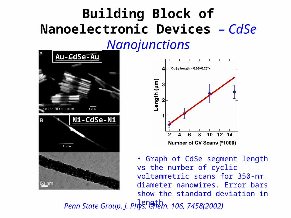
Building Block of Nanoelectronic Devices – CdSe Nanojunctions
Au-CdSe-Au
Ni-CdSe-Ni
Penn State Group. J. Phys. Chem. 106, 7458(2002)
• Graph of CdSe segment length vs the number of cyclic voltammetric scans for 350-nm diameter nanowires. Error bars show the standard deviation in length.
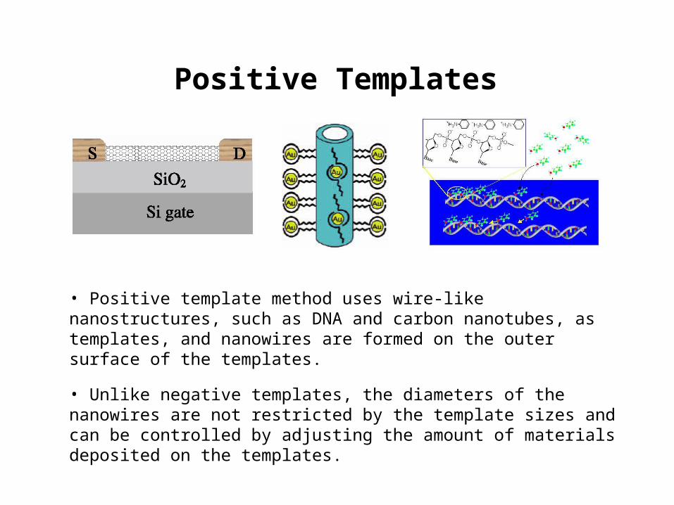
Positive Templates
• Positive template method uses wire-like nanostructures, such as DNA and carbon nanotubes, as templates, and nanowires are formed on the outer surface of the templates.
• Unlike negative templates, the diameters of the nanowires are not restricted by the template sizes and can be controlled by adjusting the amount of materials deposited on the templates.

AuPt
• After Pt or Au deposition on SWNTs, the sample was annealed at 600°C in air for 10 min, which leads to Pt/Au nanoparticles forming chain-like structures.• In contrast to ordinary electroless deposition, no reducing agents are needed for SWNTs.
Carbon Nanotube Template
Dai et al JACS 124(31)9058, 2002.
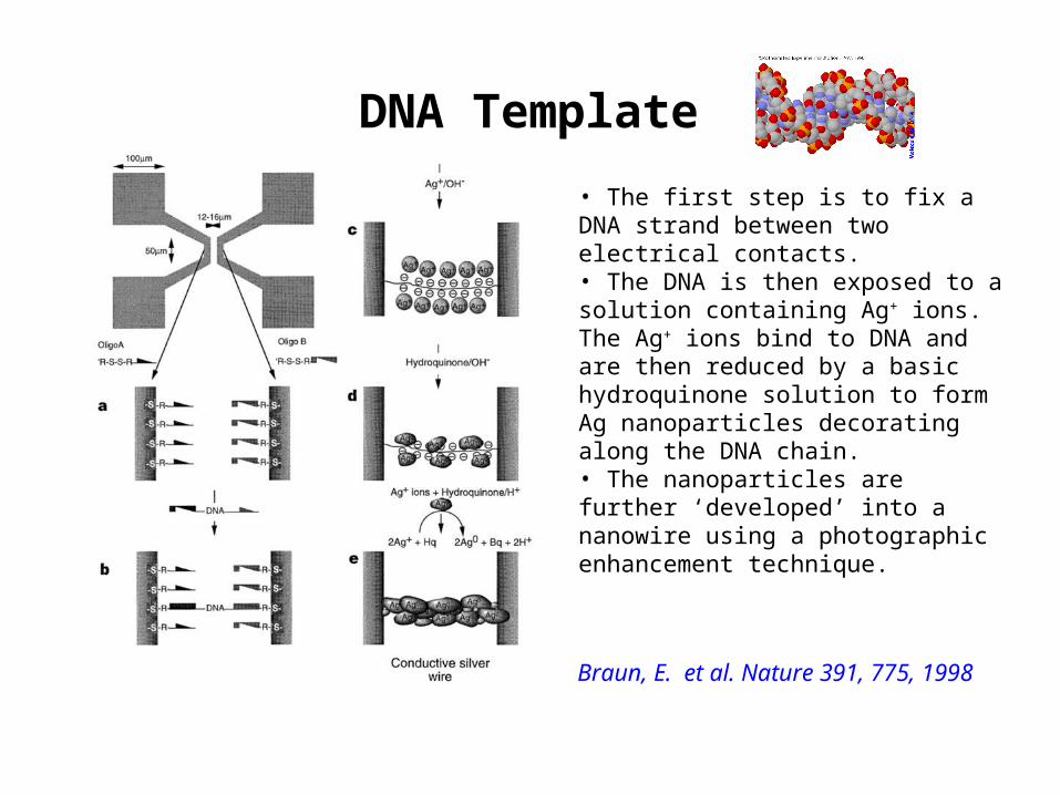
DNA Template
• The first step is to fix a DNA strand between two electrical contacts. • The DNA is then exposed to a solution containing Ag+ ions. The Ag+ ions bind to DNA and are then reduced by a basic hydroquinone solution to form Ag nanoparticles decorating along the DNA chain. • The nanoparticles are further ‘developed’ into a nanowire using a photographic enhancement technique.
Braun, E. et al. Nature 391, 775, 1998

Graphite Step Edge Template
Step 1: Electrodeposit Pd Step 1: Electrodeposit Pd nanowires.nanowires.
Step 2: Transfer the Pd wires to a Step 2: Transfer the Pd wires to a glass slide.glass slide.
Step 3: Apply silver contacts.Step 3: Apply silver contacts.
Step 1
Step 2
Step 3
Penner et al.

Graphite Step Edge Template
Penner et al.

ApplicationsApplications
• Nanoelectronics• Nanomechanics;• Optoelectronics;• Chemical and biosensors;• Catalysis;• Energy related;• - …..

Electrochemistry
NanoelectronicsNanosensors

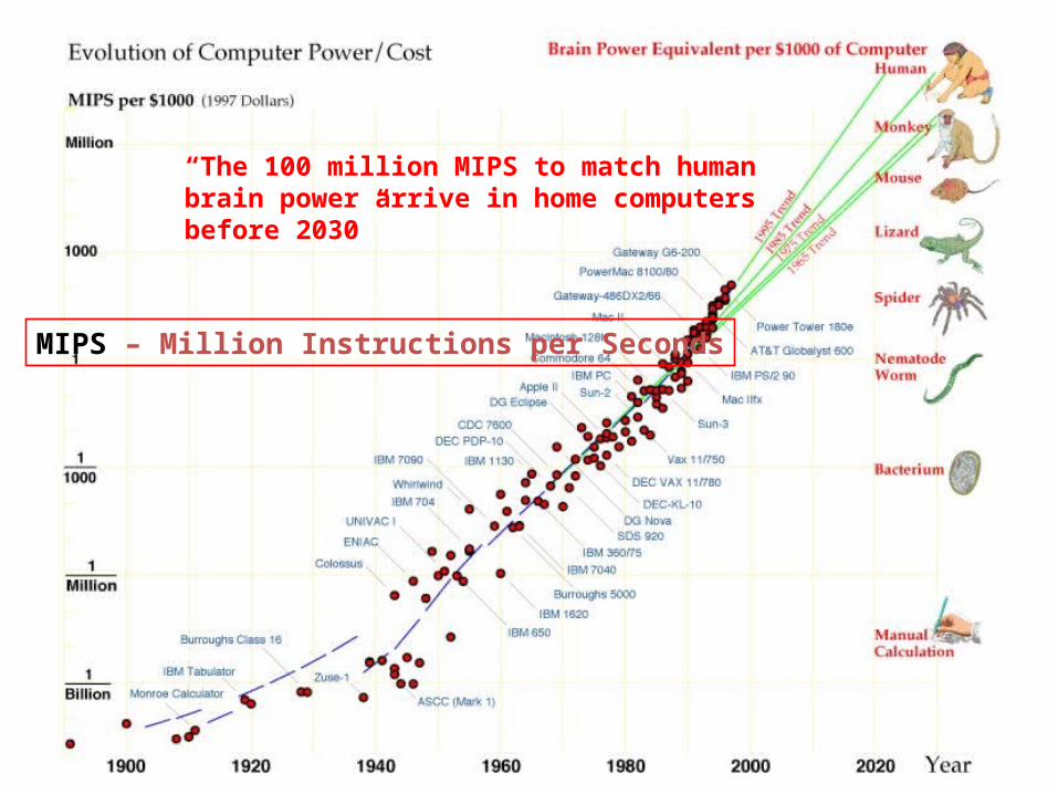
When will computer hardware match the human brain?Hans Moravec
Robotics Institute Carnegie Mellon University
Pittsburgh, PA 15213-3890, USA
“The 100 million MIPS to match human brain power arrive in home computers before 2030”
MIPS – Million Instructions per Seconds
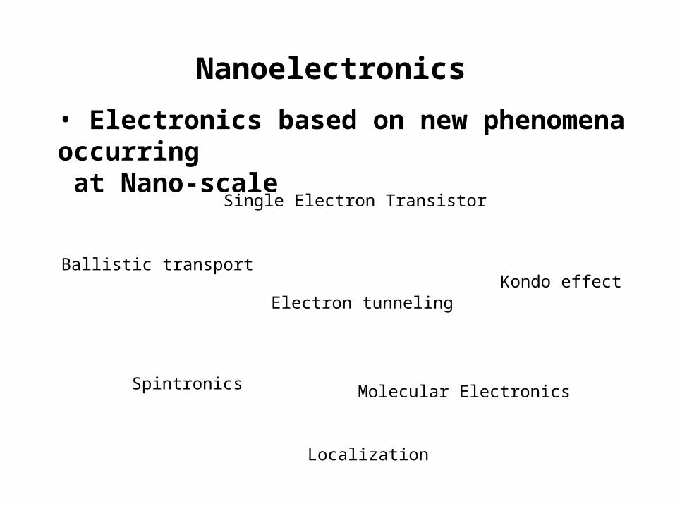
Nanoelectronics
Single Electron Transistor
• Electronics based on new phenomena occurring at Nano-scale
Molecular Electronics
Ballistic transport
Electron tunneling
Spintronics
Kondo effect
Localization

Single Electron Transistor (SET)
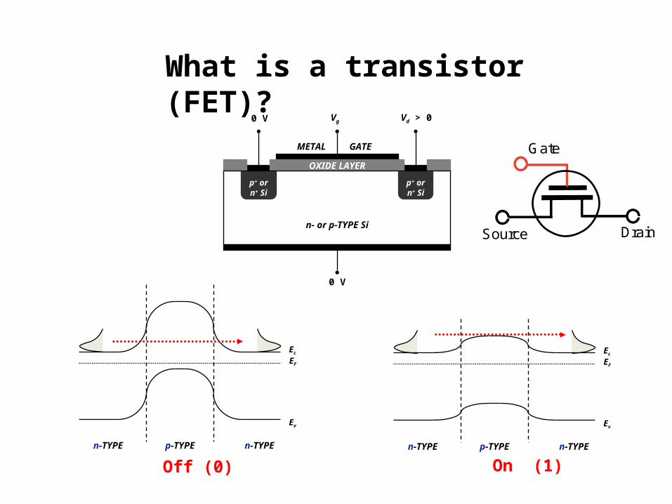
What is a transistor (FET)?
p+ orn+ Si
p+ orn+ Si
OXIDE LAYER
n- or p-TYPE Si
0 V
Vg0 V Vd > 0
GATEMETAL
Ec
EF
Ev
p-TYPE n-TYPEn-TYPE
Off (0)
Ec
EF
Ev
p-TYPE n-TYPEn-TYPE
On (1)
Gate
Source Drain

Single Electron Transistor
;2
2
C
eEeV
• Capacitor charging energy:
C
e
C
QE eQ
22
21
2
dC 02
TkC
eE B
2
2
• To avoid thermal broadening:
T=300 K (room temperature)
FC 1810
(a sphere)
sizeC ~Dot
Gate
Source Drain
EF
e2/C

What is Tunneling?
)(2
2EUm
LeT ~

Single Electron Transistor
Coulomb blockade
Coulomb staircase
• Charge is quantized• Electron Tunneling (R1, R2)
Dot
Gate
Source =

Local Oxidation with a Thin Water Film
STM or AFM tip
Water layer
Ti oxideTi film (3nm)Oxidation
• Substrate Electrode:
nenHMOOnHM n 222
• Tip Electrode:
nOHnHOnHne 222 22
• The thin water film is extremely important in the practical resolution of the fabricated structure. A controlled humidity is recommended.
Snow et al. Science, 270, 1639-41 (1995).
K. Matsumoto, Physica-B 227, 92-4 (1996).
100 nm
5 V
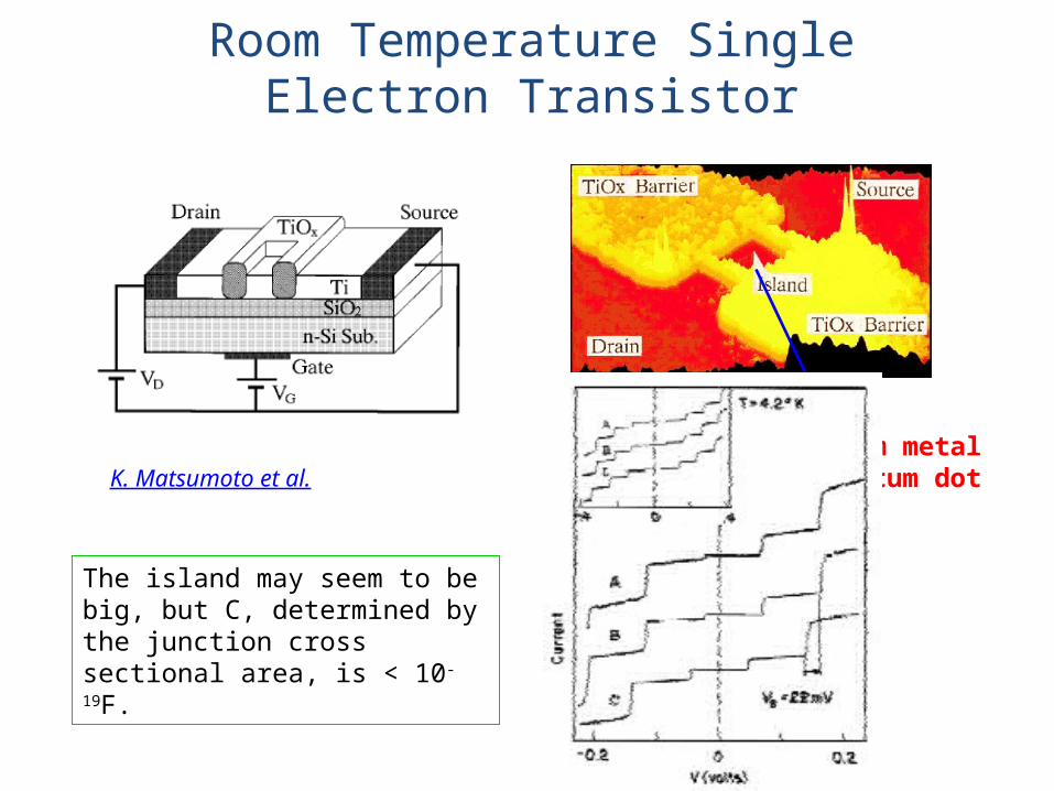
K. Matsumoto et al.~ 30 nm metal quantum dot
The island may seem to be big, but C, determined by the junction cross sectional area, is < 10-19F.
Room Temperature Single Electron Transistor

Shaowei Chen et al. Science 1998, 280, 2098.
Coulomb Blockade in Electrochemistry
Au clusters
C60
Echegoyen et al., 1998

Conductance Quantization

L >> electron mean free pathD>> F, electron wavelength
L
2/ 2D
LR
2~1
DR
G
G changes continuously as D.
D
Conductance
D
G (G
0)
Classical conductance:

L < electron mean free path ballistic transport (no collisions).D~ F, electron wavelength wave nature of electron important.
D=FD=F/2
Motion
Free
Qua
n tiz
ed
N=1
Motion
Free
Qua
n tiz
ed
N=2
01
0 NGTGGN
nn
where, N=0, 1, 2, 3, …and G0 = 2e2/h=77S G
(G0)
D
12
3
4
5 F ~ 1-3 Å
Conductance Quantization
R0=13 k

Quantum Confinement & Standing Waves

Conductance Quantization Metal Nanowires
F ~ 1-3 Å – must be atomically thin! l e ~ nm.
Room temperature.
How to fabricate such wires?How to fabricate such wires?

substrate
RE
CE
Bipo
tentio
stat
Electrolyte
Metal wire
Substrate
insulation
Etching Deposition
tip
+ +
+
++
----
--
- --
+ +
+
++
+++
++
Electrochemical Fabrication
Li & TaoAppl. Phys. Lett.
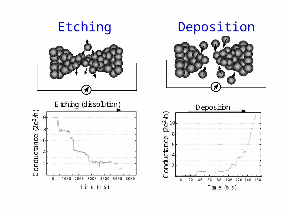
0 1000 2000 3000 4000 5000 6000
Tim e (m s)
Co
ndu
ctan
ce (
2e2
/h)
Etching (dissolution)
2
4
6
8
10
Etching
0 20 40 60 80 100 120 140 160
Tim e (m s)
Co
ndu
ctan
ce (
2e2
/h)
Deposition
2
4
6
8
10
Deposition

From Conductance Quantization to Quantum Tunneling
or
Large gap
DepositionDeposition
EtchingEtching
Li & Tao, Nanotechnology, 10, 221(1999).Morpurgo et al., Appl. Phys. Lett., 13, 2082(1999).

Large gap
EtchingEtching DepositionDeposition
9.5
8.5
7.5
6.5
5.5
4.5
T im e (sec./d iv is ion)
0
1
2
3
-1
-2
Ga
p W
i dth
(A
)
l n (
I/nA
) Tunnelingcurrent
Ln(I) ~ width
Tunneling!
From Conductance Quantization to From Conductance Quantization to Quantum TunnelingQuantum Tunneling
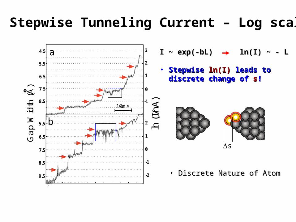
-1
0
1
2
3
-2
-1
0
1
2
Ga
p W
idth
(A
)
7.5
8.5
9.5
8.5
6.5
5.5
7.5
6.5
5.5
4.5
ln (
I/ nA
)
10ms
a
b
I ~ exp(-bL) ln(I) ~ - LI ~ exp(-bL) ln(I) ~ - L
• StepwiseStepwise ln(I) ln(I) leads to leads to discrete change of discrete change of ss!!
Stepwise Tunneling Current – Log scale
s
• Discrete Nature of AtomDiscrete Nature of Atom