
Morphological changes in electrochemically deposited poly ...
Electrochemically promoted carbon-halide
bond cleavage in 4-nitrobenzyl halides Màster Universitari Ciència i tecnologia químiques
Mòdul d’Iniciació a la recerca i treball fi de master
Departament de química
Facultat de Ciències
Zahilia Cabán Huertas
Directors
Iluminada Gallardo
Gonzalo Guirado
September 1, 2011
Memòria presentada per superar el mòdul d’Iniciació a la
recerca i treball fi de màster corresponen al Màster
Universitari Ciència i tecnologia químiques
Zahilia Cabán Huertas
Vist i plau
Iluminada Gallardo Gonzalo Guirado
Bellaterra, September 1, 2011

Acknowledgment First of all, I would like to express my deepest sense of gratitude to my supervisor Dr.
Iluminada Gallardo for the encouragement and excellent advice throughout this study. I am
thankful to Dr. Gonzalo Guirado for his generous assistance and his patient guidance during this
time.
My family is the most amazing thing that I have in my life. They encourage me to be a
better human being. The want the best for my and they do anything to help me to reach my
goals.
Madeline, Lyma and Martin are the best friends that any person can have. I know they
are always be there for me. The internet is the best thing we have, go messenger!!!!!!!! Our
virtual party’s are the best!!!!!
Luis, there is not words to describe how much you help me and much I love you. Thanks
for believe in me and encourage me to have confidence.
Abstract This manuscript reports the study of the carbon-halide bond cleavage in 4-nitrobenzyl
halides, taking special attention to the iodide and fluoride derivatives. The electrochemical
reduction mechanism has been disclosed for both compounds by terms of cyclic voltammetry
and controlled potential electrolysis. In the case of 4-nitrobenzyl iodide, a first one electron
irreversible wave leads to the corresponding 4-nitrobenzyl radical and iodide. However, in the
case of 4-nitrobenzyl fluoride, a first one-electron reversible wave appears at –1.02 vs. SCE
followed by one electron irreversible wave. In this second electron transfer process, the
cleavage of the C-F bond is taking place, so the bond cleavage reaction occurs at the dianion
level. To disclose and understand the electrochemical reduction mechanisms that allows to
obtain important thermodynamic and kinetic data that would help in the understanding of C-X
bond cleavage. This type of bond dissociation reactions are involved in the metabolism
pathways of the human body.
Table of Contents
Introduction ..................................................................................................................... 1!Objectives ................................................................................................................................ 6!
Experimental section ..................................................................................................... 7!Materials ................................................................................................................................... 7!
Solvents ................................................................................................................................. 7!Substrates .............................................................................................................................. 7!Electrolytes ............................................................................................................................ 7!
Synthesis of 4-nitrobenzyl fluoride (3). ................................................................................. 7!Cyclic voltammetry experiments. .......................................................................................... 8!
Working Electrode Calibration ............................................................................................... 9!Controlled potential electrolysis .......................................................................................... 10!Instrumentation ..................................................................................................................... 10!
Cyclic voltammetry and electrolysis ..................................................................................... 10!Gas Chromatography (GC) .................................................................................................. 11!Gas Chromatography-Mass Spectrometry (GC-MS) ........................................................... 11!Nuclear Magnetic Resonance .............................................................................................. 11!
Results and discussion ............................................................................................... 12!Electrochemical behavior of 4-nitrotoluene (1) .................................................................. 12!Electrochemical behavior of 4-nitrobenzyl bromide (2) .................................................... 13!Electrochemical behavior of 4-nitrobenzyl iodide (3) ........................................................ 17!Electrochemical behavior of 4-nitrobenzyl fluoride (4) ..................................................... 22!Thermodynamics ................................................................................................................... 26!
Conclusion .................................................................................................................... 29!
References .................................................................................................................... 30!
Introduction
!"#$%&'$(#)*$+"",-.&')'%#/-$+&0'12(+"*/#-0'1/-$"#+3+4#-*1-521*%&'0#16,"-(+"*/#7- 8-
Introduction Electrochemical processes in which chemical reactions accompany the initial transfer of
one electron is actually a pretty common situation in organic reactions, since the radical or ion
radical species resulting from this initial step are very often chemically unstable. In this reactions
the first electron transfer of the intermediate, so its reduction (or oxidation), is performed at the
electrode. However, the second electron transfer if there is one, which will be usually
energetically more costly than the first, can occur either in the electrode surface or in solution1.
When these two processes take place at successive values of the electrode potential (EE
mechanism, where E means electrochemical step), there is therefore no difficulty of preventing
the occurrence of the second reaction by an appropriate adjustment of the electrode potential.
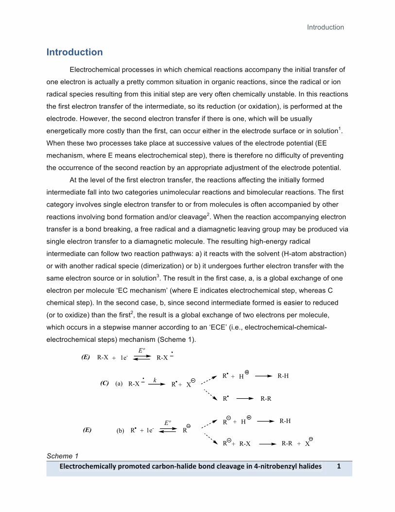
At the level of the first electron transfer, the reactions affecting the initially formed
intermediate fall into two categories unimolecular reactions and bimolecular reactions. The first
category involves single electron transfer to or from molecules is often accompanied by other
reactions involving bond formation and/or cleavage2. When the reaction accompanying electron
transfer is a bond breaking, a free radical and a diamagnetic leaving group may be produced via
single electron transfer to a diamagnetic molecule. The resulting high-energy radical
intermediate can follow two reaction pathways: a) it reacts with the solvent (H-atom abstraction)
or with another radical specie (dimerization) or b) it undergoes further electron transfer with the
same electron source or in solution3. The result in the first case, a, is a global exchange of one
electron per molecule ‘EC mechanism’ (where E indicates electrochemical step, whereas C
chemical step). In the second case, b, since second intermediate formed is easier to reduced
(or to oxidize) than the first2, the result is a global exchange of two electrons per molecule,
which occurs in a stepwise manner according to an ‘ECE’ (i.e., electrochemical-chemical-
electrochemical steps) mechanism (Scheme 1).
+ 1e-
R X+
Eº
k
R-X R-X
R-X
R-RR
+ 1e-Eº
R R
X+R-XR + R-R
R(a)
(b)R
H+ R-H
H+ R-H
(E)
(C)
(E)
Scheme 1

Introduction
9- !"#$%&'$(#)*$+"",-.&')'%#/-$+&0'12(+"*/#-0'1/-$"#+3+4#-*1-521*%&'0#16,"-(+"*/#7-
The second categories (bimolecular reactions), will involve the dimerization reaction of
two anion radicals formed upon a first electron transfer.1 This mechanism is depicted in Scheme
2, involving, as first follow-up reaction, the coupling of two radical anions. According to the
nature of the electron transfer step and the coupled homogenous reaction, which is assumed to
be second order, an EC2 mechanism is operating in this case.
+ 1e-Eº
k
R-X R-X
R-X 2 X+R-R
(E)
(C2) 2 Scheme 2
The way in which coupled homogeneous reactions can be characterized in terms of
mechanism and rate constants by their interference in the electrochemical responses is
disclosed usually by cyclic voltammetry. The products formed in preparative-scale electrolysis
are an important objective not only for investigating the reaction mechanism in cases where
cyclic voltammetry are able to give only a part of it, but also for optimization strategies in the
synthesis of the desired products. After the primary radical has evolved through bond breaking
reaction upon a first reductive electron transfer (at the anion radical level), the determination of
the redox properties of the second radical formed, which is often easier to reduce than the
starting molecule, is a challenging task. Combining mechanistic, thermodynamic and kinetic
information thus gathered on the formation and reduction of these primary (anion radicals) as
well as secondary radicals, allow one to define the conditions under which electrochemistry may
trigger either a radical chemistry or an ionic chemistry.
Organohalogens form a large class of organic compounds, which contain halogen
substituents. Their discovery and application has benefited numerous important fields. For
example: in agriculture, a variety of halogenated pesticides are used to protect crops from
infestation; in disease control, DDT has saved millions of lives by controlling the mosquito vector
of the deadly disease malaria. This compounds are used in the industrial chemical synthesis,
numerous organohalogens serve as important solvents as well as precursors for creating more
complex and biologically active compounds4.
Focusing on unimolecular fragmentation of organic non-aromatic halides Von Stackelberg et al.3
investigated a large number of compounds by polarography and by controlled potential
electrolysis, and were able to formulate the following of useful generalizations.
Introduction
!"#$%&'$(#)*$+"",-.&')'%#/-$+&0'12(+"*/#-0'1/-$"#+3+4#-*1-521*%&'0#16,"-(+"*/#7- :-
1. Allylic benzylic halides are easy to reduce than the corresponding halides; for example
allyl bromide has E0= -1.29 V vs. SCE in 75 % dioxane containing tetraethylammonium
bromide, while under the same conditions n-butyl bromide has E0 = -2.27 V vs. SCE.
2. Vinyl halides are more difficult to reduce than saturated halides (half-wave potentials of -
2.47 and -2.09 V for vinyl and ethyl bromide respectively).
3. Geminal and vicinal polyhalides are easier to reduce than simple halides. For example,
one observes the following orders of decreasing ease of reduction:
CCl4>CHCl3>CH2Cl2>CH3Cl.
4. An increase length of the aliphatic chain attached to a carbon atom decreases the ease
of reduction: methyl bromide > n-butyl bromide >n-octyl bromide. This is probably an
adsorption effect.
5. Half wave potentials are pH independent in R-X compounds. This indicates that the
proton transfer cannot occur either, before or in the transition state reduction.
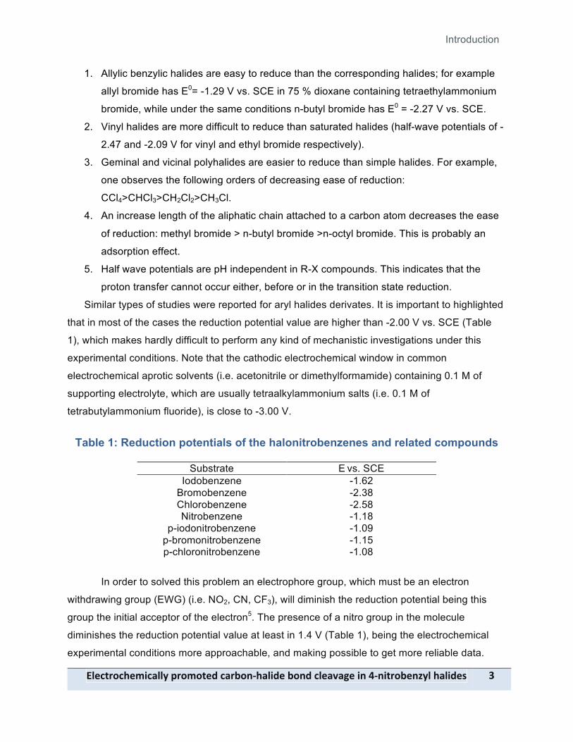
Similar types of studies were reported for aryl halides derivates. It is important to highlighted
that in most of the cases the reduction potential value are higher than -2.00 V vs. SCE (Table
1), which makes hardly difficult to perform any kind of mechanistic investigations under this
experimental conditions. Note that the cathodic electrochemical window in common
electrochemical aprotic solvents (i.e. acetonitrile or dimethylformamide) containing 0.1 M of
supporting electrolyte, which are usually tetraalkylammonium salts (i.e. 0.1 M of
tetrabutylammonium fluoride), is close to -3.00 V.
Table 1: Reduction potentials of the halonitrobenzenes and related compounds
Substrate E vs. SCE Iodobenzene -1.62
Bromobenzene -2.38 Chlorobenzene -2.58 Nitrobenzene -1.18
p-iodonitrobenzene -1.09 p-bromonitrobenzene -1.15 p-chloronitrobenzene -1.08
In order to solved this problem an electrophore group, which must be an electron
withdrawing group (EWG) (i.e. NO2, CN, CF3), will diminish the reduction potential being this
group the initial acceptor of the electron5. The presence of a nitro group in the molecule
diminishes the reduction potential value at least in 1.4 V (Table 1), being the electrochemical
experimental conditions more approachable, and making possible to get more reliable data.

Introduction
5- !"#$%&'$(#)*$+"",-.&')'%#/-$+&0'12(+"*/#-0'1/-$"#+3+4#-*1-521*%&'0#16,"-(+"*/#7-
In the case of those nitroaromatic halides, it has been suggested that reduction of
certain unsaturated and aromatic halides involves an initial addition of the electron to the !
system, followed by cleavage of the sigma bond to halogen. Several authors, including Andrieux et.alt.6, have proposed that cleavage of C-X bonds in halogeno-aromatic radical anions may be
seen as the result of electron transfer from the ! radical anion to the "-arylnucleofugal bond by
an orbital crossing. Therefore the complete process would consist of the addition of an electron
to an electrophore of a complex molecule, followed by intra-molecular electron transfer, and the
subsequent reaction of another part of the molecule. This behavior has been recognized for a
number of years as being characteristic of the halonitrobenzenes, for example, for the 4-
nitrocompounds in acetonitrile7-8.
Cyclic voltammetric experiments have demonstrated that: (a) the nitroaromatic
electrophore is undoubtedly the initial electron acceptor; (b) the carbon-halogen bond cleavage
represented by k1 formally represents a transference of the added electron from the ! system to
the orthogonal sigma system and (c) the decomposition rate k1 depends on X, the order of the
halogen mobility being F < Cl < Br < I.3 It is know from ESR experiments, that there is some
coupling between the two systems9-10, and this coupling presumably provides the mechanism by
which bond cleavage takes place.
The nitro group acts as an intramolecular catalyst for removal of the halogen atom.
Other examples of this behavior have been recognized in the electrochemical reduction of
bromotriphenylethylene11, haloanthracenes12, halobenzophenones13, halobenzonitriles8 and
nitrobenzyl14 (Scheme 3).
X+ 1 e k
X-
O2NProductsX
O2N
Scheme 3
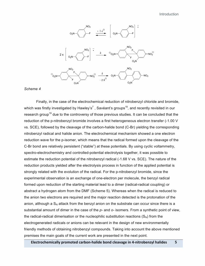
On the other hand, dimerisation of radical anions prior to C – F bond fragmentation has
been postulated in some examples with relatively stable fluorine-substituted radical anions:
fluorobenzonitrile15, pentafluoronitrobenzene16 and 1-Fluoro-2,4-dinitrobenzene17 (Scheme 4).
Introduction
!"#$%&'$(#)*$+"",-.&')'%#/-$+&0'12(+"*/#-0'1/-$"#+3+4#-*1-521*%&'0#16,"-(+"*/#7- ;-
F+ 1 e
k
2 X-
NO2
O2N F
NO2
O2N
F
NO2
O2Nk2 x
NO2
O2N
O2N
NO2
F
NO2
O2NF
O2N
NO2
F
NO2
O2NF
O2N
NO2
Scheme 4
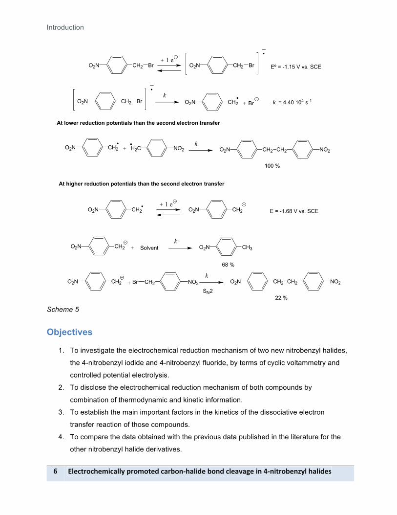
Finally, in the case of the electrochemical reduction of nitrobenzyl chloride and bromide,
which was firstly investigated by Hawley’s7 , Savéant’s groups18, and recently revisited in our
research group19 due to the controversy of those previous studies. It can be concluded that the
reduction of the p-nitrobenzyl bromide involves a first heterogeneous electron transfer (-1.00 V
vs. SCE), followed by the cleavage of the carbon-halide bond (C-Br) yielding the corresponding
nitrobenzyl radical and halide anion. The electrochemical mechanism showed a one electron
reduction wave for the p-isomer, which means that the radical formed upon the cleavage of the
C-Br bond are relatively persistent (“stable”) at these potentials. By using cyclic voltammetry,
spectro-electrochemistry and controlled-potential electrolysis together, it was possible to
estimate the reduction potential of the nitrobenzyl radical (-1.68 V vs. SCE). The nature of the
reduction products yielded after the electrolysis process in function of the applied potential is
strongly related with the evolution of the radical. For the p-nitrobenzyl bromide, since the
experimental observation is an exchange of one-electron per molecule, the benzyl radical
formed upon reduction of the starting material lead to a dimer (radical-radical coupling) or
abstract a hydrogen atom from the DMF (Scheme 5). Whereas when the radical is reduced to
the anion two electrons are required and the major reaction detected is the protonation of the
anion, although a SN attack from the benzyl anion on the substrate can occur since there is a
substantial amount of dimer in the case of the p- and o- isomers. From a synthetic point of view,
the radical-radical dimerisation or the nucleophilic substitution reactions (SN) from the
electrogenerated radicals or anions can be relevant in the design of new environmentally
friendly methods of obtaining nitrobenzyl compounds. Taking into account the above mentioned
premises the main goals of the current work are presented in the next point.
Introduction
<- !"#$%&'$(#)*$+"",-.&')'%#/-$+&0'12(+"*/#-0'1/-$"#+3+4#-*1-521*%&'0#16,"-(+"*/#7-
CH2 Br+ 1 e
kCH2 Br+
O2N CH2 BrO2N
CH2 BrO2N O2N
Eº = -1.15 V vs. SCE
k = 4.40 104 s-1
CH2+ 1 e
O2N CH2O2N E = -1.68 V vs. SCE
At lower reduction potentials than the second electron transfer
CH2 +O2N H2C NO2k
CH2O2N CH2 NO2
100 %
At higher reduction potentials than the second electron transfer
CH2O2N CH2Br+ NO2
kCH2O2N CH2 NO2
22 %SN2
CH2O2N +k
CH3O2N
68 %
Solvent
Scheme 5
Objectives
1. To investigate the electrochemical reduction mechanism of two new nitrobenzyl halides,
the 4-nitrobenzyl iodide and 4-nitrobenzyl fluoride, by terms of cyclic voltammetry and
controlled potential electrolysis.
2. To disclose the electrochemical reduction mechanism of both compounds by
combination of thermodynamic and kinetic information.
3. To establish the main important factors in the kinetics of the dissociative electron
transfer reaction of those compounds.
4. To compare the data obtained with the previous data published in the literature for the
other nitrobenzyl halide derivatives.

Experimental Section
!"#$%&'$(#)*$+"",-.&')'%#/-$+&0'12(+"*/#-0'1/-$"#+3+4#-*1-521*%&'0#16,"-(+"*/#7- =-
Experimental section
Materials
>'"3#1%7-
1. Anhydrous N,N-dimethylformamide (DMF) is stored in an inert atmosphere with molecular sieves.
2. Toluene, SDS > 99.8 % 3. Dicholromethane (DCM), SDS > 99.8 %
>?07%&+%#7-
1. 4-nitrotoluene (1), Aldrich, 99 % 2. 4-nitrobenzyl bromide (2), Aldrich, 99 % 3. 4-nitrobenzyl iodide (4), Aldrich, 99 %
!"#$%&'",%#7-
1. tetra-n-butylammonium tetrafluoroborate (NBu4BF4), Aldrich > 99% 2. tetra-n-methyl ammonium fluoride, Aldrich > 97%
Synthesis of 4-nitrobenzyl fluoride (3).
Tetramethyl ammonium fluoride (0.1583 g, 1.70 mmol) was slowly added under nitrogen
atmosphere to a solution of 4-nitrobenzyl bromide (2) (300mg, 1.38mmol) in 100 mL of
dichloromethane (DCM) at room temperature. The reaction was stirred and monitor through
Thin Layer Chromatography (TLC), after 6 hours, 0.260 g (2.8 mmol) of tetramethyl ammonium
fluoride were added. This step of the reaction has a duration of 6 hours, and then we add tetra-
n-methyl ammonium fluoride (0.2608g, 2.8 mmol). After 48 h, the reactant was fully consumed.
The resulting mixture was extracted with water (3 ! 100 mL). Organic phases dried with MgSO4
and filtered. The solvent was evaporated under reduced pressure and the resulting crude
product was purified using column chromatography through silica (pentane/dichlorometane, 6:4)
to afford 112 mg of the pure product as pale yellow solid.
Experimental Section
@- !"#$%&'$(#)*$+"",-.&')'%#/-$+&0'12(+"*/#-0'1/-$"#+3+4#-*1-521*%&'0#16,"-(+"*/#7-
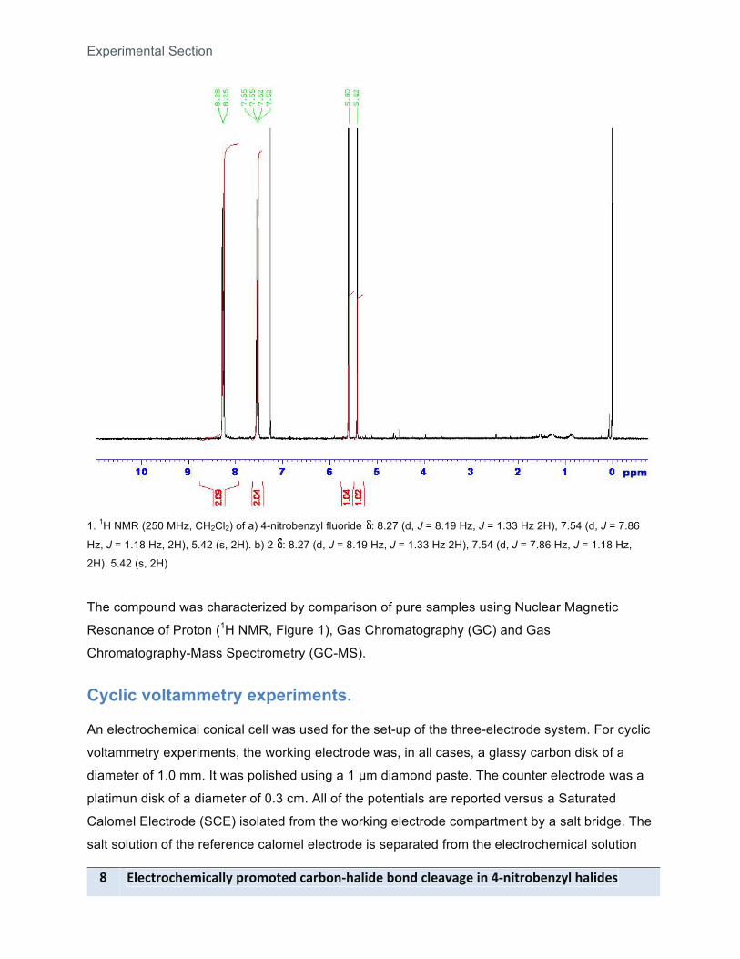
1. 1H NMR (250 MHz, CH2Cl2) of a) 4-nitrobenzyl fluoride : 8.27 (d, J = 8.19 Hz, J = 1.33 Hz 2H), 7.54 (d, J = 7.86
Hz, J = 1.18 Hz, 2H), 5.42 (s, 2H). b) 2 : 8.27 (d, J = 8.19 Hz, J = 1.33 Hz 2H), 7.54 (d, J = 7.86 Hz, J = 1.18 Hz,
2H), 5.42 (s, 2H)
The compound was characterized by comparison of pure samples using Nuclear Magnetic
Resonance of Proton (1H NMR, Figure 1), Gas Chromatography (GC) and Gas
Chromatography-Mass Spectrometry (GC-MS).
Cyclic voltammetry experiments.
An electrochemical conical cell was used for the set-up of the three-electrode system. For cyclic
voltammetry experiments, the working electrode was, in all cases, a glassy carbon disk of a
diameter of 1.0 mm. It was polished using a 1 µm diamond paste. The counter electrode was a
platimun disk of a diameter of 0.3 cm. All of the potentials are reported versus a Saturated
Calomel Electrode (SCE) isolated from the working electrode compartment by a salt bridge. The
salt solution of the reference calomel electrode is separated from the electrochemical solution
Experimental Section
!"#$%&'$(#)*$+"",-.&')'%#/-$+&0'12(+"*/#-0'1/-$"#+3+4#-*1-521*%&'0#16,"-(+"*/#7- A-
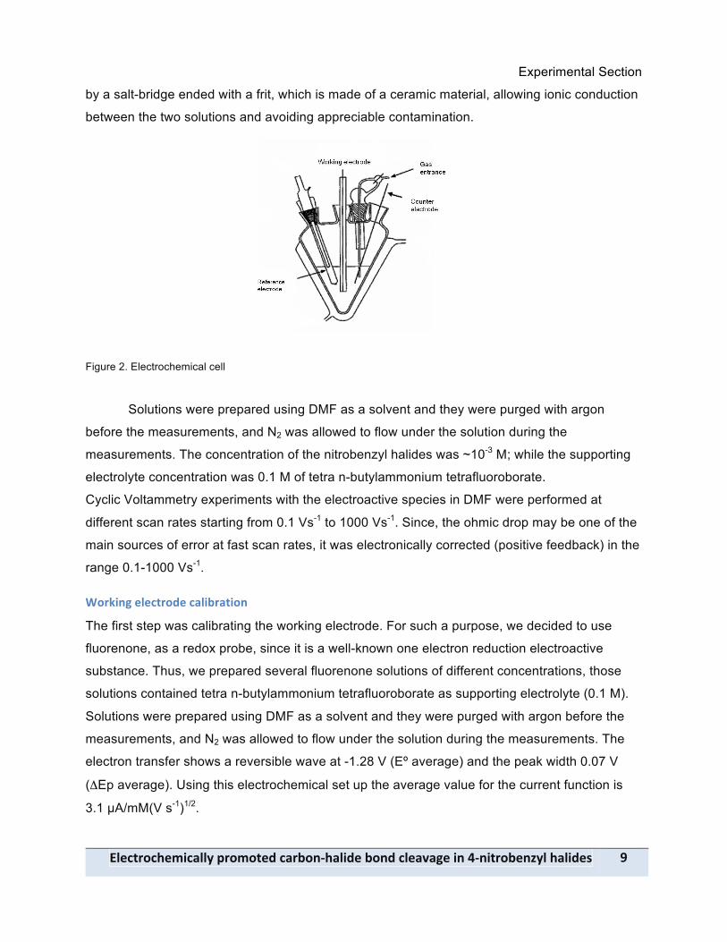
by a salt-bridge ended with a frit, which is made of a ceramic material, allowing ionic conduction
between the two solutions and avoiding appreciable contamination.
Figure 2. Electrochemical cell
Solutions were prepared using DMF as a solvent and they were purged with argon
before the measurements, and N2 was allowed to flow under the solution during the
measurements. The concentration of the nitrobenzyl halides was ~10-3 M; while the supporting
electrolyte concentration was 0.1 M of tetra n-butylammonium tetrafluoroborate.
Cyclic Voltammetry experiments with the electroactive species in DMF were performed at
different scan rates starting from 0.1 Vs-1 to 1000 Vs-1. Since, the ohmic drop may be one of the
main sources of error at fast scan rates, it was electronically corrected (positive feedback) in the
range 0.1-1000 Vs-1.
B'&C*14-#"#$%&'/#-$+"*0&+%*'1-
The first step was calibrating the working electrode. For such a purpose, we decided to use
fluorenone, as a redox probe, since it is a well-known one electron reduction electroactive
substance. Thus, we prepared several fluorenone solutions of different concentrations, those
solutions contained tetra n-butylammonium tetrafluoroborate as supporting electrolyte (0.1 M).
Solutions were prepared using DMF as a solvent and they were purged with argon before the
measurements, and N2 was allowed to flow under the solution during the measurements. The
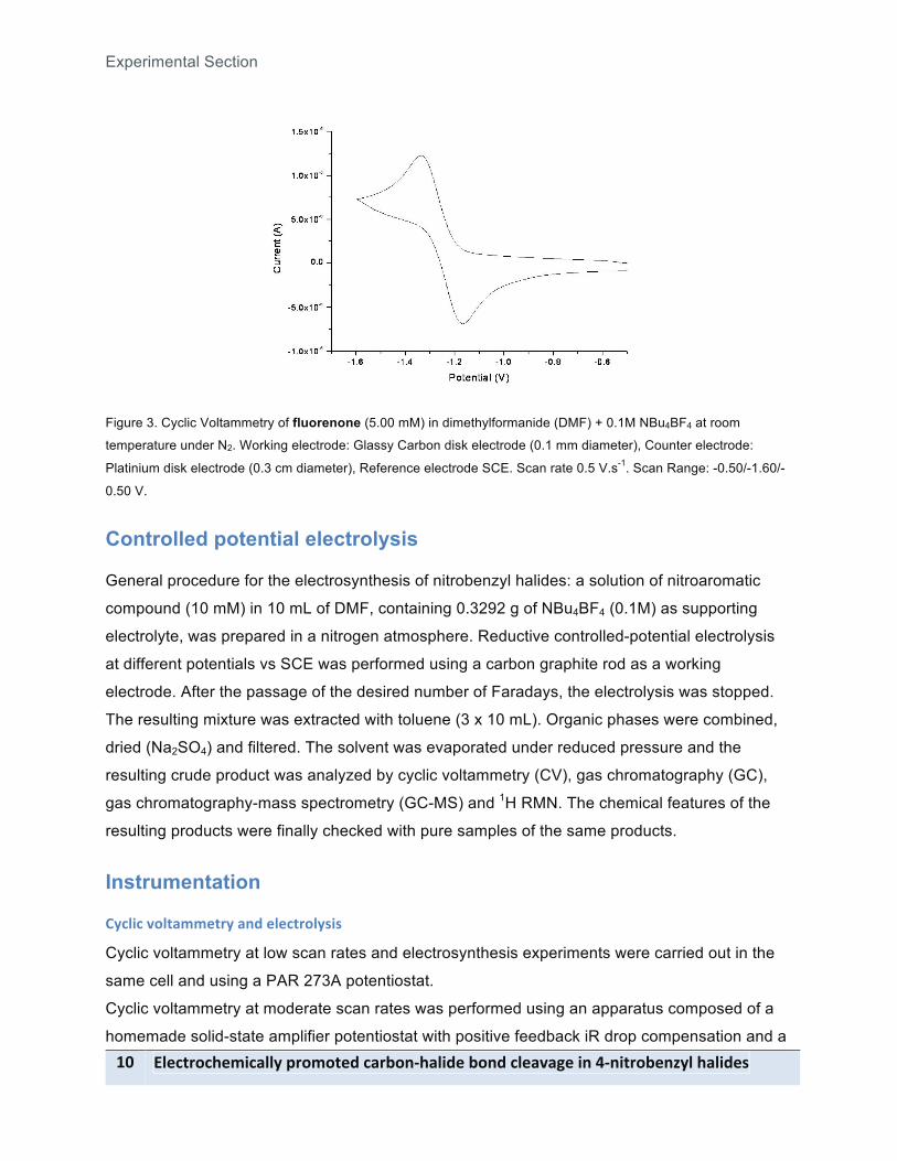
electron transfer shows a reversible wave at -1.28 V (Eº average) and the peak width 0.07 V
(#Ep average). Using this electrochemical set up the average value for the current function is
3.1 µA/mM(V s-1)1/2.
Experimental Section
8D- !"#$%&'$(#)*$+"",-.&')'%#/-$+&0'12(+"*/#-0'1/-$"#+3+4#-*1-521*%&'0#16,"-(+"*/#7-
Figure 3. Cyclic Voltammetry of fluorenone (5.00 mM) in dimethylformanide (DMF) + 0.1M NBu4BF4 at room
temperature under N2. Working electrode: Glassy Carbon disk electrode (0.1 mm diameter), Counter electrode:
Platinium disk electrode (0.3 cm diameter), Reference electrode SCE. Scan rate 0.5 V.s-1. Scan Range: -0.50/-1.60/-
0.50 V.
Controlled potential electrolysis
General procedure for the electrosynthesis of nitrobenzyl halides: a solution of nitroaromatic
compound (10 mM) in 10 mL of DMF, containing 0.3292 g of NBu4BF4 (0.1M) as supporting
electrolyte, was prepared in a nitrogen atmosphere. Reductive controlled-potential electrolysis
at different potentials vs SCE was performed using a carbon graphite rod as a working
electrode. After the passage of the desired number of Faradays, the electrolysis was stopped.
The resulting mixture was extracted with toluene (3 x 10 mL). Organic phases were combined,
dried (Na2SO4) and filtered. The solvent was evaporated under reduced pressure and the
resulting crude product was analyzed by cyclic voltammetry (CV), gas chromatography (GC),
gas chromatography-mass spectrometry (GC-MS) and 1H RMN. The chemical features of the
resulting products were finally checked with pure samples of the same products.
Instrumentation
E,$"*$-3'"%+))#%&,-+1/-#"#$%&'",7*7-
Cyclic voltammetry at low scan rates and electrosynthesis experiments were carried out in the
same cell and using a PAR 273A potentiostat.
Cyclic voltammetry at moderate scan rates was performed using an apparatus composed of a
homemade solid-state amplifier potentiostat with positive feedback iR drop compensation and a
Experimental Section
!"#$%&'$(#)*$+"",-.&')'%#/-$+&0'12(+"*/#-0'1/-$"#+3+4#-*1-521*%&'0#16,"-(+"*/#7- 88-
Tacussel GSTP 4 generator. The voltammograms were displayed on a Tektronix (2212)
instrument.
F+7-E(&')+%'4&+.(,-GFEH-
A PerkinElmer Clarus 500 Gas Chromatograph, which is a fully automated gas chromatograph,
was used for performing a large numbers of routine analyses. All instrument functions are set up
and monitored through either a touch screen or a personal computer.
F+7-E(&')+%'4&+.(,2I+77->.#$%&')#%&,-GFE2I>H-
An Agilent Technologies 7890 A GC system coupled to a mass detector from the Organic
Chemistry Unit of the UAB was used for analyzing the electrolyzed samples and pure
compounds.
J?$"#+&-I+41#%*$-K#7'1+1$#-1H NMR spectra were performed using a Bruker DPX250 (250MHz) instrument available from
the NMR Services of the UAB.
Results and discussion
89- !"#$%&'$(#)*$+"",-.&')'%#/-$+&0'12(+"*/#-0'1/-$"#+3+4#-*1-521*%&'0#16,"-(+"*/#7-
Results and discussion The objective of this section is to disclose the electrochemical reduction mechanism of
4-nitrobenzyl fluoride and iodide. To fulfill this ambitious goal, before to start with
electrochemical studies of the above-mentioned compounds, it is mandatory to broach two
previous points. First, to study the cathodic electrochemical behavior of the 4 nitrotoluene so as
to be familiar with the electrochemical features of nitroaromatic compounds. Second, to revise
the electrochemical result the electrochemical reduction mechanism of 4-nitrobenzyl bromide so
as to learn about the reactivity of the anion radical formed. In both cases, these previous
electrochemical studies will allow not only to know and manage the electrochemical techniques
but also to optimize the chemical strategies that will be used to reach our final goals.
Electrochemical behavior of 4-nitrotoluene (1)
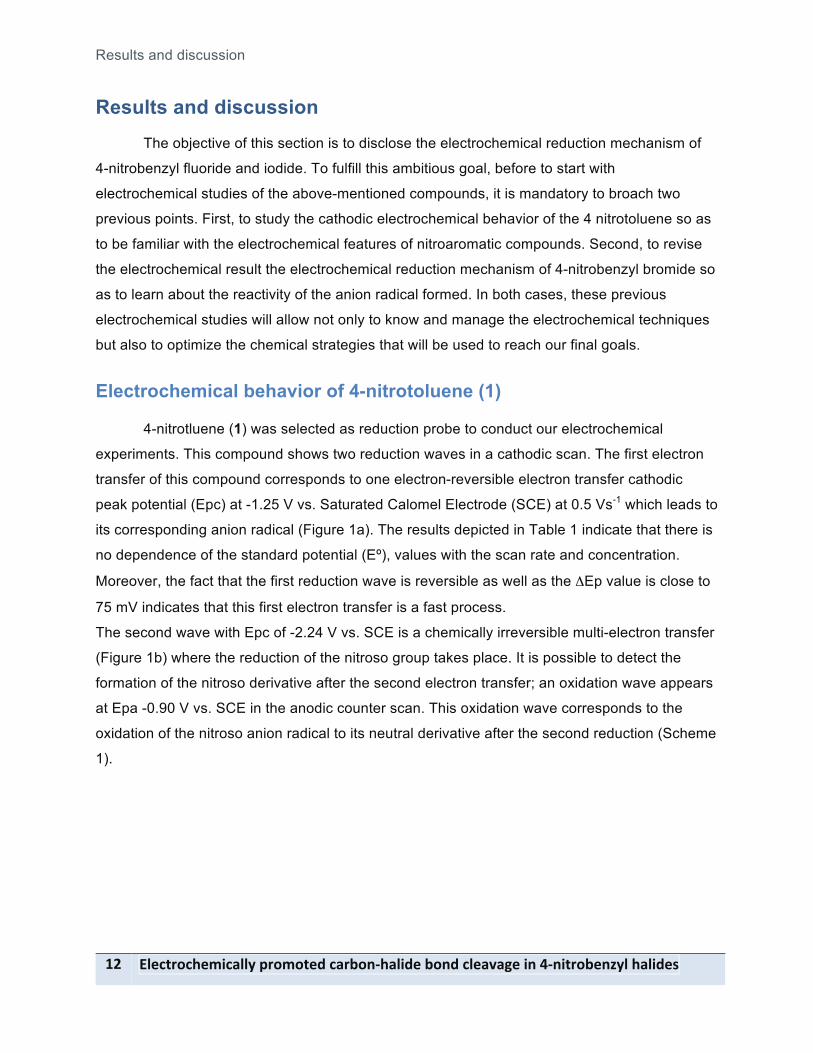
4-nitrotluene (1) was selected as reduction probe to conduct our electrochemical
experiments. This compound shows two reduction waves in a cathodic scan. The first electron
transfer of this compound corresponds to one electron-reversible electron transfer cathodic
peak potential (Epc) at -1.25 V vs. Saturated Calomel Electrode (SCE) at 0.5 Vs-1 which leads to
its corresponding anion radical (Figure 1a). The results depicted in Table 1 indicate that there is
no dependence of the standard potential (Eº), values with the scan rate and concentration.
Moreover, the fact that the first reduction wave is reversible as well as the #Ep value is close to
75 mV indicates that this first electron transfer is a fast process.
The second wave with Epc of -2.24 V vs. SCE is a chemically irreversible multi-electron transfer
(Figure 1b) where the reduction of the nitroso group takes place. It is possible to detect the
formation of the nitroso derivative after the second electron transfer; an oxidation wave appears
at Epa -0.90 V vs. SCE in the anodic counter scan. This oxidation wave corresponds to the
oxidation of the nitroso anion radical to its neutral derivative after the second reduction (Scheme
1).

Results and discussion
!"#$%&'$(#)*$+"",-.&')'%#/-$+&0'12(+"*/#-0'1/-$"#+3+4#-*1-521*%&'0#16,"-(+"*/#7- 8:-
Figure 1. Cyclic Voltammetry of 1 (5.00 mM) in dimethylformanide (DMF) + 0.1M NBu4BF4 at room temperature under
N2. Working electrode: Glassy Carbon disk electrode (0.1 mm diameter), Counter electrode: platinium disk electrode
(0.3 cm diameter), Reference electrode SCE, Scan rate 0.5 V.s-1. a) Scan Range: -0.50/-1.60/-0.50 V vs. SCE b)
Scan Range -0.5/-2.8/-0.5 V vs. SCE
Scheme 1
Table 1. Electrochemical features of the first electron transfer of compound 1
Scan rate (Vs-1) Epc (V) E0 (V) Peak width (V)
Ipc/cv"
(µA/mM(V s-1)1/2)
0.05 -1.21 -1.164 0.06 3.8
0.1 -1.21 -1.159 0.06 3.7
0.3 -1.23 -1.162 0.07 3.5
0.5 -1.25 -1.161 0.08 3.3
0.7 -1.26 -1.163 0.08 3.1
1.0 -1.28 -1.160 0.09 2.9
Average -1.161 0.07 3.4
Standard deviation 0.001 0.01 0.3
Electrochemical behavior of 4-nitrobenzyl bromide (2)
A typical cyclic voltammogram is given in Figure 2a. The cyclic voltammetry behavior of
4-nitrobenzyl bromide (2), at low scan rates in DMF using NBu4BF4 (0.1 M) as supporting
CH2
NO2
H
1
+ 1 e
CH2
NO2
H
E˚=-1.161 V Epc=-2.24 V
CH2
NO
HCH2
NO
H
+ 1 eE˚= -0.99 V
b a
Results and discussion
85- !"#$%&'$(#)*$+"",-.&')'%#/-$+&0'12(+"*/#-0'1/-$"#+3+4#-*1-521*%&'0#16,"-(+"*/#7-
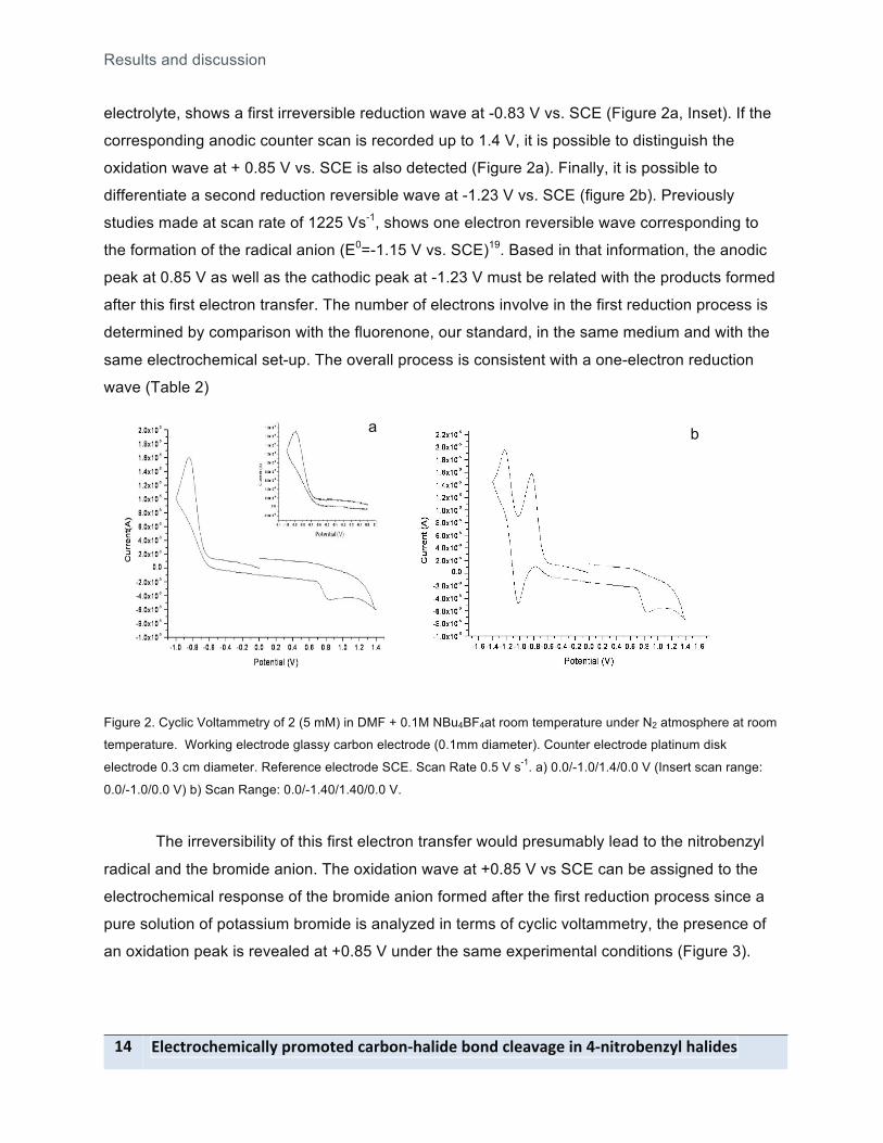
electrolyte, shows a first irreversible reduction wave at -0.83 V vs. SCE (Figure 2a, Inset). If the
corresponding anodic counter scan is recorded up to 1.4 V, it is possible to distinguish the
oxidation wave at + 0.85 V vs. SCE is also detected (Figure 2a). Finally, it is possible to
differentiate a second reduction reversible wave at -1.23 V vs. SCE (figure 2b). Previously
studies made at scan rate of 1225 Vs-1, shows one electron reversible wave corresponding to
the formation of the radical anion (E0=-1.15 V vs. SCE)19. Based in that information, the anodic
peak at 0.85 V as well as the cathodic peak at -1.23 V must be related with the products formed
after this first electron transfer. The number of electrons involve in the first reduction process is
determined by comparison with the fluorenone, our standard, in the same medium and with the
same electrochemical set-up. The overall process is consistent with a one-electron reduction
wave (Table 2)
Figure 2. Cyclic Voltammetry of 2 (5 mM) in DMF + 0.1M NBu4BF4at room temperature under N2 atmosphere at room
temperature. Working electrode glassy carbon electrode (0.1mm diameter). Counter electrode platinum disk
electrode 0.3 cm diameter. Reference electrode SCE. Scan Rate 0.5 V s-1. a) 0.0/-1.0/1.4/0.0 V (Insert scan range:
0.0/-1.0/0.0 V) b) Scan Range: 0.0/-1.40/1.40/0.0 V.
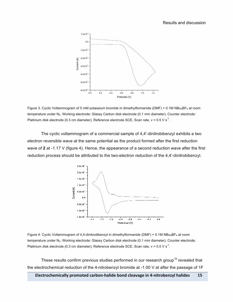
The irreversibility of this first electron transfer would presumably lead to the nitrobenzyl
radical and the bromide anion. The oxidation wave at +0.85 V vs SCE can be assigned to the
electrochemical response of the bromide anion formed after the first reduction process since a
pure solution of potassium bromide is analyzed in terms of cyclic voltammetry, the presence of
an oxidation peak is revealed at +0.85 V under the same experimental conditions (Figure 3).
a b
Results and discussion
!"#$%&'$(#)*$+"",-.&')'%#/-$+&0'12(+"*/#-0'1/-$"#+3+4#-*1-521*%&'0#16,"-(+"*/#7- 8;-
0.0 0.2 0.4 0.6 0.8 1.0 1.2-6.0x10⁻⁵
-5.0x10⁻⁵
-4.0x10⁻⁵
-3.0x10⁻⁵
-2.0x10⁻⁵
-1.0x10⁻⁵
0.0
1.0x10⁻⁵
Cur
rent
(A)
Potential (V)
Figure 3. Cyclic Voltammogram of 5 mM potassium bromide in dimethylformanide (DMF) + 0.1M NBu4BF4 at room
temperature under N2. Working electrode: Glassy Carbon disk electrode (0.1 mm diameter), Counter electrode:
Platinium disk electrode (0.3 cm diameter), Reference electrode SCE, Scan rate, v = 0.5 V s-1.
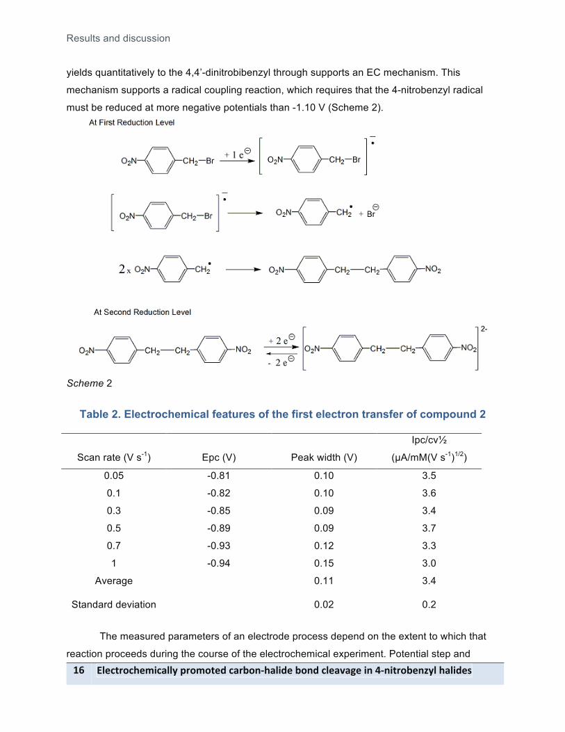
The cyclic voltammogram of a commercial sample of 4,4’-dinitrobibenzyl exhibits a two
electron reversible wave at the same potential as the product formed after the first reduction
wave of 2 at -1.17 V (figure 4). Hence, the appearance of a second reduction wave after the first
reduction process should be attributed to the two-electron reduction of the 4,4’-dinitrobibenzyl.
Figure 4. Cyclic Voltammogram of 4,4-dinitrodibenzyl in dimethylformanide (DMF) + 0.1M NBu4BF4 at room
temperature under N2. Working electrode: Glassy Carbon disk electrode (0.1 mm diameter), Counter electrode:
Platinium disk electrode (0.3 cm diameter), Reference electrode SCE, Scan rate, v = 0.5 V s-1.
These results confirm previous studies performed in our research group19 revealed that
the electrochemical reduction of the 4-nitrobenzyl bromide at -1.00 V at after the passage of 1F
Results and discussion
8<- !"#$%&'$(#)*$+"",-.&')'%#/-$+&0'12(+"*/#-0'1/-$"#+3+4#-*1-521*%&'0#16,"-(+"*/#7-
yields quantitatively to the 4,4’-dinitrobibenzyl through supports an EC mechanism. This
mechanism supports a radical coupling reaction, which requires that the 4-nitrobenzyl radical
must be reduced at more negative potentials than -1.10 V (Scheme 2).
Scheme 2
Table 2. Electrochemical features of the first electron transfer of compound 2
Scan rate (V s-1) Epc (V) Peak width (V)
Ipc/cv"
(µA/mM(V s-1)1/2)
0.05 -0.81 0.10 3.5
0.1 -0.82 0.10 3.6
0.3 -0.85 0.09 3.4
0.5 -0.89 0.09 3.7
0.7 -0.93 0.12 3.3
1 -0.94 0.15 3.0
Average 0.11 3.4
Standard deviation 0.02 0.2
The measured parameters of an electrode process depend on the extent to which that
reaction proceeds during the course of the electrochemical experiment. Potential step and

Results and discussion
!"#$%&'$(#)*$+"",-.&')'%#/-$+&0'12(+"*/#-0'1/-$"#+3+4#-*1-521*%&'0#16,"-(+"*/#7- 8=-
voltammetric methods are applicable to reactions that are fast enough to occur within the
diffusion layer near the electrode surface. The directions and extents of variation of these
provide diagnostic criteria for establishing the type of mechanism involved, and the
measurements themselves provide data for evaluation of the magnitudes of the rate constants
of the coupled reactions.
We proceed to calculate the alpha value for the first electron transfer of the 4-nitrobenzyl
bromide. We calculate the alpha value compare the Epc with the log of the scan rate, the slope
of this plot is . The value we obtained by this method is 0.29, this value
confirm the fact about the slow electron transfer.
The slope for is closed to 0, which indicates that the reaction linked to the electron
transfer is a first order reaction.
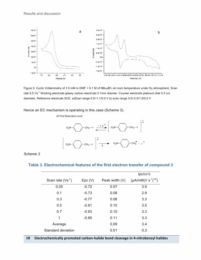
Electrochemical behavior of 4-nitrobenzyl iodide (3)
Similar electrochemical behavior to the above-mentioned for 4-nitrobenzyl bromide is
observed for the other 4-nitrobenzyl iodide. A first one-electron reduction irreversible wave at -
0.93 V vs. SCE (Figure 5a), which presumably will lead to nitrobenzyl radical and iodide. Figure
5b shows that at longer scan range, a second one-electron reversible wave is found at Eº = -
1.17 V as well as two oxidation peaks at 0.65 V and 0.97 V vs. SCE at the corresponding anodic
scan.
The study by cyclic voltammetry at different scan rate permits to establish the
thermodynamics and the kinetic values associate to the first electron transfer for 3 (Table 3).
From those assays it is possible to calculate the order of the reaction linked to the electron
transfer and electron transfer coefficient, which is calculated using the following equation
for this case alpha value is 0.28 that is representative of a slow electron
transfer. Since there is not dependence of the Epc vs. log v, it can be concluded that the
chemical reaction linked to the electron transfer is a first order reaction.
!
"Epc"logv#
$ %
&
' ( =
)0.0296*
!
"Epc"logc#
$ %
&
' (
!
"Epc"logv#
$ %
&
' ( =
)0.0296*
Results and discussion
8@- !"#$%&'$(#)*$+"",-.&')'%#/-$+&0'12(+"*/#-0'1/-$"#+3+4#-*1-521*%&'0#16,"-(+"*/#7-
Figure 5. Cyclic Voltammetry of 3 5 mM in DMF + 0.1 M of NBu4BF4 at room temperature under N2 atmosphere. Scan
rate 0.5 Vs-1 Working electrode glassy carbon electrode 0.1mm diamter. Counter electrode platinum disk 0.3 cm
diameter. Reference electrode SCE. a)Scan range 0.0/-1.1/0.0 V b) scan range 0.0/-2.0/1.5/0.0 V
Hence an EC mechanism is operating in this case (Scheme 3).
Scheme 3
Table 3. Electrochemical features of the first electron transfer of compound 3
Scan rate (Vs-1) Epc (V) Peak width (V)
Ipc/cv"
(µA/mM(V s-1)1/2)
0.05 -0.72 0.07 3.9
0.1 -0.73 0.08 2.9
0.3 -0.77 0.08 3.3
0.5 -0.81 0.10 3.5
0.7 -0.83 0.10 3.3
1 -0.85 0.11 3.3
Average 0.09 3.4
Standard deviation 0.01 0.3
b
a
Results and discussion
!"#$%&'$(#)*$+"",-.&')'%#/-$+&0'12(+"*/#-0'1/-$"#+3+4#-*1-521*%&'0#16,"-(+"*/#7- 8A-
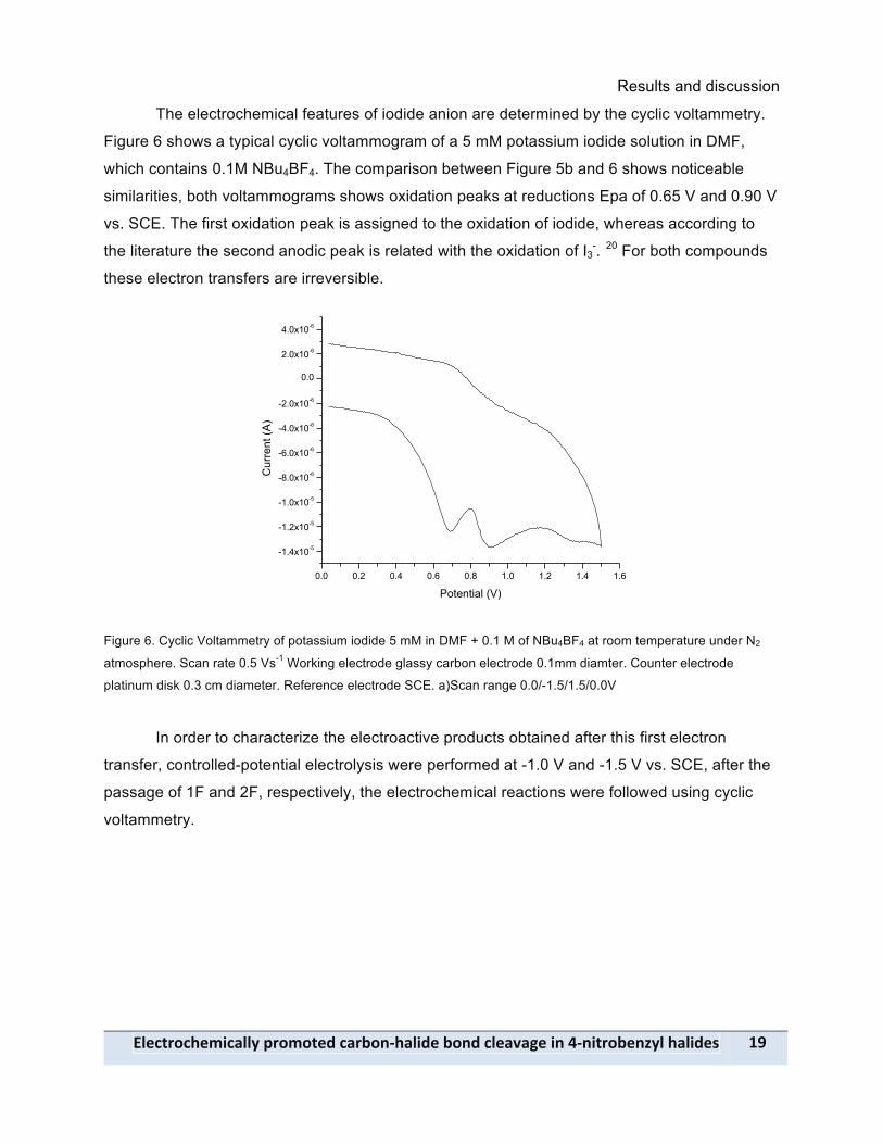
The electrochemical features of iodide anion are determined by the cyclic voltammetry.
Figure 6 shows a typical cyclic voltammogram of a 5 mM potassium iodide solution in DMF,
which contains 0.1M NBu4BF4. The comparison between Figure 5b and 6 shows noticeable
similarities, both voltammograms shows oxidation peaks at reductions Epa of 0.65 V and 0.90 V
vs. SCE. The first oxidation peak is assigned to the oxidation of iodide, whereas according to
the literature the second anodic peak is related with the oxidation of I3-. 20 For both compounds
these electron transfers are irreversible.
0.0 0.2 0.4 0.6 0.8 1.0 1.2 1.4 1.6
-1.4x10⁻⁵
-1.2x10⁻⁵
-1.0x10⁻⁵
-8.0x10⁻⁶
-6.0x10⁻⁶
-4.0x10⁻⁶
-2.0x10⁻⁶
0.0
2.0x10⁻⁶
4.0x10⁻⁶
Cur
rent
(A)
Potential (V)
Figure 6. Cyclic Voltammetry of potassium iodide 5 mM in DMF + 0.1 M of NBu4BF4 at room temperature under N2
atmosphere. Scan rate 0.5 Vs-1 Working electrode glassy carbon electrode 0.1mm diamter. Counter electrode
platinum disk 0.3 cm diameter. Reference electrode SCE. a)Scan range 0.0/-1.5/1.5/0.0V
In order to characterize the electroactive products obtained after this first electron
transfer, controlled-potential electrolysis were performed at -1.0 V and -1.5 V vs. SCE, after the
passage of 1F and 2F, respectively, the electrochemical reactions were followed using cyclic
voltammetry.
Results and discussion
9D- !"#$%&'$(#)*$+"",-.&')'%#/-$+&0'12(+"*/#-0'1/-$"#+3+4#-*1-521*%&'0#16,"-(+"*/#7-
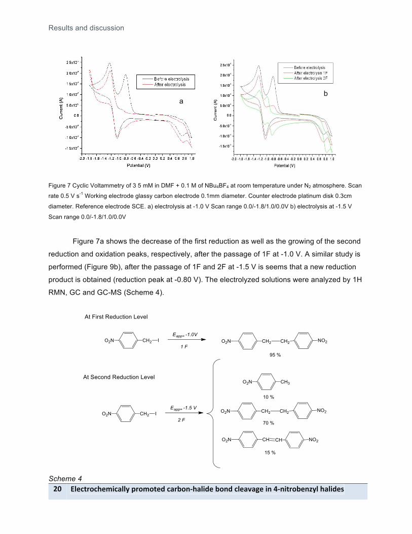
Figure 7 Cyclic Voltammetry of 3 5 mM in DMF + 0.1 M of NBu4BF4 at room temperature under N2 atmosphere. Scan
rate 0.5 V s-1 Working electrode glassy carbon electrode 0.1mm diameter. Counter electrode platinum disk 0.3cm
diameter. Reference electrode SCE. a) electrolysis at -1.0 V Scan range 0.0/-1.8/1.0/0.0V b) electrolysis at -1.5 V
Scan range 0.0/-1.8/1.0/0.0V
Figure 7a shows the decrease of the first reduction as well as the growing of the second
reduction and oxidation peaks, respectively, after the passage of 1F at -1.0 V. A similar study is
performed (Figure 9b), after the passage of 1F and 2F at -1.5 V is seems that a new reduction
product is obtained (reduction peak at -0.80 V). The electrolyzed solutions were analyzed by 1H
RMN, GC and GC-MS (Scheme 4).
Scheme 4
a b
Results and discussion
!"#$%&'$(#)*$+"",-.&')'%#/-$+&0'12(+"*/#-0'1/-$"#+3+4#-*1-521*%&'0#16,"-(+"*/#7- 98-
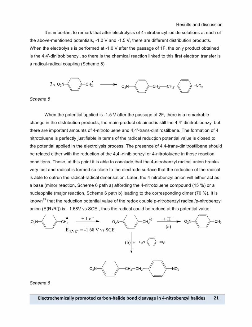
It is important to remark that after electrolysis of 4-nitrobenzyl iodide solutions at each of
the above-mentioned potentials, -1.0 V and -1.5 V, there are different distribution products.
When the electrolysis is performed at -1.0 V after the passage of 1F, the only product obtained
is the 4,4’-dinitrobibenzyl, so there is the chemical reaction linked to this first electron transfer is
a radical-radical coupling (Scheme 5)
Scheme 5
When the potential applied is -1.5 V after the passage of 2F, there is a remarkable
change in the distribution products, the main product obtained is still the 4,4’-dinitrobibenzyl but
there are important amounts of 4-nitrotoluene and 4,4’-trans-dintirostilbene. The formation of 4
nitrotoluene is perfectly justifiable in terms of the radical reduction potential value is closed to
the potential applied in the electrolysis process. The presence of 4,4-trans-dinitrostilbene should
be related either with the reduction of the 4,4’-dinibibenzyl or 4-nitrotoluene in those reaction
conditions. Those, at this point it is able to conclude that the 4-nitrobenzyl radical anion breaks
very fast and radical is formed so close to the electrode surface that the reduction of the radical
is able to outrun the radical-radical dimerisation. Later, the 4 nitrobenzyl anion will either act as
a base (minor reaction, Scheme 6 path a) affording the 4-nitrotoluene compound (15 %) or a
nucleophile (major reaction, Scheme 6 path b) leading to the corresponding dimer (70 %). It is
known19 that the reduction potential value of the redox couple p-nitrobenzyl radical/p-nitrobenzyl
anion (E(R./R-)) is - 1.68V vs SCE , thus the radical could be reduce at this potential value.
Scheme 6
CH2O2N CH3O2N+ H ++ 1 e -
E = -1.68 V vs SCE
CH2O2N
(R / R )
+
(a)
(b)
O2N
CH2IO2N
CH2 CH2 NO2

Results and discussion
99- !"#$%&'$(#)*$+"",-.&')'%#/-$+&0'12(+"*/#-0'1/-$"#+3+4#-*1-521*%&'0#16,"-(+"*/#7-
Electrochemical behavior of 4-nitrobenzyl fluoride (4)
The 4-nitrobenzyl fluoride (4) has also been investigated by means of cyclic voltammetry
in DMF + 0.1 M Bu4NBF4. Figure 8a shows the typical cyclic voltammogram of this compound at
low scan rate. The first wave corresponds to the reversible reduction of the substrate and the
standard potential of this compound is summarized in Table 5. Hence, 4 take reversibly a first
electron, which is mainly located on the nitro group according to the value of the standard
potential (about –1.016 V vs. SCE) to form an anion radical (Scheme 7)
CH2 F+ 1 e
O2N
- 1 e
CH2 FO2N
Scheme 7
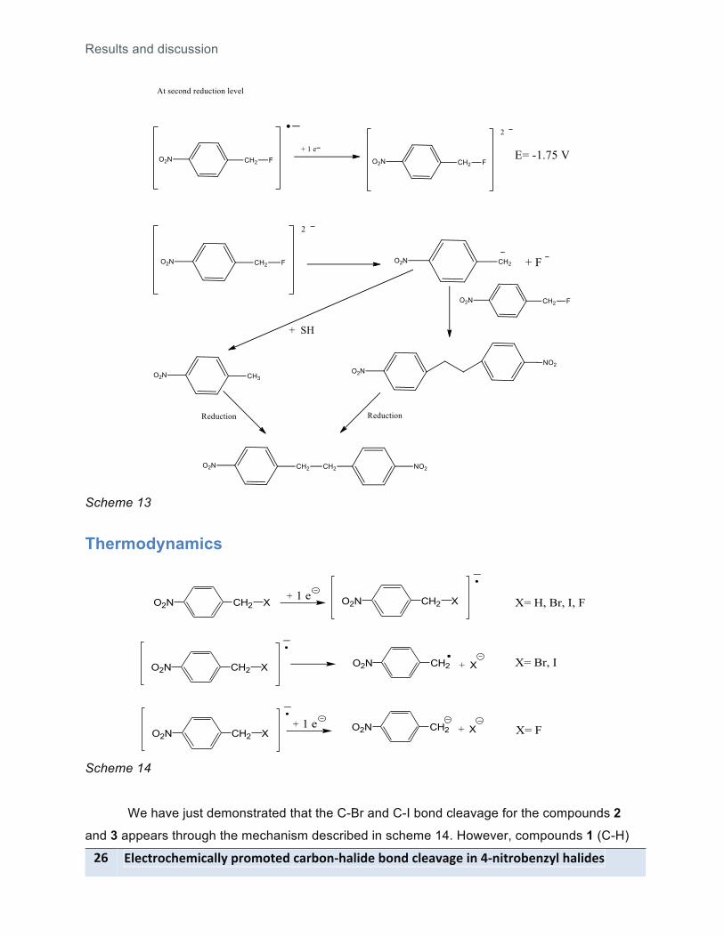
A second irreversible one electron reduction wave and a third irreversible multielectronic
wave appear at -1.80 V, whereas an oxidation wave corresponding to the nitroso derivatives
appears at -2.40 V (Figure 8b). Focusing on the first two reduction waves, since the obtention of
nitroso derivates is not the main interest in this study, it fairly to think that the anion radical takes
a second electron and the dianion would react, it may break at the level of carbon-fluorine bond
(Scheme 8).
+ 1 e CH2 FO2N +CH2 FO2N
Scheme 8
Figure 8. Cyclic Voltammetry of 4 (5 mM) in DMF + 0.1M NBu4BF4 at room temperature under N2 atmosphere.
Working electrode glassy carbon electrode (0.1mm diamter). Counter electrode platinum disk electrode 10.3 cm
a b
Results and discussion
!"#$%&'$(#)*$+"",-.&')'%#/-$+&0'12(+"*/#-0'1/-$"#+3+4#-*1-521*%&'0#16,"-(+"*/#7- 9:-
diameter. Reference electrode SCE. Scan Rate 0.5 V s-1. a) scan Range: 0.0/-1.40/0.0 V,b) Scan Range: 0.0/-
2.80/0.0 V.
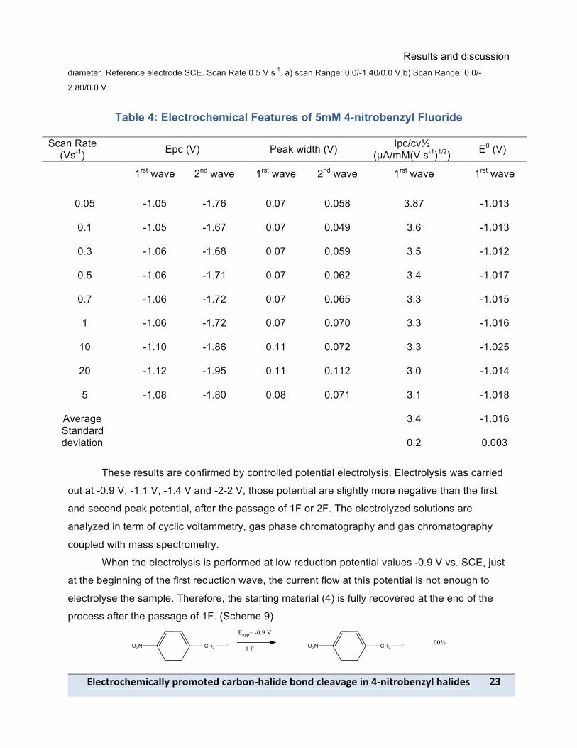
Table 4: Electrochemical Features of 5mM 4-nitrobenzyl Fluoride
Scan Rate (Vs-1) Epc (V) Peak width (V) Ipc/cv"
(µA/mM(V s-1)1/2) E0 (V)
1rst wave 2nd wave 1rst wave 2nd wave 1rst wave 1rst wave
0.05 -1.05 -1.76 0.07 0.058 3.87 -1.013
0.1 -1.05 -1.67 0.07 0.049 3.6 -1.013
0.3 -1.06 -1.68 0.07 0.059 3.5 -1.012
0.5 -1.06 -1.71 0.07 0.062 3.4 -1.017
0.7 -1.06 -1.72 0.07 0.065 3.3 -1.015
1 -1.06 -1.72 0.07 0.070 3.3 -1.016
10 -1.10 -1.86 0.11 0.072 3.3 -1.025
20 -1.12 -1.95 0.11 0.112 3.0 -1.014
5 -1.08 -1.80 0.08 0.071 3.1 -1.018
Average 3.4 -1.016 Standard deviation
0.2 0.003
These results are confirmed by controlled potential electrolysis. Electrolysis was carried
out at -0.9 V, -1.1 V, -1.4 V and -2-2 V, those potential are slightly more negative than the first
and second peak potential, after the passage of 1F or 2F. The electrolyzed solutions are
analyzed in term of cyclic voltammetry, gas phase chromatography and gas chromatography
coupled with mass spectrometry.
When the electrolysis is performed at low reduction potential values -0.9 V vs. SCE, just
at the beginning of the first reduction wave, the current flow at this potential is not enough to
electrolyse the sample. Therefore, the starting material (4) is fully recovered at the end of the
process after the passage of 1F. (Scheme 9)

Results and discussion
95- !"#$%&'$(#)*$+"",-.&')'%#/-$+&0'12(+"*/#-0'1/-$"#+3+4#-*1-521*%&'0#16,"-(+"*/#7-
Scheme 9
Surprisingly, when the potential applied is -1.1 V or -1.4 V before the second reduction
wave, the monitor of the reaction (Figure 9a) as well as the analysis of the products at the end
of the electrolysis, after the passage of 1F reveals the formation of 4,4’-dinitrobibenzyl and 4,4’-
cis-dinitrostilbene (Scheme 10). The amount of 4,4’-cis-dinistrostilbene is higher when the
potential value goes from -1.1 V to -1.4 V. These results seem to indicate that there is either a
slow chemical reaction linked to the electron transfer (scheme 11 path a), or a radical anion
dimerization reaction (Scheme 11 path b)
Moreover, the yield of 4,4’-cis-dinitrostilbene, which has not been obtained in the
electrochemical reduction of either the bromine or iodide derivates after the first reduction wave,
indicates that the fluorine anion would react with the 4,4’-dinitrobibenzyl leading to the
corresponding stilbene derivate.
-1.4 -1.2 -1.0 -0.8 -0.6 -0.4 -0.2 0.0-1.0x10⁻⁵
-5.0x10⁻⁶
0.0
5.0x10⁻⁶
1.0x10⁻⁵
1.5x10⁻⁵
Cur
rent
(A)
Potential (V)
Before electrolysis After electrolysis
-1.4 -1.2 -1.0 -0.8 -0.6 -0.4 -0.2 0.0-1.0x10⁻⁵
-5.0x10⁻⁶
0.0
5.0x10⁻⁶
1.0x10⁻⁵
1.5x10⁻⁵
Cur
rent
(A)
Potential (V)
Before electrolysis After electrolysis
Figure 9 Cyclic Voltammetry of 4 (5 mM) in DMF + 0.1M NBu4BF4 at room temperature under N2 atmosphere.
Working electrode glassy carbon electrode (0.1mm diamter). Counter electrode platinum disk electrode 0.3 cm
diameter. Reference electrode SCE. Scan Rate 0.5 V s-1. a) electrolysis at -1.4 V scan range: 0.0/-1.40/0.0 V,b)
electrolysis at -2.2 V scan range: 0.0/-1.40/0.0 V.
Scheme 10
a b

Results and discussion
!"#$%&'$(#)*$+"",-.&')'%#/-$+&0'12(+"*/#-0'1/-$"#+3+4#-*1-521*%&'0#16,"-(+"*/#7- 9;-
Scheme 11
When, electrolysis is performed until 2F at a potential slightly more negative than the
second peak potential, -2.2 V, similar products are obtained (Figure 9b). However, a closer look
to the nature of the reaction products reveals important mechanistic differences (Scheme 12).
The formation of 4-nitrotoluene should be related to the formation of the 4-nitrobenzyl anion.
This means that the 4-nitrobenzyl fluoride dianion has a faster cleavage that the corresponding
anion radical. This dianion can either react with a molecule of 4 following a SN2 reaction leading
to 4,4’-dinitrobibenzyl or being protonated in the reaction media yielding the 4-nitrotoluene (1).
Since, both products are electroactive at this potential the formation of the 4,4’-trans-
dinitrostilbene could be related to the reduction of 4-nitrotoluene or 4,4’-dintitrobibenzyl
(Scheme 13).
Scheme 12
O2N CH2 F
O2N CH3
O2N CH2 CH2 NO2
O2N
16%
56%
NO2 27%
-2.2 V
2 F
Results and discussion
9<- !"#$%&'$(#)*$+"",-.&')'%#/-$+&0'12(+"*/#-0'1/-$"#+3+4#-*1-521*%&'0#16,"-(+"*/#7-
Scheme 13
Thermodynamics
CH2 X+ 1 e
CH2 XO2N +
O2N CH2 XO2N
CH2 XO2N
X= H, Br, I, F
X= Br, I
+ 1 eCH2 XO2N X= FCH2 XO2N +
Scheme 14
We have just demonstrated that the C-Br and C-I bond cleavage for the compounds 2
and 3 appears through the mechanism described in scheme 14. However, compounds 1 (C-H)
Results and discussion
!"#$%&'$(#)*$+"",-.&')'%#/-$+&0'12(+"*/#-0'1/-$"#+3+4#-*1-521*%&'0#16,"-(+"*/#7- 9=-
and 4 (C-F) do not undergo through dissociative electron transfer reaction at the first electron
transfer level and in the cyclic voltammetry time scale. However, compound 4 shows a C-F
bond cleavage at the second electron transfer level.
The observed reactivity can be related to the ability of the aromatic radical anions to
undergo cleavage of the carbon halogen bond. The order H<F<Cl<Br<I is the same as reported
in the literature for other nitro and cyano derivatives with the peculiarity that in our case there is
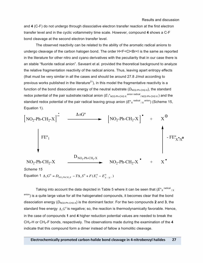
an stable “fluoride radical anion”. Saveant et al. provided the theoretical background to analyze
the relative fragmentation reactivity of the radical anions. Thus, leaving apart entropy effects
(that must be very similar in all the cases and should be around 27.8 J/mol according to
previous works published in the literature21), in this model the fragmentative reactivity is a
function of the bond dissociation energy of the neutral substrate (DNO2-Ph-CH2-X), the standard
redox potential of the pair substrate:radical anion (E1°NO2-Ph-CH2-X anion radical
/ NO2-Ph-CH2-X ) and the
standard redox potential of the pair radical leaving group anion (E°X radical
/ X anion) (Scheme 15,
Equation 1).
Scheme 15
Equation 1
!
" rG0 = DNO2PhCH2X
#T" rS0 + F(E1
0 # EX . /X #0 )
Taking into account the data depicted in Table 5 where it can be seen that (E°X radical
/ X
anion) is a quite large value for all the halogenated compounds, it becomes clear that the bond
dissociation energy (DNO2-Ph-CH2-X) is the dominant factor. For the two compounds 2 and 3, the
standard free energy 0Gr! is negative; so, the reaction is thermodynamically favorable. Hence,
in the case of compounds 1 and 4 higher reduction potential values are needed to break the
CH2-H or CH2-F bonds, respectively. The observations made during the examination of the 4
indicate that this compound form a dimer instead of fallow a homolitic cleavage.
!NO2-Ph-CH2-X NO2-Ph-CH2-X + X
NO2-Ph-CH2-X NO2-Ph-CH2-X + X
! rGº
NO2-Ph-CH2-XD
FEº1 - FEºX /X
Results and discussion
9@- !"#$%&'$(#)*$+"",-.&')'%#/-$+&0'12(+"*/#-0'1/-$"#+3+4#-*1-521*%&'0#16,"-(+"*/#7-
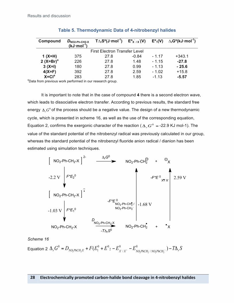
Table 5. Thermodynamic Data of 4-nitrobenzyl halides
Compound DNO2-Ph-CH2-X (kJ!mol-1)
T"rSº(J!mol-1) EºX! / X
-(V) Eº1(V) "rGº(kJ!mol-1)
First Electron Transfer Level 1 (X=H) 375 27.8 -0.84 - 1.17 +343.1
2 (X=Br)a 226 27.8 1.48 - 1.15 -27.8 3 (X=I) 180 27.8 0.99 - 1.13 - 25.6 4(X=F) 392 27.8 2.59 - 1.02 +15.8 X=Cla 283 27.8 1.85 -1.13 -5.57
aData from previous work performed in our research group.
It is important to note that in the case of compound 4 there is a second electron wave,
which leads to dissociative electron transfer. According to previous results, the standard free
energy 0Gr! of the process should be a negative value. The design of a new thermodynamic
cycle, which is presented in scheme 16, as well as the use of the corresponding equation,
Equation 2, confirms the exergonic character of the reaction ( =! 0Gr -22.9 KJ mol-1). The
value of the standard potential of the nitrobenzyl radical was previously calculated in our group,
whereas the standard potential of the nitrobenzyl fluoride anion radical / dianion has been
estimated using simulation techniques.
Scheme 16
Equation 2 STEEEEFDG rPhCHNOPhCHNOXXXPhCHNOr !"""++=! "" )( 0/
0/2
001
0
22.22
.22
NO2-Ph-CH2-X2-
NO2-Ph-CH2-X
NO2-Ph-CH2-X
F*E20
F*E10
!rG0
NO2-Ph-CH2-XD
NO2-Ph-CH2 X+
NO2-Ph-CH2 X+
-F*E 0X / X-
-F*E 0NO2-Ph-CH2 /NO2-Ph-CH2
-
-T!rS0
-1.68 V
2.59 V-2.2 V
-1.03 V
Conclusion
!"#$%&'$(#)*$+"",-.&')'%#/-$+&0'12(+"*/#-0'1/-$"#+3+4#-*1-521*%&'0#16,"-(+"*/#7- 9A-
Conclusion The electrochemical reduction mechanism of the 4-nitrobenzyl iodide (3) and 4-
nitrobenzyl fluoride (4) in polar aprotic solvents has been disclosed using cyclic voltammetry
and controlled potential electrolysis.
The electrochemical studies based on the reduction of 4-nitrobenzyl iodide (3) reveals a
one electron irreversible reduction, which means that the radical anion formed upon reduction is
not stable at cyclic voltammetry time scale. The use altogether of cyclic voltammetry and
controlled potential electrolysis experiments allows to establish that the chemical reaction linked
to the electron transfer is the rupture of the C-I benzylic bond. After that the 4-nitrobenzyl radical
anions is able to outrun the radical-radical dimerization.
On the other hand, 4-nitrobenzyl fluoride (4) shows a different behavior respect to the 3.
Compound 4 undergoes one electron reversible electron transfer (Eº=-1.02 vs. SCE), which
means that the radical anion is stable at cyclic voltammetry time scale. This first electron
transfer is followed by a second electron transfer at Epc=-1.71 vs. SCE at 0.5 V s-1. Since the
reduction wave is irreversible, it is possible to conclude that there is a chemical reaction linked
to the electron transfer. The use of cyclic voltammetry and controlled potential electrolysis
permits to establish that the C-F bond cleavage is the chemical reaction coupled to this second
electron transfer.
The calculation of #rG0 for the bond breaking reaction of C-I and C-F supports the fact
that the cleavage of the C-I bond is occurring at the first electron transfer, whereas the rupture
of the C-F is taking place at the dianion level.
Finally, it has been experimentally observed that the electrolysis of 4 after the first
electron transfer, leads to dimeric compounds. The fact that the reaction is endergonic indicates
that the C-F bond rupture after the first electron transfer is an unfavorable reaction. Thus, the
formation of the dimeric should follow an spontaneous reaction, which can be a dimerisation
reaction of to radical anions followed by a loss of two fluoride anions (Scheme 11, path b)
From a synthetic point of view, the radical-radical dimerisation or anion radical
dimerisation from the electrogenerated radicals or anion radicals can be relevant for the design
of new environmentally friendly methods for obtaining nitroaromatic dimeric compounds.

References
:D- !"#$%&'$(#)*$+"",-.&')'%#/-$+&0'12(+"*/#-0'1/-$"#+3+4#-*1-521*%&'0#16,"-(+"*/#7-
References (1) Pletcher, D. Organic Electrochemistry: An Introduction and a Guide; 3rd edition ed. New York, 1971. (2) Bard, A. J.; Faulkner, L. R. Electrochemical Methods Fundamentals and Applications; 2nd edition ed.; JOHN WILEY & SONS, INC., 2001. (3) Fry, A. J. Synthetic Organic Chemistry; Harper & Row: Newe York, 1972. (4) Chan, W. Y.; Yakunin, A.; Edwards, E. A.; Pai, E. F. Breaking Carbon-Fluorine Bonds – CrystalStructure of Defluorinase, 2008. (5) Andrieux, C. P.; Farriol, M.; Gallardo, I.; Marquet, J. Journal of the Chemical Society, Perkin Transactions 2 2002, 985. (6) Andrieux, C. P.; Savéant, J.-M.; Tallec, A.; Tardivel, R.; Tardy, C. Journal of the American Chemical Society 1996, 118, 9788. (7) Lawless, J. G.; Bartak, D. E.; Hawley, M. D. Journal of the American Chemical Society 1969, 91, 7121. (8) Bartak, D. E.; Houser, K. J.; Rudy, B. C.; Hawley, M. D. Journal of the American Chemical Society 1972, 94, 7526. (9) McConnell, H. M. Journal of Chemical Physics 1956, 24, 632. (10) Bays, J. P.; Blumer, S. T.; Baral-Tosh, S.; Behar, D.; Netav, P. Journal of the American Chemical Society 1983, 105, 320. (11) Miller, L. L.; Riekena, E. The Journal of Organic Chemistry 1969, 34, 3359. (12) Andrieux, C. P.; Savéant, J.-M.; Zann, D. Nouveau Journal de Chimie 1984, 8. (13) Savéant, J. M. Journal of Electroanalytical Chemistry 1971, 29, 87. (14) Kosower, E. M.; Mohammad, M.; Hajdu, J. Journal of the American Chemical Society 1971, 93, 1792. (15) Houser, K. J.; Bartak, D. E.; Hawley, M. D. Journal of the American Chemical Society 1973, 95, 6033. (16) Andrieux, C. P.; Batlle, A.; Espín, M.; Gallardo, I.; Jiang, Z.; Marquet, J. Tetrahedron 1994, 50, 6913. (17) Gallardo, I.; Guirado, G.; Marquet, J. Journal of Electroanalytical Chemistry 2000, 488, 64. (18) Andrieux, C. P.; Le Gorande, A.; Saveant, J. M. Journal of the American Chemical Society 1992, 114, 6892. (19) Álvarez-Griera, L.; Gallardo, I.; Guirado, G. Electrochimica Acta 2009, 54, 5098. (20) Zhang, Y.; Zheng, J. B. Electrochimica Acta 2007, 52, 4082. (21) Enemaerke, R. J.; Christensen, T. B.; Jensen, H.; Daasbjerg, K. Journal of the Chemical Society, Perkin Transactions 2 2001, 1620.


