Electrochemical Treatment of Alkaline Nuclear Wastes · 2015-04-02 · DOE/EM-0560 Electrochemical...
21
DOE/EM-0560 Electrochemical Treatment of Alkaline Nuclear Wastes Efficient Separations and Processing Crosscutting Program Prepared for U.S. Department of Energy Office of Environmental Management Office of Science and Technology January 2001
Transcript of Electrochemical Treatment of Alkaline Nuclear Wastes · 2015-04-02 · DOE/EM-0560 Electrochemical...
DOE/EM-0560
ElectrochemicalTreatment of
AlkalineNuclear WastesEfficient Separations and Processing
Crosscutting Program
Prepared forU.S. Department of Energy
Office of Environmental ManagementOffice of Science and Technology
January 2001
ElectrochemicalTreatment of Alkaline
Nuclear Wastes
OST/TMS ID 39
Efficient Separations and ProcessingCrosscutting Program
Demonstrated atSavannah River Site
Aiken, South Carolina
Purpose of this documentInnovative Technology Summary Reports are designed to provide potential users with theinformation they need to quickly determine whether a technology would apply to a particularenvironmental management problem. They are also designed for readers who may recommendthat a technology be considered by prospective users.
Each report describes a technology, system, or process that has been developed and testedwith funding from DOE’s Office of Science and Technology (OST). A report presents the fullrange of problems that a technology, system, or process will address and its advantages to theDOE cleanup in terms of system performance, cost, and cleanup effectiveness. Most reportsinclude comparisons to baseline technologies as well as other competing technologies.Information about commercial availability and technology readiness for implementation is alsoincluded. Innovative Technology Summary Reports are intended to provide summaryinformation. References for more detailed information are provided in an appendix.
Efforts have been made to provide key data describing the performance, cost, and regulatoryacceptance of the technology. If this information was not available at the time of publication, theomission is noted.
All published Innovative Technology Summary Reports are available on the OST Web site athttp://ost.em.doe.gov under “Publications.”
TABLE OF CONTENTS
1. SUMMARY page 1
2. TECHNOLOGY DESCRIPTION page 3
3. PERFORMANCE page 5
4. TECHNOLOGY APPLICABILITY AND ALTERNATIVES page 8
5. COST page 9
6. REGULATORY AND POLICY ISSUES page 11
7. LESSONS LEARNED page 13
APPENDICES
A. REFERENCES page 14
B. ACRONYMS AND ABBREVIATIONS page 17
1
SECTION 1SUMMARY
Technology Summary
Nitrate and nitrite are two of the major hazardous non-radioactive species present in Hanford andSavannah River (SR) high-level waste (HLW). Electrochemical treatment processes have beendeveloped to remove these species by converting aqueous sodium nitrate/nitrite into sodium hydroxideand chemically reducing the nitrogen species to gaseous ammonia, nitrous oxide and nitrogen. Organiccomplexants and other organic compounds found in waste can be simultaneously oxidized to gaseouscarbon dioxide and water, thereby reducing flammability and leaching risks as well as processinterferences in subsequent radionuclide separation processes.
Competing technologies include thermal, hydrothermal and chemical destruction. Unlike thermal andhydrothermal processes that typically operate at very high temperatures and pressures, electrochemicalprocesses typically operate at low temperatures (<100 °C) and atmospheric pressure. Electrochemicalprocesses effect chemical transformations by the addition or removal of electrons and, thus, do not addadditional chemicals, as is the case with chemical destruction processes.
Hanford and SR have different plans for disposal of the low-activity waste (LAW) that results whenradioactive Cs137 has been removed from the HLW. At SR, the decontaminated salt solution will bedisposed in a cement waste form referred to as Saltstone, whereas at Hanford the waste will be vitrified asa borosilicate glass. Destruction of the nitrate and nitrite before disposing the decontaminated saltsolution in Saltstone would eliminate possible groundwater contamination that could occur from theleaching of nitrate and nitrite from the cement waste form. Destruction of nitrate and nitrite beforevitrification at Hanford would significantly reduce the size of the off-gas system by eliminating theformation of NOx gases in the melter.
Throughout the 1990’s, the electrochemical conversion process has been extensively studied at SR, theUniversity of South Carolina, and elsewhere. Testing at the bench-scale has been completed using bothsurrogate and actual waste streams. A pilot-scale test facility was constructed and operated briefly at SR.
Demonstration Summary
Bench-scale tests have shown that electrochemical reactors can be used to decompose nitrates, nitritesand organic compounds found in alkaline tank wastes. A pilot-scale test loop was designed andconstructed at Savannah River Technology Center (SRTC) that included an electrochemical reactor,power supply, safety shutdown system, flammable gas detectors, storage tanks, pumps, an off-gassystem, instruments and a data acquisition system. Pilot-scale tests were conducted with simulatedaqueous waste solutions containing nitrate, nitrite, and hydroxide salts of sodium. The first test was conducted with no membrane between the anode and cathode. The simulated wastesolution was continuously circulated through the space between the reactor plates. After an inductionperiod of about 36 hours the concentration of nitrate decreased by about 70% in 40 additional hours of runtime. The test was then terminated. About 60% of the charge that passed through the reactor was usedto decompose nitrate and nitrite. The remainder of the charge produced hydrogen gas at the cathode. The second test used a membrane between the electrodes. The simulated waste solution was circulatedthrough the space between the cathode and the membrane, and caustic solution was circulated throughthe space between the anode and the membrane. The nitrate solution in the cathode compartmentstarted to decrease immediately with power application, decreasing by 30% in ten hours. Thereafter,destruction of nitrate slowed and finally ceased because caustic concentration in the anode compartmentbecame depleted. About 85% of the charge went into nitrate and nitrite destruction.
2
Contacts
Technical David T. Hobbs, Principal Investigator, Savannah River Technology Center, Aiken, SC Phone: (803) 725-2838; E-mail: [email protected] Management Jerry Harness, Efficient Separations and Processing Crosscutting Program Management Team Lead,ORO-DOE, Oak Ridge, TN, Phone: (865) 576-6008; E-mail: [email protected] Other All published Innovative Technology Summary Reports are available on the OST Web site athttp://ost.em.doe.gov under “Publications.” The Technology Management System (TMS), also availablethrough the OST Web site, provides information about OST programs, technologies, and problems. TheOST TMS number for Electrochemical Treatment of Alkaline Nuclear Wastes is 39.
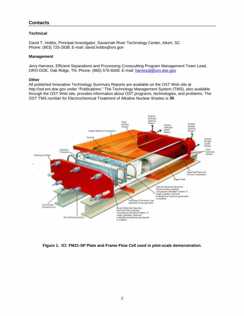
Figure 1. ICI FM21-SP Plate and Frame Flow Cell used in pilot-scale demonstration.
3
SECTION 2 TECHNOLOGY DESCRIPTION
Overall Process Definition
In an electrochemical reaction, charge is transferred at the interface between an electrode and thereactive species in a conductive liquid. An electrochemical reactor consists of an anode, a cathode, aconducting electrolyte, and power supply. At the cathode, electrons are passed from the electrode to thereacting species, resulting in a reduction in the oxidation state of the species. At the anode, electronspass from the reactive species to the electrode, resulting in an increase in the oxidation state. Theseoxidation state changes alter the chemical properties and form of the reactants. The reduced or oxidizedspecies can form a deposit on the electrode or desorb from the electrode surface and dissolve in the liquidphase or evolve as a gas. Electrochemical treatment is one possible technology for the destruction of nitrate and nitrite as well as theremoval of radionuclides and hazardous metals from alkaline waste solutions. In the electrochemicalreactor, nitrate and nitrite are reduced (at the cathode) to form nitrogen-containing gases: nitrogen,ammonia and nitrous oxide. Water is also reduced in a competing reaction at the cathode, producinghydrogen gas and hydroxide ion. These gases have low solubility in the alkaline salt solution and arereleased into the vapor phase, thus separating from the solution. Metal ions in the electrolyte may also bereduced at the cathode, forming solids deposited on the cathode surface or precipitated from solution. Atthe anode, the dominant reaction is the oxidation of hydroxide ions to form oxygen gas, with the oxidationof any organic species dispersed in the electrolyte being a beneficial side reaction. Oxidation of nitrite ionto nitrate also occurs at the anode if nitrite is present in solution. The chief effect of these chemical reactions on the waste solution is to replace each nitrite or nitrate ionwith hydroxide ion. No additional chemicals would be added to the waste. Greater than 99% of the nitrateand nitrite can be removed in either an undivided or a divided cell reactor. The rate of destruction and theoverall power consumption depend on the cell configuration, the current density, and the electrodematerials. Special procedures to prevent electrode poisoning are required if chromate is present in thewaste.
System Operation
The electrochemical process for removal of nitrate/nitrite from alkaline solution can be operated in eitheror two modes: undivided cell, or membrane-divided cell. Each mode has advantages and disadvantagesthat are summarized below. Both modes share the following characteristics:• capable of destroying >99% of nitrate and nitrite• compatible with Saltstone and caustic recycle processes• when no chromate is present, best results are obtained with a nickel cathode and a nickel anode• presence of chromate inhibits nitrate/nitrite reduction at high current density• chromate inhibition can be mitigated by
– periodic current reversal (undivided cell) (Jha, Weidner and White 1995)– using a lead cathode (divided cell) (Bockris and Kim 1995)– operating at low current density
• ammonia gas generated at cathode requires further treatment before release to the environment
Undivided cell advantages:• simpler facility design• lower power consumption (lower resistance between electrodes)• membrane lifetime is not an issue
Undivided cell disadvantages:• wasted current due to cycling of nitrate! " nitrite reaction at anode and cathode
4
• mixing of anode and cathode product gases (hydrogen, ammonia, oxygen, etc.)• longer induction period required before net nitrate destruction begins
Divided cell advantages:• destruction of nitrate at cathode begins immediately with power application• anodic and cathodic gases are collected separately• higher electrical efficiency by preventing reoxidation of reduced nitrogen species
Divided cell disadvantages:• higher power consumption resulting from higher cell resistance across the membrane• first batch requires added caustic as anolyte; later batches use catholyte product as anolyte• greater reactor complexity introduces more potential problems (e.g., membrane fouling, breakage and
disposal; feed and product streams for both anolyte and catholyte)
������������������������������������������������������������������������������������������������������������������������������������������������������������������������������������������������������������������������
���������������������������������������������������������������������������������������������������������������������������������������������������������������������
Pump Pump
CatholyteAnolyte
Flowmeter
ELECTROCHEMICAL CELL
Flowmeter Valve
Sampling Valve
in
out
����������������������������������������������������������������������������������������������������������������������������������������������
������������������������������������������������������������������������������������������������������������������������������
ENDOCAL Refrigerated
Circulating Bath
OMEGA Thermister
Thermometer
-
+
BOSS CONTROLLER(-) (+)
SHUNT
VOLTAGE METER
Flowmeter
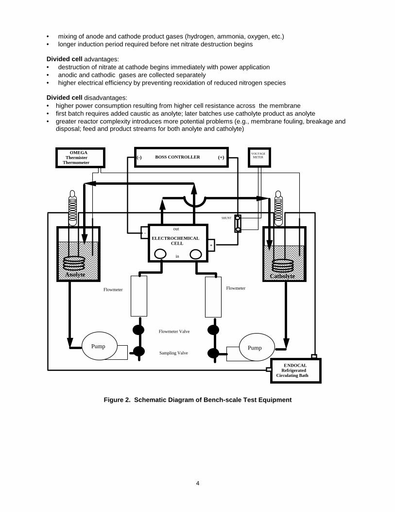
Figure 2. Schematic Diagram of Bench-scale Test Equipment
5
SECTION 3 PERFORMANCE
Demonstration Plan
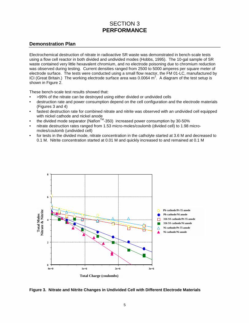
Electrochemical destruction of nitrate in radioactive SR waste was demonstrated in bench-scale testsusing a flow cell reactor in both divided and undivided modes (Hobbs, 1995). The 10-gal sample of SRwaste contained very little hexavalent chromium, and no electrode poisoning due to chromium reductionwas observed during testing. Current densities ranged from 2500 to 5000 amperes per square meter ofelectrode surface. The tests were conducted using a small flow reactor, the FM 01-LC, manufactured byICI (Great Britain.) The working electrode surface area was 0.0064 m2. A diagram of the test setup isshown in Figure 2. These bench-scale test results showed that:• >99% of the nitrate can be destroyed using either divided or undivided cells• destruction rate and power consumption depend on the cell configuration and the electrode materials
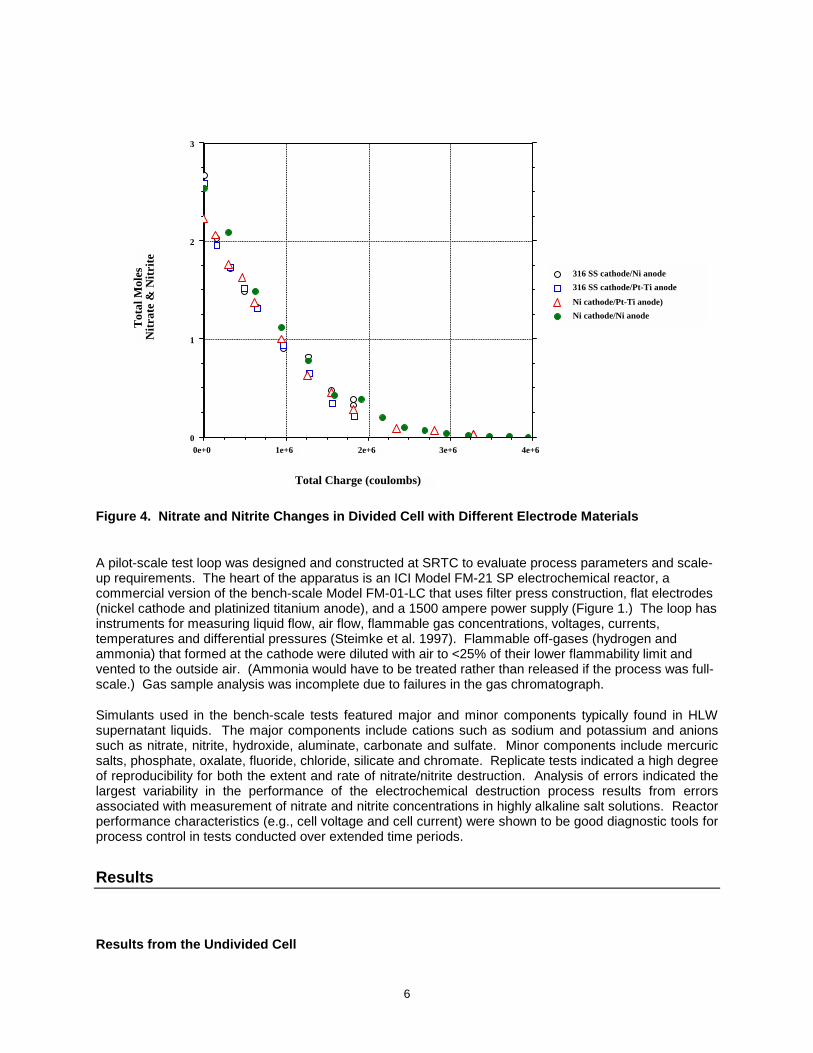
(Figures 3 and 4)• fastest destruction rate for combined nitrate and nitrite was observed with an undivided cell equipped
with nickel cathode and nickel anode• the divided mode separator (NafionTM-350) increased power consumption by 30-50%• nitrate destruction rates ranged from 1.53 micro-moles/coulomb (divided cell) to 1.98 micro-
moles/coulomb (undivided cell)• for tests in the divided mode, nitrate concentration in the catholyte started at 3.6 M and decreased to
0.1 M. Nitrite concentration started at 0.01 M and quickly increased to and remained at 0.1 M
3e+62e+61e+60e+0
����������������������������������������
��������������������������������������������������������������������������������
0
2
4
6
8
�����������������������������������������������������������������������������������������������������������������������������������
����������������������������������������������������������������������������������������������������������������������������������������������������������������������������������������������������������������������������������������������������������������������
�����������������������������������������������������������������������������������������������������������������������������������
Pb cathode/Ni anode
316 SS cathode/Pt-Ti anode316 SS cathode/Ni anode
Ni cathode/Pt-Ti anodeNi cathode/Ni anode
Pb cathode/Pt-Ti anode
Total Charge (coulombs)
T
otal
Mol
esN
itrat
e &
Nitr
ite
Figure 3. Nitrate and Nitrite Changes in Undivided Cell with Different Electrode Materials
6
4e+63e+62e+61e+60e+0
��������������������
��������������������
��������������������
0
1
2
3
�������������������������������������������������������������������������������������������������������������������������������������
�������������������������������������������������������������������������������������������������������������������������������������
316 SS cathode/Ni anode316 SS cathode/Pt-Ti anode
Ni cathode/Pt-Ti anode)Ni cathode/Ni anode
Total Charge (coulombs)
T
otal
Mol
esN
itrat
e &
Nitr
ite
Figure 4. Nitrate and Nitrite Changes in Divided Cell with Different Electrode Materials A pilot-scale test loop was designed and constructed at SRTC to evaluate process parameters and scale-up requirements. The heart of the apparatus is an ICI Model FM-21 SP electrochemical reactor, acommercial version of the bench-scale Model FM-01-LC that uses filter press construction, flat electrodes(nickel cathode and platinized titanium anode), and a 1500 ampere power supply (Figure 1.) The loop hasinstruments for measuring liquid flow, air flow, flammable gas concentrations, voltages, currents,temperatures and differential pressures (Steimke et al. 1997). Flammable off-gases (hydrogen andammonia) that formed at the cathode were diluted with air to <25% of their lower flammability limit andvented to the outside air. (Ammonia would have to be treated rather than released if the process was full-scale.) Gas sample analysis was incomplete due to failures in the gas chromatograph. Simulants used in the bench-scale tests featured major and minor components typically found in HLWsupernatant liquids. The major components include cations such as sodium and potassium and anionssuch as nitrate, nitrite, hydroxide, aluminate, carbonate and sulfate. Minor components include mercuricsalts, phosphate, oxalate, fluoride, chloride, silicate and chromate. Replicate tests indicated a high degreeof reproducibility for both the extent and rate of nitrate/nitrite destruction. Analysis of errors indicated thelargest variability in the performance of the electrochemical destruction process results from errorsassociated with measurement of nitrate and nitrite concentrations in highly alkaline salt solutions. Reactorperformance characteristics (e.g., cell voltage and cell current) were shown to be good diagnostic tools forprocess control in tests conducted over extended time periods.
Results
Results from the Undivided Cell
7
The treated SR simplified waste simulant contained 1.65 M sodium nitrate, 0.52 M sodium nitrite, and 1.11M sodium hydroxide. The process operated at a constant current of 735 amperes (A) (i.e., current densityof 3500 A/m2 ) for a period of 76 hours. Hydrogen production rates increased as the run progressed, andaveraged 7 moles/hr over the final 30 hours of the run. About 40% of the current was consumed in theproduction of hydrogen. After 76 hours, the concentration of nitrate was reduced to 0.6 M and nitrite tonearly zero. Nitrate initially increased to a maximum of 1.9 M as nitrite decreased to 0.1 M during the first10 hours of operation. Results from the Divided Cell The catholyte feed was initially 1.87 M sodium nitrate, 0.58 M sodium nitrite, and 1.26 M sodiumhydroxide. Anolyte feed was initially 5.03 M sodium hydroxide. The process ran at constant current of735 A for 38 hours, but current dropped to zero by 42 hours due to depletion of sodium hydroxide from theanolyte. Hydrogen evolution at the cathode averaged about 2 moles per hour, and consumed about 20%of the total charge. At test conclusion, anolyte concentration of sodium hydroxide was close to zerowhereas catholyte concentration was 5.7 M; catholyte nitrate was 0.8 M and catholyte nitrite was 0.5 M(and remained constant after only 4 hours of run time.) Comparison with Prior Work The Electrosynthesis Company tested an ICI FM-21 SP Electrolyzer on simulated Hanford and SR wastein both divided and undivided modes (Chai, Hartsough and Genders 1995). The SR simulant employed inthis testing contained a complex mixture of sodium salts including 0.77 g/L of sodium chromate. Resultsfrom this pilot-scale testing confirmed the inhibiting effect of chromate previously observed in bench-scaletests. After a 20-hour induction period during which time no nitrate was destroyed in a divided cell, nitratedropped steadily to about 33% of the initial concentration over the next 30 hours of operation. In anundivided cell, only 5% of the nitrate was destroyed after 40 hours of cell operation. Similar results wereobserved with the Hanford simulant.
8
SECTION 4 TECHNOLOGY APPLICABILITY AND ALTERNATIVES
Competing Technologies
The baseline technology is defined as the direct conversion of SR low-activity waste (LAW) into Saltstonewithout prior conversion of nitrate and nitrite into hydroxide. The resulting Saltstone would thereforecontain leachable nitrate and nitrite ions that pose a threat to groundwater at the final disposal site. Ifspecial containment vaults are required to isolate the Saltstone waste and thereby prevent groundwatercontamination, disposal costs could be substantially higher than for disposal in concrete vaults. Alternatives to the electrochemical process for treating nitrate and nitrite wastes also exist, and these wererecently reviewed (RCS Corp. 1997). Two technologies were judged to be attractive competitors:vitrification, and nitrate to ammonia and ceramic (NAC). Because neither technology is compatible withthe Saltstone waste form, they will not be discussed further in this report. Greater uncertainties are alsoassociated with these technologies than with electrochemical reduction. In comparison to the baseline (non-treatment), electrochemical reduction of nitrate/nitrite indecontaminated salt solution at SR offers the following: Advantages• >90% removal of nitrate and nitrite significantly lowers the threat of leaching from the final waste form• production of hydroxide ion is compatible with the caustic recycle technology proposed for tank waste
(U. S. DOE 1999) and the hydroxide concentrate may be useful in waste treatment applications• organic compounds in the waste stream are simultaneously destroyed at the anode Disadvantages• ammonia and nitrous oxide gas produced by electrolysis will require treatment prior to discharge• hydrogen gas produced at the cathode must be diluted to prevent explosions• metals (including some radionuclides) in wastes may deposit on the electrodes and reduce
electrolysis efficiency• substantial treatment cost
Technology Applicability
Electrochemical destruction of aqueous nitrate in wastes may be useful for managing non-radioactivehazardous wastes such as those from the chemical, plating, pulp and paper, and electronics industries.Electrical energy costs can be the decisive factor in technology selection. DOE sites that store large amounts of alkaline waste (Savannah River and Hanford) are the majorpotential users of this technology. Treatment of highly acidic wastes is not as attractive, as protons wouldcompete with nitrate and nitrite for reduction at the cathode.
Patents/Commercialization/Sponsor
The Department of Energy Office of Science and Technology funded the development of the electrolyticdenitration technology through the Efficient Separations and Processing Crosscutting Program.Participating institutions included: Savannah River Technology Center; Electrosynthesis Company, Inc.;University of South Carolina; University of Tennessee; ICI, Ltd.; Pacific Northwest National Laboratory;Texas A&M University; and the E. I. DuPont de Nemours and Co., Inc.
9
SECTION 5 COST
Methodology
Bechtel Savannah River, Inc., developed a preconceptual design for an electrochemical denitrationsystem capable of treating 2 million-gallons per year (mgy) of alkaline nitrate-bearing waste (BechtelSavannah River, Inc. 1996). The design was doubled in capacity and amended to include abatement ofthe ammonia discharges and partial recovery of hydroxide concentrate by RCS (RCS Corp. 1997). Costanalysis in the following sections is drawn principally from the RCS report. Costs for ammonia abatementare unknown and were not included in the estimate by RCS. RCS also assumed that 0.8 mgy of the 4mgy of denitration product would be recovered as hydroxide concentrate for use in waste pretreatmentapplications. However, no costs or benefits were estimated for this facility by RCS. Hydroxide recoveryhad not been included in the original Bechtel flowsheet.
Cost Analysis
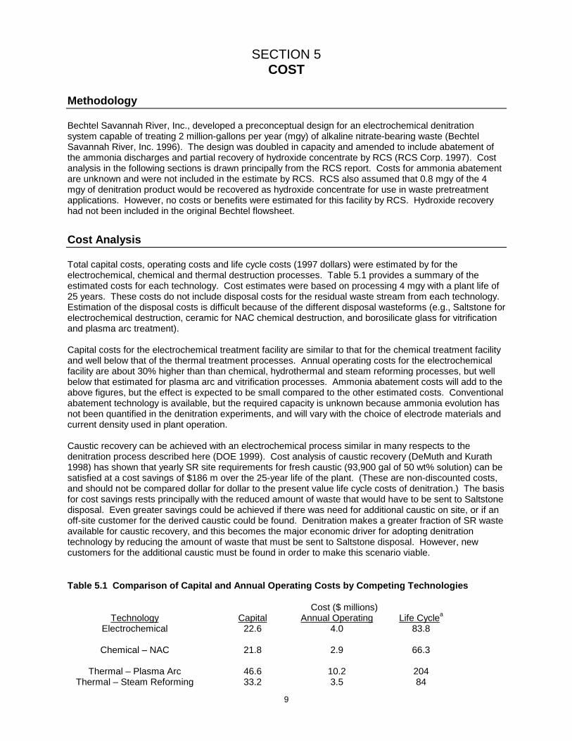
Total capital costs, operating costs and life cycle costs (1997 dollars) were estimated by for theelectrochemical, chemical and thermal destruction processes. Table 5.1 provides a summary of theestimated costs for each technology. Cost estimates were based on processing 4 mgy with a plant life of25 years. These costs do not include disposal costs for the residual waste stream from each technology.Estimation of the disposal costs is difficult because of the different disposal wasteforms (e.g., Saltstone forelectrochemical destruction, ceramic for NAC chemical destruction, and borosilicate glass for vitrificationand plasma arc treatment). Capital costs for the electrochemical treatment facility are similar to that for the chemical treatment facilityand well below that of the thermal treatment processes. Annual operating costs for the electrochemicalfacility are about 30% higher than than chemical, hydrothermal and steam reforming processes, but wellbelow that estimated for plasma arc and vitrification processes. Ammonia abatement costs will add to theabove figures, but the effect is expected to be small compared to the other estimated costs. Conventionalabatement technology is available, but the required capacity is unknown because ammonia evolution hasnot been quantified in the denitration experiments, and will vary with the choice of electrode materials andcurrent density used in plant operation. Caustic recovery can be achieved with an electrochemical process similar in many respects to thedenitration process described here (DOE 1999). Cost analysis of caustic recovery (DeMuth and Kurath1998) has shown that yearly SR site requirements for fresh caustic (93,900 gal of 50 wt% solution) can besatisfied at a cost savings of $186 m over the 25-year life of the plant. (These are non-discounted costs,and should not be compared dollar for dollar to the present value life cycle costs of denitration.) The basisfor cost savings rests principally with the reduced amount of waste that would have to be sent to Saltstonedisposal. Even greater savings could be achieved if there was need for additional caustic on site, or if anoff-site customer for the derived caustic could be found. Denitration makes a greater fraction of SR wasteavailable for caustic recovery, and this becomes the major economic driver for adopting denitrationtechnology by reducing the amount of waste that must be sent to Saltstone disposal. However, newcustomers for the additional caustic must be found in order to make this scenario viable.
Table 5.1 Comparison of Capital and Annual Operating Costs by Competing Technologies
Cost ($ millions)Technology Capital Annual Operating Life Cyclea
Electrochemical 22.6 4.0 83.8
Chemical – NAC 21.8 2.9 66.3
Thermal – Plasma Arc 46.6 10.2 204Thermal – Steam Reforming 33.2 3.5 84
10
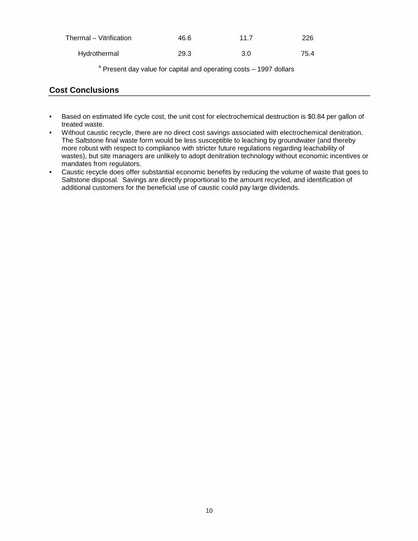
Thermal – Vitrification 46.6 11.7 226
Hydrothermal 29.3 3.0 75.4
a Present day value for capital and operating costs – 1997 dollars
Cost Conclusions
• Based on estimated life cycle cost, the unit cost for electrochemical destruction is $0.84 per gallon oftreated waste.
• Without caustic recycle, there are no direct cost savings associated with electrochemical denitration.The Saltstone final waste form would be less susceptible to leaching by groundwater (and therebymore robust with respect to compliance with stricter future regulations regarding leachability ofwastes), but site managers are unlikely to adopt denitration technology without economic incentives ormandates from regulators.
• Caustic recycle does offer substantial economic benefits by reducing the volume of waste that goes toSaltstone disposal. Savings are directly proportional to the amount recycled, and identification ofadditional customers for the beneficial use of caustic could pay large dividends.
11
SECTION 6 REGULATORY AND POLICY ISSUES
Regulatory Considerations
Decontaminated salt solution at SR would be classified as hazardous waste (U. S. EnvironmentalProtection Agency Hazardous Waste Code D002) on the basis of its having a pH>12.5. (See Code ofFederal Regulations 261.22 for the definition of D002.) The waste is therefore subject to the Resourceand Conservation Recovery Act (RCRA). The electrochemical denitration process would require thefollowing:• RCRA Part B permit• National Environmental Policy Act (NEPA) review• Air pollution permit from the South Carolina Dept. of Health and Environmental Control• Radioactive materials license Secondary Waste Streams Regulatory Considerations If caustic recycle is performed in conjunction with denitration, the caustic recycle product would not beclassified as a hazardous waste because it is used as a product in tank waste treatment. However, on-site uses are not large enough to use all of the caustic that could be recovered. There are many off-sitecommercial uses for decontaminated caustic, but regulatory and institutional barriers restrict the release ofmaterials derived from radioactive wastes. There is no de minimus level specified that would allowdesignation of formerly radioactive materials as non-radioactive. All liquid waste residuals would be solidified in Saltstone and would meet applicable environmentalstandards, including the Saltstone waste acceptance criteria and the land disposal restrictions of RCRA.Denitration would create a Saltstone product that poses much less risk to groundwater than would thebaseline product. Gaseous emissions from the electrolyzers would include ammonia, nitrous oxide, hydrogen, and oxygen.Commercial air pollution control equipment should be adequate to reduce emission levels to acceptancestandards. CERCLA Considerations The Comprehensive Environmental Response, Compensation and Liability Act (CERCLA) evaluationcriteria are addressed for this technology as follows: • Overall Protection of Human Health and the Environment: The technology removes nitrate and nitrite
from liquid waste that will ultimately be solidified as Saltstone. The resulting solid will be much lesssusceptible to leaching by groundwater than is Saltstone formed from untreated liquid waste.
• Compliance with applicable or relevant and appropriate requirements (ARARs) can be met.• Long-term Effectiveness will be enhanced by the technology, with the residual final waste form
(Saltstone) posing less risk to area groundwater.• Reduction of Volume will occur to the extent that caustic recycle is used in conjunction with
denitration, thereby reducing the volume of disposed Saltstone.• Short-term Effectiveness: Construction of a denitration facility could delay Saltstone creation and
disposal, but modular components and availability of all needed parts make this risk small.• Implementability would require a decision on the mode of operation, choice of electrode materials and
membranes (if needed), and the use of caustic recycle as part of the operation. If flow-through foamelectrodes are used, some development work will be required.
• Costs have been addressed in Section 5.• State and Community Acceptance should be favorable towards this technology. Off-site use of the
caustic product may require approval and negotiation.
12
Safety, Risks, Benefits, and Community Reaction
Worker Safety Electrolysis has been used safely by industry in other applications for over a century. All applicable workersafety standards, including those specified in DOE Order 5480.1A, could be satisfied. Theelectrochemical process would use large amounts of electricity and pose electrical hazards (low voltage,high current) to personnel. Electrical hazards could be effectively mitigated, however, by proper designand adherence to standard operating procedures. Caustic liquids can cause severe burns to the skin and are extremely dangerous to the eyes. Goggles,gloves, and rubber boots in conjunction with Level B or C personnel protection are required. The causticrecycle process could be remotely operated and monitored, thus minimizing the potential for workercontact. Electrolysis would require rigorous engineering controls to mitigate process hazards. The electrochemicaltreatment of nitrates would result in the evolution of significant quantities of ammonia and hydrogen gases.Ammonia gas is both flammable and toxic. Hydrogen gas is flammable and explosively combustible ifconcentrations are allowed to exceed critical limits. Community Safety The risk to the community is low. Secondary containment for piping and storage tanks will reduce thepotential for accidental release of liquid caustic. An off-gas system for treating gaseous emissions ofammonia and hydrogen can be constructed using commercially available air pollution control equipment.
SECTION 7 LESSONS LEARNED
13
Implementation Considerations
• Advantages and limitations of undivided and divided cell configurations have been investigated. Asystems engineering review is recommended to determine optimum configuration for large-scalecommercialization.
• Implementation of this technology should consider radioactive applications where contactmaintenance is allowed. Complete remote operation of the relatively complex electrochemicalreactors appears to be cost-prohibitive for treating large volumes of radioactive waste (i.e., more than1 million gallons per year).
• High surface-area electrodes will be required if low current density is used. Bench-scale studies at theUniversity of South Carolina have yielded good results with a nickel foam flow-through electrode (Jha,Weidner and White 1995). Undesired hydrogen generation at the cathode is also reduced by usingfoam electrodes.
• Hexavalent chromium is present in small concentration in SR waste, and this inhibits efficientnitrate/nitrite reduction at high current densities. Additional development is required to determine themost effective operating strategy (e.g., cathode material, periodic current reversal and lower currentdensity) to counteract the effects of chromium inhibition
Technology Limitations and Needs for Future Development • Problems of gas trapping in the pores of metal foam electrodes need to be addressed before these
flow-through electrodes can be used with confidence.• Identification of a cathode material that exhibits high selectivity for nitrogen production at high current
density would reduce or eliminate the need for off-gas treatment• Ammonia gas is sufficiently soluble in basic aqueous solution to require special methods for removing
it from the catholyte product before sending that product to the anode for oxidation.• Reactor performance and lifetime in treating complex waste compositions need to be determined.
Technology Selection Considerations
Pilot-scale testing of the technology with radioactive wastes may be required to demonstrate thetechnology and provide data with sufficient confidence to complete full-scale engineering design. Animportant need to enhance the acceptance of this technology is the development of a cathode materialthat promotes the formation of nitrogen (rather than ammonia or nitrous oxide) at high current density inthe presence of hexavalent chromium. The need for denitration technology depends strongly on release criteria for hazardous nitrates andnitrites. If these criteria change in the future, the need for and attractiveness of an electrolytic denitrationprocess operating at low temperature and pressure could increase significantly
14
APPENDIX A REFERENCES
Bechtel Savannah River, Inc. 1995. Preconceptual Design Study for the Salt Solution Electrochemical
Denitration and Caustic Recovery Facility. WAD # LIW2EE002, Rev. C. Aiken, SC: SavannahRiver Technology Center.
Bockris, J., and J. Kim. 1995. Packed-Bed and Fluidized-Bed Electrodes. WSRC-TR-95-0310. Aiken, SC:
Savannah River Technology Center. Bockris, J. O’M, and J. Kim. 1997. Effect of Contact Resistance between Particles on the Current
Distribution in a Packed Bed Electrode. J. Appl. Electrochem. 27: 890-901. Bockris, J. O’M., and J. Kim. 1997. Electrochemical Treatment of Low-level Nuclear Wastes. J. Appl.
Electrochem. 27: 623-634. Chais, D.,D. Hartsough, and J. D. Genders. 1995. Electrochemical Processing of Hanford and SRS
Waste Simulants Using an ICI FM21-SP Pilot Scale Flow Cell. WSRC-TR-95-0405. Aiken, SC:Savannah River Technology Center.
Coleman, D. H., R. E. White, and D. T. Hobbs. 1994. A Parallel-Plate Electrochemical (PPER) Model for
the Destruction of Nitrate and Nitrite in Alkaline Waste Solutions. Proc. Electrochem. Soc. 94-22:374-411.
Coleman, D. H., R. E. White, and D. T. Hobbs. 1995. A Parallel-Plate Electrochemical (PPER) Model for
the Destruction of Nitrate and Nitrite in Alkaline Waste Solutions. J. Electrochem. Soc. 142:1152-1161.
DeMuth, S., and D. Kurath. 1998. Cost Benefit of Caustic Recycle for Tank Waste Remediation at the
Hanford and Savannah River Sites. LA-UR-98-3339. Los Alamos, NM: Los Alamos NationalLaboratory.
Duarte, H. A., K. Jha, and J. W. Weidner. 1998. Electrochemical Reduction of Nitrates and Nitrites in
Alkaline Media in the Presence of Hexavalent Chromium. J. Appl. Electrochem. 28:811-817. Genders, J. D., D. Hartsough, and D. T. Hobbs. 1996. Electrochemical Reduction of Nitrates and Nitrities
in Alkaline Nuclear Waste Solutions. J. Appl. Electrochem. 26:1-9. Hobbs, D. T. 1995. Electrolytic Denitration of Radioactive Savannah River Site Waste (U). WSRC-TR-95-
0176. Aiken, SC: Savannah River Technology Center. Hobbs, D. T., and M. A. Ebra. 1987. Electrochemical Processing of Low-Level Waste Solutions. Proc.
Symp. Waste Manage. 87-3:161-165. Hobbs, D. T., and M. A. Ebra. 1987. Electrochemical Processing of Alkaline Nitrate and Nitrite Solutions.
AIChE Symp. Ser. 83 (254, Electrochem. Engr. Appl.): 149-155. Jha, K., J. W. Weidner, and R. E. White. 1995. Evaluation of a Porous Cathode used for the
Electrochemical Reduction of Nitrates and Nitrites in Liquid Wastes. WS RC-TR-0438. Aiken,SC: Savannah River Technology Center.
Jha, K., and J. W. Weidner. 1999. Evaluation of Porous Cathodes for the Electrochemical Reduction of
Nitrates and Nitrites in Alkaline Waste Streams. J. Appl. Electrochem. 29:1305-1315. Kalu, E. E., R. E. White and D. T. Hobbs. 1996. Use of a Hydrogen Anode for Nitrate Waste Destruction.
J. Electrochem. Soc. 143:3094-3099.
15
Li, H. –L., J. Q. Chambers, and D. T. Hobbs. 1988. Electroreduction of Nitrate Ions in ConcentratedSodium Hydroxide Solutions at Lead, Zinc, Nickel, and Phthalocyanine-Modified Electrodes. J.Appl. Electrochem. 18:454-458.
Li, H. –L., D. H. Robertson, J. Q. Chambers and D. T. Hobbs. 1988. Electrochemical Reduction of Nitrate
and Nitrite in Concentrated Sodium Hydroxide at Platinum and Nickel Electrodes. J. Electrochem.Soc. 135:1154-1158.
Li, H. –L., J. Q. Chambers, and D. T. Hobbs. 1988. Electrocatalytic Reduction of Nitrate and Nitrite at
NafionTM-Coated Electrodes in Concentrated Sodium Hydroxide Solution. J. Electroanalyt. Chem.And Interfacial Electrochem. 256:447-453.
Li, H. –L., W. C. Anderson, J. Q. Chambers, and D. T. Hobbs. 1989. Electrocatalytic Reduction of Nitrate
in Sodium Hydroxide Solution in the Presence of Low-Valent Cobalt-Cyclam Species. Inorg.Chem. 28:863-868.
Prasad, S., J. W. Weidner, and A. E. Farell. 1995. A Boundary-Layer Model of a Parallel-Plate
Electrochemical Reactor for the Destruction of Nitrates and Nitrites in Alkaline Waste Solutions.J. Electrochem. Soc. 142:3815-3824.
RCS Corporation. 1997. Evaluation of Nitrate and Nitrite Destruction/Separation Technologies. WSRC-
OS-97-00008. Aiken, SC: Savannah River Technology Center. Steimke, J. L., D. T. Hobbs, M. D. Fowley, and T. J. Steeper. 1997. Results from Tests of TFL
Electrochemical Reactor (U).. WSRC-TR-97-0196. Aiken, SC: Savannah River TechnologyCenter.
Steimke, J. L., D. T. Hobbs, and T. J. Steeper. 1997. Pilot Scale Testing of Electrochemical Processes
for Nitrate and Nitrite Destruction and Caustic Recovery. Electrochem. Process. Technol., Int.Forum, Electrolysis Chem. Ind., 11:429-440.
Tsintavis, C., H. –L. Li, J. Q. Chambers, and D. T. Hobbs. 1990. Isomerization and Conformational
Equilibria Coupled to Electron Transfer in a Macrocyclic Cobalt (III/II)-Cyclam System in SodiumHydroxide Solution. Inorg. Chimica Acta. 171:1-3
Tsintavis, C., H. –L. Li, J. Q. Chambers, and D. T. Hobbs. 1991. Electrochemistry of cis- and trans-
1,4,8,11-Tetraazacyclo-tetradecane Complexes of Cobalt (III) at Gold Electrodes in HydroxideSolution. J. Phys. Chem. 95:289-297.
U. S. Department of Energy. 1999. Caustic Recycle. DOE/EM-0494. Wingard, D. A., J. W. Weidner, J. W. Van Zee, and D. T. Hobbs. 1994. A Simple Model of the Batch
Electrochemical Reduction of NO3 -/NO2- Waste. Proc. Electrochem. Soc. 94-22:358-373.

17
APPENDIX BACRONYMS AND ABBREVIATIONS
A AmpereARARs Applicable or relevant and appropriate requirementsCERCLA Comprehensive Environmental Response, Compensation and Liability ActD&D Deactivation and decommissioninggal GallonG/L Gram per literHLW High-level wastehr HourLAW Low-activity wastem Metermgy Million gallons per yearM Molarity (moles of solute per liter of solution)MWh MegaWatt-hourNafion-350 Membrane manufactured by E. I. DuPont, Inc.NEPA National Environmental Policy ActO&M Operation and MaintenanceRCRA Resource and Conservation Recovery Act$…m Million dollarsSR Savannah River Site (Aiken, SC)SRTC Savannah River Technology CenterWt% Weight per cent