Electrochemical Characterisation to Study the Pitting Corrosion...
27
1 Electrochemical Characterisation to Study the Pitting Corrosion Behaviour of Beryllium J. S. Punni * AWE, Reading UK 1. Introduction Beryllium has widespread uses in aerospace industry as it has attractive mechanical properties, a high melting point (1289 °C), a low density (1.85 g/cc), high specific heat capacity and thermal conductivity. It has a hexagonal close packed (hcp) structure and due to its low neutron cross section it is widely used for nuclear applications. To achieve the required mechanical properties beryllium is produced by vacuum hot pressing in the temperature range 1000 to 1100°C, using a high purity and fine grained beryllium powder. To get stress relief, the material is subsequently heat treated at 800°C; this also serves to remove elemental aluminium at grain boundaries in material structure, by converting it to the intermetallic form AlFeBe 4 . A proper balance between Fe and Al is required to avoid ‘hot shortness’ due to the presence of elemental aluminium at the grain boundaries. The principle contaminants within commercial beryllium are oxygen (as beryllium oxide), carbon, silicon, iron, aluminium and magnesium. Silicon, iron and aluminium principally come from the ore, although additional iron may be contributed from billet machining operations. Magnesium arises primarily from reduction of beryllium fluoride using magnesium to produce beryllium metal. Carbon arises principally from casting operations, which use graphite moulds. Oxygen is always present as an oxide film on powder particles. Other elements are also present but generally at very low levels. Past studies have shown that beryllium is susceptible to pitting corrosion in the presence of chloride, fluoride and sulphate ions (Hill, et al., 1996, 1998; Stonehouse & Weaver, 1965). This is due to the breakdown of passive film at localised sites resulting in sporadic pits. The pitting is an insidious form of corrosion since it can proceed unnoticed and can lead to a catastrophic component failure. During the pitting process most of the metal surface remains passive and acts as the cathodic site for a small anodic area inside the pit which leads to accelerated attack in this location. Pitting corrosion is a localised form of corrosion by which cavities and holes are produced in the material, which are generally plugged with corrosion products. Corrosion, in general, is an electrochemical process in which electrons are generated and consumed at the corroding metal surface. This process consists of (i) an anodic site at the metal surface where metal is * © British Crown Owned Copyright 2011/MOD www.intechopen.com
Transcript of Electrochemical Characterisation to Study the Pitting Corrosion...
1
Electrochemical Characterisation to Study the Pitting Corrosion Behaviour of Beryllium
J. S. Punni* AWE, Reading
UK
1. Introduction
Beryllium has widespread uses in aerospace industry as it has attractive mechanical
properties, a high melting point (1289 °C), a low density (1.85 g/cc), high specific heat capacity and thermal conductivity. It has a hexagonal close packed (hcp) structure and due to its low neutron cross section it is widely used for nuclear applications. To achieve the required mechanical properties beryllium is produced by vacuum hot pressing in the temperature range 1000 to 1100°C, using a high purity and fine grained beryllium powder. To get stress relief, the material is subsequently heat treated at 800°C; this also serves to remove elemental aluminium at grain boundaries in material structure, by converting it to the intermetallic form AlFeBe4. A proper balance between Fe and Al is required to avoid ‘hot shortness’ due to the presence of elemental aluminium at the grain boundaries.
The principle contaminants within commercial beryllium are oxygen (as beryllium oxide), carbon, silicon, iron, aluminium and magnesium. Silicon, iron and aluminium principally come from the ore, although additional iron may be contributed from billet machining operations. Magnesium arises primarily from reduction of beryllium fluoride using magnesium to produce beryllium metal. Carbon arises principally from casting operations, which use graphite moulds. Oxygen is always present as an oxide film on powder particles. Other elements are also present but generally at very low levels.
Past studies have shown that beryllium is susceptible to pitting corrosion in the presence of chloride, fluoride and sulphate ions (Hill, et al., 1996, 1998; Stonehouse & Weaver, 1965). This is due to the breakdown of passive film at localised sites resulting in sporadic pits. The pitting is an insidious form of corrosion since it can proceed unnoticed and can lead to a catastrophic component failure. During the pitting process most of the metal surface remains passive and acts as the cathodic site for a small anodic area inside the pit which leads to accelerated attack in this location.
Pitting corrosion is a localised form of corrosion by which cavities and holes are produced in the material, which are generally plugged with corrosion products. Corrosion, in general, is an electrochemical process in which electrons are generated and consumed at the corroding metal surface. This process consists of (i) an anodic site at the metal surface where metal is
*© British Crown Owned Copyright 2011/MOD
www.intechopen.com
Pitting Corrosion
2
converted into metal ions by losing electrons. In the case of beryllium the anodic reaction is as follows:
Be = Be2+ + 2e- (1)
Beryllium is a reactive metal having a standard potential of Eo = -1.85V and it lies between aluminium (-1.66V) and magnesium (-2.37V) in the reactive series (Kaye & Laby, 1978)
i. A cathodic site at the metal surface where a complementary reaction to consume excess electrons takes place which could be either
O2 + 2H2O + 4e- = 4OH- (2)
At Eo = +1.23V – 0.0591 pH at 25°C or
2H+ + 2e- = H2 (3)
In acidic conditions, at Eo = +0.0V – 0.0591 pH at 25°C
ii. A conductor to conduct electrons between the anode and cathode and (iv) an electrolyte to provide a medium for transporting ionic products away from the metal surface.
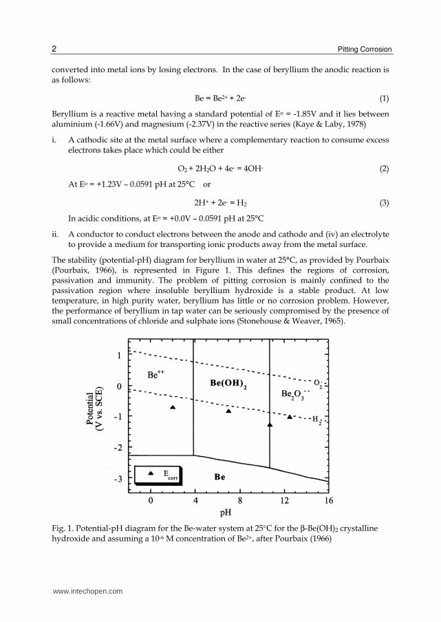
The stability (potential-pH) diagram for beryllium in water at 25°C, as provided by Pourbaix (Pourbaix, 1966), is represented in Figure 1. This defines the regions of corrosion, passivation and immunity. The problem of pitting corrosion is mainly confined to the passivation region where insoluble beryllium hydroxide is a stable product. At low temperature, in high purity water, beryllium has little or no corrosion problem. However, the performance of beryllium in tap water can be seriously compromised by the presence of small concentrations of chloride and sulphate ions (Stonehouse & Weaver, 1965).
Fig. 1. Potential-pH diagram for the Be-water system at 25°C for the β-Be(OH)2 crystalline hydroxide and assuming a 10-6 M concentration of Be2+, after Pourbaix (1966)
www.intechopen.com
Electrochemical Characterisation to Study the Pitting Corrosion Behaviour of Beryllium
3
2. Review of beryllium corrosion
2.1 Background
Pitting corrosion of beryllium in moist air has been reviewed by several authors (Stonehouse & Weaver, 1965; Miller & Boyd, 1968). Beryllium has adequate corrosion resistance for use in many engineering applications due to the formation of a protective oxide film when exposed to air. The metal will normally remain bright for years upon exposure to the atmosphere. The oxide (BeO) formed on the surface of beryllium is resistant to cracking or spalling because it grows inward and it is in a state of compression (due to its volume being 1.68 times larger than the metal it occupies). However, two prime situations were described by Mueller and Adolphson (1979) under which beryllium was found susceptible to pitting corrosion. The first is when beryllium has carbide particles exposed to moist air which produce active sites for corrosion. This was evidenced by the white corrosion products developed at sites occupied by these inclusions on beryllium under storage conditions. The second is when the surface of beryllium is contaminated with chloride and sulphate ions which may be introduced from human contact, contaminated air, rain water, cleaning solvent or certain packaging materials. A study by Stonehouse and Beaver using humidity cabinet experiments evaluated that machined beryllium (having surface residue deposits) was susceptible to pitting corrosion.
An initial study on the corrosion of beryllium in water focused on reactor environments where beryllium was used as a neutron reflector, and is not available in the general literature. Although beryllium corrosion rates were high in some of the simulated environments, service life for beryllium reflectors exposed to high purity irradiated water was reported to be good. There was no major problem of coupling beryllium with aluminium and stainless steel (Miller & Boyd, 1968). Another study was conducted (Flitton et al., 2002) as part of nuclear waste disposal, to understand beryllium corrosion as a result of being placed underground. Beryllium (99% pure) coupons were buried 4 and 10 feet deep underground. The general loss of material was measured at the rate 2 µm and 7 µm per year respectively, and the maximum pit depth at 4 feet underground depth was recorded as 153 µm. In some other instances where beryllium components were stored in uncontrolled moist environments, corrosion pits as deep as 250 µm were detected.
It has generally been recommended (Mueller & Adolphson, 1979; Stonehouse & Weaver, 1965) that for beryllium, the use of tap water should be minimised, metal surfaces should be as clean as possible, and excessive machine damage should be avoided. The storage of finished beryllium components should be maintained in polythene bags with a desiccant to maintain a dry atmosphere and in humidity controlled room. Where corrosion conditions are expected in service, the use of chromate coating and anodic films can be beneficial.
2.2 Effect of pH and chloride ion concentration
Electrochemical techniques were widely used in the past (Hill, et al., 1996, 1998; Punni & Cox, 2010; Lillard, 2000) to characterise pitting corrosion behaviour of beryllium in aggressive aqueous environments. In aqueous salt solutions beryllium develops a passive hydrated oxide film, either Be(OH)2 or its hydrate (BeO (H2O)x) (Vaidya et al. 1999) Electrochemical impedance spectroscopy (EIS) experiments had shown that the oxide growth rate on beryllium was 6.4 angstroms/V over the range of 0–4V. This barrier layer is quickly disrupted at localised sites in the presence of aggressive ions in the environment (Hill et al., 1998).
www.intechopen.com
Pitting Corrosion
4
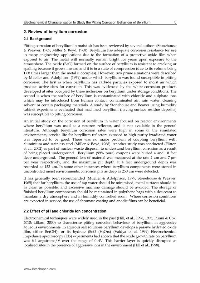
The passivity and pitting of commercially produced beryllium has been studied extensively in chloride solutions. The key points for a typical cyclic polarisation curve from a recent polarisation study (Punni & Cox, 2010) for a commercial beryllium are displayed in Figure 2. It was observed that the anodic polarisation was characterised by a region of passivity followed by a logarithmic increase in the current density, which corresponded to the onset of pitting corrosion (Epit).
`
Fig. 2. Typical cyclic polarisation curve for beryllium metal in 0.0001M KCl solution, sweep rate of 20mV/min, after Punni & Cox (2010)
A previous electrochemical study (Hill et al., 1996, 1998) in sodium chloride (NaCl) solution of varying chloride ion concentrations (from 0.0001 to 1M) showed that on increasing the chloride concentration, both pitting potential and repassivation potential decreased progressively and at 1M NaCl, the pitting commenced at open circuit conditions. A logarithmic relationship between pitting potential (in mV) and chloride concentration (in morality) was presented as given below.
Epit = - 67 log [Cl-1] -1010 (4)
The effect of pH on pitting corrosion behaviour of beryllium was studied by Hill and co-workers (1998). Beryllium was found to be passive in the pH range from 2 to 12.5 but it was susceptible to general attack below a pH of 2. The surface of samples exposed to pH 1 solutions were characterised by thick, black deposits over the entire surface. There was an increase in pitting potential with increase in pH. The total change in pitting potential over the pH range 2 to 12.5 was ~35 mV.
According to another investigation (Friedman and Hanafee, 2000) the change in pitting potential was rather greater ~90 mV over the same sort of pH range. This investigation also
-1050
-1000
-950
-900
-850
-800
-750
-700
-650
-600
-550
0 0 0 0 0 0 0
Current Density (mA/cm2)
Po
ten
tial
(mV
, S
CE
)
Pitting Potential (Epit)
Repassivation Potential (Erepass)
Open Circuit Potential (OCP)
Passivation Current (Ipass)
Start Finish
10-7
10-6
10-4
10-3
10-2
10-1
10-5
www.intechopen.com
Electrochemical Characterisation to Study the Pitting Corrosion Behaviour of Beryllium
5
found that chloride concentration in the range 0.001 to 0.1M NaCl did not have a significant effect on corrosion of beryllium. This conclusion was based on the observation that there was not much difference in passive range. It was stated that the size of the passive range, or the ability of a solution to break the oxide layer on the surface of the beryllium, appeared to be a function of pH, and not of chloride concentration. This result on chloride effect is not in agreement with the findings of Hill and co-workers (1996) and a recent investigation by Punni and Cox (2010).
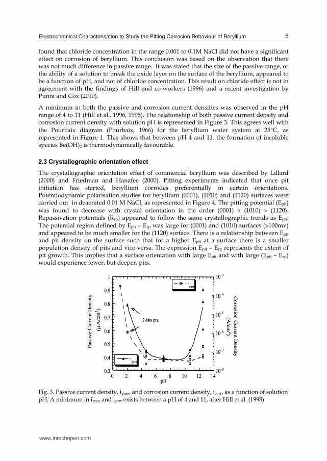
A minimum in both the passive and corrosion current densities was observed in the pH range of 4 to 11 (Hill et al., 1996, 1998). The relationship of both passive current density and corrosion current density with solution pH is represented in Figure 3. This agrees well with
the Pourbaix diagram (Pourbaix, 1966) for the beryllium water system at 25°C, as represented in Figure 1. This shows that between pH 4 and 11, the formation of insoluble species Be(OH)2 is thermodynamically favourable.
2.3 Crystallographic orientation effect
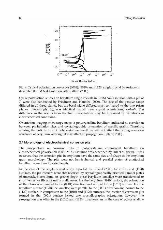
The crystallographic orientation effect of commercial beryllium was described by Lillard (2000) and Friedman and Hanafee (2000). Pitting experiments indicated that once pit initiation has started, beryllium corrodes preferentially in certain orientations. Potentiodynamic polarisation studies for beryllium (0001), (1010) and (1120) surfaces were carried out in deaerated 0.01 M NaCl, as represented in Figure 4. The pitting potential (Epit)
was found to decrease with crystal orientation in the order (0001) > (1010) > (1120). Repassivation potentials (Rrp) appeared to follow the same crystallographic trends as Epit. The potential region defined by Epit – Erp was large for (0001) and (1010) surfaces (>100mv) and appeared to be much smaller for the (1120) surface. There is a relationship between Epit and pit density on the surface such that for a higher Epit at a surface there is a smaller population density of pits and vice versa. The expression Epit – Erp represents the extent of pit growth. This implies that a surface orientation with large Epit and with large (Epit – Erp) would experience fewer, but deeper, pits.
Fig. 3. Passive current density, ipass, and corrosion current density, icorr, as a function of solution pH. A minimum in ipass and icorr exists between a pH of 4 and 11, after Hill et al. (1998)
www.intechopen.com
Pitting Corrosion
6
Fig. 4. Typical polarisation curves for (0001), (1010) and (1120) single crystal Be surfaces in deaerated 0.01 M NaCl solution, after Lillard (2000)
Cyclic polarisation studies on beryllium single crystals in 0.01M NaCl solution with a pH of 7, were also conducted by Friedman and Hanafee (2000). The size of the passive range differed in all three planes, but the basal plane differed most compared to the two prism planes. Interestingly, Erp was identical for all three crystal orientations; -864mV. The difference in the results from the two investigations may be explained by variations in electrochemical conditions.
Orientation imaging microscopy maps of polycrystalline beryllium indicated no correlation between pit initiation sites and crystallographic orientation of specific grains. Therefore, altering the bulk texture of polycrystalline beryllium will not affect the pitting corrosion resistance of beryllium, although it may affect pit propagation (Lillard, 2000).
2.4 Morphology of electrochemical corrosion pits
The morphology of corrosion pits in polycrystalline commercial beryllium on electrochemical polarisation in 0.01M KCl solution was described by Hill et al. (1998). It was observed that the corrosion pits in beryllium have the same size and shape as the beryllium grain morphology. The pits were not hemispherical and parallel plates of unattacked beryllium were found inside the pits.
In the case of the single crystal study reported by Lillard (2000) for (1010) and (1120) surfaces, the pit interiors were characterised by crystallographically oriented parallel plates of unattacked beryllium. At greater depth these beryllium lamellae were transformed to small ‘wires’ or fibres of uniform diameter. For the beryllium (1010) surface, the orientation of the fibres was parallel to the (0001) direction and normal to the (1010) surface. For the beryllium surface (1120), the lamellae were parallel to the (0001) direction and normal to the (1120) surface. In comparison to the (1010) and (1120) surfaces, the interior of corrosion pits formed in the (0001) surface lacked any crystallographic orientation; however, the propagation was often in the (1010) and (1120) directions. As in the case of polycrystalline
www.intechopen.com
Electrochemical Characterisation to Study the Pitting Corrosion Behaviour of Beryllium
7
material, the small fibres of unattacked beryllium were also observed in the interior in the (0001) surface but the orientation of these fibres was normal to (0001) surface. Similar differences in pit morphologies between the basal plane (0001) and prism planes (1010) and (1120) were also observed by Friedman and Hanafee (2000).
2.5 Performance of pitted beryllium under stress
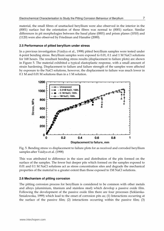
In a previous investigation (Vaidya et al., 1998) pitted beryllium samples were tested under 4-point bending stress. Beryllium samples were exposed to 0.01, 0.1 and 1 M NaCl solutions for 168 hours. The resultant bending stress results (displacement to failure plots) are shown in Figure 5. The material exhibited a typical elastoplastic response, with a small amount of strain hardening. Displacement to failure and failure strength of the samples were affected by exposure to the NaCl solutions, however, the displacement to failure was much lower in 0.1 M and 0.01 M solutions than in a 1 M solution.
Fig. 5. Bending stress vs displacement to failure plots for as received and corroded beryllium samples after Vaidya et al. (1998)
This was attributed to difference in the sizes and distribution of the pits formed on the surface of the samples. The fewer but deeper pits which formed on the samples exposed to 0.01 and 0.1 M NaCl solutions act as stress concentration sites and degrade the mechanical properties of the material to a greater extent than those exposed to 1M NaCl solutions.
2.6 Mechanism of pitting corrosion
The pitting corrosion process for beryllium is considered to be common with other metals
and alloys (aluminium, titanium and stainless steel) which develop a passive oxide film.
Following the development of the passive oxide film there are four processes (Szklarska-
Smialowska, 1999) which lead to the onset of corrosion pits as; (1) Interactions occurring at
the surface of the passive film; (2) interactions occurring within the passive film; (3)
www.intechopen.com
Pitting Corrosion
8
formation of metastable pits which soon repassivate; and (4) stable pit growth, above certain
potential termed the critical pitting potential.
The first two stages are concerned with the breakdown of film by the interaction of chloride
ions, with very little being known about the interaction mechanism. This is certainly
dependent upon the composition and structure of the oxide film and the underlying
material. The structural characteristics of the oxide are dependent on the material
composition and hence the presence and distribution of micro-defects (vacancies, voids, etc.)
as well as macro-defects (inclusions, second phase particles and their size and shape), crystal
structure and the degree of noncrytalinity of the oxide. It also depends on the electrolyte, its
composition, pH value and temperature (Szklarska-Smialowska, 1999).
Metastable pits form sometimes just before the pitting potential is reached. When these
occur first the current increases as the pit nucleate and grow, then decreasing after a short
delay. It was found that metastable pits are covered by a remnant hard oxide film. It is well
established that metastable pits sometimes form several hundred milli volts below the
pitting potential and during the induction time for stable pit formation. There are a number
of studies for metastable pits on steel and aluminium (Blanc & Mankowski, 1997; Pride et
al., 1994) but few on beryllium (Lillard, 2000).
According to a previously suggested mechanism (West, 1970) a filmed metal may begin to
dissolve at sensitive points. These sensitive points may be crystallographic defects, cavities
or scratches in metal, or a rift in surface film due to high internal stresses during oxide
growth. Some of these sensitive points are associated with the localised chemical
deficiencies in the film where there are underlying inclusions. As the dissolution proceeds at
localised points where the film is impaired, the remaining intact surface film acts as a
cathodic area. At this stage, two other important processes are taking place inside the pore
(a shallow pit). Firstly the attempt by the film to repair itself at the pore consumes hydroxyl
ions so the acidity within the pore is increased. Secondly the pore being an anodic site,
causes various aggressive ions such as Cl-1 to accumulate within the pore. Being highly
deformable, chloride ions are surface active, so they displace water molecules from the
double layer. The film in the pore therefore is prevented from repairing itself. At the same
time, depletion of aggressive ions from the immediate vicinity of the pore makes it more
difficult for the anodic reaction to spread sideways. This action together with a large surface
area acting as cathode makes an accelerated dissolution at the localised area of pore, thus
promoting it to become a narrow deep pit.
3. Investigation on the effect of inclusions on pitting corrosion behaviour of beryllium
3.1 Introduction
Mueller & Adolphson concluded that pitting corrosion is associated with beryllium carbide
particles. Carbon arises as one of the primary impurities in historic grades of beryllium to
0.2 wt% or more, which results in formation of second-phase particles (Be2C). In the
presence of moisture these particles quickly react to form BeO and methane.
Be2C + 2 H2O → 2 BeO + CH4 (5)
www.intechopen.com
Electrochemical Characterisation to Study the Pitting Corrosion Behaviour of Beryllium
9
It may be noted that once carbide particles have been consumed no further corrosion should be observed. However, in the presence of corrosive ions in moist environments the above corrosion reaction may disrupt the continuity of the passivating film and provide a crevice site for further reaction.
Earlier studies (Gulbrandsen & Johansen, 1994; Venugopal et al., 2000) have indicated that corrosion pits in beryllium may be associated with sites previously occupied by inclusions. Beryllium components for structural applications are generally produced by a powder metallurgy route and contain a number of impurities as a result of the powder production process, from which the pressed component is manufactured, and as a result of the powder pressing process itself. The major impurities found in such structural material include, beryllium oxide (> 0.5 wt. %), carbides (carbon up to 0.015 wt. %), silicon (~ 0.025 wt. %), and the intermetallic compounds.
The purpose of the study at AWE was to understand the role these inclusions play in the initiation of localised corrosion attack. To accomplish this, the electrochemical characteristics of beryllium material containing differing impurity contents and distribution were assessed and the resulting localised corrosion sites evaluated. Earlier results of this investigation were published in a previous paper (Punni & Cox, 2010) and a brief account of this work with updated information is described here.
3.2 Experimental procedure
3.2.1 Material
Samples measuring 12.5 mm in diameter and 2 mm thick were machined from three different beryllium pressings, i.e. a small vacuum hot pressed bar produced from Brush Wellman S65 specification power (S65-Bar), a large vacuum hot pressed billet also produced from S65 specification power (S65-Billet), and a small vacuum hot pressed bar produced from Kawecki Berylco P10 specification powder (P10-Bar). All pressings had been consolidated using graphite dies under a pressure of ~7 MN/m2 and at a temperature of 1000 to 1100 ºC, followed by a heat treatment at 800 ºC. The metallic impurity content for each pressing was determined by Emission Spectroscopy via Direct Coupled Plasma, BeO by Inert Gas Fusion (LECO method), and carbon by combustion (LECO method). The chemical composition of these grades is given in Table 1.
3.2.2 SEM examination and pit initiation treatment
To understand the pit initiation sites it is important to know the microstructure for all the
three beryllium grades. For this task, samples were progressively polished down to 0.25 µm
diamond finish. Polished samples were examined in a Hitachi SEM with the impurity
inclusions being analysed using the associated EDS system (Oxford Instruments). Secondary
electron (SE) images and EDS spectra showing elemental analysis were recorded.
For pit initiation treatment the same polished samples were subjected to an electrochemical
polarisation treatment to initiate tiny corrosion pits at the polished surface. This was done in
0.001 M KCl solution at a fast sweep rate of 600 mV/min. Polarisation started at -1100 mV
SCE and ended at -500 mV SCE and the time during which the sample stayed in the pitting
range (-800mV SCE to -500mV SCE) was ~30 seconds; referred to as the exposure time for
www.intechopen.com

Pitting Corrosion
10
pit initiation treatment. After the pit initiation treatment the samples were rinsed in distilled
water and wiped with ethanol soaked tissues. Samples were then examined again in the
Hitachi SEM to locate any pit initiation sites and to perform elemental analysis on those sites.
Element/Compound S65-Bar S65-Billet P10-Bar Uncertainty of Measurements
Be 99.3 99.23 98.46 Balance
BeO 0.56 0.6 1.18 ± 0.04
C 0.03 0.015 0.08 ± 0.009
Si 0.025 0.028 0.028 ±0.0024
Al 0.02 0.033 0.045 ± 0.0020
Fe 0.056 0.075 0.133 ±0.0032
Mg 0.0005 <0.0005 0.013 ± 0.0023
U 0.004 <0.0030 0.027 ± 0.0043
Co 0.001 0.0007 0.0012 ± 0.0003
Cr 0.0025 0.0025 0.0135 ± 0.0005
Cu 0.0025 0.0065 0.007 ± 0.00016
Ti 0.0045 0.011 0.011 ± 0.0003
Table 1. The compositions (wt %) of three different beryllium specifications studied in this investigation
3.2.3 Polarisation technique
This technique is described in greater detail in a previous investigation (Punni & Cox, 2010).
Samples for polarisation tests were ground down to a 600 grit silicon carbide paper finish. A
custom designed glass electrochemical cell, equipped with a platinum counter electrode,
noise electrode and a saturated calomel reference electrode (SCE) through a Luggin probe,
was used in this study.
The potentiodynamic polarisation tests were carried out at room temperature (20 ± 2 ºC) at a sweep rate of 20 mV/min using a Gill AC Potentiostat. Some polarisation tests were carried out at a sweep rate of 10 mV/min. Tests were performed in a deaerated 600 ml potassium chloride (KCl) solution of 0.0001, 0.001, 0.01 or 0.1 M chloride concentrations with pH adjusted to 7, by adding a few drops of dilute potassium hydroxide solution. To ensure dynamic equilibrium, samples were left at their open circuit potential for 1 hour before each polarisation test was run. Some electrochemically polarised samples were also examined in a Hitachi SEM model S3400N to characterise the extent and nature of the corrosion pits.
3.3 Results and discussion
3.3.1 Microstructures of the three beryllium grades
SEM examination revealed that inclusions, varying in size and composition, were situated at the grain boundaries, as summarised in Table 2.
www.intechopen.com
Electrochemical Characterisation to Study the Pitting Corrosion Behaviour of Beryllium
11
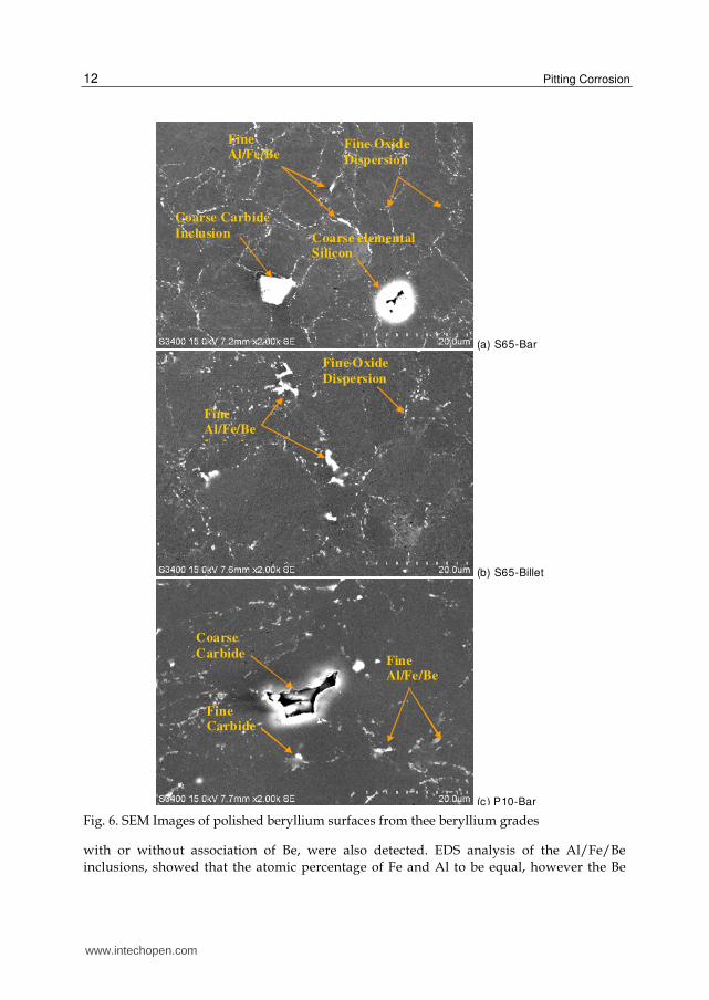
Coarse Inclusions: All beryllium grades showed some coarse inclusions, 5 to 18 µm in
diameter. The population and size of these coarse inclusions were greater in P10-Bar than in
the other two grades. These coarse inclusions along with the fine inclusions (< 5 µm in size)
can be seen in SEM images shown in Figures 6 (a to c). Most of the coarse inclusions
appeared to be partially broken or dissolved by the abrading and polishing operations. The
EDS analysis identified the coarse inclusions to be mainly elemental silicon, and mixed
beryllium carbides containing Al, Si, Fe and occasionally other elements such as Ti, Mg, Cr
and U (Table 2).
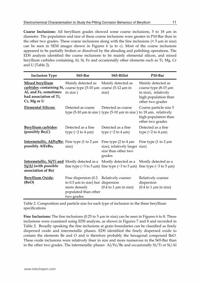
Inclusion Type S65-Bar S65-Billet P10-Bar
Mixed beryllium carbides: containing Si, Al, and Fe, sometimes had association of Ti, Cr, Mg or U
Mainly detected as coarse type (5-10 µm in size )
Mainly detected as coarse (5-12 µm in size)
Mainly detected as coarse type (8-15 µm in size), relatively high population than other two grades
Elemental Silicon: Detected as coarse type (5-10 µm in size )
Detected as coarse type (5-10 µm in size )
Coarse particle size 5 to 18 µm, relatively high population than other two grades
Beryllium carbides: (possibly Be2C)
Detected as a fine type (~2 to 4 µm)
Detected as a fine type (~2 to 4 µm)
Detected as a fine type (~2 to 4 µm)
Intermetallic, Al/Fe/Be: possibly AlFeBe4
Fine type (1 to 2 µm size)
Fine type (2 to 4 µm size), relatively larger size than other two grades
Fine type (1 to 2 µm size)
Intermetallic, Si/Ti and Si/Al (with possible association of Be)
Mostly detected as a fine type (~3 to 5 µm)
Mostly detected as a fine type (~3 to 5 µm)
Mostly detected as a fine type (~3 to 5 µm)
Beryllium Oxide: (BeO)
Fine dispersion (0.2 to 0.5 µm in size) but more densely populated than other two grades
Relatively coarser dispersion (0.4 to 1 µm in size)
Relatively coarser dispersion (0.4 to 1 µm in size)
Table 2. Composition and particle size for each type of inclusion in the three beryllium specifications
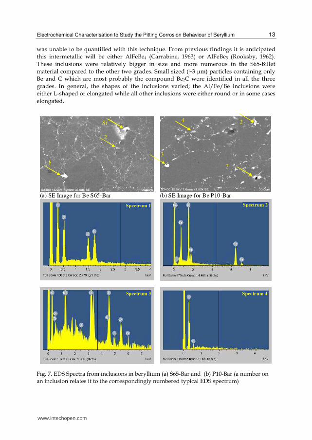
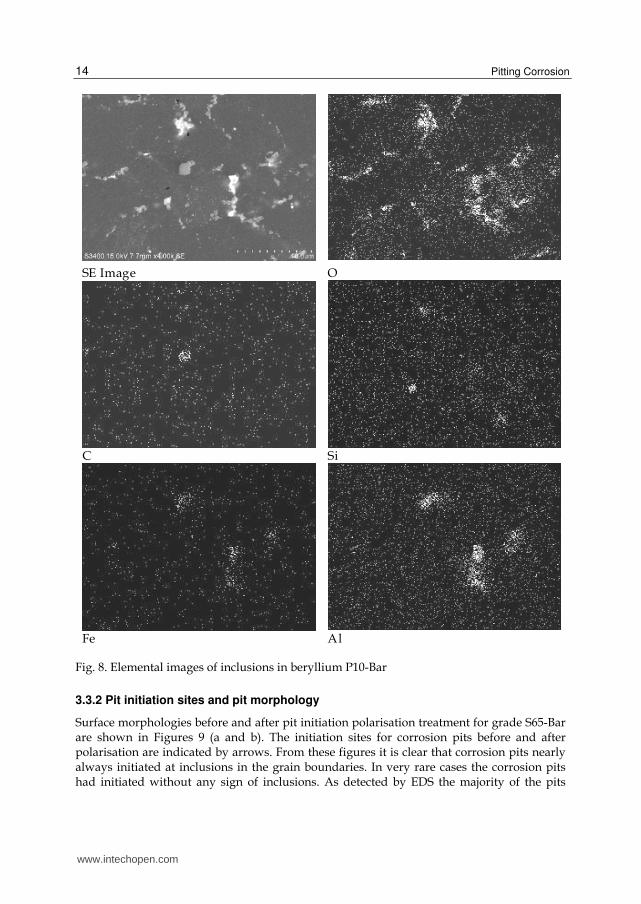
Fine Inclusions: The fine inclusions (0.25 to 5 µm in size) can be seen in Figures 6 to 8. These
inclusions were examined using EDS analysis, as shown in Figures 7 and 8 and recorded in
Table 2. Broadly speaking the fine inclusions at grain boundaries can be classified as finely
dispersed oxide and intermetallic phases. EDS identified the finely dispersed oxide to
contain the elements Be and O and is therefore probably the hexagonal compound BeO.
These oxide inclusions were relatively finer in size and more numerous in the S65-Bar than
in the other two grades. The intermetallic phases Al/Fe/Be and occasionally Si/Ti or Si/Al
www.intechopen.com
Pitting Corrosion
12
Fig. 6. SEM Images of polished beryllium surfaces from thee beryllium grades
with or without association of Be, were also detected. EDS analysis of the Al/Fe/Be
inclusions, showed that the atomic percentage of Fe and Al to be equal, however the Be
(a) S65-Bar
(b) S65-Billet
(c) P10-Bar
Coarse
Carbide
Coarse Carbide
Inclusion Coarse elemental Silicon
Fine Carbide
Fine Al/Fe/Be
I l i
Fine Oxide
Dispersion
Fine Al/Fe/Be
Fine Al/Fe/Be
Fine Oxide
Dispersion
www.intechopen.com
Electrochemical Characterisation to Study the Pitting Corrosion Behaviour of Beryllium
13
was unable to be quantified with this technique. From previous findings it is anticipated
this intermetallic will be either AlFeBe4 (Carrabine, 1963) or AlFeBe5 (Rooksby, 1962).
These inclusions were relatively bigger in size and more numerous in the S65-Billet
material compared to the other two grades. Small sized (~3 µm) particles containing only
Be and C which are most probably the compound Be2C were identified in all the three
grades. In general, the shapes of the inclusions varied; the Al/Fe/Be inclusions were
either L-shaped or elongated while all other inclusions were either round or in some cases
elongated.
Fig. 7. EDS Spectra from inclusions in beryllium (a) S65-Bar and (b) P10-Bar (a number on an inclusion relates it to the correspondingly numbered typical EDS spectrum)
(a) SE Image for Be S65-Bar (b) SE Image for Be P10-Bar
Si
2
1
3
2 4
2
Spectrum 1 Spectrum 2
Spectrum 3 Spectrum 4
www.intechopen.com
Pitting Corrosion
14
Fig. 8. Elemental images of inclusions in beryllium P10-Bar
3.3.2 Pit initiation sites and pit morphology
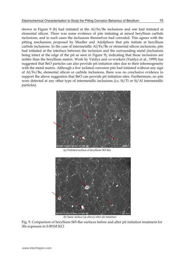
Surface morphologies before and after pit initiation polarisation treatment for grade S65-Bar are shown in Figures 9 (a and b). The initiation sites for corrosion pits before and after polarisation are indicated by arrows. From these figures it is clear that corrosion pits nearly always initiated at inclusions in the grain boundaries. In very rare cases the corrosion pits had initiated without any sign of inclusions. As detected by EDS the majority of the pits
SE Image O
C Si
Fe Al
www.intechopen.com
Electrochemical Characterisation to Study the Pitting Corrosion Behaviour of Beryllium
15
shown in Figure 9 (b) had initiated at the Al/Fe/Be inclusions and one had initiated at elemental silicon. There was some evidence of pits initiating at mixed beryllium carbide inclusions, and in such cases the inclusions themselves had corroded. This agrees with the pitting mechanism proposed by Mueller and Adolphson that pits initiate at beryllium carbide inclusions. In the case of intermetallic Al/Fe/Be or elemental silicon inclusions, pits had initiated at the interface between the inclusion and the surrounding metal (inclusions being intact at the edge of the pit as seen in Figure 9), indicating that these inclusions are nobler than the beryllium matrix. Work by Vaidya and co-workers (Vaidya et al., 1999) has suggested that BeO particles can also provide pit initiation sites due to their inhomogeneity with the metal matrix. Although a few isolated corrosion pits had initiated without any sign of Al/Fe/Be, elemental silicon or carbide inclusions, there was no conclusive evidence to support the above suggestion that BeO can provide pit initiation sites. Furthermore, no pits were detected at any other type of intermetallic inclusions (i.e. Si/Ti or Si/Al intermetallic particles).
Fig. 9. Comparison of beryllium S65-Bar surfaces before and after pit initiation treatment for 30s exposure in 0.001M KCl
.
(a) Polished surface of beryllium S65-Bar
(b) Same surface (as above) after pit initiation
www.intechopen.com
Pitting Corrosion
16
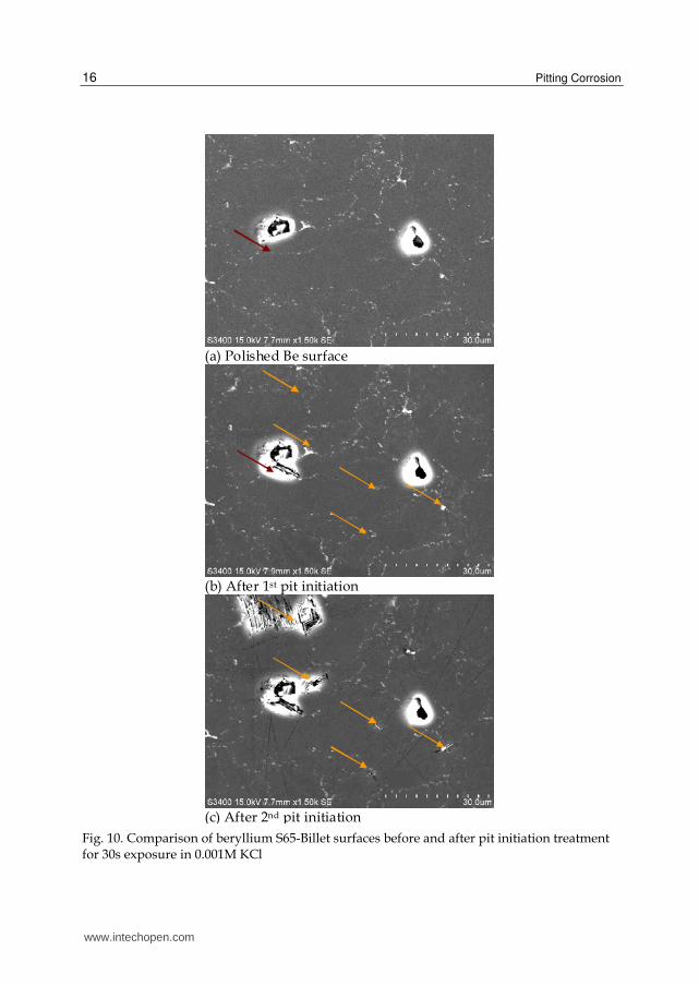
Fig. 10. Comparison of beryllium S65-Billet surfaces before and after pit initiation treatment for 30s exposure in 0.001M KCl
(a) Polished Be surface
(b) After 1st pit initiation
(c) After 2nd pit initiation
www.intechopen.com
Electrochemical Characterisation to Study the Pitting Corrosion Behaviour of Beryllium
17
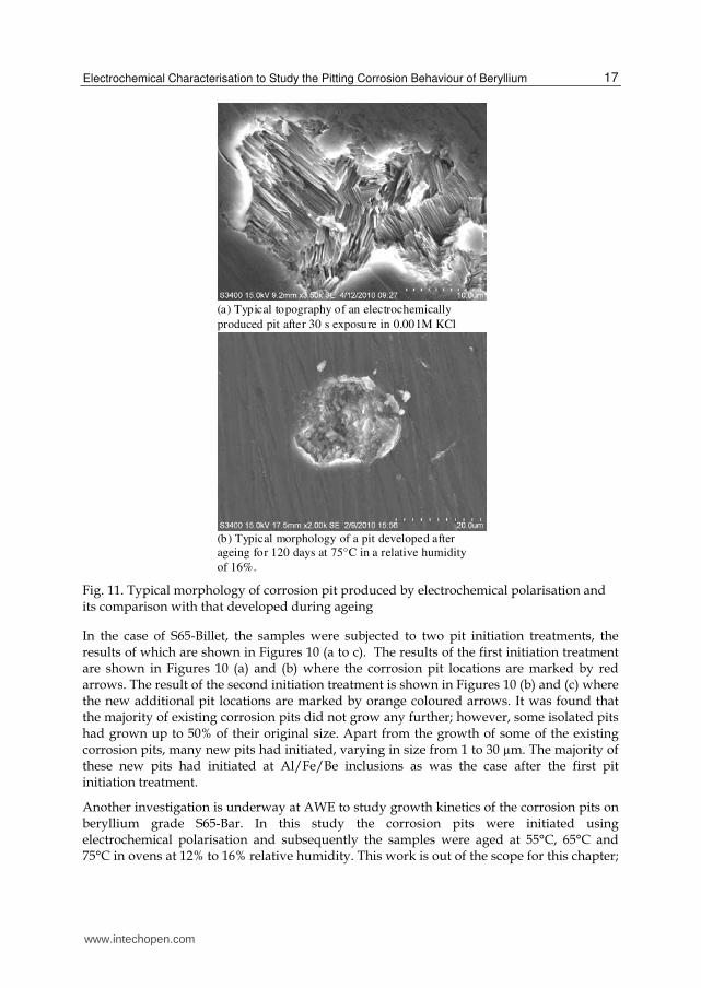
Fig. 11. Typical morphology of corrosion pit produced by electrochemical polarisation and its comparison with that developed during ageing
In the case of S65-Billet, the samples were subjected to two pit initiation treatments, the results of which are shown in Figures 10 (a to c). The results of the first initiation treatment are shown in Figures 10 (a) and (b) where the corrosion pit locations are marked by red arrows. The result of the second initiation treatment is shown in Figures 10 (b) and (c) where the new additional pit locations are marked by orange coloured arrows. It was found that the majority of existing corrosion pits did not grow any further; however, some isolated pits had grown up to 50% of their original size. Apart from the growth of some of the existing corrosion pits, many new pits had initiated, varying in size from 1 to 30 µm. The majority of these new pits had initiated at Al/Fe/Be inclusions as was the case after the first pit initiation treatment.
Another investigation is underway at AWE to study growth kinetics of the corrosion pits on beryllium grade S65-Bar. In this study the corrosion pits were initiated using electrochemical polarisation and subsequently the samples were aged at 55°C, 65°C and 75°C in ovens at 12% to 16% relative humidity. This work is out of the scope for this chapter;
(a) Typical topography of an electrochemically
produced pit after 30 s exposure in 0.001M KCl
(b) Typical morphology of a pit developed after
ageing for 120 days at 75°C in a relative humidity
of 16%.
www.intechopen.com
Pitting Corrosion
18
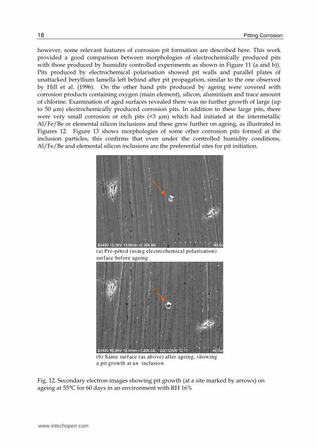
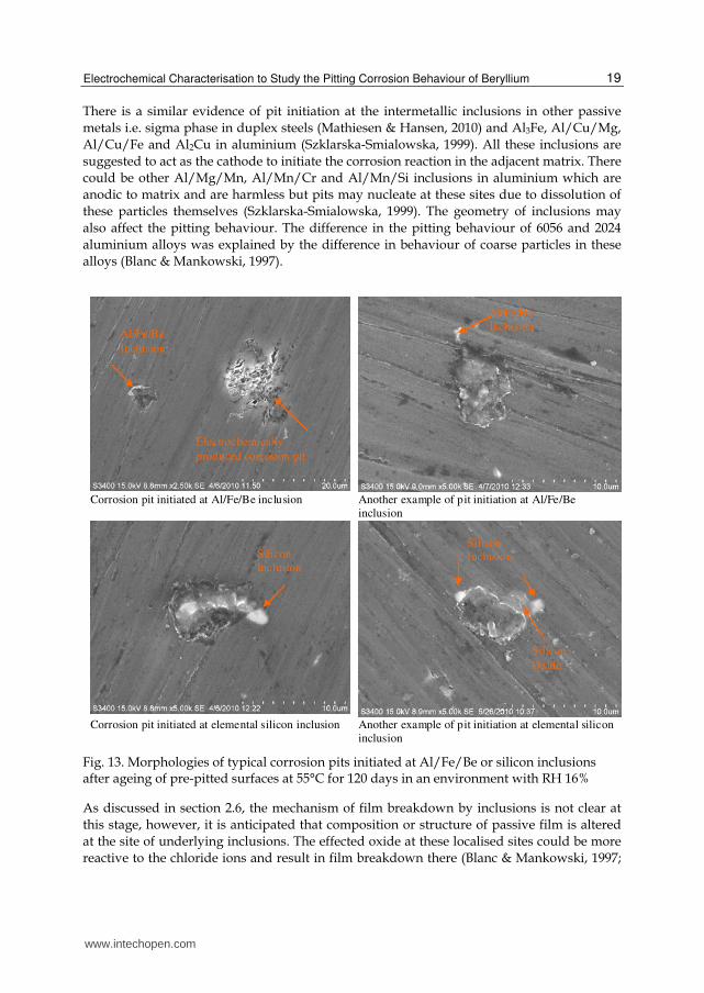
however, some relevant features of corrosion pit formation are described here. This work provided a good comparison between morphologies of electrochemically produced pits with those produced by humidity controlled experiments as shown in Figure 11 (a and b)). Pits produced by electrochemical polarisation showed pit walls and parallel plates of unattacked beryllium lamella left behind after pit propagation, similar to the one observed by Hill et al. (1996). On the other hand pits produced by ageing were covered with corrosion products containing oxygen (main element), silicon, aluminium and trace amount of chlorine. Examination of aged surfaces revealed there was no further growth of large (up to 50 µm) electrochemically produced corrosion pits. In addition to these large pits, there were very small corrosion or etch pits (<3 µm) which had initiated at the intermetallic Al/Fe/Be or elemental silicon inclusions and these grew further on ageing, as illustrated in Figures 12. Figure 13 shows morphologies of some other corrosion pits formed at the inclusion particles, this confirms that even under the controlled humidity conditions, Al/Fe/Be and elemental silicon inclusions are the preferential sites for pit initiation.
Fig. 12. Secondary electron images showing pit growth (at a site marked by arrows) on ageing at 55°C for 60 days in an environment with RH 16%
(a) Pre-pitted (using electrochemical polarisation)
surface before ageing
(b) Same surface (as above) after ageing, showing
a pit growth at an inclusion
www.intechopen.com
Electrochemical Characterisation to Study the Pitting Corrosion Behaviour of Beryllium
19
There is a similar evidence of pit initiation at the intermetallic inclusions in other passive
metals i.e. sigma phase in duplex steels (Mathiesen & Hansen, 2010) and Al3Fe, Al/Cu/Mg,
Al/Cu/Fe and Al2Cu in aluminium (Szklarska-Smialowska, 1999). All these inclusions are
suggested to act as the cathode to initiate the corrosion reaction in the adjacent matrix. There
could be other Al/Mg/Mn, Al/Mn/Cr and Al/Mn/Si inclusions in aluminium which are
anodic to matrix and are harmless but pits may nucleate at these sites due to dissolution of
these particles themselves (Szklarska-Smialowska, 1999). The geometry of inclusions may
also affect the pitting behaviour. The difference in the pitting behaviour of 6056 and 2024
aluminium alloys was explained by the difference in behaviour of coarse particles in these
alloys (Blanc & Mankowski, 1997).
Fig. 13. Morphologies of typical corrosion pits initiated at Al/Fe/Be or silicon inclusions after ageing of pre-pitted surfaces at 55°C for 120 days in an environment with RH 16%
As discussed in section 2.6, the mechanism of film breakdown by inclusions is not clear at
this stage, however, it is anticipated that composition or structure of passive film is altered
at the site of underlying inclusions. The effected oxide at these localised sites could be more
reactive to the chloride ions and result in film breakdown there (Blanc & Mankowski, 1997;
Corrosion pit initiated at Al/Fe/Be inclusion Another example of pit initiation at Al/Fe/Be
inclusion
Corrosion pit initiated at elemental silicon inclusion Another example of pit initiation at elemental silicon
inclusion
Al/Fe/Be
Inclusion
Al/Fe/Be
Inclusion
Electrochemically
produced corrosion pit
Silicon
Inclusion
Silicon
Inclusion
Silicon
Oxide
www.intechopen.com
Pitting Corrosion
20
West 1970). It is also evident from this investigation that certain inclusions cause galvanic
action with the matrix to initiate pitting, as the corrosion pit sites had the presence of
intermetallic Al/Fe/Be and elemental silicon inclusions (Figure 13) suggesting that these act
as cathode to promote corrosion of the surrounding metal . Other inclusions like carbides or
any less noble inclusions may also result in pit initiation by dissolving themselves
preferentially to the matrix.
3.3.3 Electrochemical polarisation of the three beryllium grades
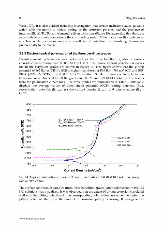
Potentiodynamic polarisation was performed for the three beryllium grades in various chloride concentrations, from 0.0001 M to 0.1 M KCl solutions. Typical polarisation curves for all the beryllium grades are shown in Figure 14. This figure shows that the pitting potential of S65-Bar at -745mV SCE is higher than those for P10-Bar (-790 mV SCE) and S65-Billet (-765 mV SCE) in a 0.0001 M KCl solution. Similar differences in polarisation behaviour were observed for all the grades in 0.001M and 0.01 M KCl solution. The results from the polarisation curves for all the three grades are summarised in Table 3. This table displays the average values of open circuit potential (OCP), pitting potential (Epit), repassivation potential (Erepass), passive current density (ipassive) and passive range (Epit - OCP).
Fig. 14. Typical polarisation curves for 3 beryllium grades in 0.0001M KCl solution, sweep rate of 20mV/min
The surface condition of samples (from three beryllium grades) after polarisation in 0.001M KCl solutions was visualised. It was observed that the extent of pitting corrosion correlated well with the pitting potentials in the corresponding polarisation curves i.e. the higher the pitting potential, the lower the amount of corrosion pitting occurring. It was generally
-1150
-1100
-1050
-1000
-950
-900
-850
-800
-750
-700
-650
-600
0 0 0 0 0 0 0Current Density (mA/cm
2)
Po
ten
tial
(mV
, S
CE
)
S38, S65-Bar
S79, P10-Bar
S97, S65-Billet
Epit (S65-Bar)=-745mV
Epit (P10-Bar)=-790mV
Epit (S65-Billet)=-765mV
10-7
10-6
10-5
10-4
10-3
10-2
10-1
www.intechopen.com
Electrochemical Characterisation to Study the Pitting Corrosion Behaviour of Beryllium
21
observed that polarisation at the slower sweep rate results in a denser population of corrosion pits.
Solution Beryllium Specification
Open Circuit Potential, mV SCE
Pitting Potential, mV SCE
Repassivation Potential, mV
SCE
Passive Current Density, µA/cm2
Passive Range,
mV
0.0001M KCl
S65-Bar
-1068 ± 67 -750 ± 7 -802 ± 10 0.51 ± 0.08 318
S65-Billet
-1032 ± 22 -754 ± 16 -811 ± 17 0.46 ± 0.16 278
P10-Bar
-1033 ±81 -773 ± 25 -831 ± 1 0.34 ± 0.03 260
0.001M KCl
S65-Bar
-974 ± 66 -816 ± 21 -922 ± 26 0.31 ± 0.21 158
S65-Billet
-934 ± 30 -835 ± 22 -926 ± 22 0.38 ± 0.22 99
P10-Bar
-937 ± 17 -838 ± 25 -930 ± 16 0.28 ±0.20 99
0.01M KCL
S65-Bar
-1029 ± 36 -898 ± 21 -977 ± 7 0.36 ± 0.25 131
S65-Billet
-1028 ± 17 -919 ± 2 -975 ± 9 0.40 ± 0.14 109
P10-Bar
-1020 ± 28 -909 ±16 -962 ± 11 0.34 ± 0.11 111
0.1M KCl S65-Bar
-1022 ± 42 -978 ± 4 -1000 ± 4 0.69 ± 0.35 44
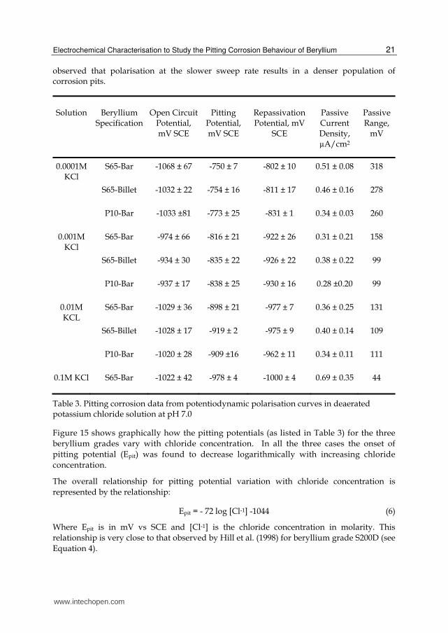
Table 3. Pitting corrosion data from potentiodynamic polarisation curves in deaerated potassium chloride solution at pH 7.0
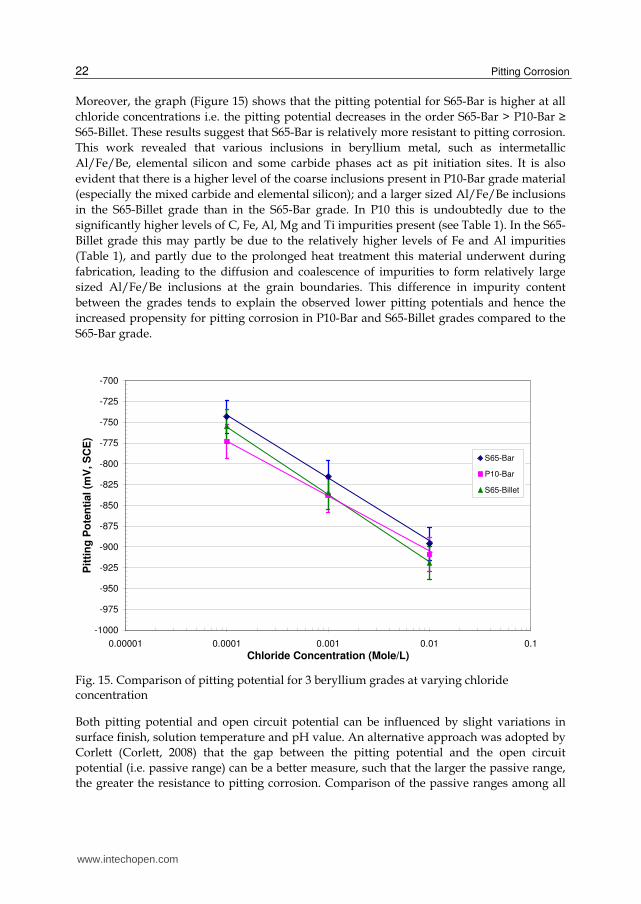
Figure 15 shows graphically how the pitting potentials (as listed in Table 3) for the three
beryllium grades vary with chloride concentration. In all the three cases the onset of
pitting potential (Epit) was found to decrease logarithmically with increasing chloride
concentration.
The overall relationship for pitting potential variation with chloride concentration is
represented by the relationship:
Epit = - 72 log [Cl-1] -1044 (6)
Where Epit is in mV vs SCE and [Cl-1] is the chloride concentration in molarity. This
relationship is very close to that observed by Hill et al. (1998) for beryllium grade S200D (see
Equation 4).
www.intechopen.com
Pitting Corrosion
22
Moreover, the graph (Figure 15) shows that the pitting potential for S65-Bar is higher at all
chloride concentrations i.e. the pitting potential decreases in the order S65-Bar > P10-Bar ≥
S65-Billet. These results suggest that S65-Bar is relatively more resistant to pitting corrosion.
This work revealed that various inclusions in beryllium metal, such as intermetallic
Al/Fe/Be, elemental silicon and some carbide phases act as pit initiation sites. It is also
evident that there is a higher level of the coarse inclusions present in P10-Bar grade material
(especially the mixed carbide and elemental silicon); and a larger sized Al/Fe/Be inclusions
in the S65-Billet grade than in the S65-Bar grade. In P10 this is undoubtedly due to the
significantly higher levels of C, Fe, Al, Mg and Ti impurities present (see Table 1). In the S65-
Billet grade this may partly be due to the relatively higher levels of Fe and Al impurities
(Table 1), and partly due to the prolonged heat treatment this material underwent during
fabrication, leading to the diffusion and coalescence of impurities to form relatively large
sized Al/Fe/Be inclusions at the grain boundaries. This difference in impurity content
between the grades tends to explain the observed lower pitting potentials and hence the
increased propensity for pitting corrosion in P10-Bar and S65-Billet grades compared to the
S65-Bar grade.
Fig. 15. Comparison of pitting potential for 3 beryllium grades at varying chloride concentration
Both pitting potential and open circuit potential can be influenced by slight variations in
surface finish, solution temperature and pH value. An alternative approach was adopted by
Corlett (Corlett, 2008) that the gap between the pitting potential and the open circuit
potential (i.e. passive range) can be a better measure, such that the larger the passive range,
the greater the resistance to pitting corrosion. Comparison of the passive ranges among all
-1000
-975
-950
-925
-900
-875
-850
-825
-800
-775
-750
-725
-700
0.00001 0.0001 0.001 0.01 0.1
Chloride Concentration (Mole/L)
Pit
tin
g P
ote
nti
al (m
V, S
CE
)
S65-Bar
P10-Bar
S65-Billet
www.intechopen.com
Electrochemical Characterisation to Study the Pitting Corrosion Behaviour of Beryllium
23
the three grades (as listed in Table 3) at various chloride concentrations also confirms that
S65-Bar is more resistant to pitting corrosion than the other two grades.
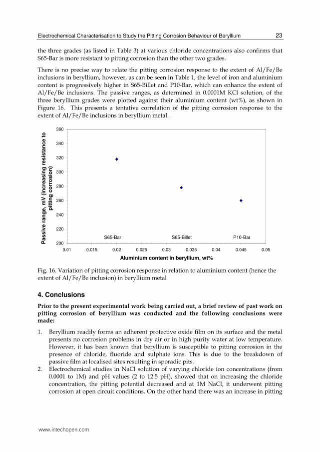
There is no precise way to relate the pitting corrosion response to the extent of Al/Fe/Be
inclusions in beryllium, however, as can be seen in Table 1, the level of iron and aluminium
content is progressively higher in S65-Billet and P10-Bar, which can enhance the extent of
Al/Fe/Be inclusions. The passive ranges, as determined in 0.0001M KCl solution, of the
three beryllium grades were plotted against their aluminium content (wt%), as shown in
Figure 16. This presents a tentative correlation of the pitting corrosion response to the
extent of Al/Fe/Be inclusions in beryllium metal.
Fig. 16. Variation of pitting corrosion response in relation to aluminium content (hence the extent of Al/Fe/Be inclusion) in beryllium metal
4. Conclusions
Prior to the present experimental work being carried out, a brief review of past work on pitting corrosion of beryllium was conducted and the following conclusions were made:
1. Beryllium readily forms an adherent protective oxide film on its surface and the metal presents no corrosion problems in dry air or in high purity water at low temperature. However, it has been known that beryllium is susceptible to pitting corrosion in the presence of chloride, fluoride and sulphate ions. This is due to the breakdown of passive film at localised sites resulting in sporadic pits.
2. Electrochemical studies in NaCl solution of varying chloride ion concentrations (from 0.0001 to 1M) and pH values (2 to 12.5 pH), showed that on increasing the chloride concentration, the pitting potential decreased and at 1M NaCl, it underwent pitting corrosion at open circuit conditions. On the other hand there was an increase in pitting
200
220
240
260
280
300
320
340
360
0.01 0.015 0.02 0.025 0.03 0.035 0.04 0.045 0.05
Aluminium content in beryllium, wt%
Pas
siv
e r
an
ge
, m
V (
inc
rea
sin
g r
es
ista
nc
e t
o
pit
tin
g c
orr
osio
n)
S65-Bar S65-Billet P10-Bar
www.intechopen.com
Pitting Corrosion
24
potential with increase in pH. Beryllium was found to be suffering from pitting corrosion in the pH range from 2 to 12.5 but was susceptible to general attack below a pH of 2.
3. Pitting experiments on single crystals have indicated that beryllium corrodes preferentially along certain orientations. The pitting potential, Epit, was found to
decrease with surface orientation in the order (0001) > (1010) > (1120). In polycrystalline beryllium there was no correlation between pit initiation sites and crystallographic orientation of specific grains. Therefore, altering the bulk texture of polycrystalline beryllium will not affect the pitting corrosion resistance of beryllium, although it may affect pit propagation
4. A relationship has been observed between failure strength and chloride ion concentration in terms of the type of corrosion pits generated in beryllium. Fewer but deeper pits degrade the mechanical properties of the material to a greater extent than that by numerous but shallower pits.
5. Previously suggested mechanisms for pitting corrosion have been reviewed.
The present experimental work was aimed at determining the effect of inclusions on pitting corrosion behaviour of beryllium. The following conclusions were drawn:
6. SEM examination of the polished samples of the three beryllium grades showed that there was a presence of fine inclusion particles (0.25 to 5 µm) and some relatively coarse particles (5 to 18 µm) located along the grain boundaries. In all cases, the majority of the fine inclusions were identified as BeO and intermetallic phases such as Al/Fe/Be (and in a few cases Si/Ti or Si/Al). The coarse inclusions were elemental silicon and mixed beryllium carbides. Other elements such as Mg, Ti, U and Cr were also associated with some intermetallic and mixed carbide phases.
7. SEM examination revealed that the number of coarse inclusions (and hence the overall inclusion population) was much greater in P10-Bar than that in the other two grades. In the case of S65-billet, although the overall inclusion content was approximately the same as in the S65-bar, the intermetallic Al/Fe/Be inclusion content was much higher (i.e. larger particle size).
8. From the pit initiation study (using both electrochemical and ageing techniques), it was observed that corrosion pits were nearly always initiated at the metal grain boundaries. Although the intermetallic Al/Fe/Be and elemental silicon inclusions were the preferential sites for pit initiation, some corrosion pits had also initiated at carbide inclusions.
9. Electrochemical polarisation of the three beryllium grades showed that the pitting potential of S65-Bar grade was relatively high compared to the other two grades. This is in agreement with the extent of corrosion pitting revealed on the coupons after polarisation.
10. The nature and extent of inclusions in each grade showed a strong relationship with its pitting potential. The lower overall inclusion content of the S65-Bar compared to the P10-Bar, and its lower Al/Fe/Be intermetallic inclusion content compared to the S65-Billet, resulted in it displaying a corresponding higher pitting potential and hence a relatively greater resistance to pitting corrosion.
11. It is evident from the present work that the various inclusions in beryllium located at the grain boundaries, such as Al/Fe/Be, elemental silicon and carbides act as pit initiation sites and hence their presence is likely to enhance the propensity for pitting corrosion.
www.intechopen.com
Electrochemical Characterisation to Study the Pitting Corrosion Behaviour of Beryllium
25
5. Acknowledgements
The author would like to thank Ms. Jennifer Copeland of Brush Wellman Industries for the chemical analysis. The author also wish to acknowledge Mr Mike Cox, Dr Andrew Wallwork and Dr S McCulloch of AWE for their support.
6. References
Blanc, C. & Mankowski, G. (1997). Susceptibility to Pitting Corrosion of 6056 Aluminium alloy, Corrosion Science, vol. 39, 1997, pp. 949-959
Carrabine, J. A. (1963). Ternary AlMBe4 Phases in Commercially Pure Beryllium, J. Nuclear Materials, Vol. 8, pp. 278-280.
Corlett, N. (2008). Corrosion Checking, Materials World 2008, Vol. 16, pp. 27-29 Friedman, J. R. & Hanafee, J. E. (2000). Corrosion/Electrochemistry of Monocrystalline and
Polycrystalline Beryllium in Aqueous Chloride Environment, UCRL-ID-137482 Flitton, M. K. A.; Mizia, R. E. & Bishop, C. W. (2002) Understanding Corrosion of Activated
Metals in an Arid Vadose Zone Environment, INEEL/CON-01-01450, NACE Gulbrandsen, E. & Johansen, A. M. J. (1994), A Study of the Passive Behaviour of Beryllium
in Aqueous Solutions, Corrosion Science, Vol. 36, pp. 1523-1536 Hill, M. A.; Butt, D. P. & Lillard, R. S. (1996). The Corrosion/Electrochemistry of Beryllium
and Beryllium Weldments in Aqueous Chloride Environments, Los Alamos National Laboratory New Mexico, Internet Report No. 87545.
Hill, M. A.; Butt, D. P. & Lillard, R. S. (1998). The Passivity and Breakdown of Beryllium in Aqueous Solutions, J. Electrochemical Soc., Vol. 145, pp. 2799-2806
Kaye, G. W. C. & Laby T. H. (1978). Tables of Physicals and Chemical Constants, Longman Press, New York 1978, p. 216
Lillard, R. S. (2000). Factors Influencing the Transition from Metastable to Stable Pitting in Single-Crystal Beryllium, J. Electrochemical Soc., Vol. 148, pp. B1-B11
Miller, P.D. & Boyd, W. K. (1968). Beryllium Deters Corrosion- some do’s and don’ts, Materials Engineering (July 1968) pp. 33-36
Mueller, J. J. & Adolphson, D. R. (1979). Corrosion, Beryllium Science and Technology 2, D R Floyd and J N Lowe (eds), Plenum Press, New York 1979, pp. 417-432
Mathiesen, T. &. Hansen, J. V. (2010). Consequences of Sigma Phase on Pitting Corrosion Resistance of Duplex Stainless Steel, Duplex World Oct 2010 Conference, Beaune, France
Pourbaix, M. (1966). Atlas of Electrochemical Equilibria in Aqueous Solutions, Pergamon Press, New York, p. 135
Pride, S. T.; Scully, J. R. & Hudson, J. L. (1994). Metastable Pitting of Aluminium and Criteria for the Transition to Stable Pit Growth, J. Electrochemical Soc., Vol. 141, pp. 3028-3040
Punni, J. S. & Cox, M. J. (2010). The Effect of Impurity Inclusions on the Pitting Corrosion Behaviour of Beryllium, Corrosion Science, Vol. 52, pp. 2535-2546
Rooksby, H. P. (1962). Intermetallic Phases in Commercial Beryllium, J. Nuclear Materials, Vol. 7, pp. 205-211
Stonehouse, A. J. & Weaver, W. W. (1965). Beryllium Corrosion, Materials Prot., Vol. 4, pp. 24-36
www.intechopen.com
Pitting Corrosion
26
Szklarska-Smialowska, Z. (1999). Pitting Corrosion of Aluminium, Corrosion Science, Vol. 41, pp. 1743-1767
Vaidya, R. U.; Hill, M. A.; Hawley, M. & Butt, D. P. (1998). Effect of Pitting Corrosion in NaCl Solutions on the Statistics of Fracture of Beryllium, Metallurgical and Materials Transactions A, Vol. 29A, pp. 2753-2760
Vaidya, R. U.; Brozik, S.M.; Deshpande, A.; Hersman, L. E. & Butt, D. P. (1999). Protection of Beryllium Metal against Microbial Influenced Corrosion using Silane Self-Assembled Monolayers, Metallurgical and Materials Transactions A, Vol. 30A, pp. 2129- 2134
Venugopal, A.; Macdonald, D. D. & Verma, R. (2000). Electrochemistry and Corrosion of Beryllium in Buffered and Unbuffered Chloride Solutions, J. Electrochem. Soc., Vol. 147, pp.3673-3679
West, J. M. (1970). Electrodeposition and Corrosion Processes, Plenum Press, New York, p. 94
www.intechopen.com
Pitting CorrosionEdited by Prof. Nasr Bensalah
ISBN 978-953-51-0275-5Hard cover, 178 pagesPublisher InTechPublished online 23, March, 2012Published in print edition March, 2012
InTech EuropeUniversity Campus STeP Ri Slavka Krautzeka 83/A 51000 Rijeka, Croatia Phone: +385 (51) 770 447 Fax: +385 (51) 686 166www.intechopen.com
InTech ChinaUnit 405, Office Block, Hotel Equatorial Shanghai No.65, Yan An Road (West), Shanghai, 200040, China
Phone: +86-21-62489820 Fax: +86-21-62489821
Taking into account that corrosion is costly and dangerous phenomenon, it becomes obvious that peopleengaged in the design and the maintenance of structures and equipment, should have a basic understandingof localized corrosion processes. The Editor hopes that this book will be helpful for researchers in conductinginvestigations in the field of localized corrosion, as well as for engineers encountering pitting and crevicecorrosion, by providing some basic information concerning the causes, prevention, and control of pittingcorrosion.
How to referenceIn order to correctly reference this scholarly work, feel free to copy and paste the following:
J. S. Punni (2012). Electrochemical Characterisation to Study the Pitting Corrosion Behaviour of Beryllium,Pitting Corrosion, Prof. Nasr Bensalah (Ed.), ISBN: 978-953-51-0275-5, InTech, Available from:http://www.intechopen.com/books/pitting-corrosion/electrochemical-characterisation-to-study-the-pitting-corrosion-behaviour-of-beryllium-metal