Electro Eye Hye System Installation and Maintenance...
19
1 Electro Eye Hye System Installation and Maintenance Instructions Section: R500 Bulletin: 539CR2 Date: 9-3-2010 Supercedes: 539CR1
Transcript of Electro Eye Hye System Installation and Maintenance...
1
Electro Eye Hye System Installation and
Maintenance Instructions
Section: R500 Bulletin: 539CR2 Date: 9-3-2010 Supercedes: 539CR1
2
Table of Contents SECTION SUBJECT PAGE
A. Principle of Operation 3 B. Components 4 C. Unpacking and Inspection 4 D. Hardware Installation
Electrolev Column Control Unit Remote Indicator Units
4 4 5
E. Interconnecting Wiring 5 F. Options 6 G. Start Up and Operational Checks 9 H. Maintenance 11 I. Electrical Specifications 13 J. System Power Consumption 15 K. Trouble Shooting Guide 15
CAUTION !
The Electro Eye-Hye System has mains voltages present when the source power is connected. Take care at all times when the enclosure is open and power is applied.
Potentially dangerous pressures and temperatures are present when the Electrolev unit is in service. Insure isolation valves are closed and all pressure containing parts are vented to safe levels prior to beginning work. If under pressure, the Levalarm should be isolated, or the boiler should be shut downbefore proceeding with the installation. Open drain valve to eliminate any trapped pressure. All installation steps should be performed by a qualified technician and should be executed in accordance with all applicable national and local codes.
REPLACEMENT PARTS WARNING
THE USE OF NON-ORIGINAL EQUIPMENT MANUFACTURER PARTS (SUCH AS GLASS, GASKETS, PROBES, MODULES, ETC.) WILL VOID THE AGENCY APPROVAL (FM, UL, CAS, CRN, ABS, ETC.) PRESSURE/TEMPERATURE RATING, AND WARRANTY OF THE EQUIPMENT. CLARK-RELIANCE REQUIRES THE USE OF OEM PARTS FOR ALL REPAIRS IN ON THIS PRODUCT IN ORDER
TO MAINTAIN PLANT AND PERSONNEL SAFETY, AND RELIABLE OPERATION.
3
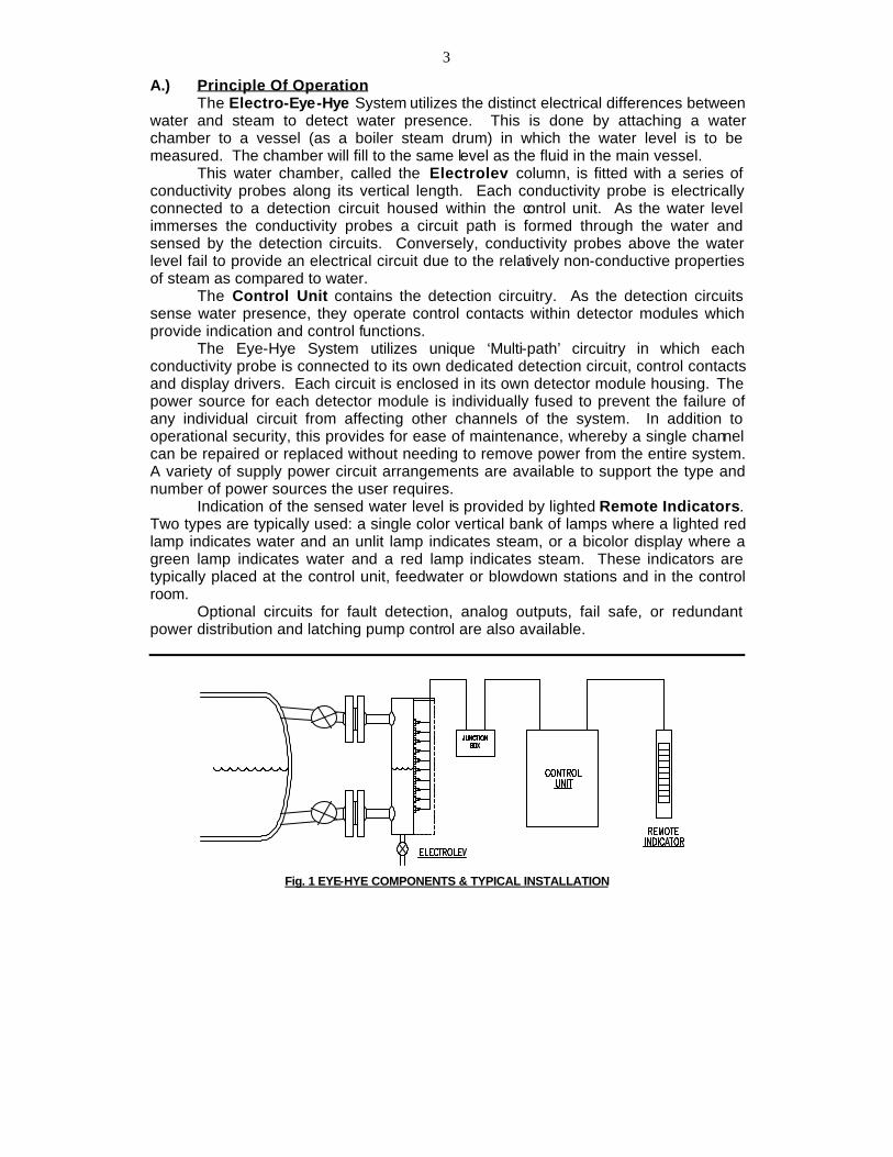
A.) Principle Of Operation The Electro-Eye-Hye System utilizes the distinct electrical differences between water and steam to detect water presence. This is done by attaching a water chamber to a vessel (as a boiler steam drum) in which the water level is to be measured. The chamber will fill to the same level as the fluid in the main vessel. This water chamber, called the Electrolev column, is fitted with a series of conductivity probes along its vertical length. Each conductivity probe is electrically connected to a detection circuit housed within the control unit. As the water level immerses the conductivity probes a circuit path is formed through the water and sensed by the detection circuits. Conversely, conductivity probes above the water level fail to provide an electrical circuit due to the relatively non-conductive properties of steam as compared to water. The Control Unit contains the detection circuitry. As the detection circuits sense water presence, they operate control contacts within detector modules which provide indication and control functions. The Eye-Hye System utilizes unique ‘Multi-path’ circuitry in which each conductivity probe is connected to its own dedicated detection circuit, control contacts and display drivers. Each circuit is enclosed in its own detector module housing. The power source for each detector module is individually fused to prevent the failure of any individual circuit from affecting other channels of the system. In addition to operational security, this provides for ease of maintenance, whereby a single channel can be repaired or replaced without needing to remove power from the entire system. A variety of supply power circuit arrangements are available to support the type and number of power sources the user requires. Indication of the sensed water level is provided by lighted Remote Indicators. Two types are typically used: a single color vertical bank of lamps where a lighted red lamp indicates water and an unlit lamp indicates steam, or a bicolor display where a green lamp indicates water and a red lamp indicates steam. These indicators are typically placed at the control unit, feedwater or blowdown stations and in the control room. Optional circuits for fault detection, analog outputs, fail safe, or redundant power distribution and latching pump control are also available.
Fig. 1 EYE-HYE COMPONENTS & TYPICAL INSTALLATION

4
B.) Components: The Electro Eye-Hye System consists of three primary items, which are: 1.) The Electrolev water column and Conductivity Probes. 2.) The Control Unit containing the Electro Eye-Hye electronic circuits. 3.) The local and remote Indicator(s) (type and number may vary based on system requirements). C.) Unpacking and Inspection: Upon receipt of the Eye-Hye System examine the containers for damage. Report any suspicious conditions as soon as possible to your carrier to avoid acceptance of damaged goods. Clark-Reliance will not be responsible for goods damaged in shipping or storage, or subsequent loss or damage due to improper storage or exposure as a result of damage to shipping containers. Verify all materials are present as recorded on the Packing List provided with each shipment. Report any discrepancies to Clark-Reliance immediately. Have the Clark-Reliance order number and shipping waybill available at time of calling. D.) Installation 1. The Electrolev should be installed on the boiler drum or vessel, as shown in Fig. 1. The distance between the Electrolev and the boiler drum should be kept to a minimum. A slope in the steam leg running from the drum or vessel towards the Electrolev of not less than 1 inch of fall for each 50 inches of linear length is recommended. The water leg should be installed with a downward slope running from the Electrolev to the drum or vessel. Care should be taken to insure no restriction or ‘trap’ occurs in the pipework which may lead to an accumulation of sediment, resulting in a restriction of flow to or from the Electrolev column. Isolation (Shut-off) valves should be installed to permit maintenance of the Electrolev while the vessel is pressurized. The standard vessel connections are 1" male pipe projections. Flanged or female socket weld connections are available options. A drain valve should be installed at the bottom of the Electrolev, as shown in Fig. 1. The standard drain connection on the Electrolev is 1/2" female socket-weld. If the steam leg piping should be left exposed to encourage the formation of condensate flow to the Electrolev column (to promote heat transfer to minimize density related errors), it is recommended that shields or guards be fitted to reduce the risk of contact with hot surfaces. It is recommended that the water leg piping between the boiler drum and the Electrolev be insulated. Insulation will reduce the effects of cooling and will provide added personnel protection from hot piping. The Electrolev column may be insulated by field personnel, or with a Flexpak insulation jacket available from Clark-Reliance. 2. The Control Unit is provided in a variety of enclosures. Standard ECIL-**R model Control Units may be mounted up to 1000 feet away from the electrolev. The Control Unit should be mounted in an area that is accessible for inspection and below 150º F. Refer to the dimensional drawings specific to the materials ordered for mounting dimensions.
5
3. The Remote Indicator(s) should be mounted for ease of viewing by the operator in accordance with operational considerations and applicable codes. There is no practical distance limitation between the Control Unit and the Remote Indicator. All Remote Indicators are designed for panel mounting. Weatherproof enclosures are available for outdoor installations. Wall mounting brackets are also available from Clark-Reliance. Refer to dimensional drawings of specific products for panel cutouts and mounting dimensions. E.) Interconnecting wiring: 1. Field Wiring from the Electrolev is terminated in the Control Unit at connector SK3. Connections should be made as illustrated on the field wiring diagrams provided for the specific equipment ordered. The Electrolev is furnished with a 30" length of high temperature wire leads exiting from the conduit connection. Longer leads are available as an option and may have been furnished on request. Model Wire Specifications EL450, EL1000 18 GA. Stranded Teflon insulated conductors rated at 300 VAC and 200ºC / 392ºF EL1800, ELF3000 18 GA. Stranded Teflon-treated glass braided rated at 600 VAC and 450ºC / 842ºF Nickel coated copper Conductor - UL #5107
High temperature probe to junction box wire specification
The high temperature probe wires should be routed to the Control Unit or a junction box (furnished by C-R, when specified). Low temperature Multi-conductor cable may be routed from the junction box to the Control Unit. The number of required conductors is equal to the number of conductivity probes, plus one for the common connection. For example a twelve probe Electrolev would require 13 conductors. (note: for increased reliability a termination for a redundant common wire to the Electrolev is provided at the Control Unit. An additional conductor would be needed if this feature is employed.) Model Wire Specifications EL450, EL1000, 18 GA. Stranded (Tinned Copper) EL1800, ELF3000 PVC insulated, rated at 300 VAC and 60º C / 140º F
Junction box to control unit wire specification
2. The power connection to the Control Unit is suitable for 12 to 20 GA. wire. The power terminals provide for single or dual power source connections. Connect AC power source to SK4 L1A & L2A for single power source operation or when using the Power Source Diverter option. For split power source operation where one of two sources supply power to the odd or even channels, remove on board jumpers J1 & J2 and connect source #1 to SK4 L1A & L2A and source #2 to SK4 L1B & L2B.

6
3. Between the Control Unit and the Remote Indicator(s) the number of conductors required for a Remote Indicator equal the total number lamps plus one for a common conductor. For example, an MTI-12B Remote Bicolor Indicator has 12 red lamps, 12 green lamps, and one common. Therefore, 25 conductors are required. Connections for Remote Indicators are made at SK1 terminals 1 to 39. Refer to the Remote Indicator field wiring diagram furnished with the system for connections relating to the equipment supplied. Indicators may be wired in parallel, for multiple indicator installations. All Remote Indicators are powered with 24 VAC from the Control Unit Model Wire Specifications All :STI, MTI 18 GA. Stranded (Tinned Copper) & SMI models PVC insulated, rated at 300 VAC and 60º C / 140º F (Belden #8468 or equal).
Remote indicator wire specification
4. Alarm and trip wiring is provided at SK2 terminals 1 to 36. A single form “C” contact is provided for generation of control and alarm functions for each channel. Contacts are rated at 5 Amp @ 120/240 VAC or 1 Amp @ 120 VDC., 5 Amp @ 30 VDC. Inter-connections between multiple channels can be made for various fail-safe or voting logic methods. Additional alarm and trip contacts can be obtained by using the contacts associated with the Remote Indicator circuits when no Remote Indicator is employed. Insure that jumpers J4 through J15 are removed before using remote display driver circuits for alarm or trip functions. Refer to the specific equipment assembly drawings provided with your system for further information on this feature. (Note: consult Clark-Reliance prior to using this feature). F.) System Options (Note: Refer to fig. 5 for location of system components.) 1. The Flexpak Insulation jacket provides a flexible insulation wrap for the Electrolev Column. This reduces heat loss and protects against accidental contact with hot surfaces on the Electrolev. The Flexpak can be specified with the original order, or ordered to retrofit an existing system. Flexpak jackets are designed for easy removal or installation with Velcro fasteners. When ordering for retrofit applications specify the serial number of the existing Electrolev. This information is located on the nameplate which is attached to the probe housing. The serial number will enable Clark-Reliance personnel to specify properly the Flexpack jacket for your application. 2. Test Switch Circuits are provided to enable operators / users to test indicator lamps and all relay circuits. On ECIL-**R models the test function is performed with an accessory printed circuit board attached to the PL 1 connector on the main control board. This board is field wired to a momentary normally open push button. The push button is furnished in a weather resistant enclosure for convenient mounting. 18 Ga. wire is sufficient for Test Switch interwiring. Refer to actual wiring diagrams for more details.
7
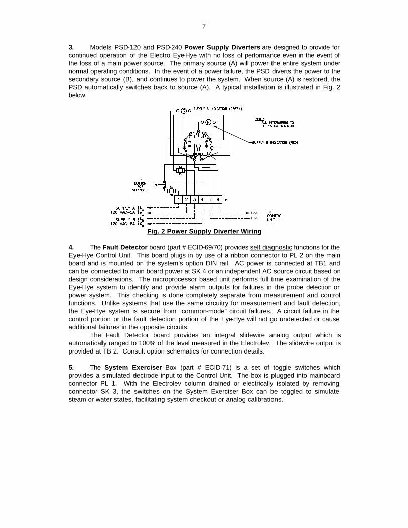
3. Models PSD-120 and PSD-240 Power Supply Diverters are designed to provide for continued operation of the Electro Eye-Hye with no loss of performance even in the event of the loss of a main power source. The primary source (A) will power the entire system under normal operating conditions. In the event of a power failure, the PSD diverts the power to the secondary source (B), and continues to power the system. When source (A) is restored, the PSD automatically switches back to source (A). A typical installation is illustrated in Fig. 2 below.
L2AL1A
Fig. 2 Power Supply Diverter Wiring
4. The Fault Detector board (part # ECID-69/70) provides self diagnostic functions for the Eye-Hye Control Unit. This board plugs in by use of a ribbon connector to PL 2 on the main board and is mounted on the system’s option DIN rail. AC power is connected at TB1 and can be connected to main board power at SK 4 or an independent AC source circuit based on design considerations. The microprocessor based unit performs full time examination of the Eye-Hye system to identify and provide alarm outputs for failures in the probe detection or power system. This checking is done completely separate from measurement and control functions. Unlike systems that use the same circuitry for measurement and fault detection, the Eye-Hye system is secure from “common-mode” circuit failures. A circuit failure in the control portion or the fault detection portion of the Eye-Hye will not go undetected or cause additional failures in the opposite circuits. The Fault Detector board provides an integral slidewire analog output which is automatically ranged to 100% of the level measured in the Electrolev. The slidewire output is provided at TB 2. Consult option schematics for connection details. 5. The System Exerciser Box (part # ECID-71) is a set of toggle switches which provides a simulated electrode input to the Control Unit. The box is plugged into mainboard connector PL 1. With the Electrolev column drained or electrically isolated by removing connector SK 3, the switches on the System Exerciser Box can be toggled to simulate steam or water states, facilitating system checkout or analog calibrations.
8
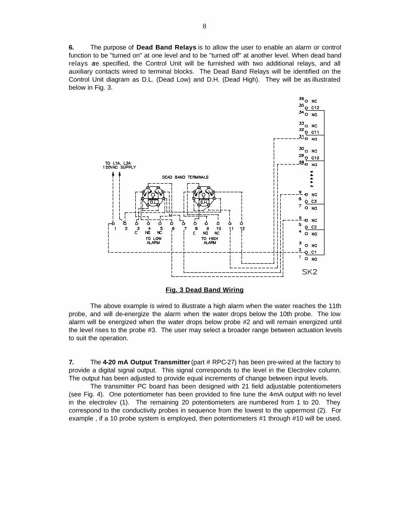
6. The purpose of Dead Band Relays is to allow the user to enable an alarm or control function to be "turned on" at one level and to be "turned off" at another level. When dead band relays are specified, the Control Unit will be furnished with two additional relays, and all auxiliary contacts wired to terminal blocks. The Dead Band Relays will be identified on the Control Unit diagram as D.L. (Dead Low) and D.H. (Dead High). They will be as illustrated below in Fig. 3.
Fig. 3 Dead Band Wiring
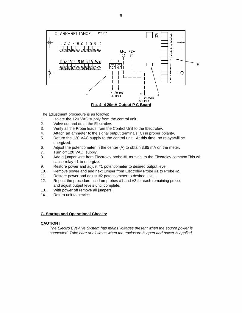
The above example is wired to illustrate a high alarm when the water reaches the 11th probe, and will de-energize the alarm when the water drops below the 10th probe. The low alarm will be energized when the water drops below probe #2 and will remain energized until the level rises to the probe #3. The user may select a broader range between actuation levels to suit the operation. 7. The 4-20 mA Output Transmitter (part # RPC-27) has been pre-wired at the factory to provide a digital signal output. This signal corresponds to the level in the Electrolev column. The output has been adjusted to provide equal increments of change between input levels. The transmitter PC board has been designed with 21 field adjustable potentiometers (see Fig. 4). One potentiometer has been provided to fine tune the 4-mA output with no level in the electrolev (1). The remaining 20 potentiometers are numbered from 1 to 20. They correspond to the conductivity probes in sequence from the lowest to the uppermost (2). For example , if a 10 probe system is employed, then potentiometers #1 through #10 will be used.
9
Fig. 4 4-20mA Output P-C Board The adjustment procedure is as follows: 1. Isolate the 120 VAC supply from the control unit. 2. Valve out and drain the Electrolev. 3. Verify all the Probe leads from the Control Unit to the Electrolev. 4. Attach an ammeter to the signal output terminals (C) in proper polarity. 5. Return the 120 VAC supply to the control unit. At this time, no relays will be
energized. 6. Adjust the potentiometer in the center (A) to obtain 3.85 mA on the meter. 7. Turn off 120 VAC supply. 8. Add a jumper wire from Electrolev probe #1 terminal to the Electrolev common.This will
cause relay #1 to energize. 9. Restore power and adjust #1 potentiometer to desired output level. 10. Remove power and add next jumper from Electrolev Probe #1 to Probe #2. 11. Restore power and adjust #2 potentiometer to desired level. 12. Repeat the procedure used on probes #1 and #2 for each remaining probe, and adjust output levels until complete. 13. With power off remove all jumpers. 14. Return unit to service. G. Startup and Operational Checks: CAUTION !
The Electro Eye-Hye System has mains voltages present when the source power is connected. Take care at all times when the enclosure is open and power is applied.
A
B
C

10
Fig. 5 Typical Control unit component arrangement (ECIL12R shown)
11
Electrolev Commissioning: Initial warm-up of the Electrolev column should be done gradually. To do this, keep the water valve closed, open the drain valve widely, and crack open the steam valve for a few minutes. Then, close the drain valve, and slowly open the steam and water valves fully. Check for any leakage at the conductivity probes. Hot-torquing is recommended on all installations. After initial warm-up, the Electrolev column should be isolated and the drain valve opened. After insuring the column is drained and pressure relieved, re-torque T, V, or Z type probes to 40 Ft Lb., (54 Newton-Meters) and F type probes to 90 Ft Lb. (122 Newton-Meters) After torquing is complete, close the drain valve and return the Electrolev to service. Hot-torquing of the conductivity probes insures proper sealing and extends the sealing gasket life. Note: FSB probes do not require hot-torquing. Control Unit and Remote Indicators: Verify all wiring is in accordance with drawings for the specific model Electro Eye-Hye and any installed options purchased. Remove the two tubular glass fuses at the power transformer and apply source power to the system. Verify AC source power is within specifications. Verify transformer output between source side of 8 amp fuse and SK 5 terminal “C” is between 24 and 32 VAC. Remove source power and install fuses. Re-apply power and observe the system is energized at the Local (if supplied) and Remote Indicators. Isolate the Control Unit from the Electrolev by removing SK 3 from the main board mating plug. By using the optional System Exerciser Box (see instructions provided with unit) or individually shorting between SK 3 terminal 13 and each of the terminals 1 through 12 in sequence verify a change of the detector status from steam to water by the illumination of the internal red LED within each of the detector modules and an indication of water on any Local and Remote Indicators. Remove all jumpers or System Exerciser Box and re-connect SK 3. Verify all indications agree with water level in the Electrolev. H. Maintenance 1. Cleaning: Blow down of the Electrolev column should be performed as needed to clear any accumulations of debris in the column and pipework. Blow down should be conducted weekly or less frequently, based upon water quality. Blow down is performed correctly by closing the water valve and slowly opening the drain valve for approximately 15-30 seconds. A brief blow down is sufficient. Excessive blow down may shorten the life of the probes.
2. Probe Replacements:
Clark-Reliance probes require very little maintenance. We suggest weekly blow downs of the water columns to prevent the build-up of contamination on the probes. A bypass switch can be installed on fuel cutout circuits. This switch will prevent a false trip during blow-down. The blow-down procedure is conducted thoroughly by closing the water valve and opening the drain valve slightly for about 20 seconds. (Refer to Clark-Reliance Form E156-B, “Recommended Blow-Down Practices for Water Columns, Electrolevs, and Water Gages) If blowing-down of the column does not clean the probes sufficiently, use a stainless steel wire brush or fine emery cloth to clean the stainless steel rod portion of the probe. To clean the insulator, use a soft cloth and a mild detergent.

12
If probes are removed at any time for replacement or inspection, the sealing gasket must be replaced. Probe replacement kits are furnished with two spare gaskets. The gasket part numbers are as follows:
Probe Type Gasket part Number T WCM-13 V X175500 (Formerly E10-10) ZG E10-10S FG E10-10S Replacing the probes:
1. Close both steam and water valves and drain the column before starting probe maintenance.
2. Remove probe to be inspected or replaced, after the column has cooled. 3. When replacing the probes, coat the threads lightly and uniformly with a high
temperature anti-seize type lubricant such as ‘Never-Seize’, ‘MolyCote G’ or ‘Fel-Pro C’
4. Torque the probes as follows: - Type T, V, ZG or ZB to 40 Ft-Lb. (54 Newton-Meters) - Type FG or FB Probes to 90 Ft-Lb. (122 Newton-Meters)
Hot torquing is suggested for all probes (except FSB). However, the column must be isolated from service with the drain valve open before re-torquing the probes.The hot torquing procedure will extend probe sealing gasket life and should be performed as follows:
1. Partially open steam valve to warm up the column with the drain valve slightly open. 2. Close steam (and water) valves to isolate the column. 3. Open the drain valve completely. 4. Re-torque as instructed above. 5. Return to service by closing the drain valve and opening the steam and water valves.
Note: When installing the high temperature wire to the probe, use an open end wrench to prevent the probe assembly from turning while tightening the wire terminal nut. Use a ¼” wrench for both the compression nut and the terminal nuts on T and V type probes. ZG and FG type probes require a ½” wrench for the compression nut and a 3/8” wrench for the terminal nut.
13
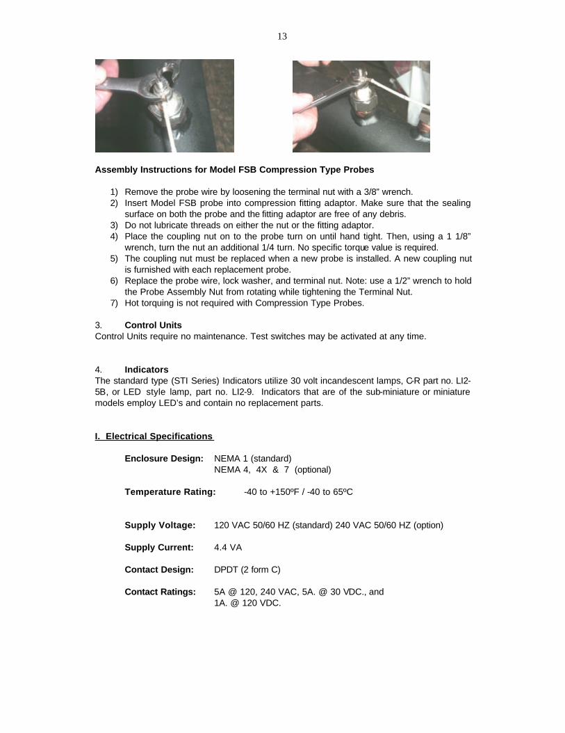
Assembly Instructions for Model FSB Compression Type Probes
1) Remove the probe wire by loosening the terminal nut with a 3/8” wrench. 2) Insert Model FSB probe into compression fitting adaptor. Make sure that the sealing
surface on both the probe and the fitting adaptor are free of any debris. 3) Do not lubricate threads on either the nut or the fitting adaptor. 4) Place the coupling nut on to the probe turn on until hand tight. Then, using a 1 1/8”
wrench, turn the nut an additional 1/4 turn. No specific torque value is required. 5) The coupling nut must be replaced when a new probe is installed. A new coupling nut
is furnished with each replacement probe. 6) Replace the probe wire, lock washer, and terminal nut. Note: use a 1/2” wrench to hold
the Probe Assembly Nut from rotating while tightening the Terminal Nut. 7) Hot torquing is not required with Compression Type Probes.
3. Control Units Control Units require no maintenance. Test switches may be activated at any time. 4. Indicators The standard type (STI Series) Indicators utilize 30 volt incandescent lamps, C-R part no. LI2-5B, or LED style lamp, part no. LI2-9. Indicators that are of the sub-miniature or miniature models employ LED’s and contain no replacement parts. I. Electrical Specifications Enclosure Design: NEMA 1 (standard) NEMA 4, 4X & 7 (optional) Temperature Rating: -40 to +150ºF / -40 to 65ºC Supply Voltage: 120 VAC 50/60 HZ (standard) 240 VAC 50/60 HZ (option) Supply Current: 4.4 VA Contact Design: DPDT (2 form C) Contact Ratings: 5A @ 120, 240 VAC, 5A. @ 30 VDC., and 1A. @ 120 VDC.

14
Contact Life: Mechanical - 5 million operation Electrical - 100,000 operations min. at full load. Probe Circuit Current: 1.5 mA @ 12 VAC per probe. Sensitivity: 50,000 Ohms Listing: Factory Mutual #2N2A4.AF, CSA # LR14001, and UL listed Detector Modules
15
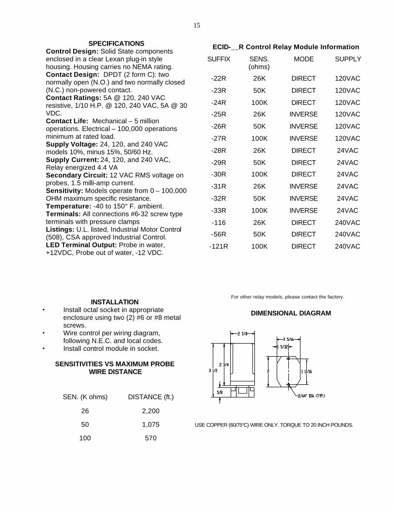
INSTALLATION
• Install octal socket in appropriate enclosure using two (2) #6 or #8 metal screws.
• Wire control per wiring diagram, following N.E.C. and local codes.
• Install control module in socket.
SENSITIVITIES VS MAXIMUM PROBE WIRE DISTANCE
SPECIFICATIONS Control Design: Solid State components enclosed in a clear Lexan plug-in style housing. Housing carries no NEMA rating. Contact Design: DPDT (2 form C): two normally open (N.O.) and two normally closed (N.C.) non-powered contact. Contact Ratings: 5A @ 120, 240 VAC resistive, 1/10 H.P. @ 120, 240 VAC, 5A @ 30 VDC. Contact Life: Mechanical – 5 million operations. Electrical – 100,000 operations minimum at rated load. Supply Voltage: 24, 120, and 240 VAC models 10%, minus 15%, 50/60 Hz. Supply Current: 24, 120, and 240 VAC, Relay energized 4.4 VA Secondary Circuit: 12 VAC RMS voltage on probes, 1.5 milli-amp current. Sensitivity: Models operate from 0 – 100,000 OHM maximum specific resistance. Temperature: -40 to 150° F. ambient. Terminals: All connections #6-32 screw type terminals with pressure clamps Listings: U.L. listed, Industrial Motor Control (508), CSA approved Industrial Control. LED Terminal Output: Probe in water, +12VDC, Probe out of water, -12 VDC.
570 100
1,075 50
2,200 26
DISTANCE (ft.) SEN. (K ohms)
240VAC DIRECT 100K -121R
240VAC DIRECT 50K -56R
240VAC DIRECT 26K -116
24VAC INVERSE 100K -33R
24VAC INVERSE 50K -32R
24VAC INVERSE 26K -31R
24VAC DIRECT 100K -30R
24VAC DIRECT 50K -29R
24VAC DIRECT 26K -28R
120VAC INVERSE 100K -27R
120VAC INVERSE 50K -26R
120VAC INVERSE 26K -25R
120VAC DIRECT 100K -24R
120VAC DIRECT 50K -23R
120VAC DIRECT 26K -22R
SUPPLY MODE SENS. (ohms)
SUFFIX
ECID-__R Control Relay Module Information
DIMENSIONAL DIAGRAM
USE COPPER (60/75°C) WIRE ONLY. TORQUE TO 20 INCH POUNDS.
For other relay models, please contact the factory.

16
J. System Component Supply Current: Part # Component Current @ 120 VAC
ECIL-10R Control Unit .37 A ECIL-12R Control Unit .44 A ECIL-20R Control Unit .74 A SMI-10BR Sub-Miniature Indicator .04 A SMI-12BR Sub-Miniature Indicator .04 A SMI-20BR Sub-Miniature Indicator .06 A MTI-10 Miniature Indicator .09 A MTI-12 Miniature Indicator .10 A MTI-20 Miniature Indicator .18 A MTI-10B Miniature Indicator .09 A MTI-12B Miniature Indicator .10 A MTI-20B Miniature Indicator .18 A STI-10 Standard Indicator .38 A STI-12 Standard Indicator .45 A STI-20 Standard Indicator .76 A
K. Trouble - Shooting Guide Symptom Probable Cause Corrective Action
1. Indicator Lamp illuminated above level, or remains on during blow-down
1 A) Failed/Short-circuited probe
1 A) Remove probe and clean if contaminated, or replace if leakage is detected.
1 B) Shorted/Open circuit in field wiring
1 B) Check all wires and connections for short circuits and proper connections
2. Indicator lamp out at any level
2 A) Single Lamp failure on STI Series indicator
2 A) Replace lamp P/N: LI2-5B
2 B) All Indicators not illuminated due to power out or loss of signal or ground wire.
2 B) check 8 amp fuse on power panel in control unit. Verify all wiring and terminations.
2 C) Single LED not illuminated on models with LED indicators, problem is either failed LED, faulty detector module or wiring problem.
2 C) Replace detector module. Verify all wiring and terminations. Replace remote display (unit is not field repairable)
3. Control circuits inoperative 3 A) faulty detector module or open wiring circuit
3 A) Replace detector module. Verify all wiring connections.

17
Consult the factory or your local Clark-Reliance Representative with any questions. Technical questions can be promptly answered, if the caller provides the system serial number (Example EE - _ _ _ _ _ ) or the drawing numbers.

18
16633 Foltz Parkway Strongsville, OH 44149 USA Phone (440) 572-1500 Fax (440) 238-8828
[email protected] www.clark-reliance.com
clark-reliance.com/parts
"PARTS-PLUS"
Critical spare parts for overnight delivery, direct from the manufacturer.
Steel Valve Repair Kit
Bronze Valve Repair Kit
Replacement Probes Gage Glass Repair Kit Simpliport Module
Simpliport Packing Nut Replacement Relays Probe Repair Kit Replacement EA100
Replacement Micro-switch
Valve Packing Replacement Floats

19