Electricity Supply - PRDR Sustainable Energy for...
66
Pre-Feasibiity Study: Solar Photovoltaics for Replacing up to 50% of Diesel Generation in Nauru July 2013
Transcript of Electricity Supply - PRDR Sustainable Energy for...

Pre-Feasibiity Study:
Solar Photovoltaics for Replacing up to 50% of Diesel Generation in Nauru
July 2013

ACRONYMS
ARM.....................................................................................................Atmospheric Radiation Measurement
AUD..................................................................................................................Australian Dollars (Currency)
AusAID................................................................................................Australian Foreign Aid Organization
EU...........................................................................................................................................European Union
FY........................................................................................................Fiscal Year (1 July-30 June for Nauru)
GIZ...............................Deutsche Gesellschaft für Internationale Zusammenarbeit (German Aid Agency)
GWh..................................................Gigawatt hours - Thousands of millions of Watt hours (million kWh)
HV................................................................................................................................................High Voltage
IRENA............................................................................................International Renewable Energy Agency
JICA.................................................................................................Japan International Cooperation Agency
kV.....................................................................................................................kilo-Volts (thousands of volts)
kW....................................................................................................................kilowatts (thousands of Watts)
kWh.................................................................................................kilowatt hours (thousands of Watt hours)
kWp...............................................................kilowatts peak (solar panel rating at standard solar conditions)
LED................................................................................................................................Light Emitting Diode
MVA........................................................................................................Mega-Volt-Amperes (power rating)
MW.............................................................................megawatts (thousands of kilowatts, millions of Watts)
MWh................................................................megawatt-hours (thousands of kWh, millions of Watt-hours)
MWp............................................................Megawatts peak (millions of Watts peak in solar panel ratings)
NASA......................................................................National Aeronautics and Space Administration (USA)
NUC........................................................................................................................Nauru Utility Corporation
OTEC......................................................................................................Ocean Thermal Energy Conversion
PEC............................................................................................................Pacific Environment Community
PIGGAREP.............................Pacific Island Greenhouse Gas Abatement and Renewable Energy Project
PV........................................................................................................Photovoltaic (solar electric generation)
SPC.......................................................................................................Secretariat of the Pacific Community
TEPCO................................................................................................................Tokyo Electric Corporation
UNDP............................................................................................United Nations Development Programme
USD..............................................................................................................United States Dollars (currency)

TABLE OF CONTENTS
1 ELECTRICITY SUPPLY .................................................................................................................... 1
1.1.1 ELECTRICITY SUPPLY.......................................................................................................................................11.1.2 FUTURE CHANGES IN ENERGY DEMAND........................................................................................................4
2 RENEWABLE ENERGY RESOURCES IN NAURU ....................................................................... 4
3 CURRENT RENEWABLE ENERGY USAGE .................................................................................. 6
4 SOLAR TECHNOLOGY OPTIONS .................................................................................................. 7
4.1 GRID-CONNECTED SOLAR PHOTOVOLTAICS WITH NO ENERGY STORAGE........................................84.2 STAND-ALONE POWER FOR INDIVIDUAL BUILDINGS, GROUPS OF BUILDINGS OR COMMUNITIES.. .94.3 POWERING THE GRID ENTIRELY BY SOLAR DURING THE TIME WHEN THE SUN IS PROVIDING ENERGY....................................................................................................................................................... 114.4 LARGE SCALE SOLAR WITH STORAGE THAT CONTINUOUSLY CONTRIBUTES TO THE LOAD..........11
5 ESTIMATED COST STRUCTURE ................................................................................................ 12
5.1 ENERGY STORAGE OPTIONS............................................................................................................ 145.2 ADDING ENERGY EFFICIENCY MEASURES........................................................................................165.3 DESIGN INNOVATION...................................................................................................................... 17
6 CONCLUSIONS ................................................................................................................................ 18
7 REFERENCES ................................................................................................................................... 19
APPENDIX 1 - TRANSFORMER FEEDER LOAD MEASUREMENTS .......................................... 21
APPENDIX 2 - DIESEL-RENEWABLE ENERGY HYBRID SOLUTIONS: TRANSITION TO SUSTAINABLE ENERGY SYSTEMS FOR THE PACIFIC REGION ................................................ 22
DIESEL POWER SYSTEMS................................................................................................................................ 22MEETING DEMAND: ACTIVE POWER & FREQUENCY CONTROL.........................................................................23REACTIVE POWER & VOLTAGE CONTROL........................................................................................................ 23SPINNING RESERVES...................................................................................................................................... 24RE INTEGRATION IMPACTS............................................................................................................................ 25RE INTEGRATION.......................................................................................................................................... 26CURRENT POWER SYSTEM............................................................................................................................. 28LOW PENETRATION SYSTEM.......................................................................................................................... 28MEDIUM PENETRATION SYSTEM.................................................................................................................... 29LOW GENERATOR LOADING........................................................................................................................... 30RE VARIABILITY & GENERATOR CYCLING........................................................................................................31HIGH PENETRATION SYSTEM.......................................................................................................................... 33

1 ELECTRICITY SUPPLY
Nauru is moving along in a process of shifting from what amounted to free electricity for residences to tariffs that recover the real cost of power which is close to USD $0.50 per kwh. Donor inputs, particularly from Australia, the European Union, Taiwan and Japan, have been generous and the power system is back to a reasonable standard of reliability though there is still much to be done to rehabilitate the aging power plant and grid if that reliability is to be maintained for the longer term.
A National Energy Policy from 2009 is in place and the government has established goals for the reduction of fuel imports through increased use of renewable energy (with a target to reach 50% of the overall supply) and improved efficiency of both supply and demand.
To help coordinate this transition and help relieve Nauru from its almost total dependence on fossil fuels, the government has asked IRENA and the Germany Agency for International Cooperation (GIZ) working within the Secretariat of the Pacific Community (SPC) for assistance in developing a road map, essentially a long term action plan, to achieve national energy goals. An initial draft is expected in the third quarter of 2013.
1.1 The NUC
Originally a part of the National Phosphate Corporation, in 2011 the Nauru Utility Corporation (NUC) became an independent, government owned utility responsible for both public electricity and public water supply for Nauru as well buying, selling, storing and transporting fuel.
Nauru’s non-industrial electricity supply comes from a single power station operated by
NUC while RONPHOS, the phosphate company generates its industrial power, and the Australian regional processing centre for asylum seekers generates its own power. The NUC power is generated by four ageing medium-speed Ruston stationary engines with a high-speed Cummins generator also available to provide stand-by capacity. Two other well-used engines and generators were recently provided by AusAID and are in Nauru but need substantial investment for refurbishment and support equipment plus treatment for the tropical climate before they can be put on line as reliable gensets.
The serviceable engines have a nameplate total of 11.852 MVA power generation capacity but are greatly derated due to age and condition. The distribution system includes 11 kV, 3.3 kV and 415 V sections. Maximum demand was once in excess of 7 MW but has dropped, largely due to the loss of industrial demand, to around 3.3 MW.
Table 1 – NUC Generation 2008-2012
Year Actual generation MWh
2008 19,3822009 21,1742010 22,4622011 23,0242012 23,600
Source NUC 2013
Table 2 – Prepaid meter customers (2012)
Sector Number of prepaid customers
Residential 1980Commercial 124
Industrial 0Government 0
Source NUC 2012

During the years of high phosphate production, industrial use dominated the Nauru energy economy. That use has greatly diminished and the domestic sector is now the dominant user.
Mainly due to problems with collections, almost all residential meters have been changed to prepayment type units though most commercial, government and industrial customers remain on post-pay meters that are read each month. While this has increased residential collections dramatically, obtaining data about actual kWh usage per month is no longer possible without also physically reading the meters each month. Also there are concerns that the number of households that are wiring around the pre-payment meters to avoid any payments has increased since NUC personnel are no longer visiting the residences every month. Again, the irregularity of pre-paid power purchases has made it nearly impossible to prepare monthly kWh records to scan for customers that appear to be seriously underpaying their expected kWh usage and can be reasonably suspected of power theft.
Even though there are not many public streetlights on Nauru and their consumption is not large, conversion to high-efficiency LED lights is being considered. A number of LED type streetlights powered directly by solar energy have been provided through grants from Taiwan but some are already not operating due to vandalism and technical problems. Some domestic and most commercial, government and industrial customers are still on standard post-pay meters (Table 3) making it simple to analyse their usage in order to best fit renewable energy systems to their needs.
Table 3 – Post-Pay meters in Nauru (2011)District District Name total Domestic Commercial Government Industrial
1 Aiwo 46 15 23 2 62 Anabar 4 0 4 0 03 Anetan 3 0 2 1 04 Anibare 2 0 2 0 05 Baitsi 5 1 1 3 06 Boe 3 0 1 2 07 Buada 2 1 1 0 08 Denig 26 17 6 3 09 Ewa 1 0 1 0 010 Ijuw 0 0 0 0 011 Meneng 13 5 4 4 012 Nibok 4 1 1 2 013 Uaboe 0 0 0 0 014 Yaren 14 1 6 6 1
Total 123 41 52 23 7
Source NUC 2013
Daily load curves for 2010, as shown in Figure 1 below, indicate a weekday base-load of around 2MW and a strong evening peak of around 3.2MW, possibly due to cooking using electric stoves. The weekend load varies from around 2.5 to 3MW with the peak again in the evening. There is little demand for heating, apart from cooking.

Figure 1 – Load curves for 2010

Source NUC 2011
For the weekday load, approximately one-half of the energy is delivered between 0700 and 1800 hours. For the weekend the evening peak is more dominant and about one-half the total energy is delivered between about 0700 and 1900 hours. Up to date hourly generation data is needed for an accurate determination of load patterns but that data is not available at the time of this writing.

Detailed energy use for the residential sector is difficult to determine due to the use of pre-payment meters for almost all residential customers. Data is available from post-
Table 4– Energy use by sector (Post paid meters only) FY 2011 and FY 2012
TARIFF 2011 AUD 0.20 AUD 0.25 AUD 0.50 AUD 0.50
TARIFF 2012 AUD 0.25 AUD 0.30 AUD 0.50 AUD 0.50
Month Domestic Commercial Industrial Government Total kWh
Jul-10 37,763 267,189 63,991 96,704 465,647
Aug-10 34,826 174,593 31,674 462,636 703,728
Sep-10 29,452 318,162 37,274 100,945 485,833
Oct-10 37,535 296,720 33,266 99,979 467,500
Nov-10 147,973 238,622 27,250 118,237 532,082
Dec-10 41,769 171,093 36,218 109,555 358,634
Jan-11 23,293 158,288 38,407 93,755 313,743
Feb-11 20,897 102,681 25,666 78,530 227,774
Mar-11 32,565 94,198 30,244 115,146 272,153
Apr-11 39,475 168,234 128,032 112,141 447,882
May-11 27,228 160,452 173,356 81,771 442,807
Jun-11 46,327 230,436 115,020 94,984 486,767
Jul-11 42,465 263,291 29,500 48,791 384,047
Aug-11 43,394 302,905 35,844 48,498 430,641
Sep-11 29,460 232,113 29,840 55,213 346,626
Oct-11 31,529 231,865 32,160 46,494 342,049
Nov-11 33,004 274,511 31,042 46,892 385,449
Dec-11 40,088 296,791 37,522 52,590 426,991
Jan-12 38,077 288,962 32,588 39,924 399,551
Feb-12 36,507 242,422 33,390 41,674 353,993
Mar-12 32,172 251,414 30,008 44,876 358,470
Apr-12 31,017 269,832 30,056 41,784 372,689
May-12 34,307 412,097 31,338 54,921 532,663
Jun-12 34,918 281,303 33,944 57,911 408,076
Yearly Average 473,018 2,864,088 563,815 1,071,976 4,972,897
Source – NUC 2013

payment meters for Domestic, Commercial, Industrial and Government Sectors, however. Table 4 shows the energy metered using standard (post-paid) meters in use as of mid 2012. By subtracting the post-payment meter kWh from total kWh delivered, most of the remaining energy will be from the residential sector but the non-technical and technical losses for all sectors will be included in that number and in Nauru that is substantial. Since NUC calculates its cost of production at close to USD $0.50 per kWh, both residential and commercial customers are heavily subsidised.
1.1.1 Future changes in energy demandDue to the major structural changes taking place in the Nauru economy necessitated by the large reduction in phosphate shipments in recent years and resulting shift from a positive trade balance to one that is negative, forecasting future energy use is uncertain. It is possible that fuel use will not increase, and may even decrease, over the next decade as electricity prices are increased from the heavily subsidised levels of today to a tariff that recovers full cost. Also, industrial fuel use is closely tied to phosphate production, which has had a long-term downward trend. It presently appears that only the use of jet fuel may have any significant growth over the next 10 years and that is not likely if Our Airline (the national airline of Nauru) does not further expand its operations.
2 RENEWABLE ENERGY RESOURCES IN NAURU
Staff working on renewable energy and energy efficiency activities are currently part of NUC and to date have been primarily responsible for energy efficiency campaigns and renewable energy project implementation. Though alternate energy use has been mentioned in development strategies since the 1980s, prior to the acceptance of the Nauru Energy Policy Framework in 2009, goals for renewable energy implementation were not specifically considered in any legislation, regulations or corporate actions. No projects for renewable energy were installed before 2006 except for a small number of solar water heaters installed in the 1980s by the Public Works Department on government financed housing. There is little use of biomass for cooking and, for all practical purposes, there was no significant use of renewable energy until 2006 when the EU REP-5 project installed 40 kWp of grid-connected solar panels on Nauru College. In 2012, a 30kWp solar PV system was installed on the government buildings in Yaren district and 132kWp was installed at the power plant, bringing the total grid-connected renewable energy generation capacity to 202kWp. Since 2010, there also have been some installations of solar home systems, solar-powered water pumps and the distribution of solar powered torches to households.
Solar. Measurements show an excellent average solar resource of over 6 kWhr/m2/day (with solar panels oriented and tilted to the angle that maximises energy input) with a seasonal variation of around 10-15% (Table 5). Although solar PV offers electricity generation that can supplement the existing diesel generation, due to the unpredictably variable nature of the resource, expensive electrical storage systems will be required for it to be included into the grid at high levels of penetration. A dynamic model has not yet confirmed the maximum possible level of solar penetration before grid stability issues occur, but it is likely to be limited to around 20% - 30% of the midday demand. Above this threshold, storage and additional control systems may have to be introduced to ensure

grid stability. This still means that a total 600 kWp to 1 MWp of relatively inexpensive solar PV without storage can probably be installed without grid stability problems and even 1 MWp (30% noon time penetration) could be possible though dynamic modelling of the grid should be carried out before committing to that high a level of solar penetration. In terms of energy production, a 30% midday demand penetration by solar without storage represents around a 5% energy penetration for the conditions in Nauru.
Table 5 – Nauru solar energy received at the ground (kWh/m2/day)Tilt Jan Feb Mar Apr May Jun Jul Aug Sep Oct Nov Dec Avg
15° Tilt 5.71 6.24 6.14 6.10 6.34 6.23 6.28 6.43 6.47 6.48 6.34 5.73 6.23
Source – NASA (https://eosweb.larc.nasa.gov/sse/)
Wind. Data collection, funded by PIGGAREP1 and the EU, has been carried out for more than three years at a telecommunications tower at Anabar District on the northern part of the island where the wind resource is expected to be greatest. Unfortunately, tower components near the measurement instruments that may change both the speed and direction of the wind seen by the instruments lowers confidence in the collected data.
Thus, Nauru’s wind resource is not yet accurately known although, based on airport, NASA wind data and the data recently collected from instruments on the telecommunications tower, it is probably only marginally cost-effective at present fuel prices. Measurements already made at the tower indicate an annual average wind resource of 4.22 m/sec at 30 metres (about 4.7 m/sec if extrapolated to 50 metres) for 2009-2011. These figures are at the low end of practicality for wind energy generation. A resource assessment using a more suitable 50 metre guyed mast is underway and is intended to determine the appropriateness of further wind energy development and to assess the quality of the data already collected from the nearby telecommunications tower.
Biomass. With little or no biomass left in the mostly mined out upper plateau that forms 90% of Nauru’s land area, there are insufficient biomass resources for either combustion for electricity or significant production of biofuels. Land rehabilitation possibly could result in topside biofuel plantations if fast growing species suited to the poor soil that remains can be found, but there are no plans for trials and certainly no production will be seen within the next decade.
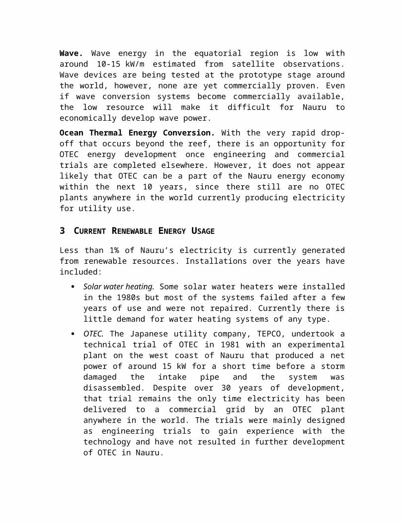
Wave. Wave energy in the equatorial region is low with around 10-15 kW/m estimated from satellite observations. Wave devices are being tested at the prototype stage around the world, however, none are yet commercially proven. Even if wave conversion systems become commercially available, the low resource will make it difficult for Nauru to economically develop wave power.
Ocean Thermal Energy Conversion. With the very rapid drop-off that occurs beyond the reef, there is an opportunity for OTEC energy development once engineering and commercial trials are completed elsewhere. However, it does not appear likely that OTEC can be a part of the Nauru energy economy within the next 10 years, since there still are no OTEC plants anywhere in the world currently producing electricity for utility use.
1 PIGGAREP funded the first 12 months (2009-2010) of the wind data collection. The EU funded an additional two years (2010-2011).

3 CURRENT RENEWABLE ENERGY USAGE
Less than 1% of Nauru’s electricity is currently generated from renewable resources. Installations over the years have included:
Solar water heating. Some solar water heaters were installed in the 1980s but most of the systems failed after a few years of use and were not repaired. Currently there is little demand for water heating systems of any type.
OTEC. The Japanese utility company, TEPCO, undertook a technical trial of OTEC in 1981 with an experimental plant on the west coast of Nauru that produced a net power of around 15 kW for a short time before a storm damaged the intake pipe and the system was disassembled. Despite over 30 years of development, that trial remains the only time electricity has been delivered to a commercial grid by an OTEC plant anywhere in the world. The trials were mainly designed as engineering trials to gain experience with the technology and have not resulted in further development of OTEC in Nauru.
Grid-connected Solar on Nauru College. In 2008, the REP-5 project of the EU installed a 40 kWp grid-connected installation on the roof of Nauru College appears to have reliably met its energy production expectations and is considered a successful trial of the technology. NUC states that the installation produced 157,336 kWh from June through October 2011.
Solar Home Systems. Sixty solar home systems of 130 Wp capacity, which included LED lights, have been provided by Taiwan though their operational status is not known. All were installed on homes already connected to the grid so only the lighting load is affected.
Solar Streetlights. Taiwan also funded a solar street lighting project which included 155 units installed around the island along the main coastal road, with some of the larger units installed in community areas and government buildings and smaller units installed in less travelled residential areas.
Solar Powered Water Pumping. Although some 160 Wp arrays for solar-powered district water pumps have been installed through JICA funding, details of their number or status are not available. A few households have private solar water pumping systems, although the number and capacity of those is not known.
Solar Powered Torches. Solar powered torches with LED lights donated by Taiwan were recently distributed to households. Further information was not available at the time of writing as to their status or their expected benefits.
Grid-connected Solar on Government Buildings. A grid-connected PV system with an installed capacity of 15.84 kWp was provided by Taiwan and installed at the government offices building in 2012. In late 2012 this was expanded to a total of 30kWp. No operational data is being systematically collected.
Telecommunications. Solar PV and small-wind turbines with batteries were installed on power poles sometime in 2009 with the intention of powering a telecommunications system. However, the project was not completed as intended

and some of the batteries were used for alternative purposes, while some of the solar PV panels and wind turbines remain unused.
Solar Distillation Units. Twenty solar stills for water purification were purchased and installed on private residences in areas with a particular vulnerability to water shortages. Their status is unknown as there is no monitoring.
Grid Connected Solar for Power Generation. In 2013, a grid-connected solar installation of 132 kWp was installed across two roofs on government buildings near the power plant that is intended to offset the electrical energy needed to operate the reverse osmosis plant that was installed through the PEC fund of Japan in early 2013. Operational data is not yet available.
Thus far, the experience with grid-connected solar installations has been good and the installations have had high reliability with effectively no maintenance costs. Although in the future, wind may prove to be an economically reasonable energy resource, solar energy is currently the only renewable resource known to be suitable for off-setting existing fossil fuel usage in Nauru and for at least the initial investments in renewable energy to reach the 50% renewables goal, solar is clearly the technology most appropriate for installation.
4 SOLAR TECHNOLOGY OPTIONS
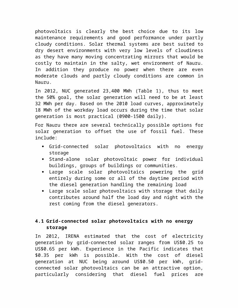
In order to reduce the need for fossil fuel generation through solar energy, two technologies have been shown to be cost effective for commercial, utility grade solar installations, solar photovoltaics and solar thermal energy conversion. Solar photovoltaic generation is by far the most common technology in use around the world for solar electricity production but solar thermal also has been successful in some environments. For Nauru, solar photovoltaics is clearly the best choice due to its low maintenance requirements and good performance under partly cloudy conditions. Solar thermal systems are best suited to dry desert environments with very low levels of cloudiness as they have many moving concentrating mirrors that would be costly to maintain in the salty, wet environment of Nauru. In addition they produce no power when there are even moderate clouds and partly cloudy conditions are common in Nauru.
In 2012, NUC generated 23,400 MWh (Table 1), thus to meet the 50% goal, the solar generation will need to be at least 32 MWh per day. Based on the 2010 load curves, approximately 18 MWh of the workday load occurs during the time that solar generation is most practical (0900-1500 daily).
For Nauru there are several technically possible options for solar generation to offset the use of fossil fuel. These include:
Grid-connected solar photovoltaics with no energy storage Stand-alone solar photovoltaic power for individual buildings, groups of buildings
or communities. Large scale solar photovoltaics powering the grid entirely during some or all of
the daytime period with the diesel generation handling the remaining load Large scale solar photovoltaics with storage that daily contributes around half the
load day and night with the rest coming from the diesel generators.

4.1 Grid-connected solar photovoltaics with no energy storage
In 2012, IRENA estimated that the cost of electricity generation by grid-connected solar ranges from US$0.25 to US$0.65 per kWh. Experience in the Pacific indicates that $0.35 per kWh is possible. With the cost of diesel generation at NUC being around US$0.50 per kWh, grid-connected solar photovoltaics can be an attractive option, particularly considering that diesel fuel prices are expected to rise over the coming years while the solar generation cost per kWh will remain approximately the same for the life of the installation. There are two basic problems that limit the use of grid-connected solar generation in Nauru:
1. It only generates electricity when the sun is shining so there is no capacity available at night.
2. The generation from the solar varies greatly over the day and, due to the passage of clouds on partly cloudy days, some variations are rapid making it necessary to have some sort of spinning reserve (diesel engines on line but not generating at full capacity) or some form of energy storage available if the total amount of solar input is to be more than a few per cent of the existing load.
To reach the 50% goal, under even 100% clear sky conditions, grid-connected solar without storage would not be sufficient by itself since . In 2010, around 18 MWh/day occurred during the sunny hours with 16 MWh of load outside the time when solar generation is practical. However, grid-connected solar can be a significant component of a larger solar installation that includes storage; unfortunately grid-connected solar without storage by itself is unlikely to be able to provide more than 10% of generation and even that level would be difficult to achieve with the existing power plant and its old, medium speed diesels that are relatively slow to respond to load changes. The general rule of thumb for grid-connected solar is that at noon (when the sun is providing the most energy) the output from the solar should not be more than 20% of the load if grid stability is to be maintained. New control technologies are becoming available that may allow that number to increase to as much as 60% of the noon-time load, but noon is the maximum solar input in any 24 hour period and there is still zero generation during the hours when the sun is down. If at noon-time 60% of the power generated comes from solar, that means that is its peak generation and the rest of the time its output will be less. After sunset and before sunrise the generation from solar will be zero. So the actual percentage of daily energy generated – even with 60% of the noon-time load provided by solar energy – will not likely be more than around 20% though that will depend largely on what time of the day the main loads occur.
All methods of solar input that can reach the 50% goal in Nauru will need to include large amounts of relatively low cost grid-connected solar without storage to help cover the daytime load, but much of the energy will need to come from solar that is associated with some form of energy storage; in the case of Nauru almost certainly some type of battery.
As much as possible of the grid connected solar without storage should be roof mounted. This reduces the problems of locating and allocating land to ground mounted solar arrays,
it automatically reduces the dawn to dusk variations in solar generation through the varying orientations, locations and tilt of roofs that are available for solar panel mounting, it reduces problems of connection to the grid and roof mounting generally places the solar generation at the site of a load thereby reducing line and transformer losses.
Another mounting system that is often used to avoid land issues for grid-connected solar installations without storage is the use of the solar arrays to shade parking areas and stadium seating. The panel mounting cost is somewhat higher than standard ground mounted arrays but the system serves a double purpose and has no land cost. Also, recent trials of power pole mounted solar panels with micro-inverters has shown promise and could relatively inexpensively add over 100 kWp of solar PV to the grid in Nauru.
4.2 Stand-alone power for individual buildings, groups of buildings or communities
In this approach, suggested for study by NUC as potentially attractive, some components of the load would be taken off the grid and powered entirely by solar energy systems that include substantial storage for energy delivery when the sun is down. A re-connection to the diesel powered grid would remain possible in case of loss of solar power or extended cloudy periods that reduce solar input below the design level causing the batteries to discharge.
As an example of this concept, government buildings have a much higher load during the day than at night. This means that the storage needed to power them for 24 hours will be substantially less than that needed to power customers with a high night-time load such as those in most residential areas. In early 2013, the loading of the outputs from ground mounted transformers were checked in the evening and mid-day. Table 6 shows the results. Although at least hourly readings for feeder loads will be needed before a specific solar development plan can be prepared, it appears that feeders to government buildings, the new police station, and the old hospital have substantially higher loads during the day than at night and appear likely to be the most cost effective choices for fully converting to solar power. Based on the sectoral energy use data in Table 4, government represents about 1 GWh per year in energy use which probably could be met by around 1 MWp of solar associated with sufficient storage to cover the modest night time load as well as covering daytime variations. Assuming that the commercial and industrial sectors also are primarily daytime users of electricity – as it appears from the initial transformer loading measurements in Table 5 – a total of 5 MWp of solar could probably be deployed in this scenario, providing around 20-25% of the total energy delivered by NUC.
Much of the residential load is delivered through pole mounted transformers and unfortunately those could not be easily measured during the study period though it is clear that the evening residential load is substantially higher than the load during the peak solar hours of the day thus increasing the percentage of expensive energy storage that would be required to take the residential feeder loads off the diesel powered grid.
Although this approach would allow commercial and government loads to be taken off the grid by solar in a more cost effective manner than would be the case if residential

loads are included – and therefore could be immediately attractive to donors for funding – no more than half the 50% goal could be met by this approach alone.
Advantages:
Loads that best match the timing of solar input can be selected thereby reducing the need for expensive energy storage. When using solar to totally power buildings and groups of end users that have high daytime loads and low loads at night, installing relatively inexpensive solar without storage can largely offset much of the daytime load so only moderate storage would be needed to provide for the much lower loads at night and to provide stable generation when the solar input changes during the day.
Several relatively small solar plants would be used instead of a whole-grid sized plant. Under this scenario, solar can be added in stages with each new solar power plant taking over an additional section of the grid. This would allow the NUC to more gradually adjust to the mix of solar and diesel power. Also the loss of one of several solar power systems each suppling perhaps 10% of the load would not be such a serious problem as the loss of a single plant providing 50% of the load.
Disadvantages
Increased connection cost. There would be substantial added expense to install the power lines and switchgear necessary to connect the individual solar plants ‘topside’ to the transformers at the end use sites on the coast.
Increased problems with arranging for land access and power line rights of way. Multiple power plants mean multiple problems in securing access to sufficient land and securing the right-of-way for each of the power lines needed to connect the power plants with the transformer feeding the load selected for that plant.
Somewhat higher installation cost per kWp of solar than a large whole-grid solar plant. Site preparation and materials transport cost would most likely be higher for multiple sites.
Added complexity for design and project development and operation. Since each plant would need to be specifically designed to fit the load being served, each plant would be a separate design and tendering process which is likely to result in different components being used and different operating control systems installed. A whole-grid plant could be a single design problem which could be addressed under one project concept though actual construction could be staged to fit funding availability.
Most of the Nauru load is residential and does not fit well with this model. In Nauru, the sectors with a high daytime load appear to be dominated by air conditioning loads in public buildings and offices with the peak load for residential customers occurring sharply in the evening hours between about 1900 and 2200. Though precise data is not available, the residential load appears to be at least 75% to 80% of the total energy generated by NUC so the benefits of this approach would be modest if any.
Overall, this approach is not recommended. While it could be an attractive approach for taking some exclusively daytime loads off the grid, as a strategy to reach the 50% goal the disadvantages appear to outweigh the modest cost advantages.

4.3 Powering the grid entirely by solar during the time when the sun is providing energy
An approach that minimises the investment in energy storage is for the solar to take over the entire NUC load for at least some of the time during the day when there is some solar input. The most cost effective time for solar to take over the load is around noon when the solar energy peaks but to achieve 50% of the total energy generated, all the daytime load and a percentage of the night time load will need to be provided by solar. Under this scenario, battery storage would be included both to maintain the output during the day as the solar varies over the day and to help offset the evening peak load in order to allow the night time load to typically be carried by two of the NUC diesel engines instead of the current three.
Advantages:
Minimises overall cost of storage. All generation during the daylight hours would maximise the use of solar without storage and therefore minimise the amount of energy storage needed to meet the 50% goal.
May allow one engine to be kept off-line as a standby. Without hourly load data, it is not possible to determine the amount of load that has to be carried by the diesels, but if the solar storage can sufficiently trim the evening peak to eliminate the need for three of the NUC diesels to be on line at that time, taking one of the older engines off line entirely may be possible on most days.
Disadvantages:
No comparable installations. Standalone solar plants of multi-megawatt size are state-of-the art and present significant challenges in terms of design and obtaining the necessary equipment and control systems. There would be substantial risk of technical problems, at least initially, and without experience from other installations to provide O&M cost examples, accurately predicting the per kWh cost will not be possible.
Load shifting. Twice a day, 100% of the load would need to be shifted from the diesel plant to the solar plant. While technically possible, to do that smoothly on a daily basis will require skilled operators and properly functioning data and control links between the solar plant and the diesel power house. In the Nauru environment, those requirements may be hard to maintain.
Savings in storage cost may not offset risks. Although storage is minimised through this approach, the savings appears to be less than 10% of the system cost, though the exact amount cannot be estimated without accurate load data.
Given the high risk of technical problems for this cutting-edge type of installation and the modest cost saving possible, this approach is not recommended.
4.4 Large scale solar with diesel and solar both continuously availalble to contribute to the load
The approach preferred by NUC to provide solar generation for grid supplementation is to design the solar system to reduce the diesel load sufficiently to allow one engine to be taken off line except as a backup for those unusual times when extended cloudy periods occur and the solar input is not adequate. While technically this design approach can
work well it does mean that storage must be sufficient to cover a significant percentage of the load on demand 24 hours a day even though the solar panels are providing utility level energy only 5 to 6 hours a day. Although panel costs have plummeted in the last few years, storage prices remain high making the cost of energy from such a facility likely to be somewhat higher than that of the existing diesels though the actual costs are quite dependent on the detailed timing of the load and that has yet to be established for NUC’s current operating conditions.
This approach has been used in a number of solar-diesel hybrid installations around the world with success and has the most operational experience of the options that include large scale energy storage to provide access to energy 24 hours a day.
Advantages:
Low cost for connection to the grid. For this type of installation that will be feeding the entire grid, access to the grid from topside solar farms is not a major problem since there is an HV transmission line running topside that could be easily accessed plus the coastal HV line is not far from the topside areas that would be suitable for large scale solar sites.
Load levelling. By being online 24 hours a day, the diesel-solar interface can be adjusted to provide the best fuel efficiency for the engines through load levelling and through the use of the diesels for battery bank charging when the external load is low and engines are lower in fuel efficiency.
Experience with similar installations. This approach has been used in a number of solar-diesel hybrid installations around the world with success and has the most operational experience of the options that include large scale energy storage to provide access to solar energy 24 hours a day. While this installation could be the largest of its type in the world, similar plants larger than 1 MW are operational and could be scaled up using existing, commercially available components.
Disadvantages:
The whole plant needs to have a consistent design. Because the various components of all solar installation have to work in an integrated fashion, all must use the same power conditioning components so that battery charging and power delivery can be managed properly. With multiple donors providing funds this can be difficult to arrange, particularly when the installation is to be built in stages, not all at one time.
There may need to be an upgrade of the main HV transmission line topside. Until better data regarding the power flows through the grid are provided by NUC, the adequacy of the HV line to which the solar plant would need to connect cannot be determined.
Of the approaches technically possible for Nauru, this conventional solar-diesel hybrid design approach is the one that is considered most likely to succeed and is the one recommended though it is slightly more costly than a solar installation that would provide 100% of the daytime load plus part of the evening peak load.

5 ESTIMATED COSTS AND BENEFITS
Because the solar investment required to meet 50% of generation is very dependent on the load and its diurnal pattern, to provide a proper estimate of costs and benefits hourly data for the present load is required. The data available at the time of this study is three years old and of questionable quality plus it is likely that the increased tariff and economic adjustments that have occurred since 2009 and 2010 have caused changes in the characteristics of the load. Therefore at this point, only basic cost-benefit calculations can be made with confidence though those should be adequate to indicate whether the addition of 50% solar generation can be expected to be comparable in energy delivery cost to the existing all diesel power system.
The 2012 installation for Tokelau – a location with worse construction material access problems than Nauru – saw the total cost of the solar arrays with battery storage come to about USD 7 per installed Wp of solar. Since that time, a further reduction in solar panel cost has occurred. Also the storage requirement for Nauru will be a smaller percentage of the total cost because in Nauru it will be a hybrid solar-diesel system and solar is required to provide only 50% of the load, not 90% as in Tokelau. So less than USD 7 per Wp of solar with storage can probably be achieved in Nauru. For basic grid-connected solar without storage, recent quotations in the region indicate an installed cost of less than USD 4.50 is achievable. The actual cost of the storage component will be very dependent on the load pattern but for this initial rough estimate, it is assumed to be approximately USD 2.00 per total installed Wp of solar.
.General Assumptions:
1. 50% of generation on Nauru = 32 MWh per day2. Diesel fuel efficiency = 3.5 kWh/litre of fuel burned.3. Installation with storage = USD 7 per Wp of solar.4. Installation without storage = USD 4.5 per Wp of solar.5. Estimated storage cost for Nauru = USD 2.00 per total Wp of solar.6. Daily energy production required = 32 MWh from solar.7. Existing load between 0900-1500 (prime solar hours) = 18 MWh/day.8. Remaining load outside of prime solar hours = 14 MWh.9. Energy provided by diesel 0900-1500 = 5 MWh (one engine at optimum fuel
efficiency load).10. Energy from solar without storage 0900-1500 = 13 MWh.11. Energy from solar with storage to meet 50% goal = 19 MWh.12. Residential, commercial and Nauru government load growth will be minimal or
negative. Increased industrial load growth will be take care of directly by industry.
Solar Assumptions
1. Solar input: Once hourly load data becomes available, hourly modelling using ARM data from ground measurements will be possible but at this point it is reasonable to assume the solar input for the average month to be the 6.23 Peak Solar Hours per day measured by NASA satellites (Table 4).
2. Reduction in solar output due to cell temperature above 25C = 15%

3. Reduction in solar output due to non-optimum orientation = 5%4. Reduction in solar output due to uncompensated glass reflection = 5%5. Reduction in solar output due to dirt accumulation = 5%6. Reduction in solar output due to ageing = 10%7. Wiring losses = 5%8. Inverter losses = 8%9. Battery losses = 20% (lead-acid batteries near their end of life)10. Maximum average depth of discharge = 30% (required for lead-acid batteries)11. Average battery life = 10 years12. Average power converter life = 10 years13. Power converter cost = USD 600 per kW14. O&M excluding battery and inverter replacement = 1% of installation cost
Using the above assumptions, to deliver 1 MWh during the day with no storage requires about 280 kWp of solar panels and to deliver 1 MWh from battery storage at night requires about 360 kWp of panels to charge the battery – energy conversion losses in the battery means more solar array input is needed to provide the same output from batteries at night as a solar array that is delivering its energy directly to the grid during the day.
Table 6 – Amount of solar capacity needed to meet the 50% of generation goal
Load to be served
Energy delivery required
(MWh)
Size of solar array
(MWp)
Minimum size of power
conversion system (MW)
Estimated cost (USD
million)
Daytime load to be carried by solar using solar without storage 13 3.64 3 16.4
Night time load for solar with storage 19 6.84 4 47.9TOTAL 32 10.48 7 64.3
Under this scenario, the annual energy delivered by all solar would be about 12,775 MWh/year or 350,400 MWh over the 30 year life of the solar. At USD 0.90 per litre for diesel fuel, the 2012 cost of diesel including the estimated cost of storage and handling, it should result directly in a fuel savings of about USD 3,500,000 per year, a reduction in power plant maintenance of an estimated USD 0.25 million per year, plus increased engine efficiency of up to 10% due to load levelling by the energy storage may save an additional USD 0.35 million per year in fuel. Finally, some savings will accrue to the solar because the generation by solar is distributed around the island and closer to the load so there are lower lines losses. This may result in a saving on the order of USD 0.1 million per year. Thus the solar can reasonably be expected to result in a total annual saving of around USD 4.2 million.
Table 7 – Estimated annual savings in diesel generation cost due to 50% generation by solar
Component of Diesel Savings Millions of USDCost of diesel fuel saved through 12,775 MWh coming from solar 3.50Reduction in power plant O&M cost (other than fuel) due to cutting generation by half 0.25Increased diesel engine efficiency due to load control through the energy storage component 0.35Reduced system losses through the addition of solar (generation on site for grid-connected solar) 0.10TOTAL Annual Saving to NUC 4.20

Assuming the cost of the major components is amortized according to the life cycle of those components, the 6.84 MWp solar component that includes storage would have panels amortized over 30 years and the batteries amortized on a 10 year replacement cycle. Also inverters can be expected to have a life of at least 10 years and can also be amortized on a 10 year replacement cycle. Operation and Maintenance costs that are left after replacing the inverters and batteries can reasonably be assumed to be no more than 1% per year of the installed cost. Table 8 shows that accumulated annualized cost.
Table 8 – Annualized cost of the solar installation with storage (30 year plant life)Component of Solar Cost Millions of USD
Amortization of capital cost of solar panels and installation (30 yr) 0.95Amortization of capital cost of inverters (10 yr replacement) 0.24Amortization of capital cost of batteries (10 yr replacement) 2.10O&M excluding battery or inverter (1% of initial investment) 0.48TOTAL estimated annual O&M cost of the solar component with storage 3.77
For the component of the solar installation that is without storage (3.64 MWp), the panels would be amortized over the 30 year life of the installation and the inverters replaced on a 10 year cycle. Operation and Maintenance costs that are left after replacing the inverters are assumed to be 1% per year of the installed cost. Table 9 shows that estimated annual cost.
Table 9 – Annualized cost of the solar installation without storage (30 year plant life)
Component of Solar Cost Millions of USDAmortization of capital cost of solar panels and installation (30 yr) 0.49Amortization of capital cost of inverters (10 yr replacement) 0.18O&M excluding battery or inverter (1% of initial investment) 0.16TOTAL estimated annual O&M cost of the solar component without storage 0.83TOTAL estimated annual O&M cost of solar (sum of both the section of the solar plant without storage and the section with storage)
4.6
Although the rough estimate of the annual solar cost of generation is about USD 0.4 million higher than the estimated annual savings on diesel generation, the accuracy of the data used to do the estimation has a low confidence level and the difference, USD 0.4 million, is well within the range of probable error. This result is consistent with the observed range of cost of energy delivery for existing solar-diesel hybrid systems and is essentially indicating that if diesel costs continue to be the same for the next 30 years, the cost of the solar generation will be about the same as the savings in diesel generation. That diesel costs will remain the same for even the short term is highly improbable because major investment is going to be needed to rehabilitate the existing diesel power plant and that will increase the effective cost of diesel generation. Also the diesel fuel price is predicted to increase over the longer term directly increasing the cost of diesel generation over time. Currently, battery storage prices are predicted to fall over the long term and inverter and panel prices are not expected to rise. Thus it is highly likely that the solar will provide substantially greater savings over its 30 year life than this estimate. Finally, the solar arrays are not expected to have to be replaced during their 30 year life and therefore their cost of energy delivery will not be significantly affected by monetary inflation, though the O&M cost relating to batteries and power conversion equipment will be increased as inflation occurs.

A substantial added benefit could be the use of the solar panels as rainwater collectors through the addition of large underground storage tanks to accept water collected from the approximately 10 ha of solar panels that will need to be installed.
Other benefits that can be expected to accrue from the addition of 50% solar generation include:
1. Substantially reduced carbon emissions2. Lowered risk of environmental pollution by fuel and oil spills3. Lowered risk of economic effects resulting from fuel price variations4. Lowered requirement for desalination of sea water to meet fresh water needs
due to collection of rainwater runoff on the approximately 10 ha of solar panels that are installed
What this means is that at this time, installing sufficient solar generation to take over 50% of the existing diesel generation is an appropriate measure both environmentally and financially over the long term but adding the solar should not be expected to lower the cost of generation relative to what it is today with the 100% diesel plant.
5.1 Energy storage options
To meet the 50% goal, substantial storage will be required. Four types of energy storage are technically feasible for Nauru: (1) capacitor storage, (2) flywheel energy storage; (3) pumped storage using seawater; and (4) battery storage.
Flywheel storage has been successfully used for the very short term storage needed to mitigate rapid variations in load but not for the longer term storage needed in Nauru.
Super-capacitor storage is also good for short term storage to help stabilize the grid as it has the capability to be charged and discharged very rapidly to offset rapid changes in solar generation and loads. The first solar installation in the Pacific using storage of this type will be made in Tonga starting in 2013 with funding by JICA. The super-capacitors will be designed to stabilize the output from the new 1 MWp grid-connected solar array to be constructed on Tongatapu. However, it is not yet technically or economically feasible for capacitors to store the amount of energy needed to allow the solar to be a stand-alone generator, conventional spinning reserve remains necessary.
Although it is technically possible to install a large seawater reservoir topside, fill it during the day using solar pumps and then run the water back to the sea through turbines to generate electricity at night, in Nauru the highest point above the sea is not great enough for that process to be cost effective even if the land can be made available for the very large reservoir needed plus the around 9 ha of land likely to be needed for the solar panels.
Only battery storage has both the flexibility and the possibility of being cost effective for Nauru. Of the available battery technologies, the most commonly used for this scale of storage is the lead-acid battery (as is used in the six other Pacific Island installations that are using solar as their primary generation source), the sodium-sulphur battery and the Lithium-ion battery. Lead-acid batteries are readily available, they use a familiar technology and have been proven to work over the long term. However, they are not well

matched to large scale solar storage for utility use. They cannot be consistently discharged more than 30% of their capacity and be expected to last 10 years or more, they can be damaged and their life shortened if too rapidly charged or discharged, and there must be a high quality, carefully controlled and regulated charging/discharging control system to transfer the solar generated energy to the battery and from the battery to the load.
Although industrial grade lead-acid batteries have thus far worked satisfactorily in the existing Pacific installations, the Nauru system would be more than an order of magnitude larger than any of the other Pacific installations and problems with lead-acid batteries increase as the size of the energy storage increases because either very expensive super high capacity batteries need to be made to order or many commercially available cells need to be connected in parallel to meet the storage capacity requirements which requires expensive charge balancing controls if acceptably long life is to be achieved. Nauru probably can be better served by the higher capacity and more flexible lithium-ion or possibly sodium-sulphur batteries that are now available and being further developed for utility grade installations.
Sodium sulphur batteries are excellent for utility type storage as they have high energy densities and long life and use low cost materials. They are commercially available but have the major disadvantage of having to operate at 300°C to 350°C to create the proper internal conditions for energy storage plus the sodium polysulfides in the batteries are very corrosive and the sodium itself spontaneously ignites when exposed to air causing the batteries to represent a significant environmental and safety hazard. For Nauru, they are not likely to be technically practical or appropriate.
The lithium-ion battery is also commercially available. It can be very rapidly charged and discharged with no damage, requires no physical maintenance other than assuring connections remain clean and tight, can be very deeply discharged with no damage and can be expected to have an operational life around double that of industrial grade lead-acid batteries. Because part of the internal materials are flammable, there are concerns about the possibility of fires and the batteries should be kept in a fire secure location such as a separate concrete enclosed room. However, the batteries are much less of an environmental hazard than large lead-acid batteries or sodium sulphur batteries and can be safely managed by the NUC. Because the lithium-ion battery is expected to be in great demand for electric vehicles, the price is predicted to fall rapidly over the next few years and by the time the Nauru installation is ready for procurement, Li-ion batteries may well be comparable in cost to lead-acid batteries for the storage capacity needed.
5.2 Adding energy efficiency measures
To keep investment in solar generation as low as possible, it is vital that investment in solar generation be in parallel with investments in energy efficiency improvements. An investment in energy efficiency to save energy will be more cost effective than installing the solar generation needed to deliver that amount of saved energy. The cost of incremental energy efficiency measures do, however, increase as the level of efficiency increases but for saving up to around 20% to 30% of the existing demand, it is reasonable to expect that the investment needed for each kWh saved will be less than the cost of generating it. Although available data is inadequate to allow for an accurate estimation of

the potential in Nauru for energy efficiency measures to reduce demand – and therefore the amount that can be saved in reduced solar investment – it clearly is substantial, almost certainly in excess of 20% and possibly as high as 30%. Although NUC tariffs have increased in recent years, residential energy costs are still heavily subsidised and the message being sent to residential consumers through those subsidised tariffs is not one of investing in energy efficiency or practicing conservation. Specific programmes to engage the public in actions that improve their efficiency of energy usage are therefore needed to reduce the power plant load and in turn make it less costly for renewable energy to take over 50% of that load.
Of particular interest is the possibility to reduce the substantial energy needed to operate multiple reverse osmosis plants to produce fresh water. If rainwater is collected and stored from the runoff from the 10 MWp of solar panels, the requirement for desalination energy to produce fresh water could be greatly reduced if not eliminated most of the year.
Government should be the driver of these programmes and as such needs to take the lead in improving its own efficiency of energy use. Improving government energy efficiency will need to be a major component of any action plan designed to reach the 50% renewable energy goal. Additional requirements for a successful national energy efficiency programme include:
1 Determination of just how residences use energy. Focused energy efficiency incentives and programmes cannot be established without first undertaking a residential energy use survey. That will need to include a detailed survey that creates an inventory of all energy using devices in each household and their pattern of usage.
2 If the survey indicates that there are many households using electric cooking, a programme can be established to exchange electric cook stoves for gas stoves combined with arrangements to reduce the supply cost of LPG. That combination can reduce the evening peak load significantly without increasing the cost of cooking for the end user.
3 Since in general it is the residences in the top half of that annual energy use spectrum that can provide the greatest increases in energy efficiency. To determine which homes those are, it will be necessary to purchase the services or software needed to provide an analysis of pre-payment meter data so NUC can have a reasonably accurate determination of the monthly and annual electricity usage of each Nauru residence. With that information, those residences that are above average in electricity usage can be the primary focus for programmes to improve energy efficiency.
4 Development and delivery of public information programmes that tell households how energy efficiency can be improved and therefore costs reduced.
5 Passing legislation making power theft a crime with substantial penalties. Publicise a date for the start of enforcement that allows customers that have wired around meters to reconnect before criminal penalties begin.
6 Preparing an action plan for improving energy efficiency in all sectors and coordinating donor investments to help donors avoid investing in projects that do not

fit into the plan and to allow large investments to be made through combining inputs from several donors.
5.3 Design innovation
With the sharp fall in solar panel costs seen in the last year, it may no longer be the best design choice to orient all panels in a solar farm toward the point in the sky that sees the maximum annual solar input. In Nauru this would see panels tilted toward the north with about 10 degrees of tilt (though tilting at the latitude angle – in Nauru’s case 0.5 degrees – is the usual angle of tilt assumed to provide the maximum annual energy, seasonal cloudiness in Nauru causes a steeper tilt to provide the highest annual solar energy generation and is also beneficial for rain runoff based self-cleaning). This approach maximizes the total energy coming from the panels but the resulting output from the solar array is sharply concentrated during the middle of the day (See Figure A3 in Appendix 2). For the times before about 1000 and after about 1400 hours, the need for increased diesel generation increases rapidly if there is no storage.
One approach to flattening the generation curve of solar power to reduce its de-stabilising effect on the grid is to use solar collectors that track the sun so they are always pointed directly toward the source of solar energy and produce the absolute maximum possible energy output. With that approach the generation curve on a clear day is quite flat from about two hours after sunrise to about two hours before sunset. However, the cost of the mountings that allow the tracking is much, much higher than stationary mounts. Complex three axis computer controlled movement is needed to properly track the sun and in the salt air of Nauru, maintenance requirements would be high.
The second approach that is sometimes used is to simply clip off the top of the solar generation curve and not use the energy at the peak, controlling it so the output from the solar is less variable and relatively constant for the five or so hours centred on noon. That approach also results in a loss of some energy from the array relative to the maximum possible but makes large arrays more acceptable to the grid with little or no storage. The added cost of the necessary control system can be significant, though new designs now under test may be more affordable in the future.
When there is storage available, it is also possible to send the excess power available in the middle of the day to storage, an approach that also will flatten the solar output available to the grid. This approach requires sophisticated controls which may increase maintenance problems due to the limited technical resources available to Nauru but should be investigated further.
An approach that may, in equatorial Nauru at least, flatten the solar generation curve and reduce the need for diesel input between about 0800 and 1000 hours without complex controls, would be to have some of the solar panels in the solar farm oriented more toward the east. To increase solar generation between about 1400 and 1600 hours would require some of the solar panels to be oriented toward the west. While those ‘misoriented’ panels would on average generate somewhat less energy over the day than those oriented toward the north, the energy they generate is relatively cheap while that from diesel is expensive plus at the equator, the reduction in daily output is low. To determine just how cost effective the approach would be in Nauru, detailed hourly load

data from NUC and detailed solar data from the ARM data archives will be needed in order to model the overall array output and determine just how much the easterly and westerly oriented panels could offset added diesel or storage costs under real solar conditions. The main advantage of that approach is there are no complex control or tracking systems involved and maintenance is no different from that of a standard fixed array.
The concept of using the solar array for rainwater collection is also an innovative design component that is recommended for consideration in the design of this installation.
6 SUMMARY AND CONCLUSIONS
Although near the cutting edge of commercial solar technology, the large scale solar generation needed to provide 50% of Nauru’s electricity is technically practical and, compared with the cost of new diesel generators and the fuel to run them for the next 20 years, solar can be a cost effective option, particularly if the forecasts of around 2% average annual increase in fuel cost and the prediction of a long term decline in storage costs are correct.
Any solar installation intended to offset 50% of the existing electricity generation will require a large amount of energy storage. The amount of energy storage needed will be the major determinant of the cost effectiveness of the approach chosen. The amount of energy storage needed is directly related to the percentage of total solar electricity that is delivered during the daytime hours since all night-time energy delivery of solar generated electricity completely depends on stored energy. Thus to optimise cost effectiveness, a design approach is needed that permits the bulk of electricity to be delivered by the solar system during the day, when solar generation occurs, with night time energy delivery minimised. This means that reducing the load at night is more cost effective than reducing it during the day so energy efficiency programmes should focus strongly on reducing night time load through energy efficient lighting, converting electric cooking to gas and reducing the need for air-conditioning for comfortable sleeping.
Thus of the options considered, the most cost effective approach would be to take over all daytime generation with solar, including only enough storage to maintain consistent output as the solar energy input changes. However, to meet the 50% goal, substantial night-time energy delivery will also need to come from the solar. That can probably be best used to reduce the diesel loading during the evening peak (around 1900-2200 hours). Unfortunately, there are no existing stand-alone solar generators of this size in operation in the world and this would mean that the Nauru installation would be experimental in nature. This represents a significant risk of failure and therefore this option is not recommended.
The recommended approach which is only slightly more costly is to create a diesel-solar hybrid system with some diesel engines always running and over all contributing half the energy delivery but in a design approach that optimises diesel engine efficiency and minimises the need for energy storage. This requires that at least one diesel engine will need to run during the day with around 70% of the daytime energy coming from solar. At nights through a combination of energy efficiency improvements intended to reduce the evening peak load and solar electricity stored in batteries, only two engines would be

needed leaving one engine continuously off-line to allow a chance for engines to be overhauled and to provide standby capacity.
Thus, in terms of action plans, it is clear that reaching the 50% goal will need to include substantial energy efficiency measures in order to lower the overall amount of renewable generation needed to meet the goal in a least cost manner.
6.1 Action plan
This large an installation is best approached in a staged manner. However for it to all work together, the entire system will need to be designed as a whole so that each stage of construction will be consistent with the overall design. All components of the final system must be compatible with each other since energy flow data must be shared between all of the system components in order for the battery charging to be properly carried out.
The proposed solar-diesel hybrid system should make the maximum practical use of grid-connected solar without storage since this option generates electricity more cheaply than the diesels at NUC. Grid-connected solar can be installed quickly and with minimum of site preparation. Therefore for the first phase of implementation following completion of the design, it is recommended that Nauru immediately encourage donor projects that add roof-top grid connected solar capacity up to a maximum total of around 500-600kWp of solar while seeking finance for the more costly installations that will require energy storage. However, all installations must use components that will function properly when integrated into the overall solar-hybrid system. Given that the three existing grid-connected solar installations all use SMA made solar inverters and since SMA inverters are the most commonly used inverters in the Pacific and have performed very well even in the harsh tropical marine environment it, is recommended that SMA units become the standard inverter type for future installations in Nauru so that all the installations can work together properly.
Since a relatively small amount of energy storage is needed to maintain grid stability and significantly extend the amount of low-cost grid-connected solar that can be added to the diesel grid, that is appropriate for the second phase of implementation which would be intended to reach the goal of about 70% of daytime load from solar. By the time that phase has reached its technical limits, the cost of energy storage may be substantially lower than it is today and the added cost of the larger amounts of storage needed to reach the 50% of total load goal may be more affordable and provide a reasonable return on investment for lenders and possibly even independent power producers.
6.1.1 Action plan step 1 - Project design
To prepare a complete system design that can be implemented in phases according to the availability of funding, detailed site and opeartional data will be needed as follows:
1. The total electrical load on an hourly basis for five weekdays and two weekends.
2. Obtain ARM horizontal, direct and diffuse solar energy records for the past five years and put into a format suitable for input to the project design.

3. Collect and analyze solar production data from existing grid-connected solar installations at the Nauru College, Government Buildings and at the NUC power house.
4. Prepare an inventory of publicly owned rooftops that are suitable for solar installation
5. Identification of parking areas at government facilities that can include solar arrays in the form of parking shades.
6. Determine the location and total number of power poles that do not have shading and are of a type that can be used for mounting solar panels on their tops.
7. Upgrade existing grid maps to clearly show existing HV and MV lines and their capacities, all transformers with their type and capacities and include a satellite view overlay showing the location of rooftops, parking lots and power poles found to be suitable for solar installation.
8. Household energy use survey to estimate the practical energy efficiency improvements that can be expected with emphasis on lowering the evening peak.
9. HV and MV line capacities, their daily loading pattern, and the location of reasonable access points for solar input.
10. Locate potential sites ‘topside’ for the large scale arrays with an emphasis on land owned or managed by government.
11. Determine the potential for large scale rainfall collection at solar arrays.
Following receipt of the necessary data, the system designer will need to work closely with solar panel, inverter and storage industry leaders to establish a design for the provision of 50% of generation from solar that is intended to (a) maximize daytime use of solar; (b) reduce the evening peak to allow one engine to remain off line on most days and (c) maximize engine fuel efficiency through storage management and (d) the design should be modular so that it can be implemented in stages of stand-alone modules of one to two MWp of solar each.
In parallel with the solar design effort, an energy efficiency programme that is specifically focused on the reduction of the evening peak load has to be submitted for funding. That programme will need to provide improved lighting efficiency, the replacement of electric cooking stoves by LPG units, improved efficiency of refrigerators and freezers, and reduced energy requirements for air-conditioning energy through equipment replacement and the modification of buildings to reduce the effects of solar heating on comfort.
6.1.2 Action plan step 2 – Installation of roof-top and parking lot grid-connected solar and preparation for the large scale solar farm installation. Carry out energy efficiency programmes.
Once the overall system design is completed and approved for implementation, obtain grant funding and install roof-top and parking lot solar using a design consistent with the

overall design concept and limited to about 600 kWp total until energy storage can be included.
Locate and purchase or obtain very long term lease on land sufficient to install one module of the large scale solar plant that includes energy storage. Seek funding commitments for the construction of the large scale solar plant construction.
Begin carrying out the energy efficiency programme intended to reduce the evening peak load.
6.1.3 Remaining steps to complete the project.
Once the initial solar farm module (one to two MWp of solar with storage) is commissioned and functioning well, the overall system design can be revised, if necessary, to provide improved performance though the basic concept will need to be retained in order to maintain overall system compatibility. Using the revised design obtain funding for completion of the project and install the remaining solar farm modules.
Total project implementation time can be expected to be as much as ten years if grant funding is to be the source of finance.
7 REFERENCES
In the preparation of this report, primary sources were used as much as possible. Personnel from the NUC and others spent considerable time in locating and providing much of the requested information as well as assisting in locating additional sources. Background information and the Appendix were sourced from:
IRENA document (in preparation) 2013 “Hybrid power systems for Pacific islands”
GIZ/IRENA document (in preparation) 2013 “Nauru Energy Sector Summary Report”
For additional background information, the following additional resources are recommended:
1) Technical Evaluation and Assessment Study of NUC Power Generation and Distribution Systems from 5 June 2013 prepared by Andrew Daka/Pacific Power Association: http://www.ppa.org.fj/wp-content/uploads/2013/04/NUC-data-handbook.pdf
2) PPA power utility benchmark report: http://www.ppa.org.fj/wp-content/uploads/2013/03/Power-Benchmarking-Main-Report-5-Feb.pdf
3) PPA facilitated NUC Handbook: http://www.ppa.org.fj/wp-content/uploads/2013/04/NUC-data-handbook.pdf
4) Nauru Utilities Corporation Act 2011: http://faolex.fao.org/docs/pdf/nau109164.pdf

1) ADB’s Asian Development Outlook 2013: http://www.adb.org/sites/default/files/pub/2013/ado2013.pdf
5) Nauru National Energy Policy May 2009
6) National Sustainable Development Strategy (Revised 2009): http://www.sprep.org/att/IRC/eCOPIES/Countries/Nauru/44.pdf
7) 2007 Demographic and Health Survey (DHS): http://www.spc.int/sdd/index.php/en/component/docman/cat_view/46-dhs/50-nauru-2007-dhs-report
8) Wind Data Evaluation after 12 Months – Anabar - Nauru Wind Power Feasibility Study from September 2010 prepared by Factor 4 Energy Projects GmbH
9) Nauru PIREP report: http://www.sprep.org/attachments/climate_change/Vol7-NauruNationalReport_000.pdf

Appendix 1 – Transformer loading measurements
Table 6 - Ground mounted transformer feeder loads
Location Phase 2000-2100 Mid-dayAmperes Watts Amperes Watts
D1R 38.7 9288 19.0 4560Y 41.0 9840 35.8 8592B 17.0 4080 17.5 4200
D2 (Topside on the way to NRC)
R 162.4 38976 176.8 42432Y 125.8 30192 120.6 28994B 124.7 29928 134.3 32232
D4 (Topside at NRC)
R 117.7 28248Y 143.1 34344B 134.8 32352
Old Hospital and RO plant for refugee processingg centre
R 27.5 6600 108.8 26112Y 33.5 8040 91.1 21864
B 15.9 3816 125.16 30038
HospitalR 89.3 21432 69.6 16704Y 69.1 16584 50.6 12144B 86.3 20712 53.7 12888
Airport120.7 28968144.0 34560180.2 43248
Court and government buildings
R 168.5 40440 262.4 62976Y 20 4800 169.1 40584B 97.4 23376 233.1 55944
New Police Station
R 28.5 6840 67.7 16248Y 57.5 13800 87.6 21024B 31.2 7488 56.4 12536
Capelli’sR 128.7 30888 150.5 36120Y 114.2 27408 138.5 33240B 98.9 23736 115.3 27672
Up the hill from Taiwan building
R 22.0 5280Y 8.2 1968B 34.2 8208
Source: NUC measurements (2013)

Appendix 2 (Adapted from the 2013 IRENA document “Hybrid power systems for Pacific islands”), to be available in the 3rd quarter of 2013 at www.irena.org/Publications
DIESEL-RENEWABLE ENERGY HYBRID SOLUTIONS: TRANSITION TO SUSTAINABLE ENERGY SYSTEMS FOR THE PACIFIC REGION
Diesel power systems
Diesel generators are the most common generation technology used for power systems in remote areas such as Pacific islands and often provide isolated communities with their first access to electricity. A number of factors make diesel generators well suited for island power generation. Diesel fuel has a high energy density which greatly reduces storage requirements versus other fossil fuels such as coal or natural gas. The generators are relatively compact and available in a wide range of capacities allowing for power plants that can be closely matched to an island’s demand. The majority of power plants in the Pacific use several diesel generators running in parallel. This gives operational flexibility as individual generators can be started up or shut down when demand changes. Multiple small generators also increase efficiency and security of supply versus a single large generator. Diesel generators have relatively quick start times and good flexibility in meeting daily and seasonal variations in demand. They provide fast response times and good power quality and are relatively simple to operate and maintain. The technology is robust and has a long track record of successful deployment.
The diesel generator includes a small battery and electrical starter motor to bring the main engine online when there is a demand for electricity. Once the engine is running a small amount of power is used to keep the starter battery charged. The fuel system stores the diesel and delivers it to the engine. The engine burns this fuel, converting chemical energy into thermal energy (waste heat) and rotational kinetic energy. The engine is attached to an alternator that converts the rotational kinetic energy into electrical energy.
Utility scale generators in the Pacific produce three-phase alternating current (AC) electricity, the same type of power generated by traditional mainland power plants. Three-phase AC is composed of three separate flows of electricity each of which are equally spaced apart and oscillate in a sinusoidal fashion. Electricity grids have three separate sets of wires, one for each phase. Electrical loads with high power demand (e.g. industrial motors) often use all three phases while common household loads such as lights and appliances use only one phase. The AC frequency is 60Hz in U.S. Pacific territories and 50Hz on all other islands. The voltage of the AC electricity produced by generators varies depending on the model but voltage is usually stepped up by a transformer to a higher level for transmission across the island and then stepped back down to a standard level for distribution to the loads of individual customers.

Meeting demand: active power & frequency control
A key fact of power generation is that the supply from generating units must always match the demand from customer loads. Whenever a light is turned on additional power must be immediately generated. When the light is switched off generators must immediately reduce their power output. Demand is constantly changing as customers switch loads on and off at their convenience. This can lead to sudden spikes and drops in demand as major industrial equipment is powered up or shut down or when populations arrive at home after work and power on lights and appliances and then shut these loads off before going to sleep.
The power that does work on the grid, lighting a bulb or powering an oven, is called active power. The diesel generators monitor the frequency of the AC electricity being produced to sense and respond to changes in the demand for active power. Generators are designed to run at certain speed of rotation (rpm) regardless of their level of power output. A generator’s alternator is designed such that this rpm is directly proportional to the frequency of the AC power being produced. As a generator is powered on and brought up to speed the moving components of the generator, the pistons, crankshaft and other components acquire a significant amount kinetic energy. These moving parts have a substantial inertia such that if fuel was suddenly cut off from the engine they would continue to spin and their kinetic energy would be transformed into electricity.
When a generator is running at steady power output and a load on the grid demands more power the load is able to extract this power instantaneously from the kinetic energy of the moving components in the generator. This loss of energy slows the speed of the generator and thereby reduces the frequency of AC power output. The controls on the generator sense this drop in frequency and compensate by increasing the fuel input to the engine. This raises the power output of the generator to match the increased demand from the load and returns the generator to its optimal rpm and AC frequency. The opposite is true when a load is switched off. In this case the physical resistance to the generator’s rotation drops when the demand from the load disappears, this causes the generator to spin faster resulting in an increasing frequency. The controls sense this rise in frequency and reduce the fuel input to the engine dropping the power output to match the lower demand on the grid and returning the generator to its optimal rpm and frequency.
The frequency is not just a control parameter. Maintaining the frequency within certain limits is also required because the grid and associated loads have all been designed to operate within a narrow frequency band. Excursions outside this band will result in reduced efficiency and can damage grid infrastructure and attached loads.
Reactive power & voltage control
In addition to supplying the active power that performs work on the grid, generators must also provide reactive power. The amount of reactive power required is

determined by the number of inductive and capacitive loads on the grid. Electric motors, transformers and other devices attached to the grid contain inductive coils and/or capacitors that need to be charged up with voltage before they can operate. This power to charge these components is not consumed but stored within the voltage built up across each component. As such, this reactive power does no work on the grid. However it must be supplied by the generator for the grid and certain loads to function. As loads requiring reactive power come on and off of the grid the generator must sense and provide this additional power.
While active power control is linked to frequency, reactive power control is linked voltage. Although voltage control is commonly supplied by a range of power electronics distributed across the grid an active voltage regulator (AVR) on the generator plays a key role in maintaining a constant voltage on the grid. Alternators use the mechanical power from the attached engine to spin a magnet, with this moving section of the generator known as the armature. As the armature spins the field of the rotating magnet passes through stationary field coils on the outer wall of the alternator. Each pass of this magnetic field induces an electric current to flow in the field coil, first in one direction, then the other. This results in oscillating AC electricity that is fed from the field coils onto the grid. The voltage of this AC electricity is directly linked to the strength of the magnetic field passing through the field coils. In a simpler alternator the armature uses a permanent magnet with a fixed strength. Advanced alternators in diesel generators use an electromagnet in the armature. The AVR is a set of electronic sensors and controls that is able to use small amount of power from the generator to adjust the strength of the armature magnet’s field and thereby control the voltage output of the generator.
When a load requiring reactive power is connected to the grid it causes a drop in voltage as the inductive/capacitive components inside the load are charged up. The AVR senses this voltage drop and provides more power to the magnet in the alternator’s armature. This boosts the strength of the magnetic field and brings the voltage back to the correct level. When a load consuming reactive power is removed from the grid the voltage will go up. The AVR senses this voltage rise and decrease the power to the armatures magnet, reducing its field strength and returning voltage the correct level.
As with frequency, voltage is not just a control variable, grid infrastructure and attached loads are designed to operate in a narrow band of voltages. Voltages on the grid outside of these limits reduce efficiency and can cause significant damage. Diesel generator control systems are designed to monitor and control both frequency and voltage to ensure safe and efficient grid operations. In this manner diesel generators are able to provide power quantity, matching supply to demand, and power quality, maintaining frequency and voltage.
Spinning reserves
Another key feature provided by diesel generators is spinning reserves. Spinning reserves represent generation capacity that is up and running but not providing power

for the grid. This capacity is held in reserve in case there is a sudden increase in demand at which point it can be rapidly deployed to prevent any disruption to power supply or quality. Diesel generators are designed to operate at a nominal power output but can provide significantly higher levels of power output for short periods of time. This represents a short term spinning reserve that can be called on to stabilise the grid in case of sudden spikes in demand. In addition diesel power plants commonly keep one or more generators running in a standby mode with no power output. Although the fuel to keep this generators running is “wasted” because no electricity is being produced it means the full production capacity of the generator is available as spinning reserves that can be deployed if demand suddenly increase or in the case of an accident that damages one of the generators providing power to the grid.
RE integration impacts
Diesel based power plants face a number of challenges when viewed in the context of integrating high levels of RE. In order to better understand these challenges the WEPP data based was reviewed to identify the Original Equipment Manufacturers (OEMs) of diesel generator on the 15 PICTs. This data is given in Table A3 of Appendix A. OEMs with substantial Pacific presence were contacted regarding the effects of high RE penetration on generator operations. This process identified two main areas of concern: reduced generator power output, “generator load”, and the variability of RE power generation.
The primary goal of RE integration is decreasing power output from diesel generators to reduce imported fuel consumption. High level RE integration can cause generator to run at low load and could even allow the generator to be shut down. Low generator loading and frequent stops have important performance and safety implications.
Diesel generators operate most efficiently at a certain load, generally 65-80% of the maximum rated load. Island power plants are generally designed to meet varying demand while keeping generators as close to this load as possible. This delivers higher efficiency and provides spinning reserves to meet demand increases. Operating below this load reduces generator efficiency, limiting the desired fuel savings. Operation below 30-40% of the rated load can result in engine over fuelling, which carbonises injection tips and disrupts the fuel spray pattern. The resulting poor combustion leads to soot formation and un-burnt fuel residue which clogs and gums piston rings. 2 As a result prolonged low load operation has numerous cost impacts. It further decreases generator efficiency, increases maintenance requirements and reduces a generator’s lifespan.
Low load operation is also a concern for power quality. Many RE assets are capable of providing frequency and voltage control however, their control systems are normally designed to monitor the frequency and voltage produced by the diesel generator and link their output to these “master control” levels. Below 30-40% of rated load most generators cannot support power quality on the grid. Technologies exist that will allow
2 http://www.generatorsolutions.org/#/gen-faqs/4534128446

some RE resources to support power quality on the grid and will be discussed in detail below, however they are not commonly deployed in the Pacific.
The deployment of technologies such as centralised inverters will allow RE generation systems to supply the power quality needed to support grid stability. This will allow generators to be shut down permitting the grid to run on 100% RE and greatly increasing fuel savings however, if RE production suddenly drops generators would need to be quickly restarted. Frequent stop-start operation reduces efficiency, increases wear and tear and reducing the useful lifespan. Systems will need to be designed to limit start/stop operation.
Low load and start-stop operations are particular concerns in the Pacific due to the advanced age of the region’s generator fleet. Many of these generators have already exceeded the OEMs recommend running hours and as such non-standard operation could severely impact efficiency, maintenance costs and increases the risk of generator failures. Older control systems may simply not allow for prolonged low load operation or rapid shutdown and start-up. There are low load generators that can operate safely and efficiently below 10% of rated load. However, the review of PICTs diesel generators indicates that low load generators are not currently deployed in significant quantities. In this context it is essential for islands considering high RE penetration to perform a detail inventory of their diesel generator assets and factor possible replacement of current diesel assets into the budgets for RE programs.
Another key concern of high RE integration is the variable nature of many key RE resources. Sudden cloud cover can rapidly drop the output PV panels. Varying wind speeds can lead to highly dynamic wind turbine outputs. As the outputs from RE systems cannot be directly controlled diesel generators will have to be cycle up and down to fill the changing gap between RE power generation and island grid demand. Rapid cycling reduces efficiency, increases maintenance costs and impact generator lifespan. More significantly high level of RE penetration can lead to changes in RE output that change so quickly they exceed a generators ability to change its output. This is a particular concern for the older generators in the Pacific.
The RE variability is a challenge but it is not an insurmountable one. Modern generator control systems provide a great deal of operational flexibility and control systems on older generators can be upgraded. Advanced power electronics and supervisory control systems can greatly reduce the impacts of RE variability on diesel grids. The following section examines the technologies and control strategies that allow variable RE resources to work in harmony with or even completely supplant diesel power generation.
RE integration
Systems that combine RE and traditional power generation such as diesel generators are called hybrid power systems. These systems use a wide variety of enabling technologies to overcome the difficulties associated with RE resource variability and allow RE generation to be smoothly integrated into diesel power systems. Due to the large

variety of RE resources and enabling technologies there are numerous possible configurations for hybrid systems. However these systems can generally be classified based on the level of RE integration they can support as low, medium or high penetration. The National Renewable Energy Laboratory (NREL) has developed definitions for low, medium and high penetration hybrid systems based on its experience with wind diesel hybrid systems, these are detailed in Table 7.
Table A1: NREL guidelines for low, medium and high penetration hybrid systems3
Here it is important to distinguish between instantaneous and average RE penetration. Instantaneous penetration is the product of the RE power output (kW) divided by the current grid demand (kW). In order for diesel generators to be shut down instantaneous penetration must exceed 100% i.e. there must be more than enough RE input to cover current demand. Average penetration is a product of the total RE Output (kWh) divided by the total grid demand (kWh) summed over a given time period, normally a month or year. Average penetration can also exceed 100% and would represent large surpluses of stored energy for example in a pumped hydro system. Instantaneous penetration relates to hybrid system complexity and the required level of control to maintain acceptable power quality. Average penetration gives an indication of the fuel savings and can be used to calculate the financial impact of the systems.4
The exact values for RE penetration will vary greatly depending on the type of RE resource and the individual system configuration but these basic definitions are useful to understand the key challenges of integrating RE into diesel grids. In order to clearly demonstrate hybrid system function and how these systems can assist Pacific islands in
3 http://www.akenergyauthority.org/wind/02_Wind-diesel_power_systems_basics_01-01-2008.pdf4 Technology, Performance, and Market Report of Wind-Diesel Applications for Remote and Island Communities, Conference Paper, NREL/CP-500-45810 May 2009

achieving high levels of RE integration a step by step example is given below taking Tonga’s main island of Tongatapu from low to medium to high levels of RE penetration.
Current power system
By way of example, Figure A1 shows a typical weekday demand curve for a medium sized island power system and demonstrates how the diesel generators are capable of easily matching their output to the grid’s demand for power.
Figure A1: Typical weekday demand and diesel power output
Low penetration system
The installation of a 1 MW solar plant represents a low penetration hybrid system as it requires no special control equipment. Figure A2 shows that the PV generation will have a limited impact on the diesel generators but the solar farm will provide for only around 4% of the total electricity. The PV output is seen as a negative load by the generators, which continue to match their output to the changing demand profile and support power quality on the grid. The gap between the reduced diesel output and grid demand represents the fuel saved over one day of operation. Inverters on the PV system monitor the frequency and voltage on the grid and match the system’s frequency and voltage to these values. Even a 100% drop of the PV system output at the noon peak represents less than 10% of generator capacity and could be covered by diesel spinning reserves. This example helps to show that Pacific islands can commence with smaller RE projects without major effects on their current generation assets.

Figure A2: Demand & diesel electricity output with 1MW PV
Medium penetration system
In order to achieve significant reduction in diesel fuel consumption it will be necessary to install additional PV capacity. Figure A3 shows the notable drop in diesel generator load that could be achieved with the deployment of a 5MW PV system. This would be classified as a medium penetration system because it will require that additional control systems to work effectively with the existing diesel generators. There are two key reasons why additional control equipment is required: protecting the diesel generators from low loading and limiting generator cycling.
Figure A3: Demand & diesel power output with 5MW PV

Low generator loading
As previously noted, diesel generators have a lower load limit of approximately 30-40% of rated capacity. Bellow this limit the generator suffers from poor combustion that reduces efficiency, increases maintenance cost and can cause permanent damage that reduces the generator’s usable life span. In addition, below this lower loading limit the generator can no longer support power quality on the grid and there is a risk of damaging grid infrastructure and attached loads, and even of causing a black out.
There are numerous strategies to prevent low generator loading, thus allowing higher levels of variable RE onto the grid. One common and easy to implement approach is power limiting. In this situation, control equipment monitors generator load and when high PV output risks reducing generator load below the lower loading limit the control equipment has the inverter on the PV system reduce its power output. This prevents the generator from dropping below the lower limit protecting it from poor combustion and loss of power quality. Figure A4 shows the same 5MW system and demand profile with power limiting systems installed.
Figure A4: Power limiting of 5MW PV system to prevent low generator loading
While power limiting protects diesel generators from low loading, it wastes the additional PV power available at the noon peak and reduces the fuel saving delivered by the PV system. Even with power limiting, the 5MW system still delivers significantly more fuel savings than the 1MW system, however the additional fuel offsets require additional control systems that increase the cost of including the PV system.
Additional options exist to deal with low loading. Installation of dump loads can turn RE overproduction into useful heat or other stored energy. There is little demand for mid-

day heating in the tropics though in some situations, a possible option for load dumping could be for ice making.
Specialised low load diesel generators that are designed to operate efficiently and provide power quality down to 10% of rated capacity are an attractive option for Pacific islands that have older generators in need of replacement but would represent a substantial cost for islands where the generators still have usable lifespan. The cost of each of these options will have to be weighed on a case-by-case basis against the value of offset fuel consumption.
RE variability & generator cycling
An additional problem for medium penetration systems arises from the variable RE power output. Figure A5 examine 15 minutes of PV output near the noontime peak and shows how typical RE output variations can cause rapid generator cycling even with a flat demand profile.
Figure A5: PV variability & diesel generator cycling
Generator cycling reduces efficiency and can cause damage that increases maintenance costs and reduces the usable lifespan of the generator. More significantly the RE variability can exceed the response ramp rate of the diesel engine leading to mismatches in power supply and demand that can destabilise the grid and cause a black out. As with low generator loading there are additional technologies that can be added to the power generation system to limit the effects of RE variability.
The primary technique utilised to limit generator cycling and protect grid stability in medium penetration hybrid systems is short-term energy storage. Figure A6 examines the same 15 minutes of noontime PV peak output to illustrate how short-term energy storage is used to reduce the impact of variable RE output and could reduce diesel costs by up to 50%. With short-term energy storage a control system uses a variety of factors

to set a nominal output for the PV system and monitors the real time output to look for significant fluctuations that could exceed the response ramp rate of the generator. PV output above the set point is diverted from the grid into the energy storage system. This energy is stored until the control system detects drop in PV output at which time the stored energy is released into the grid. In this way the output from the PV can be maintained at a relatively constant rate greatly reducing generator cycling and the associated negative effects.
A variety of commercially available systems are capable of providing short-term energy storage. One option is a group of mechanical flywheels, which stores RE overcapacity as kinetic energy in spinning mass that can be easily converted back to electricity. Also now available are certain batteries such as Li-ion types that can have very rapid charge and discharge rates without damage. Regardless of the technology chosen the energy storage and associated control equipment represents an additional cost. In addition, while these technologies are capable of stabilizing short-term low magnitude variations in RE output, major drops in RE power is usually covered by diesel spinning reserve. Maintaining the high level of spinning reserves needed to back up large drops in RE output reduces the fuel savings for medium penetration hybrid systems. All these costs must be balanced against the potential fuel savings to determine if the additional investment is worthwhile.
Figure A6: Short-term energy storage function & reduced generator cycling
The additional control systems required for medium penetration hybrid systems are largely automated and O&M of these systems can likely be supported by the current skill set of Pacific utilities. Medium penetration systems have been successfully demonstrated on numerous systems throughout the world mostly to support wind energy systems although several PV systems using these technologies have been deployed in Australia.5
5 http://www.apva.org.au/

The main consideration for medium penetration hybrid is the trade-off between the costs of the additional systems needed to boost RE penetration and value of the associated fuel savings. The high cost of diesel fuel in Pacific means that medium penetration hybrid systems are likely to be cost effective. While system O&M is relatively simple, the system design process is quite complex and needs to be precisely executed to ensure that the full potential for fuel reductions are achieved. High quality site-specific RE resource data is essential for this design process and the lack of such data is a major impediment to widespread deployment of medium penetration systems in the Pacific.
High penetration system
While a successfully operating 5MW PV medium penetration hybrid system for our typical island power system with its 6 MW peak would considerably reduce diesel fuel consumption, it would probably not provide more than about 15% of total fuel reduction. To increase this level of fuel saving will require a high penetration hybrid system that can provide sustained +100% instantaneous RE penetration allowing the diesel generators to be completely shut down for long periods during the day. To illustrate how such a system could function, Figure A7 shows the effect of an 8MW PV system on the diesel generators.
Figure A7: Tongatapu demand & diesel power output with 8MW PV
Figure A7 shows that the 8MW PV system can achieve over 100% instantaneous penetration for roughly 4 hours surrounding the noontime peak. This could allow the diesel generators to be shut off, however, even with control systems for a medium penetration hybrid system in place the grid is still dependent on the diesel generator to match supply to demand and provide the frequency and voltage needed to stabilise the grid. In the scenario shown in Figure A7 the grid would become unstable as the generators dropped below their lower load limit and a black out would occur as the

generators were shut down. Power limiting could be used to reduce PV input and keep the generators above their lower limit. While this would help to stabilise the grid, the wasted PV overcapacity would make it very difficult to achieve a positive return on the financial investment in the larger PV system. In order for high penetration systems to function additional technology must be installed on the grid that allow the available RE power output to be matched to demand and maintain power quality while the diesel generators are shut down.
A number of technologies including synchronous condensers, load banks, dispatchable loads, power converters, and advanced system controls can be employed to support demand matching and power quality while the diesel generators are shut down. Additionally demand-side load management, including load-shedding schemes, can be utilised to support grid stability and reliability. However these are all complex and expensive options that would be hard to maintain in the islands. The most promising technology to enable high penetration hybrids systems is long-term energy storage.
Long-term energy storage can be provided by a number of technologies. For most Pacific islands, large battery banks are the most likely form of long-term energy storage. While lead-acid batteries have been used successfully in small capacity high penetration hybrid systems their low energy density and concerns about having to recycle toxic materials are problems for their potential deployment on islands. A number of advanced battery chemistries offer promising performance but new technology batteries using NaS and Li-ion technologies are becoming commercially available with the high energy density, rapid charge/discharge rate and non-toxic composition suitable for high penetration hybrid island power systems.6 Figures A8 and A9 give an illustration of how a battery based high penetration hybrid system could allow for 8MW of PV to be successfully operated in our example island power system.
Figure A8: Long-term energy storage matching RE output to demand midday demand6 http://www.credp.org/Data/YounicosRES_EN.pdf
In Figure A8 when PV output reaches 100% instantaneous penetration the diesel engine is able to shut down. PV production exceeding the current demand is directed into a large capacity battery. Additional control equipment such as a multi MW centralised inverter takes over the role of matching power supply (now coming exclusively from PV) to current demand and provides the appropriate frequency and voltage on the grid. If a major drop in PV output occurs the battery will act as a buffer providing the needed energy to the centralised inverter. If the drop in PV is sustained over a long period the battery and inverter will give the control system time to bring the diesel generator back online to support the grid. The sustained midday PV over-production allows the battery to be charged to a high level. This energy can be used later in the day as shown in Figure A9.
Figure A9: Long-term energy storage shifting PV overcapacity to supplying evening peak
Figure A9 shows how the energy stored in the battery can be deployed in several ways. By the end of the midday PV peak the battery has attained a high state of charge. As PV production drops off this energy can be deployed to keep the diesel engines shut down for a longer period of time. The remaining battery charge can also be slowly depleted to keep the diesel running at a constant and highly efficient level. As the PV outputs drops to zero the centralised inverter can hand control over matching demand and power quality back to the diesel generator and save the remaining battery charge to offset much of the evening peak while keeping the load costant for maintaining the best efficiency for the diesel generator. In this manner large additional fuel reductions can be achieved.
PV based high (up to 199%) penetration hybrid systems have been successfully deployed on smaller Pacific islands such as Apolima in Samoa, where a 13.5 kW PV system with

batteries has successfully provided 24-hour power since 2006 eliminating the use of diesel power generation and eliminating the importation of 2,460 litres of diesel per year. On the Japanese island of Hokkaido, a grid connected demonstration project with 5MW PV and 1.5MW of NaS batteries has been successfully operated for over four years.7
The example given in Figures A8 and A9 greatly simplifies the operation of high penetration hybrid systems, which would otherwise require complex controls system to simultaneously monitor and operate a wide variety of technologies. Even in this case the diesel generator is still running for the majority of the 24 hours in the day. Increasing the capacity of the PV system and battery to provide 24-hour power is possible though probably not cost effective. This is because during the day, the battery size can be fairly small due to part of the load directly coming from the solar power system. At night, all the energy must come from the storage and the cost of the battery must therefore be a much greater part of the overall power system cost. Wind can be a complement to solar as it often provides energy at night when PV output is zero. However, wind energy output is generally much more variable than PV, substantially increasing the level and complexity of control required to stabilise high levels of integration.
Successful deployment of high penetration hybrid systems is required to achieve many of the RE targets set by Pacific states but significant work needs to done on RE resource data collection and power system modelling before such systems can be widely deployed. In addition, proper O&M of the complex control systems and numerous enabling technologies will require significant training of the local workforce. All of the challenges can be overcome but they require Pacific islands to take a comprehensive approach to power systems planning.
7 http://www.fasid.or.jp/daigakuin/sien/kaisetsu/gaiyo21/pdf/15-4.pdf