Electricity Smart Metering Technology Trials Findings Report Smart Metering Technology... ·...
58
Electricity Smart Metering Technology Trials Findings Report DOCUMENT TYPE: Information Paper REFERENCE: CER11080b DATE PUBLISHED: 16 th May 2011 The Commission for Energy Regulation, The Exchange, Belgard Square North, Tallaght, Dublin 24. www.cer.ie
Transcript of Electricity Smart Metering Technology Trials Findings Report Smart Metering Technology... ·...
Electricity Smart Metering Technology Trials Findings Report
DOCUMENT TYPE:
Information Paper
REFERENCE:
CER11080b
DATE PUBLISHED:
16th May 2011
The Commission for Energy Regulation, The Exchange, Belgard Square North, Tallaght, Dublin 24. www.cer.ie

ESB Networks Technology Trials Report
2 ESB Networks Technology Trial Report 16/05/2011
CER – Information Page
Abstract: This Information Paper outlines the findings from the electricity smart metering technology trials (conducted by ESB Networks as part of the CER Smart Metering Project) which examined a range of smart metering functionality and communications technology options in order to assess their performance and enable learning and better understanding of the risks that would be associated with a national electricity smart metering rollout to residential and small business consumers in Ireland.
Target Audience: This paper is for the attention of members of the public, the energy industry, energy consumers and all interested parties.
For further information on this Information Paper, please contact Gary Martin ([email protected]) at the CER.
Related Documents:
• Smart Metering Information Paper 4 – CER/11/080 – 16th May 2011
• Electricity Smart Metering Customer Behaviour Trials (CBT) Findings Report – CER/11/080a – 16th May 2011
• Electricity Smart Metering Cost-Benefit Analysis Report – CER/11/080c – 16th May 2011

ESB Networks Technology Trials Report
3 ESB Networks Technology Trial Report 16/05/2011
Report On Smart Metering Technology Trials for Commission for Energy Regulation
ESB Networks Technology Trials Report
4 ESB Networks Technology Trial Report 16/05/2011
Disclaimer and Limitations
This report has been prepared by ESB Networks to report to the Commission for
Energy Regulation (CER) on the results of ESB Networks’ Smart Metering Project,
Technology Trials.
Anyone proposing to rely on or use information in this report should independently
verify and check the accuracy, completeness and suitability of that information for
their own purposes.
ESB Networks makes no representations or warranty as to the accuracy, reliability,
completeness or suitability for particular purposes of the information in this report.
Persons reading or utilising this document acknowledge that ESB Networks and its
officers, employees, agents and consultants shall have no liability (including liability
to any person by reason of negligence or negligent misstatement) for any statements,
opinions, information or matters (expressed or implied) arising out of, or contained in
or derived from, or for any omissions from, the information in this document, except
so far as liability under any Irish statute cannot be excluded.
This publication may only be reproduced with the permission of ESB Networks.
Any correspondence should be addressed to:
Manager, ESB Networks Smart Metering Project,
ESB Networks Limited,
Clanwilliam House,
Dublin 2
Published by ESB Networks March 2011
Copyright © ESB Networks
ESB Networks Technology Trials Report
5 ESB Networks Technology Trial Report 16/05/2011
1 EXECUTIVE SUMMARY..........................................................................7
2 INTRODUCTION ....................................................................................10
2.1 Purpose of document.............................................................................................................. 10
2.2 Background............................................................................................................................. 10
3 TECHNOLOGIES SELECTED FOR TRIAL ...........................................11
4 DELIVERY OF THE TRIALS..................................................................14
4.1 Systems Functionality ............................................................................................................ 14 4.1.1 Automatic Functions ........................................................................................................... 14 4.1.2 On Demand Functions......................................................................................................... 14
4.2 Stages of the Trial................................................................................................................... 14 4.2.1 Stage 1 - Design Stage......................................................................................................... 15 4.2.2 Stage 2 - Testing and Quality Assurance stage ................................................................... 15 4.2.3 Stage 3 - Deployment, upgrades and enhancements of systems in the field........................ 16 4.2.4 Stage 4 – Measurement and Evaluation............................................................................... 17 4.2.5 Measurement and Evaluation Tools .................................................................................... 17
5 OBSERVATIONS AND FINDINGS FROM THE TECHNOLOGY TRIALS 19
5.1 Distribution Line Carrier Trial............................................................................................. 19 5.1.1 Overview of Technology:.................................................................................................... 19 5.1.2 System Installed for Technology Trial ................................................................................ 20 5.1.3 Summary of PLC performance............................................................................................ 24 5.1.4 Key learning’s from the PLC trial. ...................................................................................... 28
5.2 2.4GHz RF Mesh Trial........................................................................................................... 30 5.2.1 Overview of the technology ................................................................................................ 30 5.2.2 Radio Issues......................................................................................................................... 30 5.2.3 Timescales ........................................................................................................................... 30 5.2.4 System Installed for Technology Trial ................................................................................ 31 5.2.5 Implementation and Deployment ........................................................................................ 33 5.2.6 Summary of RF Mesh Performance .................................................................................... 35 5.2.7 Key Learning’s from the RF Trial ....................................................................................... 42
5.3 GPRS Trial ............................................................................................................................. 43 5.3.1 Brief overview of technology.............................................................................................. 43 5.3.2 GPRS Network .................................................................................................................... 43 5.3.3 Summary of GPRS performance. ........................................................................................ 45 5.3.4 Key Learning’s on GPRS .................................................................................................... 46
6 DESKTOP STUDIES..............................................................................47
6.1 PLC Desktop Study................................................................................................................ 47 6.1.1 Brief overview of Technology............................................................................................. 47
6.2 868 MHz RF Technology. ...................................................................................................... 48 6.2.1 Brief overview of Technology............................................................................................. 48
ESB Networks Technology Trials Report
6 ESB Networks Technology Trial Report 16/05/2011
6.2.2 Key Learning’s on 868 RF Technology solution................................................................. 49
7 METER ...................................................................................................50
8 TESTING ................................................................................................51
9 SECURITY AND DATA PROTECTION .................................................52
9.1 Procedures for trial ................................................................................................................ 52
9.2 Full roll out issues................................................................................................................... 52
10 DEPLOYMENT AND INSTALLATION ...............................................54
11 RELATED PROJECTS.......................................................................55
12 POSSIBLE FUTURE WORK ..............................................................56
13 CONCLUSIONS..................................................................................57

ESB Networks Technology Trials Report
7 ESB Networks Technology Trial Report 16/05/2011
1 Executive Summary
Background
Smart metering is a hybrid technology consisting of three high level layers:
• Physical meters and associated devices
• Communications layer
• IT systems which manage the data, applications and services
It offers benefits for the individual electricity customers and for the electricity system
in general. It can empower the customer to better manage their electricity
consumption, support renewable energy and improve the electricity service. However,
it is still a developing technology with many challenges ahead.
The Commission for Energy Regulation established the Smart Metering Project Phase
1 in late 2007 with the objective of setting up and running smart metering trials. As
part of this phase ESB Networks undertook a number of smart metering technology
trials.
The purposes of the smart meter technology trials were;
• To enable learning about providing supporting systems, testing, and deploying
smart meters
• To assess the performance of representative available smart metering systems
and communications technologies in the Irish environment. Uniquely in
Europe, due to our settlement pattern, Ireland will need wireless
communications to serve at least one third of all customers.
• To identify risks and issues for a smart metering roll out.
Customer behaviour trials were also carried out. The smart metering system we put in
place to support these trials is also included in the technology trials.
Scope of Technology trial
The systems trialled were selected from those offered during the Pilot Project
procurement process in 2008. The systems were based on the three key
communications technology areas: power-line carrier, wireless LAN and point to
point wireless.We focused on how these systems delivered a core set of smart
metering functions which all require reliable communications. These functions and
the required performance levels are at the advanced end of the smart metering scale
and are more onerous than typical European roll outs to date. The functional and
performance requirements for the full roll out here have not been decided and may be
even more demanding.
Numbers installed
The numbers of customer installations for the field trials were as follows:
• Metering system with GPRS communications - 5,800 single phase and 500
three phase meters throughout the country for customers selected for the CBT.
ESB Networks Technology Trials Report
8 ESB Networks Technology Trial Report 16/05/2011
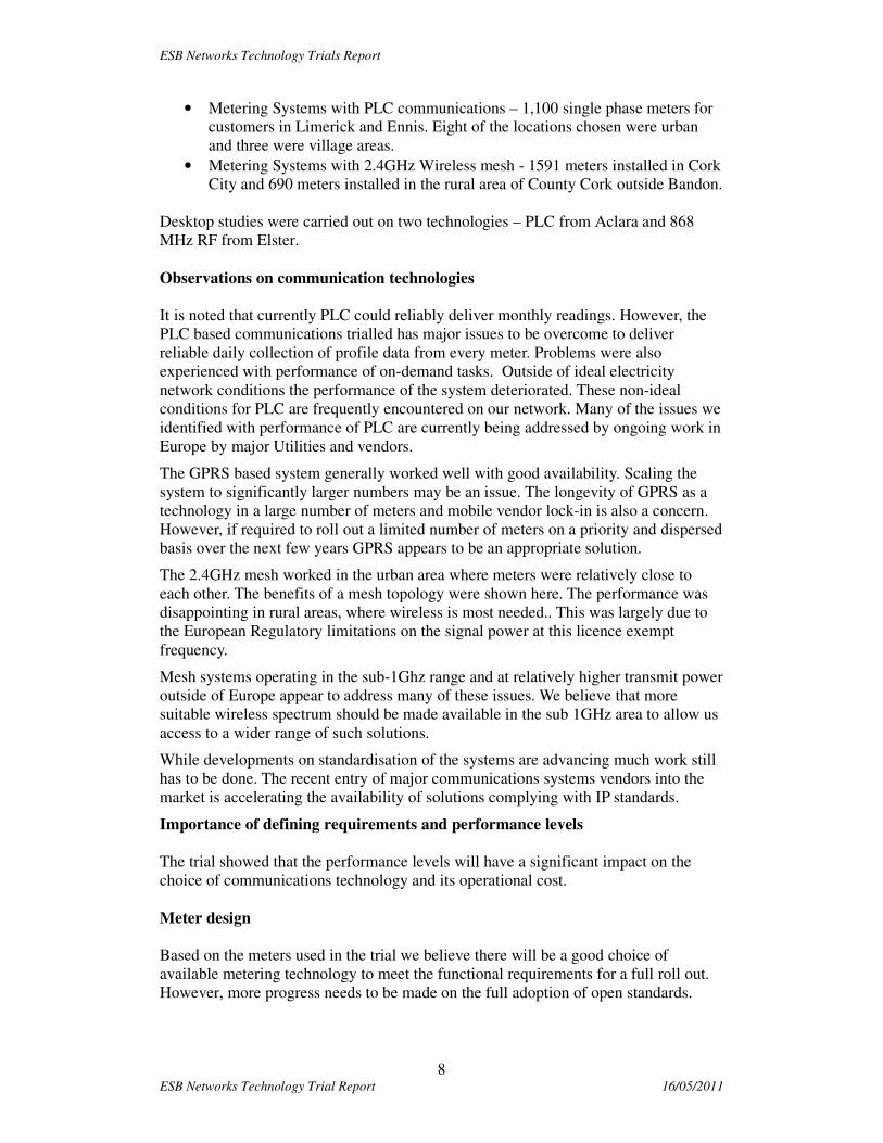
• Metering Systems with PLC communications – 1,100 single phase meters for
customers in Limerick and Ennis. Eight of the locations chosen were urban
and three were village areas.
• Metering Systems with 2.4GHz Wireless mesh - 1591 meters installed in Cork
City and 690 meters installed in the rural area of County Cork outside Bandon.
Desktop studies were carried out on two technologies – PLC from Aclara and 868
MHz RF from Elster.
Observations on communication technologies
It is noted that currently PLC could reliably deliver monthly readings. However, the
PLC based communications trialled has major issues to be overcome to deliver
reliable daily collection of profile data from every meter. Problems were also
experienced with performance of on-demand tasks. Outside of ideal electricity
network conditions the performance of the system deteriorated. These non-ideal
conditions for PLC are frequently encountered on our network. Many of the issues we
identified with performance of PLC are currently being addressed by ongoing work in
Europe by major Utilities and vendors.
The GPRS based system generally worked well with good availability. Scaling the
system to significantly larger numbers may be an issue. The longevity of GPRS as a
technology in a large number of meters and mobile vendor lock-in is also a concern.
However, if required to roll out a limited number of meters on a priority and dispersed
basis over the next few years GPRS appears to be an appropriate solution.
The 2.4GHz mesh worked in the urban area where meters were relatively close to
each other. The benefits of a mesh topology were shown here. The performance was
disappointing in rural areas, where wireless is most needed.. This was largely due to
the European Regulatory limitations on the signal power at this licence exempt
frequency.
Mesh systems operating in the sub-1Ghz range and at relatively higher transmit power
outside of Europe appear to address many of these issues. We believe that more
suitable wireless spectrum should be made available in the sub 1GHz area to allow us
access to a wider range of such solutions.
While developments on standardisation of the systems are advancing much work still
has to be done. The recent entry of major communications systems vendors into the
market is accelerating the availability of solutions complying with IP standards.
Importance of defining requirements and performance levels
The trial showed that the performance levels will have a significant impact on the
choice of communications technology and its operational cost.
Meter design
Based on the meters used in the trial we believe there will be a good choice of
available metering technology to meet the functional requirements for a full roll out.
However, more progress needs to be made on the full adoption of open standards.
ESB Networks Technology Trials Report
9 ESB Networks Technology Trial Report 16/05/2011
Installation work
For the half of our customers with indoor meters the management of access to install
the smart meter was a key deployment issue. The time spent with the vendors to
ensure that the meter install process was ‘plug and play’ was of great benefit.
However, it is to be noted that technical issues were encountered in at least 3% of
installations which required a lot more work than simply installing the smart meters
in. This would have to be factored into the costing and planning of a full roll out.
Testing
The trial demonstrated the importance of a comprehensive testing strategy. Sufficient
time must be allowed for soak testing of meters and devices in the field. Major
security testing should also take place at this time.
Security and data protection
It is essential that all data collected and processed via the smart metering
infrastructure be handled securely and that customer privacy is safeguarded at all
times. The security associated with the solutions used in the trials were deemed fit for
purpose. The trial included encryption of data and full compliance with Data
Protection Legislation. As a general rule for a full roll out there will have to be an
increased focus on areas such as
• standards based security solutions leveraging security protocols deployed in
other sensitive industries such as internet banking, telecomms and defence
• robust mechanisms for protecting the integrity of the smart metering network
• secure hardware manufacturing processes and software development lifecycles
• a robust, secure and speedy process to provide firmware upgrades to meters
and devices in the field.
Timetable
Smart metering is a complex program. The experience in the trial and that of other
utilities who have undertaken smart metering deployment reinforces this view. The
program can be up to 7 years duration with almost half the time required before full
deployment. The key phases these phases include:
• Definition of requirements, design, planning, specification and procurement.
At the end of this phase we will have selected the solutions.
• Design test and installation of IT systems including integration to meters.
• Roll out of comms. infrastructure and installation of meters and other devices.
Based on the above assumptions on the timetable we could be deciding in late 2012
on the full roll out solution.
Further work
The recent entry of major communications systems vendors into the market is
accelerating the availability of solutions complying with IP standards which will be of
benefit. It is important that we build on the learning from the technology trials and
continue to be involved in examining other potential solutions as they arise

ESB Networks Technology Trials Report
10 ESB Networks Technology Trial Report 16/05/2011
2 Introduction
2.1 Purpose of document
This document contains ESB Networks key learning’s from the Smart Metering
Technology Trial.
2.2 Background
In 2007 ESB Networks committed to CER to run a smart metering pilot. This pilot
was deemed a necessary step in developing an understanding of smart metering.
The project was split between the Customer Behavior Trial (CBT) and Technology
trials. ESB Networks agreed the plan and timetable with CER. These trials were
incorporated in the CER’s Program for Phase One of the National Smart Metering
Plan.
The technologies selected from those offered during the Smart Metering Pilot Project
procurement allowed ESB Networks to ensure that powerline, wireless LAN and
point to point solutions were trialled. Ireland has a unique population settlement
pattern and as a consequence the scale and nature of the resultant electricity
distribution system means that we have challenges designing and implementing Smart
Metering which are not as significant for other European countries.
ESB Networks’ goals for the Technology Pilot were:
• To set up a pilot advanced metering infrastructure; composed of smart meters,
communications infrastructure and head end collection software.
• Assess communications solutions
• To ascertain if smart metering technology has sufficient functionality,
reliability and performance levels to meet core business requirements
• To quantify the technical issues faced in the customers premises
• To embed organizational knowledge on smart metering across the range of
business and technology dimensions involved.
ESB Networks Technology Trials Report
11 ESB Networks Technology Trial Report 16/05/2011
3 Technologies Selected for Trial
The Procurement process for metering systems commenced with an OJEU notice at
the end of 2007, the specification for the trial metering systems was produced and the
metering procurement process completed in mid 2008. Based on this process and on
the offers submitted, technologies were selected by ESB Networks for the trial.
The Customer Behaviour Trial (CBT) was initially prioritised because of its scale and
critical timetable. This trial was also a great learning opportunity in terms of smart
metering systems design, testing, delivery and deployment. It also provided us with an
excellent opportunity to assess GPRS.
In addition to the CBT, ESB Networks finalised the detailed project scope of the
Technology Trials with each of the selected Suppliers. We were conscious of the need
to minimise the cost and given that this was a trial, where possible we wanted to avoid
major design, development and associated testing work. It is important to understand
that the communications technologies were selected in 2008 based on what was
offered at that time. Our objective was to see as many as possible of the major
communications technology groups represented in the trials.
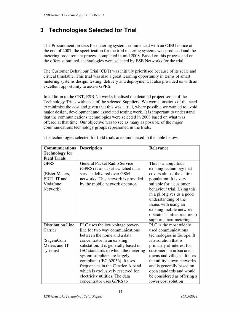
The technologies selected for field trials are summarised in the table below:
Communications
Technology for
Field Trials
Description Relevance
GPRS
(Elster Meters,
EICT IT and
Vodafone
Network)
General Packet Radio Service
(GPRS) is a packet-switched data
service delivered over GSM
networks. This network is provided
by the mobile network operator.
This is a ubiquitous
existing technology that
covers almost the entire
population. It is very
suitable for a customer
behaviour trial. Using this
in a pilot gives us a good
understanding of the
issues with using an
existing mobile network
operator’s infrastructure to
support smart metering.
Distribution Line
Carrier
(SagemCom
Meters and IT
systems)
PLC uses the low voltage power-
line for two way communications
between the home and a data
concentrator in an existing
substation. It is generally based on
IEC standards to which the metering
system suppliers are largely
compliant (IEC 62056). It uses
frequencies in the Cenelec A band
which is exclusively reserved for
electricity utilities. The data
concentrator uses GPRS to
PLC is the most widely
used communications
technologies in Europe. It
is a solution that is
primarily of interest for
customers in urban areas,
towns and villages. It uses
the utility’s own networks
and is generally based on
open standards and would
be considered as offering a
lower cost solution

ESB Networks Technology Trials Report
12 ESB Networks Technology Trial Report 16/05/2011
communicate back and forth with
the IT systems.
Wireless Mesh at
2.4GHz
(Trilliant Comms.
and IT with
Iskrameko
meters)
Mesh radio is a private radio
network technology for
communicating with meters, which
uses meters as repeaters in a mesh
configuration. The meter collector
receives and transmits signals to
meters which, in turn, pass these
signals on to other meters. The
frequency used is generally licence
exempt. In the case of this trial we
are using the licence exempt
2.4GHz spectrum. Wireless mesh
tends to be a proprietary offering.
Wireless mesh is favoured
for smart metering
solutions in US and
Australia. While the
spectrum generally used
for these deployments is in
the 900MHz range and
therefore not useable in
Europe, the solution
chosen is in the 2.4GHz
range which is available
for use in Europe. Given
the large number of
customers in Ireland
(approx. 40%) outside the
urban areas not reachable
by conventional PLC it is
important to look at the
use of wireless and how it
performs in Irish
conditions
Based on the technologies offered in procurement in 2008 it was also decided to carry
out small desktop studies on two of the other technologies offered.
Communications
for Desktop
Study
Description Relevance
Power-line
Carrier
(Aclara)
This technology uses the power line
to the home to carry a low
bandwidth signal. Special equipment
is installed in the 38kV station
Signals are created by producing a
unique pattern of current pulses in
the field devices and detecting those
pulses in the substation. The
solution is proprietary.
The technology might
offer an option for rural
areas with low population
density, depending on the
performance requirements
for a full roll out.
Wireless Tree at
868MHz
(Elster\Coronis)
This is a private radio network
technology for communicating with
meters, which uses meters as
repeaters in a tree configuration. The
meter Data Collector receives and
transmits signals to and from meters
which, in turn, pass these signals
either directly or via repeaters. The
This solution is currently
used in Europe for water
metering. We wished to
examine if this solution
could be used for rural
customers.

ESB Networks Technology Trials Report
13 ESB Networks Technology Trial Report 16/05/2011
frequency used is generally un-
licensed. In the case of this trial we
are using the un-licensed 868MHz
spectrum.
WAN Technology
For the purposes of the trial GPRS was designated as the WAN technology for all the
LAN technologies being trialled. This was done to facilitate flexibility and speed of
deployment. The use of this mature, well understood, standards based, ubiquitous
technology for the WAN, common to all the LAN technologies, allowed the project to
concentrate its efforts on designing, deploying and assessing the more complex and
less mature LAN technologies eliminating many possible areas of uncertainty. It
should not be assumed that GPRS would be used as the WAN for a full roll out.
ESB Networks Technology Trials Report
14 ESB Networks Technology Trial Report 16/05/2011
4 Delivery of the Trials
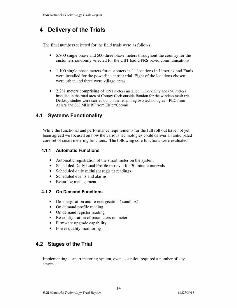
The final numbers selected for the field trials were as follows:
• 5,800 single phase and 500 three phase meters throughout the country for the
customers randomly selected for the CBT had GPRS based communications.
• 1,100 single phase meters for customers in 11 locations in Limerick and Ennis
were installed for the powerline carrier trial. Eight of the locations chosen
were urban and three were village areas.
• 2,281 meters comprising of 1591 meters installed in Cork City and 690 meters
installed in the rural area of County Cork outside Bandon for the wireless mesh trial.
Desktop studies were carried out on the remaining two technologies – PLC from
Aclara and 868 MHz RF from Elster/Coronis.
4.1 Systems Functionality
While the functional and performance requirements for the full roll out have not yet
been agreed we focused on how the various technologies could deliver an anticipated
core set of smart metering functions. The following core functions were evaluated:
4.1.1 Automatic Functions
• Automatic registration of the smart meter on the system
• Scheduled Daily Load Profile retrieval for 30 minute intervals
• Scheduled daily midnight register readings
• Scheduled events and alarms
• Event log management
4.1.2 On Demand Functions
• De-energisation and re-energisation ( sandbox)
• On demand profile reading
• On demand register reading
• Re-configuration of parameters on meter
• Firmware upgrade capability
• Power quality monitoring
4.2 Stages of the Trial
Implementing a smart metering system, even as a pilot, required a number of key
stages

ESB Networks Technology Trials Report
15 ESB Networks Technology Trial Report 16/05/2011
4.2.1 Stage 1 - Design Stage
A design phase was carried out to agree areas such as:
• Overall solution architecture,
• Functionality of the system
• Communications performance model
• Data model
• Meter type and schema
• Security architecture
• Documentation and implementation plan.
• User Manuals and system support
.
4.2.2 Stage 2 - Testing and Quality Assurance stage
There were multiple phases of testing designed to complete this critical stage of the
technology trial. The phases of testing included:
• Factory Unit Testing (Meters) - demonstrated that the meter meets the
functional requirements
• Factory System Testing (Full Metering System) - demonstrated the
functionality of the complete metering system, including the MDMS/Head
end, Communications devices and their integration with sample meters.
• Sandbox System Integration Testing (Metering System) - These tests were
carried out prior to deployment of the system in a ‘Live Environment’ in ESB.
The test was conducted on a complete, fully functioning system including the
head end fully configured and running on the ESB Networks smart metering
project Test environment, communications devices installed and
communicating over the ESB WAN and with an adequate number of meters,
installed in representative locations, needed to carry out the tests connected to
the System.

ESB Networks Technology Trials Report
16 ESB Networks Technology Trial Report 16/05/2011
Sandbox test environment (panel)
• Field Soak Test (Metering System) – The soak test involves installing a small
number of meters in a production environment and verifying that they operate
correctly over a reasonable period of time . The intention is to identify any
type faults which might require rectification in the field before installing large
amounts of the equipment
• Site acceptance, stress and volume testing (Metering System)
All testing for each of these stages were carried out jointly between ESB Networks
and the Vendor.
4.2.3 Stage 3 - Deployment, upgrades and enhancements of systems in the field.
The stages in the deployment process were:
• Deployment Planning and Area selection – This involved selection of the trial
areas and the network, meter position and customer types.
• Customer information - This consisted of written communications with all
customers in the trial areas and responding to their queries,
• Pilot Deployment – This process was designed to test (i) ESB Networks
deployment processes for the different types of meters and (ii) the
performance of the different communications technologies on real networks,
to identify any defects / enhancements required before proceeding with the full
deployment.
ESB Networks Technology Trials Report
17 ESB Networks Technology Trial Report 16/05/2011
• Communications models were developed to predict performance and to
identify the best places to locate communications devices.
• Mass Deployment- This process was the installation of the customer meters.
This work was carried out within the normal ESB meter replacement
processes
• Upgrades / fixes for defects and issues discovered in the field.
4.2.4 Stage 4 – Measurement and Evaluation
Once ESB Networks had deployed the meters and baselined any subsequent firmware
upgrades or other fixes for various defects that were identified in the field we
commenced the measurement and evaluation phase. During this phase the
performance of the system in relation to the various functionalities was measured.
The trial areas were chosen with a view to developing an understanding of how the
various technologies would perform in different scenarios. These scenarios explored
also related to the technology under evaluation.
These scenarios included:
• Urban / Rural locations
• Overhead / underground network
• Indoor / Outdoor / Centralised Meter Position
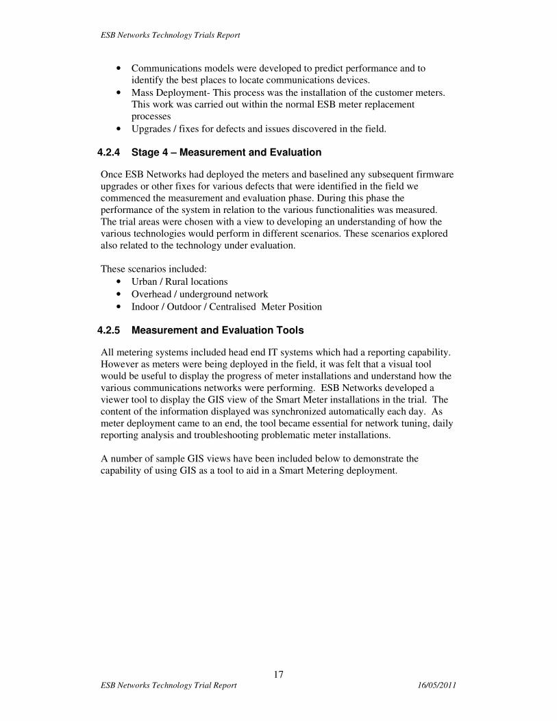
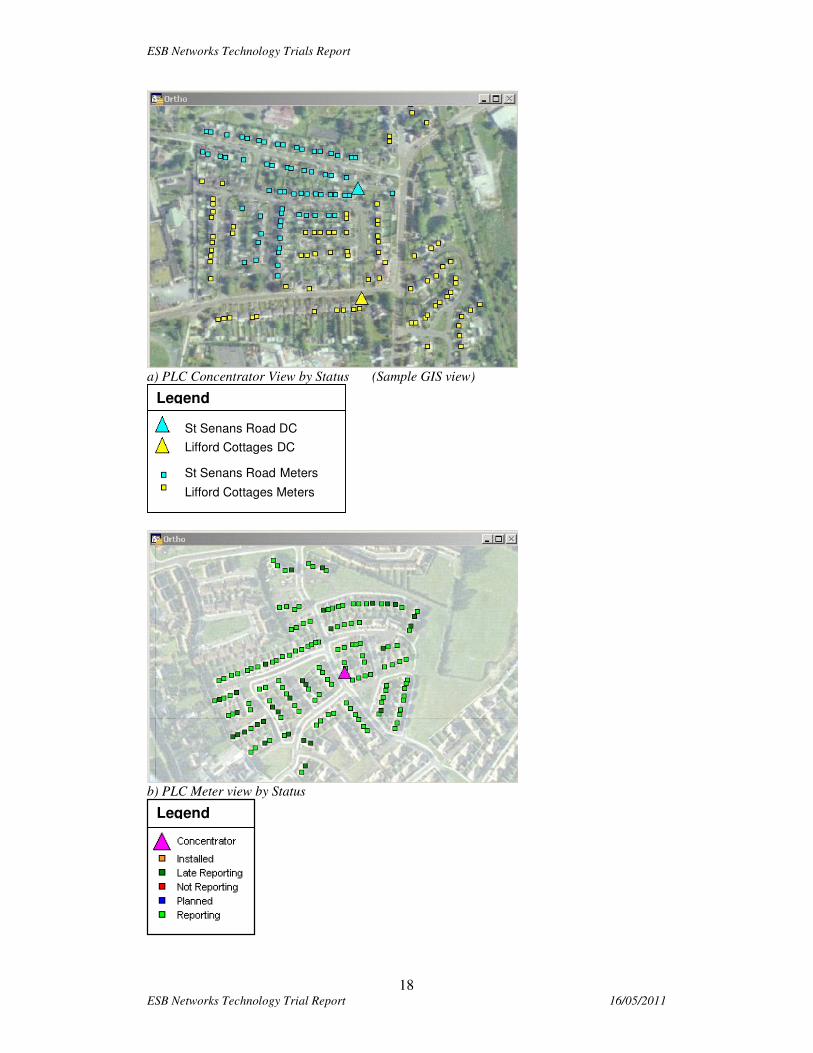
4.2.5 Measurement and Evaluation Tools
All metering systems included head end IT systems which had a reporting capability.
However as meters were being deployed in the field, it was felt that a visual tool
would be useful to display the progress of meter installations and understand how the
various communications networks were performing. ESB Networks developed a
viewer tool to display the GIS view of the Smart Meter installations in the trial. The
content of the information displayed was synchronized automatically each day. As
meter deployment came to an end, the tool became essential for network tuning, daily
reporting analysis and troubleshooting problematic meter installations.
A number of sample GIS views have been included below to demonstrate the
capability of using GIS as a tool to aid in a Smart Metering deployment.
ESB Networks Technology Trials Report
18 ESB Networks Technology Trial Report 16/05/2011
a) PLC Concentrator View by Status (Sample GIS view)
b) PLC Meter view by Status
St Senans Road DC
Lifford Cottages DC
St Senans Road Meters
Lifford Cottages Meters
Legend
Legend

ESB Networks Technology Trials Report
19 ESB Networks Technology Trial Report 16/05/2011
5 Observations and findings from the Technology Trials
5.1 Distribution Line Carrier Trial
5.1.1 Overview of Technology:
The Power Line Carrier (PLC) Technology Trial Project was carried out with Sagem,
in the period April 2009 – June 2010. The Trial employed 1st generation PLC
technology which has been widely used for the past 10 years. The principle of PLC is
that a high frequency information signal is added (‘modulated’) to the 50Hz power
flow signal (‘carrier signal’) at the sending end and is removed at the receiving end
(‘de-modulated’), as shown in the following diagram:
The PLC product complies with IEC open standards. At the physical level, it uses a
modulation scheme called S-FSK (Spread/Spaced Frequency Shift Key) which is
defined by an IEC standard. This scheme uses a pair of discrete frequencies to
transmit binary information. These frequencies are in the CENELEC A Band (9 kHz
to which is reserved for Utilities Communication. Sagem employ a fixed data
communication rate of 1200 bps. The communication protocol is defined by IEC in
the DLMS/COSEM series of standards. The standards allow suppliers flexibility on
how they implement certain functions. However, interoperability could be enforced
by a utility defining the exact implementation schemes to be employed.
The Timescale for the Trial was:
• System Design & Test, IT Infrastructure Deployment - Started in April 2009
and completed in July 2009
• Field Deployment - Started in August 5th 2009 and completed in January
2010
• System Commissioning - Started in January 2010 and Completed in May
2010
• Measurement & Evaluation - Started in May 2010 and completed in August
2010
ESB Networks Technology Trials Report
20 ESB Networks Technology Trial Report 16/05/2011
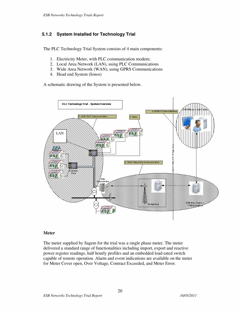
5.1.2 System Installed for Technology Trial
The PLC Technology Trial System consists of 4 main components:
1. Electricity Meter, with PLC communication modem;
2. Local Area Network (LAN), using PLC Communications
3. Wide Area Network (WAN), using GPRS Communications
4. Head end System (Ionos)
A schematic drawing of the System is presented below.
Meter
The meter supplied by Sagem for the trial was a single phase meter. The meter
delivered a standard range of functionalities including import, export and reactive
power register readings, half hourly profiles and an embedded load-rated switch
capable of remote operation. Alarm and event indications are available on the meter
for Meter Cover open, Over Voltage, Contract Exceeded, and Meter Error.
LAN
ESB Networks Technology Trials Report
21 ESB Networks Technology Trial Report 16/05/2011
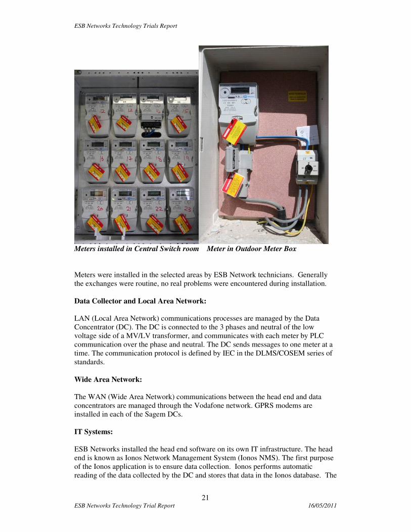
Meters installed in Central Switch room Meter in Outdoor Meter Box
Meters were installed in the selected areas by ESB Network technicians. Generally
the exchanges were routine, no real problems were encountered during installation.
Data Collector and Local Area Network:
LAN (Local Area Network) communications processes are managed by the Data
Concentrator (DC). The DC is connected to the 3 phases and neutral of the low
voltage side of a MV/LV transformer, and communicates with each meter by PLC
communication over the phase and neutral. The DC sends messages to one meter at a
time. The communication protocol is defined by IEC in the DLMS/COSEM series of
standards.
Wide Area Network:
The WAN (Wide Area Network) communications between the head end and data
concentrators are managed through the Vodafone network. GPRS modems are
installed in each of the Sagem DCs.
IT Systems:
ESB Networks installed the head end software on its own IT infrastructure. The head
end is known as Ionos Network Management System (Ionos NMS). The first purpose
of the Ionos application is to ensure data collection. Ionos performs automatic
reading of the data collected by the DC and stores that data in the Ionos database. The

ESB Networks Technology Trials Report
22 ESB Networks Technology Trial Report 16/05/2011
data is then available for processing by ESB Networks. Custom reporting tools were
developed by the project team to query the head end metering data repository to
provide reports on the performance of the Metering System.
Implementation and Deployment:
The PLC trial was run on 11 low voltage networks in the Limerick/Ennis area,
containing a total of 1257 customers. Smart meters were installed in 1057 customer
premises. Meters were not installed in the remaining customer premises because:
• Only standard single phase customers were included in the trial
• The deployment relied on access to customer premises to carryout the meter
replacement; in modern estates with outside meter boxes 100% access was
achieved, but for older estates the figure was close to 80%.
Following commissioning, a ‘Measurement and Evaluation’ phase examined the
functional performance delivery of the system, focussing on the time required to read
the previous day’s interval data from every meter, and the time taken and success rate
of ‘on-demand’ actions.
The pictures below outline a variety of the connection types used during the course of
the pilot, including connections to overhead and underground network.
Sub Station and OH network pole at Lifford Cottage DC at Lifford Cottage Unit Sub

ESB Networks Technology Trials Report
23 ESB Networks Technology Trial Report 16/05/2011
Annacotty North: DC connected to OH Network (Pole Mounted)
:
Data Concentrator installed in Bru Na Sionna
Data Concentrator
ESB Networks Technology Trials Report
24 ESB Networks Technology Trial Report 16/05/2011
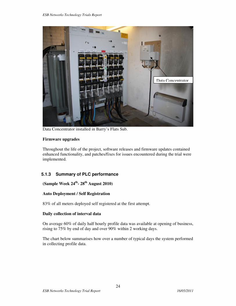
Data Concentrator installed in Barry’s Flats Sub.
Firmware upgrades
Throughout the life of the project, software releases and firmware updates contained
enhanced functionality, and patches/fixes for issues encountered during the trial were
implemented.
5.1.3 Summary of PLC performance
(Sample Week 24th
- 28th
August 2010)
Auto Deployment / Self Registration
83% of all meters deployed self registered at the first attempt.
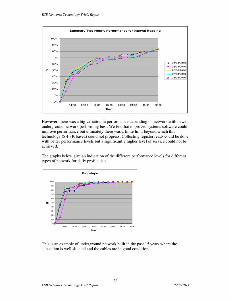
Daily collection of interval data
On average 60% of daily half hourly profile data was available at opening of business,
rising to 75% by end of day and over 90% within 2 working days.
The chart below summarises how over a number of typical days the system performed
in collecting profile data.
Data Concentrator
ESB Networks Technology Trials Report
25 ESB Networks Technology Trial Report 16/05/2011
Summary Two Hourly Performance for Interval Reading
0%
10%
20%
30%
40%
50%
60%
70%
80%
90%
100%
04:00 08:00 12:00 16:00 20:00 24:00 40:00 72:00
Time
%
24/08/2010
25/08/2010
26/08/2010
27/08/2010
28/08/2010
However, there was a big variation in performance depending on network with newer
underground network performing best. We felt that improved systems software could
improve performance but ultimately there was a finite limit beyond which this
technology (S-FSK based) could not progress. Collecting register reads could be done
with better performance levels but a significantly higher level of service could not be
achieved.
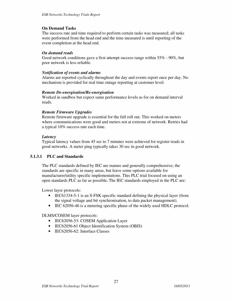
The graphs below give an indication of the different performance levels for different
types of network for daily profile data.
Dooradoyle
0%
10%
20%
30%
40%
50%
60%
70%
80%
90%
100%
04:00 08:00 12:00 16:00 20:00 24:00 40:00 72:00
Ti me
This is an example of underground network built in the past 15 years where the
substation is well situated and the cables are in good condition.

ESB Networks Technology Trials Report
26 ESB Networks Technology Trial Report 16/05/2011
Corrib Drive
0%
10%
20%
30%
40%
50%
60%
70%
80%
90%
100%
04:00 08:00 12:00 16:00 20:00 24:00 40:00 72:00
Ti me
Corrib Drive is an example of older underground network with multiple joints in the
cables and small service cables to customers.
Cappagh Road
0%
10%
20%
30%
40%
50%
60%
70%
80%
90%
100%
04:00 08:00 12:00 16:00 20:00 24:00 40:00 72:00
Ti me
Cappagh Road is an example of mixed network which has substantial new sections.
Annacotty
0%
10%
20%
30%
40%
50%
60%
70%
80%
90%
100%
04:00 08:00 12:00 16:00 20:00 24:00 40:00 72:00
Ti me
Annacotty is an example of older overhead network.
ESB Networks Technology Trials Report
27 ESB Networks Technology Trial Report 16/05/2011
On Demand Tasks
The success rate and time required to perform certain tasks was measured; all tasks
were performed from the head end and the time measured is until reporting of the
event completion at the head end.
On demand reads Good network conditions gave a first attempt success range within 55% - 90%, but
poor network is less reliable.
Notification of events and alarms
Alarms are reported cyclically throughout the day and events report once per day. No
mechanism is provided for real time outage reporting at customer level.
Remote De-energisation/Re-energisation Worked in sandbox but expect same performance levels as for on demand interval
reads.
Remote Firmware Upgrades Remote firmware upgrade is essential for the full roll out. This worked on meters
where communications were good and meters not at extreme of network. Retries had
a typical 10% success rate each time.
Latency Typical latency values from 45 sec to 7 minutes were achieved for register reads in
good networks. A meter ping typically takes 30 sec in good network.
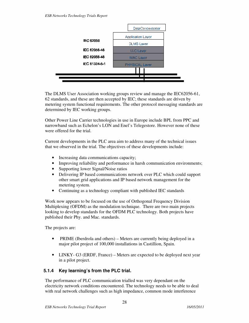
5.1.3.1 PLC and Standards
The PLC standards defined by IEC are mature and generally comprehensive; the
standards are specific in many areas, but leave some options available for
manufacturer/utility specific implementations. This PLC trial focused on using an
open standards PLC as far as possible. The IEC standards employed in the PLC are:
Lower layer protocols:
• IEC61334-5-1 is an S-FSK specific standard defining the physical layer (from
the signal voltage and bit synchronisation, to data packet management).
• IEC 62056-46 is a metering specific phase of the widely used HDLC protocol.
DLMS/COSEM layer protocols:
• IEC62056-53: COSEM Application Layer
• IEC62056-61 Object Identification System (OBIS)
• IEC62056-62: Interface Classes
ESB Networks Technology Trials Report
28 ESB Networks Technology Trial Report 16/05/2011
The DLMS User Association working groups review and manage the IEC62056-61,
62 standards, and these are then accepted by IEC; these standards are driven by
metering system functional requirements. The other protocol messaging standards are
determined by IEC working groups.
Other Power Line Carrier technologies in use in Europe include BPL from PPC and
narrowband such as Echelon’s LON and Enel’s Telegestore. However none of these
were offered for the trial.
Current developments in the PLC area aim to address many of the technical issues
that we observed in the trial. The objectives of these developments include:
• Increasing data communications capacity;
• Improving reliability and performance in harsh communication environments;
• Supporting lower Signal/Noise ratios
• Delivering IP based communications network over PLC which could support
other smart grid applications and IP based network management for the
metering system.
• Continuing as a technology compliant with published IEC standards
Work now appears to be focused on the use of Orthogonal Frequency Division
Multiplexing (OFDM) as the modulation technique. There are two main projects
looking to develop standards for the OFDM PLC technology. Both projects have
published their Phy. and Mac. standards.
The projects are:
• PRIME (Iberdrola and others) – Meters are currently being deployed in a
major pilot project of 100,000 installations in Castillion, Spain.
• LINKY- G3 (ERDF, France) – Meters are expected to be deployed next year
in a pilot project.
5.1.4 Key learning’s from the PLC trial.
The performance of PLC communication trialled was very dependant on the
electricity network conditions encountered. The technology needs to be able to deal
with real network challenges such as high impedance, common mode interference
PHYSICAL Layer MAC Layer LLC Layer DLMS Layer Application Layer Electrical Network PH1 PH2
DataConcentrator IEC 61334IEC 61334IEC 61334IEC 61334----5555----1111 IEC 62056IEC 62056IEC 62056IEC 62056 IEC 62056IEC 62056IEC 62056IEC 62056----46464646 IEC 62056IEC 62056IEC 62056IEC 62056----46464646
ESB Networks Technology Trials Report
29 ESB Networks Technology Trial Report 16/05/2011
between adjacent LV network areas, and other difficult and noisy operating
environments
The service levels achievable in the best LV network were 90% of interval data
delivered after 18 hours and 100% of interval data delivered after 48 hours.
The current generation of PLC trialled would not meet performance requirements of
99% next day profile data. Higher service levels would be achieved if monthly
register read were the only read requirement, rather than 48 daily intervals reads.
While firmware upgrades were successfully carried out, they will not work well with
poor communication network conditions.
PLC exists on utility owned spectrum, is a technology which can be based on
published standards and likely has the lowest total cost of ownership
PLC is very much the technology of choice for most major European smart metering
deployments. The ongoing developments in moving to next generation PLC based on
OFDM will have to be watched closely. These newer PLC technologies should allow
implementation of IP networking to meters.. Success in these developments would
support the use of next generation PLC as the most suitable technology for urban
areas.

ESB Networks Technology Trials Report
30 ESB Networks Technology Trial Report 16/05/2011
5.2 2.4GHz RF Mesh Trial
5.2.1 Overview of the technology
RF (Radio Frequency) Mesh is a radio network technology for communicating with
meters, which uses meters as repeaters in a mesh configuration. The majority of
systems being deployed in North America and Australia use this family of
technologies. Trilliant are one of a number of RF Mesh vendors. Trilliant offered a
system which could operate in the licence exempt spectrum in Europe. Most of the
others operate at 900MHz, which is not licence exempt for use in Ireland.
The Trilliant LAN operates in the 2.4GHz ISM band (Band 2.400 – 2.483 GHz). This
band is licence exempt but subject to guidelines issued by ETSI. The radio EIRP had
to be limited to 100mW to comply with EU standards. In North America EIRP of up
to 1 Watt is permissible. The physical radios utilise standard IEEE802.15.4-compliant
radio chipsets.
The meter itself was a DLMS/COSEM meter developed for the European market.
Several key issues needed to be addressed for the solution to work. These included the
integration of the Iskraemeko meter with the Trilliant networking technology and the
optimisation of the system to work under the constraints of the European
communications regulatory regime.
5.2.2 Radio Issues
2.4 GHz is a licence exempt frequency. This means that any equipment manufacturer
may use it provided the equipment adheres to the relevant EU regulations governing
transmission power and duty cycle. Part of the RF trial involved evaluating common
2.4GHz devices on the market in Ireland to assess the likelihood and impact of
interference both caused, and experienced, by the system.
5.2.3 Timescales
The Timescale for the Trial was:
• System Design & Test, IT Infrastructure Deployment - Completed in Sept
2009
• Field Deployment - Started in October 2009 and completed in January 2010.
This was based on release 1.
• RF Planning, Deployment and Tuning – Started in January and completed in
March 2010
• Upgrade to DLMS/COSEM release testing and implementation – January to
April 2010
• System Commissioning - Started in January 2010 and Completed in May
2010
• Measurement & Evaluation - Started in June 2010 and completed in August
2010

ESB Networks Technology Trials Report
31 ESB Networks Technology Trial Report 16/05/2011
5.2.4 System Installed for Technology Trial
The key components are the meter including the comms module, the repeaters, the
MeshGate (Collector/Data Concentrator), the WAN modem and SerViewCom (the
head end). These components and their functions are described in more detail below.
Meter
The meter is comprised of two major components, the measuring device itself and the
network component. Iskraemeko
The meter is a Single-phase, Whole Current (WC) rated meter. The meter is an IEC
meter that utilizes DLMS/COSEM as its native protocol.

ESB Networks Technology Trials Report
32 ESB Networks Technology Trial Report 16/05/2011
Iskraemeco meter,
The Comms module provides the interface between the meter and the SecureMesh
network. It has a 2.4GHz RF chip and antenna. It reads the information from the
meter and packages it for transmission onto the network. It is responsible for ensuring
reliable communication between the meter and the head end either directly or via
intermediate mesh nodes. It is also responsible for relaying data from other nodes
onwards through the network to the head end.
Repeater:
The Repeater serves as an intermediate wireless node to relay messages to and from
the meters. Its function is to fill in gaps in the mesh allowing isolated meters or
groups of meters to mesh in with the network. These are typically mains powered
devices mounted on poles.
Repeater
Enclosure
Data Collector (SecureMesh Gateway)
The collector serves as an access point for meters. Each collector supports
communications to and from the head end for the meters with which it communicates.
It provides local data storage and minimises WAN communications requirements by
compressing the data.

ESB Networks Technology Trials Report
33 ESB Networks Technology Trial Report 16/05/2011
SecureMesh Gateway and Enclosure
The collector is typically pole mounted; collects data from meters and forwards this
data over the WAN to the head end using its internal GPRS/3G modem.
Wide Area Network Architecture (WAN)
The WAN (Wide Area Network) communications between the head end and data
concentrators are managed through the Vodafone network. GPRS modems are
installed in each of the Trilliant data collectors.
IT systems
SerViewCom is the head end system provided by Trilliant which enables
communications with the meters. It also allows for the storage of data together with a
user interface. This was installed on ESB Networks IT systems.
5.2.5 Implementation and Deployment
Two trial locations, Inishannon in rural Cork and an area of Cork City, were selected
to represent environments typical of those which would be encountered in the Irish
context. These areas incorporated a mix of sparse and dense population, heavy
foliage, hilly terrain, ribbon development, multi dwelling buildings, terraced houses
and semi urban estates.
The numbers of meters installed were 690 in the rural area and 1,591 in the urban
area. The large number of meters installed was determined by the need to ensure that
an effective mesh could be formed and that observation of scenarios could be
performed.

ESB Networks Technology Trials Report
34 ESB Networks Technology Trial Report 16/05/2011
One of the major issues we faced was the work required to integrate the comms
module with the meter. The meter itself had a high level of functionality. It captures
time of use, profile data and events and alarms. The challenge was to access as much
of this information as possible within the timeframe of the trial.
The implementation was split into two separate and distinct phases. The key
objectives for the first phase of implementation were the integration of the comms
module into the meter and provision of basic register and derived profile data to the
IT systems. The second phase involved increasing the software interfaces between
the comms module and the meter to make available actual profile data, and remaining
events and alarms information from the meter. Both development stages required
significant testing effort.
For the first phase testing went well in all respects in the Sandbox. All expected
functionality was delivered and system functioned well. On the basis of the success of
the testing it was decided to proceed with the deployment of meters in the field.
Unfortunately, subsequent testing of phase 2 required a number of iterations.
The RF planning stage included a field survey to ensure that the locations identified
for network hardware are suitable and have clear RF propagation.
Based on network designs developed by network planning engineers, collectors were
installed at strategic locations in both areas. As is usual with this type of technology a
tuning exercise was carried out to fill gaps in coverage and optimise performance.
Initial results for phase 1 were encouraging in the urban area; however the rural area
results were disappointing. A review of the trial areas and the installed meters was
carried out at this point.
The performance of the Mesh in the rural area was investigated. The vendor provided
a number of replacement meters with an enhanced antenna and these were tested in
the field. These meters lead to improved performances in some cases. The antenna is
part of the meter and therefore resolving this problem involves replacing the meter.
Phase 2 of the product was implemented later on by means of firmware upgrade while
Phase 2 increased the system functionality; it had very little noticeable impact on the
performance of the rural trial. A number of attempts were made to rectify this issue.
ESB Networks Technology Trials Report
35 ESB Networks Technology Trial Report 16/05/2011
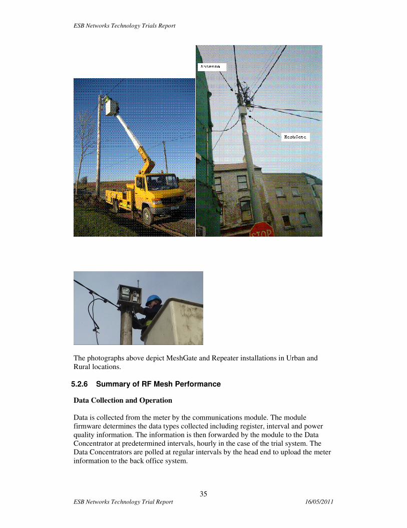
The photographs above depict MeshGate and Repeater installations in Urban and
Rural locations.
5.2.6 Summary of RF Mesh Performance
Data Collection and Operation
Data is collected from the meter by the communications module. The module
firmware determines the data types collected including register, interval and power
quality information. The information is then forwarded by the module to the Data
Concentrator at predetermined intervals, hourly in the case of the trial system. The
Data Concentrators are polled at regular intervals by the head end to upload the meter
information to the back office system.

ESB Networks Technology Trials Report
36 ESB Networks Technology Trial Report 16/05/2011
Auto Deployment / Self Registration - Good performance was achieved with 97%
deployed where signal was available
Daily collection of interval data and register data - Overall performance was
achieved on tuned network of 87% urban and 60% rural interval data next day 8.00
am. Additional repeaters, mesh-gates and enhanced antennae could bring performance
up to 95% overall. The graph below gives the information in relation to the
performance of tuned networks.
The graphs below show the performance at individual data collectors over a typical 5
day period
U r b a n
D a i l y O n -t i m e M e t e r s
0 %
1 0 %
2 0 %
3 0 %
4 0 %
5 0 %
6 0 %
7 0 %
8 0 %
9 0 %
1 0 0 %
2 6 / 0 8 / 2 0 1 0 2 7 / 0 8 / 2 0 1 0 2 8 / 0 8 / 2 0 1 0 2 9 / 0 8 / 2 0 1 0 3 0 / 0 8 / 2 0 1 0 3 1 / 0 8 /2 0 1 0
R u r a l
D a i l y O n -t im e M e t e r s
0 %
1 0 %
2 0 %
3 0 %
4 0 %
5 0 %
6 0 %
7 0 %
8 0 %
9 0 %
1 0 0 %
2 6 / 0 8 / 2 0 1 0 2 7 / 0 8 / 2 0 1 0 2 8 / 0 8 / 2 0 1 0 2 9 / 0 8 / 2 0 1 0 3 0 / 0 8 / 2 0 1 0 3 1 / 0 8 / 2 0 1 0

ESB Networks Technology Trials Report
37 ESB Networks Technology Trial Report 16/05/2011
The collector below (Tower Street) is an example of a data collector performance in
an urban area with outdoor meter boxes and higher density of dwellings.
.
Tower St
0%
10%
20%
30%
40%
50%
60%
70%
80%
90%
100%
08:00 08:30 12:00 18:00 24.00 48:00 72:00Time
25/08/2010
26/08/2010
27/08/2010
28/08/2010
29/08/2010
The graph below the performance of a data collector in a tuned network where most
meters are indoors
Nuns Walk
0%
10%
20%
30%
40%
50%
60%
70%
80%
90%
100%
08:00 08:30 12:00 18:00 24.00 48:00 72:00
Time
25/08/2010
26/08/2010
27/08/2010
28/08/2010
29/08/2010
On demand reads
As part of the evaluation, a series of tests were performed against the on-demand task
capabilities of the meters. The success rate achieved can reach 71% on the first poll
and rises to 89% for the third poll. The time to complete the read varied from 30 sec
to 60sec.

ESB Networks Technology Trials Report
38 ESB Networks Technology Trial Report 16/05/2011
Notification of events and alarms
Alarm and event notification is generally cyclical – events and alarms are received
hourly at the data concentrator and polled regularly from the head end.
Last gasp reporting is in real time and was actually measured in the sandbox
environment at 30 sec.
Remote operation This was tested in the Sandbox environment. It was observed that the success rate and
reliability of the commands was high, provided that the meter is reliably associated
with the Mesh.
Firmware Upgrades
The system proved successful in delivering upgrades to the comms module on the
meter. However, given the development involved, meter firmware upgrade capability
was not delivered as part of trial.
Approximately 85% of the meters had the firmware on their comms module
successfully upgraded. We also believe that the vast majority would eventually have
upgraded given sufficient time.
Latency
As an indication of system latency the average time taken for an on-demand
command to successfully conclude was measured to take between 30 and 60 seconds.
Geography and Terrain
The rural area chosen for the trial is typical of any Irish rural setting. It includes open
fields, hedgerows, tree lines, small wooded areas, walls, hills and valleys.
2.4GHz RF is essentially a line-of-sight technology. It doesn’t pass through hills or
bend around corners. Reflections are often necessary for links to form. In rural areas,
direct line-of-sight between meters is rarely available. Meters which were located in
valleys were generally unable to join the Mesh. This is in contrast to meters which
were on top of hills with line-of-sight to other meters; two or three instances were
observed where meters formed links of around 3km.
Difficult terrain can be overcome by the addition of Repeaters
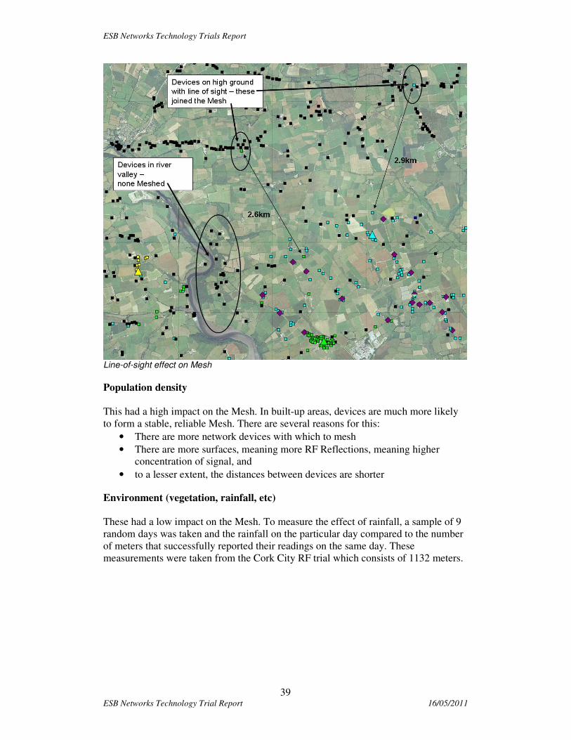
Distances between Mesh devices
Generally speaking the distances between devices was not a major factor in Mesh
formation. The other factors – terrain, population density and meter location – were
much more significant. The map below shows that links can form over long distances
if these other factors allow:
ESB Networks Technology Trials Report
39 ESB Networks Technology Trial Report 16/05/2011
Line-of-sight effect on Mesh
Population density
This had a high impact on the Mesh. In built-up areas, devices are much more likely
to form a stable, reliable Mesh. There are several reasons for this:
• There are more network devices with which to mesh
• There are more surfaces, meaning more RF Reflections, meaning higher
concentration of signal, and
• to a lesser extent, the distances between devices are shorter
Environment (vegetation, rainfall, etc)
These had a low impact on the Mesh. To measure the effect of rainfall, a sample of 9
random days was taken and the rainfall on the particular day compared to the number
of meters that successfully reported their readings on the same day. These
measurements were taken from the Cork City RF trial which consists of 1132 meters.

ESB Networks Technology Trials Report
40 ESB Networks Technology Trial Report 16/05/2011
From these measurements we can assume that typical rainfall has no impact on the
performance of RF Mesh.
The effect of vegetation was more difficult to evaluate. The meters were installed up
to December 2009 and the MeshGates shortly thereafter. The system at that time had
availability of around 90% within the tuned areas and with Version 1 functionality.
The availability of the system at the end of April - before the functionality Upgrades
began but after a period of warm weather and vegetation growth - was still at around
90%. Although the trial area was small, there was no noticeable drop in performance.
Effect of Rainfall on Mesh
0%
10%
20%
30%
40%
50%
60%
70%
80%
90%
100%
0 0 0 0 0.1 0.2 2.9 9 10.6
Rainfall mm
Mete
rs R
ep
ort
ing
Daily
Meters Reporting Daily

ESB Networks Technology Trials Report
41 ESB Networks Technology Trial Report 16/05/2011
Indoor vs. Outdoor meters Generally outdoor meters report more reliably than indoor meters. This is to be
expected. The following table and graph show the quantities of meters in the rural
tuned area, and whether they are located indoors or outdoors:
Rural Indoor vs Outdoor meter reporting
43
105
28
45
0% 20% 40% 60% 80% 100%
Indoor meters
Outdoor meters
Reporting
Not reporting
Note that in the case of outdoor meters, the orientation of the meter cabinet relative to
other meters determines whether the meter will mesh. Unfortunately this is entirely
random and impossible to predict or model without surveying each and every meter
location
Urban Indoor vs Outdoor meter reporting
466
273
414
20
0% 20% 40% 60% 80% 100%
Indoor meters
Outdoor meters
Reporting
Not reporting

ESB Networks Technology Trials Report
42 ESB Networks Technology Trial Report 16/05/2011
5.2.7 Key Learning’s from the RF Trial
Notwithstanding the European regulatory restrictions on the 2.4GHz band and the
system problems encountered, the performance measured gives evidence of the
potential for an RF solution.
A solution with greater transmit power and an operating frequency more conducive to
propagation in the Irish environment would offer much greater potential to meet the
anticipated roll out requirements.
In cities, towns and villages, where the population density is high and meter locations
form a natural mesh, 2.4GHz mesh appears to offer an effective Smart Metering
Technology. However in rural areas with current regulatory restrictions, with sparse
or ribbon development, it is difficult for any mesh to form.
It is safe to conclude that ‘weak links’ due to building construction methods and
location of meters (indoors) coupled with the higher quantities of data required for a
DLMS/COSEM’ implementation impact on the performance of the system.
While no noticeable interference was observed there is little protection from
interference in the unlicensed 2.4GHz band, which is becoming increasingly
congested.
An RF mesh solution in the sub-1GHz range based on dedicated spectrum would
appear to offer a better possibility of meeting the need in the Irish rural context. It is
clear that the market for RF solutions is driven from North America and that most of
the innovation and standardisation initiatives are being carried out there. Most
existing systems operate in the sub-1Ghz range, in licence exempt spectrum between
902MHz and 928MHz. The propagation characteristics of solutions in this range offer
greater effective link length and building penetration. These are essential in the Irish
rural environment. The American systems also operate at transmit EIRP of 1W, once
again improving the performance of the system, these characteristics coupled with the
Meshing capability of some of the systems maximise the performance and capability
of the systems, giving good coverage, capacity, latency and availability.
Most RF technologies are proprietary in nature. This is a significant drawback. A
drive towards standardisation is required to make the technologies more globally
acceptable and improve confidence in their ability to provide a solution.

ESB Networks Technology Trials Report
43 ESB Networks Technology Trial Report 16/05/2011
5.3 GPRS Trial
5.3.1 Brief overview of technology
GPRS stands for the General Packet Radio Service. It is a packet-based wireless
communications service, based on GSM (which is circuit based) communication, and
is recognised in the business as the best platform for mobile data networking services.
GPRS is an upgrade or a smooth add-on to integrate into existing networks and can be
thought of as an overlay network onto a second-generation GSM network. GPRS
integrates GSM and IP technologies to provide wireless data services and it offers
instant data connections to data networks, such as the Internet, ISP’s and corporate
Intranets.
GPRS is a technology that is used globally. It is not restricted location wise really, in
the sense that it can reach anywhere that current GSM networks can reach. The
ordinary person can use it on their mobile phones to access e-mail and the internet,
and businesses can use it to access the office server of for M2M deployments.
5.3.2 GPRS Network
For the core GSM network to handle packet traffic two new components, called
GPRS Support Nodes, are added:
• Serving GPRS Support Node (SGSN)
• Gateway GPRS Support Node (GGSN)
The SGSN is a network element that converts protocols between the IP core and the
radio network (it assigns IP addresses). It also performs mobility management
functions and location management (it tracks the movement of the user to know
where to send packets). It also ensures a secure connection.
The GGSN connects the GPRS network to the Internet, ISP’s and corporate Intranets,
it acts like a gateway to the other networks. It also performs address mapping.
A low level view of the GPRS network
ESB Networks Technology Trials Report
44 ESB Networks Technology Trial Report 16/05/2011
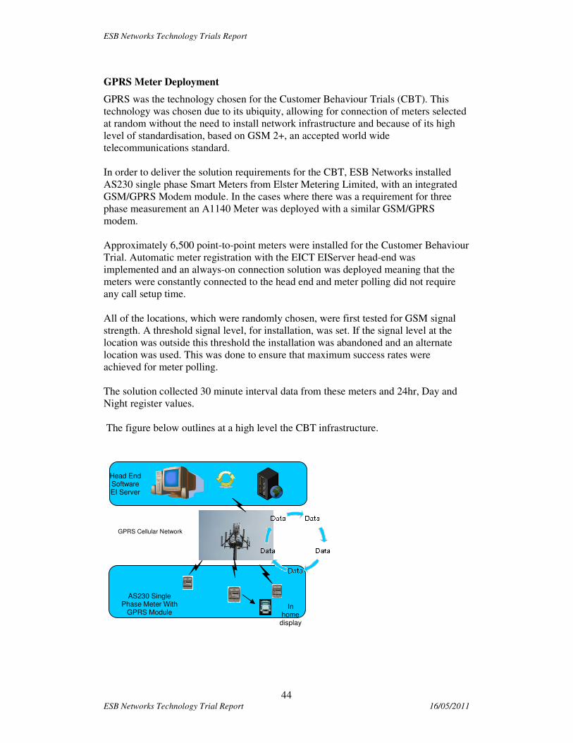
GPRS Meter Deployment
GPRS was the technology chosen for the Customer Behaviour Trials (CBT). This
technology was chosen due to its ubiquity, allowing for connection of meters selected
at random without the need to install network infrastructure and because of its high
level of standardisation, based on GSM 2+, an accepted world wide
telecommunications standard.
In order to deliver the solution requirements for the CBT, ESB Networks installed
AS230 single phase Smart Meters from Elster Metering Limited, with an integrated
GSM/GPRS Modem module. In the cases where there was a requirement for three
phase measurement an A1140 Meter was deployed with a similar GSM/GPRS
modem.
Approximately 6,500 point-to-point meters were installed for the Customer Behaviour
Trial. Automatic meter registration with the EICT EIServer head-end was
implemented and an always-on connection solution was deployed meaning that the
meters were constantly connected to the head end and meter polling did not require
any call setup time.
All of the locations, which were randomly chosen, were first tested for GSM signal
strength. A threshold signal level, for installation, was set. If the signal level at the
location was outside this threshold the installation was abandoned and an alternate
location was used. This was done to ensure that maximum success rates were
achieved for meter polling.
The solution collected 30 minute interval data from these meters and 24hr, Day and
Night register values.
The figure below outlines at a high level the CBT infrastructure.
Head End Software EI Server
AS230 Single Phase Meter With
GPRS Module
GPRS Cellular Network
In home
display

ESB Networks Technology Trials Report
45 ESB Networks Technology Trial Report 16/05/2011
GPRS Meter Registered to head end GPRS Meter showing Signal Strength
5.3.3 Summary of GPRS performance.
GPRS coverage was found to be very good. 5% of locations were excluded from the
trial due to signal levels being below the set threshold. It is believed that this would
rise to 97% were a less exacting threshold level used.
Auto deployment/self registration
Auto deployment/self registration of meters worked in 99% of cases.
Daily collection of profile data
Daily collection of profile data was found to be very good, with a success rate of
97.89% first time reads. The majority of failures were accounted by 4 individual short
duration incidents. When not including the four polling incidents, the average daily
success rate following the scheduled poll was 98.25%, with the highest success rate
being 99.17%.
The average success rate rose to 99.1% by the end of the day. The graph below is the
result of the Daily Scheduled Successful Poll over a twelve month period from
January 2010 to December
2010
% Daily Scheduled Successfull Poll
73.00%
74.00%
75.00%
76.00%
77.00%
78.00%
79.00%
80.00%
81.00%
82.00%
83.00%
84.00%
85.00%
86.00%
87.00%
88.00%
89.00%
90.00%
91.00%
92.00%
93.00%
94.00%
95.00%
96.00%
97.00%
98.00%
99.00%
100.00%
04/01 20/01 05/02 23/02 11/03 30/03 19/04 06/05 24/05 11/06 29/06 15/07 03/08 19/08 06/09 22/09 08/10 27/10 12/11 30/11 16/12
Date
% D
evic
es

ESB Networks Technology Trials Report
46 ESB Networks Technology Trial Report 16/05/2011
Daily collection of register data was as per the collection of interval reads.
Events and alarms
Events and alarms are stored on the meter and collected daily when the meter is
polled. This is a function of the meter design and some alarms and events could be
programmed in the meter to be instantaneous.
On demand tasks
On demand reads were 99% successful at first attempt and took on average 90secs to
complete for a full daily profile.
Remote operation was measured to work on average within 30 seconds of issuing a
command from the head end.
Firmware upgrade
Remote firmware upgrades worked on a meter by meter basis. GPRS is a point to
point technology and broadcast and multicast are not supported. This would be a
significant issue for a full roll out.
5.3.4 Key Learning’s on GPRS
GPRS proved to be a very effective and reliable technology during the course of
the trial.
� GPRS worked well and was very reliable for the 95% of customers that were
covered.
� The meters were easy to deploy, the auto registration process was very
effective.
� It is essential to work closely with the Mobile Network Operators’ to ensure
compatibility of modems and determine optimal configuration
� CBT design will have to be changed for larger for out as always-on
connections unlikely to be allowed
� GPRS is an open standards technology. There are many vendors who will
support a GPRS solution.
� Issues of Mobile Network lock-in need to be resolved if a mobile network
based solution is to be considered as a viable long term solution for a full roll
out.
� There is an issue for mass upgrade or mass on demand activity as the system is
point to point and lacks a broadcast/multicast capability. This will be
restrictive for some future potential smart metering services.
� Visibility into the MNO’s device management platforms is essential
� While GPRS worked for the trial there is an issue over how long this
technology will continue to be supported on all mobile operators network
particularly considering the anticipated lifetime of the smart metering system,
which could last up to 2032.

ESB Networks Technology Trials Report
47 ESB Networks Technology Trial Report 16/05/2011
6 Desktop Studies
Two technologies offered at the time of the procurement process were also of interest
to us. We undertook two desktop studies with vendors to help develop an
understanding of how their technologies work and of their capabilities. Any figures
quoted for these technologies are theoretical in the Irish context, are based on models
and examples provided by the vendors and have not been verified in the field, in Irish
conditions.
6.1 PLC Desktop Study.
The PLC desktop study was carried out with Aclara and was based on their TWACS
technology. A full trial was not possible as a suitably approved meter for Europe was
not available in the timeframe of the trial.
6.1.1 Brief overview of Technology
Aclara's patented Two-Way Automated Communications System (TWACS) employs
a system architecture composed of three layers:
• Computer Communication Equipment (CCE), the Master Station or head-end
system;
• Substation Communication Equipment (SCE), and
• Remote Communication Equipment (RCE), end-point devices or TWACS
transponders.
Figure 1 provides a graphical illustration of a typical TWACS® Technology
implementation
Load Control Transponder
Dis tributionSubstation
Voice Grade Communication
Power
Lines
TWACS Substation Control Equipment
ServiceTo Home
Gas MeterWater MeterLoad Control Transponder
Dis tributionSubstation
Voice Grade Communication
Power
Lines
TWACS Substation Control Equipment
ServiceTo Home
Gas MeterWater Meter
Electric Meter, Hard Disconnect
TWACS Network
Administrator
Client Workstation (PC)
MainframeMainframe
Electric Meter, Hard Disconnect
TWACS Network
Administrator
Client Workstation (PC)
MainframeMainframe
Communication FrontEnd Processors (FEPs)
TNS Client Workstations (PCs)
TWACSMaster Station
Oracle
UTILITY ENTERPRISE NETWORK (WAN/LAN)
Billing/CIS
Mainframe
Commercial Meter Transponder
Communication FrontEnd Processors (FEPs)
TNS Client Workstations (PCs)
TWACSMaster Station
Oracle
UTILITY ENTERPRISE NETWORK (WAN/LAN)
Billing/CIS
Mainframe
Commercial Meter Transponder
SCADA, EMS, OMS, etc
Outbound signalling is communication from the substation to the end-point devices
and inbound signalling for end-point device communication detected at the substation.
This is a low bandwidth technology that reliance on clever use of concurrency
techniques to deliver its service. This is a proprietary technology.
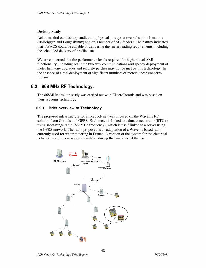
ESB Networks Technology Trials Report
48 ESB Networks Technology Trial Report 16/05/2011
Desktop Study
Aclara carried out desktop studies and physical surveys at two substation locations
(Balbriggan and Loughshinny) and on a number of MV feeders. Their study indicated
that TWACS could be capable of delivering the meter reading requirements, including
the scheduled delivery of profile data.
We are concerned that the performance levels required for higher level AMI
functionality, including real time two way communications and speedy deployment of
meter firmware upgrades and security patches may not be met by this technology. In
the absence of a real deployment of significant numbers of meters, these concerns
remain.
6.2 868 MHz RF Technology.
The 868MHz desktop study was carried out with Elster/Coronis and was based on
their Wavenis technology
6.2.1 Brief overview of Technology
The proposed infrastructure for a fixed RF network is based on the Wavenis RF
solution from Coronis and GPRS. Each meter is linked to a data concentrator (RTU+)
using short-range radio (868MHz frequency), which is itself linked to a server using
the GPRS network. The radio proposed is an adaptation of a Wavenis based radio
currently used for water metering in France. A version of the system for the electrical
network environment was not available during the timescale of the trial.

ESB Networks Technology Trials Report
49 ESB Networks Technology Trial Report 16/05/2011
The key components of the solution are:
• Meter: Elster AS230
• Comms Module - RF: AM600
• Repeaters – Mains Powered
• Data Concentrator: (RTU+)
• Head-end Server: EIserver
The network topology proposed is not a mesh but a radial trunk and branch network,
per cell. The meter radio module power is limited to 25mW by regulation and
therefore has limited range.
Transmission speed is set to 19.2Kbps, the usual data communication rate selection
for metering applications.
As the meters are polled by the DC only one meter can transmit at a time, per cell, this
should minimise intra- and inter-cell interference.
6.2.2 Key Learning’s on 868 RF Technology solution.
• The technology has not yet been adapted for the Electricity market and no
large scale deployment exists.
• The technology utilises the unlicensed 868MHz band, which is limited to
2MHz of bandwidth, divided into smaller sub-bands.
• The technology does not yet have meshing, repeating or self healing
capability.
• Wavenis is a published protocol and a Wavenis forum has been established
which is open to meter and communications system vendors and to utilities.
This reduces the risks associated with lock-in due to proprietary technologies.
• Concerns exist over the range of the 25mW radio module. This is based on
studies carried out by ESB Networks using similar radios. therefore large
numbers of repeaters will be required, both in Urban and Rural environments
• Network planning and design is based on averages, estimates and experience.
• We are concerned that the performance levels required for higher level AMI
functionality, including real time two way communications and speedy
deployment of meter firmware upgrades and security patches may not be met
by this technology. In the absence of a real deployment of significant numbers
of meters, these concerns remain.

ESB Networks Technology Trials Report
50 ESB Networks Technology Trial Report 16/05/2011
7 Meter
The main focus during each of the trials was to collect scheduled interval data,
registers and events reads on a daily basis from the installed smart meters. Most of the
other smart functionalities within the meters themselves were actually trialled in a
controlled test environment, to minimise disruption to customers.
• In all cases the remote operation of the switch in the meter worked well.
• The Trilliant comms module on the Iskraemeko meter was able to provide a
last gasp message in the event of a loss of network supply. This demonstrated
one of the benefits of wireless mesh.
• The Elster 1-phase meter also had very significant and useful power quality
information.
Smart meters by their nature are complex devices with considerable processing power
on board. However, there were some hardware and software issues with some of the
meters. These included spurious alarms and events and some electronic component
issues. None of these impacted on the metrological component which was rigorously
tested.
Tests carried out to determine the viability of carrying out remote firmware upgrades
(non-metrology) for meters, modems and data concentrators were eventually
successful. This proved much easier to implement on LAN based rather that point to
point technology. This functionality will be an essential feature of any full rollout.
Even with a clear focus on the use of open standards and well tested systems, it is
widely recognised that the combination of the different Energy Market requirements
within each of the EU jurisdictions, and the complexities in any Smart Metering
implementation, will, of necessity, require a significant level of customisation for any
smart metering rollout
From the perspective of all components of the meter there is a clear need for
sufficient soak time during a smart metering system tendering and evaluation process,
whereby meters could be fully configured and their full remote manageability verified
within a proper end-to-end implementation. Major security testing should also take
place at this time.
A number of the meters available for the trials were based fully or partly around
DLMS / COSEM data objects, and as this is the way EU standardisation may direct
us, it was a good learning exercise. However, the range of OBIS codes will need to
be expanded slightly to minimise the number of Vendor-defined codes in use.
During 2009, a Smart Metering Coordination Group (SMCG) was set up by three of
the main standards organisations in Europe, CEN, CENELEC and ETSI, in response
to EU mandate M/441. One of the outputs of this exercise is a proposal to specify
range of possible smart Additional Functionalities that should be considered by EU
countries as they work towards the mandatory rollout of Smart Metering by 2020.
ESB Networks’ initial metering system specification has proved to be very closely
aligned with the functionalities subsequently defined by the SMCG, so the experience
gained during the pilot will be very beneficial in progressing towards a possible full
rollout.
ESB Networks Technology Trials Report
51 ESB Networks Technology Trial Report 16/05/2011
8 Testing
The testing approach adopted involved comprehensive, integrated test of the meter,
telecommunications, newly configured ESB IT systems and all associated legacy
systems. The programme test process included vendor testing, IT system testing,
meter installation testing and data integrity testing. There were a number of stages of
testing, from unit testing & vendor unit testing, through system integration test and
user acceptance test. A final deployment acceptance test took place as a deployment
ramp up.
ESB Networks Technology Trials Report
52 ESB Networks Technology Trial Report 16/05/2011
9 Security and data protection
9.1 Procedures for trial
Customer privacy and the security of the metering data collected were key
considerations during the design, testing and operational phases of the Smart Metering
Trials. The security mechanisms available in the solutions selected for the trials were
fully implemented according to each vendors best practice guidelines. Prior to
deploying any of the technologies offered for the trials, a risk analysis was carried out
to access the security services available within each solution. This analysis focussed
on whether metering data could be exposed to unauthorised individuals. It also
considered if such an exposure would allow the data to be modified or would allow
the customer to be identified. The risk analysis concluded that the technologies were
acceptable for deployment in a trial context.
The security services available for each trial were then fully tested prior to
implementation and any implementation issues identified were fully rectified. A
Penetration Test was also carried out by an external Security Company on the Meters,
In-Home Displays, GPRS Network solution and head end solution deployed for the
CBT trial. The recommendations from this Penetration Test were implemented where
possible (some recommendations could not be implemented as they would have
required hardware changes in devices).
The detailed consumption data collected during the trials was stored in secure head
end systems. Access to these systems and the access rights of individuals on these
systems were tightly controlled and audited. The data in these systems was handled in
strict compliance with the requirements of the Data Protection Act.
The detailed consumption data from the CBT trial was securely delivered to Suppliers
and CER Statisticians via encrypted files. Controls were put in place to ensure that
each Supplier only received the data for their own customers. The data provided to
CER Statisticians was anonymized so that the individual customers could not be
identified. Data Transfer Agreements were signed between ESB Networks and the
Statisticians in accordance with Data Protection Act requirements. These agreements
described the purpose for which the data was provided and how it should be securely
handled.
9.2 Full roll out issues
From a security perspective the following lessons were learned from the both direct
experience in the trials and from information from other smart metering stakeholders.
These are general opinions and should not be considered as applying fully to any one
system deployed in the trial:
• The mechanisms for securing the smart metering infrastructure vary
considerably from vendor to vendor. Where metering vendors have considered
security, they have tended to focus mainly on encryption of data while in
transit. However, they also need to put the same emphasis on how devices

ESB Networks Technology Trials Report
53 ESB Networks Technology Trial Report 16/05/2011
securely join the network, how data is securely stored on devices and how
firmware and configuration updates are securely downloaded to devices.
• The supply chain leading up to the manufacture and delivery of devices to
utility customers and their software development lifecycles need to include
processes and protections to ensure that the hardware and software cannot be
compromised prior to delivery to the utility.
• Many vendors use proprietary security mechanisms at present. This is
generally a consequence of the proprietary networking protocols being used.
Ideally, the Internet Protocol should be used at the networking layer for all
smart metering solutions and the well understood and standardised security
mechanisms adopted by other security sensitive industries (such as banking)
should be deployed. This appears to be happening as more of the traditional
networking vendors begin to deliver smart metering products.
• The computing power and memory constraints of smart meters limit the types
of security solutions which can be deployed. This is also a significant
consideration for battery powered devices used in the home. As the level of
integration between the smart meter and other devices used in the home
increases, the level of security required at the interface between the smart
meter and in-home devices increases accordingly.
• If pubic networks are used to deliver all or portions of the smart metering
communications infrastructure, this highlights the need for application level
security as the utility does not have control of the processing of network traffic
while it traverses these public networks. Device authentication and end-to-end
application layer encryption become very necessary in these scenarios. The
DLMS/COSEM metering standard provides for suitable authentication and
encryption services.
• Role based access to devices and systems is available to a limited extent in
current smart metering solutions. However, much more granular definition of
roles and associated access rights is required.
• The impact of natural disasters, terrorism, and human error must also be
considered when deploying solutions, particularly if these infrastructures are
to be expanded to deliver Smart Grid functionality and must be highly
available. A holistic approach to the design of the solution which takes into
account the People and Process dimensions in addition to the Technology
dimension is required.
• Logging and auditing of all activity on the infrastructure is also important. The
next generation of smart metering solutions must support automatic facilities
for analysing activity within the entire system to detect non-typical activities
(similar to Intrusion Detection Systems and Zero-Day Virus/Worm Protection
solutions deployed for Internet services today).
• As with all aspects of business, the cost of providing a secure infrastructure
must be balanced against the value to someone else of exposing the risk being
protected against. It has to be recognised that no infrastructure can ever be
100% secure indefinitely. Circumstances change and security processes must
be constantly reviewed and improved.
ESB Networks Technology Trials Report
54 ESB Networks Technology Trial Report 16/05/2011
10 Deployment and installation
During the Trials ESB Networks gathered a significant amount of information at the
wiring interface between the meter and the customer’s premises. ESB Networks
network technicians were requested to complete a short questionnaire at each
customer’s premises in the GPRS based trial as these were randomly selected
representative customers. Where at all possible, we strived to replace the meter and
leave a safety letter in situations where there were issues with aspects of a customer’s
electrical installation. However, there were also circumstances where the NT did not
carry out any work due to problems encountered or the state of the customer’s
electrical installation. In these situations the call was cancelled and an explanatory
letter was left with the customer.
There are a number of key areas at the technical customer interface identified which
will have to be rectified as part of a full roll out program. These will impact on the
cost of a full roll out;
• 1.5% of all installations had missing or damaged meter box doors
• 0.4% of all installations were found to have poor or inaccessible meter
locations or space problems for the meters.
• 0.2 % of external meter boxes had moisture ingress problems
• 0.4% of installations had old legacy metering arrangements with multiple
metering
• 0.6% of all installations had issues wiring immediate beyond the meter. . In the
case of these installations there may be substantial cost on the customer side.
• Approximately 10% of the installations required their main fuses to be
replaced. The assumption is that these will be replaced as part of the cut-out
replacement program.

ESB Networks Technology Trials Report
55 ESB Networks Technology Trial Report 16/05/2011
11 Related Projects
ESB Networks are also involved in a number of other areas of work as part of the
current smart metering trials. These areas include a dual fuel trial with BGN where we
are looking at the concept of the smart electricity meter being used to provide a
communications link to and from a smart gas meter. We are also undertaking a trial
with ESB Electric Ireland on examining how smart meters could support prepay
services for the customer.

ESB Networks Technology Trials Report
56 ESB Networks Technology Trial Report 16/05/2011
12 Possible Future Work
Ongoing developments in standardisation, technology and telecommunications
regulation are continually enhancing and adding to the options available and their
capability. The more recent entry of major communications systems vendors into the
market is accelerating the availability of IP based solutions as credible options which
require detailed investigation
Technologies to be kept under review include (but are not limited to) OFDM based
PLC, and emerging RF solutions in the sub 1GHz band.
The trials utilised GPRS as the designated WAN technology. This was done to
facilitate flexibility, speed and ease of deployment and due to the lack of a readily
available and ubiquitous alternative. Before engaging in a full roll out suitable
available WAN technologies should be assessed.
ESB Networks Technology Trials Report
57 ESB Networks Technology Trial Report 16/05/2011
13 Conclusions
Smart metering is a complex program. The experience in the trial and that of other
utilities who have undertaken smart metering deployment reinforces this view.
Smart metering is the start of something bigger, it isn’t just an IT project, and it
introduces change across the organization and industry. In addition the program can
be up to 7 years duration with almost half the time required before full deployment
begins. Often the biggest risks are with devices in the field and therefore you need an
extensive test program. The overall program would have a number of key phases
these phases include:
• Definition of requirements, design, planning and specification and
procurement. At the end of this phase we will have selected the solutions for
the full roll out.
• Detailed design test and installation of all new IT systems including
integration testing to meters.
• Roll out of communications infrastructure and installation of meters and any
other devices.
The smart metering technologies trialled need improvement to enable a feasible smart
metering rollout. This reflects the fact that smart metering is still an immature
technology where significant components of many available solutions are proprietary.
However upcoming developments in standardisation, technology and
telecommunications regulation should enhance the options available and their
capability. Based on assumptions on the timetable we could be deciding in late 2012
on the full roll out solution.
The following overall high level conclusions can be drawn from the technology trials.
� Trialled LAN technologies are not sufficiently developed for immediate full
roll out based on anticipated high level functional and demanding performance
requirements
� The proprietary nature of some offerings also presents significant commercial
and technology risk. This risk will be mitigated by the specification of
internationally accepted standards for all technology choices.
� Ideally, the Internet Protocol should be used at the networking layer for all
smart metering solutions and the well understood and standardised security
mechanisms adopted by other security sensitive industries (such as banking)
should be deployed.
� Working with vendors all solutions can be improved.
� Taking into account the timetable above and the issues identified in the trial
next generation PLC would appear to offer best prospects for an urban
solution. This is focus of activity in Europe.
� Existing national and European regulations on spectrum availability means
that currently available wireless technologies all have issues leaving GPRS/3G
as the leading option for almost 700k rural customers
� Mesh systems, deployed outside of Europe, operating in the sub-1Ghz range
and at relatively higher transmit power appear to address many of these issues.

ESB Networks Technology Trials Report
58 ESB Networks Technology Trial Report 16/05/2011
We believe that more suitable wireless spectrum should be made available in
the sub 1GHz area.
� If required to roll out some smart meters on an ad-hoc basis in the near term
then we should develop an interim solution based on GPRS with a
DLMS/COSEM meter.