ELECTRICAL THEORY AND DIAGNOSIS OF MAJOR … · ELECTRICAL THEORY AND DIAGNOSIS OF ... Microwave...
76
CONSUMER SERVICES TECHNICAL EDUCATION GROUP PRESENTS G-20 JOB AID Part No. 4322536A ELECTRICAL THEORY AND DIAGNOSIS OF MAJOR APPLIANCES
Transcript of ELECTRICAL THEORY AND DIAGNOSIS OF MAJOR … · ELECTRICAL THEORY AND DIAGNOSIS OF ... Microwave...
CONSUMER SERVICES TECHNICALEDUCATION GROUP PRESENTS G-20
JOB AIDPart No. 4322536A
ELECTRICAL THEORYAND DIAGNOSIS OF
MAJOR APPLIANCES
TABLE OF CONTENTS
SECTION 1
Basic Electricity ....................................................................................................................... 1-1
Introduction ........................................................................................................................ 1-1
Electrical Terms ................................................................................................................. 1-2
Ohm’s Law ......................................................................................................................... 1-4
Circuit Conditions............................................................................................................. 1-10
Types Of Circuits ............................................................................................................. 1-12
Opens And Shorts ........................................................................................................... 1-17
SECTION 2
Wiring Diagrams...................................................................................................................... 2-1
Introduction ........................................................................................................................ 2-1
Wiring Diagram Terms ....................................................................................................... 2-2
Wiring Diagram Colors ....................................................................................................... 2-3
Wiring Diagram Symbols ................................................................................................... 2-4
Tracing Circuits ................................................................................................................ 2-12
Using Strip Circuits .......................................................................................................... 2-25
Closing Switches ............................................................................................................. 2-29
Electric Range Wiring Diagram........................................................................................ 2-36
Gas Range Wiring Diagram ............................................................................................. 2-37
Electric Built-In Range Wiring Diagram ........................................................................... 2-38
Electric Built-In Range Relay Logic Chart ........................................................................ 2-39
Microwave Oven Wiring Diagram .................................................................................... 2-40
Self-Cleaning Gas Range Wiring Diagram ...................................................................... 2-41
Duet Dryer Wiring Diagram.............................................................................................. 2-42
Duet Washer Wiring Diagram .......................................................................................... 2-43
Calypso Washer Wiring Diagram..................................................................................... 2-44
Dishwasher Wiring Diagram ............................................................................................ 2-45
Page
Copyright © 2003, Whirlpool Corporation, Benton Harbor, MI 49022
Basic Electricity Section 11-1
SECTION 1
BASIC ELECTRICITY
INTRODUCTION
Knowing the various types of electrical systems used in modern house-
hold appliances will assist you with evaluating the appliance complaints
caused by electrical system failures. This is an important key to the
fundamental diagnostic process. As you work through this section, you
will find that each topic is set up to provide you with:
• A definition of the system or component.
• An explanation of its operation.
• An example of how its function may be applied to an appliance
overall operation.
The beginning of this section explains some of the basic electrical
fundamentals. Exercises will be used to help in the learning process.
To prepare you for the basis of the content and exercises in this sec-
tion, we will review some of these electrical fundamentals.
Basic Electricity Section 11-2
ELECTRICAL TERMS
The following is a list of electrical terms and definitions used throughout
this section:
Voltage: Usually referred to as “Electromotive Force”
(EMF). This force causes electrons to move
from negative to positive.
Current (Amperage): A unit of measurement referring to the inten-
sity, or amount of electrical force through a
circuit.
Direct Current (DC): Current that flows only in one direction. DC
current is used in the following applications:
a) Mostly in low-voltage conditions.
b) Circuits that are conducted over rela-
tively short distances.
c) Appliances with electronic controls.
Alternating Current (AC): Current that flows in both directions. AC
current is used in the following applications:
a) Low- and high-voltage conditions.
b) Circuits that are conducted over long
distances.
c) Used to operate the main components in
an appliance.
Resistance: The restriction to the flow of electricity in a
circuit. Resistance is measured in ohms (Ω).
Infinite Resistance is so much resistance
that current cannot flow through the circuit
(“open” circuit).
Zero Resistance is no resistance and
current can flow through the circuit (“closed”
circuit).
Basic Electricity Section 11-3
Wattage: The unit of measurement for power, or the
work being done by electricity.
Load: Component that converts electricity to heat,
light, or motion. All loads restrict the flow of
electricity while performing their work.
Conductor: Material through which electricity can flow.
It will usually be a copper wire, and some-
times the chassis, or metal frame, on which
the components are mounted.
Short: A circuit that offers no resistance to the
current flowing through it. A direct short will
cause a fuse to blow, or possibly start an
electrical fire.
Shorted Switch: A switch that offers no resistance to the flow
of current through it. The switch may have a
shorted contact.
Open Switch: A switch that will not allow current to flow
through it. The switch may have an open
contact.
Shunt: A bypass around a load that still offers
resistance in the circuit for the flow of cur-
rent.
Circuit: A complete path through which electricity
can travel.
Basic Electricity Section 11-4
OHM’S LAW
There is a fundamental relationship between voltage, amperage, and
resistance in a closed functional circuit. This relationship is known as
“Ohm’s Law.” Ohm’s law states that:
a) Current is directly proportional to the applied voltage.
b) Current is inversely proportional to the circuit resistance.
What this really means is:
a) When the circuit voltage increases, the current increases.
b) When the circuit voltage decreases, the current decreases.
c) When the circuit resistance increases, the current decreases.
d) When the circuit resistance decreases, the current increases.
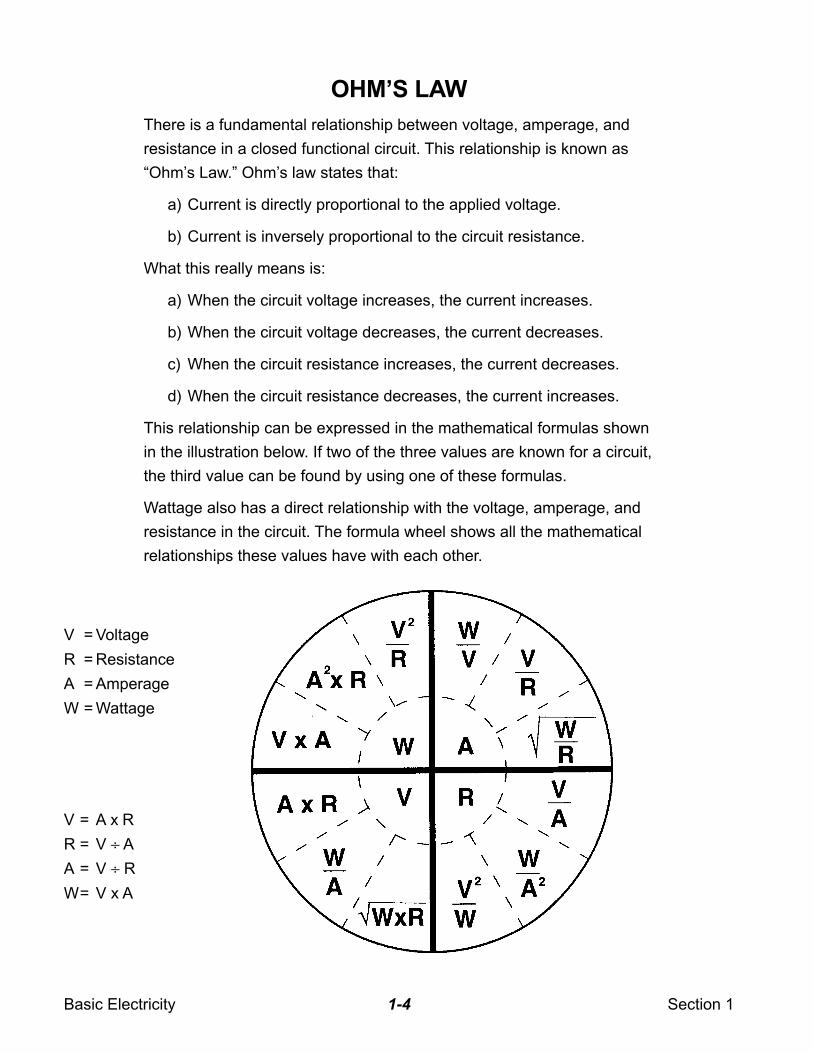
This relationship can be expressed in the mathematical formulas shown
in the illustration below. If two of the three values are known for a circuit,
the third value can be found by using one of these formulas.
Wattage also has a direct relationship with the voltage, amperage, and
resistance in the circuit. The formula wheel shows all the mathematical
relationships these values have with each other.
V = A x R
R = V ÷ A
A = V ÷ R
W= V x A
V = Voltage
R = Resistance
A = Amperage
W = Wattage
Basic Electricity Section 11-5
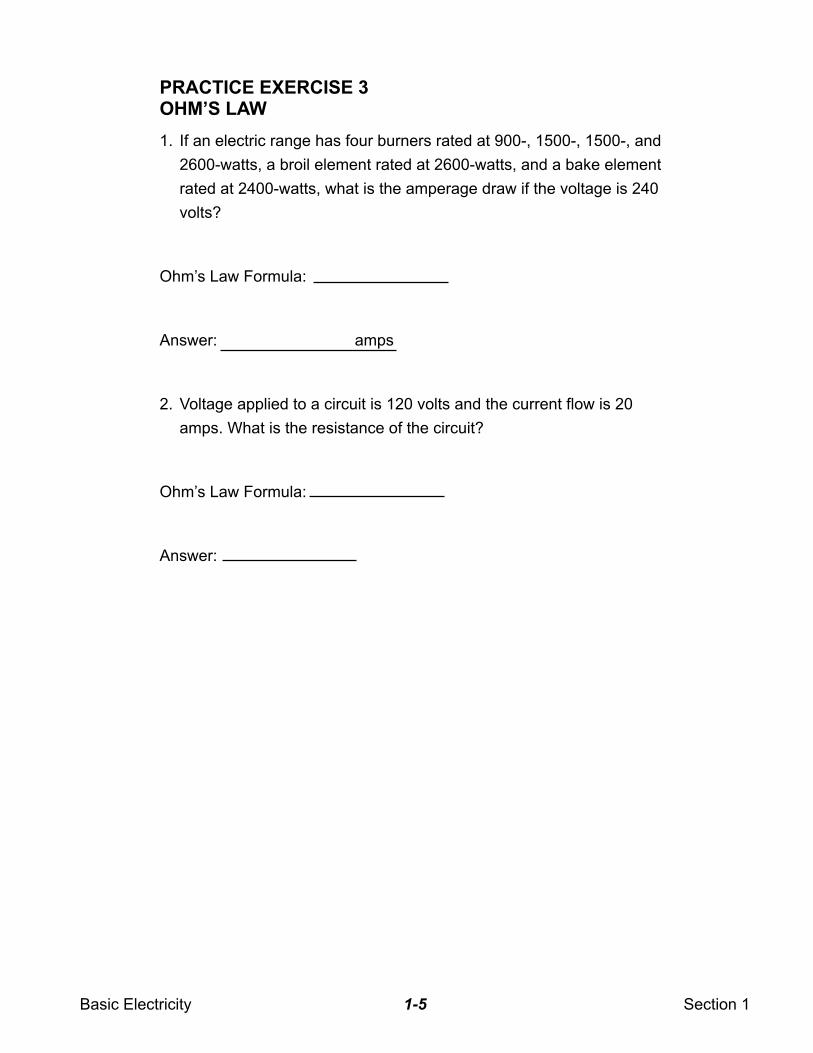
PRACTICE EXERCISE 3OHM’S LAW
1. If an electric range has four burners rated at 900-, 1500-, 1500-, and
2600-watts, a broil element rated at 2600-watts, and a bake element
rated at 2400-watts, what is the amperage draw if the voltage is 240
volts?
Ohm’s Law Formula:
Answer: amps
2. Voltage applied to a circuit is 120 volts and the current flow is 20
amps. What is the resistance of the circuit?
Ohm’s Law Formula:
Answer:
Basic Electricity Section 11-6
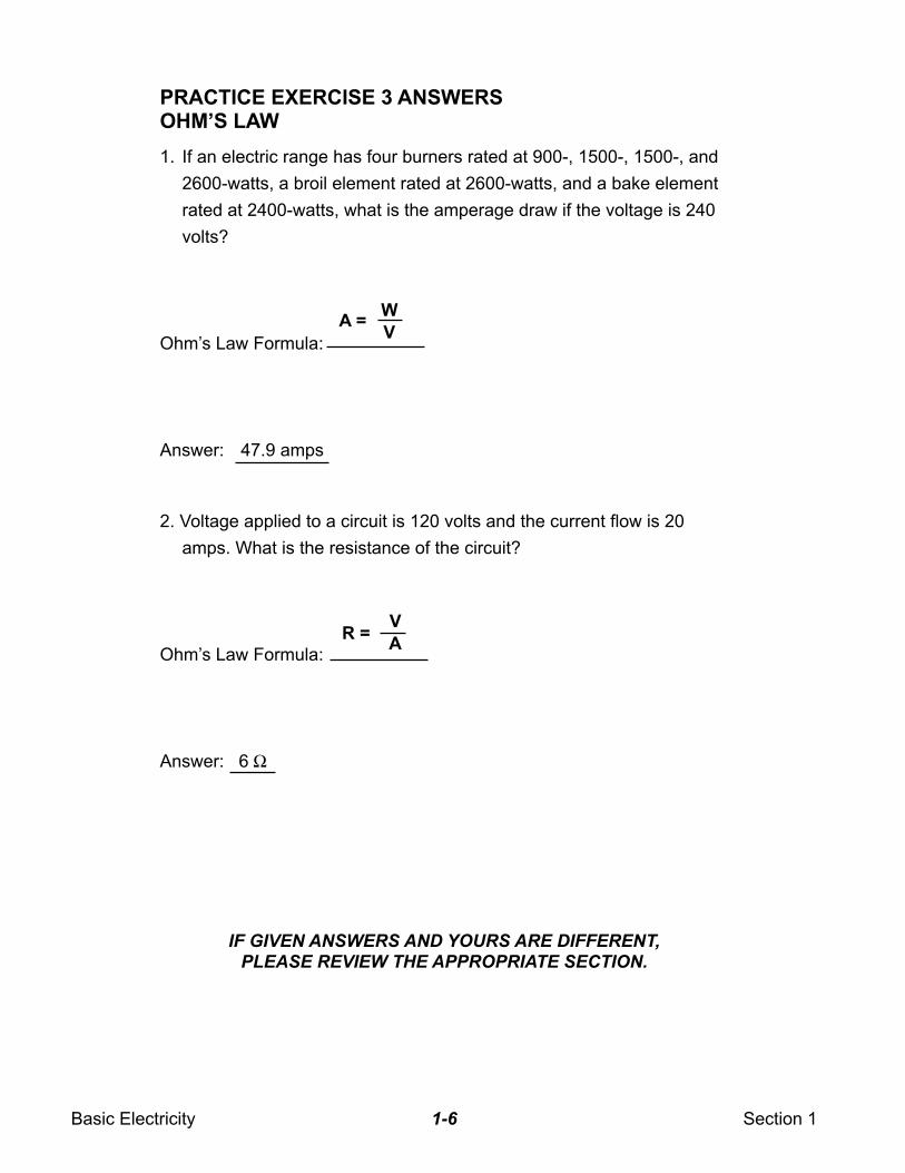
PRACTICE EXERCISE 3 ANSWERSOHM’S LAW
1. If an electric range has four burners rated at 900-, 1500-, 1500-, and
2600-watts, a broil element rated at 2600-watts, and a bake element
rated at 2400-watts, what is the amperage draw if the voltage is 240
volts?
Ohm’s Law Formula:
Answer: 47.9 amps
2. Voltage applied to a circuit is 120 volts and the current flow is 20
amps. What is the resistance of the circuit?
Ohm’s Law Formula:
Answer: 6 Ω
A =W
V
R =V
A
IF GIVEN ANSWERS AND YOURS ARE DIFFERENT,PLEASE REVIEW THE APPROPRIATE SECTION.
Basic Electricity Section 11-7
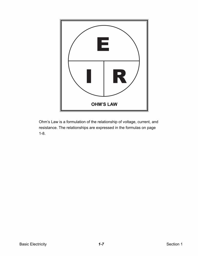
E
I R
OHM’S LAW
Ohm’s Law is a formulation of the relationship of voltage, current, and
resistance. The relationships are expressed in the formulas on page
1-8.
Basic Electricity Section 11-8
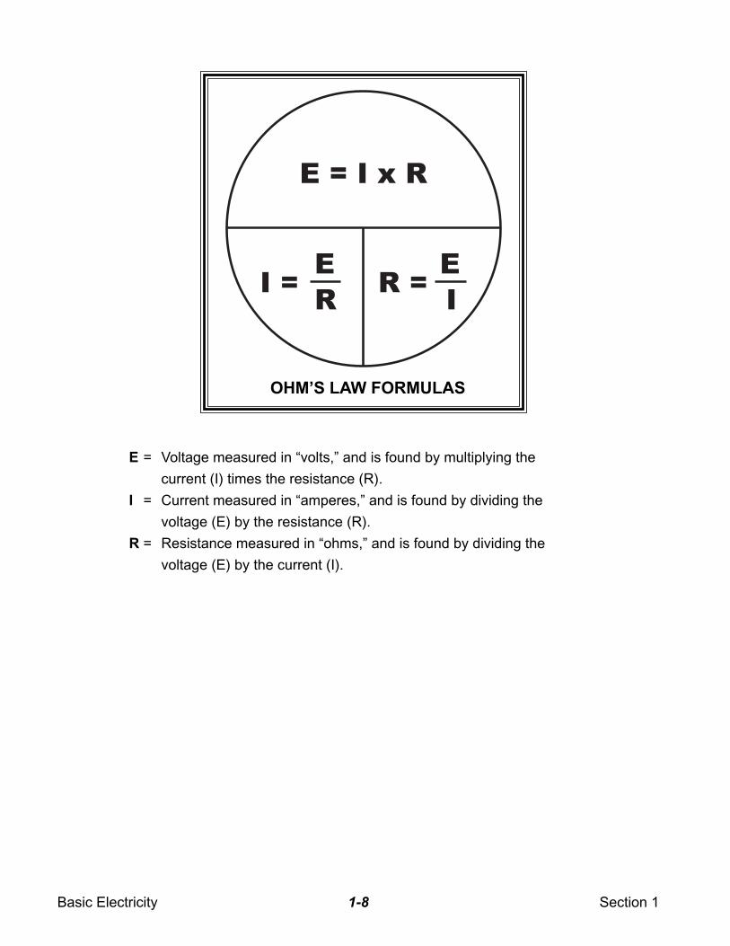
E = I x R
E
RI =
E
IR =
OHM’S LAW FORMULAS
E = Voltage measured in “volts,” and is found by multiplying the
current (I) times the resistance (R).
I = Current measured in “amperes,” and is found by dividing the
voltage (E) by the resistance (R).
R = Resistance measured in “ohms,” and is found by dividing the
voltage (E) by the current (I).
Basic Electricity Section 11-9
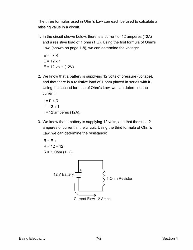
The three formulas used in Ohm’s Law can each be used to calculate a
missing value in a circuit.
1. In the circuit shown below, there is a current of 12 amperes (12A)
and a resistive load of 1 ohm (1 Ω). Using the first formula of Ohm’s
Law, (shown on page 1-8), we can determine the voltage:
E = I x R
E = 12 x 1
E = 12 volts (12V).
2. We know that a battery is supplying 12 volts of pressure (voltage),
and that there is a resistive load of 1 ohm placed in series with it.
Using the second formula of Ohm’s Law, we can determine the
current:
I = E ÷ R
I = 12 ÷ 1
I = 12 amperes (12A).
3. We know that a battery is supplying 12 volts, and that there is 12
amperes of current in the circuit. Using the third formula of Ohm’s
Law, we can determine the resistance:
R = E ÷ I
R = 12 ÷ 12
R = 1 Ohm (1 Ω).
12 V Battery+
– 1 Ohm Resistor
Current Flow 12 Amps
Basic Electricity Section 11-10
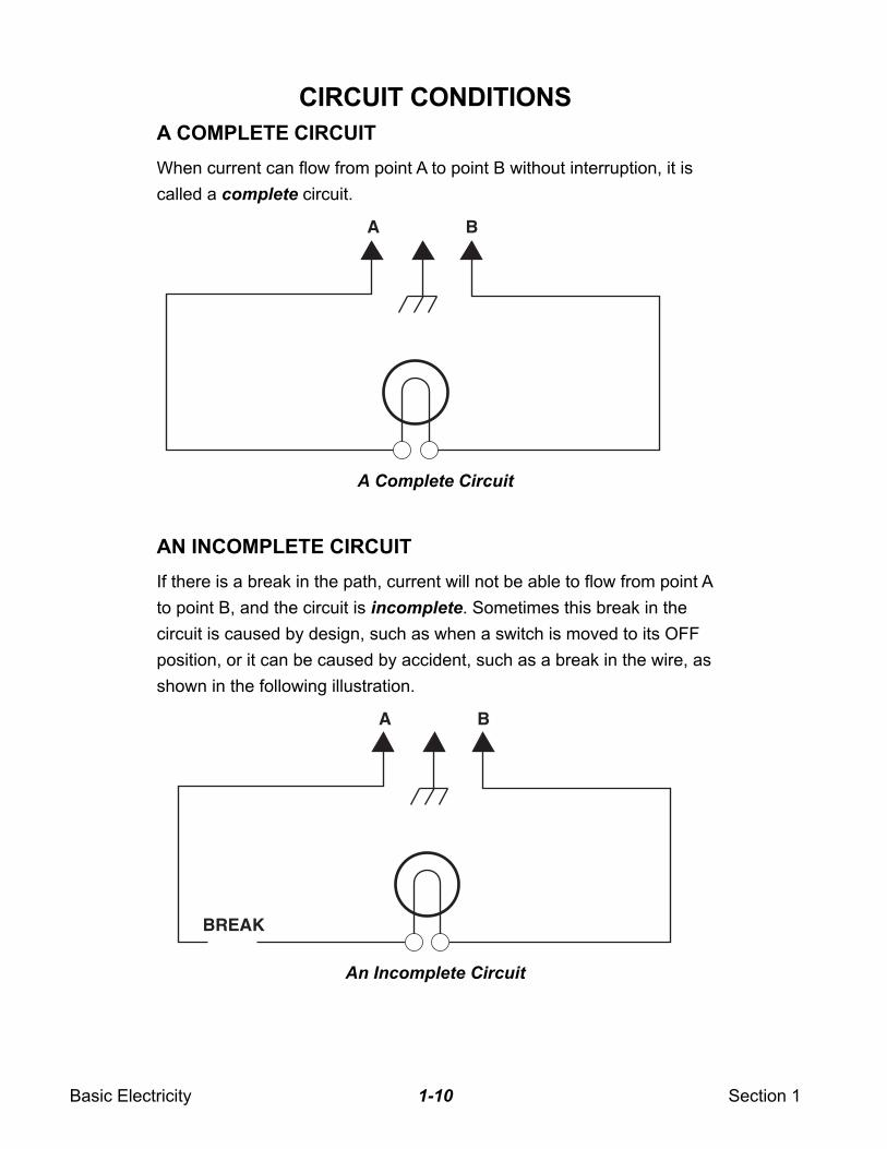
CIRCUIT CONDITIONS
A COMPLETE CIRCUIT
When current can flow from point A to point B without interruption, it is
called a complete circuit.
AN INCOMPLETE CIRCUIT
If there is a break in the path, current will not be able to flow from point A
to point B, and the circuit is incomplete. Sometimes this break in the
circuit is caused by design, such as when a switch is moved to its OFF
position, or it can be caused by accident, such as a break in the wire, as
shown in the following illustration.
A Complete Circuit
An Incomplete Circuit
A B
A B
BREAK
Basic Electricity Section 11-11
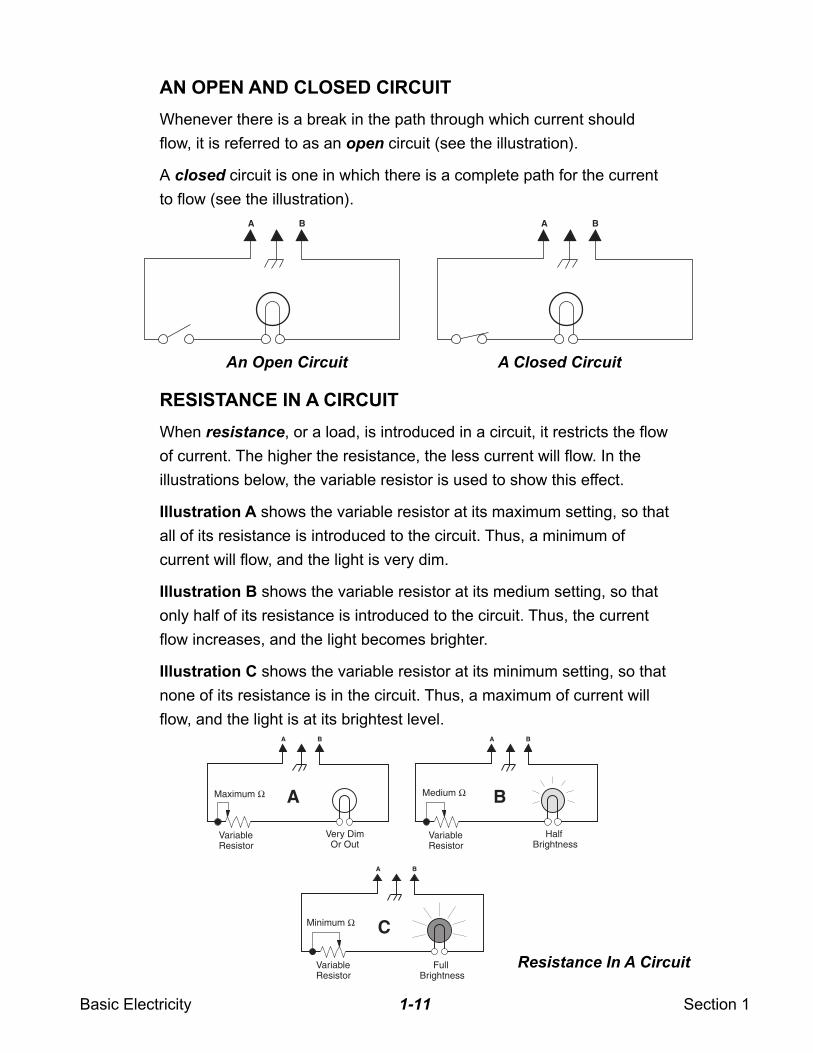
AN OPEN AND CLOSED CIRCUIT
Whenever there is a break in the path through which current should
flow, it is referred to as an open circuit (see the illustration).
A closed circuit is one in which there is a complete path for the current
to flow (see the illustration).
RESISTANCE IN A CIRCUIT
When resistance, or a load, is introduced in a circuit, it restricts the flow
of current. The higher the resistance, the less current will flow. In the
illustrations below, the variable resistor is used to show this effect.
Illustration A shows the variable resistor at its maximum setting, so that
all of its resistance is introduced to the circuit. Thus, a minimum of
current will flow, and the light is very dim.
Illustration B shows the variable resistor at its medium setting, so that
only half of its resistance is introduced to the circuit. Thus, the current
flow increases, and the light becomes brighter.
Illustration C shows the variable resistor at its minimum setting, so that
none of its resistance is in the circuit. Thus, a maximum of current will
flow, and the light is at its brightest level.
An Open Circuit A Closed Circuit
A B A B
A
A B
C
B A B
A B
Maximum Ω Medium Ω
Minimum Ω
VariableResistor
VariableResistor
VariableResistor
Very DimOr Out
Half Brightness
Full Brightness
Resistance In A Circuit
Basic Electricity Section 11-12
TYPES OF CIRCUITS
When evaluating the operation of an electrical circuit, it is important to
understand how electricity will behave in the circuit. There are three
types of circuits you will encounter when diagnosing electrical systems.
These types of circuits are:
1. Series circuits
2. Parallel circuits
3. Series-parallel circuits (which are combinations of the first two kinds)
These three types of circuits will be discussed next.
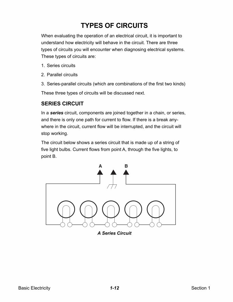
SERIES CIRCUIT
In a series circuit, components are joined together in a chain, or series,
and there is only one path for current to flow. If there is a break any-
where in the circuit, current flow will be interrupted, and the circuit will
stop working.
The circuit below shows a series circuit that is made up of a string of
five light bulbs. Current flows from point A, through the five lights, to
point B.
A Series Circuit
A B
Basic Electricity Section 11-13
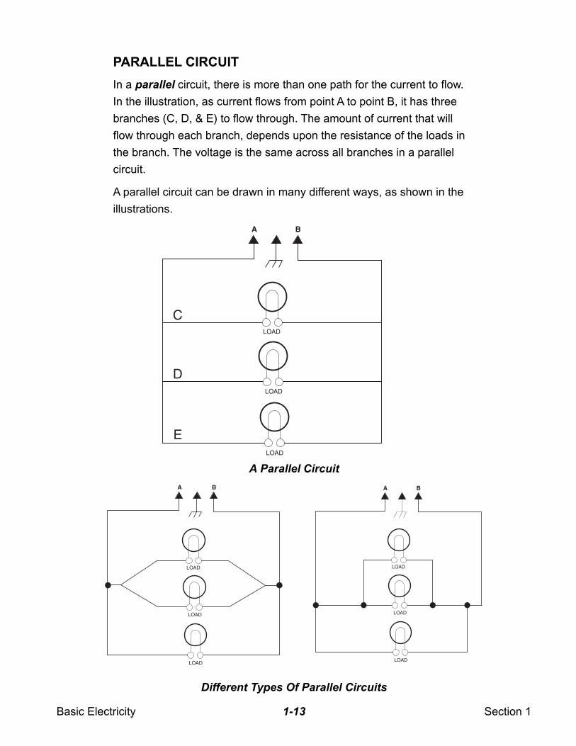
PARALLEL CIRCUIT
In a parallel circuit, there is more than one path for the current to flow.
In the illustration, as current flows from point A to point B, it has three
branches (C, D, & E) to flow through. The amount of current that will
flow through each branch, depends upon the resistance of the loads in
the branch. The voltage is the same across all branches in a parallel
circuit.
A parallel circuit can be drawn in many different ways, as shown in the
illustrations.
A Parallel Circuit
A
C
D
E
B
LOAD
LOAD
LOAD
Different Types Of Parallel Circuits
A B
LOAD
LOAD
LOAD
A B
LOAD
LOAD
LOAD
Basic Electricity Section 11-14
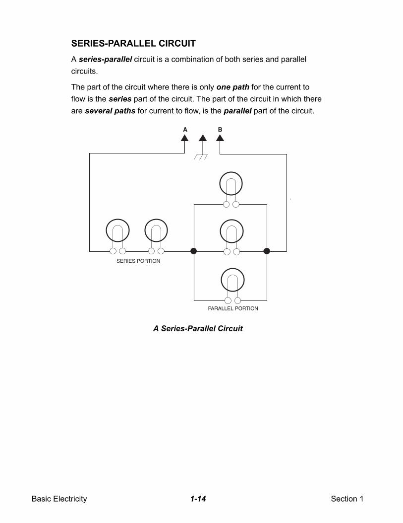
SERIES-PARALLEL CIRCUIT
A series-parallel circuit is a combination of both series and parallel
circuits.
The part of the circuit where there is only one path for the current to
flow is the series part of the circuit. The part of the circuit in which there
are several paths for current to flow, is the parallel part of the circuit.
A B
PARALLEL PORTION
SERIES PORTION
A Series-Parallel Circuit
Basic Electricity Section 11-15
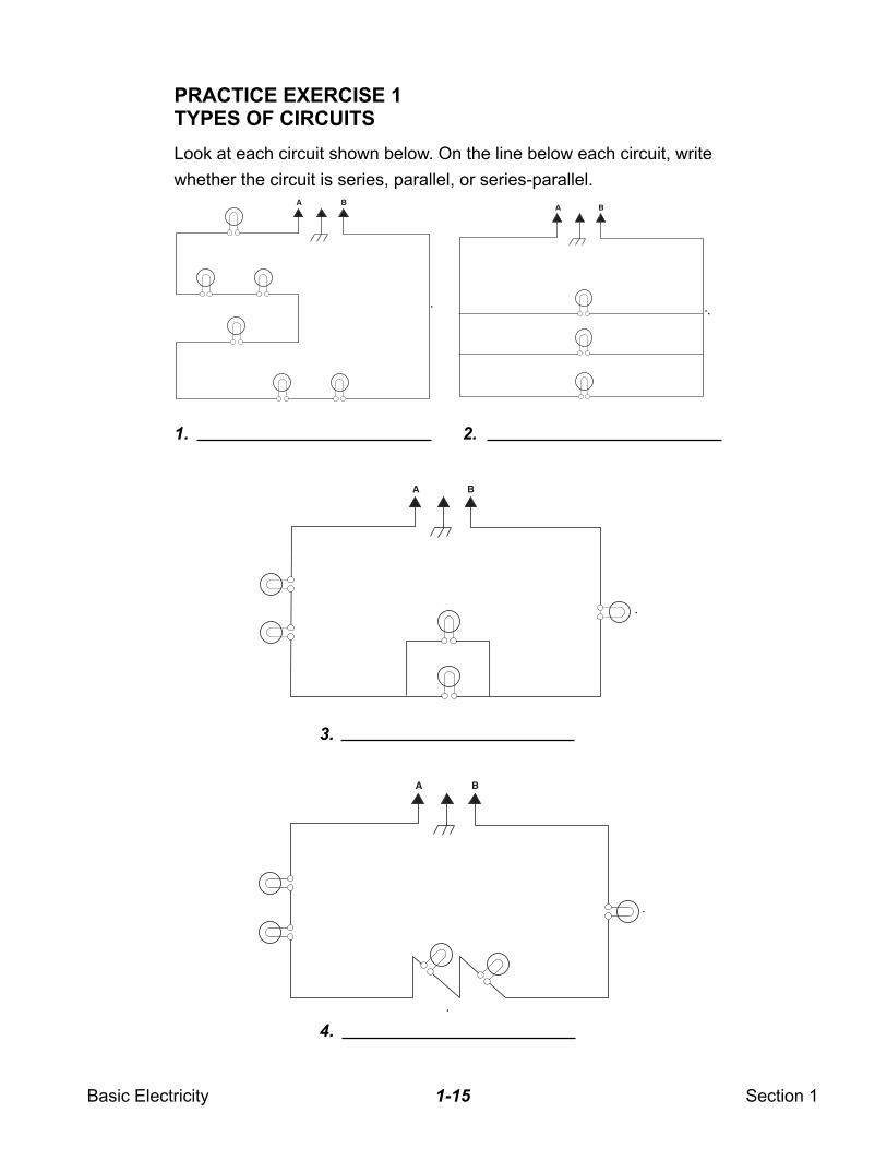
PRACTICE EXERCISE 1TYPES OF CIRCUITS
Look at each circuit shown below. On the line below each circuit, write
whether the circuit is series, parallel, or series-parallel.A B
A B
A B
A B
1. 2.
3.
4.
Basic Electricity Section 11-16
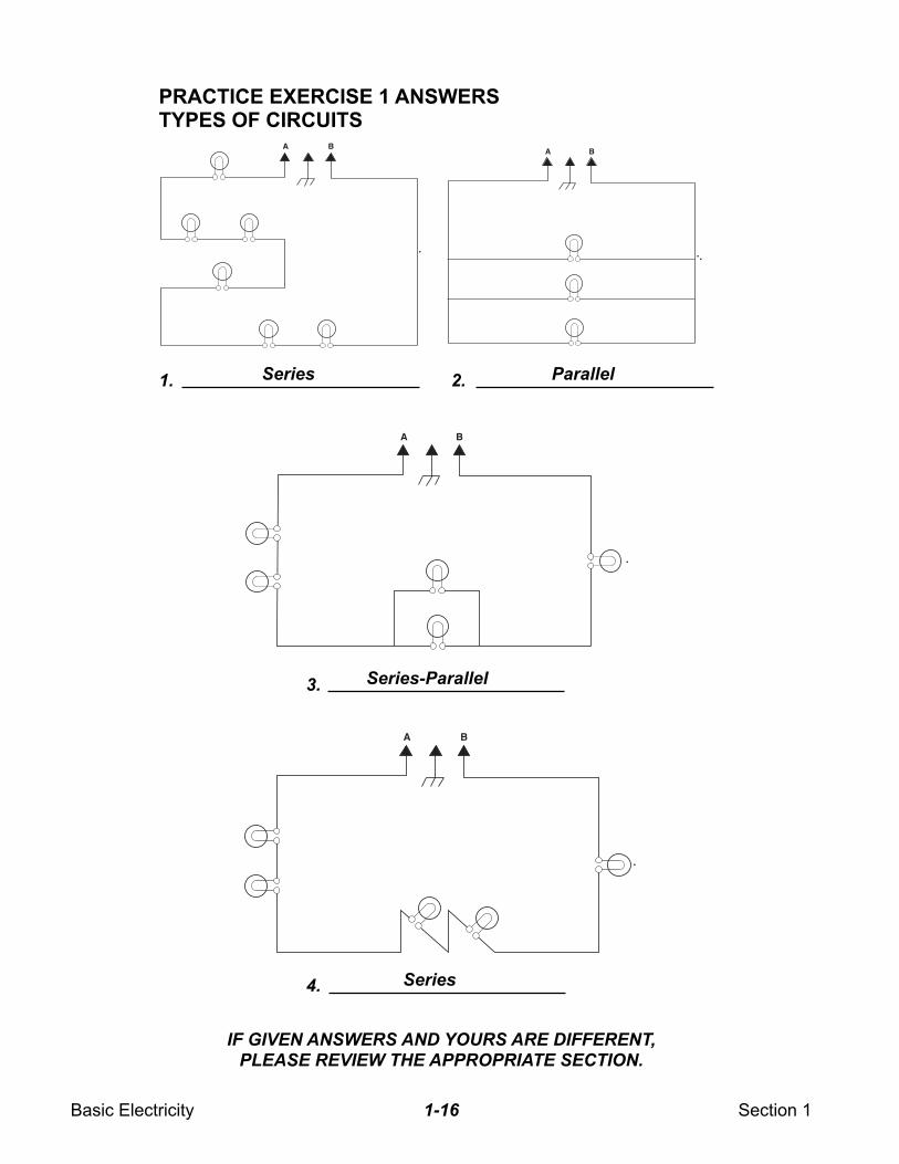
PRACTICE EXERCISE 1 ANSWERSTYPES OF CIRCUITS
IF GIVEN ANSWERS AND YOURS ARE DIFFERENT,PLEASE REVIEW THE APPROPRIATE SECTION.
A BA B
A B
A B
1. 2.
3.
4.
Series Parallel
Series-Parallel
Series
Basic Electricity Section 11-17
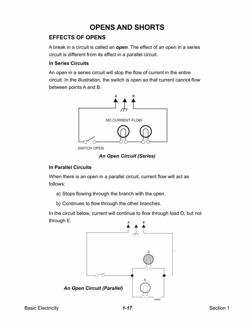
OPENS AND SHORTS
EFFECTS OF OPENS
A break in a circuit is called an open. The effect of an open in a series
circuit is different from its effect in a parallel circuit.
In Series Circuits
An open in a series circuit will stop the flow of current in the entire
circuit. In the illustration, the switch is open so that current cannot flow
between points A and B.
In Parallel Circuits
When there is an open in a parallel circuit, current flow will act as
follows:
a) Stops flowing through the branch with the open.
b) Continues to flow through the other branches.
In the circuit below, current will continue to flow through load D, but not
through E.
A B
SWITCH OPEN
NO CURRENT FLOW
A B
OPEN
E
D
An Open Circuit (Series)
An Open Circuit (Parallel)
Basic Electricity Section 11-18
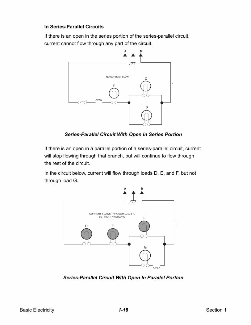
In Series-Parallel Circuits
If there is an open in the series portion of the series-parallel circuit,
current cannot flow through any part of the circuit.
If there is an open in a parallel portion of a series-parallel circuit, current
will stop flowing through that branch, but will continue to flow through
the rest of the circuit.
In the circuit below, current will flow through loads D, E, and F, but not
through load G.
A B
OPEN
NO CURRENT FLOW
D
C
E
Series-Parallel Circuit With Open In Series Portion
A B
CURRENT FLOWS THROUGH D, E, & F,BUT NOT THROUGH G
OPEN
G
F
ED
Series-Parallel Circuit With Open In Parallel Portion
Basic Electricity Section 11-19
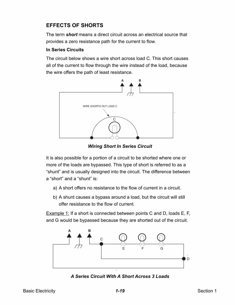
EFFECTS OF SHORTS
The term short means a direct circuit across an electrical source that
provides a zero resistance path for the current to flow.
In Series Circuits
The circuit below shows a wire short across load C. This short causes
all of the current to flow through the wire instead of the load, because
the wire offers the path of least resistance.
It is also possible for a portion of a circuit to be shorted where one or
more of the loads are bypassed. This type of short is referred to as a
“shunt” and is usually designed into the circuit. The difference between
a “short” and a “shunt” is:
a) A short offers no resistance to the flow of current in a circuit.
b) A shunt causes a bypass around a load, but the circuit will still
offer resistance to the flow of current.
Example 1: If a short is connected between points C and D, loads E, F,
and G would be bypassed because they are shorted out of the circuit.
A B
WIRE SHORTS OUT LOAD C
C
Wiring Short In Series Circuit
A B
E
C
D
F G
A Series Circuit With A Short Across 3 Loads
Basic Electricity Section 11-20
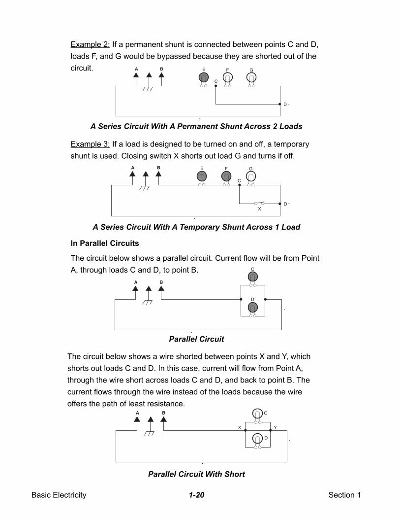
Example 2: If a permanent shunt is connected between points C and D,
loads F, and G would be bypassed because they are shorted out of the
circuit.
In Parallel Circuits
The circuit below shows a parallel circuit. Current flow will be from Point
A, through loads C and D, to point B.
Example 3: If a load is designed to be turned on and off, a temporary
shunt is used. Closing switch X shorts out load G and turns if off.
The circuit below shows a wire shorted between points X and Y, which
shorts out loads C and D. In this case, current will flow from Point A,
through the wire short across loads C and D, and back to point B. The
current flows through the wire instead of the loads because the wire
offers the path of least resistance.
A Series Circuit With A Permanent Shunt Across 2 Loads
A Series Circuit With A Temporary Shunt Across 1 Load
Parallel Circuit
Parallel Circuit With Short
A B C
D
YX
A B E
D
F
C
G
A B E
D
F
C
X
G
A B
C
D
Basic Electricity Section 11-21
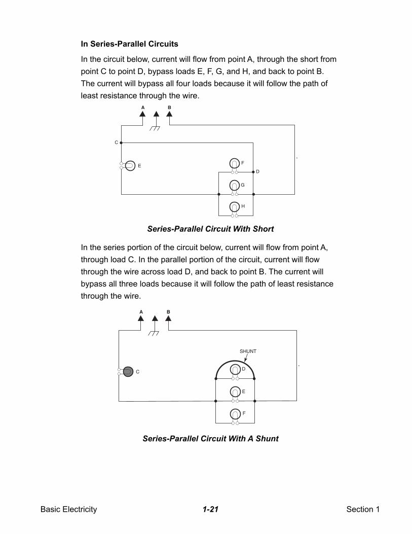
In Series-Parallel Circuits
In the circuit below, current will flow from point A, through the short from
point C to point D, bypass loads E, F, G, and H, and back to point B.
The current will bypass all four loads because it will follow the path of
least resistance through the wire.
In the series portion of the circuit below, current will flow from point A,
through load C. In the parallel portion of the circuit, current will flow
through the wire across load D, and back to point B. The current will
bypass all three loads because it will follow the path of least resistance
through the wire.
A B
FE
C
G
H
D
A B
DC
SHUNT
E
F
Series-Parallel Circuit With Short
Series-Parallel Circuit With A Shunt
Basic Electricity Section 11-22
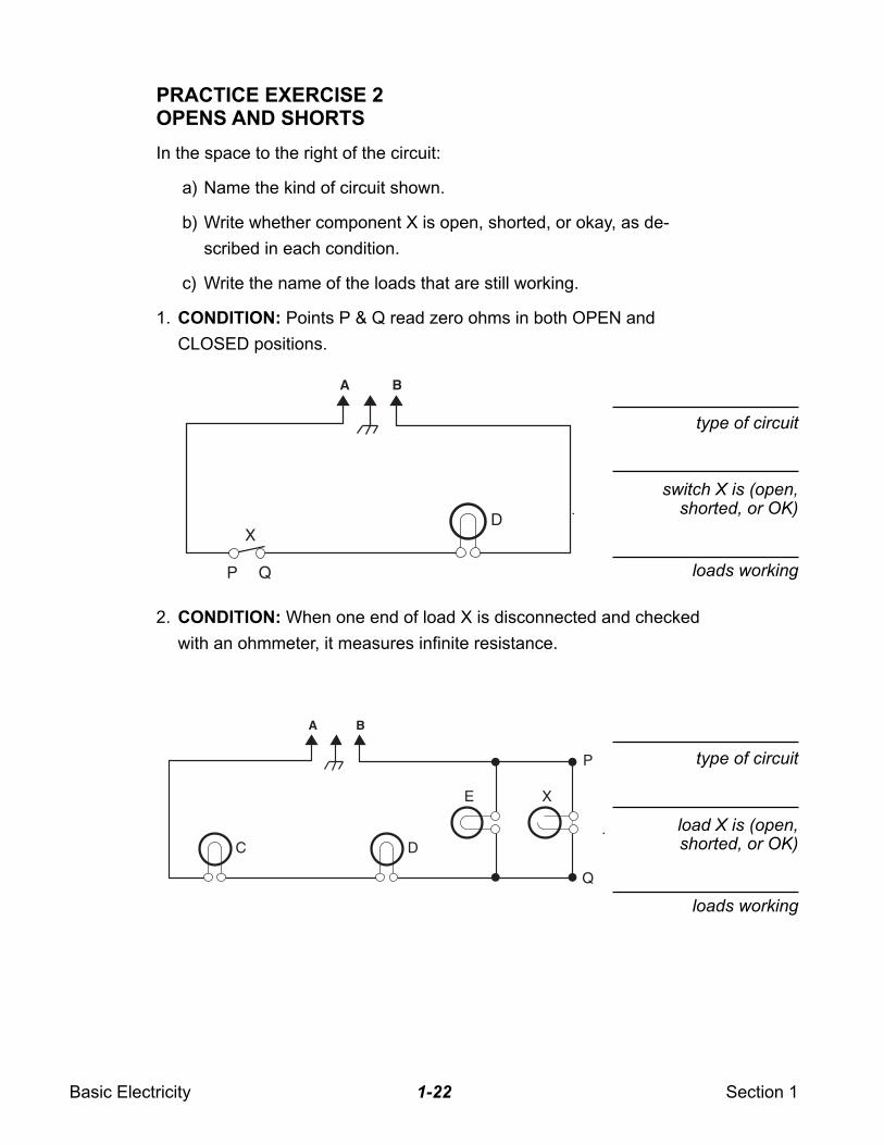
PRACTICE EXERCISE 2OPENS AND SHORTS
In the space to the right of the circuit:
a) Name the kind of circuit shown.
b) Write whether component X is open, shorted, or okay, as de-
scribed in each condition.
c) Write the name of the loads that are still working.
1. CONDITION: Points P & Q read zero ohms in both OPEN and
CLOSED positions.
2. CONDITION: When one end of load X is disconnected and checked
with an ohmmeter, it measures infinite resistance.
A B
DX
P Q
type of circuit
switch X is (open,shorted, or OK)
loads working
A B
C D
E X
P
Q
type of circuit
load X is (open,shorted, or OK)
loads working
Basic Electricity Section 11-23
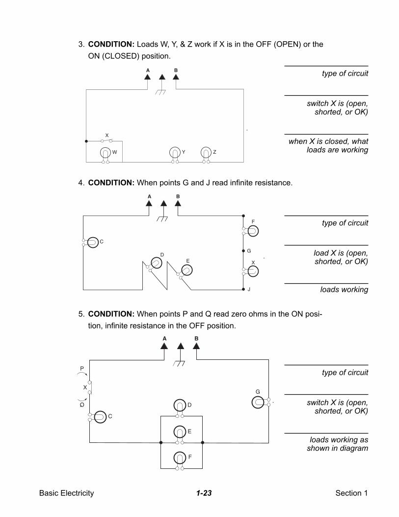
3. CONDITION: Loads W, Y, & Z work if X is in the OFF (OPEN) or the
ON (CLOSED) position.
4. CONDITION: When points G and J read infinite resistance.
5. CONDITION: When points P and Q read zero ohms in the ON posi-
tion, infinite resistance in the OFF position.
type of circuit
switch X is (open,shorted, or OK)
type of circuit
load X is (open,shorted, or OK)
loads working
type of circuit
switch X is (open,shorted, or OK)
when X is closed, whatloads are working
A B
Y ZW
X
A B
D
C
F
G
J
XE
A B
C
X
P
Q D
G
E
F
loads working asshown in diagram
Basic Electricity Section 11-24
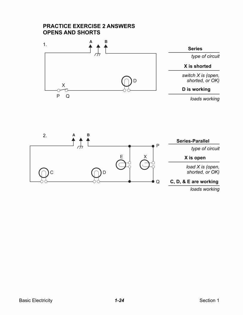
PRACTICE EXERCISE 2 ANSWERSOPENS AND SHORTS
switch X is (open,shorted, or OK)
loads working
type of circuit
load X is (open,shorted, or OK)
loads working
Series
X is shorted
type of circuit
D is working
X is open
Series-Parallel
C, D, & E are working
A B
DX
P Q
A B
C D
E X
P
Q
1.
2.
Basic Electricity Section 11-25
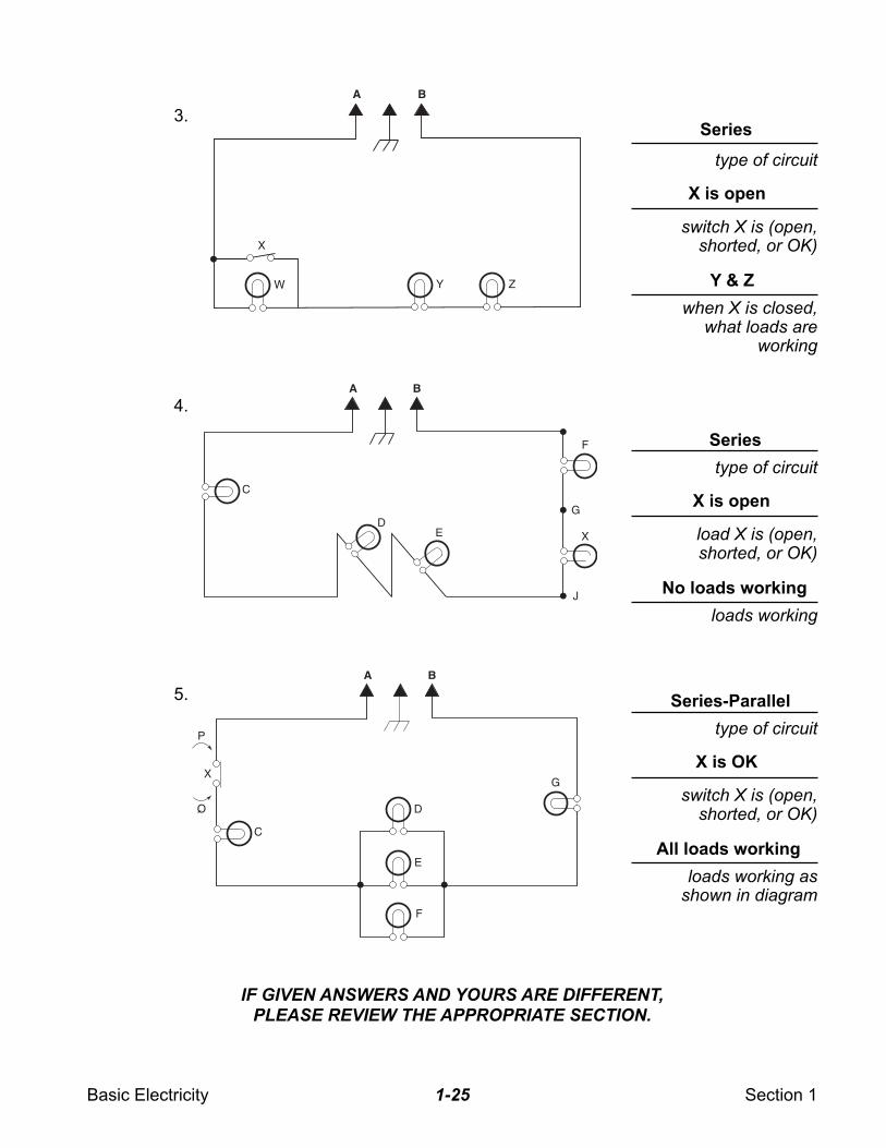
3.
4.
5.
A B
Y ZW
X
type of circuit
switch X is (open,shorted, or OK)
when X is closed,what loads are
working
X is open
Series
Y & Z
A B
D
C
F
G
J
XE
type of circuit
load X is (open,shorted, or OK)
loads working
X is open
Series
No loads working
A B
C
X
P
Q D
G
E
F
type of circuit
switch X is (open,shorted, or OK)
loads working asshown in diagram
X is OK
Series-Parallel
All loads working
IF GIVEN ANSWERS AND YOURS ARE DIFFERENT,PLEASE REVIEW THE APPROPRIATE SECTION.

Basic Electricity Section 11-26
— NOTES —
Wiring Diagrams Section 22-1
SECTION 2
WIRING DIAGRAMS
INTRODUCTION
A wiring diagram is a convenient way of showing which components are
present in an appliance, and how those components are connected
together electrically.
Just as a road map helps you to get where you’re going, a wiring dia-
gram helps you follow current flow and identify problems.
It is important to realize that wiring diagrams, or “schematics,” identify
electrical connections and current flow, but they do not represent actual
locations, distances apart, or component placement (unless noted on
the drawing). Nor are they drawn to scale. They do tell you what compo-
nents are used and how the electricity should flow.
In this section we will be reviewing wiring diagrams for a typical range,
dishwasher, and microwave oven.
Wiring Diagrams Section 22-2
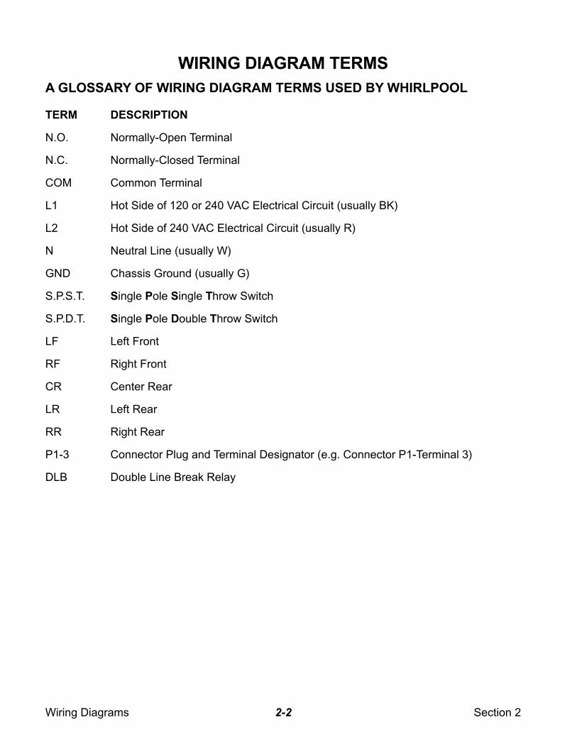
WIRING DIAGRAM TERMS
A GLOSSARY OF WIRING DIAGRAM TERMS USED BY WHIRLPOOL
TERM DESCRIPTION
N.O. Normally-Open Terminal
N.C. Normally-Closed Terminal
COM Common Terminal
L1 Hot Side of 120 or 240 VAC Electrical Circuit (usually BK)
L2 Hot Side of 240 VAC Electrical Circuit (usually R)
N Neutral Line (usually W)
GND Chassis Ground (usually G)
S.P.S.T. Single Pole Single Throw Switch
S.P.D.T. Single Pole Double Throw Switch
LF Left Front
RF Right Front
CR Center Rear
LR Left Rear
RR Right Rear
P1-3 Connector Plug and Terminal Designator (e.g. Connector P1-Terminal 3)
DLB Double Line Break Relay
Wiring Diagrams Section 22-3
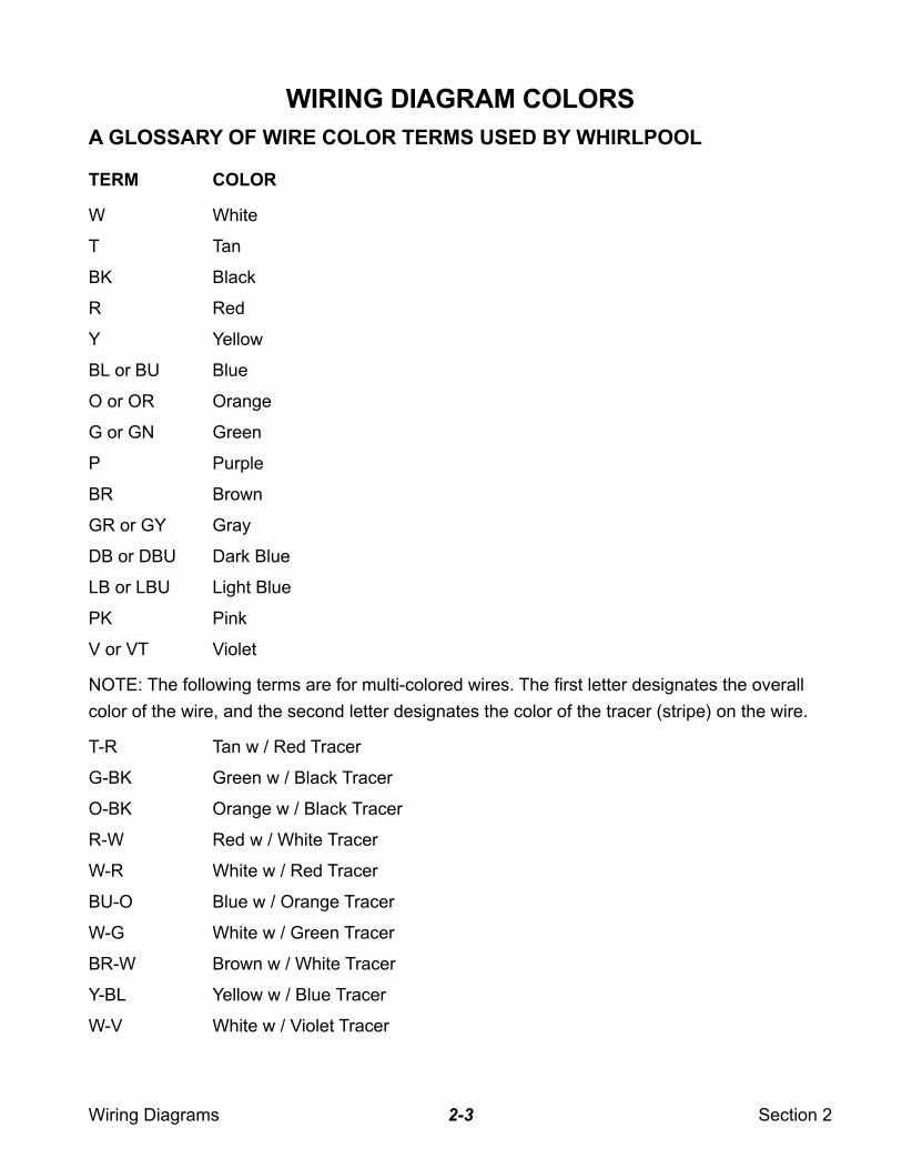
WIRING DIAGRAM COLORS
A GLOSSARY OF WIRE COLOR TERMS USED BY WHIRLPOOL
TERM COLOR
W White
T Tan
BK Black
R Red
Y Yellow
BL or BU Blue
O or OR Orange
G or GN Green
P Purple
BR Brown
GR or GY Gray
DB or DBU Dark Blue
LB or LBU Light Blue
PK Pink
V or VT Violet
NOTE: The following terms are for multi-colored wires. The first letter designates the overall
color of the wire, and the second letter designates the color of the tracer (stripe) on the wire.
T-R Tan w / Red Tracer
G-BK Green w / Black Tracer
O-BK Orange w / Black Tracer
R-W Red w / White Tracer
W-R White w / Red Tracer
BU-O Blue w / Orange Tracer
W-G White w / Green Tracer
BR-W Brown w / White Tracer
Y-BL Yellow w / Blue Tracer
W-V White w / Violet Tracer
Wiring Diagrams Section 22-4
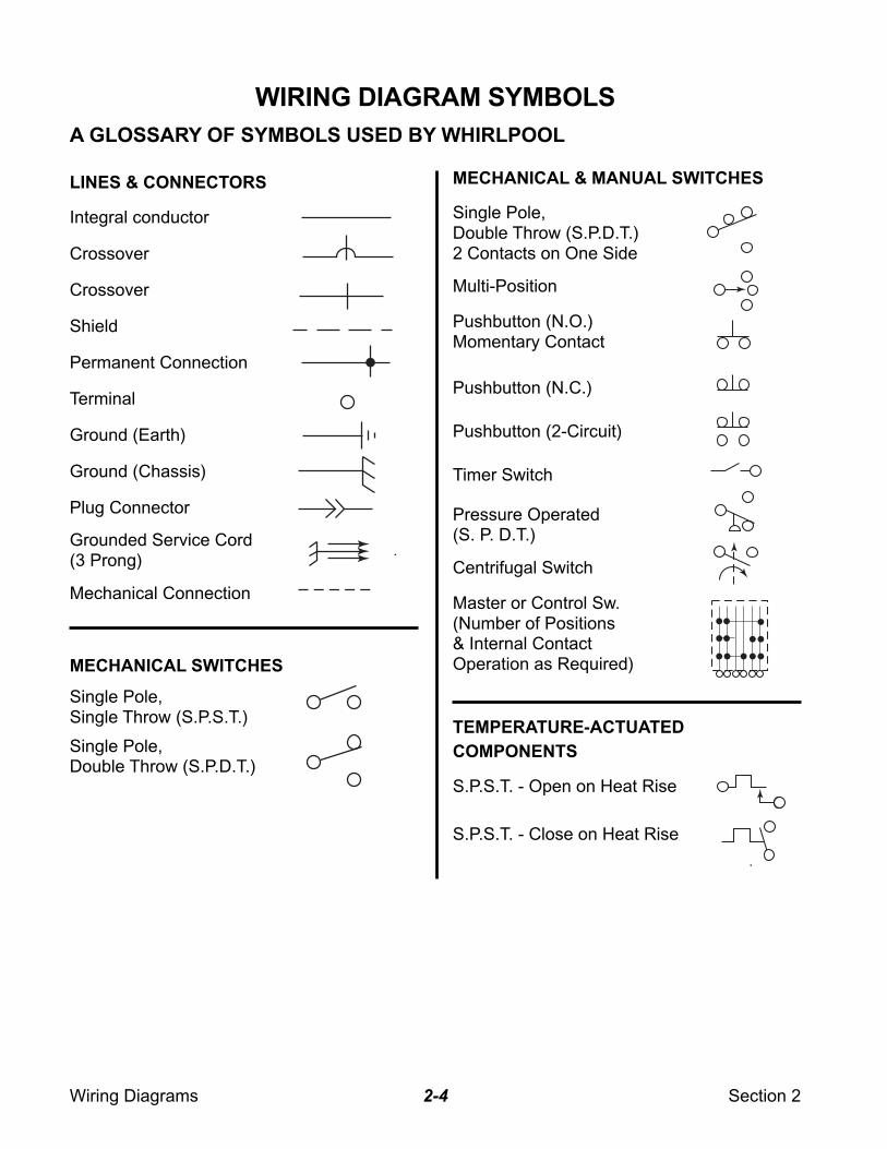
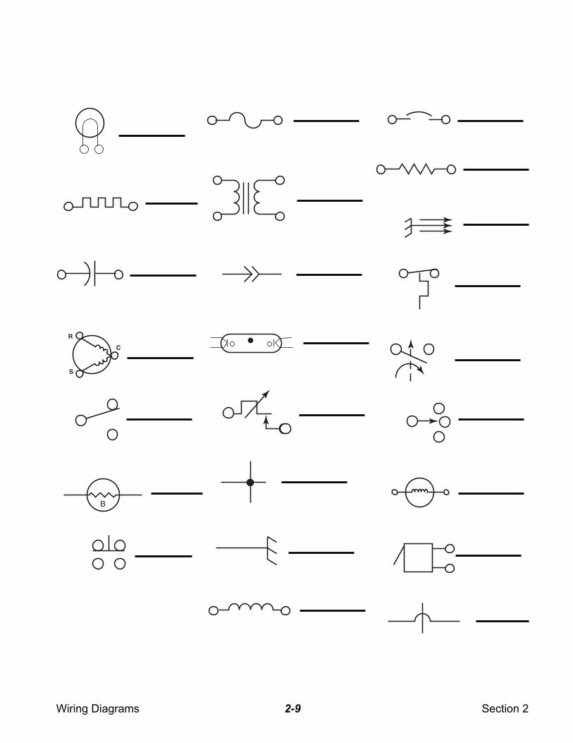
WIRING DIAGRAM SYMBOLS
A GLOSSARY OF SYMBOLS USED BY WHIRLPOOL
LINES & CONNECTORS MECHANICAL & MANUAL SWITCHES
Integral conductor
Crossover
Crossover
Shield
Permanent Connection
Terminal
Ground (Earth)
Ground (Chassis)
Plug Connector
Grounded Service Cord(3 Prong)
Mechanical Connection
MECHANICAL SWITCHES
Single Pole,Single Throw (S.P.S.T.)
Single Pole,Double Throw (S.P.D.T.)
Single Pole,Double Throw (S.P.D.T.)2 Contacts on One Side
Multi-Position
Pushbutton (N.O.)Momentary Contact
Pushbutton (N.C.)
Pushbutton (2-Circuit)
Timer Switch
Pressure Operated(S. P. D.T.)
Centrifugal Switch
Master or Control Sw.(Number of Positions& Internal ContactOperation as Required)
TEMPERATURE-ACTUATED
COMPONENTS
S.P.S.T. - Open on Heat Rise
S.P.S.T. - Close on Heat Rise
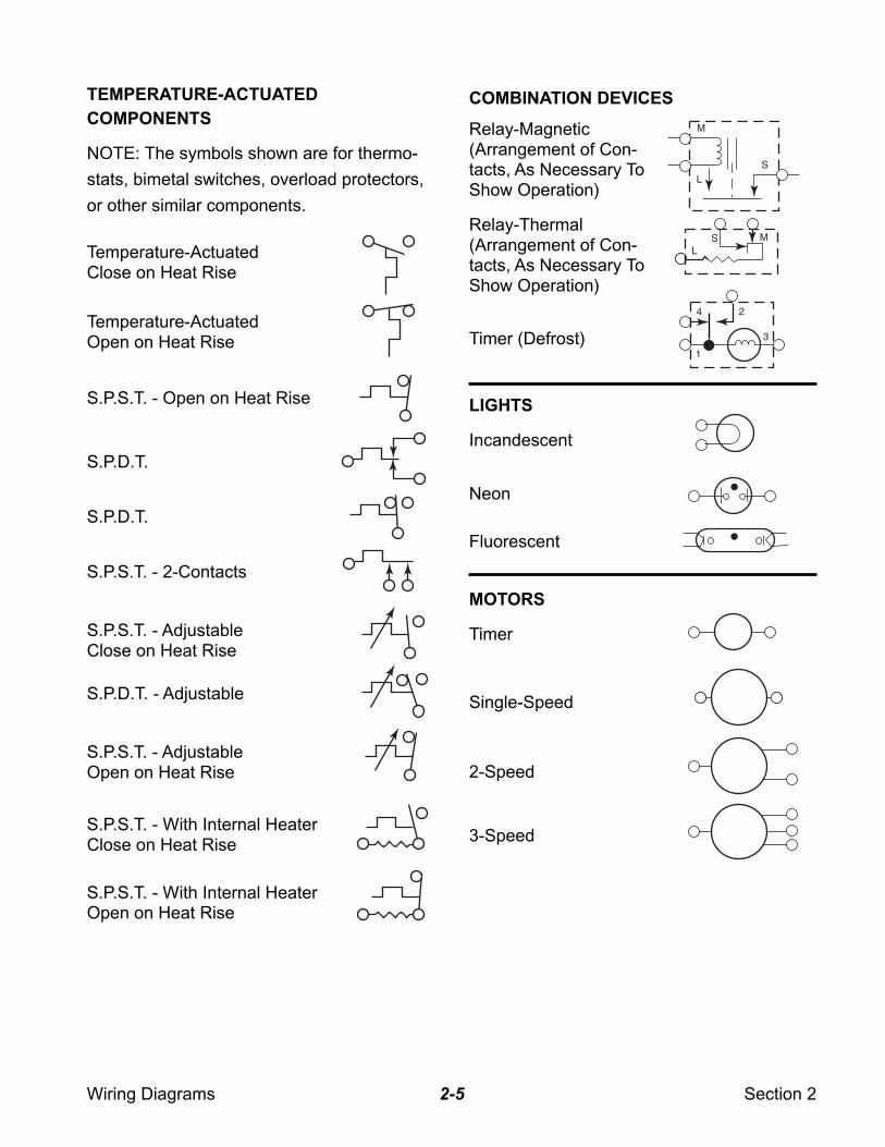
Wiring Diagrams Section 22-5
COMBINATION DEVICES
Relay-Magnetic(Arrangement of Con-tacts, As Necessary ToShow Operation)
M
LS
SL
M
4 2
3
1
TEMPERATURE-ACTUATED
COMPONENTS
NOTE: The symbols shown are for thermo-
stats, bimetal switches, overload protectors,
or other similar components.
Temperature-ActuatedOpen on Heat Rise
Temperature-ActuatedClose on Heat Rise
S.P.S.T. - Open on Heat Rise
S.P.D.T.
S.P.D.T.
S.P.S.T. - 2-Contacts
S.P.S.T. - AdjustableClose on Heat Rise
S.P.D.T. - Adjustable
S.P.S.T. - AdjustableOpen on Heat Rise
S.P.S.T. - With Internal HeaterClose on Heat Rise
S.P.S.T. - With Internal HeaterOpen on Heat Rise
Relay-Thermal(Arrangement of Con-tacts, As Necessary ToShow Operation)
Timer (Defrost)
Fluorescent
LIGHTS
Incandescent
Neon
3-Speed
MOTORS
Timer
Single-Speed
2-Speed
Wiring Diagrams Section 22-6
B
s
+ –
OR
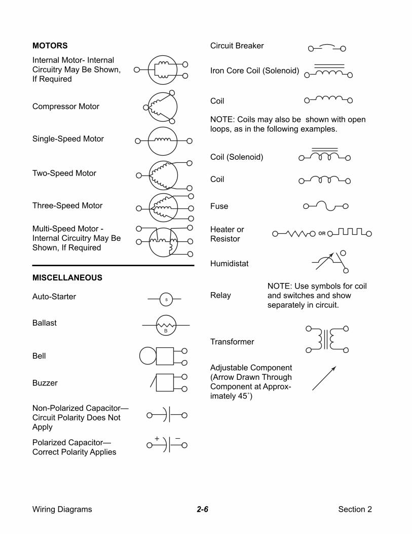
NOTE: Use symbols for coiland switches and showseparately in circuit.
MOTORS
Internal Motor- InternalCircuitry May Be Shown,If Required
Compressor Motor
Single-Speed Motor
Two-Speed Motor
Three-Speed Motor
Multi-Speed Motor -Internal Circuitry May BeShown, If Required
MISCELLANEOUS
Auto-Starter
Ballast
Bell
Buzzer
Polarized Capacitor—Correct Polarity Applies
Circuit Breaker
Iron Core Coil (Solenoid)
Coil
NOTE: Coils may also be shown with openloops, as in the following examples.
Coil (Solenoid)
Coil
Fuse
Heater orResistor
Humidistat
Relay
Transformer
Adjustable Component(Arrow Drawn ThroughComponent at Approx-imately 45˚)
Non-Polarized Capacitor—Circuit Polarity Does NotApply
Wiring Diagrams Section 22-7
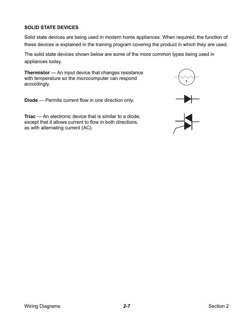
SOLID STATE DEVICES
Solid state devices are being used in modern home appliances. When required, the function of
these devices is explained in the training program covering the product in which they are used.
The solid state devices shown below are some of the more common types being used in
appliances today.
Thermistor — An input device that changes resistancewith temperature so the microcomputer can respondaccordingly.
Diode — Permits current flow in one direction only.
Triac — An electronic device that is similar to a diode,except that it allows current to flow in both directions,as with alternating current (AC).
T
Wiring Diagrams Section 22-8
PRACTICE EXERCISE 1IDENTIFYING COMPONENTS
Place the numbers on the lines beside the symbols on the next page to
make the proper match.
1. Compressor
2. Crossover
3. Ballast
4. Permanent Connection
5. Adjustable Buzzer
6. Incandescent Lamp
7. Fluorescent Lamp
8. Heat Rise Thermostat
9. Adjustable Thermostat
10. Chassis Ground
11. Transformer
12. Grounded Service Cord
13. Single-Pole, Double-Throw
(S.P.D.T.) Switch
14. Centrifugal Switch
15. Plug Connector
16. Resistor or Heater
17. Fuse
18. Multi-Position Switch
19. Coil
20. Circuit Breaker
21. Heater
22. Capacitor
23. Pushbutton (S.P.D.T.)
24. Single-Speed Motor
Wiring Diagrams Section 22-9
B
R
S
C
Wiring Diagrams Section 22-10
B
R
S
C
617 20
16
12
8
14
18
24
5
219
10
4
9
7
15
1121
22
1
13
3
23
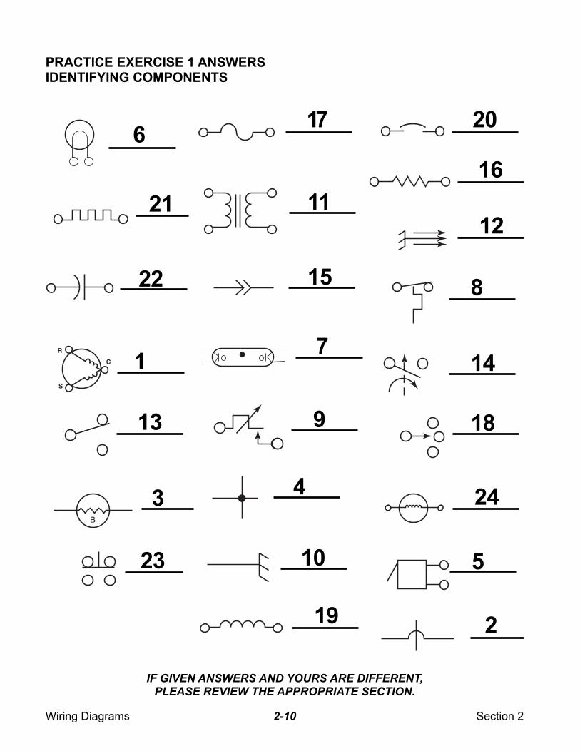
PRACTICE EXERCISE 1 ANSWERSIDENTIFYING COMPONENTS
IF GIVEN ANSWERS AND YOURS ARE DIFFERENT,
PLEASE REVIEW THE APPROPRIATE SECTION.
Wiring Diagrams Section 22-11
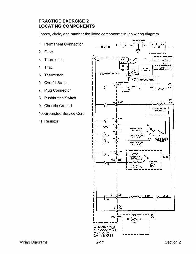
PRACTICE EXERCISE 2LOCATING COMPONENTS
Locate, circle, and number the listed components in the wiring diagram.
1. Permanent Connection
2. Fuse
3. Thermostat
4. Triac
5. Thermistor
6. Overfill Switch
7. Plug Connector
8. Pushbutton Switch
9. Chassis Ground
10.Grounded Service Cord
11. Resistor
Wiring Diagrams Section 22-12
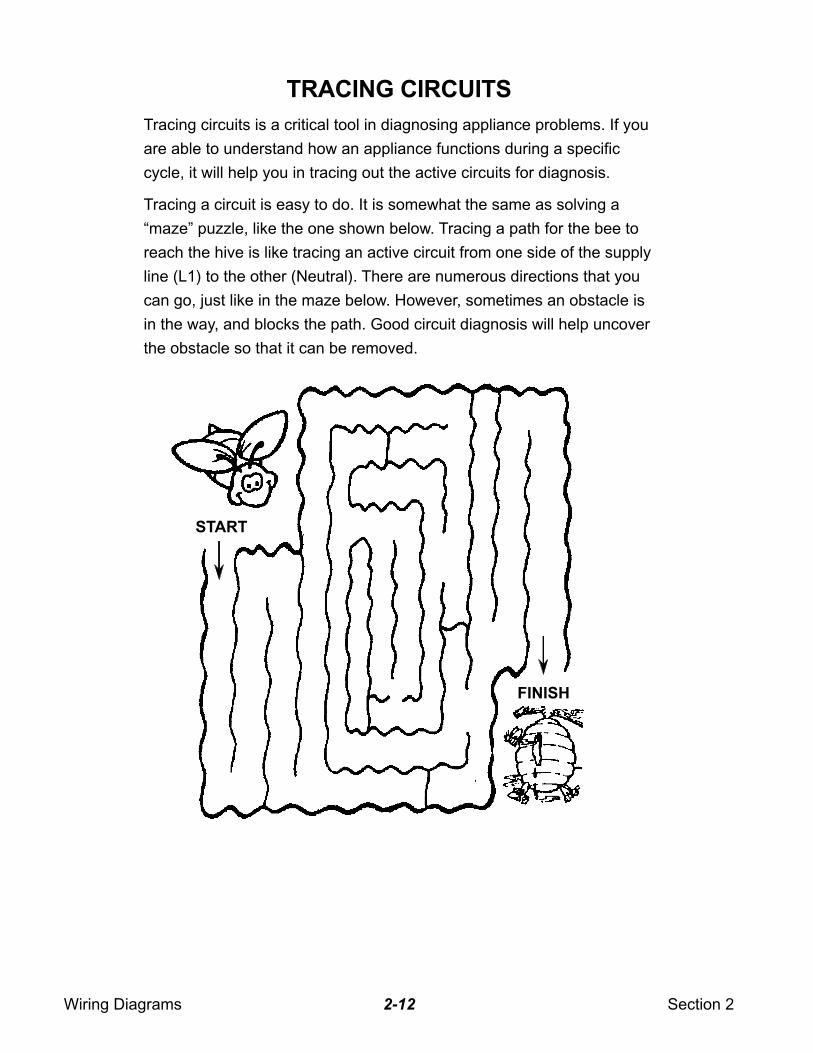
TRACING CIRCUITS
Tracing circuits is a critical tool in diagnosing appliance problems. If you
are able to understand how an appliance functions during a specific
cycle, it will help you in tracing out the active circuits for diagnosis.
Tracing a circuit is easy to do. It is somewhat the same as solving a
“maze” puzzle, like the one shown below. Tracing a path for the bee to
reach the hive is like tracing an active circuit from one side of the supply
line (L1) to the other (Neutral). There are numerous directions that you
can go, just like in the maze below. However, sometimes an obstacle is
in the way, and blocks the path. Good circuit diagnosis will help uncover
the obstacle so that it can be removed.
START
FINISH
Wiring Diagrams Section 22-13
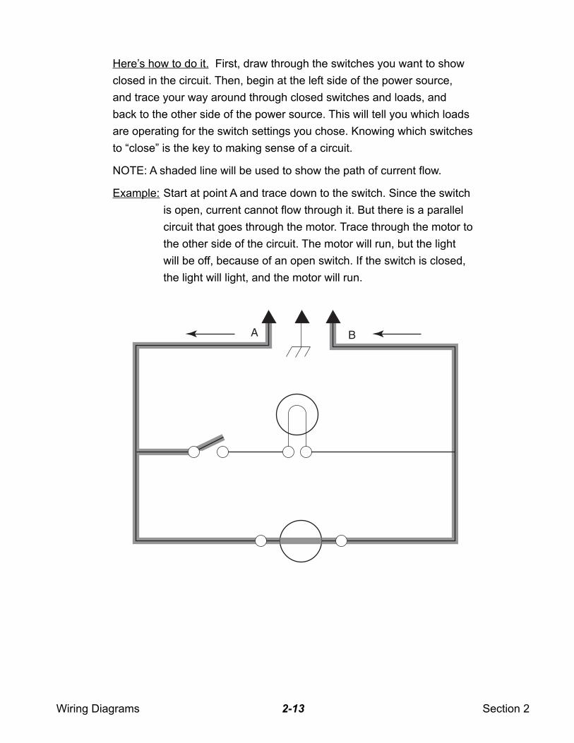
Here’s how to do it. First, draw through the switches you want to show
closed in the circuit. Then, begin at the left side of the power source,
and trace your way around through closed switches and loads, and
back to the other side of the power source. This will tell you which loads
are operating for the switch settings you chose. Knowing which switches
to “close” is the key to making sense of a circuit.
NOTE: A shaded line will be used to show the path of current flow.
Example: Start at point A and trace down to the switch. Since the switch
is open, current cannot flow through it. But there is a parallel
circuit that goes through the motor. Trace through the motor to
the other side of the circuit. The motor will run, but the light
will be off, because of an open switch. If the switch is closed,
the light will light, and the motor will run.
A B
Wiring Diagrams Section 22-14
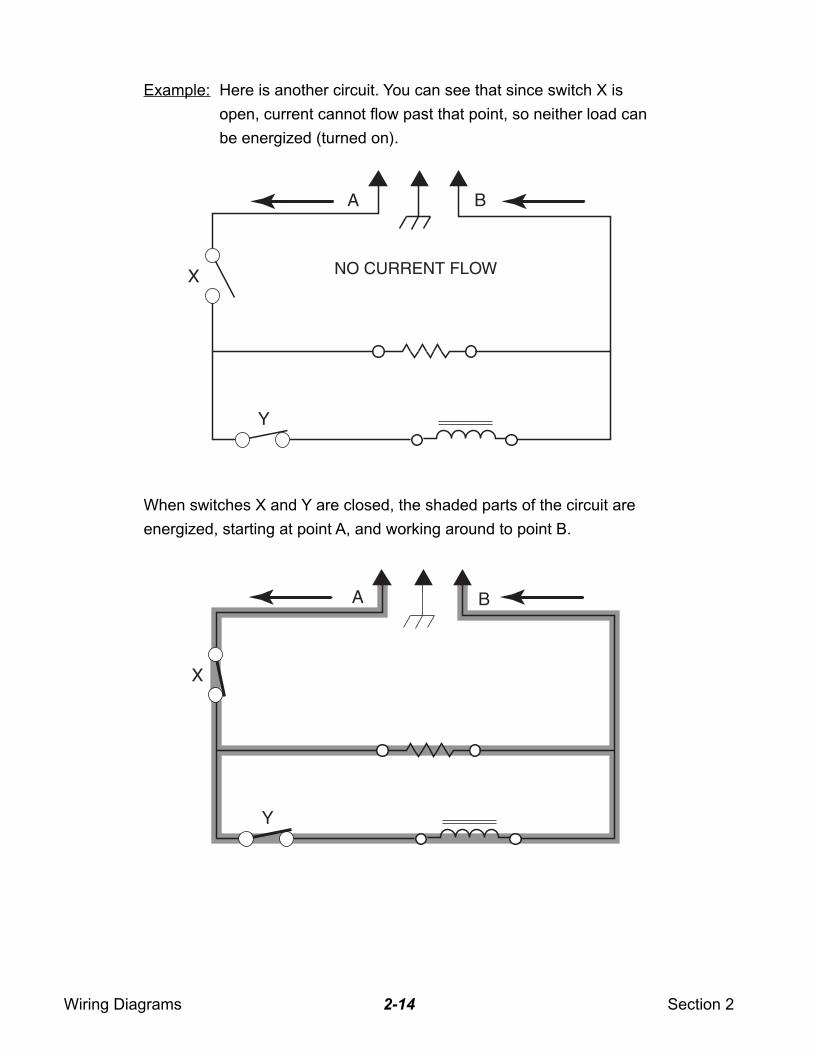
Example: Here is another circuit. You can see that since switch X is
open, current cannot flow past that point, so neither load can
be energized (turned on).
When switches X and Y are closed, the shaded parts of the circuit are
energized, starting at point A, and working around to point B.
NO CURRENT FLOWX
A B
Y
X
A B
Y
Wiring Diagrams Section 22-15
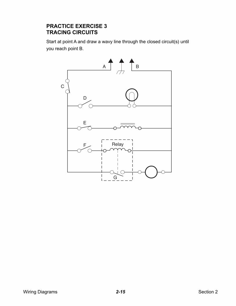
PRACTICE EXERCISE 3TRACING CIRCUITS
Start at point A and draw a wavy line through the closed circuit(s) until
you reach point B.
C
D
Relay
A B
E
F
G
Wiring Diagrams Section 22-16
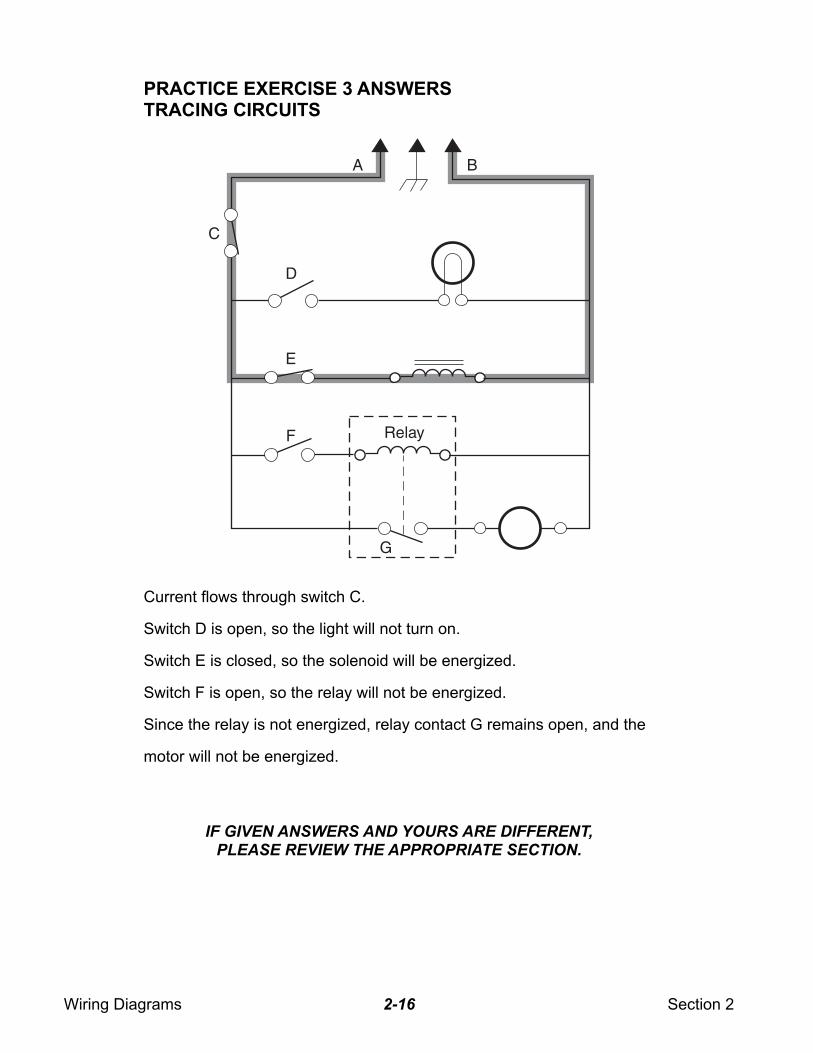
Current flows through switch C.
Switch D is open, so the light will not turn on.
Switch E is closed, so the solenoid will be energized.
Switch F is open, so the relay will not be energized.
Since the relay is not energized, relay contact G remains open, and the
motor will not be energized.
PRACTICE EXERCISE 3 ANSWERSTRACING CIRCUITS
C
D
Relay
A B
E
G
F
IF GIVEN ANSWERS AND YOURS ARE DIFFERENT,
PLEASE REVIEW THE APPROPRIATE SECTION.
Wiring Diagrams Section 22-17
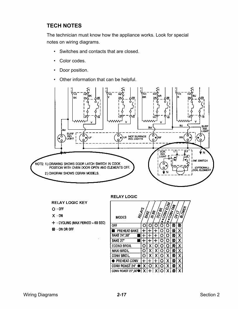
TECH NOTES
The technician must know how the appliance works. Look for special
notes on wiring diagrams.
• Switches and contacts that are closed.
• Color codes.
• Door position.
• Other information that can be helpful.
Wiring Diagrams Section 22-18
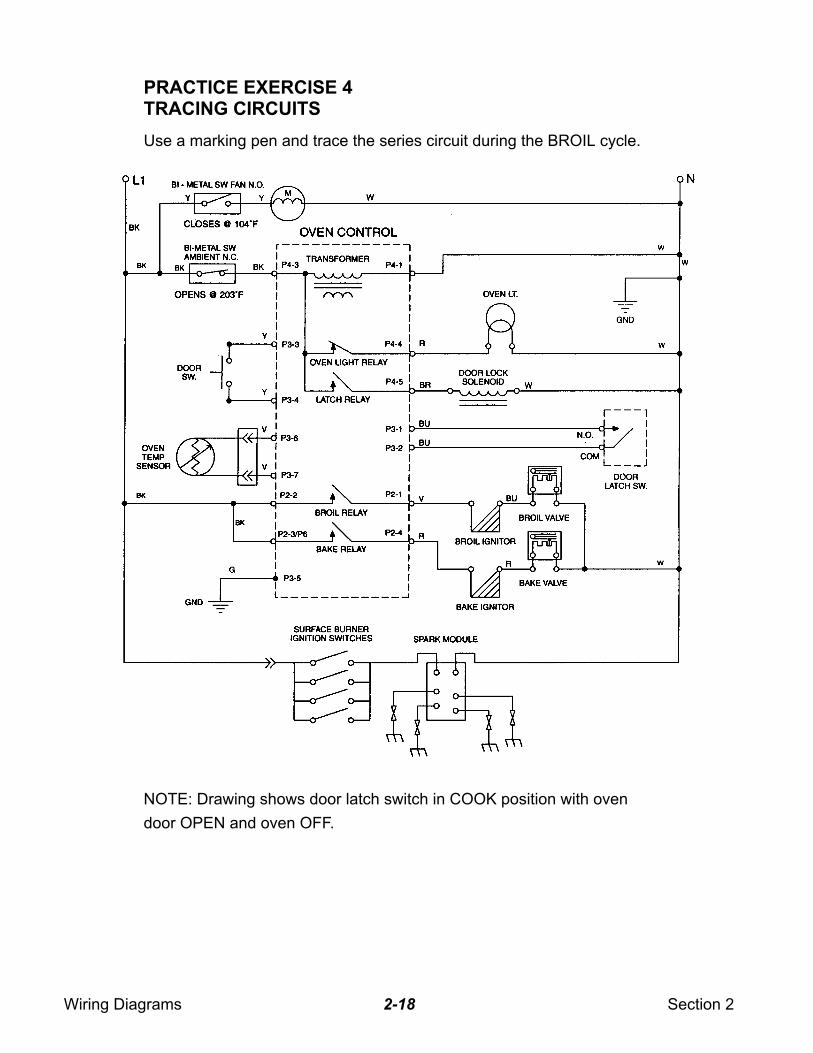
PRACTICE EXERCISE 4TRACING CIRCUITS
Use a marking pen and trace the series circuit during the BROIL cycle.
NOTE: Drawing shows door latch switch in COOK position with oven
door OPEN and oven OFF.

Wiring Diagrams Section 22-19
— NOTES —
Wiring Diagrams Section 22-20
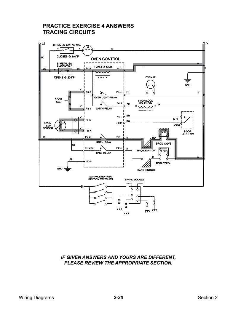
PRACTICE EXERCISE 4 ANSWERSTRACING CIRCUITS
IF GIVEN ANSWERS AND YOURS ARE DIFFERENT,
PLEASE REVIEW THE APPROPRIATE SECTION.
Wiring Diagrams Section 22-21
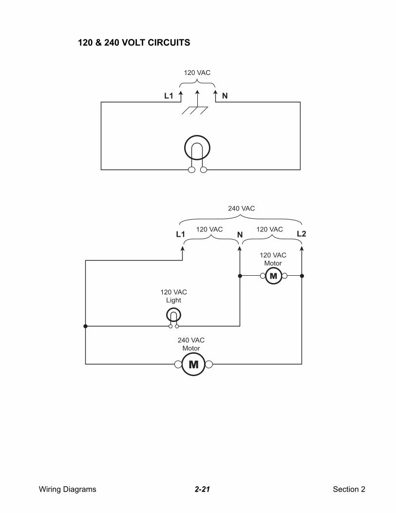
120 & 240 VOLT CIRCUITS
120 VAC
120 VAC 120 VAC
240 VAC
120 VAC
Motor
240 VAC
Motor
120 VAC
Light
L1
L1 L2N
N
M
M
Wiring Diagrams Section 22-22
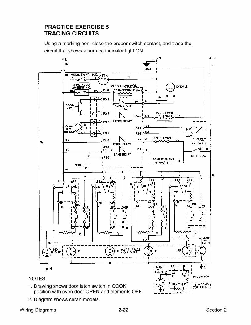
PRACTICE EXERCISE 5TRACING CIRCUITS
Using a marking pen, close the proper switch contact, and trace the
circuit that shows a surface indicator light ON.
NOTES:
1. Drawing shows door latch switch in COOK position with oven door OPEN and elements OFF.
2. Diagram shows ceran models.

Wiring Diagrams Section 22-23
— NOTES —
Wiring Diagrams Section 22-24
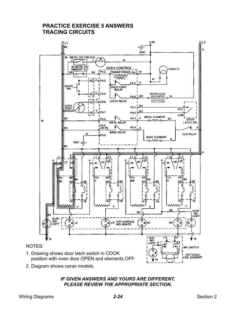
PRACTICE EXERCISE 5 ANSWERSTRACING CIRCUITS
NOTES:
1. Drawing shows door latch switch in COOK position with oven door OPEN and elements OFF.
2. Diagram shows ceran models.
IF GIVEN ANSWERS AND YOURS ARE DIFFERENT,
PLEASE REVIEW THE APPROPRIATE SECTION.
Wiring Diagrams Section 22-25
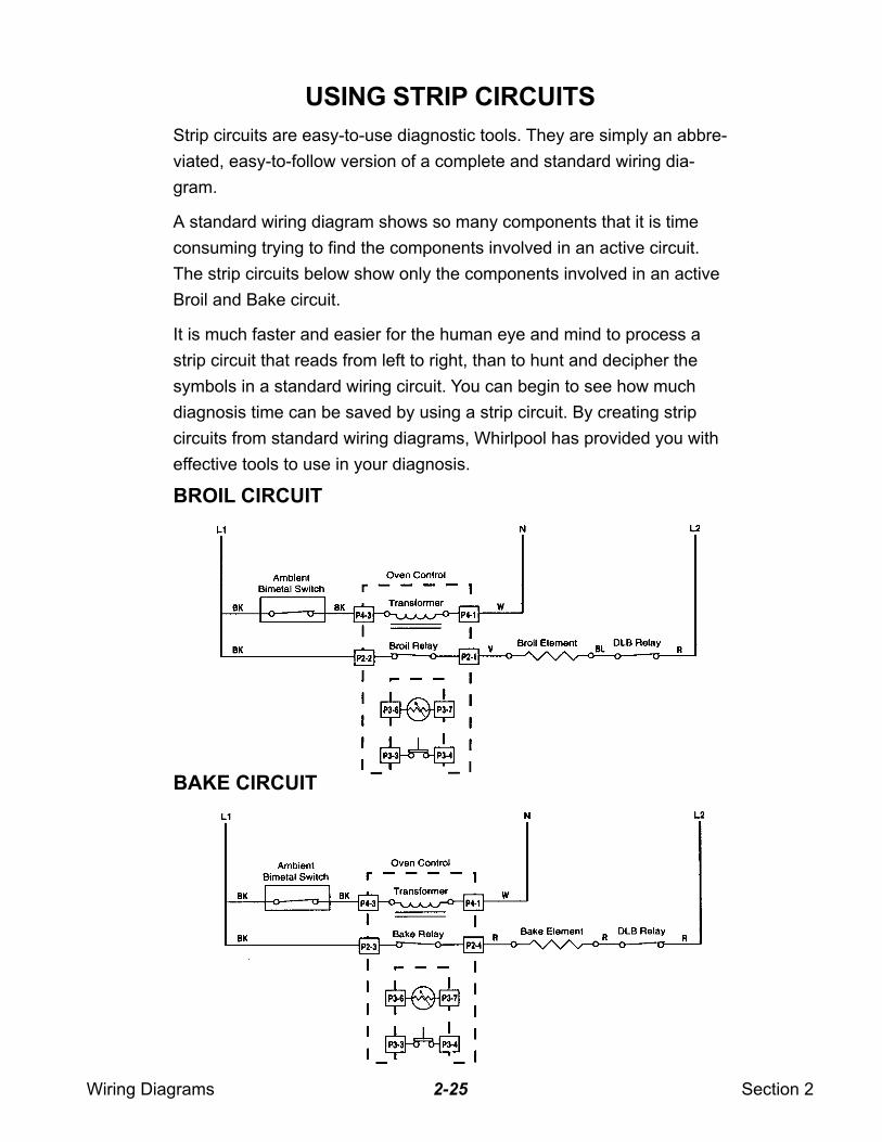
USING STRIP CIRCUITS
Strip circuits are easy-to-use diagnostic tools. They are simply an abbre-
viated, easy-to-follow version of a complete and standard wiring dia-
gram.
A standard wiring diagram shows so many components that it is time
consuming trying to find the components involved in an active circuit.
The strip circuits below show only the components involved in an active
Broil and Bake circuit.
It is much faster and easier for the human eye and mind to process a
strip circuit that reads from left to right, than to hunt and decipher the
symbols in a standard wiring circuit. You can begin to see how much
diagnosis time can be saved by using a strip circuit. By creating strip
circuits from standard wiring diagrams, Whirlpool has provided you with
effective tools to use in your diagnosis.
BROIL CIRCUIT
BAKE CIRCUIT
Wiring Diagrams Section 22-26
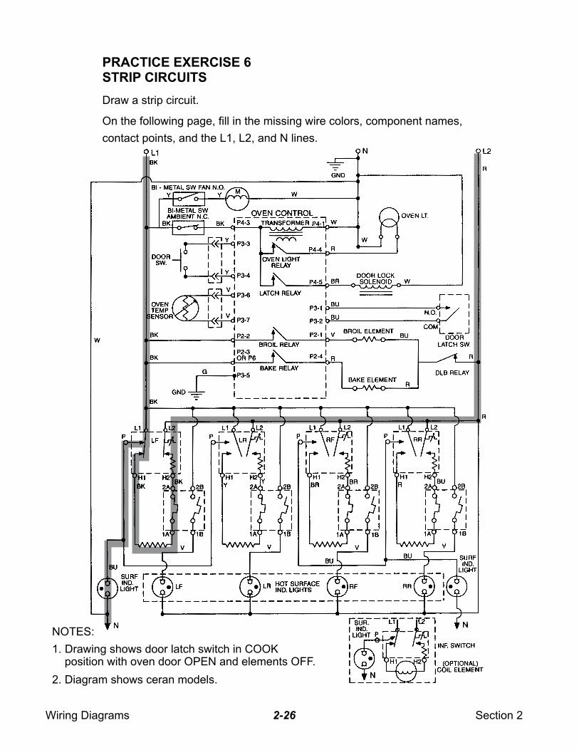
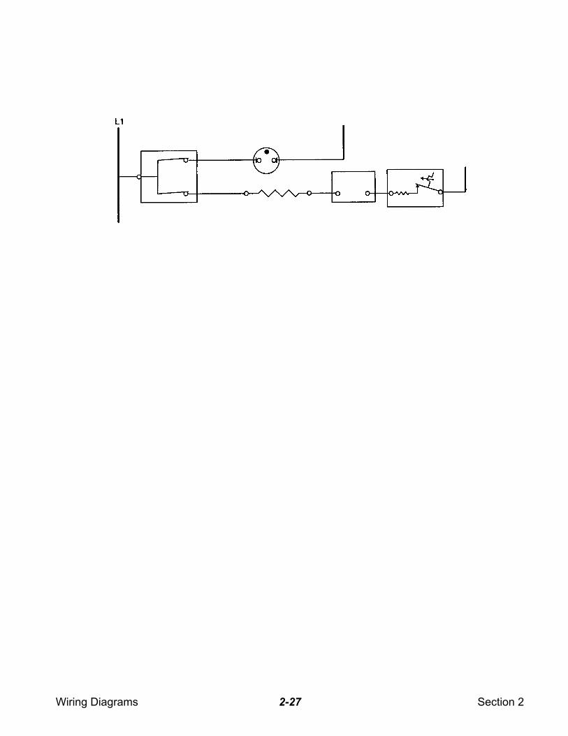
PRACTICE EXERCISE 6STRIP CIRCUITS
Draw a strip circuit.
On the following page, fill in the missing wire colors, component names,
contact points, and the L1, L2, and N lines.
NOTES:
1. Drawing shows door latch switch in COOK position with oven door OPEN and elements OFF.
2. Diagram shows ceran models.
Wiring Diagrams Section 22-27
Wiring Diagrams Section 22-28
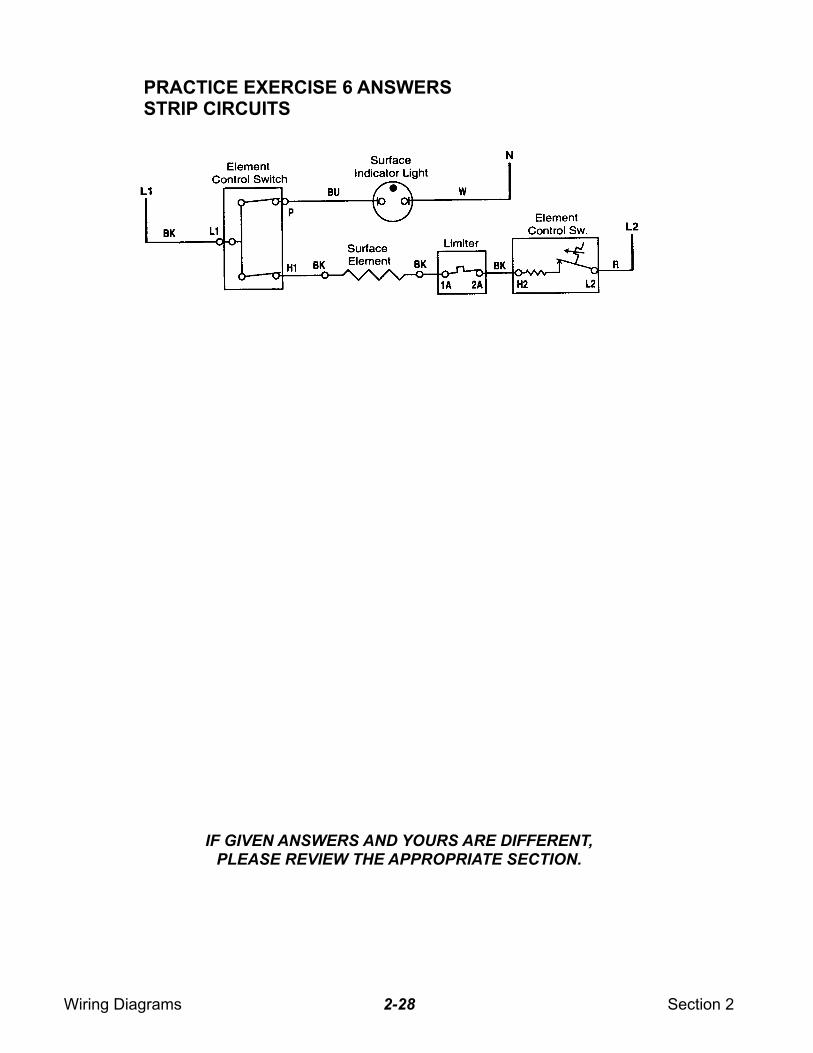
PRACTICE EXERCISE 6 ANSWERSSTRIP CIRCUITS
IF GIVEN ANSWERS AND YOURS ARE DIFFERENT,
PLEASE REVIEW THE APPROPRIATE SECTION.
Wiring Diagrams Section 22-29
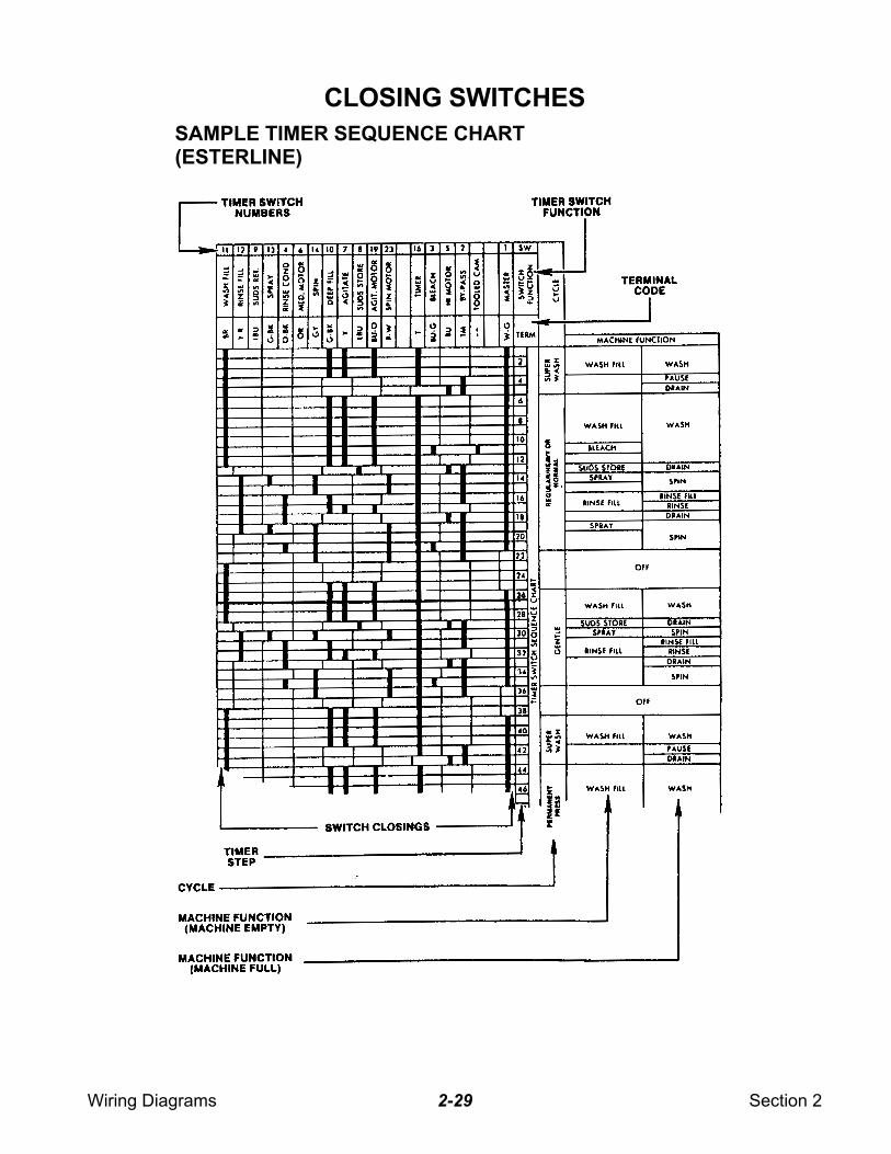
CLOSING SWITCHES
SAMPLE TIMER SEQUENCE CHART(ESTERLINE)
Wiring Diagrams Section 22-30
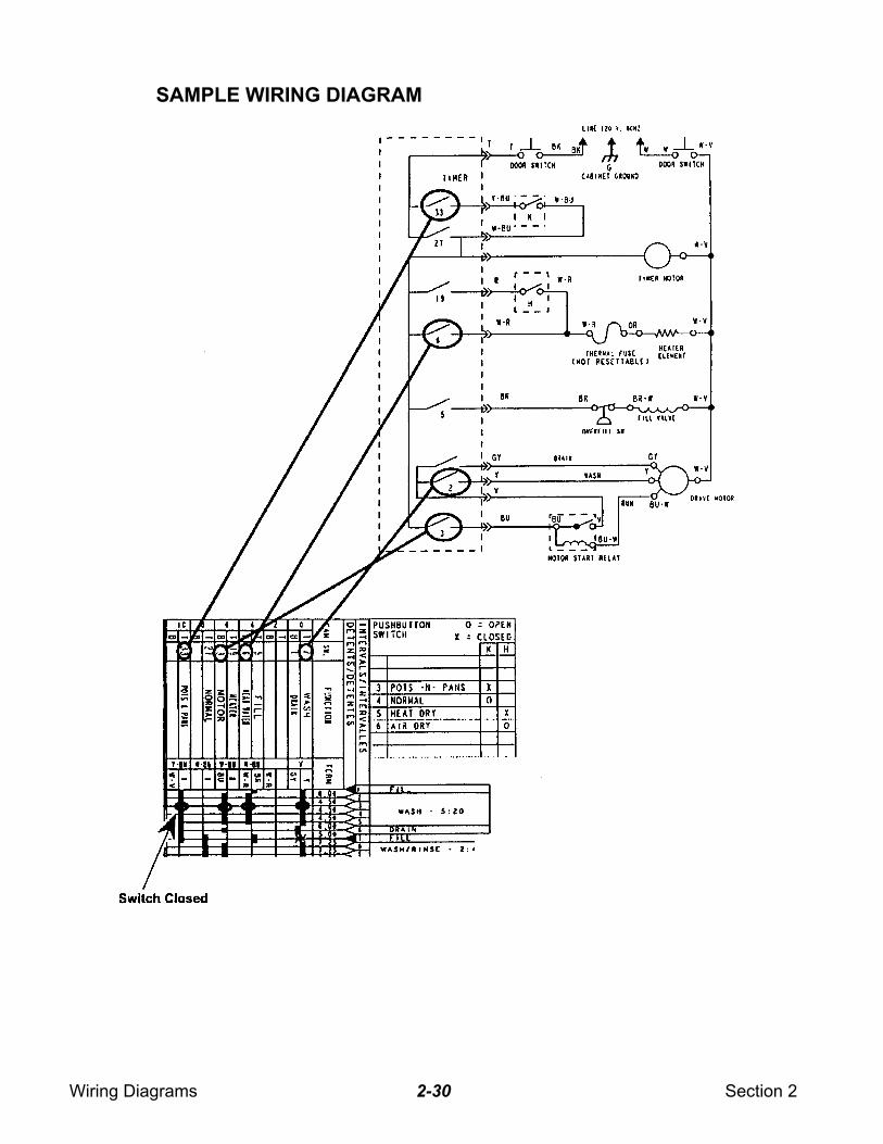
SAMPLE WIRING DIAGRAM

Wiring Diagrams Section 22-31
— NOTES —
Wiring Diagrams Section 22-32
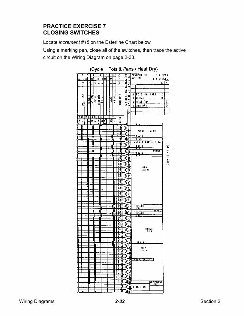
PRACTICE EXERCISE 7CLOSING SWITCHES
Locate increment #15 on the Esterline Chart below.
Using a marking pen, close all of the switches, then trace the active
circuit on the Wiring Diagram on page 2-33.
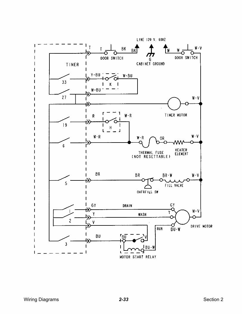
Wiring Diagrams Section 22-33
Wiring Diagrams Section 22-34
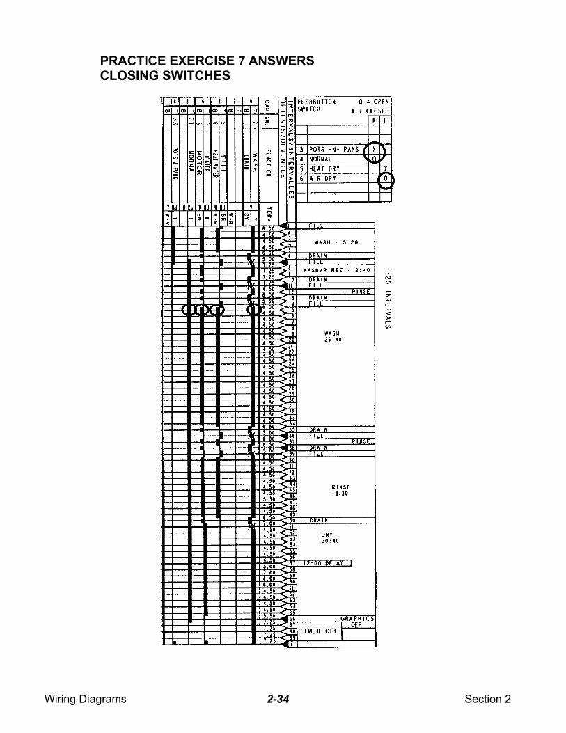
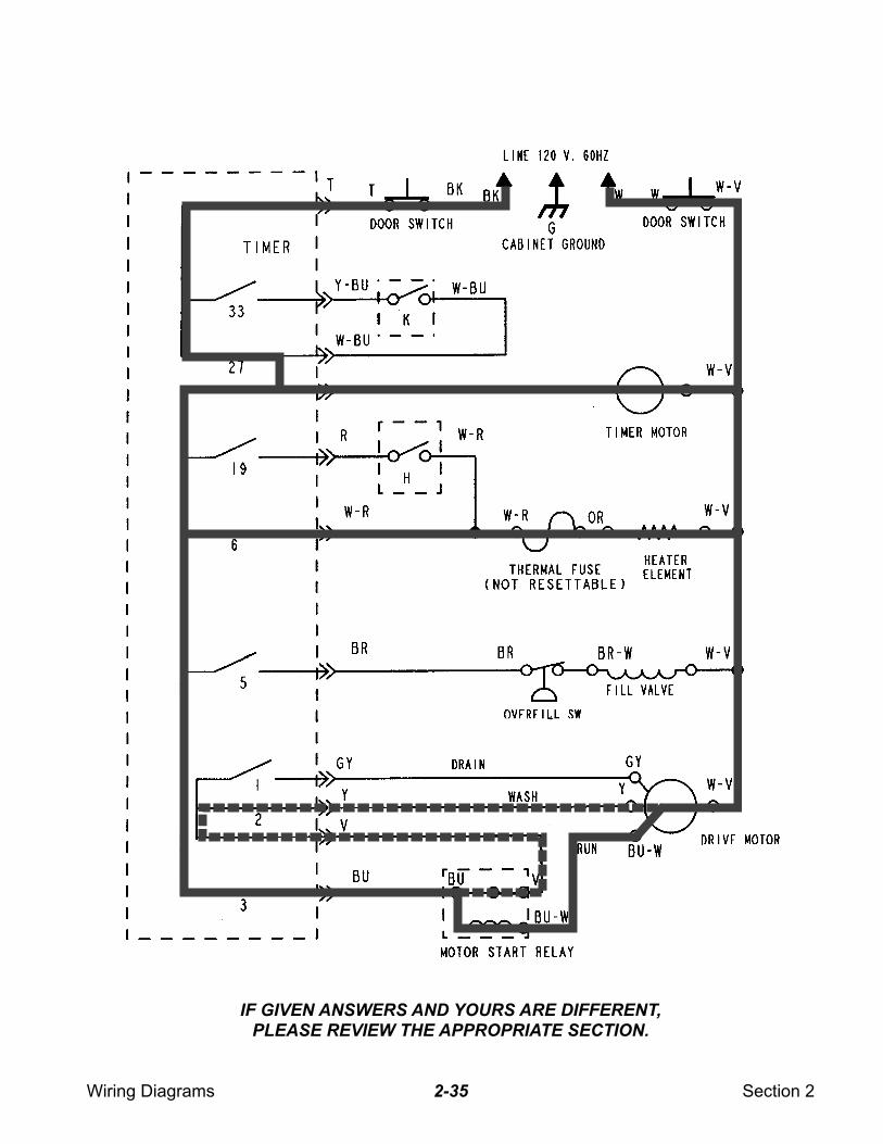
PRACTICE EXERCISE 7 ANSWERSCLOSING SWITCHES
Wiring Diagrams Section 22-35
IF GIVEN ANSWERS AND YOURS ARE DIFFERENT,
PLEASE REVIEW THE APPROPRIATE SECTION.
Wiring Diagrams Section 22-36
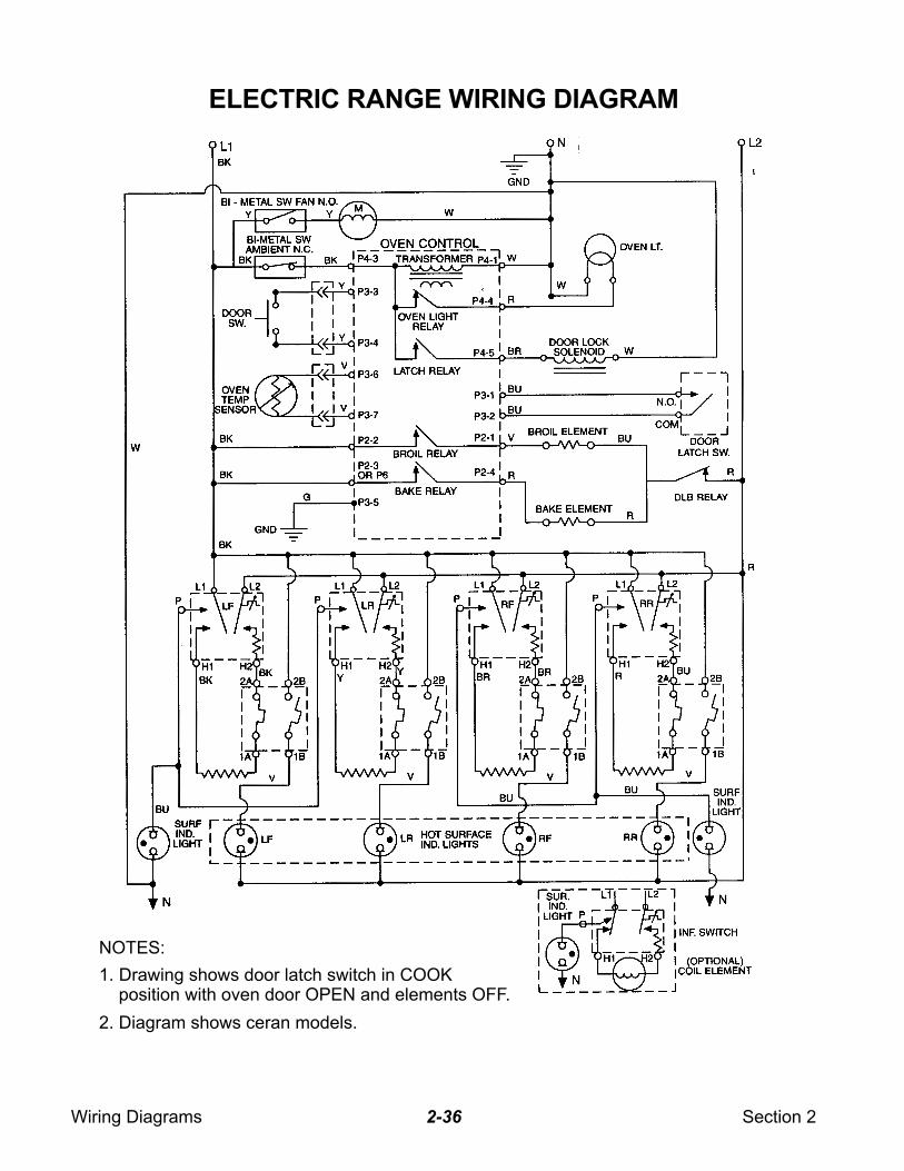
ELECTRIC RANGE WIRING DIAGRAM
NOTES:
1. Drawing shows door latch switch in COOK position with oven door OPEN and elements OFF.
2. Diagram shows ceran models.
Wiring Diagrams Section 22-37
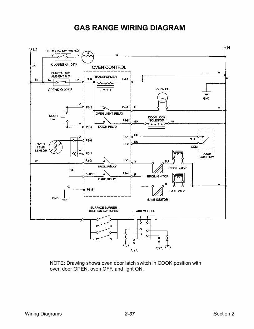
GAS RANGE WIRING DIAGRAM
NOTE: Drawing shows oven door latch switch in COOK position withoven door OPEN, oven OFF, and light ON.
Wiring Diagrams Section 22-38
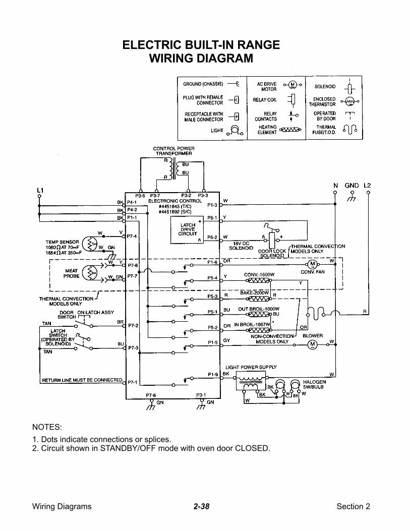
ELECTRIC BUILT-IN RANGEWIRING DIAGRAM
NOTES:
1. Dots indicate connections or splices.2. Circuit shown in STANDBY/OFF mode with oven door CLOSED.
Wiring Diagrams Section 22-39
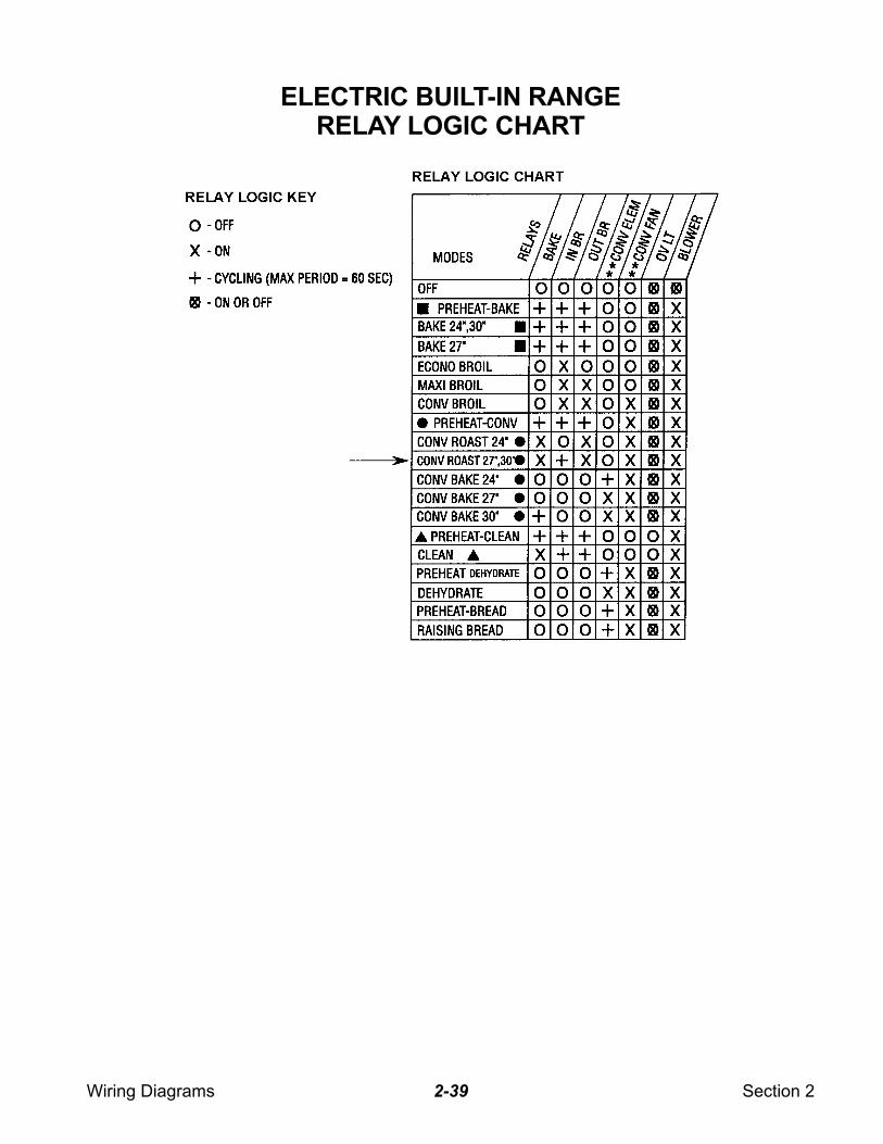
ELECTRIC BUILT-IN RANGERELAY LOGIC CHART
Wiring Diagrams Section 22-40
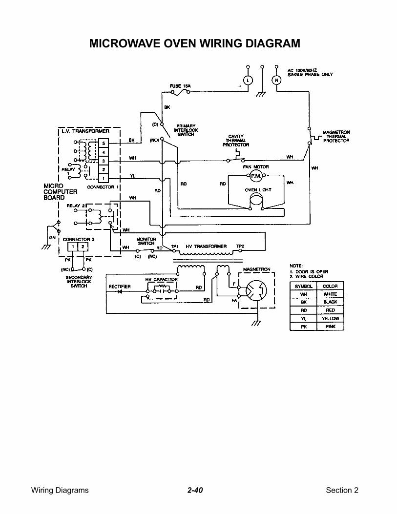
MICROWAVE OVEN WIRING DIAGRAM
Wiring Diagrams Section 22-41
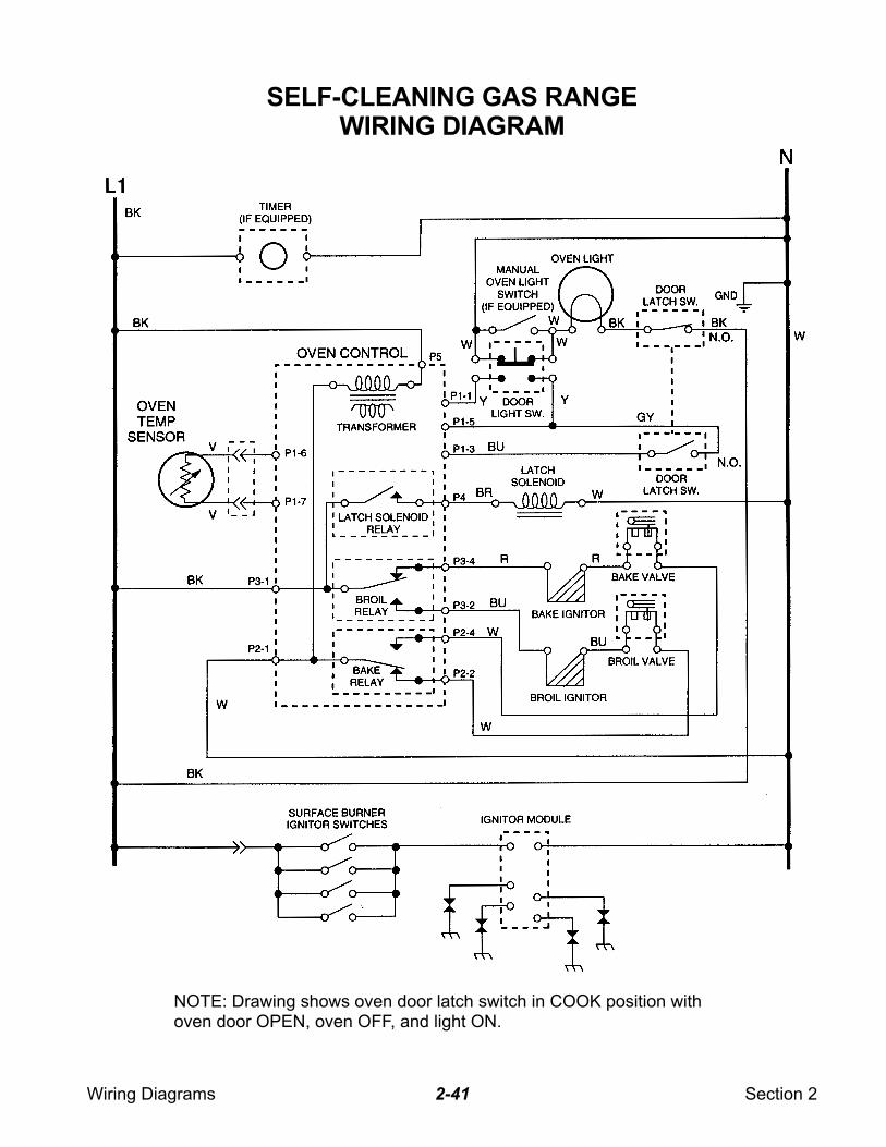
SELF-CLEANING GAS RANGEWIRING DIAGRAM
NOTE: Drawing shows oven door latch switch in COOK position withoven door OPEN, oven OFF, and light ON.
Wiring Diagrams Section 22-42
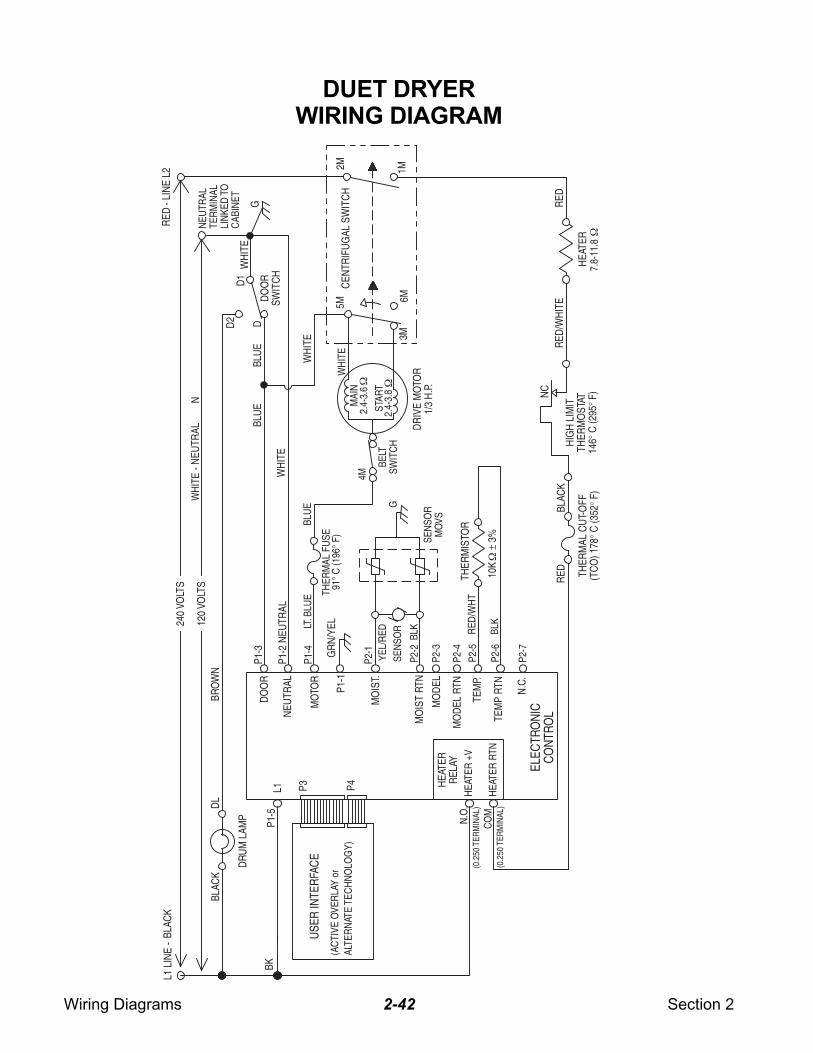
DUET DRYERWIRING DIAGRAM
120
VOLT
S
240
VOLT
SBL
ACK
L1 L
INE
-- L
INE
L2R
ED
WH
ITE
N
2M 1M
DO
OR
SWIT
CH
- NEU
TRAL
RED
/WH
ITE
D2
DR
IVE
MO
TOR
1/3
H.P
.
4MM
AIN
STAR
T
5M
6M
THER
MIS
TOR
BLAC
KD
L
HEA
TER
RED
BLAC
KC
ON
TRO
L
THER
MAL
CU
T-O
FF(T
CO
) 178
° C (3
52° F
)
NEU
TRAL
TER
MIN
ALLI
NKE
DTO
CAB
INET
CEN
TRIF
UG
AL S
WIT
CH
THER
MAL
FU
SE91
° C (1
96° F
)
HIG
H L
IMIT
THER
MO
STAT
146°
C (2
95° F
)
DO
OR
DRU
M L
AMP
MO
IST
RTN
MO
IST.
TEM
P.
SEN
SOR
NC
3M
D
D1
GBL
UE
BK
RED
BRO
WN
LT.B
LUE
BLU
E
BELT
SWIT
CH
WH
ITE
MO
DEL
RTN
L1
USE
R IN
TER
FAC
E
(AC
TIVE
OVE
RLA
Y or
ALTE
RN
ATE
TEC
HN
OLO
GY)
MO
TOR
HEA
TER
RTN
HEA
TER
+V
10K
±
3%
P3 P4
P1-3
P2-1
P2-2
P2-5
P2-4
P1-4
P1-5
HEA
TER
REL
AY
NEU
TRAL
P1-2
NEU
TRAL
MO
DEL
P2-3
N.O
.(0
.250
TER
MIN
AL)
CO
M(0
.250
TER
MIN
AL)
N.C
.
TEM
P RT
NP2
-6
P2-7
G
SEN
SOR
MO
VS
GR
N/Y
ELP1
-1
YEL/
RED BL
K RED
/WH
T
BLK
WH
ITE
WH
ITE
7.8-
11.8
BLU
E
WH
ITE
2.4-
3.8
2.4-
3.6
ELEC
TRO
NIC
Wiring Diagrams Section 22-43
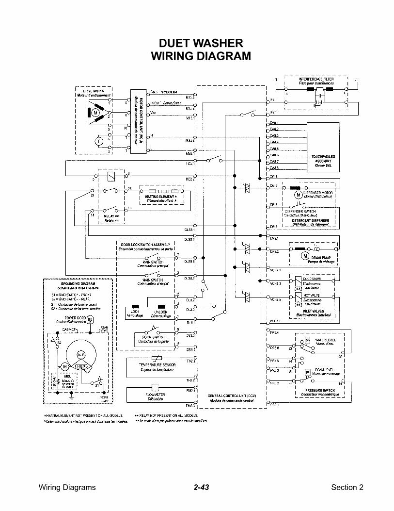
DUET WASHERWIRING DIAGRAM
Wiring Diagrams Section 22-44
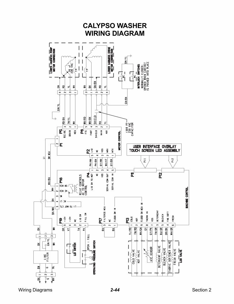
CALYPSO WASHERWIRING DIAGRAM
Wiring Diagrams Section 22-45
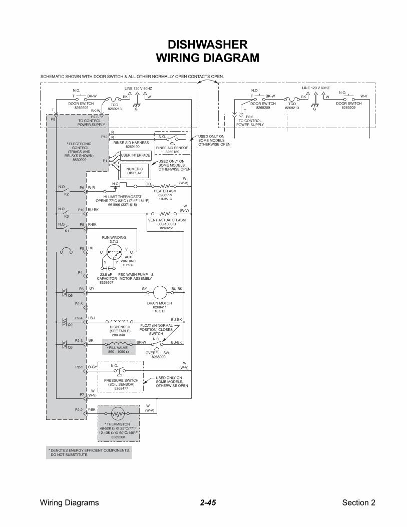
DISHWASHERWIRING DIAGRAM
DENOTES ENERGY EFFICIENT COMPONENTS.DO NOT SUBSTITUTE.
*
SCHEMATIC SHOWN WITH DOOR SWITCH & ALL OTHER NORMALLY OPEN CONTACTS OPEN.
DOOR SWITCH8269209
USER INTERFACE
VENT ACTUATOR ASM600-1800 Ω
8269251
HI-LIMIT THERMOSTATOPENS 77°C-83°C (171°F-181°F)
661566 (3371618)
PRESSURE SWITCH(SOIL SENSOR)
8268477
FILL VALVE890 - 1090 Ω OVERFILL SW.
8268909
THERMISTOR48-52K @ 25°C/77°F12-13K @ 60°C/140°F
8269208
ΩΩ
NUMERICDISPLAY
USED ONLY ONSOME MODELS,OTHERWISE OPEN
HEATER ASM826855910-35 Ω
DISPENSER(SEE TABLE)
280-340
USED ONLY ONSOME MODELS,OTHERWISE OPEN
RINSE AID SENSOR8269189
USED ONLY ONSOME MODELS,OTHERWISE OPEN
N.O.
N.O.
N.O.
N.O.
FLOAT (IN NORMALPOSITION) CLOSES
SWITCH
LINE 120 V 60HZ
BK W
GT
P6 W-R
P10 BU-BK
P9 R-BK
P3
BUP5
GY
P4
P2-4 LBU
P2-3 BR
P2-1 O-GY
P7
P8
K2
K3
K1
Q6
Q2
Q3
N.C. OR
BR-W
PSC WASH PUMP &MOTOR ASSEMBLY
P2-2 Y-BK
T
P2-5
BU-BK
BU-BK
ELECTRONICCONTROL
(TRIACS ANDRELAYS SHOWN)
8530909 P1
RR
N.O.
BU-BK
DRAIN MOTOR826841116.3 Ω
GY
BK-WT
TCO8269213
P12
23.5 uFCAPACITOR
8269507
P2-6
*
*
* RINSE AID HARNESS8269190
TO CONTROLPOWER SUPPLY
DOOR SWITCH8269209
W-V
DOOR SWITCH8269209
N.O.N.O.
LINE 120 V 60HZ
BK W
G
BK-WT
TCO8269213
T
P2-6
BK-W
TO CONTROLPOWER SUPPLY
RUN WINDING3.7 Ω
V
YY
AUXWINDING
6.25 Ω
(W-V)W
(W-V)W
(W-V)W
(W-V)W
(W-V)W
N.O.
N.O.

Wiring Diagrams Section 22-46
— NOTES —
PRODUCT SPECIFICATIONSAND
WARRANTY INFORMATION SOURCES
IN THE UNITED STATES:
FOR PRODUCT SPECIFICATIONS AND WARRANTY INFORMATION CALL:
FOR TECHNICAL ASSISTANCE WHILE AT THE CUSTOMER’S HOME CALL:
THE TECHNICAL ASSISTANCE LINE: 1-800-253-2870
HAVE YOUR STORE NUMBER READY TO IDENTIFY YOU AS ANAUTHORIZED SERVICER
FOR LITERATURE ORDERS:
PHONE: 1-800-851-4605
FOR TECHNICAL INFORMATION AND SERVICE POINTERS:
www.servicematters.com
IN CANADA:
FOR PRODUCT SPECIFICATIONS AND WARRANTY INFORMATION CALL:
1-800-461-5681
FOR TECHNICAL ASSISTANCE WHILE AT THE CUSTOMER’S HOME CALL:
THE TECHNICAL ASSISTANCE LINE: 1-800-488-4791
HAVE YOUR STORE NUMBER READY TO IDENTIFY YOU AS ANAUTHORIZED SERVICER
FOR WHIRLPOOL PRODUCTS: 1-800-253-1301FOR KITCHENAID PRODUCTS: 1-800-422-1230FOR ROPER PRODUCTS: 1-800-447-6737

CORPORATION


![6. Wiring Diagram - weidefamily.net coil Transmission control module ... WIRING DIAGRAM 6. Wiring Diagram. MEMO: 21 WIRING DIAGRAM ... 76 6-3 [D6R2] WIRING DIAGRAM 6.](https://static.fdocuments.net/doc/165x107/5aa0cc3b7f8b9a62178ea5e7/6-wiring-diagram-coil-transmission-control-module-wiring-diagram-6-wiring.jpg)