
ELECTRICAL TECHNOLOGY LAB - Dronacharya College of ... · to verify thevenin’s theorem 7-9 3. to...
46
ELECTRICAL TECHNOLOGY LAB (EE-103-F) LAB MANUAL (With V-Lab Links) I, II SEMESTER Department Of Electronics & Communication Engg. Dronacharya College Of Engineering Khentawas, Gurgaon – 123506
Transcript of ELECTRICAL TECHNOLOGY LAB - Dronacharya College of ... · to verify thevenin’s theorem 7-9 3. to...
ELECTRICAL TECHNOLOGY LAB (EE-103-F)
LAB MANUAL (With V-Lab Links)
I, II SEMESTER Department Of Electronics & Communication Engg.
Dronacharya College Of Engineering
Khentawas, Gurgaon – 123506
ELECTRICAL TECHNOLOGY (EE‐103‐F)
CONTENTS
Sr.No TITLE Page No. 1. TO VERIFY KVL AND KCL LAW 3-6
2. TO VERIFY THEVENIN’S THEOREM 7-9 3. TO VERIFY NORTAN’S THEOREM 10-12
4. TO VERIFY RECIPROCITY THEOREM 13-14 5. TO VERIFY MAXIMUM POWER TRANSFER THEOREM IN D.C 15-16
CIRCUIT 6. TO MEASURE THE POWER DRAWN BY A SINGLE PHASE AC 17-19
CKT USING THREE VOLTMETERS 7. TO PERFORM THE DIRECT LOAD TEST ON THE 20-22
TRANSFORMER AND PLOT THE CURVE BETWEEN EFFICIENCY AND VOLTAGE
8. TO STUDY FREQUENCY RESPONSE OF A SERIES R-L-C 23-25 CIRCUIT AND DETERMINE RESONANCE FREQUENCY
9. TO STUDY FREQUENCY RESPONSE OF PARALLEL R-L-C 26-28 CIRCUIT AND DETERMINE RESONANCE
10. TO STUDY VOLTMETER, AMMETER, WATTMETER & 29-31 MULTIMETER.
11. TO VERIFY MAXIMUM POWER TRANSFER THEOREM IN 32-33 A.C. CIRCUIT.
12. MEASUREMENT OF POWER IN A THREE PHASE SYSTEM BY 34-36 TWO WATTMETER METHOD
13 TO PERFORM DIRECT LOAD TEST OF A D.C.SHUNT 37-39 GENERATOR AND PLOT LOAD VOLTAGE V/S LOAD CURRENT
14 TO PERFORM THE OPEN CIRCUIT AND SHORT CIRCUIT 40-42 TEST ON THREE PHASE INDUCTION MOTOR
15 TO PLOT V CURVE OF SYNCHRONOUS MOTOR 43-46
LAB MANUAL(I,II SEM) Page 2
ELECTRICAL TECHNOLOGY (EE‐103‐F)
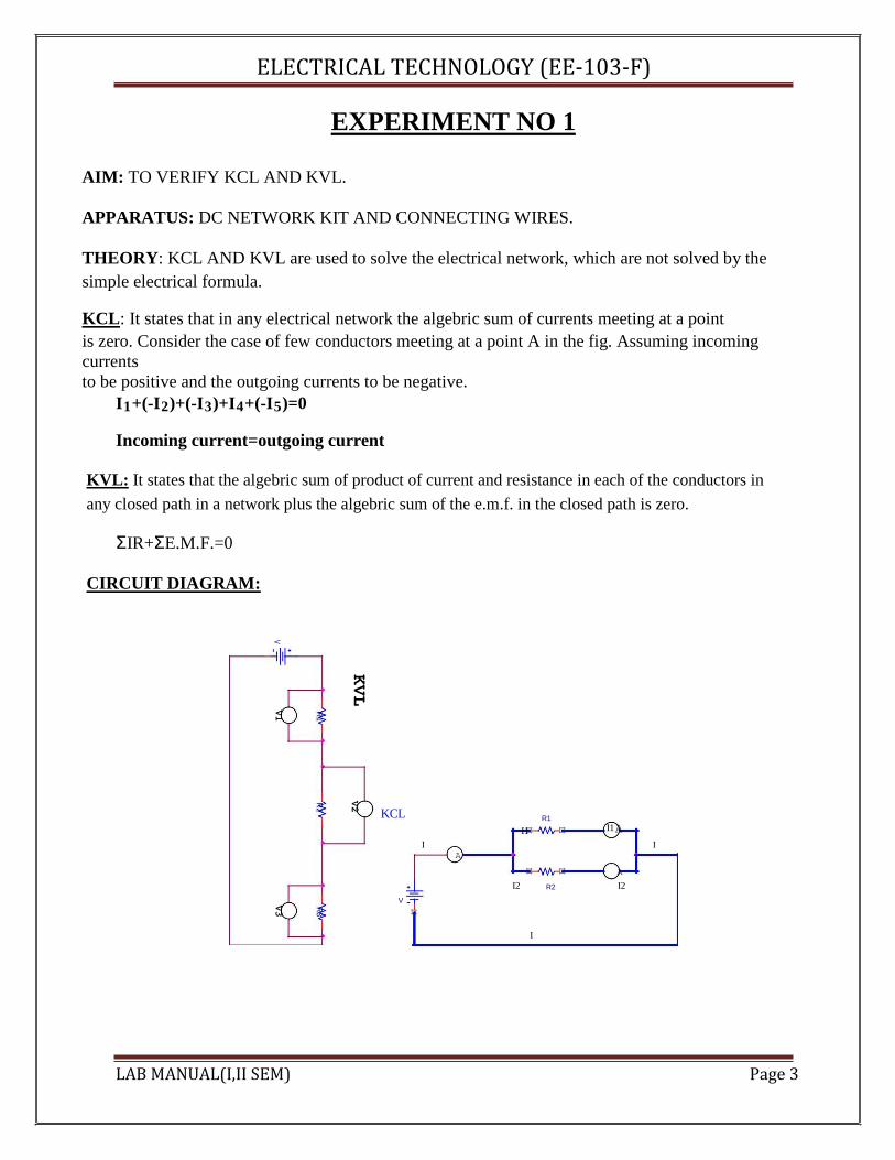
EXPERIMENT NO 1 AIM: TO VERIFY KCL AND KVL. APPARATUS: DC NETWORK KIT AND CONNECTING WIRES. THEORY: KCL AND KVL are used to solve the electrical network, which are not solved by the simple electrical formula. KCL: It states that in any electrical network the algebric sum of currents meeting at a point is zero. Consider the case of few conductors meeting at a point A in the fig. Assuming incoming currents to be positive and the outgoing currents to be negative.
I1+(-I2)+(-I3)+I4+(-I5)=0
Incoming current=outgoing current KVL: It states that the algebric sum of product of current and resistance in each of the conductors in any closed path in a network plus the algebric sum of the e.m.f. in the closed path is zero.
ΣIR+ΣE.M.F.=0
CIRCUIT DIAGRAM:
V
V1
R1
KVL
R2
V2 KCL
V3
R3
V
I1
R1 I1A
I A
I
A
I2 R2 I2
I
LAB MANUAL(I,II SEM) Page 3

ELECTRICAL TECHNOLOGY (EE‐103‐F)
PROCEDURE :
KCL: 1. Make the connection according to the ckt diagram 2. Set the three rheostats to their max value. 3. Switch on the power supply 4. Change the setting of the rheostats to get different readings in all the three ammeters. 5. Measure the current in the three ammeters 6. Check that at every time current in the main branch is equal to the sum of currents in the
two branches. repeat the setting of the rheostat 7. Switch off the power supply.
KVL: 1. Connect the circuit as per the circuit diagram 2. Switch on the power supply 3. Note down the readings of the voltmeters 4. Change the value of the rheostat and repeat the step several times and switch off the
power supply.
OBSERVATION TABLE:
KCL:
SR.NO. APPLIED I1 I2 I Il=I1+I2 REMARK VOLTAGE (mA) (mA) (mA) (mA) (volts)
KVL:
SR.NO. APPLIED V1 V2 V3 RESULT REMARK
VOLTAGE (volts) (volts) (volts) Vl=V1+V2+V3
(volts) (volts)
RESULT :
1The incoming current is found to be equal to the outgoing current

LAB MANUAL(I,II SEM) Page 4

ELECTRICAL TECHNOLOGY (EE‐103‐F)
2The total input voltage is equal to the total voltage drop in the ckt. DISCUSSION: KCL AND KVL are very important in solving the circuits where direct formula can’t be applied. PRECAUTIONS :
1. All connections should be tight and correct. 2. Switch off the supply when not in use. 3. Reading should be taken carefully.
QUESTIONS/ANSWERS: Q.1 What is the statement of Kirchhoff’s first law? A. The sum of the currents entering at any junction is equal to the sum of the currents
leaving the junction. Q.2 According to Kirchhoff’s second law, the algebraic sum of all IR drops and emf’s in any closed loop of a network is equal to… A. It is equal to zero. Q.3 Kirchoff’s second law is related to what? A. EMF and IR drops. Q.4 What is the internal resistance of the ideal voltage source? A. Zero Q.5 What is higher , the terminal voltage or the emf? A. The emf Q.6 What is he internal resistance of the current source ideally? A. Infinity Q.7 What is the active network? A. An active network is that which contains one or more than one sources of emf. or current sources Q.8 What is the bilateral network? A. It is the circuit whose properties are same in either direction Q.9 What is the difference between a node and a branch? A. A node is a junction in the circuit where two or more than two circuit elements are connected together. The part of the network, which lies between two junctions, is called branch. Q.10 What is the non-linear circuit? A. The circuit whose parameters change with the change in voltage and current is called the non-linear ckt. V-Lab Link:- http://amrita.vlab.co.in/?sub=1&brch=75&sim=217&cnt=1 LAB MANUAL(I,II SEM) Page 5
ELECTRICAL TECHNOLOGY (EE‐103‐F)
EXPERIMENT NO. 2
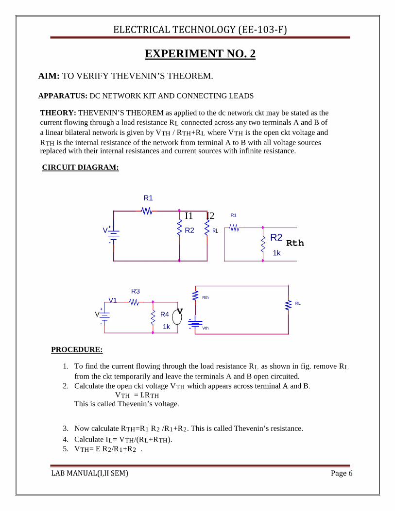
AIM: TO VERIFY THEVENIN’S THEOREM. APPARATUS: DC NETWORK KIT AND CONNECTING LEADS THEORY: THEVENIN’S THEOREM as applied to the dc network ckt may be stated as the current flowing through a load resistance RL connected across any two terminals A and B of a linear bilateral network is given by VTH / RTH+RL where VTH is the open ckt voltage and RTH is the internal resistance of the network from terminal A to B with all voltage sources replaced with their internal resistances and current sources with infinite resistance.
CIRCUIT DIAGRAM:
R1
I1 I2 R1
V R2 RL R2
Rth 1k
R3
V1 Rth
RL
V R4 V
1k Vth
PROCEDURE:
1. To find the current flowing through the load resistance RL as shown in fig. remove RL from the ckt temporarily and leave the terminals A and B open circuited.
2. Calculate the open ckt voltage VTH which appears across terminal A and B. VTH = I.RTH
This is called Thevenin’s voltage.
3. Now calculate RTH=R1 R2 /R1+R2. This is called Thevenin’s resistance. 4. Calculate IL= VTH/(RL+RTH). 5. VTH= E R2/R1+R2 .
LAB MANUAL(I,II SEM) Page 6

ELECTRICAL TECHNOLOGY (EE‐103‐F)
OBSERVATION TABLE:
SR.NO APPLIED VTH VTH RTH IL IL RESULT VOLTAGE (volts) (volts) (Ohms) (mA) (mA) (volts) Theo. Pract. Pract. Theo.
RESULT: THEVENIN’S THEOREM has been verified. DISCUSSION: In Thevinin’s equivalent circuit Thevenin’s equivalent voltage is in series with Thevenin’s resistance and the load resistance. PRECAUTIONS:
1. Switch off the supply when not in use. 2. Reading should be taken carefully. 3. All connections should be tight and correct.
QUESTIONS/ANSWERS Q.1 To what type of circuit Thevenin’s theorem is applicable A. Linear and bilateral Q.2 What is the use of Thevenin’s theorem? A. To convert the complex ckt into a voltage source and a series resistance Q.3 How RTH is connected with the ckt? A. In series Q.4 How is RTH connected with the load resistance? A. In series Q.5 What modification is done in galvanometer to convert it into a ammeter? A. A large resistance in parallel Q.6 What modification is done in the galvanometer to convert it into a voltmeter? A. A series resistance Q.7 Resistance is a n active element or the passive? A. Passive
LAB MANUAL(I,II SEM) Page 7
ELECTRICAL TECHNOLOGY (EE‐103‐F)
Q.8 How will you calculate the RTH? A. The resistance between the two terminals Q.9 In place of current source, what is placed while calculating RTH? A. Replace current source by open ckt Q.10 In place of voltage source which electrical parameters is placed? A. A short ckt. V-Lab Link:- http://amrita.vlab.co.in/?sub=1&brch=75&sim=313&cnt=1 LAB MANUAL(I,II SEM) Page 8
ELECTRICAL TECHNOLOGY (EE‐103‐F)
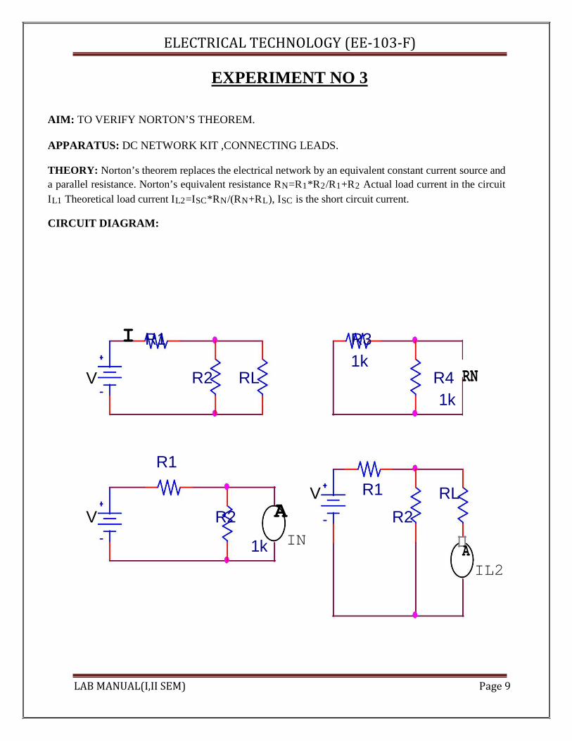
EXPERIMENT NO 3 AIM: TO VERIFY NORTON’S THEOREM. APPARATUS: DC NETWORK KIT ,CONNECTING LEADS. THEORY: Norton’s theorem replaces the electrical network by an equivalent constant current source and a parallel resistance. Norton’s equivalent resistance RN=R1*R2/R1+R2 Actual load current in the circuit IL1 Theoretical load current IL2=ISC*RN/(RN+RL), ISC is the short circuit current. CIRCUIT DIAGRAM:
I R1 R3
R2 RL
1k
R4 RN
V
1k
R1
V R1 RL
V R2 A R2
IN
1k A
IL2
LAB MANUAL(I,II SEM) Page 9
ELECTRICAL TECHNOLOGY (EE‐103‐F) OBSERVATION TABLE:
SR.NO. APPLIED IN RN IL1 IL2 ERROR RESULT
VOLTAGE (mA) (Ω) (mA) (mA) IL1 - IL2 (volts)
PROCEDURE :
1. Connect the ckt as per the ckt diagram 2. Remove the load resistance 3. Find the Norton’s resistance RN 4. Measure the Norton’s current IN 5. Now measure the current in the load resistance directly 6. Find out the current in the load 7. Using formula find out the current in the load resistance 8. Verify that these two are equal.
RESULT : Norton’s theorem is verified
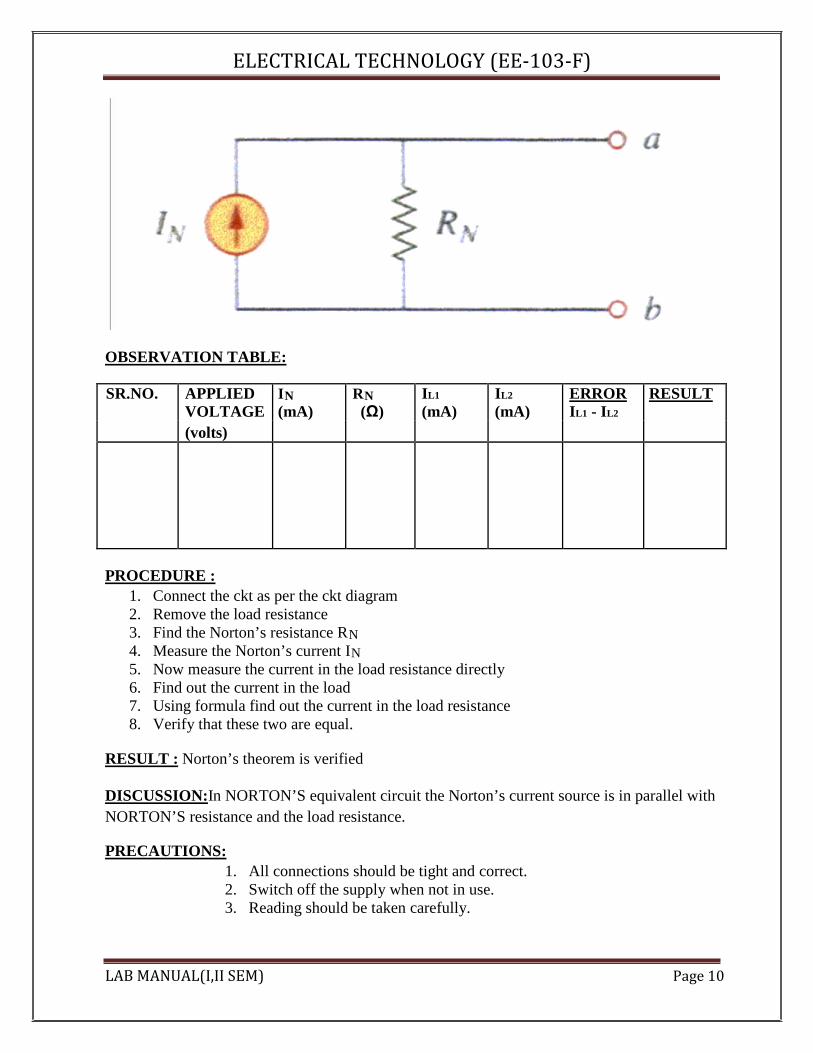
DISCUSSION:In NORTON’S equivalent circuit the Norton’s current source is in parallel with NORTON’S resistance and the load resistance.
PRECAUTIONS:
1. All connections should be tight and correct. 2. Switch off the supply when not in use. 3. Reading should be taken carefully.
LAB MANUAL(I,II SEM) Page 10

ELECTRICAL TECHNOLOGY (EE‐103‐F) QUESTIONS/ANSWERS: Q.1 To what type of network Norton’s theorem applicable? A. Two terminal linear network containing independent voltage and current sources. Q.2 How is RN connected to IN? A. In the parallel
Q.3 What is placed in place of voltage sources while calculating the RN? A. Their internal resistance replaces these.
Q.4 Give an example of unilateral ckt? A. Diode rectifier Q.5 What is unilateral ckt? A. Whose characteristics changes with the change in direction of operation Q.6 Give one example of the bilateral n/w? A. Transmission lines Q.7 What is the limitation of Ohm’s law? A. Provided physical conditions do not change Q.8 What is the reason that ground pin are made of greater diameter in the plugs? A. R=ρL/A Q.9 Where is the voltage divider rule applicable? A. Two resistance in series Q.10 Where is the current divider rule applicable? A. When there are two resistances in parallel. V-lab Link:- http://amrita.vlab.co.in/index.php?sub=1&brch=75&sim=312&cnt=1
LAB MANUAL(I,II SEM) Page 11
ELECTRICAL TECHNOLOGY (EE‐103‐F)
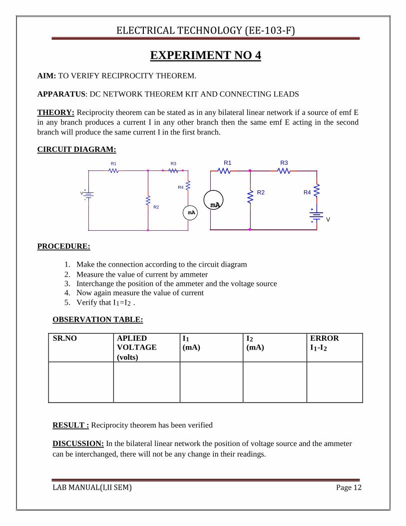
EXPERIMENT NO 4 AIM: TO VERIFY RECIPROCITY THEOREM. APPARATUS: DC NETWORK THEOREM KIT AND CONNECTING LEADS THEORY: Reciprocity theorem can be stated as in any bilateral linear network if a source of emf E in any branch produces a current I in any other branch then the same emf E acting in the second branch will produce the same current I in the first branch. CIRCUIT DIAGRAM:
R1 R3 R1 R3
R4 R4
V R2
R2 mA
mA V
PROCEDURE:
1. Make the connection according to the circuit diagram 2. Measure the value of current by ammeter 3. Interchange the position of the ammeter and the voltage source 4. Now again measure the value of current 5. Verify that I1=I2 .
OBSERVATION TABLE:
SR.NO APLIED I1 I2 ERROR
VOLTAGE (mA) (mA) I1-I2 (volts)
RESULT : Reciprocity theorem has been verified
DISCUSSION: In the bilateral linear network the position of voltage source and the ammeter can be interchanged, there will not be any change in their readings.
LAB MANUAL(I,II SEM) Page 12

ELECTRICAL TECHNOLOGY (EE‐103‐F)
PRECAUTIONS:
1.Switch off the supply when not in use. 2.Reading should be taken carefully. 3.All connections should be tight and correct.
QUESTIONS/ANSWERS: Q.1To what type of the ckt, the reciprocity theorem applicable? A. Linear and bilateral Q.2 What is transfer resistance in reciprocity theorem? A. E/I= transfer resistance Q.3 Is reciprocity theorem applicable to ac? A. Yes Q.4 What are mutually transferable in the reciprocity theorem? A. E and I are mutually transferable Q.5 Is this theorem applicable to the ckt having capacitor or inductor? A. No, it is applicable to only resistive ac ckt. Q.6 What is the frequency of mains? A. 50 hz Q.8 What is the reference node in the ckt? A. The reference node is the node with respect to which the potential at different points are calculated. Q.9 What is conventional current? A.The current flowing from the positive to negative terminal of the battery is called the conventional current. Q.10 What is MCB? A. Miniature ckt breaker LAB MANUAL(I,II SEM) Page 13
ELECTRICAL TECHNOLOGY (EE‐103‐F)
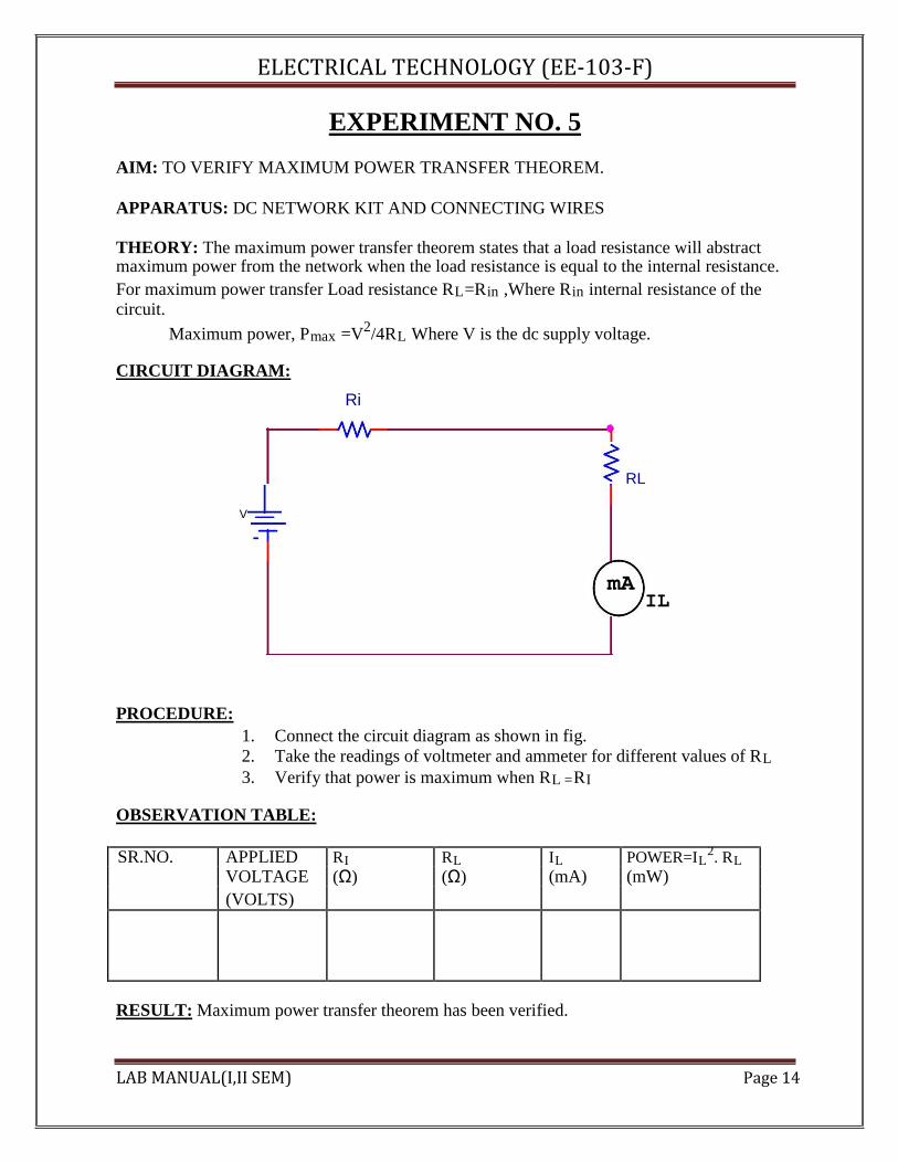
EXPERIMENT NO. 5 AIM: TO VERIFY MAXIMUM POWER TRANSFER THEOREM. APPARATUS: DC NETWORK KIT AND CONNECTING WIRES THEORY: The maximum power transfer theorem states that a load resistance will abstract maximum power from the network when the load resistance is equal to the internal resistance. For maximum power transfer Load resistance RL=Rin ,Where Rin internal resistance of the circuit.
Maximum power, Pmax =V2/4RL Where V is the dc supply voltage. CIRCUIT DIAGRAM:
Ri
V
RL
mA PROCEDURE:
IL
1. Connect the circuit diagram as shown in fig. 2. Take the readings of voltmeter and ammeter for different values of RL 3. Verify that power is maximum when RL =RI
OBSERVATION TABLE:
SR.NO. APPLIED RI RL IL POWER=IL2. RL
VOLTAGE (Ω) (Ω) (mA) (mW) (VOLTS)
RESULT: Maximum power transfer theorem has been verified.
LAB MANUAL(I,II SEM) Page 14

ELECTRICAL TECHNOLOGY (EE‐103‐F)
DISCUSSION: In the network maximum power is transferred when the load resistance is equal to the internal resistance of the network. PRECAUTIONS:
1.Switch off the supply when not in use. 2.Reading should be taken carefully. 3.All connections should be tight and correct.
QUESTIONS/ANSWERS: Q.1 What is load matching? A. The process of adjusting the load resistance for maximum power transfer is called load matching Q.2 What is max power transfer formula?
A. Pmax=Eth2/4RL Q.3 What is the field of application of this theorem? A. Motorcars ,Telephone lines and TV aerial leads Q.4 What is electric network? A. An electric ckt arises when a no. of parameters or electric elements coexist or combine in a certain arrangement. Q.5 What is necessary to know the polarity of voltage drop across a resistance? A. Direction of current through the resistance. Q.6 What is the reason that terminal voltage is less than emf? A. Because there is some drop across the internal resistance. Q.7 What is the resistance of ideal voltage source? A. Zero Q.8 When will the power extracted from a ckt is maximum? A. When RL is equal to the internal resistance of the ckt. Q.9 How is the ammeter connected in circuit? A. In series Q.10 To find the voltage drop across a resistance, where should the voltmeter be connected? A. In parallel. LAB MANUAL(I,II SEM) Page 15
ELECTRICAL TECHNOLOGY (EE‐103‐F)
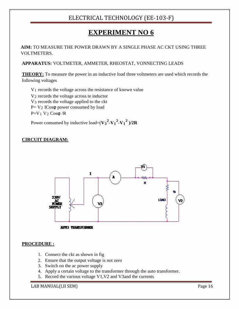
EXPERIMENT NO 6 AIM: TO MEASURE THE POWER DRAWN BY A SINGLE PHASE AC CKT USING THREE VOLTMETERS. APPARATUS: VOLTMETER, AMMETER, RHEOSTAT, VONNECTING LEADS
THEORY: To measure the power in an inductive load three voltmeters are used which records the following voltages
V1 records the voltage across the resistance of known value V2 records the voltage across te inductor V3 records the voltage applied to the ckt P= V2 ICosφ power consumed by load P=V1 V2 Cosφ /R
Power consumed by inductive load=(V3
2-V12-V1
2 )/2R
CIRCUIT DIAGRAM:
PROCEDURE :
1. Connect the ckt as shown in fig 2. Ensure that the output voltage is not zero 3. Switch on the ac power supply 4. Apply a certain voltage to the transformer through the auto transformer. 5. Record the various voltage V1,V2 and V3and the currents
LAB MANUAL(I,II SEM) Page 16

ELECTRICAL TECHNOLOGY (EE‐103‐F)
6. Repeat the whole experiment for the different values of the voltage 7. Find the value of V/I in all the cases 8. Switch off the power supply after use.
OBSERVATION TABLE:
S.NO. V1 (VOLTS) V2 (VOLTS) V3 (VOLTS) I(mA) P=(V3
2-V12-V1
2 )/2R (mW)
RESULT : The power drawn by single phase ac ckt using three voltmeter is…………..
DISCUSSION: The power consumed by the single phase ac ckt can be calculated by the readings of three voltmeters.
PRECAUTIONS:
1. All connections should be tight and correct. 2. Switch off the supply when not in use. 3. Reading should be taken carefully.
QUESTIONS/ANSWERS:
Q.1 What is faradays first law? A. When magnetic flux linked with a ckt changes, an emf is induced.
Q.2 What is faraday’s second law? A.The magnitude of the induced EMF is equal to the rate of change of flux linkage
Q.3 What is the dimension of √LC? A. It has the unit of velocity
Q.4 What is the power drawn by a three phase balanced load? A.√3 VL IL cosø
Q.5 Can a repulsion-induction motor ever run at super synchronous speed? A.YES
LAB MANUAL(I,II SEM) Page 17

ELECTRICAL TECHNOLOGY (EE‐103‐F) Q.6 Can a dc shunt motor run at heavy loads? A. At heavy loads the internal drop becomes very large and hence the terminal voltage are reduced to a very low value and finally resulting into run away. Q.7 What is ACB? A.Air ckt breaker Q.8 Which electric motor is used in ceiling fan? A. Single phase capacitor run induction motor Q.9 Which motor is use in the refrigerator? A. Single phase capacitor start induction motor Q.10 In which units transformers are rated? A. KVA LAB MANUAL(I,II SEM) Page 18
ELECTRICAL TECHNOLOGY (EE‐103‐F)
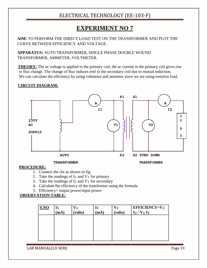
EXPERIMENT NO 7 AIM: TO PERFORM THE DIRECT LOAD TEST ON THE TRANSFORMER AND PLOT THE CURVE BETWEEN EFFICIENCY AND VOLTAGE. APPARATUS: AUTO TRANSFORMER, SINGLE PHASE DOUBLE WOUND TRANSFORMER, AMMETER, VOLTMETER. THEORY: The ac voltage is applied to the primary coil, the ac current in the primary coil gives rise to flux change. The change of flux induces emf in the secondary coil due to mutual induction. We can calculate the efficiency by using voltmeter and ammeter since we are using resistive load.
CIRCUIT DIAGRAM:
P1 S1
A A
I1 I2
L
230V V1 V2
O
AC A
SUPPLY
D
AUTO P2 S2 STEP DOWN
TRANSFORMER TRANSFORMER PROCEDURE:
1. Connect the ckt as shown in fig. 2. Take the readings of I1 and V1 for primary 3. Take the readings of I2 and V2 for secondary 4. Calculate the efficiency of the transformer using the formula 5. Efficiency= output power/input power.
OBSERVATION TABLE:
S.NO I1 V1 I2 V2 EFFICIENCY=V2 (mA) (volts) (mA) (volts) I2 / V1 I1
LAB MANUAL(I,II SEM) Page 19
ELECTRICAL TECHNOLOGY (EE‐103‐F)
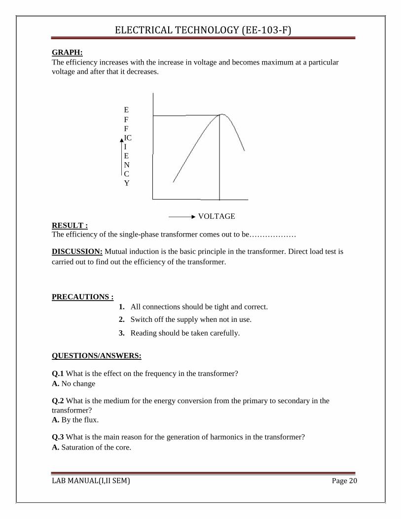
GRAPH: The efficiency increases with the increase in voltage and becomes maximum at a particular voltage and after that it decreases.
E F F IC I E N C Y
VOLTAGE RESULT : The efficiency of the single-phase transformer comes out to be……………… DISCUSSION: Mutual induction is the basic principle in the transformer. Direct load test is carried out to find out the efficiency of the transformer. PRECAUTIONS :
1. All connections should be tight and correct. 2. Switch off the supply when not in use.
3. Reading should be taken carefully.
QUESTIONS/ANSWERS: Q.1 What is the effect on the frequency in the transformer? A. No change Q.2 What is the medium for the energy conversion from the primary to secondary in the transformer? A. By the flux. Q.3 What is the main reason for the generation of harmonics in the transformer? A. Saturation of the core. LAB MANUAL(I,II SEM) Page 20

ELECTRICAL TECHNOLOGY (EE‐103‐F)
Q.4 Why are the ferrite cores used in the high frequency transformer? A. High resistance Q.5 What type of winding is used in the 3-phase shell type transformer? A. Sandwich type Q.6 What is increased in step up transformer? A. Voltage
Q.7 What is the effect on voltage in step down transformer? A. Voltage is decreased Q.8 What is the formula of efficiency? A. Output energy/input energy Q.9 What is the function of bushings in the transformer? A. To make the external connections Q 10 What is the principal of transformer? A. Mutual induction. LAB MANUAL(I,II SEM) Page 21

ELECTRICAL TECHNOLOGY (EE‐103‐F)
EXPERIMENT NO 8 AIM: TO STUDY FREQUENCY RESPONSE OF SERIES R-L-C CIRCUIT AND DETERMINE RESONANCE FREQUENCY. APPARATUS: CRO, AUDIO FREQUENCY GENERATOR,MULTIMETER AND CONNECTING LEADS. THEORY: In the series resonance circuit , the net reactance
X=XL-XC So impedence of the ckt is
Z=√(R2+ (XL-XC )2) at the resonance frequency the capacitive reactance becomes equal to the inductive reactance.
XL =XC w0L=1/w0
C f0=1/2π√LC
CIRCUIT DIAGRAM: 50uH
L
C
INPUT I1
AUDIO 680 R OUTPUT
FREQUENCY
Ohm
PROCEDURE :
1. Make the connection s shown in fig. 2. Frequency is given by audio frequency generator. 3. Change the frequency and note the reading carefully. 4. At certain frequency the voltage becomes maximum after which the voltage decreases.
This is the resonance frequency. 5. Plot a graph between frequency and voltage.
LAB MANUAL(I,II SEM) Page 22
ELECTRICAL TECHNOLOGY (EE‐103‐F)
OBSERVATION TABLE:
S.NO FREQUENCY (KHz) VOLTAGE (volts)
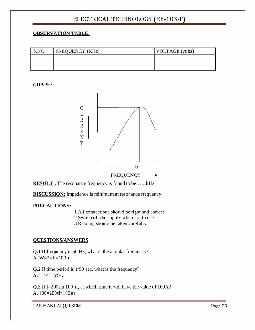
GRAPH:
C U R R E N T
fr
FREQUENCY RESULT : The resonance frequency is found to be……kHz.
DISCUSSION: Impedance is minimum at resonance frequency.
PRECAUTIONS:
1 All connections should be tight and correct. 2 Switch off the supply when not in use. 3 Reading should be taken carefully.
QUESTIONS/ANSWERS Q.1 If frequency is 50 Hz, what is the angular frequency? A. W=2πf =100π
Q.2 If time period is 1/50 sec, what is the frequency? A. f=1/T=50Hz
Q.3 If I=200sin 100πt, at which time it will have the value of 100A? A. 100=200sin100πt
LAB MANUAL(I,II SEM) Page 23

ELECTRICAL TECHNOLOGY (EE‐103‐F)
1/2=sin 100πt 100πt=π/6 t=1/600sec
Q.4 What is the average value of a square wave of peak value 200V? A. 200V Q.5 What is the relation between the max value and the average value of the square wave? A. Both are same Q.6 What is the form factor? A. RMS/average Q.7 What is the form factor for a sine wave? A. 1.11 Q.8 What is the impedance for a series resonance circuit? A. R Q.9 What is the condition for resonance in a series RLC ckt? A. XL=XC Q.10 What is the quality factor? A. Quality factor = fr/B.W.
V-lab link: http://amrita.vlab.co.in/?sub=1&brch=75&sim=330&cnt=1 LAB MANUAL(I,II SEM) Page 24
ELECTRICAL TECHNOLOGY (EE‐103‐F)
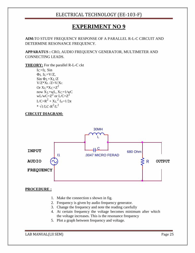
EXPERIMENT NO 9 AIM:TO STUDY FREQUENCY RESPONSE OF A PARALLEL R-L-C CIRCUIT AND DETERMINE RESONANCE FREQUENCY. APPARATUS : CRO, AUDIO FREQUENCY GENERATOR, MULTIMETER AND CONNECTING LEADS. THEORY: For the parallel R-L-C ckt
IC=IL Sin ΦL IL=V/Z, Sin ΦL=XL/Z V/Z*XL /Z=V/XC Or XL*XC=Z2 now XL=wL, XC=1/wC wL/wC=Z2 or L/C=Z2 L/C=R2 + XL
2 fo=1/2π * √1/LC-R2/L2
CIRCUIT DIAGRAM:
30MH
L
INPUT C
I1 680 Ohm
AUDIO
.0047 MICRO FERAD
R OUTPUT
FREQUENCY
PROCEDURE :
1. Make the connection s shown in fig. 2. Frequency is given by audio frequency generator. 3. Change the frequency and note the reading carefully 4. At certain frequency the voltage becomes minimum after which
the voltage increases. This is the resonance frequency 5. Plot a graph between frequency and voltage.
LAB MANUAL(I,II SEM) Page 25
ELECTRICAL TECHNOLOGY (EE‐103‐F) OBSERVATION TABLE:
SR.NO FREQUENCY (KHz) VOLTAGE (volts)
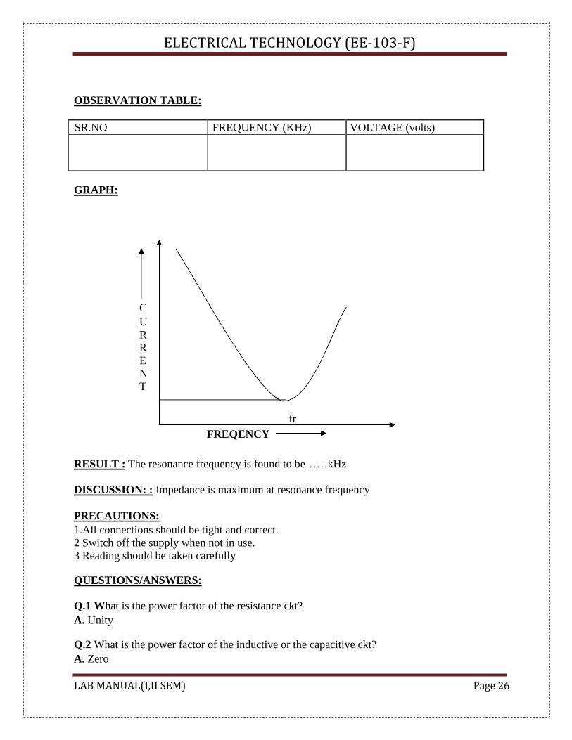
GRAPH:
C U R R E N T
fr FREQENCY
RESULT : The resonance frequency is found to be……kHz.
DISCUSSION: : Impedance is maximum at resonance frequency
PRECAUTIONS: 1.All connections should be tight and correct. 2 Switch off the supply when not in use. 3 Reading should be taken carefully
QUESTIONS/ANSWERS:
Q.1 What is the power factor of the resistance ckt? A. Unity
Q.2 What is the power factor of the inductive or the capacitive ckt? A. Zero
LAB MANUAL(I,II SEM) Page 26

ELECTRICAL TECHNOLOGY (EE‐103‐F) Q.3 What is the effect of the inductance on the time constant in any inductive ckt? A. Increases with increase in inductance and decreases with decrease in R Q.4 What is the effect of dc flow on the dc? A. Only at the time of on and off Q.5 Can all the laws of the dc be applied to the ac ckt having resistance? A. Yes Q.6 What is the time constant of the capacitive ckt? A. RC Q.7 What is the effect of length of iron path on inductance? A. Inductance varies inversely as the length of iron path. Q.8 If two signals having same frequency have opposite phase, what is the phase angle between them?
A. 1800 Q.9 For least power consumption what should be the phase angle between current and voltage?
A. 900 Q.10 What is magnified by the parallel RLC ckt? A. current. V-Lab Link: http://amrita.vlab.co.in/index.php?sub=1&brch=75&sim=325&cnt=1 LAB MANUAL(I,II SEM) Page 27
ELECTRICAL TECHNOLOGY (EE‐103‐F)
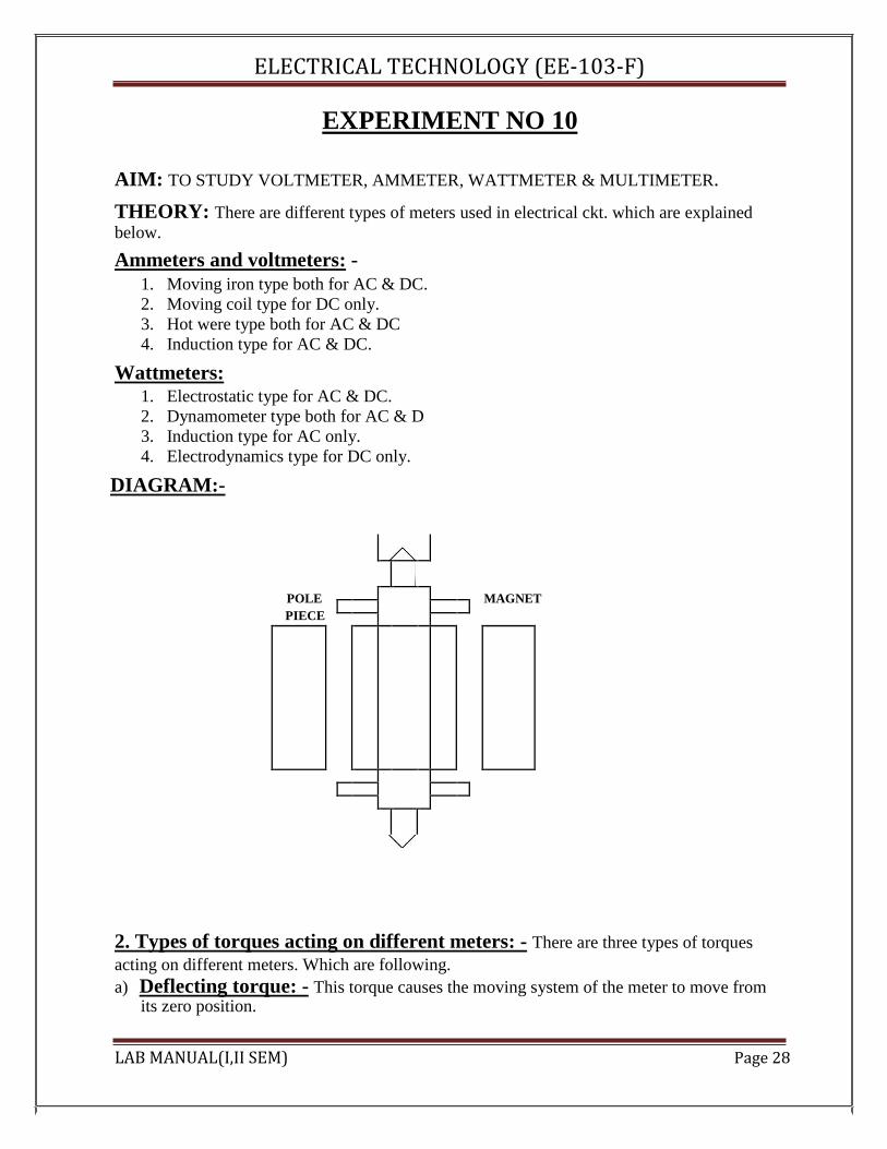
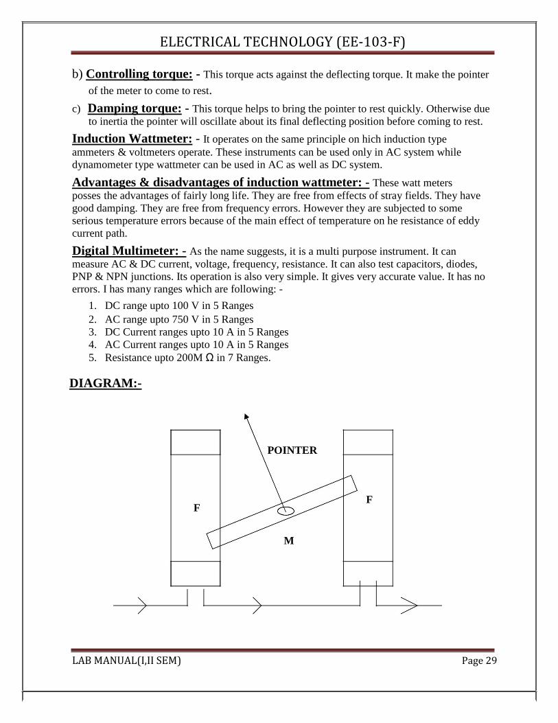
EXPERIMENT NO 10 AIM: TO STUDY VOLTMETER, AMMETER, WATTMETER & MULTIMETER.
THEORY: There are different types of meters used in electrical ckt. which are explained below. Ammeters and voltmeters: -
1. Moving iron type both for AC & DC. 2. Moving coil type for DC only. 3. Hot were type both for AC & DC 4. Induction type for AC & DC.
Wattmeters:
1. Electrostatic type for AC & DC. 2. Dynamometer type both for AC & D 3. Induction type for AC only. 4. Electrodynamics type for DC only.
DIAGRAM:-
POLE
MAGNET
PIECE
2. Types of torques acting on different meters: - There are three types of torques acting on different meters. Which are following. a) Deflecting torque: - This torque causes the moving system of the meter to move from
its zero position. LAB MANUAL(I,II SEM) Page 28
ELECTRICAL TECHNOLOGY (EE‐103‐F)
b) Controlling torque: - This torque acts against the deflecting torque. It make the pointer
of the meter to come to rest. c) Damping torque: - This torque helps to bring the pointer to rest quickly. Otherwise due
to inertia the pointer will oscillate about its final deflecting position before coming to rest. Induction Wattmeter: - It operates on the same principle on hich induction type ammeters & voltmeters operate. These instruments can be used only in AC system while dynamometer type wattmeter can be used in AC as well as DC system. Advantages & disadvantages of induction wattmeter: - These watt meters posses the advantages of fairly long life. They are free from effects of stray fields. They have good damping. They are free from frequency errors. However they are subjected to some serious temperature errors because of the main effect of temperature on he resistance of eddy current path. Digital Multimeter: - As the name suggests, it is a multi purpose instrument. It can measure AC & DC current, voltage, frequency, resistance. It can also test capacitors, diodes, PNP & NPN junctions. Its operation is also very simple. It gives very accurate value. It has no errors. I has many ranges which are following: -
1. DC range upto 100 V in 5 Ranges 2. AC range upto 750 V in 5 Ranges 3. DC Current ranges upto 10 A in 5 Ranges 4. AC Current ranges upto 10 A in 5 Ranges 5. Resistance upto 200M Ω in 7 Ranges.
DIAGRAM:-
POINTER
F
F
M LAB MANUAL(I,II SEM) Page 29

ELECTRICAL TECHNOLOGY (EE‐103‐F)
RESULT: The different measuring instruments have been studied.
DISCUSSION: Ammeters are used to measure the current but the moving coil type ammeter is used only for AC. Induction type wattmeter is used to measure the AC only, while the electrodynamics type wattmeter is used for DC only.
PRECAUTIONS:
1 All connections should be tight and correct. 2 Switch off the supply when not in use. 3 Reading should be taken carefully.
QUESTIONS /ANSWERS:
Q.1 What is the cheaper method of starting a 3-phase induction moor? A. Direct over load starting
Q.2 When a dc motor produces a max output power? A. When back emf is equal to half of the applied voltage.
Q.3 What is the use of wattmeter? A. it is used to measure the power consumed in a ckt.
Q.4 What are the different types of the wattmeter? A. Dynamometer, induction and electrostatic
Q.5 What is the use of integrating or the energy meter? A. it is used to measure the quantity of electric energy supplied to the ckt in a given time.
Q.6 What is a meggar? A. These are the instruments which are used to measure the insulation resistance relative to earth.
Q.7 What are the two types of the moving iron instruments? A. Attraction type ,Repulsion type
Q.8 What are the different types of the moving coil instruments? A. Permanent magnet type ,Dynamometer type
Q.9 What are the sources of error with the dc in moving iron instruments? A. Error due to hysteresis, Error due to stray field
Q.10 What are the errors with the ac in moving coil instruments? A. Error due to hysteresis, Error due to stray field
LAB MANUAL(I,II SEM) Page 30
ELECTRICAL TECHNOLOGY (EE‐103‐F)
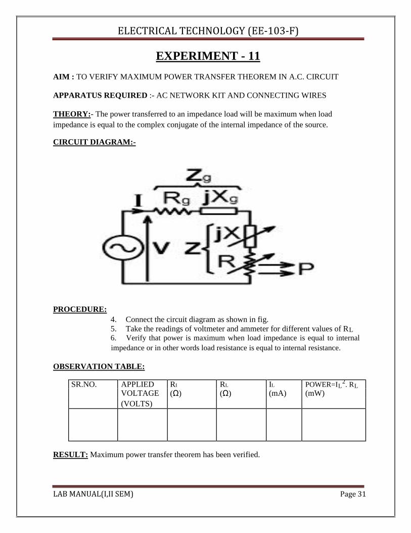
EXPERIMENT - 11 AIM : TO VERIFY MAXIMUM POWER TRANSFER THEOREM IN A.C. CIRCUIT APPARATUS REQUIRED :- AC NETWORK KIT AND CONNECTING WIRES THEORY:- The power transferred to an impedance load will be maximum when load impedance is equal to the complex conjugate of the internal impedance of the source. CIRCUIT DIAGRAM:- PROCEDURE:
4. Connect the circuit diagram as shown in fig. 5. Take the readings of voltmeter and ammeter for different values of RL 6. Verify that power is maximum when load impedance is equal to internal impedance or in other words load resistance is equal to internal resistance.
OBSERVATION TABLE: SR.NO. APPLIED RI RL IL POWER=IL
2. RL VOLTAGE (Ω) (Ω) (mA) (mW) (VOLTS)
RESULT: Maximum power transfer theorem has been verified. LAB MANUAL(I,II SEM) Page 31

ELECTRICAL TECHNOLOGY (EE‐103‐F)
DISCUSSION: In the network maximum power is transferred when the load resistance is equal to the internal resistance of the network. PRECAUTIONS:
1.Switch off the supply when not in use. 2.Reading should be taken carefully. 3.All connections should be tight and correct.
QUESTIONS/ANSWERS: Q.1 What is load matching? A. The process of adjusting the load resistance for maximum power transfer is called load matching Q.2 What is max power transfer formula?
A. P max = V2/4RL Q.3 What is the field of application of this theorem? A. Motorcars ,Telephone lines and TV aerial leads Q.4 What is electric network? A. An electric ckt arises when a no. of parameters or electric elements coexist or combine in a certain arrangement. Q.5 What is necessary to know the polarity of voltage drop across a resistance? A. Direction of current through the resistance. Q.6 What is the reason that terminal voltage is less than emf? A. Because there is some drop across the internal resistance. Q.7 What is the resistance of ideal voltage source? A. Zero Q.8 When will the power extracted from a ckt is maximum? A. When load impedance is equal to internal impedance. Q.9 How is the ammeter connected in circuit? A. In series Q.10 To find the voltage drop across a resistance, where should the voltmeter be connected? A. In parallel. LAB MANUAL(I,II SEM) Page 32
ELECTRICAL TECHNOLOGY (EE‐103‐F)
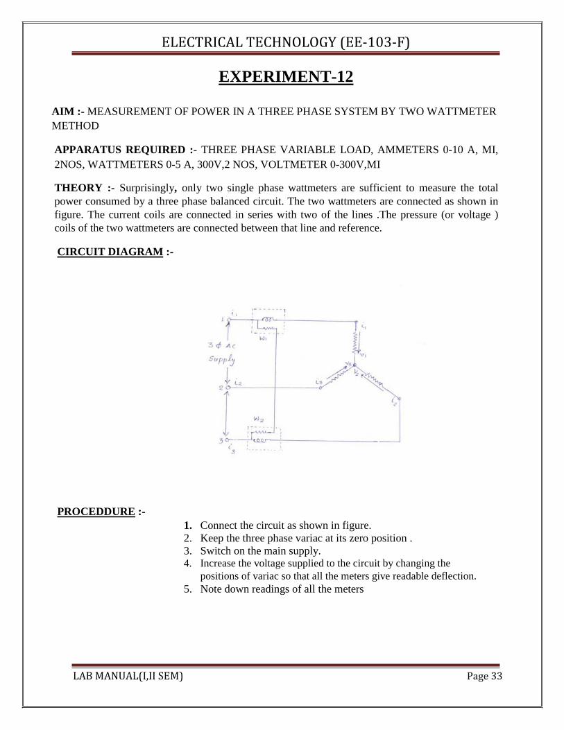
EXPERIMENT-12 AIM :- MEASUREMENT OF POWER IN A THREE PHASE SYSTEM BY TWO WATTMETER METHOD APPARATUS REQUIRED :- THREE PHASE VARIABLE LOAD, AMMETERS 0-10 A, MI, 2NOS, WATTMETERS 0-5 A, 300V,2 NOS, VOLTMETER 0-300V,MI
THEORY :- Surprisingly, only two single phase wattmeters are sufficient to measure the total power consumed by a three phase balanced circuit. The two wattmeters are connected as shown in figure. The current coils are connected in series with two of the lines .The pressure (or voltage ) coils of the two wattmeters are connected between that line and reference.
CIRCUIT DIAGRAM :-
PROCEDDURE :-
1. Connect the circuit as shown in figure. 2. Keep the three phase variac at its zero position . 3. Switch on the main supply. 4. Increase the voltage supplied to the circuit by changing the
positions of variac so that all the meters give readable deflection. 5. Note down readings of all the meters
LAB MANUAL(I,II SEM) Page 33

ELECTRICAL TECHNOLOGY (EE‐103‐F)
OBSERVATION TABLE:-
Sr.No V I W1 W2 P= W1 + W2
PRECAUTIONS :
1. Connections should be tight. 2. Take the readings carefully. 3. Switch off the circuit when not in use.
QUESTIONS/ANSWERS :-
Q.1. How many coils are there in a single in a single phase wattmeter? A. In general there are two coils in the wattmeter. One coil is known as current coil and other
coil is known as pressure coil or voltage coil.
Q.2. What do you understand by phase sequence in reference to 3-phase circuits? A. Phase sequence in three phase circuits means the order in which the phase voltages attain
their respective maximum positive voltages.
Q.3 What is the phase sequence of a 3-phase system in general? A. The phase sequence of a three phase system is R,Y, B.
Q.4 How the phase sequence of a three phase system can be changed? A. If the connections of any two phases are interchanged, the phase sequence can be changed.
Q.5 Is the method used in this experiment applicable to unbalanced loads? A. Yes, we can use this method for unbalanced loads.
Q.6 Can you measure reactive power in a three phase circuit using this method? A. Yes the reactive power is given by the relation.
Q=√3 (W1 – W2)
Q.7 Which type of wattmeter is generally used for measuring power in a.c. circuits? A. Dynamometer type of instruments are generally used for measurement of power.
Q.8 How a wattmeter is connected in an a.c. circuit? A. There are four terminals in wattmeter. There are two coils in wattmeter one is current coil
( low resistance) in wattmeter and other is pressure coil (higher resistance).The current coil is always connected in series and pressure coil is connected in parallel.
LAB MANUAL(I,II SEM) Page 34

ELECTRICAL TECHNOLOGY (EE‐103‐F)
Q.9 What is the relation between line voltage and phase voltage in star connected system? A. Line voltage is equal to √3 times of phase voltage.
Q.10 In a star connected 3-phase balanced load with neutral available, how many wattmeters
are necessary to measure power? A. Only one wattmeter is sufficient
LAB MANUAL(I,II SEM) Page 35
ELECTRICAL TECHNOLOGY (EE‐103‐F)
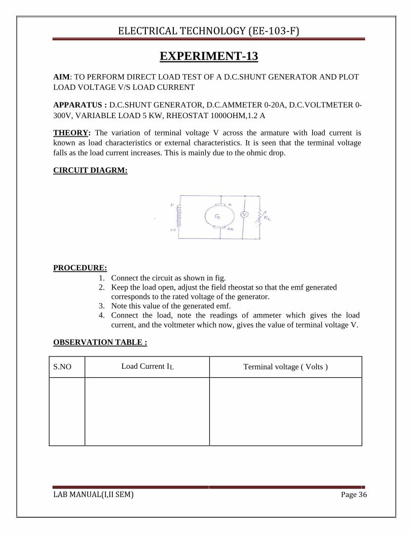
EXPERIMENT-13 AIM: TO PERFORM DIRECT LOAD TEST OF A D.C.SHUNT GENERATOR AND PLOT LOAD VOLTAGE V/S LOAD CURRENT
APPARATUS : D.C.SHUNT GENERATOR, D.C.AMMETER 0-20A, D.C.VOLTMETER 0-300V, VARIABLE LOAD 5 KW, RHEOSTAT 1000OHM,1.2 A
THEORY: The variation of terminal voltage V across the armature with load current is known as load characteristics or external characteristics. It is seen that the terminal voltage falls as the load current increases. This is mainly due to the ohmic drop.
CIRCUIT DIAGRM:
PROCEDURE:
1. Connect the circuit as shown in fig. 2. Keep the load open, adjust the field rheostat so that the emf generated
corresponds to the rated voltage of the generator. 3. Note this value of the generated emf. 4. Connect the load, note the readings of ammeter which gives the load
current, and the voltmeter which now, gives the value of terminal voltage V. OBSERVATION TABLE :
S.NO Load Current IL Terminal voltage ( Volts )
LAB MANUAL(I,II SEM) Page 36
ELECTRICAL TECHNOLOGY (EE‐103‐F)
PRECAUTIONS :
1. All the connections should be neat and tight. 2. While performing experiment, take care that the instrument readings should not exceed the ratings of the machine under test. 3. Switch off the supply when not in use
QUESTIONS/ANSWERS :-
Q.1 What is the resistance of the field winding of a d.c. shunt generator kept low? A. If the field resistance of a d.c. generator is more than particular value( critical resistance), The generator will fail to build up the voltage. For this reason, the field resistance of a d.c. shunt generator is kept low.
Q.2 What do you understand by external characteristics of a d.c. generator? A. The graph between the terminal voltage and load current is known as external characteristics of a d.c. generator, provided speed and field current remain constant.
Q.3 what will happen if the d.c. machine is operated below rated speed? A. This will result in overheating due to two reasons, first, more field current has to be maintained in order to produce the rated voltage. Second, decrease in fanning action due to decrease in speed.
Q.4 What is the most important precaution in any experiment with d.c. shunt motor? A. Before switching on d.c. supply, a sufficient resistance should be put in series with the armature of the d.c. shunt motor.
Q.5What range of speed can you get with the field control method of speed control of d.c. shunt motor? A. Speed higher than rated speed can be obtained by using this method.
Q.6 What range of speed can you get with the armature control method of speed control of d.c. shunt motor? A. Speed lower than the rated speed can be obtained by the armature control method.
Q.7 Does the direction of rotation of d.c. shunt motor would get reversed if the armature current and field current both are reversed? A. No.
Q.8 If the rated speed of a d.c. shunt motor is1440 r.p.m, which method of speed control would you suggested to obtain a speed of 1500 r.p.m? A. Field control method of speed control is suggested.
Q.9 What will happen if the d.c. shunt motor running on no-load has its shunt field winding opened accidentally?
LAB MANUAL(I,II SEM) Page 37

ELECTRICAL TECHNOLOGY (EE‐103‐F)
A. The field will be reduced to only to the value of residual flux. The speed will be very high. The parts of motor may even fly apart. Q.10 What is the most essential condition for the voltage build up for a d.c. shunt generator ? A. There should be a residual magnetism in the poles of the d.c.shunt generator. LAB MANUAL(I,II SEM) Page 38
ELECTRICAL TECHNOLOGY (EE‐103‐F)
EXPERIMENT NO. 14
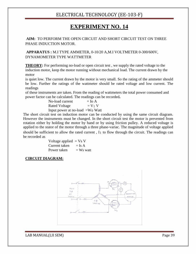
AIM: TO PERFORM THE OPEN CIRCUIT AND SHORT CIRCUIT TEST ON THREE PHASE INDUCTION MOTOR.
APPARATUS : M.I TYPE AMMETER, 0-10/20 A,M.I VOLTMETER 0-300/600V, DYNAMOMETER TYPE WATTMETER
THEORY: For performing no-load or open circuit test , we supply the rated voltage to the induction motor, keep the motor running without mechanical load. The current drawn by the motor is quiet low. The current drawn by the motor is very small. So the rating of the ammeter should be low. Further the ratings of the wattmeter should be rated voltage and low current. The readings of these instruments are taken. From the reading of wattmeters the total power consumed and power factor can be calculated. The readings can be recorded.
No-load current = Io A Rated Voltage = V1 V Input power at no-load =W0 Watt
The short circuit test on induction motor can be conducted by using the same circuit diagram. However the instruments must be changed. In the short circuit test the motor is prevented from rotation either by holding the motor by hand or by using friction pulley. A reduced voltage is applied to the stator of the motor through a three phase-variac. The magnitude of voltage applied should be sufficient to allow the rated current , I1 to flow through the circuit. The readings can be recorded as
Voltage applied = Vs V Current taken = Is A Power taken = Ws watt
CIRCUIT DIAGRAM:
LAB MANUAL(I,II SEM) Page 39

ELECTRICAL TECHNOLOGY (EE‐103‐F) PRECAUTIONS : 1. All the connections should be neat and tight.
2. The range of instruments in both the tests should be carefully selected 3. Switch off the circuit when not in use.
CONCLUSION: The No load or open circuit test and block rotor or short circuit tests can be used for parameter findings of equivalent circuit. QUESTIONS/ANSWERS :
Q.1 How do you obtain a reduced voltage from the 3-phase supply? A. Reduced voltage from a 3-phase supply is obtained by using a 3-phase variac.
Q.2 What is the output of the 3-phase induction motor working under blocked-rotor conditions? A. The output of the 3-phase induction motor working under blocked-rotor conditions is zero. Q.3 What is the output of 3-phase induction motor working under no-load conditions? A.The output of 3-phase induction motor working under no-load conditions is zero. Q.4 How much voltage is induced in the rotor circuit under no-load conditions? A. The slip under no-load conditions is quiet low and therefore the rotor induced emf is quiet low. Q.5 Why the power factor of three phase induction motor under no-load conditions is quiet low? A. The magnetizing component of no-load current is quiet high as compared to the active component of the no-load current. Due to this fact the no-load power factor is low. Q.6 What approximate fraction of rated current is the no-load current for a three phase induction motor? A. No-load current is approximately 30% of the rated current. Q.7 For performing the blocked-rotor test on a three phase induction motor. How much voltage applied to the stator of the motor? A. A reduced voltage of the order of 25% of the rated value is applied through variac for performing the blocked rotor test on a three phase induction motor. Q.8 How does the no-load current drawn by the three phase induction motor compares with the no-load current drawn by a transformer? Why? A. The no-load current drawn by the 3-phase induction motor is comparatively higher than the no-load current drawn by a transformer of equal rating. There is no-air gap in transformer In case of an induction motor there is an air gap. Ampere turns are required to overcome the reluctance of the air gap in induction motor is quiet high. It is approximately 70% of the total ampere turns. This fact accounts for a comparatively larger no-load current.
LAB MANUAL(I,II SEM) Page 40

ELECTRICAL TECHNOLOGY (EE‐103‐F) Q.9 If the rotor windings of a wound rotor are kept open, can we perform the blocked-rotor test on this machine. A. No, because as long as the rotor circuit is open, no e.m.f can be induced in the rotor. Q.10 What is the power factor of a 3-phase induction motor operating under blocked-rotor condition? A. It is quiet low i.e of the order of 0.3 lagging. LAB MANUAL(I,II SEM) Page 41
ELECTRICAL TECHNOLOGY (EE‐103‐F)
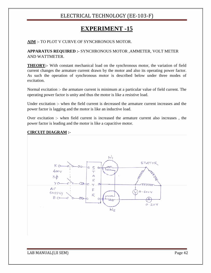
EXPERIMENT -15 AIM :- TO PLOT V CURVE OF SYNCHRONOUS MOTOR. APPARATUS REQUIRED :- SYNCHRONOUS MOTOR ,AMMETER, VOLT METER AND WATTMETER. THEORY:- With constant mechanical load on the synchronous motor, the variation of field current changes the armature current drawn by the motor and also its operating power factor. As such the operation of synchronous motor is described below under three modes of excitation. Normal excitation :- the armature current is minimum at a particular value of field current. The operating power factor is unity and thus the motor is like a resistive load. Under excitation :- when the field current is decreased the armature current increases and the power factor is lagging and the motor is like an inductive load. Over excitation :- when field current is increased the armature current also increases , the power factor is leading and the motor is like a capacitive motor. CIRCUIT DIAGRAM :- LAB MANUAL(I,II SEM) Page 42
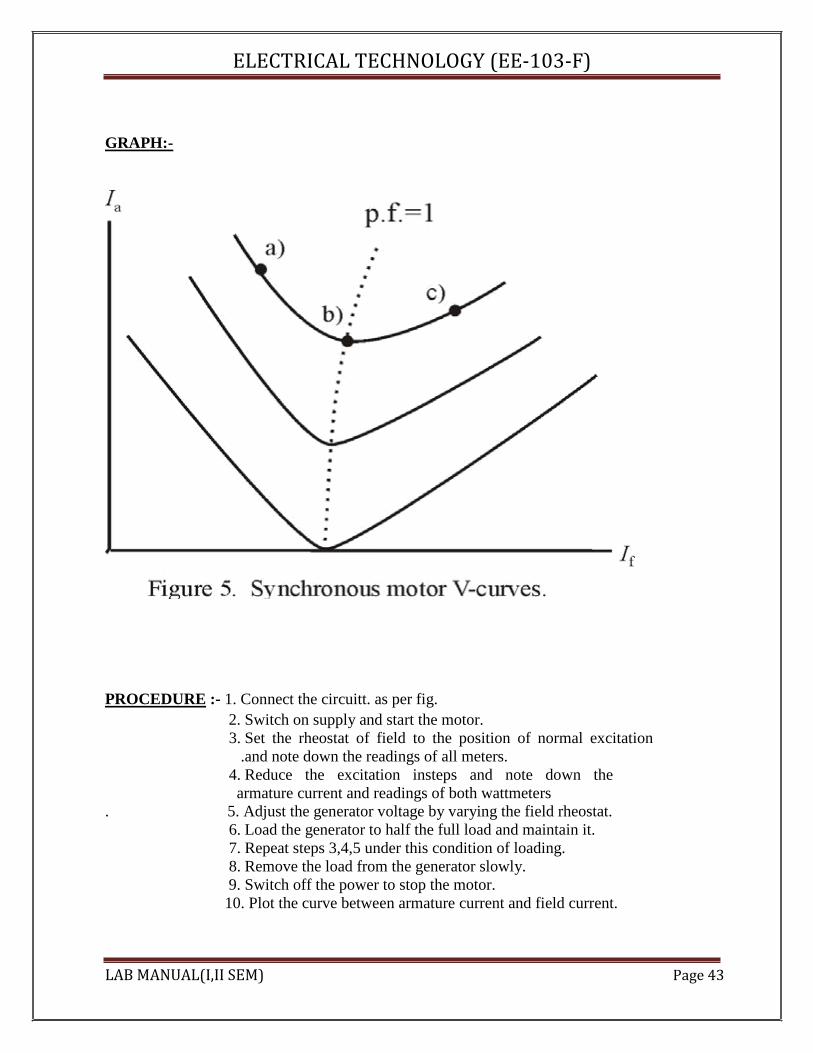
ELECTRICAL TECHNOLOGY (EE‐103‐F) GRAPH:- PROCEDURE :- 1. Connect the circuitt. as per fig.
2. Switch on supply and start the motor. 3. Set the rheostat of field to the position of normal excitation
.and note down the readings of all meters. 4. Reduce the excitation insteps and note down the armature current and readings of both wattmeters
. 5. Adjust the generator voltage by varying the field rheostat. 6. Load the generator to half the full load and maintain it. 7. Repeat steps 3,4,5 under this condition of loading. 8. Remove the load from the generator slowly. 9. Switch off the power to stop the motor. 10. Plot the curve between armature current and field current.
LAB MANUAL(I,II SEM) Page 43

ELECTRICAL TECHNOLOGY (EE‐103‐F) OBSERVATION TABLE:-
Sr.No. Ia If
PRECAUTIONS :- 1. All connections should be tight.
2. Take the readings carefully. 3. Increase and decrease the excitation voltage slowly. 4. Increase and decrease the load on generator slowly.
QUESTIONS/ANSWERS :- Q.1.Where the synchronous machines find maximum application? A. Synchronous machines find maximum application in power system.
Q 2. What is generated voltage and frequency of synchronous generator? A. The generated voltage and frequency of synchronous generator are 11 kV and 50 Hz
respectively. Q3. Why damper windings are used in synchronous machines? A .Damper windings are used in synchronous machines to reduce over voltage and damp the oscillations. Q4. Under what circumstances synchronous machine is used as industrial machine? A. Synchronous machine is used as industrial machine where constant speed is needed. Q5. What are the typical characteristics of synchronous machines? A.V curve and inverted V curve are the typical characteristics of synchronous machine. Q6. What are various excitations under which synchronous machine is operated? A. The synchronous machine is operated under normal excitation, under excitation and over
excitation. Q7. What is meant by V curve of synchronous machine? A.The curve plotted between armature current and field current is called V curve. Q8. Which type of prime movers are used for synchronous machines? A. Steam turbine and hydraulic turbines are used as prime movers for synchronous machines. LAB MANUAL(I,II SEM) Page 44
ELECTRICAL TECHNOLOGY (EE‐103‐F)
Q9. How the synchronous motor is started? A.A synchronous motor is started as an induction motor. Q10. What is operating power factor of synchronous machine under normal excitation? A. The operating power factor of synchronous motor under normal excitation is unity.
LAB MANUAL(I,II SEM) Page 45


