ELECTRICAL TECHNOLOGY (15A02306) - VEMU
60
ELECTRICAL TECHNOLOGY (15A02306) LECTURE NOTES B.TECH (II - YEAR & I - SEM) Prepared by: Mrs. M. SRUTHI, Assistant Professor Department of Electrical and Electronics Engineering VEMU INSTITUTE OF TECHNOLOGY (Approved By AICTE, New Delhi and Affiliated to JNTUA, Ananthapuramu) Accredited By NAAC & ISO: 9001-2015 Certified Institution Near Pakala, P. Kothakota, Chittoor- Tirupathi Highway Chittoor, Andhra Pradesh - 517 112 Web Site: www.vemu.org
Transcript of ELECTRICAL TECHNOLOGY (15A02306) - VEMU

ELECTRICAL TECHNOLOGY(15A02306)
LECTURE NOTES
B.TECH
(II - YEAR & I - SEM)
Prepared by:
Mrs. M. SRUTHI, Assistant Professor
Department of Electrical and Electronics Engineering
VEMU INSTITUTE OF TECHNOLOGY
(Approved By AICTE, New Delhi and Affiliated to JNTUA, Ananthapuramu)
Accredited By NAAC & ISO: 9001-2015 Certified Institution
Near Pakala, P. Kothakota, Chittoor- Tirupathi Highway
Chittoor, Andhra Pradesh - 517 112
Web Site: www.vemu.org

JAWAHARLAL NEHRU TECHNOLOGICAL UNIVERSITY ANANTAPURII B.Tech I-Sem (E.C.E) T Tu C 3 1 3
(15A02306) ELECTRICAL TECHNOLOGYObjective:
Electrical Technology contains Single phase transformers, Induction motors, DCgenerators and motors which are widely used in industry are covered and theirperformance aspects will be studied.
UNIT- I DC GENERATORS
D.C. Generators – Principle of Operation – Constructional Features – E. M.F Equation–Numerical Problems – Methods of Excitation – Separately Excited and Self ExcitedGenerators – Build-Up of E.M.F - Critical Field Resistance and Critical Speed - LoadCharacteristics of Shunt, Series and Compound Generators- Applications
UNIT – II D.C. MOTORS
D.C Motors – Principle of Operation – Back E.M.F. –Torque Equation – Characteristicsand Application of Shunt, Series and Compound Motors-Speed Control of D.C.Motors: Armature Voltage and Field Flux Control Methods. Three Point Starter-Losses– Constant & Variable Losses – Calculation of Efficiency - Swinburne’s Test.
UNIT-III SINGLE PHASE TRANSFORMERS
Single Phase Transformers - Constructional Details- Emf Equation - Operation on NoLoad and on Load - Phasor Diagrams-Equivalent Circuit - Losses and Efficiency-Regulation-OC and SC Tests – Sumpner’s Test - Predetermination of Efficiency andRegulation.
UNIT-IV 3-PHASE INDUCTION MOTORS
Polyphase Induction Motors-Construction Details of Cage and Wound RotorMachines- - Principle of Operation – Slip- Rotor Emf and Rotor Frequency - TorqueEquation- Torque Slip Characteristics.
UNIT – V SYNCHRONOUS MACHINES
Principle And Constructional Features of Salient Pole and Round Rotor Machines –E.M.F Equation- Voltage Regulation by Synchronous Impedance Method- Theory ofOperation of Synchronous Motor.
TEXT BOOKS:
1. Electric Machines –by I.J.Nagrath & D.P.Kothari,Tata Mc Graw Hill, 7th Edition.2005
2. Basic Electrical Engineering –By T.K.Nagasarkar and M.S. Sukhija OxfordUniversity Press.
REFERENCE BOOKS:
1. Electrical and Electronic Technology, Hughes, Pearson Education.
2. Electrical Machines, P. S. Bimbhra, Khanna Publishers, 2011.

3. Basic Electrical Engineering, 2nd Edition, V.N. Mittle and Aravind Mittal, Mc Grawhill Education, 2006.
Unit 1
Principle of operation of dc generator, Emf equation of dc generators, different types of dc generator,Internal external characteristics of dc generators, Construction of dc machine
1.Derive the emf equation of DC generator ? (7 M)
Emf equation for dc generator
The derivation of EMF equation for DC generator has two parts:
1. Induced EMF of one conductor 2.Induced EMF of the generator
Derivation for Induced EMF of One Armature Conductor
For one revolution of the conductor,
Let,
Φ = Flux produced by each pole in weber
(Wb) and
P = number of poles in the DC generator.
therefore, Total flux produced by all the
poles = ø*p
And,
Time taken to complete one revolution = 60/N
Where,
N = speed of the armature conductor in rpm.
Now,according to Faraday’s law of induction, the induced emf of the
armature conductor is denoted by “e” which is equal to rate of cutting the
flux.
Therefore,
Induced emf of one conductor is

Derivation for Induced EMF for DC Generator
Let us suppose there are Z total numbers of conductor in a generator, and
arranged in such a manner that all parallel paths are always in series. Here,
Z = total numbers of conductor
A = number of parallel paths
Then,
Z/A = number of conductors connected in series
We know that induced emf in each path is same
across the line Therefore,
Induced emf of DC generator
E = emf of one conductor × number of conductor connected in series.
Induced emf of DC generator is
Simple wave wound generator
Numbers of parallel paths are only 2 = A
Therefore,
Induced emf for wave type of winding generator is
Simple lap-wound generator
Here, number of parallel paths is equal to number of conductors in
one path i.e. P = A Therefore,
Induced emf for lap-wound generator is

Q2. Explain About Construction of dc machine.
Yoke of DC Generator
Yoke of DC generator serves two purposes,
1. It holds the magnetic pole cores of the generator and acts as cover of thegenerator.
2. It carries the magnetic field flux.
In small generator, yoke are made of cast iron. Cast iron is cheaper in cost
but heavier than steel. But for large construction of DC generator, where
weight of the machine is concerned, lighter cast steel or rolled steel is
preferable for constructing yoke of DC generator. Normally larger yokes are
formed by rounding a rectangular steel slab and the edges are welded
together at the bottom. Then feet, terminal box and hangers are welded to
the outer periphery of the yoke frame.
Armature Core of DC Generator
The purpose of armature core is to hold the armature winding and provide
low reluctance path for the flux through the armature from N pole to S pole.
Although a DC generator provides direct current but induced current in the
armature is alternating in nature. That is why, cylindrical or drum shaped
armature core is build up of circular laminated sheet. In every circular
lamination, slots are either die - cut or punched on the outer periphery and
the key way is located on the inner periphery as shown. Air ducts are also
punched of cut on each lamination for circulation of air through the core for
providing better cooling.
Armature Winding of DC Generator
Armature winding are generally formed wound. These are first wound in the
form of flat rectangular coils and are then pulled into their proper shape in a
coil puller. Various conductors of the coils are insulated from each other. The
conductors are placed in the armature slots, which are lined with tough
insulating material. This slot insulation is folded over above the armature
conductors placed in it and secured in place by special hard wooden or fiber
wedges.

Commutator of DC Generator
The commutator plays a vital role in dc generator. It collects current from
armature and sends it to the load as direct current. It actually takes
alternating current from armature and converts it to direct current and then
send it to external load. It is cylindrical structured and is build up of wedge -
shaped segments of high conductivity, hard drawn or drop forged copper.
Each segment is insulated from the shaft by means of insulated commutator
segment shown below. Each commutator segment is connected with
corresponding armature conductor through segment riser or lug.
Brushes of DC Generator
The brushes are made of carbon. These are rectangular block shaped. The
only function of these carbon brushes of DC generator is to collect current
from commutator segments. The brushes are housed in the rectangular box
shaped brush holder. As shown in figure, the brush face is placed on the
commutator segment with attached to the brush holder.
Bearing of DC Generator
For small machine, ball bearing is used and for heavy duty dc generator, roller bearing is used.
The bearing must always be lubricated properly for smooth operation and long life of generator.
Q3.What are the Different Methods Of Excitationof dc generators ?
An electric generator or electric motor consists of a rotor spinning in a
magnetic field. The magnetic field may be produced by permanent magnets
or by field coils. In the case of a machine with field coils, a current must flow
in the coils to generate the field, otherwise no power is transferred to or from
the rotor. The process of generating a magnetic field by means of an electric
current is called excitation.
For a machine using field coils, which is most large generators, the
field current must be supplied, otherwise the generator will be useless. Thus
it is important to have a reliable supply. Although the output of a generator
can be used once it starts up, it is also critical to be able to start the

generators reliably. In any case, it is important to be able to control the field
since this will maintain the system voltage.
TYPES OF EXCITATION
(1)seperately excited generator (2)self excited generator.
SELF GENERATOR IS CLASSIFIED INTO 3 TYPES.
1.shunt generator. 2.series generator.3.compound generator.
compoud generator is again classified into 2 types.
1.short shunt generator. 2.long shunt generator.
Separately excited generators.
These kind of generators has provided field exciter terminals which are
external DC voltage source is supplies to produce separately magnetic field
winding (shunt field) for magnetize of the generator as illustrated in figure as
below.
Self excited field generators.
This type of generator has produced a magnetic field by itself without
DC sources from an external. The electromotive force that produced by
generator at armature winding is supply to a field winding (shunt field)
instead of DC source from outside of the generator. Therefore, field winding
is necessary connected to the armature winding. They may be further
classified as

a) Shunt generator.
This generator, shunt field winding and armature winding are
connected in parallel through commutator and carbon brush as illustrated in
the figure below.
b) Series generator
The field winding and armature winding is connected in series. There is different from shunt motor due to field winding is directly connected to the electric applications (load). Therefore, field winding conductor must be sized enough to carry the load current consumption and the basic circuit as illustrated below.
c) Compound generator
The compound generator has provided with magnetic field in combine with
excitation of shunt and series field winding, the shunt field has many turns of
fine wire and caries of a small current, while the series field winding provided
with a few turns of heavy wire since it is in series with an
armature winding and caries the load current. There are two kinds of
compound generator as illustrated in figure 5 and 6.
A short-shunt compound generator

Q4.Explain O.C.C. Characteristic of separately excited generator
The generated electromotive force (EMF) is proportional to both of a
magnetic density of flux per pole and the speed of the armature rotated as
expression by the relation as following.
Eg = κ φ n
Where
K = Constant for a specific machine
φ = The density of flux per pole
n = Speed of the armature rotation
Eg = Generator voltage
By holding the armature speed (n) at a constant value it can show that
generator voltage (Eg) is directly proportional to the magnetic flux density.
Which, flux density is proportionately to the amount of field current (If). The
relation of field current and generate voltage as impressed by figure .
From the figure when the field current (If) is become zero a small generate
voltage is produce due to a residual magnetism.

As the field current increases cause to increase generated voltage linearly up
to the knee of the magnetization curve. Beyond this point by increasing the
field current still further causes saturation of the magnetic structure.
Generator voltage (Eg) is also directly to the armature speed. The formula
and a magnetization curve can be both impressed about this relation.
Where
Eg = Generator voltage or the value of EMF
at speed n Eg' = Generator voltage or the
value of EMF at speed n’ n = Speed of the
generator armature ( n’ ≠ n )
Q5.Example 1:
The open circuit terminal voltage versus the field current for a
separately excited DC generator with provided the following test data
at revolving speed 1400 rpm as show by the table1 below.
Magnetic curve for example 1
Solution

Curve (a) in figure 8 shows the characteristic at revolving speed
1400 rpm obtained by the data as show in table 1. To obtain the
characteristic at 1000 rpm, is made of the relation as Eg = Kφn
For instance, at a field current of 0.4 Amp the terminal voltage is 114
volts, when the speed is reached to 1400 rpm and kept its field current
constant at this value, the open circuit voltage at 1000 rpm becomes.
6.Define Voltage Regulation ?
Voltage Regulation
When we add load on the generator, the terminal voltage will decrease due to
(a) The armature winding resistance is mainly of armature resistance. It
is cause directly decrease in terminal voltage as following relation.
Vt = Eg - Ia Ra
Where,
Vt = Terminal or output voltage
Ia = Armature current or load current
Ra = Armature resistance
(a) Load characteristic of (b) Circuit diagram of a separately excited DC generator

The decrease in magnetic flux due to armature reaction. The armature
current establishes a magneto motive force (MMF), which it distorts to main
flux, and makes result in weakened flux. We can put inter-pole between main
field poles to reduce the armature reaction.
To have some measure by how much the terminal voltage change from
no-load condition and on load condition, which is called “voltage regulation”.
7.Critical Field Resistance And Critical Speed ? 2m
The critical field resistance is the maximum field circuit resistance for
a given speed with which the shunt generator would excite. The shunt
generator will build up voltage only if field circuit resistance is less than
critical field resistance. It is a tangent to the open circuit characteristics of
the generator at a given speed.
Suppose a shunt generator has built up voltage at a certain speed.
Now if the speed of the prime mover is reduced without changing Rf, the
developed voltage will be less as because the O.C.C at lower speed will come
down (refer to figure). If speed is further reduced to a certain critical speed
(ncr), the present field resistance line will become tangential to the O.C.C at
ncr. For any speed below ncr, no voltage built up is possible in a shunt
generator.

Critical Speed
8.Clearly explain the Load characteristics of Dc Selfexcited
Self excited DC shunt generator
A shunt generator has its shunt field winding connected in parallel with
the armature so that the machine provides it own excitation. For voltage to
build up, there must be some residual magnetism in the field poles. There
will be a small voltage (Er) generated.
(a) Shunt generator circuit (b) load characteristic of shunt generator
If the connection of the field and armature winding are such that the weak
main pole flux aids to the residual flux, the induced voltage will become
larger. Thus more voltage applied to the main field pole and cause to the
terminal voltage increase rapidly to a large value.
When we add load on the generator, the terminal voltage will decrease due
to.
a) The armature winding resistanceb)The armature reaction
b) The weakened flux due to the connection of the generator to aids or oppose to the residual

Circuit diagram for the solution of example 3
b) For a load of 20 kw when the terminal voltage is 135 volts, therefore the load current
10.Explain the characteristics of DC Series Generator ?
The field winding of a series generator is connect in series with the armature
winding. Since it carries the load current, the series field winding consists of
only a few turns of thick wire. At no-load, the generator voltage is small due

to residual field flux only. When a load is added, the flux increase, and so
does the generated voltage.
(a) Circuit diagram of series generator (b) load characteristics
Figure shows the load characteristic of a series generator driven at a certain
speed. The dash line indicated the generated EMF of the same machine with
the armature opencircuited and the field separated excited. The different
between the two curves is simply the voltage drop (IR) in the series field and
armature winding.
V t = Eg - Ia Ra + Rf
Where
Rf = The series field winding resistance
Ra = The armature winding resistance
The series generators are obviously not suited for applications requiring good
voltage regulation. Therefore, they have been used very little and only in
special applications for example, as voltage booster. The generator is placed
in series with a supply line. When the current consumption is increase, the
generated voltage of the series machine goes up because the magnetic field
current is increases.
11.Explain the Characteristics of DC Compound generator ? 10M
The compound generator has both a shunt and a series winding. The series
field winding usually wound on the top of a shunt field. The two winding are
usually connected such that their ampere-turns act in the same direction. As
such the generator is said to be cumulatively compound.

Simple circuit for compound generator
(a)Curve s is represent the terminal voltage characteristic of shunt field
winding alone. Under-compound, this condition the addition of series field
winding too short it is cause the terminal voltage no rise to certain value
and reduce while increasing in load current.
(b) Flat compound by increasing the number of a series field turns. It is
cause to rise up in terminal voltage and when no-load and full load
condition a terminal voltage is made nearly same value or equal.
(c) Over-compound, if the number of series field turns is more than
necessary to compensated of the reduce voltage. In this case while a full
load condition a terminal voltage is higher than a no-load voltage.
Therefore over-compound generator may use where load is at some
distance from generator. Voltage drop in the line has compensated by
used of an over-compound generator.
(d) If a reversing the polarity of the series field occur this cause to the
relation between series field and shunt field, the field will oppose to each
other more and more as the load current increase. Therefore terminal
voltage will drop, such generator is said to be a differentially compound.
The compound generator are used more extensively than the other type
of dc generator because its design to have a wide variety of terminal voltage
characteristics.
12. Define Machine Efficiency ? 2m
The efficiency of any machine is the ratio of the ratio of the output power to
the input power. The input power is provided by the prime mover to drive the
generator. Because part of the energy delivered to the generator is

converted into heat, it represents wasted energy. These losses are generally
minimized in the design stage; however, some of these losses are
unavoidable.
13. Clearly Explain about Different Losses of a Dc Machine ?
The losses of generators may be classified as
1) Copper lossesThe copper losses are present because of the resistance of the windings.
Currents flowing through these windings create ohmic losses. The
windings that may be present in addition to the (I2 R ) armature winding
are the field windings, inter-pole and compensate windings.
2) Iron lossesAs the armature rotates in the magnetic field, the iron parts of thearmature as well as the conductors cut the magnetic flux. Since iron is agood conductor of electricity, the EMF s induced in the iron parts coursesto flow through these parts. These are the eddy currents. Another lossoccurring in the iron is due to the Hysteresis loss is present in thearmature core.
Other rotational losses consist of 3.1 bearing friction loss
3.2 friction of the rushes riding on the commutator
3.3 windage losses
Windage losses are those associated with overcoming air friction in setting
up circulation currents of air inside the machine for cooling purposes. These
losses are usually very small
14.Write a brief notes on Applications Of Dc Generators ? 10M
Applications of Separately Excited DC Generators
These types of DC generators are generally more expensive than self-excited
DC generators because of their requirement of separate excitation source.
Because of that their applications are restricted. They are generally used
where the use of self-excited generators are unsatisfactory.
1. Because of their ability of giving wide range of voltage output, they are
generally used for testing purpose in the laboratories.

2. Separately excited generators operate in a stable condition with any
variation in field excitation. Because of this property they are used as
supply source of DC motors, whose speeds are to be controlled for
various applications. Example- Ward Leonard Systems of speed control.
Applications of Shunt Wound DC Generators
The application of shunt generators are very much restricted for its
dropping voltage characteristic. They are used to supply power to the
apparatus situated very close to its position. These type of DC generators
generally give constant terminal voltage for small distance operation with
the help of field regulators from no load to full load.
1. They are used for general lighting. 2.They are used to charge battery because they can be made to give constant output voltage. 3.They are used for giving the excitation to the alternators.4.They are also used for small power supply.
Applications of Series Wound DC Generators
These types of generators are restricted for the use of power supply
because of their increasing terminal voltage characteristic with the increase
in load current from no load to full load. We can clearly see this characteristic
from the characteristic curve of series wound generator. They give constant
current in the dropping portion of the characteristic curve. For this property
they can be used as constant current source and employed for various
applications
1.They are used for supplying field excitation current in DC locomotives
for regenerative breaking.
2.This types of generators are used as boosters to compensate the voltage
drop in the feeder in various types of distribution systems such as railway
service.
3.In series arc lightening this type of generators are mainly used.
Applications of Compound Wound DC Generators
Among various types of DC generators, the compound wound DC
generators are most widely used because of its compensating property. We

can get desired terminal voltage by compensating the drop due to armature
reaction and ohmic drop in the in the line. Such generators have various
applications.
1. Cumulative compound wound generators are generally used lighting,
power supply purpose and for heavy power services because of their
constant voltage property. They are mainly made over compounded.
2. Cumulative compound wound generators are also used for driving a motor.
3. For small distance operation, such as power supply for hotels, offices,
homes and lodges, the flat compounded generators are generally used.
4. The differential compound wound generators, because of their large
demagnetization armature reaction, are used for arc welding where huge
voltage drop and constant current is required.
At present time the applications of DC generators become very limited
because of technical and economic reasons. Now a days the electric power
is mainly generated in the form of alternating current with the help of
various power electronics devices.
==============******* THE END *********============
UNIT-II
DC MOTORS
1.Explain the Principle of operation of Dc motor ?
Consider a coil in a magnetic field of flux density B (figure ). When the
two ends of the coil are connected across a DC voltage source, current I
flows through it. A force is exerted on the coil as a result of the interaction of
magnetic field and electric current. The force on the two sides of the coil is
such that the coil starts to move in the direction of force.

Fig.1. Torque production in a DC motor
In an actual DC motor, several such coils are wound on the rotor, all of
which experience force, resulting in rotation. The greater the current in the
wire, or the greater the magnetic field, the faster the wire moves because of
the greater force created.
At the same time this torque is being produced, the conductors are
moving in a magnetic field. At /dt) as shown indifferent positions, the flux
linked with it changes, which causes an emf to be induced (e = d figure 5.
This voltage is in opposition to the voltage that causes current flow through
the conductor and is referred to as a counter-voltage or back emf.
Fig.2. Induced voltage in the armature winding of DC motor
The value of current flowing through the armature is dependent upon the
difference between the applied voltage and this counter-voltage. The current
due to this counter-voltage tends to oppose the very cause for its production
according to Lenz’s law. It results in the rotor slowing down. Eventually, the
rotor slows just enough so that the force created by the magnetic field (F =
Bil) equals the load force applied on the shaft. Then the system moves at
constant velocity.
2.Deduce the formula for Different Torques in DC motor ? 10M
Torque Developed
The turning or twisting moment of a force about an axis is called torque. It
is measured by the product of the force and the radius at which this force
acts.
Consider a pulley of radius meter acted upon by a circumferential force of
newton which causes it to rotate at rpm.

Armature torque of a motor
Shaft torque

What is back emf ? 2 m
Induced Counter-voltage (Back emf):
Due to the rotation of this coil in the magnetic field, the flux linked with
it changes at different positions, which causes an emf to be induced (refer to
figure 2).
The induced emf in a single coil, e = døc/dt
Since the flux linking the coil, c = Sin
Induced voltage , e = cost (1)
Note that equation (4) gives the emf induced in one coil. As there are several
coils wound all around the rotor, each with a different emf depending on the
amount of flux change through it, the total emf can be obtained by summing
up the individual emfs.
The total emf induced in the motor by several such coils wound on the rotor
can be obtained by integrating equation (4), and expressed as:
Eb = K m (2)
where K is an armature constant, and is related to the geometry and
magnetic properties of the motor, and m is the speed of rotation.
The electrical power generated by the machine is given by:
Pdev = Eb Ia = Km
Ia (3)
Draw the equivalent circuit of dc motor ? 2m
Fig.1. DC motor representation
Explain the importance of Counter EMF in DC motor ? 10m

When voltage is applied to dc motor, current will flow into the positive brush
through the commutator into the armature winding. The motor armature
winding is identical to the generator armature winding. Thus the conductors
on the north field poles are carry current in one direction, while all
conductors on the south field poles carry the current in opposite direction.
When the armature carry current it will produce a magnetic field around the
conductor of it own which interact with the main field. It is cause to the force
developed on all conductors and tending to turn the armature.
The armature conductors continually cut through this resultant field. So
that voltages are generated in the same conductors that experience force
action. When operating the motor is simultaneously acting as generator.
Naturally motor action is stronger than generator action.
Although the counter EMF is opposite with the supplied voltage, but it
cannot exceed to applied voltage. The counter EMF is serves to limit the
current in an armature winding. The armature current will be limited to the
value just sufficient to take care of the developed power needed to drive the
load.
In the case of no load is connected to the shaft. The counter EMF will almost
equal to the applied voltage. The power develops by the armature in this
case is just the power needed to overcome the rotational losses. It’s mean
that the armature current IA is controlled and limited by counter EMF
therefore
Where:
VL = Line voltage across the armature winding
Ra = Resistance of the armature winding
Ea = Induced EMF or generated voltage
Ia = Armature current
Since, EA is induced or generated voltage it is depend on the flux per poleand the speed of the armature rotate (n) in rpm.
Therefore

E a = K φ n
Where:
K = the constant value depending on armature winding and number of pole of machine.
φ = Rotation of the armature
Where:
Z = Total number of conductor in the armature winding
a = Number of parallel circuit in the armature winding between positive andnegative brushes. For wave wound armature “a” = 2
Lap wound armature “a” = P
Distinguish armature and field speed control methods ? 10 M
Speed control of DC motor Many applications require the speed of a motor to be varied over a wide range. One of the most attractive features of DC motors in comparison with AC motors is the ease with which their speed can be varied.
We know that the back emf for a separately excited DC motor:
From the above equation, it is evident that the speed can be varied by using
any of the following methods:
Armature voltage control (By varying VT) Field Control (By Varying ) Armature resistance control (By varying Ra)
Armature voltage control
This method is usually applicable to separately excited DC motors. In
this method of speed control, Ra and are kept constant.In normal
operation, the drop across the armature resistance is small compared to
Eb and therefore: Eb VT

Since, Eb = Kø ωm
Angular speed can be expressed as:
ωm= VT/ Kø (8)
From this equation, If flux is kept constant, the speed changes linearly with VT.
As the terminal voltage is increased, the speed increases and vice versa.The relationship between speed and applied voltage is shown in figure 8. This
method provides smooth variation of speed control.
Fig.8.Variation of speed with applied voltage
Field Control , ( )
In this method of speed control, Ra and VT remain fixed.
Therefore, from equation (7):
mI/
Assuming magnetic linearity, If
(OR) m I/IF (9)
i.e., Speed can be controlled by varying field current If.
The field current can be changed by varying an adjustable rheostat in
the field circuit (as shown in figure 9).
By increasing the value of total field resistance, field current can be
reduced, and therefore speed can be increased.

The relationship between the field winding current and angular speed is shown in figure 10
Fig.10: Variation of speed with field current
Armature Resistance Control
The voltage across the armature can be varied by inserting a variable resistance in series with the armature circuit.
Fig.11. Armature resistance method for speed control
From speed-torque characteristics , we know that:
For a load of constant torque VT and are kept constant, as the armature
resistance Ra is increased, speed decreases. As the actual resistance of the
armature winding is fixed for a given motor, the overall resistance in the
armature circuit can be increased by inserting an additional variable
resistance in series with the armature. The variation if speed with respect to
change in this external resistance is shown in figure 12. This method
provides smooth control of speed.
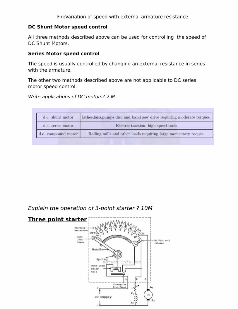
Fig:Variation of speed with external armature resistance
DC Shunt Motor speed control
All three methods described above can be used for controlling the speed of DC Shunt Motors.
Series Motor speed control
The speed is usually controlled by changing an external resistance in series with the armature.
The other two methods described above are not applicable to DC series motor speed control.
Write applications of DC motors? 2 M
Explain the operation of 3-point starter ? 10M
Three point starter

The figure above shows that typical representation diagram of a 3 point
starter for DC shunt motors with its protective devices. It contains 3
terminals namely L, Z, & A; hence named 3 point starter. The starter is made
up of of starting resistances divided into many section and which are
connected in series within the armature. The each tapping point on the
starting resistances is carried out to a no. of studs. The starter 3 terminals
L,Z & A are connected to the positive terminal of line, shunt field and
armature terminal of motor respectively. The remaining terminal of the shunt
and armature are connected to the negative line terminal. The No volt coil
release is connected in series with field winding. The handle one end is
connected to the L terminal by means of over load release coil. Then another
end of handle travels against the twisting spring & make touching base with
every single stud in the course of starting operation, tripping out the starting
resistance as it moves above every stud in clockwise.
Clearly explain about swimburns test how will u calculate efficiency of a dc machine .discuss merits and demerits ? 10 M
Swinburne’s Test for DC Machines
In this technique, the DC Generator or DC Motor is run as a motor at no load;
with that losses of the DC machines are determined. When the losses of DC
machine well-known, then we can find the efficiency of a DC machine in
advance at any desired load. In DC machines this test is applicable only
throughout the flux is constant at all load (DC Shunt machine and DC
Compound Machine). This test maintains of two steps;
Determination of Constant Losses:

On no load the DC machine run as a motor with the supply voltage is varied to the normal rated voltage. With the use of the field regulator R the motor speed is varied to run the rated speed which is shown in the figure.
Let
V = Supply Voltage
I0 = No load current read by A1
Ish = Shunt Field current ready by A2
No load armature current Iao = I0 – Ish
No load Input power to motor = VI0
No load Input power to motor = VIa0
= V (I0 – Ish)
As the output power is nil, the no loads input power to the armature provides
Iron loss, armature copper loss, friction loss and windage loss.
Constant loss Wc = Input power to Motor – Armature copper loss
Wc = VI0 – (I0 – Ish2Ra)
As the constant losses are identified, the efficiency of the DC machine at any
loads can be determined. Suppose it is desired to determine the DC machine
efficiency at no load current. Then, Armature current Ia = I-Ish (For Motoring)
Ia = I+Ish (For Generating)
To find the Efficiency when running as a motor:
Input power to motor = VI
Armature copper loss =Ia2Ra = (I-Ish2Ra)
Constant Loss = Wc
Total Loss = (I-Ish2Ra)+Wc
Motor Efficiency η = (Input power – Losses)/ Input
η= VI – (I-Ish2Ra) / VI
Condition for maximum Efficiency in DC MachineTo find the Efficiency when running as a Generator:
Output Power of Generator = VI

Armature copper loss =Ia2Ra = (I+Ish2Ra)
Constant Loss = Wc
Total Loss = (I+Ish2Ra)+Wc
Motor Efficiency η= Output power/ (Output power + Losses)
η = VI / VI + (I+Ish2Ra) + Wc
Merits:
Since this test is no load test, power required is less. Hence the cost is economic.
The efficiency of the machine can be found very easily, because the
constant losses are well known.
This test is appropriate.Demerits:
When the DC machine is loaded, this test does not deliberate the stray
load loss that occurs.
Using this method we cannot check the DC machine performances at full load.
UNIT-III
SINGLE PHASE TRANSFORMERS
Constructional Details- Emf Equation -Operation on No Load and on Load - -Equivalent Circuit
-Losses and Efficiency-Regulation-OC and SC Tests -Sumpner’s Test -Predetermination of
Efficiency and Regulation.

PRINCIPLE OF OPERATION OF A SINGLE PHASE TRANSFORMER
A single phase transformer works on the principle of mutual induction
between two magnetically coupled coils. When the primary winding is
connected to an alternating voltage of r.m.s value, V1 volts, an alternating
current flows through the primary winding and setup an alternating flux ϕ, in
the material of the core. This alternating flux ϕ, links not only the primary
windings but also
the secondary windings. Therefore, an e.m.f e1 is induced in the
primary winding and an e.m.f e2 is induced in the secondary winding, e1 and
e2 are given:
If the induced e.m.f is e1 and e2 are represented by their rms values E1 and E2 respectively, then
K is known as the transformation ratio of the transformer. When a load is connected to the secondary winding, a current I2 flows through the load, V2 is the terminal voltage across the load. As the power transfered from the primary winding to the secondary winding is same, Power input to the primary winding = Power output from the secondary winding.

The directions of emf‘s E1 and E2 induced in the primary and secondary
windings are such that, they always oppose the primary applied voltage V1.
Deduce EMF equation of a Transformer ? 10M
EMF Equation of a transformer:
Consider a transformer having,
N1 =Primary turns
N2 = Secondary turns
Φm = Maximum flux in the core
Φm = Bm × A webers
f= frequency of ac input in hertz (Hz)
i.e, E1 =4.44fφm×N1 = 4.44fBm×A×N1
Similarly;
E2= 4.44 f φm × N2 = 4.44 f Bm × A × N2
Clearly explain the operation of transformer at NO and ON load ? 10M
TRANSFORMER ON NO-LOAD
Theory of Transformer On No-load, and Having No Winding
Resistance and No Leakage Reactance of Transformer
Let us consider one electrical transformer with only core losses, which
means, it has only core losses but no copper loss and no leakage reactance
of transformer. When an alternating source is applied in the primary, the
source will supply the current for magnetizing the core of transformer.
But this current is not the actual magnetizing current, it is little bit greater
than actual magnetizing current. Actually, total current supplied from the
source has two components, one is magnetizing current which is merely
utilized for magnetizing the core and other component of the source current
is consumed for compensating the core losses in transformer. Because of this
core loss component, the source current in transformer on no-load
condition supplied from the source as source current is not exactly at 90°
lags of supply voltage, but it lags behind an angle θ is less than 90°. If total
current supplied from source is Io, it will have one component in phase with
supply voltage V1 and this component of the current Iw is core loss
component. This component is taken in phase with source voltage, because
it is associated with active or working losses in transformer. Other
component of the source current is denoted as Iμ. This component produces
the alternating magnetic flux in the core, so it is watt-less; means it is
reactive part of the transformer source current. Hence Iμ will be in quadrature
with V1 and in phase with alternating flux Φ.
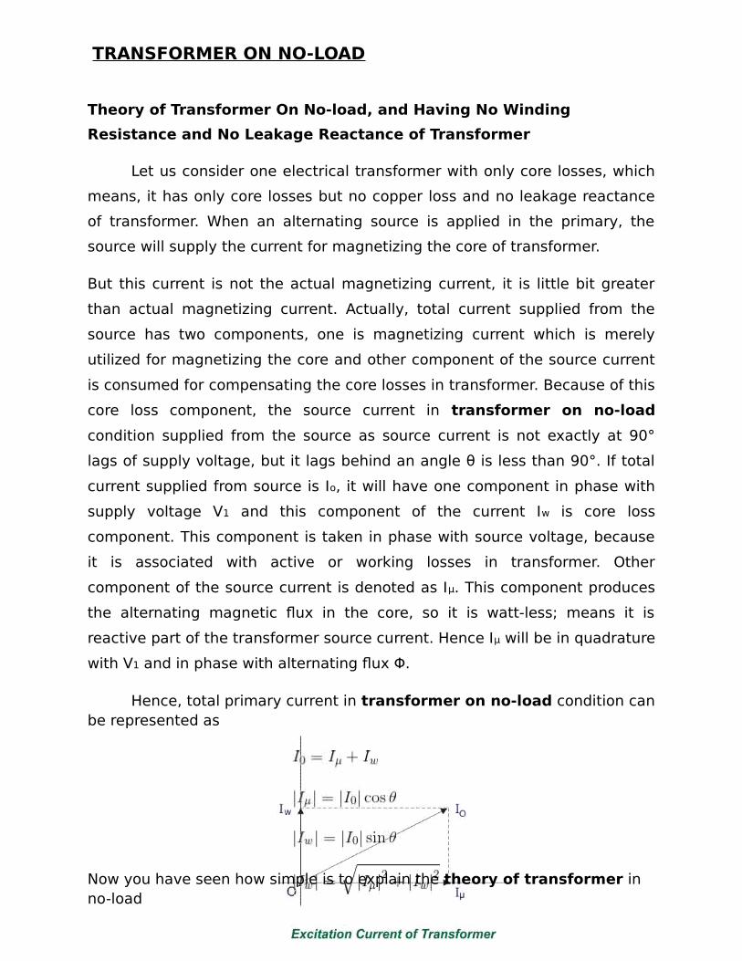
Hence, total primary current in transformer on no-load condition canbe represented as
Now you have seen how simple is to explain the theory of transformer in no-load

TRANSFORMER ON LOAD
Theory of Transformer On Load But Having No Winding Resistance and Leakage
Reactance
Now we will examine the behavior of above said transformer on load, that means load is
connected to the secondary terminals. Consider, transformer having core
loss but no copper loss and leakage reactance. Whenever load is connected
to the secondary winding, load current will start to flow through the load as
well as secondary winding. This load current solely depends upon the
characteristics of the load and also upon secondary voltage of the
transformer. This current is called secondary current or load current, here it is
denoted as I2. As I2 is flowing through the secondary, a self mmf in secondary
winding will be produced. Here it is N2I2, where, N2 is the number of turns of
the secondary winding of transformer.

This mmf or magneto motive force in the secondary winding produces flux
φ2. This φ2 will oppose the main magnetizing flux and momentarily weakens
the main flux and tries to reduce primary self induced emf E1. If E1 falls down
below the primary source voltage V1, there will be an extra current flowing
from source to primary winding. This extra primary current I2′ produces
extra flux φ′ in the core which will neutralize the secondary counter flux φ2.
Hence the main magnetizing flux of core, Φ remains unchanged irrespective
of load.
So total current, this transformer draws from source can be divided into
two components, first one is utilized for magnetizing the core and
compensating the core loss i.e. Io. It is no-load component of the primary
current. Second one is utilized for compensating the counter flux of the
secondary winding. It is known as load component of the primary current.
Hence total no load primary current I1 of a electrical power transformer
having no winding resistance and leakage reactance can be represented as
follows
Where θ2 is the angle between Secondary Voltage and Secondary Current of
transformer. Now we will proceed one further step toward more practical
aspect of a transformer.
Transformer On Load, With Resistive Winding, But No Leakage Reactance
Now, consider the winding resistance of transformer but no leakage
reactance. So far we have discussed about the transformer which has ideal
windings, means winding with no resistance and leakage reactance, but now
we will consider one transformer which has internal resistance in the winding
but no leakage reactance. As the windings are resistive, there would be a
voltage drop in the windings.

We have proved earlier that, total primary current from the source on load is
I1. The voltage drop in the primary winding with resistance, R1 is R1I1.
Obviously, induced emf across primary winding E1, is not exactly equal to
source voltage V1. E1 is less than V1 by voltage drop I1R1.
Again in the case of secondary, the voltage induced across the secondary
winding, E2 does not totally appear across the load since it also drops by an
amount I2R2, where R2 is the secondary winding resistance and I2 is
secondary current or load current.
Similarly, voltage equation of the secondary side of the transformer will be
Theory of Transformer On Load, With Resistance As Well As Leakage
Reactance in Transformer Windings Now we will consider the condition,
when there is leakage reactance of transformer as well as winding resistance
of transformer.
Let leakage reactances of primary and secondary windings of the
transformer are X1 and X2 respectively.
Hence total impedance of primary and secondary winding of transformer
with resistance R1 and R2 respectively, can be represented as,
We have already established the voltage equation of a transformer on
load, with only resistances in the windings, where voltage drops in the
windings occur only due to resistive voltage drop. But when we consider
leakage reactances of transformer windings, voltage drop occurs in the
winding not only because of resistance, it is because of impedance of
transformer windings. Hence, actual voltage equation of a transformer can
easily be determined by just replacing resistances R1 & R2 in the previously
established voltage equations by Z1 and Z2.
Therefore, the voltage equations are,
Resistance drops are in the direction of current vector but, reactive drop will
be perpendicular to the current vector as shown in the above vector
diagram of transformer.
How u can estimated efficiency and voltage regulation of a transformer from O.C and S.C
tests ? 10 M
O.C. and S.C. Tests on Single Phase Transformer
The efficiency and regulation of a transformer on any load condition and
at any power factor condition can be predetermined by indirect loading

method. In this method, the actual load is not used on transformer. But the
equivalent circuit parameters of a transformer are determined by conducting
two tests on a transformer which are,
1.Open circuit test (O.C Test)
2.Short circuit test (S.C.Test)
The parameters calculated from these test results are effective in
determining the regulation and efficiency of a transformer at any load and
power factor condition, without actually loading the transformer. The
advantage of this method is that without much power loss the tests can be
performed and results can be obtained. Let us discuss in detail how to
perform these tests and how to use the results to calculate equivalent circuit
parameters.
Open Circuit Test (O.C. Test)
The experimental circuit to conduct O.C test is shown in the Fig. 1.
Fig 1. Experimental circuit for O.C. test
The transformer primary is connected to a.c. supply through ammeter,
wattmeter and variac. The secondary of transformer is kept open. Usually
low voltage side is used as primary and high voltage side as secondary to
conduct O.C test.

The primary is excited by rated voltage, which is adjusted precisely with
the help of a variac. The wattmeter measures input power. The ammeter
measures input current. The voltemeter gives the value of rated primary
voltage applied at rated frequency.
Sometimes a voltmeter may be connected across secondary to measure
secondary voltage which is V2 = E2 when primary is supplied with rated
voltage. As voltmeter resistance is very high, though voltmeter is connected,
secondary is treated to be open circuit as voltmeter current is always
negligibly small.
When the primary voltage is adjusted to its rated value with the help of
variac, readings of ammeter and wattmeter are to be recorded.
Let,
Vo = Rated voltage
Wo = Input power
Io = Input current = no load current
As transformer secondary is open, it is on no load. So current drawn by the
primary is no load current Io. The two components of this no load current are,
Im = Io sin Φo
Ic = Io cos Φo
where cos Φo = No load power factor
And hence power input can be written as,
Wo = Vo Io cos Φ
The phasor diagram is shown in the Fig.
Fig.

As secondary is open, I2 = 0. Thus its reflected current on primary is also
zero. So we have primary current I1 =Io. The transformer no load current is
always very small, hardly 2 to 4 % of its full load value. As I2 = 0, secondary
copper losses are zero. And I1 = Io is very low hence copper losses on
primary are also very very low. Thus the total copper losses in O.C. test are
negligibly small. As against this the input voltage is rated at rated frequency
hence flux density in the core is at its maximum value. Hence iron losses are
at rated voltage. As output power is zero and copper losses are very low, the
total input power is used to supply iron losses. This power is measured by the
wattmeter i.e. Wo. Hence the wattmeter in O.C. test gives iron losses
which remain constant for all the loads.
Wo = Pi= Iron losse Calculations : We know that,
Wo = Vo Io cos Φ
cos Φo = Wo /(Vo Io ) = no load power factor
Once cos Φo is known we can obtain,
Ic = Io cos Φo

and Im = Io sin Φo
Once Ic and Im are known we can determine exciting circuit parameters as,
Ro = Vo /Ic Ω
and Xo = Vo /Im Ω
Key Point : The no load power factor cos Φo is very low hence wattmeter used must be low power factor type otherwise there might be error in the results. If the meters are connected on secondary and primary is kept open then from O.C. test we get Ro'and Xo' with which we can obtain Ro and Xo knowing the transformation ratio K.
Short Circuit Test (S.C. Test)
In this test, primary is connected to a.c. supply through variac, ammeter
and voltmeter as shown in the Fig. 3.
Experimental circuit for O.C. test
The secondary is short circuited with the help of thick copper wire or solid
link. As high voltage side is always low current side, it is convenient to
connect high voltage side to supply and shorting the low voltage side.
As secondary is shorted, its resistance is very very small and on rated
voltage it may draw very large current. Such large current can cause
overheating and burning of the transformer. To limit this short circuit current,
primary is supplied with low voltage which is just enough to cause rated
current to flow through primary which can be observed on an ammeter. The
low voltage can be adjusted with the help of variac. Hence this test is also
called low voltage test or reduced voltage test. The wattmeter reading as
well as voltmeter, ammeter readings are recorded.

Now the current flowing through the windings are rated current hence
the total copper loss is full load copper loss. Now the voltage supplied is low
which is a small fraction of the rated voltage. The iron losses are function of
applied voltage. So the iron losses in reduced voltage test are very small.
Hence the wattmeter reading is the power loss which is equal to full load
copper losses as iron losses are very low.
...Wsc = (Pcu) F.L. = Full load copper loss
Calculations : From S.C. test readings we can write,
Wsc = Vsc Isc cos Φsc
... cos Φsc = Vsc Isc /Wsc = short circuit power factor
Wsc = Isc2 R1e = copper loss
... R1e =Wsc /Isc2
while Z1e =Vsc /Isc = √(R1e2 + X1e
2)
Calculation of Efficiency from O.C. and S.C. Tests
We know that, From O.C. test, Wo = Pi
From S.C. test, Wsc = (Pcu) F.L.
Thus for any p.f. cos Φ2 the efficiency can be predetermined. Similarly at
any load which is fraction of full load then also efficiency can be
predetermined as,
where n = fraction of full load
where
I2= n (I2) F.L.

Calculation ofRegulation
From S.C. test we get the equivalent circuit parameters referred to primary or secondary.
The rated voltages V1, V2 and rated currents (I1) F.L. and (I2) F.L. are
known for the given transformer. Hence the regulation can be determined
as,
where I1, I2 are rated currents for full load regulation.
For any other load the currents I1, I2 must be changed by fraction n.
... I1, I2 at any other load = n (I1) F.L., n (I2) F.L.
Question: A 5 KVA, 500/250 V, 50 Hz, single phase transformer gavethe following readings,
O.C. Test : 500 V, 1 A, 50 W (L.V. side open)
S.C. Test : 25 V, 10 A, 60 W (L.V. side shorted)
Determine : i) The efficiency on full load, 0.8 lagging p.f.
ii) The voltage regulation on full load, 0.8 leading p.f.iii) The efficiency on 60% of full load, 0.8 leading p.f.iv)Draw the equivalent circuit referred to primary and insert all the values in
it.
Solution : In both the tests, meters are on H.V. side which is primary of the
transformer. Hence the parameters obtained from test results will be
referred to primary.
From O.C. test,Vo = 500 V, Io = 1 A, Wo= 50 W
... cos Φo = Wo/Vo Io = 50/(500x1) = 0.1
...
Ic = Io cos = 1 x 0.1 = 0.1 A
and Im = Io sin Φo = 1 x 0.9949 = 0.9949 A

... Ro =Vo /Ic = 500/0.1 = 5000 Ω
and Xo = Vo/Im = 500/0.9949 = 502.52 Ω
and Wo = Pi= iron losses = 50 W
From S.C. test, Vsc = 25 V, Isc = 10 A, W
... R1e = Wsc /Isc2 = 60/(10)
Z1e = Vsc /Isc = 25/10 = 2.5 Ω
... X1e= √(2.52 - 0.62) = 2.4269 Ω
(I1) F.L. = VA rating/V1
= (5 x 10³ )/500 = 10 A
and Isc = (I1) F.L.
... Wsc = (Pcu) F.L. = 60 W
i) η on full load, cos = 0.8 lagging
ii) Regulation on full load, cos Φ2 = 0.8 leading
=- 1.95 %
iii) For 60% of full load, n = 0.6 and cos Φ2 = 0.8 leading]
... Pcu = copper loss on new load = n2 x (Pcu) F.L.
= (0.6)2 x 60 = 21.6 W
= 97.103 %iv)The equivalent circuit referred to primary is shown in the Fig. 4
UNIT-IV
3-PHASE INDUCTION MOTORS
Poly phase Induction Motors-Construction Details of Cage and Wound Rotor Machines-
Principle of Operation -Slip- Rotor Emf and Rotor Frequency -Torque Equation -Torque SlipCharacteristics.
Question 1. Explain the principle of operation of 3-ɵ induction motor ?
Principle of OperationThe operation of a 3-phase induction motor is
based upon the application of Faraday Law and the Lorentz force on a
conductor. The behaviour can readily be understood by means of the
following example.
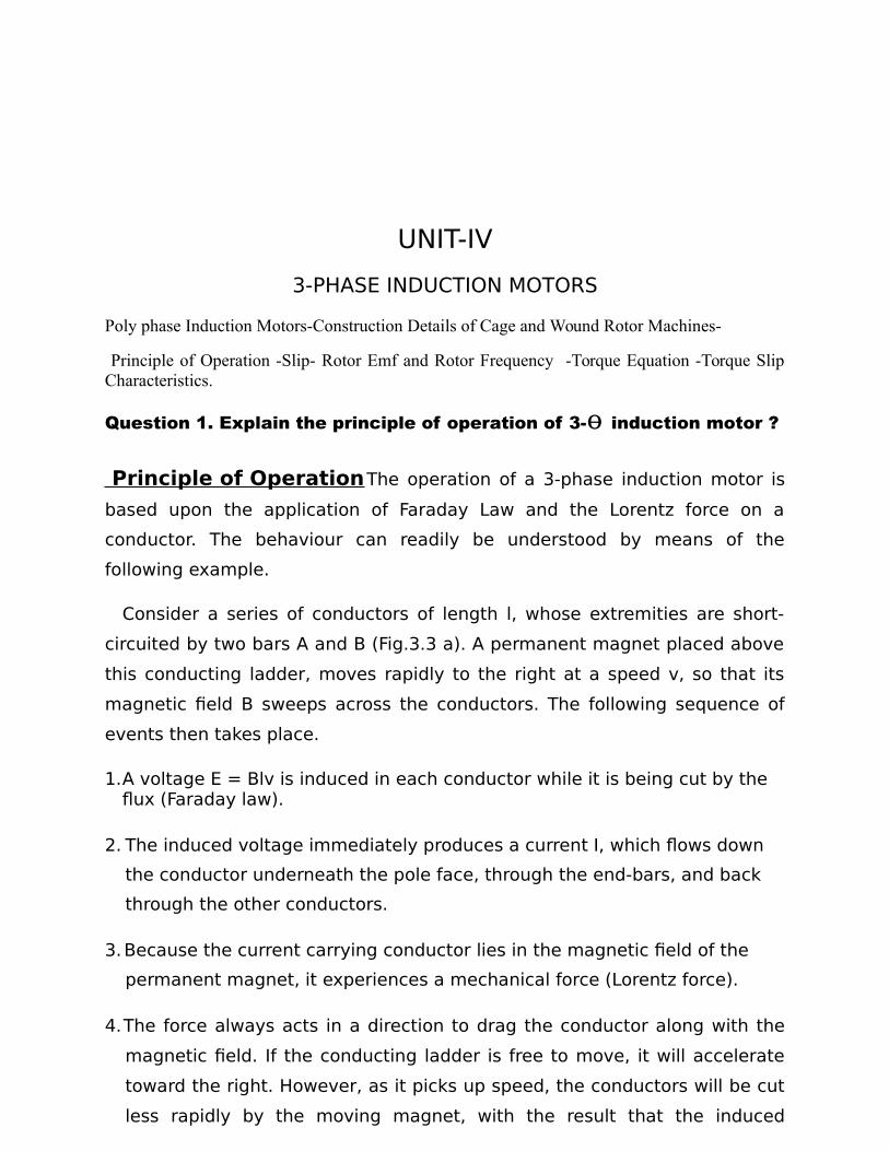
Consider a series of conductors of length l, whose extremities are short-
circuited by two bars A and B (Fig.3.3 a). A permanent magnet placed above
this conducting ladder, moves rapidly to the right at a speed v, so that its
magnetic field B sweeps across the conductors. The following sequence of
events then takes place.
1.A voltage E = Blv is induced in each conductor while it is being cut by the flux (Faraday law).
2. The induced voltage immediately produces a current I, which flows down
the conductor underneath the pole face, through the end-bars, and back
through the other conductors.
3.Because the current carrying conductor lies in the magnetic field of the
permanent magnet, it experiences a mechanical force (Lorentz force).
4.The force always acts in a direction to drag the conductor along with the
magnetic field. If the conducting ladder is free to move, it will accelerate
toward the right. However, as it picks up speed, the conductors will be cut
less rapidly by the moving magnet, with the result that the induced

voltage E and the current I will diminish. Consequently, the force acting on
the conductors wilt also decreases. If the ladder were to move at the same
speed as the magnetic field, the induced voltage E, the current I, and the
force dragging the ladder along would all become zero.
In an induction motor the ladder is closed upon itself to form a squirrel-
cage (Fig.3.3b) and the moving magnet is replaced by a rotating field. The
field is produced by the 3-phase currents that flow in the stator windings.
Question 2 :Derive torque Equation of 3phase induction motor ?
Snatch the characteristics of sliptorque ?

Slip:
F
requency of rotor curre
TORQUE EQUATION

Starting torque
The torque developed by the motor at the instant of starting is called startingtorque.

Fig. Effect of rotor resistance on torque-speed characteristic
TORQUE – SPEED CHARACTERISTICS
For small values of slip s, the torque is directly proportional to s.
For large values of slip s, the torque is inversely proportional to s.
Fig. Complete torque-speed characteristic of a three phase inductionmachine
Question 3:Distinguish squirrel cage and slip ring induction motor


UNIT – V SYNCHRONOUS MACHINES
Principle And Constructional Features of Salient Pole and Round Rotor Machines-E.M.F
Equation-Voltage Regulation by Synchronous Impedance Method- Theory of Operation of
Synchronous Motor.
1.Explain the principle of operation of AC Synchronous motor ?
Theory of operation of synchronous motor
Electrical motor in general is an electro-mechanical device that
converts energy from electrical domain to mechanical domain. Based on the
type of input we have classified it into single phase and 3 phase motors.
Among 3 phase induction motors and synchronous motors are more widely
used. When a 3 phase electric conductors are placed in a certain geometrical
positions (In certain angle from one another) there is an electrical field
generate. Now the rotating magnetic field rotates at a certain speed, that
speed is called synchronous speed. Now if an electromagnet is present in this
rotating magnetic field, the electromagnet is magnetically locked with this
rotating magnetic field and rotates with same speed of rotating field.
Synchronous motors is called so because the speed of the rotor of this
motor is same as the rotating magnetic field. It is basically a fixed speed
motor because it has only one speed, which is synchronous speed and
therefore no intermediate speed is there or in other words it’s in synchronism
with the supply frequency. Synchronous speed is given by
2.Write a short notes about Constructional Details of AC Machine? With
principle of operation ?
There are mainly two types of rotor used in construction of alternator,
1. Salient pole type.2. Cylindrical rotor type.CONSTRUCTION OF SALIENT POLE ROTOR MACHINES
The construction of a synchronous motor(with salient pole rotor) is as
shown in the figure at left. Just like any other motor, it consists of a stator
and a rotor. The stator core is constructed with thin silicon lamination and
insulated by a surface coating, to minimize the eddy current and hysteresis

losses. The stator has axial slots inside, in which three phase stator winding
is placed.
The stator is wound with a three phase winding for a specific number of poles
equal to the rotor poles.
The rotor in synchronous motors is mostly of salient pole type. DC supply is
given to the rotor winding via slip-rings. The direct current excites the rotor
winding and creates electromagnetic poles. In some cases permanent
magnets can also be used. The figure above illustrates the construction of a
synchronous motor very briefly.
Fig. Salient pole synchronous machine
Working principle of salient pole synchronous machine
The stator is wound for the similar number of poles as that of rotor,and fed with three phase AC supply. The 3 phase AC supply produces rotatingmagnetic field in stator. The rotor winding is fed with DC supply whichmagnetizes the rotor. Consider a two pole synchronous machine as shownin figure below.
Now, the stator poles are revolving with synchronous speed (lets sayclockwise). If the rotor position is such that, N pole of the rotor is near the Npole of the stator (as shown in first schematic of above figure), then thepoles of the stator and rotor will repel each other, and the torque producedwill be anticlockwise.
The stator poles are rotating with synchronous speed, and they rotate
around very fast and interchange their position. But at this very soon,
rotor can not rotate with the same angle (due to inertia), and the next
position will be likely the second schematic in above figure. In this case,

poles of the stator will attract the poles of rotor, and the torque
produced will be clockwise.
Fig. Salient pole rotor
Hence, the rotor will undergo to a rapidly reversing torque, and the
motor will not start. But, if the rotor is rotated upto the synchronous speed of
the stator by means of an external force (in the direction of revolving field of
the stator), and the rotor field is excited near the synchronous speed, the
poles of stator will keep attracting the opposite poles of the rotor (as the
rotor is also, now, rotating with it and the position of the poles will be similar
throughout the cycle). Now, the rotor will undergo unidirectional torque. The
opposite poles of the stator and rotor will get locked with each other, and the
rotor will rotate at the synchronous speed.
The salient features of pole field structure has the following special feature-
1. They have a large horizontal diameter compared to a shorter axial length.
2. The pole shoes covers only about 2/3rd of pole pitch.3. Poles are laminated to reduce eddy current loss.4. The salient pole type motor is generally used for low speed operations of
around 100 to 400 rpm, and they are used in power stations with hydraulic turbines or diesel engines.
Construction of round (or) cylindrical rotor synchronous machine
Fig. Round (or) cylindrical rotor

The cylindrical rotor is generally used for very high speed operation
and are employed in steam turbine driven alternators like turbo generators.
The cylindrical rotor type machine has uniform length in all directions, giving
a cylindrical shape to the rotor thus providing uniform flux cutting in all
directions. The rotor in this case consists of a smooth solid steel cylinder,
having a number of slots along its outer periphery for hosing the field coils.
The cylindrical rotor alternators are generally designed for 2-pole type
giving very high speed of Ns = (120 × f)/P = (120 × 50) / 2 = 3000 rpm. Or
4-pole type running at a speed of Ns = (120 × f) / P = (120 × 50) / 4 = 1500
rpm. Where f is the frequency of 50 Hz.
The a cylindrical rotor synchronous generator does not have any projections
coming out from the surface of the rotor, rather central polar area are
provided with slots for housing the field windings as we can see from the
diagram above. The field coils are so arranged around these poles that flux
density is maximum on the polar central line and gradually falls away as we
move out towards the periphery. The cylindrical rotor type machine gives
better balance and quieter-operation along with lesser windage losses.
Construction of Synchronous Motor
Normally it's construction is almost similar to that of a 3 phase
induction motor, except the fact that the rotor is given dc supply, the reason
of which is explained later. Now, let us first go through the basic construction
of this type of motor.
From the above picture, it is clear that how this type of motors are designed.
The stator is given is given three phase supply and the rotor is given dc
supply.
3. evaluate the effiency of an AC machine By SIM method ?
Voltage regulation by synchronous impedance method
This method is also called E.M.F. method of determining the regulation. The
method requires following data to calculate the regulation.
1.The armature resistance per phase (Ra).
2. Open circuit characteristics which is the graph of open circuit voltage
against the field current. This is possible by conducting open circuit
test on the alternator.
3. Short circuit characteristics which is the graph of short circuit current
against field current. This is possible by conducting short circuit test on
the alternator.
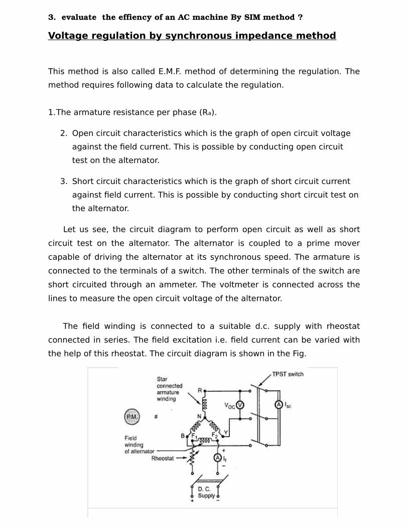
Let us see, the circuit diagram to perform open circuit as well as short
circuit test on the alternator. The alternator is coupled to a prime mover
capable of driving the alternator at its synchronous speed. The armature is
connected to the terminals of a switch. The other terminals of the switch are
short circuited through an ammeter. The voltmeter is connected across the
lines to measure the open circuit voltage of the alternator.
The field winding is connected to a suitable d.c. supply with rheostat
connected in series. The field excitation i.e. field current can be varied with
the help of this rheostat. The circuit diagram is shown in the Fig.

Open Circuit Test
Procedure to conduct this test is as follows :
i) Start the prime mover and adjust the speed to the synchronous speed of the alternator.
ii) Keeping rheostat in the field circuit maximum, switch on the d.c. supply.
iii) The T.P.S.T switch in the armature circuit is kept open.
iv) With the help of rheostat, field current is varied from its minimum
value to the rated value. Due to this, flux increasing the induced e.m.f.
Hence voltmeter reading, which is measuring line value of open circuit
voltage increases. For various values of field current, voltmeter
readings are observed.
Note : This is called open circuit characteristics of the alternator, called
O.C.C. This is shown in the Fig.
Fig. O.C.C. and S.C.C. of an alternator
Short Circuit Test
After completing the open circuit test observation, the field rheostat is
brought to maximum position, reducing field current to a minimum value.
The T.P.S.T switch is closed. As ammeter has negligible resistance, the
armature gets short circuited. Then the field excitation is gradually increased
till full load current is obtained through armature winding. This can be
observed on the.
ammeter connected in the armature circuit. The graph of short circuit
armature current against field current is plotted from the observation table of
short circuit test. This graph is called short circuit characteristics, S.C.C. This
is also shown in the Fig.
The S.C.C. is a straight line graph passing through the origin while
O.C.C. resembles B-H curve of a magnetic material.
Note : As S.C.C. is straight line graph, only one reading corresponding to full
load armature current along with the origin is sufficient to draw the straight
line.
Determination of From O.C.C. and S.C.C.
The synchronous impedance of the alternator changes as load condition
changes. O.C.C. and S.C.C. can be used to determine Zs for any load and load
p.f. conditions.
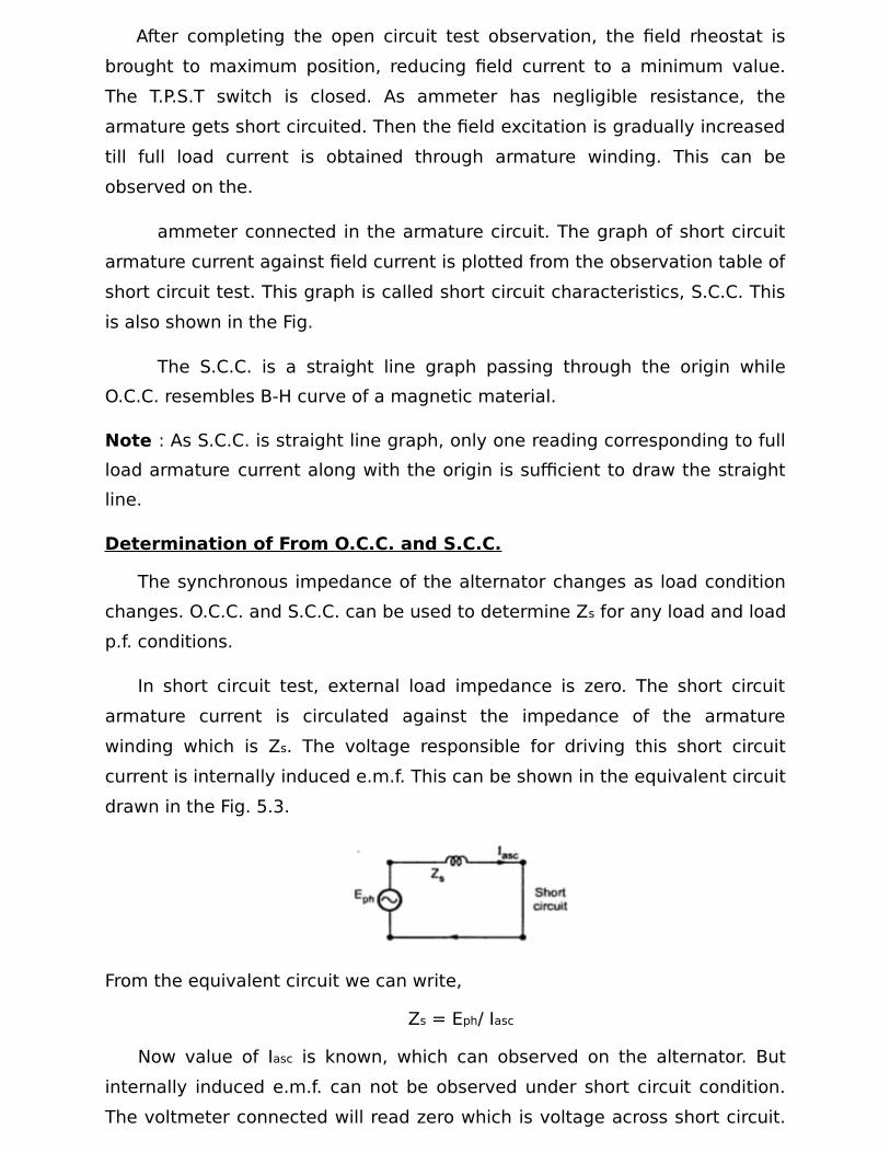
In short circuit test, external load impedance is zero. The short circuit
armature current is circulated against the impedance of the armature
winding which is Zs. The voltage responsible for driving this short circuit
current is internally induced e.m.f. This can be shown in the equivalent circuit
drawn in the Fig. 5.3.
From the equivalent circuit we can write,
Zs = Eph/ Iasc
Now value of Iasc is known, which can observed on the alternator. But
internally induced e.m.f. can not be observed under short circuit condition.
The voltmeter connected will read zero which is voltage across short circuit.

To determine Zs it is necessary to determine value of E which is driving Iasc
against Zs.
So if the terminal of the alternator are opened without disturbing If which
was present at the time of short circuited condition, internally induced e.m.f.
will remain same as Eph. But now current will be zero. Under this condition
equivalent circuit will become as shown in the Fig.
It is clear now from the equivalent circuit that as Ia = 0 the voltmeter reading
(Voc)ph will be equal to internally induced e.m.f. (Eph).
This is what we are interested in obtaining to calculate value of Zs. So
expression for Zs can be modified as,
So O.C.C. and S.C.C. can be effectively to calculate Zs.
The value of Zs is different for different values of If as the graph of O.C.C. is
non linear in nature. So suppose Zs at full load is required then,
Iasc = full load current.
From S.C.C. determine If required to drive this full load short circuit Ia.
This is equal to 'OA', as shown in the Fig.2.
Now for this value of If, (Voc)ph can be obtained from O.C.C. Extend kine
from point A, till it meets O.C.C. at point C. The corresponding (Voc)ph value
is available at point D.
Voc)ph = OD
While (Iasc)ph = OE

at full load
General steps to determine Zs at any load condition are :
i) Determine the value of (Iasc)ph for corresponding load condition. This
can be determined from known full load current of the alternator. For
half load, it is half of the full load value and so on.
ii) S.C.C. gives relation between (Iasc)ph and If. So for (Iasc)ph required,
determine the corresponding value of If from S.C.C.
iii) Now for this same value of If, extend the line on O.C.C. to get the value
of (Voc)ph. This is (Voc)ph for same If, required to drive the selected
(Iasc)ph.
iv) The ratio of (Voc)ph and (Iasc)ph, for the same excitation gives the value
of Zs at any load conditions.
The graph of synchronous impedance against excitation current is also shown in the Fig. 2.
Regulation Calculations
From O.C.C. and S.C.C., Zs can be determined for any load condition.
The armature resistance per phase (Ra) can be measured by different methods. One of the method is applying d.c. known voltage across the two terminals and measuring current. So value of Ra per phase is known.
So synchronous reactance per phase can be determined.
No load induced e.m.f. per phase, Eph can be determined by the
mathematical expression derived earlier.
where Vph = Phase value of rated voltage
Ia = Phase value of current depending on the
load condition cosΦ = p.f. of load
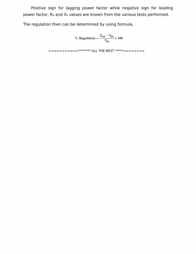
Positive sign for lagging power factor while negative sign for leading
power factor, Ra and Xs values are known from the various tests performed.
The regulation then can be determined by using formula,
===========******** ALL THE BEST *****========