ELECTRICAL SYSTEMS SPECIFICATIONS RCH INTEGRATED INTERVENTIONAL OR ROYAL COLUMBIAN ... ·...
134
ELECTRICAL SYSTEMS SPECIFICATIONS for RCH INTEGRATED INTERVENTIONAL OR ROYAL COLUMBIAN HOSPITAL NEW WESTMINSTER, B.C. Architect: CEI Architecture Planning Interiors 500 – 1500 West Georgia Street Vancouver, BC V6G 2Z6 Phone: (604) 687-1898 Fax: (604) 682-5398 Stantec Consulting Ltd. 1100 – 111 Dunsmuir Street Vancouver, BC V6B 6A3 Phone: (604) 696-8000 Fax: (604) 696-8100 File: 115640774 SEPTEMBER 08, 2009 – ISSUED FOR TENDER Copyright 2009 Stantec Consulting Ltd. All rights reserved. These documents may not be copied, photocopied, reproduced, translated, or reduced to any electronic medium or machine-readable form, in whole or in part, without the prior written consent of Stantec Consulting Ltd.
Transcript of ELECTRICAL SYSTEMS SPECIFICATIONS RCH INTEGRATED INTERVENTIONAL OR ROYAL COLUMBIAN ... ·...

ELECTRICAL SYSTEMS SPECIFICATIONS
for
RCH INTEGRATED INTERVENTIONAL OR ROYAL COLUMBIAN HOSPITAL
NEW WESTMINSTER, B.C.
Architect:
CEI Architecture Planning Interiors 500 – 1500 West Georgia Street
Vancouver, BC V6G 2Z6 Phone: (604) 687-1898
Fax: (604) 682-5398
Stantec Consulting Ltd. 1100 – 111 Dunsmuir Street
Vancouver, BC V6B 6A3 Phone: (604) 696-8000
Fax: (604) 696-8100
File: 115640774
SEPTEMBER 08, 2009 – ISSUED FOR TENDER
Copyright 2009 Stantec Consulting Ltd. All rights reserved. These documents may not be copied, photocopied, reproduced, translated, or reduced to any electronic medium or machine-readable form, in whole or in part, without the prior written consent of Stantec Consulting Ltd.

RCH Integrated Interventional OR Royal Columbian Hospital New Westminster, B.C.
Section 16000Electrical Specification Table Of Contents
Page 1 of 2
Stantec Consulting Ltd. 115640774
Section No. Description Pages
Section 16010 General Electrical Provisions 1-7
Section 16020 Work Included 1-2
Section 16021 Related Work Specified Elsewhere 1
Section 16025 Codes and Fees 1
Section 16031 Operation and Maintenance Manuals 1-2
Section 16032 Demonstration and Instruction Sessions for 1
Electrical Equipment and Systems
Section 16033 Electrical Spare Parts and Maintenance Materials 1
Section 16040 Identification 1-5
Section 16045 Seismic Restraints 1-4
Section 16111 Conduit 1-3
Section 16116 Surface Raceways and Fittings 1
Section 16120 Wire and Cable 1-3
Section 16130 Outlet Boxes 1-2
Section 16131 Pull and Junction Boxes 1
Section 16140 Switches 1
Section 16142 Dimmers 1
Section 16145 Receptacles 1-2
Section 16147 Plates 1
Section 16152 Supporting Devices 1
Section 16160 Grounding 1-3
Section 16433 Transformers – Dry Type 1-2
Section 16475 Overcurrent Protective Devices 1-3

RCH Integrated Interventional OR Royal Columbian Hospital New Westminster, B.C.
Section 16000Electrical Specification Table Of Contents
Page 2 of 2
Stantec Consulting Ltd. 115640774
Section No. Description
Section 16501 General Requirements for Lighting 1-2
Section 16505 Lamps 1
Section 16509 Ballasts and Accessories 1-2
Section 16510 Luminaires 1-2
Section 16540 Exit Lights 1
Section 16605 Miscellaneous Equipment Wiring 1
Section 16685 Patient Care Area Installations 1-3
Section 16700 General Provisions for Electronic / Computerized Equipment 1-2
Section 16705 Fire Alarm System 1-8
Section 16730 GPS Clock System 1
Section 16732 Nurse Call System 1-8
Section 16743 Data / Voice Cabling System 1-9
Section 16799 Testing and Training 1-2
Section 16901 Motors 1
Section 16905 Motor Starters 1-2
Section 16909 Disconnects 1
Section 16917 Motor Control Centres 1-3
Appendix:
RCH – Shop Drawings Revision 4 9.4.09
RCH – Skyvision Conduit Drawing
RCH – Skytron Aurora II Electrical Details
RCH – Skyvision Hybrid II Site Requirements
END OF INDEX

RCH Integrated Interventional OR Royal Columbian Hospital New Westminster, B.C.
Section 16010General Electrical Provisions
Page 1 of 7
Stantec Consulting Ltd. 115640774
1 GENERAL
1.1 Section Includes .1 Division 16 to provide all labour and materials necessary for complete and operating
electrical systems as indicated on the drawings and specified herein. Any work, even if not shown or specified, which is obviously necessary or reasonably implied to complete the work to be done as if it was both shown and specified.
1.2 Standards Of Material And Workmanship .1 All materials to be new, of minimum quality specified and conform to standards of
Canadian Standards Association. Where equipment or materials are specified by technical description only, they are to be of the best commercial quality obtainable for the purpose.
.2 All work to be executed in a neat and workmanlike manner by qualified tradesmen. Division 16 to keep a competent foreman and all necessary assistants, all satisfactory to the Owner, on the job during progress of the work. Where reference is made to standards such as EEMAC, NEMA, CSA, IPCEA, the latest editions and revisions of such standard specifications to apply.
.3 All electrical equipment to be CSA approved. Electrical equipment that is shown on the drawings or called for in the specifications that is not CSA approved is to be treated by Division 16 in one of the following ways:
.1 make allowance in Contract Price for having said equipment CSA approved, or
.2 make allowance in Contract Price for most expensive CSA approved equivalent. .4 Reference Section 01600.
1.3 Record Drawings .1 Division 16 to maintain one set of contract drawing white prints, including all
supplementary and revision drawings on site, solely for the purpose of recording, in red line, any change and/or deviation from the Contract Drawings as it occurs. Include elevations and detailed locations of all services.
.2 Comply with requirements indicated in Section 01300.
.3 The marked-up set of prints shall be reviewed on site monthly by the consultant during the construction process. This review will form a requirement for approval of the monthly progress claim.
.4 The Record Drawings shall include, but not limited to, the following changes and shall be recorded daily:
.1 Location of all underground conduit runs that project through foundation wall and elevation of same.
.2 Location and routing of all underfloor conduit runs below grade.
.3 Location and routing of all ceiling conduit runs.
.4 Location, routing and elevation of all conduit runs associated with street lighting, exterior receptacles and signs.
.5 Include all details from revision drawings, addenda, and change orders. Label each drawing in the lower right corner in letters of at least 12mm [1/2"] high as follows: “AS BUILT DRAWINGS", Contractors name and date.
.5 CAD Drafting:

RCH Integrated Interventional OR Royal Columbian Hospital New Westminster, B.C.
Section 16010General Electrical Provisions
Page 2 of 7
Stantec Consulting Ltd. 115640774
.1 The Consultant will transfer the Red Line Record Drawing information into CAD format at no cost to the Contractor. This work will be done as a direct service to the Owner.
1.4 Uniformity Of Equipment .1 Unless otherwise specifically called for in the specifications, uniformity of manufacturer to
be maintained throughout the building for any particular item or type of equipment. .2 Reference Section 01600.
1.5 Compliance Of Equipment With Specifications .1 Division 16 to be completely responsible for ascertaining that every item included in
Contract complies in all respects with specifications and drawings. Any item of equipment found by Owner not to comply with specifications and drawings to be replaced at no additional cost with an item or unit of the Owner's choice.
.2 Refer to Division 1.
1.6 Drawings And Specifications .1 Drawings and specifications are complementary each to the other and what is called for
by one to be binding as if called for by both. Should any discrepancy appear between drawings and specifications which leaves doubt as to the true intent and meaning, obtain a ruling from the Consultant.
.2 Electrical drawings indicate general location and route to be followed by conduits and/or wire and do not show all structural and mechanical details. In some cases, conduit or wiring is not shown on drawings or is shown diagrammatically in schematic or riser diagrams. Conduit and wire to be installed to provide a complete operating job and to be installed physically to conserve headroom, furring spaces, etc.
.3 Follow architectural, structural and mechanical drawings for details of this work and install electrical conduit, boxes and fittings to coordinate with architectural, structural and mechanical work and details. Refer to architectural and structural drawings for accurate building dimensions.
.4 In order to provide sufficient detail and maximum degree of clarity on the drawings, symbols used for various electrical devices, particularly wall mounted devices, take up more space on the drawings than the device does on the wall. In these instances, locate device on wall with primary regard for convenience of operation and usage of wall space, rather than stringing devices out along wall so as to comply with scale locations of electrical symbols.
1.7 Examination Of Other Drawings .1 Examine structural, architectural and mechanical drawings and work of other trades to
ensure that work can be satisfactorily carried out without changes to building as shown on drawings. Conflicts or additional work beyond work covered by drawings and specifications to be brought to attention of the Consultant.
.2 Reference Section 01100.
1.8 Location Of Outlets .1 Owner reserves the right to change location of outlets to within 3 m of points indicated on
drawings without extra charge providing Division 16 is advised prior to installation. .2 Location of outlets shown on architectural detail drawings takes precedence over
positions or mounting heights located on electrical drawings and/or in the specifications.

RCH Integrated Interventional OR Royal Columbian Hospital New Westminster, B.C.
Section 16010General Electrical Provisions
Page 3 of 7
Stantec Consulting Ltd. 115640774
1.9 Mounting Heights Of Equipment .1 Installation of electrical equipment in ceiling spaces to be coordinated with other trades in
order not to restrict access to the ceiling voids above the installed electrical services. .2 Unless otherwise noted on the drawings or in the specifications, mounting heights for
electrical devices to be as follows: .1 Switches: 1050 mm to centre. .2 Receptacles: 500 mm above floor and 150 mm above counter and open shelves
or centred in between shelves in millwork areas. Millwork desks with grommets in the counter tops need the receptacle devices to be installed below desk heights. See Architectural Millwork Details.
.3 Communication Outlets: 500 mm above floor and 150 mm above counter and open shelves or centred in between shelves in millwork areas, 1550 mm where indicated with symbol "W".
.4 Bells, Buzzers: 300 mm below ceiling. Maximum mounting height 2900 mm.
.5 Clocks: 450 mm below ceiling to centre. Maximum mounting height 2900 mm.
.6 Fire Alarm pullstations: 1200 mm.
.7 All mounting heights refer to the centre of the device. .3 Check architectural drawings for room details, dados, built-in units, etc. to avoid conflicts. .4 Reference Section 01700.
1.10 Contract Breakdown .1 Within 14 days after award of Contract, Division 16 to submit a breakdown of Contract
Price into divisions to the satisfaction of the Consultant with aggregate of breakdown totalling total Contract amount. Breakdown will be used in computing of progress claims. Progress claims, when submitted are to be itemized against each item of the Contract breakdown. Contract breakdown to be of material and labour as listed herein:
.1 Emergency power and normal power incoming feeders
.2 600/120/208V Transformers
.3 347/600V Distribution
.4 All 347/600V and 120/208V Panelboards
.5 Motor Control Centres
.6 Miscellaneous Mechanical Equipment and Mechanical Equipment Wiring
.7 Conduit, Boxes and Wire
.8 Lighting – Building
.9 Voice / Data cabling
.10 Fire Alarm System
.11 Clocks
.12 Low voltage lighting controls
.13 Nurses call systems
.14 Operation and Maintenance Manuals, Testing
1.11 Ordering Material .1 All materials to be ordered promptly upon award of Contract. Material delivery date not
to delay construction schedule. Material not to be accepted from suppliers who cannot meet specified date. When requested, provide evidence of ordering of material.
.2 Reference Section 01600.

RCH Integrated Interventional OR Royal Columbian Hospital New Westminster, B.C.
Section 16010General Electrical Provisions
Page 4 of 7
Stantec Consulting Ltd. 115640774
1.12 Shop Drawings .1 Submit shop drawings of all electrical components as required by the Consultant.
Approval of shop drawings is for general design only and does not relieve Division 16 and/or his supplier or manufacturer from complying with all requirements of drawings plans and specifications. Division 16 to be responsible for conforming to and coordinating all dimensions. Division 16 to take note that any shop drawing revisions required after the second review shall be at expense of Division 16.
.2 Prior to submission, all shop drawings to be stamped, dated and signed by both Division 16 and the Contractor.
.3 Division 16 to coordinate each shop drawing submission with requirements of the contract documents. Individual drawings will not be reviewed until all related shop drawings and product data is available.
.4 Division 16 to review shop drawings and assume responsibility for: .1 Completeness - including all details specified. .2 Dimensions, field measurements. .3 Catalogue numbers and similar data. .4 Conformance with contract documents. .5 Colours. .6 Site conditions. .7 Interference with mechanical equipment including motor sizes and loads,
equipment locations and connection points. .5 Shop drawing submissions to include:
.1 Name of Contractor, Subcontractor, Supplier and Manufacturer.
.2 Date and revision dates.
.3 Project name.
.4 All pertinent data.
.5 Dimensions.
.6 Colour.
.7 Specification section number.
.8 Contractor's stamp and Division 16's stamp.
.9 A clear space of 100 mm x 75 mm on each sheet for placement of the Owner's review stamp. Each sheet to be numbered sequentially.
.10 Model and type numbers. .6 Shop drawings will not be reviewed if they:
.1 Are not clearly legible.
.2 Do not contain all information required above.
.3 Describe other products or models not applicable to this project. .7 Submit for review after the award of the contract, one reproducible print and number of
copies of shop drawings as directed by the Consultant. .8 Luminaire shop drawings (both fluorescent and high intensity discharge) to include:
.1 Replacement ballast shop drawings.
.2 Replacement lamp data. .9 Include with shop drawing submittal, detailed prestartup check lists, startup/post-startup
procedures and check lists for each piece of equipment and for each system. .10 Submit shop drawings on all wiring devices, relays and motor controls. .11 Do not order material or equipment until the Consultant has reviewed shop drawings. .12 Maintain on site, one complete indexed copy of all reviewed shop drawings.

RCH Integrated Interventional OR Royal Columbian Hospital New Westminster, B.C.
Section 16010General Electrical Provisions
Page 5 of 7
Stantec Consulting Ltd. 115640774
1.13 Sprinklered Rooms .1 In rooms where electrical equipment is installed surface mounted, electrical equipment
contained in these rooms to be protected by non-combustible driphoods, shields, and gasketed doors as applicable to inhibit water ingression into electrical equipment. Exposed conduits connected to equipment to utilize watertight connectors. Top entry to be avoided where possible.
1.14 Phasing Of Work .1 Division 16 to familiarize himself with schedules established for the various phases of the
work. This schedule, together with time allotments is outlined in Division 1. .2 Electrical tender price to include allowance for delays caused to the electrical contract
due to phasing of the project. .3 Reference Section 01310.
1.15 Timing Of Work .1 Work involving alterations, connections to or extensions of existing power distribution, fire
alarm, telephone, public address, etc. to be carried out in such a manner to keep interruptions of service to existing systems to a minimum. Division 16 to allow necessary overtime work to accomplish changeovers and reconnections at a time when existing building is at a minimum of use. The Contractor should be aware of, and include any associated costs, relating to last minute delays of critical changeovers such as power shut downs that may be cancelled at the last minute due to unforeseen emergency patient care.
.2 Division 16 to provide a comprehensive schedule and detailed written confirmation of procedures for review by the Owner. Interruptions to operation of the facility will not be allowed without a pre-arranged pre-activity meeting with all affected parties to the proposed interruption. Identify outage times and durations for each service outage. Outages to be scheduled at the Owner's convenience. No disconnection or isolation of services is to take place without 72 hours notice and approval of the Owner.
.3 If required to maintain services to certain areas or keep outages to an acceptable minimum, Division 16 to make such temporary connections and provide such temporary facilities as are required to accomplish this.
.4 Division 16 to allow in tender price for premium and overtime charges as required to accommodate conditions as outlined in the preceding paragraphs and specifically addressed in various sections of the specifications.
1.16 Temporary Usage .1 New luminaires not to be used during construction. .2 New luminaires to be tested by Division 16 and de-energized until substantial completion. .3 Should any luminaires be used during construction, then:
.1 Relamp all new luminaires with new lamps (do not use spare lamps).
.2 Provide five (5) new ballasts per 100 ballasts used per year of operation. .4 New distribution equipment used for construction purposes to have the manufacturer's
warranty extended for a period of one year from date of substantial performance. .5 Construction-Use Receptacle Power - At such time as the building power systems
become available, the contractor to provide and install construction-use receptacles - brown in colour - as required throughout building for contractor use. Construction usage of permanently installed receptacles (stainless steel) will not be allowed. Immediately
RCH Integrated Interventional OR Royal Columbian Hospital New Westminster, B.C.
Section 16010General Electrical Provisions
Page 6 of 7
Stantec Consulting Ltd. 115640774
prior to substantial performance, replace all brown construction-use receptacles with permanent receptacles specified in tender documents.
.6 Reference Section 01500.
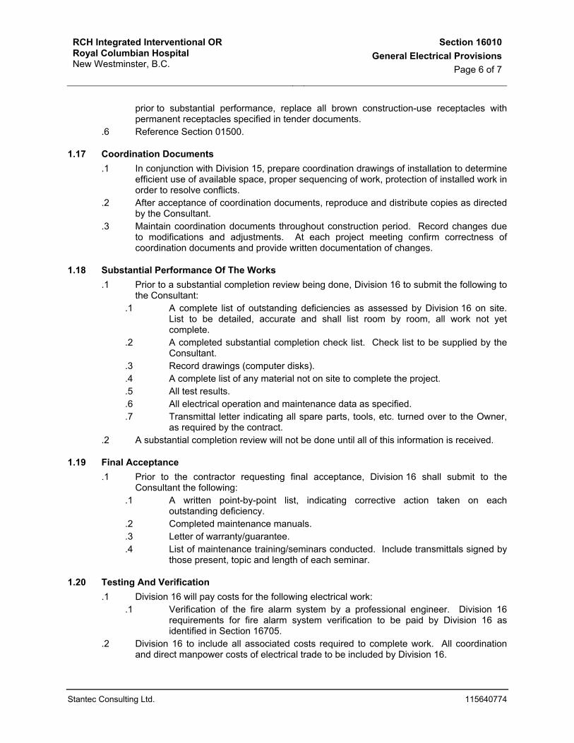
1.17 Coordination Documents .1 In conjunction with Division 15, prepare coordination drawings of installation to determine
efficient use of available space, proper sequencing of work, protection of installed work in order to resolve conflicts.
.2 After acceptance of coordination documents, reproduce and distribute copies as directed by the Consultant.
.3 Maintain coordination documents throughout construction period. Record changes due to modifications and adjustments. At each project meeting confirm correctness of coordination documents and provide written documentation of changes.
1.18 Substantial Performance Of The Works .1 Prior to a substantial completion review being done, Division 16 to submit the following to
the Consultant: .1 A complete list of outstanding deficiencies as assessed by Division 16 on site.
List to be detailed, accurate and shall list room by room, all work not yet complete.
.2 A completed substantial completion check list. Check list to be supplied by the Consultant.
.3 Record drawings (computer disks).
.4 A complete list of any material not on site to complete the project.
.5 All test results.
.6 All electrical operation and maintenance data as specified.
.7 Transmittal letter indicating all spare parts, tools, etc. turned over to the Owner, as required by the contract.
.2 A substantial completion review will not be done until all of this information is received.
1.19 Final Acceptance .1 Prior to the contractor requesting final acceptance, Division 16 shall submit to the
Consultant the following: .1 A written point-by-point list, indicating corrective action taken on each
outstanding deficiency. .2 Completed maintenance manuals. .3 Letter of warranty/guarantee. .4 List of maintenance training/seminars conducted. Include transmittals signed by
those present, topic and length of each seminar.
1.20 Testing And Verification .1 Division 16 will pay costs for the following electrical work:
.1 Verification of the fire alarm system by a professional engineer. Division 16 requirements for fire alarm system verification to be paid by Division 16 as identified in Section 16705.
.2 Division 16 to include all associated costs required to complete work. All coordination and direct manpower costs of electrical trade to be included by Division 16.

RCH Integrated Interventional OR Royal Columbian Hospital New Westminster, B.C.
Section 16010General Electrical Provisions
Page 7 of 7
Stantec Consulting Ltd. 115640774
.3 Prior to work ensure that affected systems are complete and functional according to the Contract Documents, subsequent changes to the work and manufacturers' recommendations.
.4 Supply necessary tradesman, qualified in compliance with the Certificate of Electrical Workers Regulation, to remove and replace wiring disconnect and reconnect system components and replace where defective.
1.21 Warranty .1 Refer to General Conditions.
END OF SECTION

RCH Integrated Interventional OR Royal Columbian Hospital New Westminster, B.C.
Section 16020Work Included
Page 1 of 2
Stantec Consulting Ltd. 115640774
1 GENERAL
1.1 Intent .1 Provide all labour and materials required to complete work of this Division.
Misinterpretation of any requirements of either drawings or specifications shall not relieve Division 16 of responsibility to complete the work. Where required written confirmation to be obtained from the Consultant prior to submitting tender.
1.2 Setting Out Of Work .1 Division 16 to lay out work, do all necessary levelling and measuring. Figures, full size
and detail drawings to take precedence over scale measurements of drawings. No plea as to action or direction of other than the Consultant will be admitted in justification of any error in construction where departure is made from the drawings, specifications or contract. Division 16 responsible to take his own measurements for work.
.2 Correct work completed contrary to the intent of the drawings and specifications and bear all costs for same. Where intent of the drawings and specifications is not clear, obtain clarification from the Consultant before proceeding with work. Provide prompt installation of work when coordinating with other trades as in advance of concrete pouring or similar work. Provide sleeves and locate them for contractor.
.3 Where equipment supplied by Division 16 must be built-in with work of other trades, supply equipment to be built-in or measurements to allow necessary openings to be left so as not to hold up work.
.4 Division 16 to be responsible for any damage caused by improper location or carrying out of his work.
.5 Make reference to electrical, mechanical, structural and architectural drawings when setting out work. Consult with respective Divisions in setting out locations for conduit runs, luminaires, panel assemblies, etc. so that conflicts are avoided and symmetrical even spacing is maintained.
.6 Layouts shown for mechanical rooms are for estimating purposes only. Coordinate installation of equipment, outlets and equipment with final room equipment layout as established by Division 15.
.7 Where switches, receptacles, fire alarm pullstations, are in the same general location, outlets to be lined up vertically unless otherwise called for by the Consultant.
1.3 Examination Of Site .1 Visit site and thoroughly investigate locations, connections and details of all services and
systems which in any way affect or tie-in with work of these specifications and drawings. .2 No extras will be allowed for work resulting from conditions which would have been
evident upon a thorough examination of the site. .3 Notify Consultant, in writing, of any discrepancies or points of doubt or contention.
1.4 Cutting And Patching .1 Contractor to be responsible for all cutting required for electrical installation. Structural
members not to be cut without the consent of the Consultant. .2 Contractor to be responsible for patching and repairing of surfaces damaged by cutting
for electrical work. .3 Where work by Division 16 damages work of other trades, Division 16 to repair and make
good such damage to the satisfaction of the trade concerned and the Consultant.
RCH Integrated Interventional OR Royal Columbian Hospital New Westminster, B.C.
Section 16020Work Included
Page 2 of 2
Stantec Consulting Ltd. 115640774
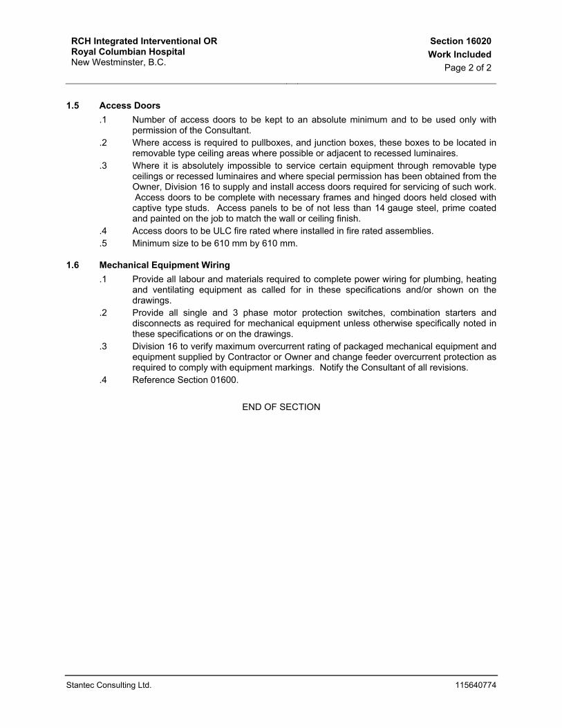
1.5 Access Doors .1 Number of access doors to be kept to an absolute minimum and to be used only with
permission of the Consultant. .2 Where access is required to pullboxes, and junction boxes, these boxes to be located in
removable type ceiling areas where possible or adjacent to recessed luminaires. .3 Where it is absolutely impossible to service certain equipment through removable type
ceilings or recessed luminaires and where special permission has been obtained from the Owner, Division 16 to supply and install access doors required for servicing of such work. Access doors to be complete with necessary frames and hinged doors held closed with captive type studs. Access panels to be of not less than 14 gauge steel, prime coated and painted on the job to match the wall or ceiling finish.
.4 Access doors to be ULC fire rated where installed in fire rated assemblies.
.5 Minimum size to be 610 mm by 610 mm.
1.6 Mechanical Equipment Wiring .1 Provide all labour and materials required to complete power wiring for plumbing, heating
and ventilating equipment as called for in these specifications and/or shown on the drawings.
.2 Provide all single and 3 phase motor protection switches, combination starters and disconnects as required for mechanical equipment unless otherwise specifically noted in these specifications or on the drawings.
.3 Division 16 to verify maximum overcurrent rating of packaged mechanical equipment and equipment supplied by Contractor or Owner and change feeder overcurrent protection as required to comply with equipment markings. Notify the Consultant of all revisions.
.4 Reference Section 01600.
END OF SECTION

RCH Integrated Interventional OR Royal Columbian Hospital New Westminster, B.C.
Section 16021Related Work Specified Elsewhere
Page 1 of 1
Stantec Consulting Ltd. 115640774
1 GENERAL
1.1 Mechanical Equipment Wiring .1 All control conduit and wiring unless specifically noted otherwise for motors and
mechanical equipment will be the responsibility of Division 15. .2 All control components and control connections from control terminal sections of motor
control centres to automatic devices, interlocking, etc. will be the responsibility of Division 15.
.3 Motors for mechanical equipment will be supplied and set in place by Division 15.
.4 Reference Division 15
1.2 Fire Stops .1 The supply and installation of all firestops and smoke seals around electrical equipment,
fittings, etc. will the responsibility of Division 16. Refer to Architectural Specifications for products and installation details.
.2 All wall or channel mounted backboards required for electrical equipment mounting in electrical rooms will be supplied and installed by Division 6. Painting by Division 9.
1.3 Painting .1 All wall or channel mounted backboards required for electrical equipment mounting in
electrical rooms will be supplied and installed by Division 16. Painting by Division 9. .2 Panelboards in finished areas to be factory prime painted ready for site painting by
Division 9
END OF SECTION

RCH Integrated Interventional OR Royal Columbian Hospital New Westminster, B.C.
Section 16025Codes And Fees
Page 1 of 1
Stantec Consulting Ltd. 115640774
1 GENERAL
1.1 Codes, Permits And Inspection .1 The installation is to comply with the requirements of the current edition of the Canadian
Electrical Code, British Columbia Building Code, regulations of the electrical inspection authority and any other Provincial or local by-laws or rules regulating the installation of electrical equipment. Under no circumstances shall the standards established by the contract documents be reduced by any local codes or regulations.
.2 Division 16 to submit appropriate quantity of plans and specifications to the Electrical Inspection Department, obtain all permits required and pay all fees. After completion of the work, furnish to the Consultant a Certificate of Final Inspection and Approval from the electrical inspection authority. Division 16 to take out all permits at the beginning of the work.
.3 Arrange for inspection (attendance during verification) of the work by all applicable authorities having jurisdiction. Include all costs in tender price.
END OF SECTION

RCH Integrated Interventional OR Royal Columbian Hospital New Westminster, B.C.
Section 16031Operation And Maintenance Manuals
Page 1 of 2
Stantec Consulting Ltd. 115640774
1 GENERAL
1.1 Related Work
.1 Coordinate with Division 1.
1.2 Scope
.1 Electrical operations and maintenance manuals (hereinafter referred to as O&M manuals) shall be prepared by Division 16.
.2 Division 16 to be responsible for:
.1 The supply and preparation of four sets of O&M manual binders and tabs as specified in the index below and detailed herein.
.2 The preparation of all written system descriptions and schematics (neatly drafted) as specified below. Format as directed by the Consultant, utilizing proportional typewritten format, with schematics in appendices at the end of each section.
.3 Securing and assembling all necessary literature describing operational and maintenance procedures for all equipment into the O&M manual binders, including Preventative Maintenance data as described below.
.4 Preparing in coordination with Division 16 and equipment manufacturer's technical specialist, scheduled maintenance sheets and check lists. Scheduled maintenance sheets shall include safety in maintenance data plus detailed daily, monthly and yearly scheduled maintenance information. Format as directed by the Consultant.
.5 Preparation of safety in maintenance suggestions and procedures.
.6 Summarized daily, monthly and yearly maintenance charts with checklist sheets.
.7 Prestonia No.2047-10 plastic sheet protectors for all drawings larger than 210 mm by 275 mm. Locate drawing title block on lower right hand corner.
.3 Division 16 shall be responsible for:
.1 Supplying four (4) copies of all information as described below:
.1 Final shop drawings.
.2 Details of design elements, construction features, component function and maintenance requirements, to permit effective operation, maintenance, repair, modification, extension and expansion of any portion or feature of installation.
.3 Technical data, product data, supplemented by bulletins, component illustrations, exploded views, technical descriptions of items, and parts lists. Advertising or sales literature not acceptable.
.4 All wiring diagrams.
.5 List of all major trades, subtrades and suppliers including names of equipment supplied and by whom, addresses, phone numbers, facsimile numbers and contact persons.
.6 Obtaining all data necessary to compile a complete comprehensive Preventative Maintenance program. Data gathered shall be neatly hand-

RCH Integrated Interventional OR Royal Columbian Hospital New Westminster, B.C.
Section 16031Operation And Maintenance Manuals
Page 2 of 2
Stantec Consulting Ltd. 115640774
written on forms provided by the Owner. Data to be collected for all systems described in the index below.
.7 Spare/replacement parts lists for all of the above. Copies of the Division 16 data collection sheets available during tendering period when requested.
.8 Test results as outlined in other sections of this specification.
1.3 Operations And Maintenance Manual Format
.1 Division 16 to submit one copy for Consultant Review prior to completion and submission of all final sets..
.2 Division 16 to provide four (4) complete sets of electrical O&M manuals. Three(3) copies to be turned over to the Owner and one copy to be retained by Consultant.
.3 Electrical O&M manuals to be assembled in 210 mm x 275 mm capacity, expanding spine catalogue binders complete with plated piano hinges, bound in heavy blue fabric, hot stamped gold lettering on front and spine. Division 16 to provide sufficient quantity to allow all binders to hold system data while in full closed position (not expanded).
.4 Division 16 to provide sample of art work and fabric cover (before having binders constructed) to the Consultant.
.1 Include in the manual the following major sections:
.1 Title page (in plastic cover).
.2 Comprehensive description of the operation of the systems, including the function of each item of equipment within the system. Descriptions are to be specific to the work under this project.
.3 Detailed instructions for the normal maintenance of all systems and equipment installed including procedures and frequency of operational checks and service and trouble shooting instructions. Provide summarized procedures for routine work required on all systems.
.4 Local source of supply for each item of equipment.
.5 Wiring and control diagrams.
.6 Spare parts list.
.7 Copies of guarantees and certificates.
.8 Manufacturer's maintenance brochures and shop drawings.
END OF SECTION

RCH Integrated Interventional OR Royal Columbian Hospital New Westminster, B.C.
Section 16032Demonstration And Instruction Sessions
For Electrical Equipment And SystemsPage 1 of 1
Stantec Consulting Ltd. 115640774
1 GENERAL
.1 Division 16 to provide demonstration and instruction sessions to familiarize Hospital operation and maintenance personnel with electrical systems and maintenance. Division 16 to arrange and pay for appropriately qualified manufacturer’s representatives to provide or assist in providing electrical equipment and systems demonstration and instruction.
.2 Section 16031 O & M Manuals to be complete and accepted prior to the demonstration. The manuals to be referred to during the demonstrations.
END OF SECTION

RCH Integrated Interventional OR Royal Columbian Hospital New Westminster, B.C.
Section 16033Electrical Spare Parts & Maintenance
MaterialsPage 1 of 1
Stantec Consulting Ltd. 115640774
1 GENERAL
1.1 Related Work .1 Spare parts and maintenance material - Division 1.
1.2 General .1 Provide a complete inventory of electrical spare parts and maintenance materials as
specified.
1.3 Spare Parts And Maintenance Materials Schedule
Item Quantity .1 Luminaire Ballasts:
.1 Fluorescent Ballasts
4 Of Each Type
.2 Lamps:
.1 Fluorescent Lamps .2 Compact fluorescent
(Incandescent) Lamps
No Less Than 10% Of Each Size And Type No Less Than 15% Of Each Size And Type
* Percentage Of Total Quantity (Minimum Spare Part Quantity Of 2)
.3 Fire Alarm System: .1 Smoke Detectors
2
.4 Communications Cabling System: .1 See Section 16743
END OF SECTION

RCH Integrated Interventional OR Royal Columbian Hospital New Westminster, B.C.
Section 16040Identification
Page 1 of 5
Stantec Consulting Ltd. 115640774
1 GENERAL
1.1 Painting And Finishes .1 All electrical fittings, supports, hanger rods, pullboxes, channel frames, conduit racks,
outlet boxes, brackets, clamps, etc. To have galvanized finish or enamel paint finish over corrosion resistant primer.
.2 All panelboards, distribution centres, motor control centres, transformers, etc. To be factory finished in alkyd high gloss standard ASA grey enamel applied over corrosion resistant primer. Matte or flat type finish paint not acceptable. Except flush panelboards in finished areas to be primed only ready for site paint application by division 9. Factory finished units that are scratched or marked during installation or shipping to be touched up with matching spray-on air dry lacquer or, if required to provide a satisfactory job, completely refinished.
.3 All 347/600 volt pullboxes and raceways to be finished in sand. All emergency 347/600 volt pullboxes and raceways to be finished in sand with a 50mm red paint stripe.
.4 All 120/208 volt pullboxes and raceways to be finished in grey. All emergency 120/208 volt pullboxes and raceways to be finished in grey with a 50mm red paint stripe
.5 Transformer enclosures to be finished in accordance with primary voltage colour as outlined above.
.6 Fire alarm pullboxes and junction boxes to be finished in red.
.7 Telephone terminal panels and junction boxes to be finished in light blue.
.8 Sound and intercommunication terminal panels and junction boxes to be finished in yellow.
.9 Code blue call system terminal panels and junction boxes to be finished in brown.
.10 Clock and timing system terminal panels and junction boxes to be finished in light green.
.11 RF television and in-house television system pullboxes and junction boxes to be finished in dark green.
.12 Low voltage switching terminal cabinets and pullboxes to be finished in black enamel.
.13 Security monitor system pullboxes and junction boxes to be finished in rust.
.14 Security television system pullboxes and junction boxes to be finished in gold.
.15 Miscellaneous (future) system pullboxes and junction boxes to be finished in pink.
1.2 Nametags .1 Clearly identify main distribution centre, subdistribution panels, power panels, lighting
panels, disconnect switches, starters, contactors, motor control centres, terminal cabinets, junction boxes, On/Off switches and transformers by permanent labels described below.
.2 Nametags to be of 3-layer laminated plastic, colour/white/colour with etched lettering giving white letters on coloured background where called for on the drawings or in the specifications. Letters on nametags to be 9 mm high minimum. 25 mm high letters to be used where outlined. Mechanical fastening using drive rivets (not screws) to be used throughout. Lamicoids to have the following base colours:
Blue – Normal Power Red – Emergency Power Black – Switchable Power

RCH Integrated Interventional OR Royal Columbian Hospital New Westminster, B.C.
Section 16040Identification
Page 2 of 5
Stantec Consulting Ltd. 115640774
.3 In terminal cabinets for control wiring, low voltage relays, television distribution, nurses call, sound, telephone, fire alarm, clock, etc. identify terminal strips, etc. utilizing 9 mm roll adhesive back embossed type nametags.
.4 Panels - provide nametags on all panels. Nametags to include panel designators as shown on the drawings as well as the voltage/phase identification. Nametags to be attached to outside of panel door.
.5 Transformers: identify as shown on drawings, showing capacity, primary and secondary voltages.
.6 Disconnect switches, starters and contactors: indicate equipment being controlled and voltage.
.7 Terminal cabinets and pullboxes: indicate system and voltage.
.8 On/Off switches: indicate areas being served.
.9 Distribution centres: identify distribution centres as indicated on drawings and main voltage or voltages if more than one.
.10 Motor control centres: identify as shown on drawings and show main voltage or voltages if more than one.
.11 Labels: .1 Identify each outlet and switch plate, starter, disconnect and all items of fixed
equipment with the appropriate panel and circuit number origin by means of a small but good quality vinyl, self-laminating label as T & B E-Z Code WSL or ‘Brother’ equivalent printable markers. Confirm location of labels with Consultant before installing. Circuit number to agree with Record drawings.
.2 In addition to the plate identification, provide circuit number identification on each actual receptacle in the space provided between the two outlets of the duplex.
.12 All standard power duplex receptacles not adjacent to beds in patient examination and treatment rooms to be labelled "Housekeeping".
.13 Provide plastic covered panel directory with circuits and areas served typed in, and mounted on inside of door. Directory to conform with Record Drawings. In addition indicate the conduit, feeder, breaker size and source on the directory.
.14 Fire alarm end-of-line resistors and duct detectors: Identify zone numbers with 6 mm white lettering on red background on lamicoid nametag located on wall above device.
.15 Fire alarm monitor/control modules, etc.: identify address and device monitored or controlled.
1.3 Conduit Identification .1 All conduit for electrical systems to be colour coded within 200 mm of panel locations,
pullbox locations, within 200 mm of where they enter or leave a room or non-accessible ceiling space, and 5 m on centre within an area. Colour coding of conduit to consist of paint applied so as to provide easy identification, to satisfaction of the Consultant.
.2 Emergency service conduits to be marked with 100 mm wide colour bands, 25 mm lettering every 10m on centre.
.3 Colour coding to be as follows:

RCH Integrated Interventional OR Royal Columbian Hospital New Westminster, B.C.
Section 16040Identification
Page 3 of 5
Stantec Consulting Ltd. 115640774
System Major Colour Minor Color Letter 347/600 Vital Dark Blue Red CCT#
347/600 Delayed Vital Dark Blue Dark Blue CCT# 347/600 Conditional Dark Blue Yellow CCT#
277/480 Vital Yellow Dark Blue/Red CCT# 277/480 Delayed Vital Yellow Dark Blue CCT# 277/480 Conditional Yellow Dark Blue / Yellow CCT#
120/208 Vital Yellow Purple/Red CCT# 120/208 Delayed Vital Yellow Purple/Dark Blue CCT# 120/208 Conditional Yellow Purple/Yellow CCT#
347/600 UPS Light Blue White UPS 120/208 UPS Light Blue Green UPS
Fire Alarm System Red FA Telecom Green TEL Security Green SEC
Door Intercom Green DIS CCTV Green CCTV
Building Automation Green BAS Computer Green C
1.4 Box Identification .1 Above Removable Ceilings: in areas where pullboxes, junction boxes, and/or cabinets
are located above removable ceilings, finish to be in colour specified both on outside and inside. Coverplates to be painted on both sides in the colour specified. Provide panel and circuit numbers or appropriate low tension system identification on coverplate with 12 mm letters.
.2 Non-removable Ceilings: where pullboxes, junction boxes, and/or cabinets are located on or in non-removable ceilings, the interior only shall be finished in the colour specified. Interior faces of coverplates to be painted to match box interior finish.
1.5 Colour Coding Of Conductors .1 Wire identification materials: use one of the following:
.1 Heat shrink sleeves, blank.
.2 Clear plastic tape wrap-on strips with white writing section and black acid pen.
.3 Wrap-on strips, pre-numbered.
.4 Slip-on identification bead markers or sleeves, blank or pre-numbered. .2 Conductors to be colour coded throughout the building with the same colour applying to
the same phase throughout. Colour coding to be by insulation colour or permanently applied colour banding at all distribution centres and panels. Colour coding to be as follows: Equipment grounding conductor: green. Neutral conductor: white. 120/208 volt phase wires: red, black and blue.

RCH Integrated Interventional OR Royal Columbian Hospital New Westminster, B.C.
Section 16040Identification
Page 4 of 5
Stantec Consulting Ltd. 115640774
120/208 volt emergency phase wires: red, black and blue with bead-marker indicating voltage and emergency. 347/600 volt phase wires: orange, brown and yellow. 347/600 volt emergency phase wires: orange, brown, and yellow with bead marker indicating voltage and emergency.
.3 At all distribution centres, pullboxes, wireways, etc., feeder conductors of each feeder group to be neatly laced or clipped into a feeder group with each conductor identified as to load fed. At all pullboxes, junction boxes and device outlet box locations identify each conductor as to panel and circuit, i.e. panel 2a circuit 23 - identify 2a-23. Similar to system proposed for power, conductor identification to be provided for all systems at all pullbox, junction box and device locations.
.4 Identify each conductor as to panel and circuit, terminal, terminal numbers, system number scheme, and polarization as applicable.
.5 All conductors for fire alarm system to be colour coded with separate colour used for each of the following systems, smoke detector box circuits; trouble circuits; auxiliary control circuits; gong circuits, etc. Provide bead markers identifying zones at each device location, junction box, annunciators and panels.
.6 Lamicoid nameplates: 3 mm thick plastic engraving sheet, black face, white core, mechanically attached, sizes as follows:
.1 Size 1: 12 mm high with 5 mm high letters.
.2 Size 2: 20 mm high with 8 mm high letters.
.3 Size 3: 25 mm high with 12 mm high letters.

RCH Integrated Interventional OR Royal Columbian Hospital New Westminster, B.C.
Section 16040Identification
Page 5 of 5
Stantec Consulting Ltd. 115640774
1.6 Equipment Identification Schedule .1 Wire identification materials: use one of the following:
Nameplate Nameplate Lamicoid Equipment Colour Identification Size Distribution Voltage - Distribution Centre Designation, Amperage, And Voltage 2 Centres Colour - Loads Controlled By Each Overcurrent Protective Device 1 Panelboards Voltage - Panelboard Designation 2 Colour - Voltage, Number Of Phases Motor Voltage - M.C.C. Designation, Amperage And Voltage 2 Control Colour - Motors Or Loads Controlled 1 Centre By Each Unit And Mnemonics - Relay Terminal And Transformer Compartments 1 Manual Motor Starters N/A - Load Controlled And Mnemonics, Panel & Circuit Number1 Ground Bus N/A - System Ground 1 On/Off Switches N/A - Load Controlled 1 Disconnect Switches, Voltage Colour - Voltage And Equipment 2 Magnetic Motor Controlled And Mnemonics Starters And Contactors: Transformers Voltage Colour - Transformer Designation, 2 Capacity, Secondary And Primary Voltages Emergency Power Equipment Voltage Colour - Designation And Voltage 2 Wireways N/A - Voltage And System Designation 2 Line Voltage Voltage Colour - Designation And Voltage 2 Cabinets And Enclosures Low Voltage System - System Name; System Name And Number If 2 Cabinets And Colour More Than One Cabinet Or Enclosure Enclosures - Major Components Within Cabinets And Enclosures 1
END OF SECTION

RCH Integrated Interventional OR Royal Columbian Hospital New Westminster, B.C.
Section 16045Seismic Restraints
Page 1 of 4
Stantec Consulting Ltd. 115640774
1 GENERAL
1.1 Related Work .1 This section of the specification forms part of the contract documents and is to be read,
interpreted and coordinated with all other parts.
1.2 Regulatory Requirements .1 Restraints shall meet the requirements of the British Columbia Building code.
1.3 Seismic Restraint Design And Inspection .1 Division 16 is required to provide the services of a registered BC Professional Structural
Engineer who specializes in the restraint of building elements. This structural engineer, herein referred to as the seismic engineer shall provide all required engineering services related to seismic restraints and anchorage for all equipment and services.
.2 The seismic engineer shall provide assistance to the contractor as necessary during the course of restraint of equipment.
.3 The seismic engineer shall inspect the completed seismic installation and shall submit a statutory declaration to the consultant stating that the complete seismic installation is installed in accordance with his drawings and instructions and it complies with the regulatory requirements. Form EF001 in Section 16045 should be used for this purpose.
1.4 Scope Of Work .1 All equipment shall be tested in an independent testing laboratory or shall be certified by
a registered professional engineer to demonstrate that the equipment meets the requirements of all codes and bylaws in terms of "withstanding" the lateral forces in any direction to be expected in the project seismic zone. "withstanding" shall generally mean remaining in one piece and not breaking away from moorings.
.2 Provide certified professionally sealed shop and placement drawings for all electrical equipment and equipment assemblies including runs of conduit/cable racks showing the methods of attachment to the particular structure for each piece of equipment and assembly and provide anchorage/attachment details approved and sealed by a BC registered professional engineer for review by the project structural engineer. Submit samples of materials required to complete the seismic restraint work for review if and when requested. Reports to the consultant throughout construction and to provide as required by the authorities having jurisdiction all required "letters of assurance and conformance" with the specified codes, standards and bylaws. If requested by the consultant, calculations sealed by a professional engineer registered in BC shall be provided for the seismic restraint design shown on the shop drawings. Shop drawings shall show the equipment type, manufacturer's name, model number and weight of the equipment restrained.
.3 Free-standing equipment shall be fastened to the basic structure using anchorage / attachments to overcome seismic overturning forces as designed by a professional engineer as noted above.
.4 Provide slack cable restraint systems as designed by a professional engineer as described previously but generally as follows:

RCH Integrated Interventional OR Royal Columbian Hospital New Westminster, B.C.
Section 16045Seismic Restraints
Page 2 of 4
Stantec Consulting Ltd. 115640774
.1 Connect slack cable restraints to suspended equipment in such a way that the axial projection of the wires passes through the centre of gravity of the equipment.
.2 Oriented restraint wires on suspended equipment at approximately 90° to each other (in plan), and tie back to the structure at an angle not exceeding 45° to the horizontal.
.3 Select each anchor in the structure for a load equal to twice the weight of the equipment with a safety factor of four.
.4 Install cable using appropriate grommets, shackles, thimbles, u-bolts, and other hardware to ensure alignment of the restraints and to avoid bending cables at connection points.
.5 Restraints shall be serviced at least 50 mm clear of all other equipment and services.
.6 Adjust restraint cables such that they are not visibly slack, but such that the flexibility is approximately 35 mm under thumb pressure for a 1500 mm cable length (equivalent ratio for other cable lengths).
.7 Provide transverse and axial restraints within four metres of a vertical bend.
.8 Trapeze hangers for cables, cable trays and raceways shall be restrained utilizing a minimum of 10 mm diameter slack cable restraints which shall be provided at a maximum transverse spacing of 12.5 m and longitudinal restraints at 25 m maximum spacing, or as otherwise limited by anchor/slack cable performance. Adjacent spacing of restraints on a run shall vary by approximately 20 percent to avoid coincident resonances.
.9 Transverse bracing for one raceway section may also act as longitudinal bracing for the raceway connected perpendicular to it, provided the bracing is installed within 610 mm of the elbow or junction box. Branch runs shall not be used to restrain main runs.
.5 Install a 900 mm length of flexible conduit and a braided bonding jumper in each surface mounted conduit where it crosses a building expansion or seismic joint.
.6 Rigid support systems shall not be braced to dissimilar parts of a building or two dissimilar building systems that may respond in a different mode during an earthquake. Provide loops in cables and flexible connections in raceways where such services leave a suspended trapeze rack or other support and extend down to floor braced equipment or wall mounted equipment. Freedom of movement shall be up to 300 mm in all directions.
.7 All recessed lighting luminaires in mechanical grid ceilings (i.e., t-bar) shall be restrained using at least two (2) #16 ASWG stranded stainless steel aircraft cable security bridles per fixture tied to the basic building structure. Attach security bridles at ends of each fixture using a further attachment to each corner of the luminaire and in such a manner that the luminaire cannot fall lower than 300 mm beneath the ceiling.
.8 Surface-mounted lighting luminaires mounted on mechanical grid ceilings shall be attached to the ceiling system with positive clamping devices that completely surround the supporting members. Security bridles shall be minimum #16 ASWG stranded stainless steel aircraft cables and attached between the clamping devices and adjacent ceiling hanger or to their structure above in the same manner as described for recessed luminaire supports.

RCH Integrated Interventional OR Royal Columbian Hospital New Westminster, B.C.
Section 16045Seismic Restraints
Page 3 of 4
Stantec Consulting Ltd. 115640774
.9 Pendant-hung or chain-hung lighting luminaires shall be provided with minimum #16 ASWG stranded stainless steel aircraft cables to the structure in the same manner as described for recessed luminaire supports.
.10 Electrical outlet boxes flush mounted in mechanical grid ceilings shall be anchored to ceiling grid.

RCH Integrated Interventional OR Royal Columbian Hospital New Westminster, B.C.
Section 16045Seismic Restraints
Page 4 of 4
Stantec Consulting Ltd. 115640774
11. EF001 CERTIFICATE OF SEISMIC RESTRAINT INSTALLATION
I HEREBY DECLARE THAT I _________________________
AM AN EMPLOYEE / A PRINCIPAL OF _________________________________
AND CERTIFY THAT THE SEISMIC RESTRAINT OF ALL ELECTRICAL EQUIPMENT AND SERVICES SPECIFIED UNDER DIVISION 16 HAS BEEN SATISFACTORILY COMPLETED AND THAT THE INSTALLATION MEETS THE REQUIREMENTS OF THE B.C. BUILDING CODE AS IT RELATES TO SEISMIC RESTRAINT.
SIGNED ______________________________ DATE ____________________
NOTES:
1. This Certificate Must Be Submitted When Requesting Inspection Of Substantial Performance.
END OF SECTION

RCH Integrated Interventional OR Royal Columbian Hospital New Westminster, B.C.
Section 16111Conduit
Page 1 of 3
Stantec Consulting Ltd. 115640774
1 GENERAL
1.1 Related Sections .1 Section 16040 – Identification
2 PRODUCTS
2.1 Materials .1 Minimum size of conduit to be 19 mm.
2.2 Metal Conduit And Tubing .1 Rigid Metal Conduit: to CSA C22.2 No. 45-M1981, and as follows:
.1 PVC Externally Coated Rigid Steel Conduit: zinc coated steel with additional external coating of PVC.
.2 Epoxy Coated Rigid Steel Conduit: zinc coated steel with additional epoxy coating inside and outside.
.3 Fittings: same material as conduit. .2 Electrical Metallic Tubing (EMT): to CSA C22.2 No. 83-M1985, with fittings as follows:
.1 Fitting Material for 25 mm size Conduit and Smaller: zinc alloy or zinc coated steel.
.2 Fitting Material for Conduit Larger than 25 mm size: zinc coated steel.
.3 Type: compression or set screw, liquid tight for wet or damp areas. .3 Flexible metal Conduit: to CSA C22.2 No. 56-1977, and as follows:
.1 Liquid-Tight Flexible Metal Conduit: continuous interlocked and double-wrapped steel, zinc coated inside and outside, coated with liquid-tight jacket of flexible PVC, minimum 19 mm diameter.
.2 Liquid-Tight Flexible Metal Conduit Fittings: cadmium plated, malleable iron fittings with compression type steel ferrule and neoprene gasket sealing rings.
2.3 Non-Metallic Conduit .1 Rigid Type EB1 PVC Conduit: CSA C22.2 No. 211.1-M1984. .2 Rigid type DB2/ES2 PVC Conduit: CSA C22.2 No. 211.1-M1984. .3 Rigid PVC Conduit Schedule 40: CSA C22.2 No.136
Fittings: CSA C22.2 No. 85
3 EXECUTION
3.1 Installation .1 All wiring to be installed in conduit except voice and data which will be installed in conduit
and/or cabletray. .2 Conduit penetrations through concrete floors, etc. To be sleeved or poured in place. Do
not core. .3 Electrical metallic tubing may be utilized in poured concrete walls or block walls filled with
concrete provided that all stubups through floors or walls are of rigid threaded galvanized steel. Electrical metallic tubing may be utilized for all exposed runs with the exception of those installed 2100 mm from floor level or where subject to mechanical injury in

RCH Integrated Interventional OR Royal Columbian Hospital New Westminster, B.C.
Section 16111Conduit
Page 2 of 3
Stantec Consulting Ltd. 115640774
accordance with code, which are to be rigid steel. Protective steel covers are not permitted.
.4 Install conduit concealed in all areas except tunnels, mechanical and electrical rooms, where it may be installed exposed. All conduit to be installed parallel to, or at right angles to building lines.
.5 Flexible conduit to be installed from ceiling outlet box to tee bar mounted luminaires. All ground conductors to be sized for appropriate bx or flexible conduit size. Provide surplus flexible conduit connection to each ceiling luminaire to allow future relocation of luminaire 1 m in any direction without rewiring.
.6 Do not install conduit in structural floor slabs. (ie. main floor, level 1, level 2, level 3). (No exceptions).
.7 Conduit not to be installed in poured-in-place concrete slabs.
.8 Rigid galvanized steel conduit shall be used where installed through grade beams, foundation walls and for all stubouts and luminaire bases. In all cases rigid galvanized steel sections to be not less than 3 m in length, terminating not less than 2 m from concrete base or wall surface.
.9 Install conduit free from dents and bruises and plug ends to prevent entrance of dirt or moisture. Clean out conduit for installation of conductors.
.10 Coordinate installation of conduit in brick or block walls with masonry trade to allow mason to thread brick or blocks over conduit.
.11 Install sealtite flexible conduit connections to all motors from conduit stubups and from junction boxes to avoid transmission of vibration from machinery to building structure.
.12 Install conduit to avoid interference with other trades and to maintain maximum headroom.
.13 Junction boxes when used, to be installed in areas that are accessible through luminaire openings and/or access panels.
.14 Seal conduit with approved duct seal or fibreglass where conduits leave heated area and enter unheated area.
.15 Provide necessary flashing and pitchpockets to make watertight joint where conduits pass through roof.
.16 Utilize approved expansion fittings complete with grounding jumper where conduit installed crosses building expansion lines. Install feeder runs of conduit in suspended ceiling spaces in such a manner that there is a bend or off-set adjacent to the major building expansion line to take up building movement. In lieu of this, utilize approved expansion fitting.
.17 Conduit installed in ceiling spaces to be mounted on conduit racks. Conduit racks to be coordinated with mechanical ducting and the specific rack configuration to be approved by the consultant prior to installation. Conduit racks to be sized and configured to provide space for not less than six 25 mm conduits or at least 25% future capacity, whichever is greater.
.18 Openings for conduit penetrations in fire rated and smoke separations to be sealed using materials approved by the consultant. All blockouts and access slots to be sealed using sealant as outlined in general specifications. Install using fire approved damming material as required to provide designated fire ratings.
.19 Empty conduit to be cleaned, swabbed and provided with #22 gauge galvanized metal pullwire. Pull string should be allowed.
.20 Existing conduit that is affected by this project construction to be extended, replaced, rerouted or removed as dictated by jobsite conditions.
.21 Conduit for site lighting and receptacles is drawn diagrammatically. Division 16 to route conduit in an orderly manner but in all cases shall maintain a minimum of 3.0m clearance

RCH Integrated Interventional OR Royal Columbian Hospital New Westminster, B.C.
Section 16111Conduit
Page 3 of 3
Stantec Consulting Ltd. 115640774
from existing vegetation or new proposed vegetation as indicated on landscape drawings. Conduit routing and location to be carefully documented on the “as built drawings”.
.22 Minimum conduit size 19mm for communication. Use minimum 25mm conduit for wiring serving more than one outlet.
.23 13mm conduit acceptable for single branch power subcircuits. All home runs to be minimum 19mm.
.24 All conduit to be installed vertical in walls preferably from the ceilings. Horizontal conduits not acceptable except close nippled boxes.
3.2 Conduit Installation Schedule .1 Install conduit as indicated except where otherwise required by Canadian Electrical
Code. TYPE LOCATION .1 Galvanized Rigid Steel .1 Conduit stubouts through concrete grade
beams and conduit stubouts from luminaire bases.
.2 Exposed conduit stubups.
.3 Areas subject to mechanical damage. .2 Liquid-tight flexible steel conduit. .1 Motor connections.
.2 Damp locations.
.3 Mechanical Rooms.
.4 Fire alarm sprinkler devices.
.5 Transformer connections. .3 Flexible steel conduit .1 Luminaire connections.
.2 Control device connections
.3 Low tension device connection in acoustical grid ceilings.
.4 Maximum length 3 mm from outlet box to end device at any location.
.4 EMT (Electrical Metallic Tubing) .1 All other locations.
END OF SECTION

RCH Integrated Interventional OR Royal Columbian Hospital New Westminster, B.C.
Section 16116Surface Raceways And Fittings
Page 1 of 1
Stantec Consulting Ltd. 115640774
1 GENERAL
1.1 Related Sections .1 Section 16040 – Identification .2 Section 16152 - Supporting Devices
2 PRODUCTS
2.1 Components .1 Surface raceways: to consist of an assembly of backing and capping made of metal
suitable coated or non-metallic, to be corrosion-resistant, and have an interior finish designed to avoid abrasion of the electrical conductors which it contains. Surface raceways to be one piece or two piece. Surface raceways required under this contract to be three-compartment plugmold series or approved equivalent with two (2) dividers for:
.1 Normal power
.2 Emergency power
.3 Telephone/data systems .2 Raceway systems to be complete in all cases with necessary corners, boxes, adaptors,
etc. As required to provide a complete continuous installation in all cases.
3 EXECUTION
3.1 Installation .1 Install surface raceways on walls or millwork as indicated on the drawings. Provide all
mounting hardware necessary for installation. All surface raceways to be supported on not greater than 900 mm on centre.
.2 Where conduit or box adaptation is used provide necessary adaptors.
.3 Locate all devices within respective compartments. Provide stainless steel plates for all devices.
END OF SECTION

RCH Integrated Interventional OR Royal Columbian Hospital New Westminster, B.C.
Section 16120Wire And Cable
Page 1 of 3
Stantec Consulting Ltd. 115640774
1 GENERAL
1.1 Related Work .1 Section 16040 – Identification
1.2 Regulatory Requirements .1 All branch circuit wiring for receptacles and permanently wired equipment in defined
patient care areas are to be installed in accordance with Section 24 of the Canadian Electrical Code “Patient Care in Hospitals” and CSA Z32-99 to ensure installation compliance.
2 PRODUCTS
2.1 Materials .1 All interior building wiring to be 98% conductivity copper, with 600 volt RW90 X-link
insulation unless specified below. Aluminium conductors permitted for feeder conductors larger than 3/0 copper. All conductor sizes indicated on drawings are based on copper conductors.
.2 Branch Circuit Wiring: conductors smaller than #12 AWG not permitted for lighting, power or motor branch circuits.
.3 #10 AWG RW90 X-link conductors to be used for 347 volt site lighting circuits and No.12 AWG RW90 for lighting controls.
.4 Refer to Section 16705 for fire alarm system wiring.
.5 Refer to Section 16700 for communications systems wiring.
.6 BX type wiring may only be utilized for recessed tee bar luminaire drops from ceiling mounted outlet boxes.
.7 TBS90 #14 AWG stranded shall be used in all switchgear assemblies. Current transformer secondary wiring shall be #12 AWG stranded. Current transformer leads shall incorporate ring type tongues for termination purposes.
.8 Feeder wiring up to 750 volts may be PVC jacketted armoured cable, multi-copper conductor type Teck or ACWU90 1000 volt having a PVC jacket with FT-4 flame spread rating suitable for installation in air plenums. Armoured cable to be used only where specifically indicated on the drawings or in the specifications.
.9 Ground wires shall be Class B stranded bare copper conductors of sizes indicated and required by the Canadian Electrical Code.
3 EXECUTION
3.1 Installation .1 Conductor length for parallel feeders to be identical. Provide permanent plastic nametag
indicating load fed. .2 Lace or clip groups of feeder conductors at all distribution centres, pullboxes, and
termination points. .3 All grounding conductors and straps to be copper. All bonding conductors to have green
insulation jacket. .4 Colour coding to be strictly in accordance with Section 16040.

RCH Integrated Interventional OR Royal Columbian Hospital New Westminster, B.C.
Section 16120Wire And Cable
Page 2 of 3
Stantec Consulting Ltd. 115640774
.5 Each conductor is to be identified at each end where they are spliced or terminated in a pullbox, panel, fitting, or device. Conductors that pass through a pullbox are to be identified in that box. The identification tag shall show the panel designation and circuit number or wire number on each conductor. Information shall be printed in legible form. Neutral conductor is to be tagged with the circuit numbers that is serves. Switched conductors are to be tagged with “SW” after circuit identification.
.6 Wiring colour code as follows: .1 120 / 208 Volt system phase wires red, black and blue. .2 347 600 Volt system phase wires orange, brown, and yellow.
.7 Colour coding of phase conductors: .1 Number 10 conductors and smaller: shall be red, black, blue, orange, brown,
yellow, white as required. .2 Number 8 to 3 conductors shall be red, black blue, white for 120 / 208 Volt
systems. Colour banding is acceptable on the red, black, and blue conductors for the orange, brown yellow identification of the 347 / 600 Volt systems.
.3 Larger than Number 3 can be black with appropriate colour banding. .8 The number of conductors combined in a homerun not to exceed that shown on the
drawings. .9 Megger tests and resistance to ground tests to be performed on all feeders prior to
energization. .10 All branch circuit wiring for receptacles and permanently wired equipment in intermediate
and critical care areas to be 2-wire circuits only, i.e. common neutrals not allowed. Common neutrals may be used in general care areas. Refer to Canadian Electrical Code, Section 24, Patient Care Areas in Hospitals. Both normal power and emergency power receptacles servicing intermediate and critical patient care areas to be connected to barriered equipotential grounding cabinet. Barriered cabinet to contain two separate ground busses bonded together. The patient care areas are divided into three classifications and have been defined as follows:
.1 General Care .1 Patient Examination Room
.2 Intermediate Care .1 Nursery .2 LBRP Patient Beds .3 Isolation Ante .4 Isolation LBRP .5 Ante Partum
.3 Critical Care .1 C Section / Operating Room .2 Resuscitation .3 Intensive Care Neonatal Unit
.11 A #10 AWG ground conductor to be installed in all conduits containing branch circuit wiring for receptacles and permanently wired equipment in all general, intermediate and critical care areas. #10 AWG ground conductor to be part of equipotential grounding system as specified in Section 16160 in intermediate and critical care areas.
RCH Integrated Interventional OR Royal Columbian Hospital New Westminster, B.C.
Section 16120Wire And Cable
Page 3 of 3
Stantec Consulting Ltd. 115640774
.12 All branch circuit wiring for surge suppression receptacles and permanently wired computer and electronic equipment to be 2-wire circuits only, i.e. common neutrals not permitted.
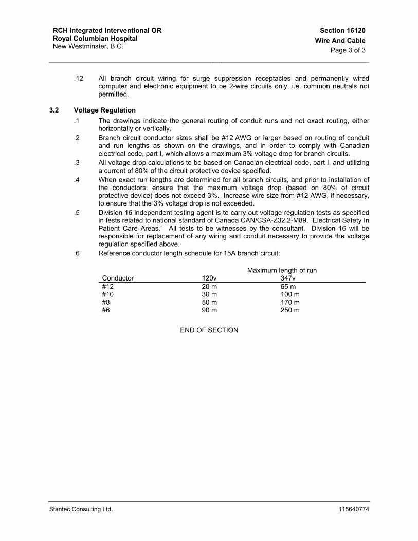
3.2 Voltage Regulation .1 The drawings indicate the general routing of conduit runs and not exact routing, either
horizontally or vertically. .2 Branch circuit conductor sizes shall be #12 AWG or larger based on routing of conduit
and run lengths as shown on the drawings, and in order to comply with Canadian electrical code, part I, which allows a maximum 3% voltage drop for branch circuits.
.3 All voltage drop calculations to be based on Canadian electrical code, part I, and utilizing a current of 80% of the circuit protective device specified.
.4 When exact run lengths are determined for all branch circuits, and prior to installation of the conductors, ensure that the maximum voltage drop (based on 80% of circuit protective device) does not exceed 3%. Increase wire size from #12 AWG, if necessary, to ensure that the 3% voltage drop is not exceeded.
.5 Division 16 independent testing agent is to carry out voltage regulation tests as specified in tests related to national standard of Canada CAN/CSA-Z32.2-M89, “Electrical Safety In Patient Care Areas.” All tests to be witnesses by the consultant. Division 16 will be responsible for replacement of any wiring and conduit necessary to provide the voltage regulation specified above.
.6 Reference conductor length schedule for 15A branch circuit:
Maximum length of run Conductor 120v 347v #12 20 m 65 m #10 30 m 100 m #8 50 m 170 m #6 90 m 250 m
END OF SECTION

RCH Integrated Interventional OR Royal Columbian Hospital New Westminster, B.C.
Section 16130Outlet Boxes
Page 1 of 2
Stantec Consulting Ltd. 115640774
1 GENERAL
1.1 Related Sections .1 Section 16010 - General Electrical Provisions .2 Section 16120 - Work Included
1.2 Quality Assurance .1 Boxes: hot dip galvanized, conforming to CSA requirements.
2 PRODUCTS
2.1 Materials .1 Interior boxes: galvanized pressed sheet steel boxes, blanked for conduit, attached lugs
for locating. .2 Exterior boxes: cast corrosion-resistant deep type boxes.
2.2 Components .1 Boxes for ceiling to be octagon No.54151 or 54171, or square no.52151, 52171 or 72171. .2 Boxes for flush mounting switches, receptacles, low tension, telephone to be No.52151 or
52171 box with matching plaster cover for single or two gang outlets. For larger boxes use GSB solid type as required. For masonry work use MBD type boxes.
.3 Boxes for surface mounted switches, receptacles, communications, telephone to be 100 mm square 52151 or 52171 with Taylor 8300 series covers.
3 EXECUTION
3.1 Installation .1 All outlet boxes to be flush mounted in all areas, excluding mechanical rooms, electrical
rooms, and above removable ceilings. .2 Adjust position of outlets in finished masonry walls to suit masonry course lines.
Coordinate cutting of masonry walls to achieve neat openings for all boxes. All cutting of masonry work for installation of electrical fittings to be done using rotary cutting equipment.
.3 No sectional or handy boxes to be installed.
.4 For outlets mounted in exterior walls provide vapour barrier insulation behind outlet boxes to prevent condensation through boxes.
.5 For outlets mounted above counters, benches, splashbacks, coordinate location and mounting heights with built-in units. Refer to architectural details. Where heating units occur, adjust outlet mounting height to coordinate with same.
.6 Refer to wiring device and communication specification sections and to architectural layouts for mounting heights of outlet boxes.
.7 Backboxes for all communications systems equipment to be provided in accordance with specific manufacturer's recommendations and as specified in the communications sections of these specifications.
.8 Separate outlets located immediately alongside one another to be mounted at exactly the same height above finished floor.

RCH Integrated Interventional OR Royal Columbian Hospital New Westminster, B.C.
Section 16130Outlet Boxes
Page 2 of 2
Stantec Consulting Ltd. 115640774
.9 Where outlet boxes penetrate through a fire separation, ensure that they are tightly fitted with non-combustible material to prevent passage of smoke or flame in the event of a fire.
.10 All outlet boxes for each system to be spray painted with colour as specified in section 16040.
END OF SECTION

RCH Integrated Interventional OR Royal Columbian Hospital New Westminster, B.C.
Section 16131Pull And Junction Boxes
Page 1 of 1
Stantec Consulting Ltd. 115640774
1 GENERAL
1.1 Related Sections .1 Section 16040 – Identification
2 PRODUCTS
2.1 Components .1 Pullboxes and junction boxes: code gauge metal construction, and/or cast corrosion-
resistant type, conforming to Canadian electrical code, with screw-on or hinged cover.
3 EXECUTION
3.1 Installation .1 Provide pullboxes and junction boxes in locations shown on the drawings and as
required to suit job conditions. .2 Locate pullboxes and junction boxes above removable ceilings, in electrical rooms, utility
rooms or storage areas. .3 Where pullboxes are flush mounted, provide overlapping covers with flush head cover
retaining screws, prime coated and painted to match wall or ceiling finish. .4 Where cast corrosion resistant boxes are used, covers to be of matching type and
gasketted. .5 Where pullboxes and/or junction boxes are other than the standard 100 mm square or
octagon box, over and above paint identification for the system provide lamicoid nametags to box covers with 9 mm lettering identifying system.
.6 Interior of all pullboxes and junction boxes for each system to be spray painted with colour as specified in section 16040, identification.
.7 All pullboxes, junction boxes and cabinets to be supported directly from building structure using one or a combination of galvanized screws, galvanized bolts, galvanized rods, and approved box clip.
.8 Support of pullboxes, junction boxes and cabinets by conduit fittings or wire shall not be considered.
.9 Junction boxes, when used, to be installed in areas that are accessible through luminaire openings, and/or access panels.
END OF SECTION

RCH Integrated Interventional OR Royal Columbian Hospital New Westminster, B.C.
Section 16140Switches
Page 1 of 1
Stantec Consulting Ltd. 115640774
1 GENERAL
1.1 Related Sections .1 Section 16040 – Identification .2 Section 16130 - Outlet Boxes
2 PRODUCTS
2.1 Components .1 Line voltage switches: 120 volt, 347 volt, quiet, slow make, slow break design, ivory (red
for switches controlling emergency lighting circuits) toggle handle, with totally enclosed case, rated at 20 Amp, industrial specification grade. Two pole, 3 way and 4 way switches to be of matching type. Switches to be manufactured by Arrowhart, Bryant, Leviton, Hubbell.
.2 Lighted handle switches: Quiet, slow make, slow break design, illuminated ivory toggle handle (neon lamp in ivory toggle handle glows when switch is in "Off" position), with totally enclosed case, rated at 20 Amp, industrial specification grade.
.3 Pilot light switches: Quiet, slow make, slow break design, neon lamp in red toggle handle lights when switch is in "On" position, totally enclosed case, rated at 20 Amp, industrial specification grade.
.4 Lock switches: Quiet, slow make, slow break, key switch with safety block, key with each switch, totally enclosed case, rated at 20 Amp, industrial specification grade.
.5 Timer switches: spring wound, single pole, single throw, breaks circuit at end of timing cycle, 20 Amp, 120 volt, 30 minute time range, without "hold" position, Intermatic or approved equivalent.
3 EXECUTION
3.1 Installation .1 Coordinate switch location with architectural detail and adjust, if required, to coordinate
with panelling, dados, and masonry course lines. .2 All switches to be standard or pilot light as indicated on the drawings. Provide lamicoid
nametag for all switches with pilot lights. Provide red handle for all switches controlling emergency lighting circuits.
.3 Install or wire to and connect all switches required for special equipment that are not prewired by supplier.
.4 Refer to Section 16010 for mounting heights.
.5 Switches for lighting in HVAC plenums to be lighted handle type.
.6 Switch conductors to be tagged with “SW” after circuit identification.
END OF SECTION
RCH Integrated Interventional OR Royal Columbian Hospital New Westminster, B.C.
Section 16142Dimmers
Page 1 of 1
Stantec Consulting Ltd. 115640774
1 GENERAL
1.1 Related Sections .1 Section 16130 - Outlet Boxes
2 PRODUCTS
2.1 Acceptable Products .1 Incandescent dimmers to be Lutron Nova-T series, radio frequency suppression type.
2.2 Components .1 Incandescent dimmers to be CSA approved solid state, semi conductor type for 120 volt,
60 Hz operation, slide control, capable of controlling light intensity over the complete range from "Off" to "Full Brightness" with integral On/Off switch at the low end. Units. to be suitable for flush mounting in 1- or 2-gang outlet box.
.2 Dimmer capacity: 600, 1000, 1500 and 2000 watts.
.3 Dimmer switches: radio frequency suppression type.
3 EXECUTION
3.1 Installation .1 Install dimmer switches where indicated on drawings. No common neutrals to be used
on dimmer circuits. .2 Rating of each individual dimmer to exceed the connected load by not less than 25 per
cent of the connected load.
END OF SECTION

RCH Integrated Interventional OR Royal Columbian Hospital New Westminster, B.C.
Section 16145Receptacles
Page 1 of 3
Stantec Consulting Ltd. 115640774
1 GENERAL
1.1 Related Work .1 Section 16010: General Electrical Provisions .2 Section 16020: Work Included .3 Section 16130: Identification .4 Section 16130: Outlet Boxes .5 Section 16160: Grounding
2 PRODUCTS
2.1 Components .1 All 15 Amp, 125 volt and 20 Amp, 125 volt, single and duplex receptacles to be 2 pole, 3
wire hospital grade, ivory or red, straight blade, impact resistant nylon face, 1-piece grounding system, Bryant 8200/8300-I, Hubbell 8200/8300-I. Note – Quad Receptacles not permitted on this project. All receptacles on normal power to have ivory face. All receptacles on emergency power to have red face. Tamper resistant receptacles shall be 15 amp, 120 volts, Hubbell Cat. No. HBLSG62HI (Ivory) and HBLSG62HR (Red) or approved equivalent.
.2 All 15 Amp, 125 volt surge suppression duplex receptacles to be 2 pole, 3 wire hospital grade, audible alarm type, blue face, straight blade, impact resistant nylon face, Hubbell. Receptacles on emergency to have red face.
.3 Refer to Section 16160 for receptacles connected to equipotential grounding systems.
.4 Ground fault interrupter duplex receptacles to be hospital grade, terminal type to provide individual protection, complete with breaker and reset switch, ivory, parallel blade, U-grounding slot, rated at 15 Amp, 125 volt, Bryant GFR82, Hubbell GF-8200-I.
.5 All special receptacles, locking and non locking type, to be Hubbell or Bryant, nylon face. 20 Amp, single phase, 120 volt, 2 pole, 3 wire, grounding, configuration as per Code Table 46, No.5-20R. 30 Amp, single phase, 120 volt, 2 pole, 3 wire, grounding, configuration as per Code Table 46, No.5-30R. 15 Amp, single phase, 250 volt, 2 pole, 3 wire, grounding, configuration as per Code Table 46, No.6-15R. 20 Amp, single phase, 250 volt, 2 pole, 3 wire, grounding, configuration as per Code Table 46, No.6-20R. 20 Amp, single phase, 250 volt, 3 pole, 4 wire grounding, configuration as per Code Table 46, No.14-20R. 30 Amp, single phase, 250 volt, 2 pole, 3 wire, grounding, configuration as per Code Table 46, No.6-30R (twistlock). 50 Amp, single phase, 250 volt, 2 pole, 3 wire, grounding, configuration as per Code Table 46, No.6-50R (twistlock).
.6 Temporary Construction-Use Receptacles: Commercial grade, 120 volt, 15 amp, 2 pole, 3 wire grounded duplex receptacle, brown in colour with brown coverplate.

RCH Integrated Interventional OR Royal Columbian Hospital New Westminster, B.C.
Section 16145Receptacles
Page 2 of 3
Stantec Consulting Ltd. 115640774
3 EXECUTION
3.1 Installation .1 Mount receptacles vertically and at height specified in Section 16010. Mount receptacles
vertically at 150 mm (to bottom of plate) above counter and open shelves, and centred between shelves in millwork areas unless otherwise noted.
.2 In all service areas, receptacle mounting height to be coordinated with furnishings within the space. In Examination and Procedure Rooms, receptacle locations and mounting heights to be as indicated on detail drawings. Note all receptacles mounted on common walls to be staggered to minimize sound penetration. Where common conduit is used, conduit to be sealed.
.3 Tamper resistant duplex receptacles to be used in all children play areas and in all waiting areas.
.4 Surge suppression duplex receptacles to be provided for all communication and computer terminal equipment backboards and cabinets including fire alarm, telephone, public address, door security, nurse call, central dictation, RF television, security television, etc. Provide dedicated neutral conductors for each surge suppression receptacle.
.5 Ground fault interrupter duplex receptacles to be used in wet locations.
.6 Hospital grade duplex receptacles to be used in all patient care areas.
.7 Provide mechanically fastened (with drive rivets, not screws) lamicoid nametags for all receptacles as noted in Section 16040.
.8 Provide and install temporary construction use receptacles as required and directed by the general contractor up to a maximum of 25% of all interior receptacles. Prior to substantial performance all brown receptacles to be replaced with receptacles intended for that area.
3.2 Identification .1 Receptacles shall have the circuit number and supplying panel board identified at the
outlet. This identification shall be located between the outlets of the receptacle – not on the cover wall.
.2 Labels shall be plastic adhesive tap (similar to “Brother” type labels) color coded to match the receptacle power type as follows:
.1 vital power – red with white text
.2 delayed vital power – blue with white text
.3 conditional power – yellow with black text
.4 UPS – greg with black text
.5 normal power – black with white text. .3 The color coding of the receptacle shall be as follows:
.1 Normal power –white
.2 vital/delayed vital – red
.3 m3 enhanced vital (UPS)- grey .4 Lamacoid as per section 16040

RCH Integrated Interventional OR Royal Columbian Hospital New Westminster, B.C.
Section 16145Receptacles
Page 3 of 3
Stantec Consulting Ltd. 115640774
END OF SECTION

RCH Integrated Interventional OR Royal Columbian Hospital New Westminster, B.C.
Section 16147Plates
Page 1 of 1
Stantec Consulting Ltd. 115640774
1 GENERAL
1.1 Related Work .1 Section 16010: General Electrical Provisions .2 Section 16040: Identification .3 Section 16140: Switches .4 Section 16145: Receptacles .5 Section 16149: Low Voltage Switching
2 PRODUCTS
2.1 Materials .1 Stainless steel: Type 302 or 304, No. 4 finish, 1 mm thick, accurately die cut, protective
release paper complete with tamperproof stainless steel screws. .2 Cast metal: die cast profile, ribbed for strength, flash removed, primed with grey enamel
finish and complete with four mounting screws to box. .3 Gaskets: resilient rubber or close cell foam urethane. .4 Steel: hot dip galvanized to 381 g/m2 minimum.
2.2 Components .1 Nylon cover plates for all receptacles, and smooth face. .2 Metal screws with stainless steel finish. .3 Surface box plates: bevelled, pressure formed for smooth edge free fit to box. .4 Weatherproof Plates: cast metal gasketed coverplates for receptacles, spring loaded
cast gasketed doors. Double doors for standard duplex receptacles. Coverplates to fasten to box by four screws.
.5 Upper edge of plates located on separate outlets immediately alongside one another to be at exactly the same height above finished floor.
.6 All plates to be installed parallel, or perpendicular, to building lines.
2.3 Approved Manufacturer .1 Standard Duplex Receptacle Hubbell #HBL 5205WO .2 GFI receptacles Hubbell #WP26
3 EXECUTION
3.1 Installation .1 Install coverplates on all wiring device boxes. .2 Stainless steel plates shall be used in all areas of the building, including service rooms. .3 Cast weatherproof plates to be used where so indicated on drawings.
END OF SECTION

RCH Integrated Interventional OR Royal Columbian Hospital New Westminster, B.C.
Section 16152Supporting Devices
Page 1 of 1
Stantec Consulting Ltd. 115640774
1 GENERAL
1.1 Related Sections .1 Section 16111 – Conduit
2 PRODUCTS
2.1 Components .1 Conduit Supports: single runs of galvanized conduit straps or ring bolt type hangers.
Multiple runs (three or more) to be rod suspended and surface mounted unistrut channels for conduit rack with 25% spare capacity. Vertical runs to be unistrut channel support with conduit fittings.
.2 Cable Tray Supports: trapeze style hangers with 40 mm x 40 mm galvanized steel channels, supported by 9 mm threaded rod hangers from preset and/or afterset concrete inserts, 2.4 m on centre and at all bends and tee fittings.
3 EXECUTION
3.1 Installation .1 Install to maintain headroom, neat mechanical appearance and to support equipment
loads required. .2 Where inserts are required in concrete, expansion inserts, lead inserts or plastic inserts
may be used in drilled holes. Wood or fibre plugs not permitted. Shot driven pins are not permitted.
.3 Supporting devices to be connected directly to the building structure.
.4 Panelboards and cabinets located in mechanical, electrical and service rooms to be mounted on unistrut channels, 25 mm clear of wall.
.5 Bridge studs top and bottom with channels to support flush mounted cabinets and panelboards in stud walls.
.6 Conduits not to be suspended from suspended acoustic tile ceiling system.
.7 Provide bridge support between steel studs for all outlet boxes larger than two gang.
END OF SECTION

RCH Integrated Interventional OR Royal Columbian Hospital New Westminster, B.C.
Section 16160GroundingPage 1 of 3
Stantec Consulting Ltd. 115640774
1 GENERAL
1.1 Related Work .1 Section 16010: General Electrical Provisions .2 Section 16111: Conduit .3 Section 16120: Wire and Cable .4 Section 16145: Receptacles
1.2 Summary .1 Install complete grounding system as indicated and in accordance with Canadian
Electrical Code and local inspection authority. .2 The products specified in Part 2.0 below are applicable for all grounding systems shown
on the drawings and specifications and as required by Code, and include: .1 Electrical Grounding, .2 Building Grounding,
2 PRODUCT
2.1 Ground Busses .1 Ground busses to be 50 mm x 6 mm copper minimum, mounted on insulating standoffs,
complete with approved ground lugs suitably sized for grounding cables as indicated on the drawings and specifications. Ground bus length to be as indicated on drawings.
.2 Copper or bronze lugs required for termination of all copper conductors at ground busses.
.3 All grounding interconnections at grounding bays to be done by compression connections or thermal weld.
3 EXECUTION
3.1 Circuit Ground Conductors .1 Install grounding bushings, grounding studs and grounding jumpers at all distribution
centres, pullboxes, motor control centres, panelboards where separate grounding conductors are indicated or required.
.2 Bonding Jumpers: green insulation, sized by Code Table 16, sized for over-current device protecting the circuit. Connect to grounding bushings on conduit, to lugs on boxes, tubs and other enclosures. Connection to neutral made only at service neutral bar to separate lug and at secondary of distribution transformer.
.3 Install bonding wire as required by Code in all flexible conduit connected at each end to a grounding bushing, solderless lug, clamp, cup washer and screw.
.4 Ground wires to be installed in all conduit serving branch circuits and motor feeder circuits and to extend to ground screws on junction and outlet boxes for bonding and to equipment or devices.
.5 Provide a #10 AWG ground wire in all conduits containing branch wiring for receptacles and other permanently wired equipment in all patient care areas and connect to

RCH Integrated Interventional OR Royal Columbian Hospital New Westminster, B.C.
Section 16160GroundingPage 2 of 3
Stantec Consulting Ltd. 115640774
panelboard or separate ground bus in the area as per Section 24 of the Canadian Electrical Code. Patient care areas are defined in Section 16120.
3.2 Gas Pipe Grounding .1 All interior metallic gas piping which may become energized to be made electrically
continuous and to be bonded in accordance with requirements of Canadian Electrical Code.
3.3 Metallic Waste Water Piping System Grounding .1 Each metallic waste water piping system to the building to be grounded by bonding it to
the interior metallic water supply system by copper bonding jumper of not less than No.6 AWG as per the Canadian Electrical Code.
3.4 Cable Tray Grounding .1 Install 1#2 to each cable tray from nearest ground bus. .2 Install 1#6 bare copper ground for full length of tray bonded to tray at 15 m intervals and
to ground bus at each termination point as specified.
3.5 Telephone/Data System Grounding .1 Install the following ground wires:
.1 1#2 to ground bus in telephone equipment room.
.2 1#2 to main telephone backboard in telephone equipment room.
.3 1#12 to all conduits terminating at backboard.
.4 1#6 to ground bus at voice/data backboard.
3.6 Fire Alarm System .1 Install 1#6 ground bus in respective electrical room.
3.7 Nurse Call System .1 Install 1#12 to all conduits terminating at nurse call patch panel in respective electrical
room.
3.8 Equipotential Grounding Systems .1 Equipotential grounding systems refers to those grounding systems which ensure that
the ground potential in sphere of patient is constant. .2 Install #10 AWG ground conductors for all equipotential grounding systems as detailed
on the drawings. Ground conductors to be installed in the same conduit with power conductors if possible.
.3 Install copper equipotential ground bus complete with approved ground lugs in metal cabinet and connect ground conductors from all receptacles and metal equipment to ground bus as shown. All ground conductors to be installed in conduit. Provide #6 AWG insulated ground from ground bus in junction box to upstream ground.
.4 All duplex and fourplex receptacles provided for equipotential grounding systems to conform to Section 16145.
.5 In intermediate and critical care areas provide separate #10 AWG insulated bonding conductors to the equipotential bus from electrical conductive surfaces in the patient care area which could be or become energized at some potential above the ground reference. Typical equipment and services requiring bonding in this manner are listed below:

RCH Integrated Interventional OR Royal Columbian Hospital New Westminster, B.C.
Section 16160GroundingPage 3 of 3
Stantec Consulting Ltd. 115640774
.1 Luminaires and switches
.2 Electrical cabinets and film illuminators
.3 Monitoring equipment and mounting brackets
.4 Low tension and communications systems outlet boxes
3.9 Electrical System Grounding .1 Provide grounding conductor(s) in 600 volt main switchgear to solidly ground the
secondary system. Grounding conductors to be sized to Canadian Electrical Code and switchgear manufacturer's requirements.
.2 Provide a grounding conductor from the secondary of every distribution transformer to the grounding system. Ground conductor to be sized in accordance with Canadian Electrical Code.
.3 Provide a grounding conductor from generator switchgear to solidly ground emergency system neutral. Grounding conductor to be sized to Canadian Electrical Code and switchgear manufacturer's requirements.
3.10 Mechanical Equipment Grounding .1 Provide a #3/0 copper ground conductor each in conduit to the mechanical equipment
from the grounding system: .2 At each location install a ground bus as specified in Clause 2.2. From the respective
area ground bus install one #1/0 copper ground to each VFD and each MCC.
END OF SECTION

RCH Integrated Interventional OR Royal Columbian Hospital New Westminster, B.C.
Section 16433Transformers – Dry Type
Page 1 of 2
Stantec Consulting Ltd. 115640774
1 GENERAL
1.1 Related Sections .1 Section 16040 – Identification .2 Section 16045 - Seismic Restraints
1.2 Standards .1 Transformers to be built in accordance with CSA standard C9-M1981 for dry-type
transformers and tested in accordance with Section 7 of this standard. .2 All windings to be high grade copper.
1.3 Tests .1 Submit full certified performance test data including noise levels for review prior to
manufacture. 1.4 Shop Drawings
.1 Shop drawings to be submitted for review prior to manufacture.
2 PRODUCTS
2.1 Acceptable Products – Transformers .1 The following listed manufacturers are approved provided they provide or exceed the
requirements as outlined in the following “Limited Life Time Warranty”. .2 Transformer manufacturer warrants that this transformer is free from manufacturing
defects. This warranty will remain in effect as long as the transformer is used in conformity with its intended purpose and operating instructions within its useful life expectancy. This warranty will be null and void if the equipment is re-installed or is subjected to abuse, neglect, or damages caused, by whatever means, by its user or if its installation or maintenance is not performed by a qualified technician using state-of-the-art practices.
.3 A defective transformer must be disconnected immediately, properly packaged and returned, prepaid, promptly for inspection with a pre-authorized Return Authorization No. (RA#), issued in writing by the transformer manufacturer together with the original proof of purchase. The buyer recognizes and acknowledges that the transformer manufacturer obligation under this warranty will be limited to repair or replace the defective transformer or to refund the original purchase price, at the transformer manufacturer’s sole discretion. At no time will the transformer manufacturer be liable for expenses, or damages, of whatever nature, incurred directly or indirectly resulting directly or indirectly from the utilization of the transformer and/or the defect that it may have.
.4 To take effect the transformer registration card must be completed, signed and returned to the transformer manufacturer within 15 days from the date of the installation of the transformer or 30 days from the date of purchase whichever occurs first.
.1 Polygon Industries Limited
.2 Hammond Manufacturing Dry.
.3 Delta 2.2 Components
.1 Transformers: .1 Transformers to be Type ANN, 600/208Y/120 volt, 60 Hz, Delta primary,
electrostatic shielded grounded star secondary, air cooled type, copper wound, double dipped vacuum impregnated high temperature non hygroscopic silicon varnish, natural circulation in ventilated enclosure, Class H, 220°C insulation with temperature rise not exceeding 150°C maximum in 40°C ambient.

RCH Integrated Interventional OR Royal Columbian Hospital New Westminster, B.C.
Section 16433Transformers – Dry Type
Page 2 of 2
Stantec Consulting Ltd. 115640774
.2 Provide four primary 2-1/2% full capacity taps, two above and two below nominal voltage. Voltage regulation at 4% or better.
.3 Provide transformer capacities as indicated on the drawings.
.4 Transformer enclosure to be complete with sprinkler drip cover. Louvred ventilation slots to be sloped downwards and outwards to prevent moisture entrance from above.
.5 Transformer impedance for all units rated at 225 kVA and below to be between 4.5 and 5%. Transformer impedance for all units rated above 225 kVA up to 450 kVA to be between 5 and 6%.
.6 Transformers shall be constructed to supply non linear loads having a load K factor of K13.
.7 Dry-type transformers shall all be of the same manufacture.
.8 High and low voltage terminal boards shall be heavy duty and clearly marked for trouble free connections. Terminal board is not to deform due to cable connections. Coil leads are to be welded to the terminal studs.
.9 Noise emission shall not exceed 50 dB at full-load.
.10 Scott-T connected transformers will not be acceptable.
.11 All termination points shall be located at the bottom J of the transformer. No terminations shall be located above this point.
2.3 Isolators – Neoprene .1 Neoprene isolators shall have a manufacturer’s warranty covering a minimum of ten (10)
years from the date of acceptance of the work, or shall be manufactured from bridge bearing quality neoprene meeting CAN/CSA-S6-88 Section 11.5.8.
.2 Neoprene isolators shall not exceed 50 durometer.
.3 Provide steel inter-layers to distribute the load in a multi-layered isolator. Where a ribbed pad is supplied, the height of the rib shall not exceed 0.7 times the width of the rib.
.4 Neoprene pads or elements shall be selected at the supplier’s optimum recommended loading and shall not be loaded beyond the limit specified in the neoprene manufacturer’s literature.
.5 Use dynamic stiffness for sizing elastomers.
3 EXECUTION
3.1 Installation .1 Unless otherwise noted, all transformers to be floor mounted on 100 mm concrete house-
keeping bases complete with approved neoprene isolators. .2 Primary and secondary connections for distribution transformers to be sealtite flex, of
sufficient length, 900 mm minimum to prevent transmission of vibration to building structure.
.3 Primary and secondary connections for distribution transformers shall be made in lower bottom third of transformer enclosure.
3.2 Nametags .1 Refer to section 16040 for details.
END OF SECTION

RCH Integrated Interventional OR Royal Columbian Hospital New Westminster, B.C.
Section 16475Overcurrent Protective Devices
Page 1 of 3
Stantec Consulting Ltd. 115640774
1 GENERAL
1.1 Related Work .1 Section 16010 - Electrical General Requirements .2 Section 16030 - Electrical Spare Parts and Maintenance Materials .3 Section 16040 - Electrical Identification .4 Section 16472 - Distribution Centres .5 Section 16473 - Branch Circuit Breaker Panelboards .6 Section 16481 - Motor Starters
1.2 Product Data .1 Comply with requirements of Section 01610. .2 Provide manufacturer's product data for all devices. .3 Provide following information:
.1 Time current characteristic curves on full size (280 mm x 432 mm) log-log time/current graph paper.
.2 Fault interrupting capability of each device in symmetrical amperes at applied voltage.
.3 Time current curves for all circuit breaker overload, overcurrent and ground current tripping devices.
.4 Relay current transformer ratios, accuracy class and current sensor tap ranges.
.5 Motor control overcurrent protective device characteristics and curves.
2 PRODUCTS
2.1 Moulded Case Circuit Breakers – General .1 Moulded Case Circuit Breakers: to CSA C22.2 No. 5-M1986.
2.2 Moulded Case Circuit Breakers (For Panelboards) .1 Trip Type: thermal/magnetic. .2 Voltage: as indicated in schedules. .3 Poles: as indicated in schedules. .4 Interrupting Capacity:
14,000 Amps symmetrical for 347/600 Volt panelboards. 10,000 Amps symmetrical for 120/208 Volt panelboards.
.5 Mounting: bolt-in any position.
.6 Normal operation: 40°C ambient.
.7 Features: .1 Thermal and instantaneous magnetic trip. .2 Trip free, toggle type operation. .3 Quick-make, quick-break action. .4 Positive handle trip indication. .5 Trip rating visible with panel trim installed.
RCH Integrated Interventional OR Royal Columbian Hospital New Westminster, B.C.
Section 16475Overcurrent Protective Devices
Page 2 of 3
Stantec Consulting Ltd. 115640774
2.3 Feeder Moulded Case Circuit Breakers .1 Trip Type: thermal/magnetic. .2 Voltage: as indicated in schedules. .3 Poles: as indicated in schedules. .4 Interrupting Capacity:
22,000 Amps symmetrical for 347/600 Volt distribution centres. 42,000 Amps symmetrical for 120/208 Volt distribution centres.
.5 Mounting: bolt-in any position.
.6 Normal operation: 40°C ambient.
.7 Features: .1 Thermal and instantaneous magnetic trip. .2 Trip free, toggle type operation. .3 Quick-make, quick-break action. .4 Positive handle trip indication. .5 Trip rating visible with panel trim installed.
2.4 Magnetic Trip Moulded Case Circuit Breakers .1 Voltage: as indicated in schedules. .2 Poles: as indicated in schedules. .3 Interrupting Capacity:
22,000 Amps symmetrical for 347/600 Volt MCC’s. 42,000 Amps symmetrical for 120/208 Volt MCC’s.
.4 Mounting: wired connection, any position.
.5 Features: .1 Trip free, toggle type operation. .2 Positive On, Off trip indication. .3 Magnetic overcurrent trip element. .4 Current limiting high fault level interrupting element.
2.5 Solid State Trip Moulded Case Circuit Breakers .1 Voltage: as indicated in schedules. .2 Poles: 3 pole operating unit. .3 Interrupting Capacity: [42,000] Amps symmetrical. .4 Construction: bolt-in. .5 Mounting: vertical. .6 Normal operation: 40°C ambient. .7 Breaker frame: moulded case breaker design. .8 Current monitors:
.1 Type: transformer.
.2 Mounting: bus.
.3 Number required: 4 wire system. .9 Sensor Unit:
.1 Type: solid state electronic sensor powered from current monitor source.
.2 Calibration: visible identified trip adjustment-calibration from front of breaker.
.3 Mounting: on breaker frame.
.4 Trip Actuation: powered by circuitry within the monitor sensor device.

RCH Integrated Interventional OR Royal Columbian Hospital New Westminster, B.C.
Section 16475Overcurrent Protective Devices
Page 3 of 3
Stantec Consulting Ltd. 115640774
.5 Trip Actuation: visual On/Off.
.6 Adjustments: .1 Long delay pickup. .2 Long delay time. .3 Short delay pickup. .4 Short delay time. .5 Instantaneous trip. .6 Ground fault pickup. .7 Ground fault delay time.
3 EXECUTION
3.1 Installation .1 Install overcurrent protective devices as indicated, in accordance with manufacturer's
written instructions. .2 Fasten overcurrent protective devices without causing mechanical stresses, twisting or
misalignment of equipment in final position. .3 Set field-adjustable trip settings as indicated subsequent to installation. .4 Overcurrent protective device sizes and identification as specified in respective
equipment schedules.
3.2 Testing And Adjusting .1 Comply with requirements of Section 16072. .2 Demonstrate that LED indication on cause of trip is operational.
3.3 Site Verification & Measurements .1 Visit the site and confirm available breaker space in main distribution to ensure it will fit
the propose breakers. .2 Check busses and routing hardware to accommodate propose breakers. Provide bus
extension and mounting hardware.
END OF SECTION

RCH Integrated Interventional OR Royal Columbian Hospital New Westminster, B.C.
Section 16501General Requirements For Lighting
Page 1 of 2
Stantec Consulting Ltd. 115640774
1 GENERAL
1.1 Scope .1 Section 16010 - General Electrical Provisions .2 Section 16045 - Seismic Restraints .3 Section 16505 – Lamps .4 Section 16509 - Ballasts and Accessories .5 Section 16510 - Luminaires .6 Section 16540 - Exit Lights
1.2 Work Included .1 This section includes for supply and installation of luminaires, lamps, ballasts, supports
and accessories, and for supply of plaster frames, trim rings and backboxes for plaster or drywall ceilings or concrete.
1.3 Coordination With Other Sections .1 Confirm compatibility and interface of other materials with luminaire and ceiling system.
Report discrepancies to the Consultant and defer ordering until clarified. .2 Supply plaster frames, trim rings and backboxes to other trades as the work requires. .3 Coordinate with Division 15 to avoid conflicts between luminaires, supports, fillings and
mechanical equipment.
1.4 Approval Of Alternatives .1 See Section 16010.
1.5 Submittals .1 Samples of luminaires noted are required for approval prior to final production. .2 Construction and performance of luminaires, subject to approval of the Consultant. .3 Provide, if requested by the Consultant, complete photometric data and heat dissipation
reports from independent testing laboratory. .4 Shop drawings for all luminaires showing all pertinent physical characteristics.
1.6 Recessed Luminaires .1 Install recessed luminaires to permit removal from below, to gain access to outlet or
prewired luminaire box. Connect recessed luminaires to boxes with flexible conduit and approved luminaire wire.
.2 Supply recessed luminaire complete with trim type required for ceiling system installed. Before ordering, confirm ceiling construction details and architectural finish for each area.
.3 Recessed incandescent luminaires: prewired type with junction box forming an integral part of assembly with satisfactory access complete with necessary plaster rings, supports, required.
.4 Depth of recessed fluorescent luminaires to be 150 mm maximum including mounting yokes or bridges with distance from backface of luminaire lens to centre of lamp 62 mm minimum. Design reflector and lamp positions to provide high efficiency, even brightness and lack of lamp lines.
RCH Integrated Interventional OR Royal Columbian Hospital New Westminster, B.C.
Section 16501General Requirements For Lighting
Page 2 of 2
Stantec Consulting Ltd. 115640774
.5 Recessed high intensity discharge luminaires to be complete with integral encapsulated ballasts.
1.7 Sample Luminaires .1 Submit for approval of Consultant one of each luminaire type if requested before
manufacturing commences. If directed by Consultant, set up luminaire to show coordination with ceiling, mechanical diffuser assemblies, and other equipment. Luminaire, if approved, will be retained as a control standard. Luminaires not approved to be resubmitted.
END OF SECTION

RCH Integrated Interventional OR Royal Columbian Hospital New Westminster, B.C.
Section 16505Lamps
Page 1 of 1
Stantec Consulting Ltd. 115640774
1 GENERAL
1.1 Related Work .1 Section 16010 - General Electrical Provisions .2 Section 16509 - Ballasts and Accessories .3 Section 16510 - Luminaires
1.2 General Requirements For Lighting .1 Refer to Section 16501.
2 PRODUCTS
2.1 Incandescent Lamps .1 Incandescent lamps: 2500 hour, 130 volt, extended service, inside frosted, clear, Par, R,
reflector as specified for particular luminaire type. Special lamps to be used where indicated with longest life available in each category.
2.2 Fluorescent Lamps .1 Fluorescent lamps: energy efficient, T8, minimum CRI of 85 program start with following
minimum requirements: Wattage Initial Colour Lumens Rated Life 17 (610 mm) 3500º K 1,325 20,000 hrs 25 (915 mm) 3500º K 2,125 20,000 hrs 32 (1220 mm) 3500º K 3,000 20,000 hrs 13 PL 3500º K 900 10,000 hrs 26 PL 3500º K 1,800 10,000 hrs .2 All HID lamps to be specific to mounting position. Use of universal lamps is not
permitted.
2.3 Spare Lamps .1 Refer to Section 16033.
2.4 Extended Service Lamps .1 All incandescent lamps to be of extended service type.
2.5 Approved Manufacturer .1 GE .2 Philips .3 Sylvania
END OF SECTION

RCH Integrated Interventional OR Royal Columbian Hospital New Westminster, B.C.
Section 16509Ballasts And Accessories
Page 1 of 2
Stantec Consulting Ltd. 115640774
1 GENERAL
1.1 Related Work .1 Section 16010 - Electrical General Provisions .2 Section 16045 - Seismic Restraints .3 Section 16501 - General Requirements for Lighting .4 Section 16505 – Lamps .5 Section 16513 - Interior Lighting Fixtures .6 Section 16517 - Exterior Lighting Fixtures
1.2 General Requirements For Lighting .1 Refer to Section 16501.
2 PRODUCTS
2.1 “Powerkut” Electronic Ballasts (T8 Fluorescent Luminaires) .1 Fluorescent Ballasts for T8 Lamps shall be Philips gentrim series electronic type,
operating at 120-227 volt, with input frequency of 60 Hz. All ballasts to be "A" sound rated. Ballasts shall comply with FCC and NEMA limits covering EMI and RFI and shall not interfere with operation of other normal electrical equipment. Ballasts must be CSA approved and must operate lamps within the ANSI lamp specification and meet FCC Rules and Regulations, Part 18.
.2 Ballasts shall operate 1/32, 2/32, 3/32 watt rapid start lamps, providing rated life and rated lumen output of lamps. Input watts on 2/32 watt lamp ballast shall not exceed 60 watts at 120 volts. Power factor shall not be less than 97% and ballast crest factor shall not exceed 1.7. Harmonic distortion of line current shall not exceed 10% of basic phase current.
.3 Compact fluorescent ballasts shall be electronic equal to Philips ICF series. They shall have no visible flicker or audible noise.
.4 Lamps controlled by electronic ballasts must provide the same illumination level, within 5% compared to using a standard magnetic ballast.
.5 Ballast start shall be soft, whereby lamp electrodes are brought to emission temperature before lamp ignites. Pre-heat time shall be at least 0.4 seconds, with a glow current not exceeding 20 milliamps.
.6 Ballasts shall provide auto surge protection to withstand line transients as defined in ANS1 C62.41 Category A.
2.2 Dimming Electronic Ballasts (Fluorescent Luminaires) .1 Dimming ballasts to have a range of 100 to 1%, with T8 lamps. Ballasts to be for 120 volt
AC operation. .1 Power factor greater than .95 .2 Ballast factor equal to .93 .3 Total harmonic distortion less than 10% .4 Meets FCC Part 18 RF/EMI regulations .5 Better than Class A sound rating .6 Lamp current crest factor less than or equal to 1.6

RCH Integrated Interventional OR Royal Columbian Hospital New Westminster, B.C.
Section 16509Ballasts And Accessories
Page 2 of 2
Stantec Consulting Ltd. 115640774
.7 No visible lamp flicker
.8 Frequency of operation greater than 25 KHz
.9 Minimum ballast starting temperature 10° C
.10 Line transient protection; ANSI C62.41 (IEEE 587) surge protection standards
.11 UL listed, Class P thermally protected
.12 3-Year warranty .2 Dimming ballast shall be Lutron. FDB Series. .3 Compact fluorescent dimming ballasts shall be Lutron FDB-CT32-1.
2.3 High Intensity Discharge Ballasts .1 Ballasts: 120 and 347 volt design, single lamp of constant wattage high power factor
type. .2 Exterior ballasts to provide reliable starting to -10°C. .3 All high intensity discharge ballasts to be low noise, high efficiency type.
3 EXECUTION
3.1 Installation .1 Supply ballasts of compatible design to lamps specified. .2 High intensity discharge ballasts to be mounted complete with rubber grommets to
reduce noise transmission.
END OF SECTION

RCH Integrated Interventional OR Royal Columbian Hospital New Westminster, B.C.
Section 16510LuminairesPage 1 of 2
Stantec Consulting Ltd. 115640774
1 GENERAL
1.1 Related Work .1 Section 16010 - General Electrical Provisions .2 Section 16045 - Seismic Restraints .3 Section 16501 - General Requirements for Lighting .4 Section 16505 – Lamps .5 Section 16509 - Ballasts and Accessories
1.2 General Requirements For Lighting .1 Refer to Section 16501. .2 All fixtures shall be of imperial dimensions
2 PRODUCTS
2.1 Standard Fluorescent Luminaires .1 Luminaires: housing constructed of 20 gauge steel, prime coated and finished in high
reflectance baked white enamel, two coats minimum on exposed and reflective surfaces, giving minimum reflectance of 88%.
.2 Reflective steel plates to be constructed of 22 gauge metal. Hinged frames with approved catches to be removable for cleaning without the use of tools.
.3 Provide gasketing, stops and barriers to form light traps to prevent light leaks.
.4 Design luminaire for adequate dissipation of ballast and lamp heat and provide, if requested, test reports from independent laboratory.
.5 Construct rigid and well aligned luminaire, using formed or ribbed type plates, endplates, reinforcing channels, as required.
.6 Diffusers: 100 per cent pure virgin acrylic, 0.125 in. thick minimum.
.7 Lampholders: Leviton 13051W or CGE ALF213.
.8 Surface or suspended luminaires shall have no exposed unused knockouts on side, faceplates or endplates.
.9 All fluorescent luminaire chassis to be rigid assembly using positive fastening devices such as spot welds or screws. Luminaires fastened by metal crimps or folds will not be accepted.
3 EXECUTION
3.1 Supports - Standard Luminaires .1 Refer to Section 16152. .2 Support standard fluorescent luminaires directly from building structure by rod hangers
and inserts, on metal angle headers supported from framing structure of ceiling suspension system.
.3 Provide plaster frames or plaster trim as required and turn same over to the ceiling section for installation.
.4 Support luminaires larger than 610 mm in width by four hangers per luminaire minimum independent of ceiling structure or tee bars.

RCH Integrated Interventional OR Royal Columbian Hospital New Westminster, B.C.
Section 16510LuminairesPage 2 of 2
Stantec Consulting Ltd. 115640774
END OF SECTION

RCH Integrated Interventional OR Royal Columbian Hospital New Westminster, B.C.
Section 16540Exit LightsPage 1 of 1
Stantec Consulting Ltd. 115640774
1 GENERAL
1.1 Related Work .1 Section 16010 - General Electrical Provisions .2 Section 16501 - General Requirement for Lighting
2 PRODUCTS
2.1 Materials .1 Extruded aluminium faceplate and housing. .2 Nominal 64mm deep (thin profile). .3 Wall, end, or ceiling mounted as shown on plan. .4 Single or double-faced as shown on plans. .5 150mm high x 19mm wide letters red stencilled reading EXIT. .6 White finish c/w “hidden” universal knock-outs. .7 Light emitting diode (balanced brightness) for 120 volt operation. Meets or exceeds CAN
/ CSA C860-96 standards. .8 120 volt operation. .9 Acceptable Manfucturers: Ready-Lite, Lumacell, Emergi-lite, Beghelli, Dual Lite, Uniglo.
3 EXECUTION
3.1 Installation .1 Install exit lights as indicated. .2 Connect fixtures to exit light circuits as indicated. .3 Ensure that exit light circuit breaker is locked in closed position.
END OF SECTION

RCH Integrated Interventional OR Royal Columbian Hospital New Westminster, B.C.
Section 16605Miscellaneous Equipment Wiring
Page 1 of 1
Stantec Consulting Ltd. 115640774
1 GENERAL
1.1 Related Work .1 Section 16010 - General Electrical Provisions .2 Division 1 - General Requirements .3 Section 16111 - Conduit .4 Section 16130 - Boxes .5 Section 16145 - Receptacles .6 Section 16147 - Plates .7 Section 16437 - Contactors .8 Section 16438 - Contactor Control .9 Section 16705 - Fire Alarm System .10 Section 16921 - Miscellaneous Mechanical Equipment
2 PRODUCTS
.1 Refer to relevant sections of the specification.
3 EXECUTION
3.1 General .1 Miscellaneous equipment to be supplied and set in place by other trades, complete with
all motors, heating elements, and automatic controls. Except where otherwise noted on the drawings, motor protection switches and disconnects will be supplied by Division 16. Provide all wiring and electrical connections to miscellaneous equipment.
.2 All interstice distribution panels MCC, transformers, etc. should have proper lighting and flooring (fire-rated ¾” plywood).
.3 All wiring connections to miscellaneous equipment where heating elements are involved to have insulation with temperature rating to meet conditions as required. Minimum insulation rating to be RW90 X-link. In connections to garburetors, dishwashers and similar units where moisture conditions are involved, all outlet boxes and fittings, box covers, etc. to be of cast corrosion resistant construction. Flexible conduit to be plastic jacketed, flexible conduit, Sealtite or approved equivalent, with liquidtight connectors.
.4 Location of all outlet boxes, conduits, stubups, connection points, etc. are to be considered as typical only. Exact connection points to be determined from shop and setting drawings of miscellaneous equipment as supplied on the job.
.5 Rating of all equipment to be confirmed with the equipment supplier before installing and connection of breakers and wiring.
.6 Refer to architectural plans and schedules for complete listing of all items.
END OF SECTION
RCH Integrated Interventional OR Royal Columbian Hospital New Westminster, B.C.
Section 16685Patient Care Area Installations
Page 1 of 4
Stantec Consulting Ltd. 115640774
1 GENERAL
1.1 Related Work .1 General Electrical Provisions Section 16010 .2 Conduit Section 16111 .3 Wire and Cable Section 16120 .4 Receptacles Section 16130 .5 Plates Section 16145 .6 Grounding Section 16160
1.2 Scope .1 This specification section describes the requirements for the installation of electrical
systems within the patient care areas.
1.3 Patient Care Area Classifications .1 Patient care areas are divided into three basic categories and are defined as follows:
.1 Basic Care .1 Patient Examination Room
.2 Intermediate Care .1 Nursery .2 LBRP Patient Bed .3 Isolation Ante .4 Isolation LBRP
.2 Critical Care Areas .1 C Section / Operating suite .2 Resuscitation .3 Intensive Care Neonatal Unit
.3 General .1 Patient care areas, in general, extend a minimum of 1.5 metres measured in a
horizontal direction from the edge of the patient bed or stretcher location and for a minimum of 2.3 metres above the floor level.
.2 In C Section Procedure Room and Resuscitation, the patient care area shall encompass the entire room.
1.4 Standards .1 The electrical installation in patient care area shall conform to the latest issues of
Canadian Electrical Code - Section 24, and CSA standard CAN/CSA-Z32-04. Division 16 shall make himself familiar with, and retain on site one copy of each of these standards.
2 PRODUCTS
2.1 Equipotential Ground Cabinets .1 Provide equipotential ground cabinets as shown on drawings. Minimum size to be
300 by 300 mm, barriered as required for emergency power, normal power, and low tension system with stainless steel hinged lockable cover. Provide continuous copper ground bus.

RCH Integrated Interventional OR Royal Columbian Hospital New Westminster, B.C.
Section 16685Patient Care Area Installations
Page 2 of 4
Stantec Consulting Ltd. 115640774
.2 Equipotential reference ground bus in the operating rooms shall be typically located in the ceiling space, and fully accessible.
2.2 Ground Bus .1 All ground buses to be 6 mm by 25 mm solid copper mounted on isolated stand-offs. .2 All ground lugs to be copper.
2.3 Receptacles .1 All receptacles in patient care areas to be hospital grade. Refer to Section 16145.
3 EXECUTION
3.1 General .1 Provide a #6 insulated copper ground conductor between all normal and emergency
panelboards serving common patient care areas. .2 Minimum branch circuit conductor size to be #12 AWG, except use #10 AWG to wire
receptacles in all operating rooms. .3 Minimum ground conductor size to be #10 AWG. .4 Provide dedicated neutrals and ground conductor for each branch circuit in basic
intermediate or critical care areas. .5 Minimum conduit size to be 19 mm. .6 Minimum conduit size for home runs to be 25 mm
3.2 Voltage Regulation .1 The drawings indicate the general routing of conduit runs and not exact routing, either
horizontally or vertically. .2 Branch circuit conductor sizes shall be #12 AWG or larger based on routing of conduit
and run lengths as shown on the drawings, and in order to comply with Canadian Electrical Code, Part I, which allows a maximum 3% voltage drop for branch circuits.
.3 All voltage drop calculations to be based on Canadian Electrical Code, Part I, and utilizing a current of 80% of the circuit protective device specified.
.4 When exact run lengths are determined for all branch circuits, and prior to installation of the conductors, ensure that the maximum voltage drop (based on 80% of circuit protective device) does not exceed 3%. Increase wire size from #12 AWG, if necessary, to ensure that the 3% voltage drop is not exceeded.
.5 Reference conductor length schedule. Conductor Maximum Length of Run
120V#12 20m#10 30m#8 50m#6 90m
.6 The commissioning agent will carry out voltage regulation tests as specified in test, related to CSA standard Z32-04 “Electrical Safety and Essential Systems in Health Care Facilities.” Division 16 will be responsible for replacement of any wiring and conduit necessary to provide the voltage regulation specified above.
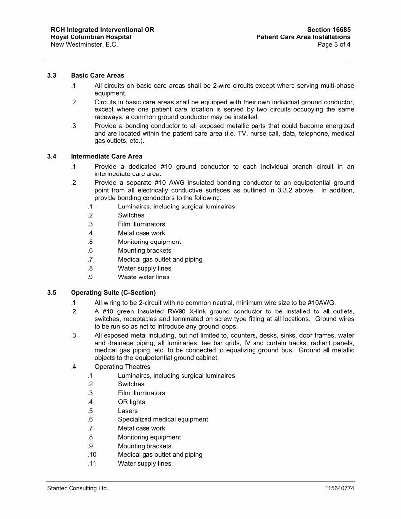
RCH Integrated Interventional OR Royal Columbian Hospital New Westminster, B.C.
Section 16685Patient Care Area Installations
Page 3 of 4
Stantec Consulting Ltd. 115640774
3.3 Basic Care Areas .1 All circuits on basic care areas shall be 2-wire circuits except where serving multi-phase
equipment. .2 Circuits in basic care areas shall be equipped with their own individual ground conductor,
except where one patient care location is served by two circuits occupying the same raceways, a common ground conductor may be installed.
.3 Provide a bonding conductor to all exposed metallic parts that could become energized and are located within the patient care area (i.e. TV, nurse call, data, telephone, medical gas outlets, etc.).
3.4 Intermediate Care Area .1 Provide a dedicated #10 ground conductor to each individual branch circuit in an
intermediate care area. .2 Provide a separate #10 AWG insulated bonding conductor to an equipotential ground
point from all electrically conductive surfaces as outlined in 3.3.2 above. In addition, provide bonding conductors to the following:
.1 Luminaires, including surgical luminaires
.2 Switches
.3 Film illuminators
.4 Metal case work
.5 Monitoring equipment
.6 Mounting brackets
.7 Medical gas outlet and piping
.8 Water supply lines
.9 Waste water lines
3.5 Operating Suite (C-Section) .1 All wiring to be 2-circuit with no common neutral, minimum wire size to be #10AWG. .2 A #10 green insulated RW90 X-link ground conductor to be installed to all outlets,
switches, receptacles and terminated on screw type fitting at all locations. Ground wires to be run so as not to introduce any ground loops.
.3 All exposed metal including, but not limited to, counters, desks, sinks, door frames, water and drainage piping, all luminaries, tee bar grids, IV and curtain tracks, radiant panels, medical gas piping, etc. to be connected to equalizing ground bus. Ground all metallic objects to the equipotential ground cabinet.
.4 Operating Theatres .1 Luminaires, including surgical luminaires .2 Switches .3 Film illuminators .4 OR lights .5 Lasers .6 Specialized medical equipment .7 Metal case work .8 Monitoring equipment .9 Mounting brackets .10 Medical gas outlet and piping .11 Water supply lines

RCH Integrated Interventional OR Royal Columbian Hospital New Westminster, B.C.
Section 16685Patient Care Area Installations
Page 4 of 4
Stantec Consulting Ltd. 115640774
.12 Waste water lines
3.6 Retractable Pneumatically Operated in Operating Suites .1 Division 16 is to supply and install all wiring to devices integral with the operating theatre
retractable ceiling columns. Ensure that entire installation will meet CSA Z32-04 voltage drop requirements, including installation in columns. Co-ordinate with the appropriate division.
3.7 Testing .1 Refer to Section 16073.
3.8 Labels .1 Label all receptacles in rooms containing patient care areas with labels indicating
“Housekeeping” or “Electric Bed Only”. Patient care receptacles do not require labeling in addition to those specified in section 16040.
END OF SECTION

RCH Integrated Interventional OR Royal Columbian Hospital New Westminster, B.C.
Section 16700General Provisions For Electronic /
Computerized EquipmentPage 1 of 2
Stantec Consulting Ltd. 115640774
1 GENERAL
1.1 Scope .1 Electronic components forming parts of computerized equipment and system controls are
sensitive to transients in electrical power lines and to short duration power outages. Provide protection against disruption caused by these conditions.
.2 Many electronic loads are non-linear. AC to DC convertors (rectifiers) and switching mode power supplies are examples of loads in which the load current is not proportional to the instantaneous voltage, or is discontinuous. Such non-linear loads create considerable harmonic distortion on the electrical system supplying the loads, even when the source voltage is a clean sine wave. The non-linear loads will distort that voltage wave, making it nonsinusoidal. Prevent this effect.
.3 Computerized equipment may generate spurious emissions in the form of conducted and radiated electrical/electromagnetic interference. The operation of sensitive electronic equipment may be impeded by such omissions. Ensure electromagnetic compatibility is complied with.
.4 For each and every system specified in Section 16700 to Section 16799, provide single line riser diagram depicting room location of every device in the system and mount diagram in suitably sized glass frame mounted adjacent to respective main control cabinet.
1.2 Transient Protection .1 The system shall be protected against transients in the power system and in the
communication and signalling lines (i.e. spikes, glitches or surges). .2 Protection shall be for both common and differential modes. .3 The protection shall comply with the requirements of IEEE Standard 472 (ANSI/IEEE
C37.90) titles "Guide For Surge Withstand Capability Tests". .4 The vendor shall install the devices within his equipment enclosure or case, and clearly
label or otherwise identify the components used.
1.3 Memory Protection .1 Provide protection against memory loss due to short duration power failures. .2 This protection shall take the form of an internal auxiliary power supply for
microprocessor and memory components unless it is built from non-volatile components. .3 The equipment involved shall retain its status during interruptions lasting up to 20
seconds. It shall not be necessary to reload, reset or reprogram such equipment. .4 The equipment is not expected to continue functioning during the power outage.
Indicating lights and other signals may cease momentarily. However, upon power restoration (either normal or emergency) shall regain its status and resume its operation with no ill effect due to the interruption.
.5 The equipment shall indicate failure of auxiliary power supply by pilot light, message or other acceptable means.
1.4 Non-Linear Loads .1 Provide line filters to reduce the harmonic content of non-linear loads. Such filters shall
be mounted inside the equipment enclosure (the enclosure shall be increased in size if necessary) and shall limit total Distortion Factor (harmonic factor) to 3% as defined and

RCH Integrated Interventional OR Royal Columbian Hospital New Westminster, B.C.
Section 16700General Provisions For Electronic /
Computerized EquipmentPage 2 of 2
Stantec Consulting Ltd. 115640774
measured in ANSI/IEEE Std 519 titled: "Guide for Harmonic Control and Reactive Compensation of Static Power Converters."
1.5 Electromagnetic Compatibility .1 Emission Limits:
.1 Equipment emission of electromagnetic radiation shall be limited to Class-B of FCC RULES PART-15 subpart - J as tested in accordance with FCC measurements procedure MP-4 titled: "FCC measurement of Radio Noise Emission from Computing Devices".
.2 The Consultant shall be notified where the above requirement cannot be met. The Consultant may authorize Class-A qualification or any other qualification of limited electromagnetic emission.
.2 Susceptibility Limits: .1 Equipment shall perform normally in presence of electromagnetic field of one
V/m in accordance with ANSI/IEEE C63.12 titled: "Recommended Practice on Procedures for Control of System Electromagnetic Compatibility".
.2 The susceptibility to power conducted emission of electromagnetic radiation shall be one volt as defined and measured in the standard in 1.5.2.1.
.3 Equipment shall be capable of performing on supply systems containing notches without false triggering of circuits. This should be for notch depth of 0.7 of the rated maximum line voltage and width of 250 microseconds as stipulated in the standard in 1.4.1.
.3 The Consultant shall be notified where equipment does not meet the requirements in 1.5.2 so that corrective measures can be sought.
1.6 Shop Drawings .1 For all section 16700 through 16799, shop drawing submission is to include a detailed
riser diagram and equipment layout showing all patching, outlet locations, equipment locations, and labelling information. These diagrams are to be modified through the course of construction and provided as part of the as-built documentation. These diagrams are also to be suitably mounted in the appropriate equipment/communication rooms.
2 PRODUCTS
2.1 General .1 Provide CSA approved products capable of performing as specified.
3 EXECUTION
.1 Field test equipment not complying with 1.2.3.
.2 Demonstrate memory protection and memory protection failure by field test.
.3 The Hospital/Owner may test equipment for harmonic distortion and RFTI. Remove and replace any non-complying equipment with complying equipment without additional cost to the Hospital/Owner.
END OF SECTION

RCH Integrated Interventional OR Royal Columbian Hospital New Westminster, B.C.
Section 16705Fire Alarm System
Page 1 of 8
Stantec Consulting Ltd. 115640774
1 GENERAL
1.1 Related Work .1 Section 16010 - General Electrical Provisions
1.2 Regulatory Requirements .1 The fire alarm system to be designed and installed to meet the following applicable
standards: .1 CSA Standard C22.1, Canadian Electrical Code, Part 1, current edition bulletins
of the Electrical Energy Inspection Division. .2 Standard for Installation of Fire Alarm System CAN/ULC S524. .3 Standard for Verification of Fire Alarm System CAN/ULC S537. .4 The British Columbia Building Code. .5 Elevator Code CAN3-B44-M85.
.2 Installation subject to approval of consultant and fire marshal for final acceptance.
1.3 Scope .1 Furnish all labour, material and equipment necessary to expand the existing GE fire
alarm system into the renovated area. Make modifications to the existing fire alarm system as indicated in the drawings and specified herein.
.2 Include all wiring and material required to complete the installation. Items obviously necessary or reasonably implied to complete the work are to be supplied as if indicated on the drawings and called for in the specifications.
.3 All new components shall be ULC listed and approved for use on the intended equipment and to be compatible to the existing Siemens fire alarm system. Coordinate on site as required.
.4 Work Included: .1 provide new addressable detectors, anciliary relays, and signalling devices as
indicated on the drawing .2 connect to existing fire alarm panel as required .3 modify to existing annunciators as required. .4 perform all the required programming and verification as required. .5 Update fireworks program and graphic as required.
1.4 System .1 Fire alarm system components shall match existing.
1.5 Shop Drawings .1 Comply with requirements of Section 16010. .2 Shop drawings to be submitted for all components of the fire alarm system. Indicate
equipment layout, zoning, wiring diagrams, annunicators.
1.6 Approvals .1 Refer to Section 16010.

RCH Integrated Interventional OR Royal Columbian Hospital New Westminster, B.C.
Section 16705Fire Alarm System
Page 2 of 8
Stantec Consulting Ltd. 115640774
1.7 Warranty/Service .1 System installer to include with his base tender price a guarantee stating:
.1 Service to be provided on system within 24 hours of call origination during the warranty period.
.2 Full warranty on new system to be provided for a period of 12 months.
.3 During warranty period the system installer at his expense to repair and replace all such defective work and other work to the new system damaged thereby which fails or becomes defective during the term of the warranty, provided that such failure is not caused by improper usage or physical damage.
.4 Should the system installer fail to comply with Sub-item 1.1, work will be performed by others at his expense.
.5 Warranty date to commence from date of final acceptance of this work.
1.8 Training .1 System installer to conduct training program for designated maintenance and operating
personnel. Program to include but not be limited to the following: .1 Operation: designated personnel to be trained to accomplish and understand all
aspects of system operation. .2 Maintenance: designated personnel to be trained to perform routine
maintenance on the system. .2 Training period schedule to be established by the Consultant. Training periods to take
place after building completion system verification and prior to building occupancy. .3 Allow for two four hour training seminars on separate days.
2 PRODUCTS
2.1 Addressable Control Modules .1 Addressable control elements to meet or exceed the following technical requirements:
.1 Compatible with main fire alarm system.
.2 Field programmed.
.3 Individually identifiable.
.4 Supervised.
.5 May be operated by any one or group of identifiable devices.
.6 May be operated from control centre or automatically by system.
.7 Contact rating: .5 amperes 120 volts AC, 2 amperes at 24 volt DC, with one (1) set of Type C contacts.
.8 Ambient Temperature: 0°C - 40°C.
.9 Ambient Humidity: 0 - 93%.
.10 Complete with lamicoid identification on cover identifying address and device controlled.
2.2 Addressable Detector Bases .1 Addressable detector bases to meet or exceed following technical requirements:
.1 Compatible with main fire alarm system.
.2 Field programmable.
.3 Supervised, including removal of specified plug-in detector devices.
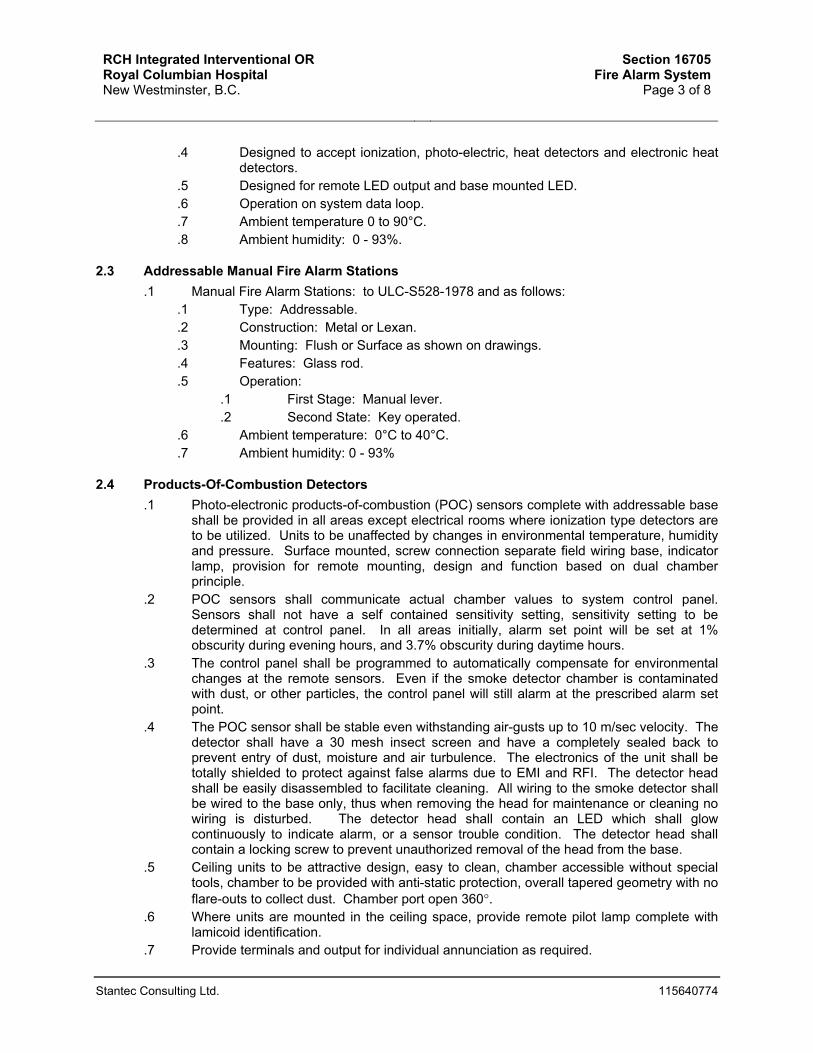
RCH Integrated Interventional OR Royal Columbian Hospital New Westminster, B.C.
Section 16705Fire Alarm System
Page 3 of 8
Stantec Consulting Ltd. 115640774
.4 Designed to accept ionization, photo-electric, heat detectors and electronic heat detectors.
.5 Designed for remote LED output and base mounted LED.
.6 Operation on system data loop.
.7 Ambient temperature 0 to 90°C.
.8 Ambient humidity: 0 - 93%.
2.3 Addressable Manual Fire Alarm Stations .1 Manual Fire Alarm Stations: to ULC-S528-1978 and as follows:
.1 Type: Addressable.
.2 Construction: Metal or Lexan.
.3 Mounting: Flush or Surface as shown on drawings.
.4 Features: Glass rod.
.5 Operation: .1 First Stage: Manual lever. .2 Second State: Key operated.
.6 Ambient temperature: 0°C to 40°C.
.7 Ambient humidity: 0 - 93%
2.4 Products-Of-Combustion Detectors .1 Photo-electronic products-of-combustion (POC) sensors complete with addressable base
shall be provided in all areas except electrical rooms where ionization type detectors are to be utilized. Units to be unaffected by changes in environmental temperature, humidity and pressure. Surface mounted, screw connection separate field wiring base, indicator lamp, provision for remote mounting, design and function based on dual chamber principle.
.2 POC sensors shall communicate actual chamber values to system control panel. Sensors shall not have a self contained sensitivity setting, sensitivity setting to be determined at control panel. In all areas initially, alarm set point will be set at 1% obscurity during evening hours, and 3.7% obscurity during daytime hours.
.3 The control panel shall be programmed to automatically compensate for environmental changes at the remote sensors. Even if the smoke detector chamber is contaminated with dust, or other particles, the control panel will still alarm at the prescribed alarm set point.
.4 The POC sensor shall be stable even withstanding air-gusts up to 10 m/sec velocity. The detector shall have a 30 mesh insect screen and have a completely sealed back to prevent entry of dust, moisture and air turbulence. The electronics of the unit shall be totally shielded to protect against false alarms due to EMI and RFI. The detector head shall be easily disassembled to facilitate cleaning. All wiring to the smoke detector shall be wired to the base only, thus when removing the head for maintenance or cleaning no wiring is disturbed. The detector head shall contain an LED which shall glow continuously to indicate alarm, or a sensor trouble condition. The detector head shall contain a locking screw to prevent unauthorized removal of the head from the base.
.5 Ceiling units to be attractive design, easy to clean, chamber accessible without special tools, chamber to be provided with anti-static protection, overall tapered geometry with no flare-outs to collect dust. Chamber port open 360°.
.6 Where units are mounted in the ceiling space, provide remote pilot lamp complete with lamicoid identification.
.7 Provide terminals and output for individual annunciation as required.

RCH Integrated Interventional OR Royal Columbian Hospital New Westminster, B.C.
Section 16705Fire Alarm System
Page 4 of 8
Stantec Consulting Ltd. 115640774
.8 Duct mounting POC detectors to be complete with addressable module, duct casting, sampling tubes for installation in air systems and pilot lamp.
.9 Detectors to meet both ULC-S529-1978 and UL-268 standards.
2.5 Combination Motorized Fire/Smoke Dampers .1 Dampers shall be motorized combination fire/smoke dampers which are normally closed
(powered to be open). Division 15 shall provide and install the dampers. Division 16 shall wire and connect the dampers to the nearest emergency circuit having sufficient spare capacity. Division 16 shall also provide for damper shutdown through the fire alarm system. Smoke dampers are to close on first stage fire alarm from adjacent areas. Ensure proper ULC approved wiring methods are utilized, i.e. one wire, one terminal. Refer to Division 15 drawings for locations of all fire smoke dampers.
2.6 Wire And Cable .1 Conductors: Copper, to CSA C22.2 and No.75-M1983 and as follows:
.1 Conductor Insulation: Minimum rating 300 volts. Single conductor RW90 X-link. Multi-conductor cables 105°C with outer PVC jacket, colour coded, FAS rated.
.2 Conductor sizes as follows: .1 Minimum conductor size for alarm initiating circuits shall be #18 AWG. .2 Minimum conductor size for signal circuits shall be #16 AWG. .3 Minimum conductor size for AC circuits shall be #12 AWG. .4 Minimum conductor size for visual signal appliance circuits shall be #14
AWG. .5 Size all fire alarm wiring for maximum 3% voltage drop at maximum load
at last device in run. .2 All wiring for systems to be PVC insulated, shielded, twisted pair, multi-conductor or
coaxial, as called for or as required. All wiring for systems to be installed in conduit. .3 Selection of type of cable to be at discretion of system installer but the system meeting all
code requirements, when complete, must perform to the complete satisfaction of the Owner. All wiring to be terminated in terminal panels, junction boxes, etc. on suitable terminal strips or blocks, and to be neatly installed, laced and tagged where required. All terminals in terminal panels and junction boxes to be made with solderless connectors to terminal blocks with separate terminal for each conductor.
3 EXECUTION
3.1 Installation .1 Install devices at locations indicated and in accordance with the manufactureer’s layout
drawings. .2 Each device shall be clearly identified with its zone and address number, using machine-
printed clear adhesive tape with black lettering. .3 Mounting heights for devices:
.1 Manual stations at same height as light switches (1370mm)
.2 Audible signal devices at 2300mm above floor
.3 Visual signal devices at 2300mm above floor
.4 End-of-line devices at 1800mm above floor. .4 All fire alarm system junction boxes, conduits, and wiring shall be painted and identified.

RCH Integrated Interventional OR Royal Columbian Hospital New Westminster, B.C.
Section 16705Fire Alarm System
Page 5 of 8
Stantec Consulting Ltd. 115640774
.5 All fire alarm conduits and BX drops shall be identified with a red band at 3 meter intervals and at all wall or slab penetrations.
.6 Sprinkler devices shall be wired for wet areas using liquidtight flexible conduit. Junction boxes less than 1800mm away from the sprinkler device shall also be suitable for wet are installation.
.7 Door mags and door hold-open devices shall have their respective power circuit numbers identified on them in conspicuous location. Labels shall be black text on clear adhesive tape.
.8 Integrate the fire alarm system with the following systems as indicated and/or as required by code or standard.
.1 HVAC system
.2 Sprinkler system
.3 Door security system. .9 Wiring shall be installed in conduit and shall be as recommended by the system
manufacturer and as required by the CEC.
3.2 Operation of fire alarm system renovations. .1 During construction, new and existing devices shall be protected from
construction dust, debris, and accidental damage. Devices shall be bagged at all times during which dist is produced in the workspace. Devices shall be unbagged at any time the area is unsupervised, or a fire watch shall be put into effect at the Contractor’s own expense.
.2 Contractor shall be liable to replace, reinstall and reverify any existing device which is found to be inoperable at the end of a construction phase.
.3 Coordinate at all times with the facility maintenance staff with regard to isolating fire alarm zones during renovations. Where possible, fire alarm zones serving areas of construction shall be isolated each day. The fire alarm system shall be re-enabled at the end of each working day, once construction dust has settled. All devices shall be left unbagged , trouble free and operational.
.4 Pull stations shall be made accessible or relocated to an appropriate accessible location at all times during construction or renovation activities.
3.3 Testing .1 Obtain the services of an approved manufacturer’s representative to test and
verify the system operation in accordance with CAN/ULC-S537. This shall be performed for each phase of a project, prior to occupancy, and in accordance with the project schedule.
.2 The manufacturer shall test the operation of all devices, zones and controls affected by the work of the contract.
3.4 Programming .1 This contract to include two (2) software re-programs for all the equipment installed under
this Contract. These software generations to include all memory storage devices and burn-in based on devices, control points and monitor points installed under this Contract.
3.5 Contact Info .1 Scott McQuaig
RCH Integrated Interventional OR Royal Columbian Hospital New Westminster, B.C.
Section 16705Fire Alarm System
Page 6 of 8
Stantec Consulting Ltd. 115640774
END OF SECTION

RCH Integrated Interventional OR Royal Columbian Hospital New Westminster, B.C.
Section 16730GPS Clock System
Page 1 of 1
Stantec Consulting Ltd. 115640774
1 GENERAL
1.1 Related Work .1 Section 16010 - General Electrical Provisions
1.2 System .1 Extend the existing GPS Clock system to the renovated area. Provide sufficient new GPS
clocks as shown on the drawings as required.
2 PRODUCTS
.1 Clocks to match existing and be compatible to existing Primex GPS clock system.
.2 Clocks shall be motor driven and correction armature, shall be 375 mm round black metal complete with 3-wire plug in type connector. Clocks shall be single wall-mount or double-side ceiling mount. Clocks in corridors shall be 12-hour type, clocks in C Section, nursing stations, shall be 24-hour type.
.3 Clocks shall have high impact, shatterproof lens.
3 EXECUTION
3.1 Mounting .1 Wall mounted where indicated on drawings. .2 Test to ensure clocks automatically correct for adjustments made by master controller.
END OF SECTION

RCH Integrated Interventional OR Royal Columbian Hospital New Westminster, B.C.
Section 16732Nurse Call System
Page 1 of 8
Stantec Consulting Ltd. 115640774
1 GENERAL
1.1 Scope .1 Supply and install new nurse call devices as indicated on the drawings and specified
herein. Connect to existing nurse call panel serving the area.
1.2 Warranty .1 System installer to include with their base price a guarantee stating:
.1 Service to be provided on system within 24 hours of a call originating during the warranty period.
.2 Full Warranty on new system to be provided for a period of 12 months.
.3 During the warranty period, the system installer is to, at their expense, repair and replace all defective work and other work to new system damaged thereby which fails or becomes defective during the term of warranty, provided that such failure is not caused by improper usage.
.4 Should system installer fail to comply with sub item .1 above, work will be performed by others at the installer’s expense.
.5 Warranty date to commence from date of final acceptance of this work.
1.3 Shop Drawings .1 Provide single line riser diagram depicting room location of every device in the system.
Upon acceptance of diagram, and completion of Work, mount diagram in suitably sized glass frame mounted adjacent to respective main control cabinet.
.2 Provide riser diagram showing interconnection details with all applicable systems.
.3 Reference 16010 for additional submission details.
1.4 Approvals .1 Rauland to match existing
1.5 Maintenance Manuals .1 Manuals to be furnished as specified in Section 16010.
1.6 General Requirements .1 System to be complete with all necessary components to provide functions required
whether or not each and every item is necessarily mentioned. All components to be production proven models. Custom designed units will only be considered for those items that are not currently available on commercial market. System to be supplied and installed by an established communications contracting firm that is approved by the Consultant.
.2 Selection of system to be made on the basis of quality and suitability of equipment, service facilities available, experience, capabilities, and past performance of the contracting firm.
.3 Before proceeding with installation, successful system installer to submit to the Consultant for approval a complete detailed proposal as outlined in Shop Drawings and Section 16010.
.4 Division 16 to be responsible for supply and installation of all backboards, conduit and pullboxes, and installation of junction boxes, device boxes and terminal panels where

RCH Integrated Interventional OR Royal Columbian Hospital New Westminster, B.C.
Section 16732Nurse Call System
Page 2 of 8
Stantec Consulting Ltd. 115640774
required to provide a complete conduit system. Substantial corrosion resistant pullwires to be installed in all conduit runs.
.5 System contractor to supply all junction boxes, device boxes and terminal panels to Division 16 for installation.
.6 If a particular contracting firm requires more or larger conduit, boxes or panels than that shown on drawings, they are to allow for such changes in tender price. No extras will be allowed for additional conduit or increased conduit, boxes or panel size required to accommodate any particular make of system.
.7 Under no circumstances will the contractor be allowed to reduce conduit and panel sizes or revise layouts without prior written approval of the Consultant.
.8 All wiring for systems to be PVC insulated, shielded, twisted pair, multi conductor or coaxial, as called for or as required. All wiring for systems to be new.
.9 Selection of type of cable to be at discretion of system installer but the system, when complete, must perform to the complete satisfaction of the Consultant and must be free of all interference from feedback, cross-talk, hum, switch and relay noise, etc. All wiring to be terminated in terminal strips or blocks, and to be neatly installed, laced and tagged where required. All terminals in terminal panels and junction boxes to be made with solderless connectors to terminal blocks with a separate terminal for each conductor.
1.7 Tests And Adjustments .1 Upon completion of system installation, tests to be conducted by the system installer to
determine system conformity to the requirements of the specification. Tests to be conducted in presence of Consultant and/or his representative who may suspend or discontinue tests at any time performance is considered unsatisfactory. Resumption of testing to cover the previously untested elements and any completed elements at the discretion of the Consultant.
.2 All equipment or wiring provided by system installer which tests prove to be defective or operating improperly to be corrected or replaced promptly at no additional cost to the Contract.
1.8 System Requirements .1 System to be real-time, microprocessor-based nurse call system. .2 System to provide visual and tone annunciation, and two-way voice communication
between the master stations and staff stations. .3 System at minimum to provide 250 unique call priorities and 4 levels of service. .4 Patient stations to be assignable to twenty (20) levels of call classification by key-in at
master station. .5 Corridor and zone lights to include at least four different lamp colours, each of which may
be steady or flashing to annunciate various call classifications. Zone lights as shown on drawings to indicate general area of call origin.
.6 All calls to be individually annunciated at master station indicating room number, and call classification. All calls to be individually annunciated on all tone stations and on associated dome light(s).
.7 Caregiver to be able to log onto wireless telephone system through master nurse call consoles and assign on-duty status, what rooms will be covered, and what phone will be used. System to be toggled from dayshift to nightshift operation from consoles.
.8 Area control unit to provide each master station connected with its own unique two-way voice communications channel for call processing.

RCH Integrated Interventional OR Royal Columbian Hospital New Westminster, B.C.
Section 16732Nurse Call System
Page 3 of 8
Stantec Consulting Ltd. 115640774
.9 Patient stations to incorporate safety call cord disconnect feature such that, if a call cord is removed from its socket, a priority call will be placed to master station. Call point will sound a continuous tone until the call cord is replaced.
.10 System to be low voltage operation complete with individual power supplies, and memory battery backup.
.11 Major components and connecting cable to all stations to be continuously monitored via satellite control operated software/hardware diagnostics on a per station basis to ensure the system's operational integrity.
.12 Each room nurse call devices and associated room dome light to be capable of standalone operation.
.13 All calls to be automatically routed to wireless nursecall interface server and wireless phone system. Calls to be logged on server and routed to appropriate wireless telephone. All calls to be replicated on digital displays where indicated on plans.
.14 If calls are not responded to within a specified time, call to be routed to alternate caregiver. This is to continue until call is cancelled or acknowledged.
2 PRODUCTS
2.1 Acceptable Manufacturers .1 Rauland to match existing
2.2 Area Control Units .1 Equipment to provide automatic switching, storage, logic, signaling, and interconnection
circuitry required to provide specified nurse call functions and be mounted in a suitable cabinet complete with hinged locking cover.
.2 Equipment to be completely solid state, using integrated circuits, and other semi-conductor devices for all service functions.
.3 The switching, storing, amplifying and signaling circuitry to be mounted on modular printed circuit boards and contain the following:
.1 Solid state flasher circuitry and tone generators to provide a source of intermittent visual and audible annunciation.
.2 Solid state audio amplifier with independent talk/listen controls. Voice switching to be performed by a transistorized switching circuit. Sensitivity control to be provided to set level of operation.
.4 Power Supplies .1 Power supplies to be provided for each central equipment unit. .2 Units to provide all operating power to nurse call system. Plus 30% spare
capacity. .3 Power supplies to be designed for continuous duty operation, overload protected,
filtered and regulated so that emergency AC supply transients do not affect system operation.
.4 Power to be restored automatically upon removal of an overload without resetting or replacing circuit breakers or fuses.
.5 Provide battery backup for control unit to ensure continuous operation in the event of a power failure.
2.3 Staff Station .1 All staff stations to provide two-way voice communications with master station.

RCH Integrated Interventional OR Royal Columbian Hospital New Westminster, B.C.
Section 16732Nurse Call System
Page 4 of 8
Stantec Consulting Ltd. 115640774
.2 Staff station to be fully solid state and consist of formed rigid chassis, subpanel circuit board and high impact non-conductive plastic faceplate.
.3 Station subpanel to consist of rigid printed circuit board with associate electronics and precoded plug-in terminals for ease of installation and maintenance.
.4 Subpanel to include a call button, speaker/microphone, cancel switch, and call and answer lamps.
.5 Speaker/microphone to be moisture resistant and minimum 50 millimetre diameter.
.6 Waterproof stations to be provided in areas as indicated on drawings. Stations to be installed with gaskets, rubber bushings, etc.
.7 Staff station only to be cancelled only at staff presence station in the room.
2.4 Corridor Dome Lights .1 Corridor dome lights to consist of a translucent, heat resistant plastic lens mounted on a
high-impact non-conductive plastic faceplate. .2 Lens to be snap-off type for easy replacement of lamps. No special tools to be required
for maintenance or replacement. .3 All electronics supporting operation of light to be contained within its enclosure. .4 Corridor dome lights shall indicate calls from rooms according to classification. .5 Calls to be distinguished by lamps being on steady and/or flashing at various rates. .6 Provide zone lights matching dome lights as indicated on drawings. .7 The zone dome lights shall match the operation of the corridor some lights in its zone.
3 EXECUTION
3.1 Installation .1 Master station programming to be coordinated with the Consultant and Hospital. .2 Division 16 is responsible to set up series of meetings to determine all programming
requirements. Minute meetings and provide information to Consultant before programming.
.3 All programming is responsibility of Division 16.
.4 Mounting Heights: see electrical drawings/ confirmed on site with Consultant.
.5 All nurse call wiring to be new and in conduit.
.6 Nurse call cabinets to be mounted to conserve room and to house all required components.
.7 Division 16 to provide an emergency circuit to each nurse call cabinet.
.8 Install remote digital display screen as indicated.
3.2 Contact Info .1 Anna Rae – [email protected]
END OF SECTION

RCH Integrated Interventional OR Royal Columbian Hospital New Westminster, B.C.
Section 16743Data / Voice Cabling System
Page 1 of 9
Stantec Consulting Ltd. 115640774
1 GENERAL
1.1 Related Work .1 Refer to and coordinate with Electrical Drawings and Specifications. .2 Section 16010 – General Provisions
1.2 Scope .1 Supply and install a complete voice / data cabling system as indicated on the drawings
and specified herein. System to be complete with all data/telephone jacks, wallplates, equipment racks, patch cables, cross-connect wiring, cable management systems, patch panels, and cable to form a complete cabling system and shall meet Fraser Health Telecommunications Technical Standards.
.2 Contractor to coordinate all labelling of outlets, wiring, consolidation points and wiring blocks with Owner and Consultant. All wiring blocks, cables, outlets and consolidation points are to be labelled.
.3 Conduit, pullboxes, junction boxes, gang boxes, and cable tray by Electrical Contractor. Coordinate installed conduit routing with Electrical Contractor. Coordinate exact quantities and locations with Electrical Contractor.
.4 If this specification is in conflict with latest version of Fraser Health Telecom standard, the Fraser Health standard shall be used.
1.3 Acceptable Standards .1 Fraser Health Telecommunications Technical Standards. .2 ISO / IEC 11801 Information Technology - Generic Cabling for Customer Premises. .3 ANSI / TIA / EIA-568-B Commercial Building Telecommunications Cabling Standard. .4 ANSI / TIA / EIA-569 Commercial Building Standards for Telecommunication Pathways
and Spaces. .5 ANSI / TIA / EIA-606 Administration Standard for the Telecommunications Infrastructure
of Commercial Buildings. .6 ANSI / TIA / EIA-607 Commercial Buildings Grounding and Bonding Requirements for
Telecommunications. .7 Building Industries Consulting Services, International (BICSI) Telecommunications
Distribution Methods manual (TDMM).
1.4 Shop Drawings .1 Refer to Section 16010. .2 Shop drawings to be submitted as outlined herein and contain all items within one
complete submission. .3 Shop drawings which are submitted incomplete will be returned to Contractor without
review. .4 Shop drawings to include a complete material list with manufacturer, style, model number
and quantity. Wire and cable to be included in material list. .5 Shop drawings to include manufacturer's specification sheets with photographic depiction
of all system components. Specification and descriptive data to include dimension, weight, appearance, connection provisions, materials, metal gauges and operating specification, characteristics, features and controls.
.6 Shop drawings to include the following diagrams:

RCH Integrated Interventional OR Royal Columbian Hospital New Westminster, B.C.
Section 16743Data / Voice Cabling System
Page 2 of 9
Stantec Consulting Ltd. 115640774
.1 Layout drawings for IDC blocks and outlets, including approved labelling scheme.
.2 Cable details, including type and electrical characteristics.
.3 Complete engineering drawings of all custom made components indicating all materials, gauges, finishes and wiring diagrams.
.4 Complete system block diagrams indicating all components, interconnections and cabling routing.
.5 Complete system wire and cable designation schedule indicating origin, terminus, origin terminal identification, terminus terminal identification, cable function, cable type and cable designation, at each demarcation point.
.6 Under no circumstances will wiring schematics or typical wiring details be considered as circuit diagrams.
1.5 Operating Manuals .1 Refer to Section 16010. .2 Operating manuals to be furnished as specified herein. Operating instructions to consist
of the following: .1 Individual factory issued manuals containing all technical information on each
type of equipment installed. In event such manuals are not available from the factory, system installer to establish same and compile within the manual to satisfaction of the Owner.
.2 Each manual to contain a system parts list, a parts list for individual components, detailed schematics and recommended maintenance procedures. Advertising brochures or operational instructions shall not be considered as technical manuals.
.3 Engineering drawings depicting layout and interconnection of all system components and as-built cabling layout, including all changes and cabling information.
.3 In addition to the above described manuals, system installer to include all shop and layout drawings, wiring schedules and single line block drawings in the manuals.
1.6 General Requirements .1 System to be complete with all necessary components to provide functions required
whether or not each and every item is necessarily mentioned. All components to be production proven models. Custom designed units will only be considered for those items that are not currently available on commercial market and approved by Consultant. System to be supplied and installed by an established communications contracting firm that is approved by Owner.
.2 Selection of system to be made on the basis of quality and suitability of equipment, service facilities, and past performance of contracting firm.
.3 Before proceeding with installation, successful system installer to submit to Owner for approval a complete detailed proposal as outlined in Clause 1.4, Shop Drawings.
.4 All wiring for systems to be PVC insulated, unshielded, twisted pair. All wiring to be installed in conduit and tray system unless otherwise specified.
.5 The system, when complete, must perform to complete satisfaction of Owner and must be free of all interference from cross-talk, hum, switch and relay noise, etc. All wiring in Electrical and Communication Rooms to be terminated on IDC blocks and to be neatly installed, bundled, supported, laced and labelled.

RCH Integrated Interventional OR Royal Columbian Hospital New Westminster, B.C.
Section 16743Data / Voice Cabling System
Page 3 of 9
Stantec Consulting Ltd. 115640774
.6 Personnel installing communications cabling shall be trained and conversant with communications cabling practices required for this project. Proof of certification must be provided prior to commencement of work.
.7 The system shall be installed by a contractor designated and trained by the manufacturer of being capable to do so and shall provide written confirmation of this fact.
1.7 Warranty/Service .1 System installer to include with his base tender price a guarantee stating:
.1 Full warranty on new system to be provided for fifteen (15) years.
.2 Service to be provided on system within 24 hours of call origination during the warranty period.
.3 During warranty period system installer at his expense to repair and replace all such defective work and other work to new system damaged thereby which fails or becomes defective during term of warranty, provided that such failure is not caused by improper usage or physical damage.
.4 Warranty date to commence from date of Final Acceptance of this work.
.5 System to be certified to meet and or exceed current Category 6 standards of speed and of performance for the duration of the warranty as specified by the manufacturer.
1.8 Training .1 Provide 2 hours of maintenance training for 4 individuals divided into 2 separate
sessions.
2 PRODUCTS
2.1 General .1 All horizontal products that are installed for data, intercom, and voice,
when combined, shall meet Cat 5e permanent link performance as per TIA/EIA 568-B.1 and B.2. The products installed for the end-to-end solution shall have been tested by an independent testing agency, such as UL or ETL, to ensure that the integrated system installed meets channel performance. The manufacturer(s) of the proposed solution must have an ISO 9000 program in place to ensure the channel testing is a standard part of their quality assurance.
.2 The structured cabling system shall be a complete, end-to-end Belden system.
2.2 Cable .1 All All horizontal telecommunications cabling shall be BELDEN IBDN GigaFlex,
(1212) 4 pair, 100 ohm, UTP, 24 AWG, Solid, Category 5e
2.3 Termination Hardware .1 All data, intercom and voice cables shall be terminated on Category 5e, 8
position modular (RJ45) jacks at the work areas. Belden EZ-MDVO Modules.
.2 All 8-position modular jacks (RJ45) terminations shall be made using the TIA/EIA 568A pin configuration.
.3 All horizontal cables shall terminate in the telecommunications closets

RCH Integrated Interventional OR Royal Columbian Hospital New Westminster, B.C.
Section 16743Data / Voice Cabling System
Page 4 of 9
Stantec Consulting Ltd. 115640774
using IDC cross connects on the wall. Where existing IDC blocks exist, they shall be replaced with new whenever feasible. In new telecommunications closet, IDC shall be mounted on Belden 12-Connector GigaBix mount. GigaBix cable management module shall be installed behind GigaBix mount to facilitate cable routing. The data drops shall be extended from a separate IDC cross connect to a rack mounted 8-position modular plug (RJ45) using a harness cable.
.4 All data and voice jacks shall be the same colour (blue). Where Cat6 is used under special applications, the jack colour shall be purple.
.5 All wall-mounted coverplates shall be 4 port single gang Belden Interface wall plates or FH approved equivalent.
2.4 Cross Connect & Patch Cables .1 Data cross-connect jumpers shall be GigaBIX Cross-Connect Category 5e
jumper wires or better. The installation of the data jumper wire is part of this scope of work. Unless otherwise noted on plans, for each face plate that contain 3 cables 1 is to be cross connected, i.e. for a standard workstation there are 3 cables installed 1 Telephone, 1 Data and 1 Spare.
.2 The quantity of patch cords shall be 10% of the horizontal data cables per telecommunications closet. Minimum of 2 per telecommunications closet. Patch cords shall be 3.0m long (10ft.) and 4 pair. Each end shall match the IDC system installed, i.e. if wall distribution IDC is BIX then patch cords to have BIX ends.
3 EXECUTION
3.1 Installation .1 The installation shall meet the requirements of industry practices as recommended by the
manufacturer whose products are being installed, and the TIA/EIA Standards (except where this Technical Standard differs). The Installation shall also meet the Fraser Health Telecommunications Standard and BICSI Telecommunications Cabling Installation Manual.
.2 Install cable from the wall outlet to the telecommunications closet serving that area. The cables shall be continuous. Terminate the cable on the appropriate termination hardware.
.3 The scope of work includes the installation and termination of the 4 pair harness cables from the IDC terminations to the owner equipment on the rack. It also includes the installation of the associated jumper wire to complete the data cross connection. In acute sites, one horizontal data cable per outlet shall be cross connected to the switch. In community sites, one horizontal data cable and one horizontal spare cable shall be cross connected to the switch. All horizontal cables shall be terminated in the work area. No cables shall remain unterminated in the ceiling space.
.4 Walls shall have102 mm x 102 mm (4”x 4”) outlet boxes installed with a single gang mud ring. Outlets shall not be installed back-to-back inside the wall. A minimum 150mm (6”) horizontal clearance shall be maintained between the two. All outlets shall be positioned to clear millwork and furniture and to enable easy and unobstructed access. A 19 mm (¾”) conduit shall be installed from the outlet box to the ceiling space. The conduit shall have a grounding bushing installed in the ceiling space and be installed such that the minimum bend radius of the cable is not exceeded. If the wall is an existing internal

RCH Integrated Interventional OR Royal Columbian Hospital New Westminster, B.C.
Section 16743Data / Voice Cabling System
Page 5 of 9
Stantec Consulting Ltd. 115640774
partition with no insulation then a low voltage mounting bracket with open wiring is acceptable providing a grommet is used at all stud/plate penetrations.
• Conduit shall be EMT or rigid steel. • Flexible metallic and PVC conduit shall not be used in pour concrete unless
specified. • All conduits shall have sweeping bends with inside radius of no less than six (6)
times the internal diameter of the conduit. For conduit 50mm (2”) or larger, the radius shall be no less than ten (10) times the internal conduit diameter. Fittings such as LB type joints shall not be used. • Conduits shall be attached to the edge of cable tray with a conduit bracket designed for this purpose. If this is not possible, conduit shall be stubbed within 150 mm above the tray and terminate in a bonding type bushing. • Where conduits are mounted high above cable tray, 90º bends for conduits shall be provided with conduit ends stubbed 150 mm above the tray in a bonding type bushing. This water fall effect shall reduce the strain on cables. • When installing cable in conduit, cable fill shall not exceed 40% fill ratio where there are zero bends in the raceway, and not to exceed 28% where there are two 90º bends in the run. • A pull tape shall be left in all raceways after installation of the cables. Pull tape shall be Greenlee 4435 or approved equal. All empty raceway shall be clearly and permanently marked at both ends to indicate destination and function. • Conduits and cables containing line voltage conductors (including branch circuit wiring) shall not be supported from the supports used for Telecommunications cable trays or from the trays themselves. • When zone conduit system is used, connect the system to each room ceiling space entered with a minimum 300 mm X 300 mm X 150 mm (12” x 12” X 6”) deep pull-box. Conduits to outlets in the room shall be from this pull-box. • When zone conduit system is not installed in readily accessible false ceiling space, access hatches shall be installed at a nominal spacing of 9 m (30’). • Where new walls are added, conduits shall be installed inside the wall. • Where required, conduits, fittings and duct sleeves shall be installed prior to pouring of concrete. They shall be placed neatly following building grid lines and close to building structure to keep furring to a minimum.
3.2 Testing .1 Test all runs upon completion of permanent terminations, using instrumentation
acceptable to the Consultant. Before commencing testing, submit sample test data sheets and information with respect to test instrumentation to be used.
.2 Acceptable Test Instruments: .1 Copper: Fluke DSP-4000 / Microtest Omni scanner .2 Fibre: OTDR and Power Source / Attenuation Meter
.3 Copper Media: .1 Test for the following:
.1 Continuity
.2 Pair placement and polarity.
.3 DC resistance
.4 Characteristics at highest contemplated frequency: .1 Attenuation .2 Mutual Capacitance. .3 Near-end crosstalk (NEXT) - for each pair.
RCH Integrated Interventional OR Royal Columbian Hospital New Westminster, B.C.
Section 16743Data / Voice Cabling System
Page 6 of 9
Stantec Consulting Ltd. 115640774
.5 Run length.
.6 Return loss. .4 Fibre Optic Media:
.1 Ensure that test instrument is temperature-stabilized or is temperature-independent or temperature-compensated before commencing test.
.1 Test for the following:
.2 Run attenuation at 850 and 1300 nm wavelengths.
.3 Run length.
.4 Smooth light continuity with no loss spike. .5 Each spool of copper and fibre optic cable shall be tested for continuity prior to being
installed.
3.3 Report .1 Record results in tabular form. .2 Segregate horizontal runs, inter-room runs, and risers by category or run and by type of
cable. .3 Present horizontal results in ascending order. .4 Report Submission:
.1 Submit three (3) reports printed on 215 mm by 280 mm white paper.
.2 Submit two (2) reports prepared in electronic form using Microsoft Excel or Lotus 1-2-3 on 15 mm or 90 mm diskettes.
END OF SECTION

RCH Integrated Interventional OR Royal Columbian Hospital New Westminster, B.C.
Section 16799Testing And Training
Page 1 of 2
Stantec Consulting Ltd. 115640774
1 GENERAL
1.1 Intent .1 The Consultant and Division 16 to provide complete testing and demonstration /
instruction sessions to familiarize Owner's operation and maintenance personnel with electrical systems and their operation and maintenance.
1.2 Manufacturer's Site Services .1 Division 16 to arrange and pay for appropriately qualified manufacturers' representatives
to provide or assist in providing electrical equipment and systems demonstration and instruction as specified herein.
.2 The manufacturer's technical representative shall visit the site four weeks prior to the scheduled seminar date in order to familiarize himself with the equipment on site.
.3 Two weeks prior to the scheduled seminar date the manufacturer's technical representative shall submit to the Consultant via Division 16, the following:
.1 A letter stating that he has inspected each piece of equipment provided by his firm and found it to be in proper working order.
.2 A neatly typewritten copy (which will be handed out to seminar participants) detailing operations and maintenance information as it will be presented at the seminar. The Consultant must approve all submissions prior to seminar commencement date. This submission shall include the schedules maintenance procedures and checklist charts specified in Section 16031, Electrical Operation and Maintenance Data.
1.3 Contractor/Consultant Coordination .1 Division 16 to establish agendas for demonstration and instruction sessions for approval
of Consultant. Provide proposed demonstration and training agenda for Consultant’s and owner’s approval 2 weeks prior to commencing. Coordinate scheduling of sessions with Consultant.
1.4 O&M Manuals And As-Built Drawings .1 Division 16 shall be responsible to ensure that a copy of the final Operating and
Maintenance Manuals and As-Built drawings are at each seminar.
2 PRODUCTS
2.1 Not Used.
3 EXECUTION
3.1 Testing
.1 Conduct and pay for tests and provide written reports for the following: .1 Nurse call system and communications.
.2 Furnish manufacturer's certificate or letter conforming that entire installation as it pertains to each system has been installed to manufacturer's instructions.
.3 Tests to include but necessarily be limited to:

RCH Integrated Interventional OR Royal Columbian Hospital New Westminster, B.C.
Section 16799Testing And Training
Page 2 of 2
Stantec Consulting Ltd. 115640774
.1 Test every nurse call device for proper operation;
.2 Test every nurse call device for annunciation on wireless handsets;
.3 Check for proper annunciation;
.4 Check handset to handset communication;
.5 Check that wireless handsets can reach and be reached by external line.
.6 Check correct nurse call alarm information is displayed on handsets;
.7 Ensure multiple calls are handled and annunciated properly on all systems. .4 Carry out random witness tests in presence of Engineer. .5 Provide instruments, meters, equipment and personnel required to conduct tests during
and at conclusion of project. If applicable during these tests, equipment shall be disconnected to prevent damage to the solid state control components.
.6 Submit tests results in spreadsheet format in triplicate to Engineer.
3.2 Training .1 System installer to conduct training program for designated maintenance and operating
personnel. Program to include but not be limited to the following: .1 Operation: designated personnel to be trained to accomplish and understand all
aspects of system operation. .2 Maintenance: designated personnel to be trained to perform routine
maintenance on the system. .2 Training period schedule to be established by the Consultant. Training periods to take
place after system completion and prior to system commissioning. .3 Training to include:
.1 Provide complete and comprehensive training and demonstration sessions for the Owner.
.2 Instruct personnel in operation, adjustment, and maintenance of equipment and systems, using provided operation and maintenance data as the basis for instruction.
.3 System installer to come back 90 days after training sessions have been completed and system in use for follow up session and Q & A session. Allow for 2 sessions.
END OF SECTION

RCH Integrated Interventional OR Royal Columbian Hospital New Westminster, B.C.
Section 16901Motors
Page 1 of 1
Stantec Consulting Ltd. 115640774
1 GENERAL
1.1 Related Work .1 Section 16010 - General Electrical Provisions .2 Division 15 - Installation of Mechanical Equipment Motors
2 PRODUCTS
2.1 Motors .1 Motors:
.1 0.37 kW or less to be 120 volts, single phase, 60 Hz.
.2 All motors 0.56 kW and greater to be 575 volts, 3 phase, 60 Hz.
.3 Note: In certain instances where specifically noted, motor voltages will be other than as listed in preceding paragraph.
3 EXECUTION
3.1 Installation .1 Confirm final connections, loads and locations of motors prior to installation. .2 Motors for mechanical equipment installed by Division 15. Locations of motors, conduit
and connection points shown for equipment supplied by Division 15 are for estimating purposes only.
.3 Provide line voltage power supply connections to all mechanical equipment motors.
.4 Verify nameplates full load rating of motor and apply proper overload heaters / setting of overload relay to match same. Submit a report listing all new motors and the rating of this overload protection as part of shop drawings of motor starters.
END OF SECTION

RCH Integrated Interventional OR Royal Columbian Hospital New Westminster, B.C.
Section 16905Motor Starters
Page 1 of 2
Stantec Consulting Ltd. 115640774
1 GENERAL
1.1 Related Work .1 Section 16010 - General Electrical Provisions
1.2 Reference Standards .1 Provide motor protection switches of the EEMAC size listed. Maximum rating of units not
using EEMAC rating to be equivalent to EEMAC size indicated.
1.3 Acceptable Products .1 Cutler Hammer, Square D to match existing where located in existing MCC’s.
2 PRODUCTS
2.1 Manual Motor Protection Switches .1 Single phase manual motor protection switches to be either toggle or key operated
complete with pilot light. Flush or surface mounted as indicated, key operated where indicated.
2.2 Magnetic Motor Protection Switches .1 Each motor protection switch to incorporate the following facilities:
.1 Contactor with 3 pole Class 10 adjustable overload relay.
.2 120 volt holding coil.
.3 Cluster LED type pilot lights in cover.
.4 Reset button, HOA switch or On/Off switch in cover. HOA bezel to be convertible or interchangeable with local-off-remote wording.
.5 Two (2) sets of auxiliary contacts - normally Open in addition to standard auxiliary holding contacts supplied with each contactor making a total of three (3) auxiliary contacts. One (1) set of auxiliary contacts to be convertible to normally closed.
.6 Control transformer primary and secondary fusing - primary fusing to be HRC type.
.7 Control transformer 600/120 volt of sufficient VA to handle operating coil and associated auxiliary controls.
.8 Control terminals wired as per sketch attached.
.9 Support facilities for load sensing ring type CT on Phase C of motor circuit.
.10 Units to be flush and/or surface mounted in EEMAC Type 1 or Type 4 enclosure. Provide dripshield for indoor surface mounted units.
2.3 Combination Motor Protection Switches .1 Three pole magnetic trip moulded case breaker (Motor Circuit Protectors) and operating
handle with lock-off facility. .2 Motor protection switch enclosure "opening" to be restricted by use of a defeater screw
unless switch is in "off" position. .3 Each combination magnetic motor protection switch to include the following facilities:
.1 Magnetic trip moulded case circuit breaker (MCP).

RCH Integrated Interventional OR Royal Columbian Hospital New Westminster, B.C.
Section 16905Motor Starters
Page 2 of 2
Stantec Consulting Ltd. 115640774
.2 Contactor with 3 pole Class 10 adjustable overload relay with single phase protection feature.
.3 120 volt holding coil.
.4 Red cluster LED type pilot light in cover.
.5 Reset button, HOA switch or On/Off switch in cover. HOA bezel to be convertible or interchangeable with local-off-remote wording.
.6 Two (2) sets of auxiliary contacts - normally Open in addition to standard auxiliary holding contacts supplied with each contactor making a total of three (3) auxiliary contacts. One (1) set of auxiliary contacts to be convertible to normally closed.
.7 Control transformer primary and secondary fusing - primary fusing to be HRC type.
.8 Control transformer 600/120 volt of sufficient VA to handle operating coil and associated auxiliary controls.
.9 Control terminals wired as per sketch attached.
.10 Support facilities for load sensing ring type CT on Phase C of motor circuit.
.11 Time delay on relay for indicated motors.
3 EXECUTION
3.1 Installation .1 In finished areas, provide flush mounted manual motor protection switches complete with
stainless steel coverplates. Exclusive of the mechanical rooms, electrical rooms, all motor protection switches to be key operated type complete with pilot light.
.2 Select overload settings to suit full load current of motors installed.
.3 Magnetic motor protection switches to be installed where indicated.
.4 Select overload device trip setting for magnetic motor starters to suit the motors installed.
.5 Provide driphood sprinkler protection for all devices in service areas.
.6 Provide ULC approved relays for shutdown control from fire alarm system as specified in Section 16705.
END OF SECTION

RCH Integrated Interventional OR Royal Columbian Hospital New Westminster, B.C.
Section 16909Disconnects
Page 1 of 1
Stantec Consulting Ltd. 115640774
1 GENERAL
1.1 Related Work .1 General Electrical Provisions: Section 16010
2 PRODUCTS
2.1 Disconnect Switches .1 Single phase disconnect switches: single and/or 2 pole, toggle, key switch as required,
similar to Section 16140. .2 Three phase motor disconnect switches: 3 pole, unfused, 250 or 600 volt as required in
EEMAC Type 1 or Type 4 enclosure. .3 All disconnect switches to be lockable in "Off" position.
2.2 Fused Disconnect Switches .1 Heavy duty, quick make, quick break, visible contact position, lockable in "Off" position. .2 Assembly: modular enclosure. .3 Mechanism: spring assist open/close. .4 Primary contacts: low resistance load contacts with arc quenching. .5 Fuse holders: designed for HRC1-J time delay fuses where noted. .6 Cover: dead-front interlocked with switch. .7 Operation: manual, rotary operating handle. .8 Position indication: external. .9 Fuses: sized to limit let-through current to 18 kA on the basis of 50 kA availability. .10 Auxilliary N.O. contact for elevator fused disconnect switches.
3 EXECUTION
3.1 Installation .1 Install motor and circuit disconnect switches as required by Code or called for in tender
documents.
END OF SECTION

RCH Integrated Interventional OR Royal Columbian Hospital New Westminster, B.C.
Section 16917Motor Control Centres
Page 1 of 3
Stantec Consulting Ltd. 115640774
1 GENERAL
1.1 Connections .1 Provide connection from each MCC and modified MCC to the fire alarm system for fan
control. 1.2 Related Work
.1 Section 16010 - General Electrical Provisions
.2 Section 16020 - Work Included
.3 Section 16021 - Work Not Included
.4 Section 16030 - Tests
.5 Section 16040 - Identification
.6 Section 16045 - Seismic Restraints
.7 Section 16705 - Fire Alarm System
.8 Section 16901 - Motors
.9 Section 16905 - Motor Starters
.10 Section 16909 - Disconnects
.11 Section 16913 - Mechanical Equipment Controls 1.3 Acceptable Products
.1 Square D, Cutler Hammer.
2 PRODUCTS
2.1 Components .1 Unit motor control centres to be of the dead front, assembly of vertical stacks with each
stack containing necessary cubicles to provide equipment required including space as specified or shown on the drawings. Minimum height for one module to be 300 mm and each module to house a combination starter MCP, relays and/or transformer as indicated. Motor control centres to be for 600 volt, 3 phase, 3 wire, 60 Hz application. Motor control centres to have horizontal copper bussing across top and vertical copper bussing down each stack. Main bus capacity to be as indicated on drawing, having bracing and supports suitable to withstand short circuit current up to 50,000 amps symmetrical unless otherwise specifically noted in MCC schedules. Each module of each motor control centre to be connected to the common bus by plug-in style connection stabs. Enclosure shall be dripproof.
.2 Provide terminal entry access panel with sufficient capacity to allow application of clamp-on ammeter.
.3 Each starter or disconnect switch assembly in MCC to be mounted in tub or rack assembly of removable plug-in type with necessary bus connection stabs.
.4 Where blank starter connections are indicated, hinged section to be provided with full copper bussing to receive future rack assemblies. Provide wiring gutter across top and bottom and vertically down each stack of MCC. Wireways to be barriered from busway compartments. Motor control centre components to be designed and constructed for ease of servicing and connection. Connection or terminal blocks not to be at back or rear. Overload devices to be interchangeable and to clearly indicate heater rating from exterior of device. Motor control centres to be constructed in accordance with EEMAC standards for construction of Class I, modified Type B centres with control wiring and control terminals on each module and control wiring extended to control terminal section of MCC.
.5 Each combination magnetic motor protection switch to include the following facilities:

RCH Integrated Interventional OR Royal Columbian Hospital New Westminster, B.C.
Section 16917Motor Control Centres
Page 2 of 3
Stantec Consulting Ltd. 115640774
.1 Magnetic trip moulded case circuit breaker (MCP).
.2 Contactor with 3 pole Class 10 adjustable overload relay with single phase protection feature. All contactors to be full EEMAC rated.
.3 120 volt holding coil.
.4 Red neon type or transformer type pilot light in cover.
.5 Reset button, HOA switch or On/Off switch in cover. HOA bezel to be convertible or interchangeable with local-off-remote wording.
.6 Two (2) sets of auxiliary contacts - normally Open in addition to standard auxiliary holding contacts supplied with each contactor making a total of three (3) auxiliary contacts. One (1) set of auxiliary contacts to be convertible to normally closed.
.7 Control transformer primary and secondary fusing - primary fusing to be HRC type.
.8 Control transformer 600/120 volt of sufficient VA to handle operating coil and associated auxiliary controls.
.9 Control terminals wired as per drawing.
.10 Support facilities for load sensing ring type CT on Phase C of motor circuit. CT supply not included.
.11 Time delay on relay for indicated motor starters. .6 Provide separate hinged door over vertical wire gutter along each stack of starters. .7 Each motor control centre to contain a control terminal section of height indicated on detail
drawing of the motor control centre and to be barriered from adjacent 600 volt section. Control terminal section not to contain any bus work or bus supports. Control terminal section to be complete with solid backpan at rear of MCC stack for installation of control terminals. Control terminal section to be full depth of motor control centre.
.8 Incoming Terminal Compartment: Provide adequately sized compartment for termination of incoming cables. Compartment to contain fully rated main bus extensions with cable lugs. Provide lamicoid nametag labelled "Incoming Terminal Compartment".
.9 Single Phase Starters: Where indicated in Section 16921. Miscellaneous Mechanical Equipment, provide single phase manual motor protection switch with red pilot light, HOA selector switch, auxiliary relay and terminal block interface. HOA switch and motor protection switch shall be mounted in control terminal section door and control relay on backpan of control terminal section. Refer to Sketch ESK #1 for additional wiring details.
.10 Magnetic Motor Starters: .1 Where indicated in Section 16921, Miscellaneous Mechanical Equipment provides
single phase magnetic motor starters complete with OA or HOA selector switch and red push-to-test transformer type pilot light labelled "Run". Mount starter in control terminal section and install controls and controls and pilot devices on control terminal section door.
.2 Starters wired as per ESK-1 and ESK-2.
3 EXECUTION
3.1 Motor Control Centres .1 Each motor control centre to contain starters and spaces as indicated. Arrange starter
units and circuit breakers in groupings shown. Certain alterations will be accepted to suit a particular manufacturer's standard unit layout, however, layout of units per stack to follow that indicated. Starter units are numbered with equipment unit number identification system. All cubicles to be complete with lamicoid engraved nametag (mechanically fastened) giving motor designation or load controlled, voltage and kilowatts.

RCH Integrated Interventional OR Royal Columbian Hospital New Westminster, B.C.
Section 16917Motor Control Centres
Page 3 of 3
Stantec Consulting Ltd. 115640774
3.2 Control Terminal Section .1 Extend control wiring as indicated on typical wiring diagram from each motor control
module to control terminal section. All terminals to be number coded and otherwise suitably identified to indicate which section or module of motor control centre they are associated with and their function. Control wiring diagrams of each typical type with conductor identification clearly shown to be affixed to interior cover of control terminal section.
.2 Control terminal section to house all controls, relays and time delay relays associated with the mechanical system and control systems such as fire alarm system specified in Section 16705.
.3 Relays for fire alarm shutdown systems to be ULC approved and powered from fire alarm panel.
3.3 Time Delay “On” Relay Setting .1 Set time delay on relays of motors on emergency power to allow sequential delay start-up
of motors. Submit a time setting report for all motor starters. 3.4 Field Verification of Existing Motor Control Centres
.1 Verify existing motor control centres where new motor starters will be added.
.2 Confirm the wire size of the existing feeders of the motor control centres to ensure adequacy of its ampacity to support new loads. Submit this report to the consultant together with the shop drawings of new motor starters.
.3 Shop drawings of new starters in existing motor starters shall show elevation drawings to confirm its location relative to existing motor starters.
.4 Retain Cutler Hammer to prepare these shop drawings.
END OF SECTION

Elevation View
Carrier Configuration
Medical Gas Details
Electrical Wiring DetailsA, B, C, D, E, F
__1
__2
__3
__4
Non-Typical Components Required: Not Applicable
I have read the appropriate requirements from the Skytron Pre-Installation Guide for Ergon Skybooms and consulted with the individual
trades. I understand there are specific ceiling height, medical gas, electrical, video / communications and structural requirements that
must be supplied by the customer's representatives to support this project.
REJECTEDACCEPTED AS NOTED
®
MOUNT
REFERENCE
DRAWING
NUMBER
Room Layout
September 4, 2009
5085 Corporate Exchange Blvd. SE Grand Rapids, MI 49512 1.800.SKYTRON ph: 616.656.2900 fx: 616.656.1628
SKYTRON SKYBOOMS are custom built to meet the requirements specified from your facility. Ensure that all of your custom specifications have been included.
DRAWING
DESCRIPTION
SKYBOOM ORDER DRAWING PACKAGE AND DISCLOSURE
prepared for
Royal Columbian Hospital
QUOTE NUMBER: 1915-6
• • • EACH DRAWING MUST BE INITIALED AND DATED • • •
__5
__6
Communications Details
Light Fixture Details
ACCEPTED
! ! P L E A S E R E A D T H E F O L L O W I N G C A R E F U L L Y ! !
Mounting Details
• • • NOTE THAT NOT ALL DRAWINGS WILL BE REQUIRED FOR EACH BOOM • • •
P.O. NUMBER:
DATE:APPROVAL:
TITLE:
Please sign and return to Skytron via fax at 616.656.1628
Issued for Coordination Only on project Tender date, September 8,2009
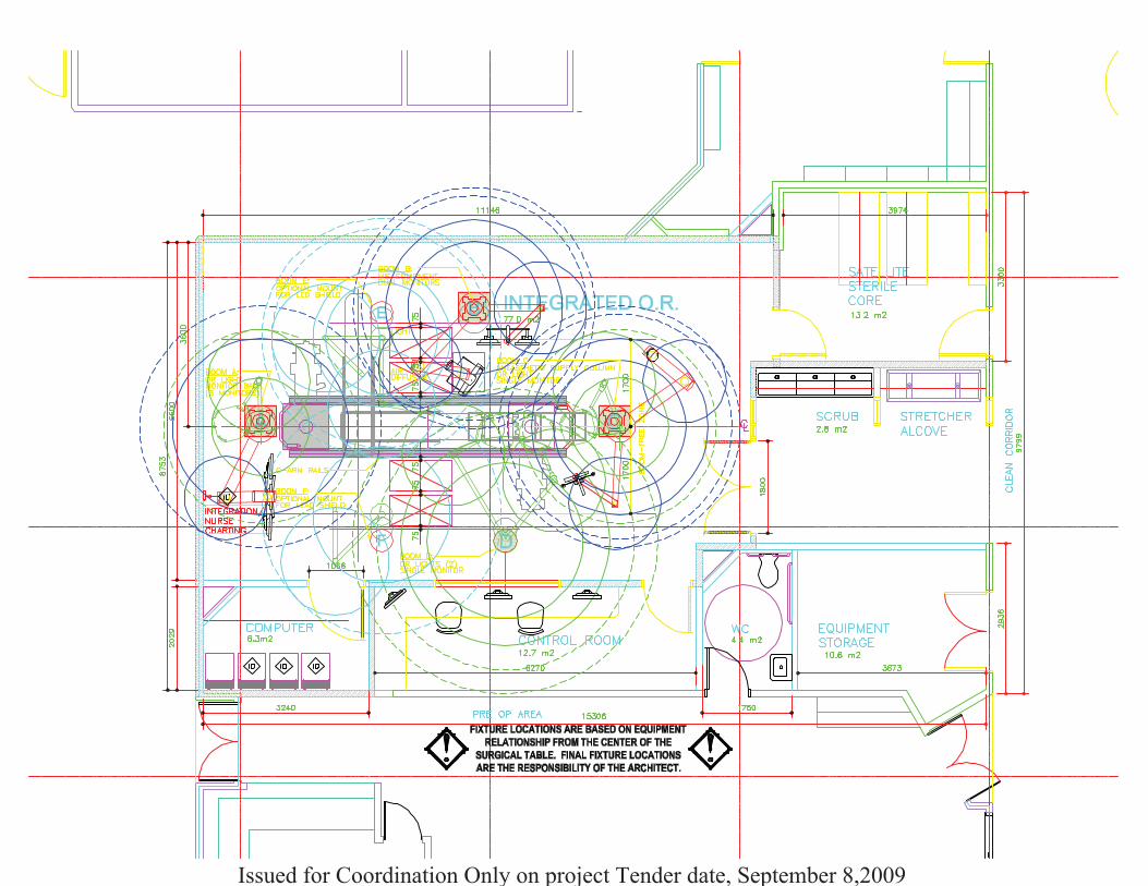
Issued for Coordination Only on project Tender date, September 8,2009

MOMENT LOAD:FIXTURE WEIGHT:
0"
2900 HEIGHTCEILING
FLOOR 0"
467 kg 5638 Nm
A1SHEETINITIAL:
DATE:
DE
SC
RIP
TIO
N:E
LEV
AT
ION
VIE
W
RO
YA
LC
OLU
MB
IAH
OS
PIT
AL
RO
OM
TY
PE
:HY
BR
ID
PR
OJE
CT
NO
:09-
084-
DS
SU
BM
ITT
AL
PLO
TD
AT
E:9
.4.2
009
ATTENTION STRUCTURAL ENGINEER:REFER TO THE ERGON PRE-INSTALL GUIDE PAGE 5
FOR STRUCTURAL REQUIREMENTS
72"
MO
DE
LN
O.:
EC
2EF
C6/
AU
R5
QT
Y:1
RE
VN
O.:
1
75
250
1550
800
290
6001090
2032
REFER TO DATA SHEET
#AUR5 FOR SURGICAL LIGHT
SPECIFICATIONS
1800
FLAT SCREEN MONITORS ARE NOT PROVIDED
Issued for Coordination Only on project Tender date, September 8,2009

120VAC, 10 AMP
GREY
YELLOW
BROWN
GREEN
WHITE
BROWN
ORANGE
GREEN
WHITE
YELLOW
BROWN
GREEN
GREY
UP / DOWN
CONTROL
PUMP HOUSING JUNCTION BOX
ENCLOSURE (18"L X 12"H X 6"D MOUNTED BY OTHERS)
24V CONTROL CONNECTOR
A4SHEETINITIAL:
DATE:
NON-ISOLATED POWER
SYSTEMS
INTERNAL FIXTURE WIRING
TYPICAL WIRE TYPE:
12AWG, 600V, XHHW-2, 90°C
BLUE, BLACK, GREEN
CARRIER UTILITIES PANEL
2 INPUT LEADS
120 VAC, 15 AMP CIRCUIT 1
PUMP DRAW:
2.7 AMP
120VAC, 60Hz, 1PH
DE
SC
RIP
TIO
N:E
LEC
TR
ICA
LW
IRIN
GD
ET
AIL
S
FIXTURE JUNCTION BOX AT MOUNTING PLATE
110VAC FEMALE
IEC PLUG
(FOR MONITOR)H5-010-71 120 VAC, 15 AMP CIRCUIT 2
ATTENTION ELECTRICAL ENGINEER: SPECIFIC CONDUCTOR COLORS AND/OR
WIRING FOR ISOLATEDAPPLICATIONS ARE AVAILABLE UPON REQUEST. REFER TO
THE ERGON PRE-INSTALL GUIDE PAGE 7 FOR STRUCTURAL REQUIREMENTS.
MO
DE
LN
O.:
EC
2EF
C6/
AU
R5
QT
Y:1
RE
VN
O.:
1R
OY
AL
CO
LUM
BIA
HO
SP
ITA
LR
OO
MT
YP
E:H
YB
RID
PR
OJE
CT
NO
:09-
084-
DS
SU
BM
ITT
AL
PLO
TD
AT
E:9
.4.2
009
Issued for Coordination Only on project Tender date, September 8,2009

MOUNTING HUB
(male connectors)
UTILITIES CARRIER
(female connectors)
ALL CABLING TO BE
PROVIDED BY OTHERS
A5SHEETINITIAL:
DATE:
DE
SC
RIP
TIO
N:C
OM
MU
NIC
AT
ION
SD
ET
AIL
S
ATTENTION VIDEO / COMMUNICATIONS / DATA ENGINEER:REFER TO THE ERGON PRE-INSTALL GUIDE PAGE 7
FOR MEDICAL GAS REQUIREMENTS
MO
DE
LN
O.:
EC
2EF
C6/
AU
R5
QT
Y:1
RE
VN
O.:
0R
OY
AL
CO
LUM
BIA
HO
SP
ITA
LR
OO
MT
YP
E:H
YB
RID
PR
OJE
CT
NO
:09-
084-
DS
SU
BM
ITT
AL
PLO
TD
AT
E:9
.4.2
009
Issued for Coordination Only on project Tender date, September 8,2009

A6SHEET
DE
SC
RIP
TIO
N:L
IGH
TF
IXT
UR
ED
ET
AIL
S
INITIAL:
DATE:
FIXTURE
JUNCTION BOX
WALL CONTROL
(SKYTRON SUPPLIED)
TO BE MOUNTED NEAR
ENTRANCE DOOR OR
AT N.D.C.
3/4" METAL CONDUIT
120VAC, 15A
INPUT DEDICATED
3/4" METAL CONDUIT 12AWG,
3 WIRES PER LIGHTHEAD
RED, GREEN, WHITE
30VDC OUTPUT
SPECIAL GROUNDING REQUIREMENTS
PROPER PERFORMANCE AND SAFETY OF THISFIXTURE CAN ONLY BE ACHIEVED BY ANADEQUATEGROUNDING SYSTEM. FIXTURE GROUND MUST BE ADEDICATED GROUND POINT ULTIMATELY BONDED
TO THE FACILITIES GROUNDING SYSTEMTOPREVENT THEMIGRATION OF ELECTRICAL
INTERFERENCEGENERATED BY OTHER DEVICES.
● 2 DEDICATEDCONDUIT RUNS REQUIRED AT WALL CONTROL
TO SEPERATE 120VAC INPUT LINES FROM 30VDC OUTPUT
LINES TO LIGHT FIXTURE TO PREVENT THEMIGRATION OF
ELECTRICAL MAGNETIC INTERFERENCEWHICHWILL DISRUPT
THE OPERATION OF THE LIGHT.
● NO SHARED GROUND. EACH LIGHTHEAD MUSTHAVE
SEPERATE INDIVIDUAL GROUNDWIRE.
MO
DE
LN
O.:
EC
2EF
C6/
AU
R5
QT
Y:1
RE
VN
O.:
0R
OY
AL
CO
LUM
BIA
HO
SP
ITA
LR
OO
MT
YP
E:H
YB
RID
PR
OJE
CT
NO
:09-
084-
DS
SU
BM
ITT
AL
PLO
TD
AT
E:9
.4.2
009
Issued for Coordination Only on project Tender date, September 8,2009

MOMENT LOAD:FIXTURE WEIGHT:
0"
2900 HEIGHTCEILING
FLOOR 0"
367 kg 6215 Nm
B1SHEETINITIAL:
DATE:
DE
SC
RIP
TIO
N:E
LEV
AT
ION
VIE
W
RO
YA
LC
OLU
MB
IAH
OS
PIT
AL
RO
OM
TY
PE
:HY
BR
ID
ATTENTION STRUCTURAL ENGINEER:REFER TO THE ERGON PRE-INSTALL GUIDE PAGE 5
FOR STRUCTURAL REQUIREMENTS
72"
MO
DE
LN
O.:
ET
2FP
3/2A
FC
2
QT
Y:1
RE
VN
O.:
1
75
250
800
1550
290
1300
900
450
550
482
FLAT SCREEN MONITORS ARE NOT PROVIDED
1828
1250
560
578
1828
PR
OJE
CT
NO
:09-
084-
DS
SU
BM
ITT
AL
PLO
TD
AT
E:9
.4.2
009
Issued for Coordination Only on project Tender date, September 8,2009

INITIAL:
CARRIER DIMENSIONS:
SHELF DIMENSIONS: ELECTRICAL:
GAS OUTLET STYLE:
B2
RO
YA
LC
OL
UM
BIA
NH
OS
PIT
AL
RO
OM
TY
PE
:H
YB
RID
DE
SC
RIP
TIO
N:
CA
RR
IER
CO
NF
IGU
RA
TIO
NP
LO
TD
AT
E:
9.4
.20
09
SHEET
SU
BM
ITT
AL
PR
OJE
CT
NO
:0
9-0
84
-DS
MO
DE
LN
O.:
ET
2F
P3
/2A
FC
2
QT
Y:
1R
EV
NO
.: 2
DATE:
(5) 125V, 20A - RED DUPLEX22"W x 19.5"D
D I S S50" P3
HOLDERS
VACUUM
VACUUM
NITROGEN SYSTEM
DVI
(1) SVHS WITH 200' CABLE
(4) RJ45 NO CABLES
(2) SVHS WITH 75' CABLE
(2) CO2 BOTTLE
CARBON DIOXIDE
MEDICAL AIRVACUUM
OXYGEN
Issued for Coordination Only on project Tender date, September 8,2009

RISER PLATE
*SUPPLIED w/MOUNTING KIT*
GAS CONNECTOR ASSEMBLY
(w/ SECONDARY CHECK)
*SUPPLIED w/FIXTURE*
9"
DISS CONNECTOR(w/ PRIMARY CHECK.
PASSIVE EVAC, VACUUM &
WAGD DO NOT HAVE
PRIMARY CHECK.)
*SUPPLIED w/MOUNTING KIT*
D I S S
CHEM
ETRO
N
VERIFY AND INITIALGAS FACEPLATE
STYLE REQUESTED
B3SHEETINITIAL:
DATE:
DE
SC
RIP
TIO
N:M
ED
ICA
LG
AS
DE
TA
ILS
CGA ColorStandard
Note #1 - Any room (Critical Care Area) designed for a permanenty located respiratory ventilator or anesthesia machine shall have an outlet capable of a transient flow rate of:
170 LPM (6 SCFM) for 3 seconds at the station outlet.
Note #2 - For testing and certification purposes, individual station inlets shall be capable of a flow rate of: 3 SCFM, while maintaining a system pressure of not less than 12"
(300mm) at the nearest adjacent vacuum inlet. Facility supply must be 115 LPM MINIMUM. (Vacuum D.I.S.S. connectors omit primary check valves for optimal flow).
12in/HG.
Note #3 - WAGD (Waste Anesthetic Gas Disposal) systems employing a design where the WAGD lines are "tied in" to MedVac lines must produce the same flow rates as the
MedVac inlets.
Note #4 - Nitrogen system requires nitrogen supplied directly from facility supply line rated at 185psi MIN to 200psi MAX.
Additional references: Health Care Facilities Handbook 2002, Section 5.1.11, page 211 and section 5.1.12.13.10.1 thru 5.1.12.3.10.5, page 224.
NFPA 99, 2002 guideline figure A.5.1.6.
MO
DE
LN
O.:
ET
2FP
3/2A
FC
2
QT
Y:1
RE
VN
O.:
1
• TYPE K COPPER
TUBING
• 1/2" O.D. UNLESS
OTHERWISE
STATED
Medical Air
(Yellow)
Test GasCanada ColorStandard
Medical Air
(Black)
AbbreviatedName
MedAir
StandardPressure
50 - 55 psig
MaximumPressure
55 psig
AllowablePressureDrop
5 psig
Minimum Flow Rates
3.5 SCFM per outlet (100NL/min)N2NF see note #1Carbon Dioxide
(Gray)
Carbon Dioxide
(Gray) CO2 50 - 55 psig 55 psig 5 psig 3.5 SCFM per outlet (100NL/min)N2NFHeliox
(Brown)
Heliox
(Brown) Heliox 50 - 55 psig 55 psig 5 psig 3.5 SCFM per outlet (100NL/min)N2NFNitrogen
(Black)
Nitrogen
(Black) N2 or HPN2 160 - 185 psig 200 psig 5 psig5 SCFM per outlet (140NL/min)
free air per outletN2NF see note #4Nitrous Oxide
(Blue)
Nitrous Oxide
(Blue) N2O 50 - 55 psig 55 psig 5 psig 3.5 SCFM per outlet (100NL/min)N2NFOxygen
(Green)
Oxygen
(White) O2 50 - 55 psig 55 psig 5 psig 3.5 SCFM per outlet (100NL/min)N2NF see note #1Vacuum
(White)
Vacuum
(Yellow) MedVac 12in/Hg (300mm) N/A 3 SCFM per outlet (85NL/min) see note #2Waste Anesthetic
Gas Disposal
(Purple) WAGD
Varies with
system type
At a minimum, each inlet must be able to
draw a continuous 50 lpm (1.8 SCFM)
through the interface
Waste Anesthetic
Gas Disposal
(Purple) see note #3
ATTENTION MEDICAL GAS / PIPINGENGINEER:REFER TO THE ERGON PRE-INSTALL GUIDE PAGE 7
FOR MEDICAL GAS REQUIREMENTS
PURIT
AN
OHME
DA
RO
YA
LC
OLU
MB
IAH
OS
PIT
AL
RO
OM
TY
PE
:HY
BR
ID
OX
YG
EN
ME
DIC
AL
AIR
VA
CU
UM
VA
CU
UM
VA
CU
UM
NIT
RO
GE
N
CA
RB
ON
DIO
XID
E PR
OJE
CT
NO
:09-
084-
DS
SU
BM
ITT
AL
PLO
TD
AT
E:9
.4.2
009
Issued for Coordination Only on project Tender date, September 8,2009
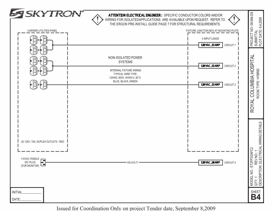
4 INPUT LEADS
B4SHEETINITIAL:
DATE:
DE
SC
RIP
TIO
N:E
LEC
TR
ICA
LW
IRIN
GD
ET
AIL
S
CARRIER UTILITIES PANEL FIXTURE JUNCTION BOX AT MOUNTING PLATE
110VAC FEMALE
IEC PLUG
(FOR MONITOR)H5-010-71
120 VAC, 15 AMP
120 VAC, 15 AMP CIRCUIT 1
CIRCUIT 2
120 VAC, 20 AMP CIRCUIT 4
(5) 125V, 15A, DUPLEX OUTLETS - RED
NON-ISOLATED POWER
SYSTEMS
INTERNAL FIXTURE WIRING
TYPICAL WIRE TYPE:
12AWG, 600V, XHHW-2, 90°C
BLUE, BLACK, GREEN
ATTENTION ELECTRICAL ENGINEER: SPECIFIC CONDUCTOR COLORS AND/OR
WIRING FOR ISOLATEDAPPLICATIONS ARE AVAILABLE UPON REQUEST. REFER TO
THE ERGON PRE-INSTALL GUIDE PAGE 7 FOR STRUCTURAL REQUIREMENTS.
MO
DE
LN
O.:
ET
2FP
3/2A
FC
2
QT
Y:1
RE
VN
O.:
1R
OY
AL
CO
LUM
BIA
HO
SP
ITA
LR
OO
MT
YP
E:H
YB
RID
PR
OJE
CT
NO
:09-
084-
DS
SU
BM
ITT
AL
PLO
TD
AT
E:9
.4.2
009
120 VAC, 15 AMP CIRCUIT 3
Issued for Coordination Only on project Tender date, September 8,2009
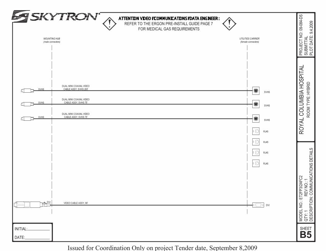
MOUNTING HUB
(male connectors)
RJ45
DUAL MINI COAXIAL VIDEO
CABLE ASSY, SVHS 75'SVHSSVHS
UTILITIES CARRIER
(female connectors)
DVI
DVI VIDEO CABLE ASSY, 66'
B5SHEETINITIAL:
DATE:
DE
SC
RIP
TIO
N:C
OM
MU
NIC
AT
ION
SD
ET
AIL
S
ATTENTION VIDEO / COMMUNICATIONS / DATA ENGINEER:REFER TO THE ERGON PRE-INSTALL GUIDE PAGE 7
FOR MEDICAL GAS REQUIREMENTS
MO
DE
LN
O.:
ET
2FP
3/2A
FC
2
QT
Y:1
RE
VN
O.:
1R
OY
AL
CO
LUM
BIA
HO
SP
ITA
LR
OO
MT
YP
E:H
YB
RID
RJ45
RJ45
RJ45
PR
OJE
CT
NO
:09-
084-
DS
SU
BM
ITT
AL
PLO
TD
AT
E:9
.4.2
009
DUAL MINI COAXIAL VIDEO
CABLE ASSY, SVHS 75'SVHSSVHS
DUAL MINI COAXIAL VIDEO
CABLE ASSY, SVHS 200'SVHSSVHS
Issued for Coordination Only on project Tender date, September 8,2009

MOMENT LOAD:FIXTURE WEIGHT:
0"
2900 HEIGHTCEILING
FLOOR 0"
367 kg 6215 Nm
C1SHEETINITIAL:
DATE:
DE
SC
RIP
TIO
N:E
LEV
AT
ION
VIE
W
RO
YA
LC
OLU
MB
IAH
OS
PIT
AL
RO
OM
TY
PE
:HY
BR
ID
ATTENTION STRUCTURAL ENGINEER:REFER TO THE ERGON PRE-INSTALL GUIDE PAGE 5
FOR STRUCTURAL REQUIREMENTS
72"
MO
DE
LN
O.:
EC
T2F
VB
/2A
FC
1/A
UR
5
QT
Y:1
RE
VN
O.:
2
75
250
800
1550
290
1300
900
450
550
482
800
1700
900
H9-200-21
72"
FLAT SCREEN MONITOR IS NOT PROVIDED
900
2032
REFER TO DATA SHEET
#AUR5 FOR SURGICAL LIGHT
SPECIFICATIONS
PR
OJE
CT
NO
:09-
084-
DS
SU
BM
ITT
AL
PLO
TD
AT
E:9
.4.2
009
Issued for Coordination Only on project Tender date, September 8,2009
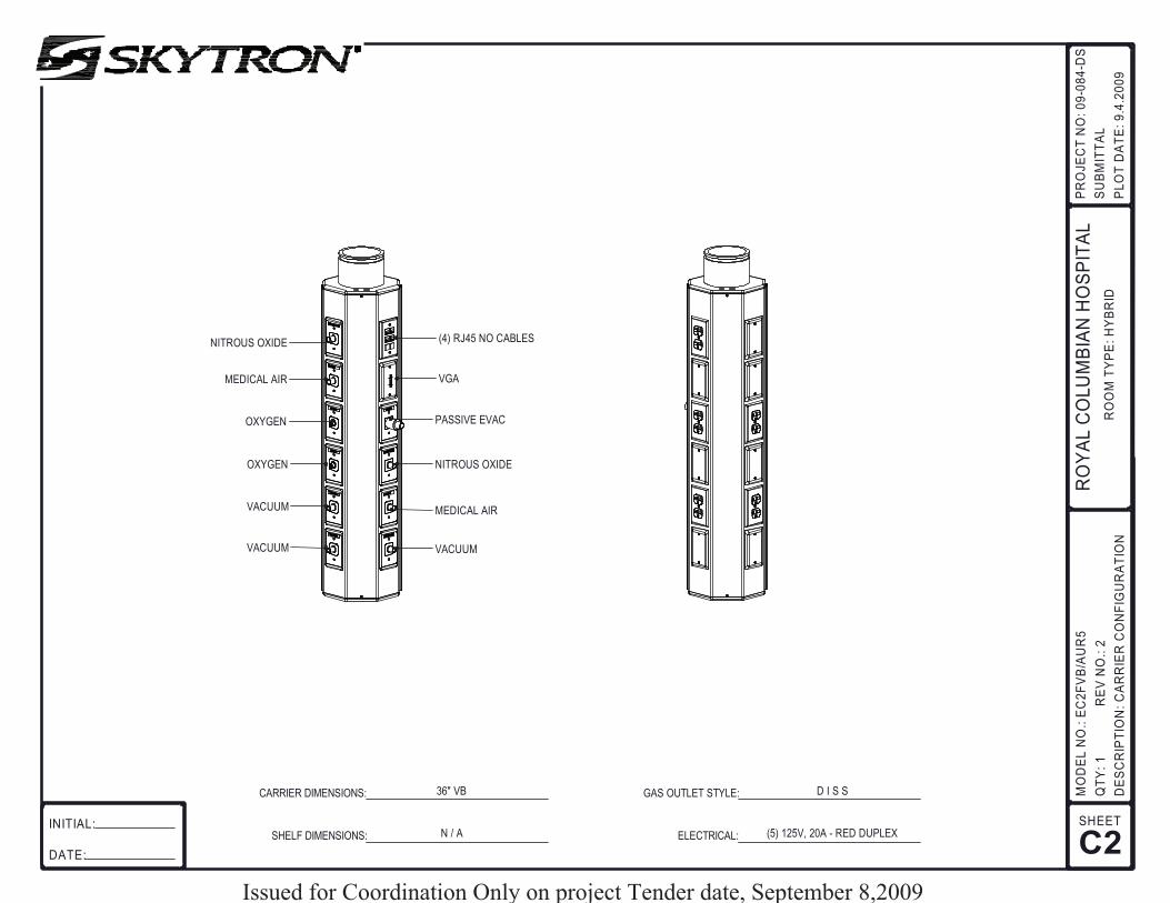
(5) 125V, 20A - RED DUPLEXN / A
D I S S36" VB
INITIAL:
CARRIER DIMENSIONS:
SHELF DIMENSIONS: ELECTRICAL:
GAS OUTLET STYLE:
C2
RO
YA
LC
OL
UM
BIA
NH
OS
PIT
AL
RO
OM
TY
PE
:H
YB
RID
DE
SC
RIP
TIO
N:
CA
RR
IER
CO
NF
IGU
RA
TIO
NP
LO
TD
AT
E:
9.4
.20
09
SHEET
SU
BM
ITT
AL
PR
OJE
CT
NO
:0
9-0
84
-DS
MO
DE
LN
O.:
EC
2F
VB
/AU
R5
QT
Y:
1R
EV
NO
.: 2
DATE:
MEDICAL AIR
VACUUMVACUUM
VACUUM
NITROUS OXIDEOXYGEN
VGAMEDICAL AIR
(4) RJ45 NO CABLES
OXYGEN PASSIVE EVAC
NITROUS OXIDE
Issued for Coordination Only on project Tender date, September 8,2009

RISER PLATE
*SUPPLIED w/MOUNTING KIT*
GAS CONNECTOR ASSEMBLY
(w/ SECONDARY CHECK)
*SUPPLIED w/FIXTURE*
9"
DISS CONNECTOR(w/ PRIMARY CHECK.
PASSIVE EVAC, VACUUM &
WAGD DO NOT HAVE
PRIMARY CHECK.)
*SUPPLIED w/MOUNTING KIT*
D I S S
CHEM
ETRO
N
VERIFY AND INITIALGAS FACEPLATE
STYLE REQUESTED
C3SHEETINITIAL:
DATE:
DE
SC
RIP
TIO
N:M
ED
ICA
LG
AS
DE
TA
ILS
CGA ColorStandard
Note #1 - Any room (Critical Care Area) designed for a permanenty located respiratory ventilator or anesthesia machine shall have an outlet capable of a transient flow rate of:
170 LPM (6 SCFM) for 3 seconds at the station outlet.
Note #2 - For testing and certification purposes, individual station inlets shall be capable of a flow rate of: 3 SCFM, while maintaining a system pressure of not less than 12"
(300mm) at the nearest adjacent vacuum inlet. Facility supply must be 115 LPM MINIMUM. (Vacuum D.I.S.S. connectors omit primary check valves for optimal flow).
12in/HG.
Note #3 - WAGD (Waste Anesthetic Gas Disposal) systems employing a design where the WAGD lines are "tied in" to MedVac lines must produce the same flow rates as the
MedVac inlets.
Note #4 - Nitrogen system requires nitrogen supplied directly from facility supply line rated at 185psi MIN to 200psi MAX.
Additional references: Health Care Facilities Handbook 2002, Section 5.1.11, page 211 and section 5.1.12.13.10.1 thru 5.1.12.3.10.5, page 224.
NFPA 99, 2002 guideline figure A.5.1.6.
• TYPE K COPPER
TUBING
• 1/2" O.D. UNLESS
OTHERWISE
STATED
Medical Air
(Yellow)
Test GasCanada ColorStandard
Medical Air
(Black)
AbbreviatedName
MedAir
StandardPressure
50 - 55 psig
MaximumPressure
55 psig
AllowablePressureDrop
5 psig
Minimum Flow Rates
3.5 SCFM per outlet (100NL/min)N2NF see note #1Carbon Dioxide
(Gray)
Carbon Dioxide
(Gray) CO2 50 - 55 psig 55 psig 5 psig 3.5 SCFM per outlet (100NL/min)N2NFHeliox
(Brown)
Heliox
(Brown) Heliox 50 - 55 psig 55 psig 5 psig 3.5 SCFM per outlet (100NL/min)N2NFNitrogen
(Black)
Nitrogen
(Black) N2 or HPN2 160 - 185 psig 200 psig 5 psig5 SCFM per outlet (140NL/min)
free air per outletN2NF see note #4Nitrous Oxide
(Blue)
Nitrous Oxide
(Blue) N2O 50 - 55 psig 55 psig 5 psig 3.5 SCFM per outlet (100NL/min)N2NFOxygen
(Green)
Oxygen
(White) O2 50 - 55 psig 55 psig 5 psig 3.5 SCFM per outlet (100NL/min)N2NF see note #1Vacuum
(White)
Vacuum
(Yellow) MedVac 12in/Hg (300mm) N/A 3 SCFM per outlet (85NL/min) see note #2Waste Anesthetic
Gas Disposal
(Purple) WAGD
Varies with
system type
At a minimum, each inlet must be able to
draw a continuous 50 lpm (1.8 SCFM)
through the interface
Waste Anesthetic
Gas Disposal
(Purple) see note #3
ATTENTION MEDICAL GAS / PIPINGENGINEER:REFER TO THE ERGON PRE-INSTALL GUIDE PAGE 7
FOR MEDICAL GAS REQUIREMENTS
PURIT
AN
OHME
DA
RO
YA
LC
OLU
MB
IAH
OS
PIT
AL
RO
OM
TY
PE
:HY
BR
ID
OX
YG
EN
OX
YG
EN
ME
DIC
AL
AIR
ME
DIC
AL
AIR
VA
CU
UM
VA
CU
UM
VA
CU
UM
MO
DE
LN
O.:
EC
T2F
VB
/2A
FC
1/A
UR
5
QT
Y:1
RE
VN
O.:
3
NIT
RO
US
OX
IDE
REQUIRES CUSTOM
RISER PLATE
PA
SS
IVE
EV
AC
3/4"
PR
OJE
CT
NO
:09-
084-
DS
SU
BM
ITT
AL
PLO
TD
AT
E:9
.4.2
009
NIT
RO
US
OX
IDE
Issued for Coordination Only on project Tender date, September 8,2009

6 INPUT LEADS
C4SHEETINITIAL:
DATE:
DE
SC
RIP
TIO
N:E
LEC
TR
ICA
LW
IRIN
GD
ET
AIL
S
CARRIER UTILITIES PANEL FIXTURE JUNCTION BOX AT MOUNTING PLATE
110VAC FEMALE
IEC PLUG
(FOR MONITOR)H5-010-71
120 VAC, 15 AMP CIRCUIT 1
120 VAC, 20 AMP CIRCUIT 6
(5) 125V, 15A, DUPLEX OUTLETS - RED
NON-ISOLATED POWER
SYSTEMS
INTERNAL FIXTURE WIRING
TYPICAL WIRE TYPE:
12AWG, 600V, XHHW-2, 90°C
BLUE, BLACK, GREEN
ATTENTION ELECTRICAL ENGINEER: SPECIFIC CONDUCTOR COLORS AND/OR
WIRING FOR ISOLATEDAPPLICATIONS ARE AVAILABLE UPON REQUEST. REFER TO
THE ERGON PRE-INSTALL GUIDE PAGE 7 FOR STRUCTURAL REQUIREMENTS.
RO
YA
LC
OLU
MB
IAH
OS
PIT
AL
RO
OM
TY
PE
:HY
BR
ID
MO
DE
LN
O.:
EC
T2F
VB
/2A
FC
1/A
UR
5
QT
Y:1
RE
VN
O.:
2
PR
OJE
CT
NO
:09-
084-
DS
SU
BM
ITT
AL
PLO
TD
AT
E:9
.4.2
009
120 VAC, 15 AMP CIRCUIT 2
120 VAC, 15 AMP CIRCUIT 4
120 VAC, 15 AMP CIRCUIT 5
120 VAC, 15 AMP CIRCUIT 3
Issued for Coordination Only on project Tender date, September 8,2009

MOUNTING HUB
(male connectors)
RJ45
SVGASVGA 5 CORE VIDEO CABLE ASSY, 15 PIN, 75'
UTILITIES CARRIER
(female connectors)
C5SHEETINITIAL:
DATE:
DE
SC
RIP
TIO
N:C
OM
MU
NIC
AT
ION
SD
ET
AIL
S
ATTENTION VIDEO / COMMUNICATIONS / DATA ENGINEER:REFER TO THE ERGON PRE-INSTALL GUIDE PAGE 7
FOR MEDICAL GAS REQUIREMENTS
RO
YA
LC
OLU
MB
IAH
OS
PIT
AL
RO
OM
TY
PE
:HY
BR
ID
RJ45
RJ45
RJ45
MO
DE
LN
O.:
EC
T2F
VB
/2A
FC
1/A
UR
5
QT
Y:1
RE
VN
O.:
3
PR
OJE
CT
NO
:09-
084-
DS
SU
BM
ITT
AL
PLO
TD
AT
E:9
.4.2
009
Issued for Coordination Only on project Tender date, September 8,2009
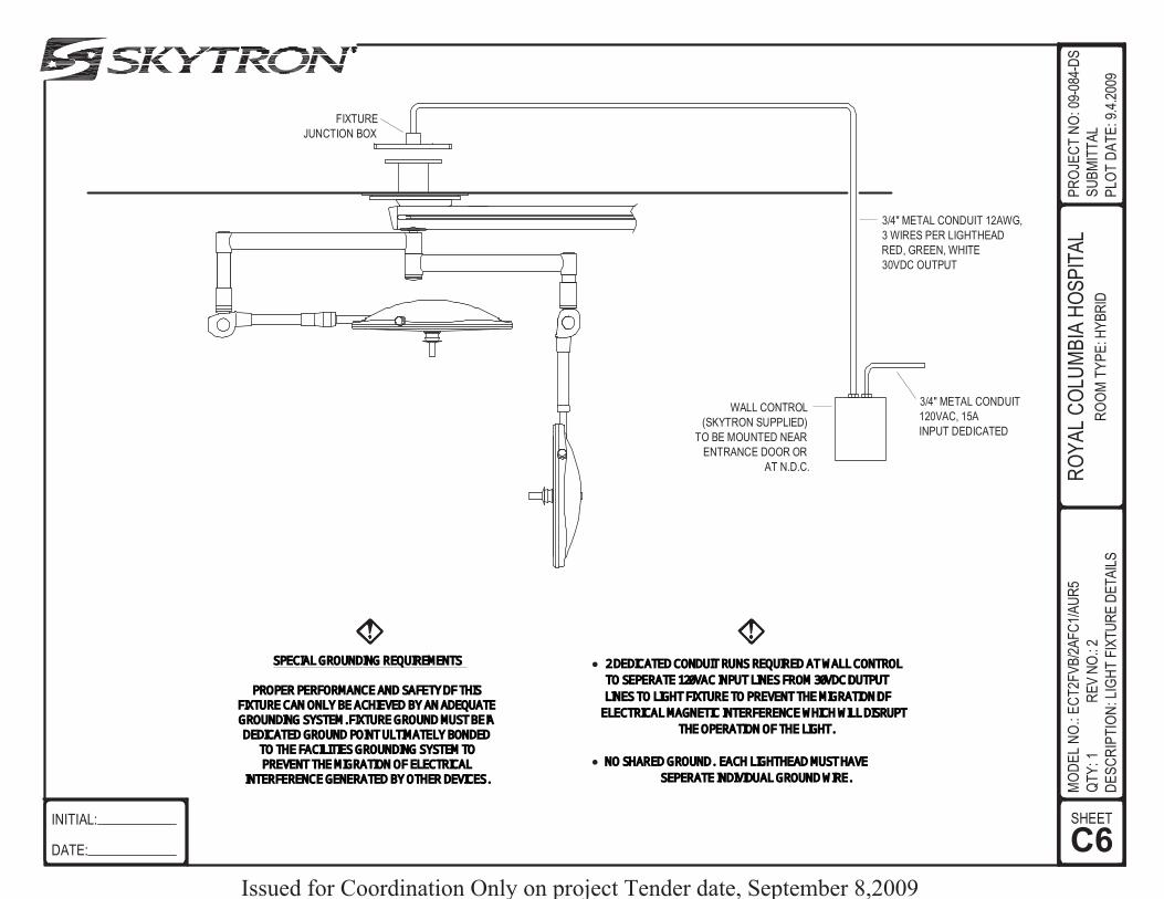
C6SHEET
DE
SC
RIP
TIO
N:L
IGH
TF
IXT
UR
ED
ET
AIL
S
INITIAL:
DATE:
FIXTURE
JUNCTION BOX
WALL CONTROL
(SKYTRON SUPPLIED)
TO BE MOUNTED NEAR
ENTRANCE DOOR OR
AT N.D.C.
3/4" METAL CONDUIT
120VAC, 15A
INPUT DEDICATED
3/4" METAL CONDUIT 12AWG,
3 WIRES PER LIGHTHEAD
RED, GREEN, WHITE
30VDC OUTPUT
SPECIAL GROUNDING REQUIREMENTS
PROPER PERFORMANCE AND SAFETY OF THISFIXTURE CAN ONLY BE ACHIEVED BY ANADEQUATEGROUNDING SYSTEM. FIXTURE GROUND MUST BE ADEDICATED GROUND POINT ULTIMATELY BONDED
TO THE FACILITIES GROUNDING SYSTEMTOPREVENT THEMIGRATION OF ELECTRICAL
INTERFERENCEGENERATED BY OTHER DEVICES.
● 2 DEDICATEDCONDUIT RUNS REQUIRED AT WALL CONTROL
TO SEPERATE 120VAC INPUT LINES FROM 30VDC OUTPUT
LINES TO LIGHT FIXTURE TO PREVENT THEMIGRATION OF
ELECTRICAL MAGNETIC INTERFERENCEWHICHWILL DISRUPT
THE OPERATION OF THE LIGHT.
● NO SHARED GROUND. EACH LIGHTHEAD MUSTHAVE
SEPERATE INDIVIDUAL GROUNDWIRE.
RO
YA
LC
OLU
MB
IAH
OS
PIT
AL
RO
OM
TY
PE
:HY
BR
ID
MO
DE
LN
O.:
EC
T2F
VB
/2A
FC
1/A
UR
5
QT
Y:1
RE
VN
O.:
2
PR
OJE
CT
NO
:09-
084-
DS
SU
BM
ITT
AL
PLO
TD
AT
E:9
.4.2
009
Issued for Coordination Only on project Tender date, September 8,2009

0"
2900 HEIGHTCEILING
FLOOR 0"
RO
YA
LC
OLU
MB
IAN
HO
SP
ITA
LP
RO
JEC
TN
O:0
9-08
4-D
S
SU
BM
ITT
AL
PLO
TD
AT
E:9
.4.2
009
72"
MO
DE
LN
O.:
AU
R5T
V5-
C-2
000/
1500
DE
SC
RIP
TIO
N:
AU
RO
RA
II L
IGH
TS
YS
TE
M
FIX
TU
RE
ELE
VA
TIO
NV
IEW
SIGNATURE:
DATE:
REFER TO DATA SHEET
#AUR55 FOR SURGICAL LIGHT
SPECIFICATIONS
2032
1500
2032
2000
CAMERA
D1SHEET
Issued for Coordination Only on project Tender date, September 8,2009

72"
FLOOR 0"
Refer to SKYTRON LFS spec book for
Mounting Structure construction.
MOMENT LOAD: 623 NmFIXTURE WEIGHT: 61 kg
2900 HEIGHTCEILING
E1SHEET
MO
DE
LN
O.:
LFS
X-R
AY
QT
Y:1
RE
VN
O.:
2
DE
SC
RIP
TIO
N:C
EIL
ING
HT
.ELE
VA
TIO
NV
IEW
INITIAL:
DATE:
RO
YA
LC
OLU
MB
IAH
OS
PIT
AL
RO
OM
TY
PE
:HY
BR
ID
PR
OJE
CT
NO
:09-
084-
DS
SU
BM
ITT
AL
PLO
TD
AT
E:9
.4.2
009
6"39.5"
50.6"43"
39.5"
24"
15"
3"
3"
24"
15"
3"
3"
Issued for Coordination Only on project Tender date, September 8,2009

72"
FLOOR 0"
Refer to SKYTRON LFS spec book for
Mounting Structure construction.
6"39.5"
50.6"
MOMENT LOAD: 623 NmFIXTURE WEIGHT: 61 kg
2900 HEIGHTCEILING
F1SHEET
MO
DE
LN
O.:
LFS
X-R
AY
QT
Y:1
RE
VN
O.:
2
DE
SC
RIP
TIO
N:C
EIL
ING
HT
.ELE
VA
TIO
NV
IEW
INITIAL:
DATE:
RO
YA
LC
OLU
MB
IAH
OS
PIT
AL
RO
OM
TY
PE
:HY
BR
ID
PR
OJE
CT
NO
:09-
084-
DS
SU
BM
ITT
AL
PLO
TD
AT
E:9
.4.2
009
10.6254.750
24"
15"
3"
3"
Issued for Coordination Only on project Tender date, September 8,2009

RE
V. 9
/08
Mountin
g S
tructu
re
PR
E-IN
STA
LL
AT
ION
GU
IDE
for E
rgon S
kyboom
s
Issued fo
r Coord
inatio
n O
nly
on p
roje
ct T
ender d
ate
, Septe
mber 8
,2009

Page 1
Skytron’s objective is to provide a program and guideline to assist individuals (hospital owners, architects, structural
engineers) responsible for the design of mounting structures.
The mounting structure of a Skytron fixture should always be considered the most important detail of any project prior
to installation. Skytron’s ceiling mounted systems depend upon properly designed and installed mounting structures
to deliver years of dependable, service-free performance.
We realize that individual mounting structures vary in design due to unique structural requirements, physical obstruc-
tions, structural member availability and room layout limitations, to name a few.
The mounting structure design in this Mounting Structure Guideline Booklet is a successful, proven design. The
design consists of a welded, “flanged tube” assembly combined with (4) angled sway braces (“kickers”). A structural
steel tube combined with welded steel plates on each end facilitate its attachment to the structural ceiling and provide
an attachment point for the Skytron fixture. This is a simple effective design that is forgiving to restricting structural
conditions that are usually encountered during fabrication.
This design also eliminates “guess work” by the steel fabricator when compared to structures that are fabricated on
site with angle iron. In many cases the “flanged tube” assembly can be pre-fabricated reducing the on-site construc-
tion time and eliminating the need to correct structural problems associated with angle iron structures.
The process of building a proper mounting structure can be complemented with Skytron’s continued support on the
project. Once the structures are fabricated, Skytron will perform a visual inspection and on-site consultation followed
by an actual performance test. The performance test of the structure essentially involves hanging a “test jig” from the
structure, and then measuring the amount of rotation that occurs at the mounting plate using an inclinometer (digital
level). The test jig is similar in size, shape, and weight to a Skyboom. In other words, once the test jig is installed and
the proper weights have been added to simulate the product’s moment load, a reading is taken on the digital level to
verify that there is no more that two-tenths of a degree of rotational movement at the mounting plate.
Rotation of the mounting plate causes the radial arm(s) to become out of level and drift. For a structure to meet
Skytron specifications, we require that the mounting plate does not rotate more that two-tenths of a degree while
loaded with the specified weight and moment.
The testing process should occur in the early stages of construction to provide optimal time if additional reinforcement
is needed on the structure. This should be performed prior to the completion of the finished ceiling.
Skytron’s program is available to help you and provide you with the necessary counseling. However, the final re-
sponsibility to insure that the structure is adequate and meets specification lies with the structural engineer and the
contractor for the project.
Our support services are geared to minimize the effort on all parties involved and to insure a successful product
installation.
This Mounting Structure is applicable for all SKYTRON Skyboom models.
We recognize that not all situations will permit the use of this “Tube Structure”. Please contact SKYTRON with your
special needs so that we may be able to guide you to other alternatives.
SKYTRON MOUNTING STRUCTURES
for Ceiling Mounted Equipment
Foreword
Issued for Coordination Only on project Tender date, September 8,2009

Page 2
INTRODUCTION
This publication is meant to provide the information needed to design and build a mounting structure that
will provide the proper support for a SKYTRON Skyboom fixture as well as the guidance for supplying
the necessary services. The responsibilities and items supplied by both SKYTRON and the Customer
for pre-installation of the fixture will vary depending on the equipment and services that will be provided
on the Skyboom fixture. The mounting structure requirements however, are the same for all models. The
structure design is based on the heaviest Skyboom model with the greatest moment load. By using this
criteria, one structure design can be utilized to minimize design costs and provide adequate support for
future modifications. If applicable, specific Seismic Calculations can be provided from SKYTRON. The
Mounting Structure design should always be approved by a Structural Engineer. An inadequate Mount-
ing Structure may allow drifting and other performance problems for the fixture. Equipment warranty or
service charges due to an inadequate Mounting Structure are at the customer’s expense. SKYTRON does
not warrant or certify superstructure designs.
This publication is intended to address various areas and responsibilities of multiple individuals. It is im-
portant that this information is shared with:
- Architects and Structural Engineer - Electrical Engineer
- Medical Gas/Piping Engineer - Communication/Video/Data Engineer
- Project Manager(s)
SKYTRON Supplied Components
SKYTRON supplies the following items to assist in the design and construction of the mounting struc-
ture:
Customer approved room layout and Skyboom configuration drawings.
Skyboom mounting plate
Medical gas riser plate with appropriate medical gas connectors
Electrical junction box
Fixture mounting hardware
Pump Enclosure (if applicable)
CUSTOMER Supplied Components and Responsibilities
Mounting Structure - Architect and Structural Engineer
The Customer is responsible for the design and fabrication of the structure which connects the SKYTRON
mounting plate to the structural ceiling. The mounting plate must be perfectly level (±0.1°). The design and
fabrication must include the necessary bracing to prevent twisting or lateral motion and to allow no more
than two-tenths of a degree (0.2°) of rotation at the mounting plate when the specified load is applied.
Refer to Page 5 for recommended specifications.
An inadequate mounting structure can result in damage to the equipment. Equipment warranty charges
related to an inadequate structure design or installation are at the customers expense. The mounting
structure design specifications included in this publication depict a successful, proven design. The actual
building design, additional loading required by local building codes and various obstacles may exist that do
not allow this design system to be followed. It is the customer’s responsibility to provide the appropriate
alternate mounting structure. SKYTRON recommends that a Structural Engineer be consulted whenever
a design variation is needed.
Issued for Coordination Only on project Tender date, September 8,2009

Page 3
Electrical Provisions - Electrical Engineer
Each Skyboom fixture is fabricated in accordance to the specifications required by the customer. The
customer is responsible for the appropriate electrical supply to the fixture. The Configuration drawings
supplied by SKYTRON will indicate the type and quantity of circuits required. The customer is responsible
for connections from facility supply to fixture, wall control and wiring installation for surgical lights and pump
motor connection if applicable.
Refer to Page 7 for Electrical Requirements.
Medical Gas Provisions - Medical Gas/Piping Engineer
Each Skyboom fixture is fabricated in accordance to the specifications required by the customer (to in-
clude the type of faceplate connectors to be provided on the fixture). The customer is responsible for the
appropriate medical gas supply and connection to the fixture. The Configuration drawings supplied by
SKYTRON will indicate the type and quantity of gas supply lines required.
Refer to Page 7 for Medical Gas Requirements.
Communications Provisions - Communication/Video/Data Engineer
Each Skyboom fixture is fabricated in accordance to the specifications required by the customer. The
customer is responsible for the appropriate communication cable routing to the fixture. The Configuration
drawings supplied by SKYTRON will indicate the type and quantity of cables required.
Refer to Page 7 for Communications Requirements.
Testing
NOTE
A visual review of the mounting structure construction should be requested before the finished
ceiling is installed to detect possible interference potentials, and arrangements can be made
to conduct a load simulation using a Test Jig. This process is designed to simulate the fixture
load and is an effective means to determine where the structure may require improvement. It
is not a certification of the structure.
The customer is responsible for the testing and any necessary certification requirements for all system
utilities prior to the installation of the Skyboom fixture. The testing and certification must be in accordance
with all state, federal, local, NFPA and NEC codes and must include the following items:
Mounting Structure (Testing performed by Skytron)
Electrical Wiring
Medical Gas Supply
INSTALLATION KIT
SKYTRON provides an installation kit which is typically shipped in advance and contains all of the Skytron
supplied components required for pre-installation and the fabrication of the Skyboom Mounting Structure.
The Installation Kit includes the following:
-Customer approved room layout and Skyboom configuration drawings.
-Mounting Plate
-Medical gas riser plate(s) with appropriate D.I.S.S. medical gas connectors
-Electrical junction box
-Mounting hardware for riser plate and junction box
Issued for Coordination Only on project Tender date, September 8,2009

Pag
e 4
030504.03mj_2
STR
UC
TU
RA
LC
EIL
ING
PLA
TE
17" D
IA x 1
"
10" (-0
"/+1")
12" M
IN / 6
0" M
AX
EX
PA
NS
ION
AN
CH
OR
S:
HILT
I KB
-II (ICB
O 4
627)
CA
RB
ON
STEEL
STR
UC
TU
RA
LC
EIL
ING
FIN
ISH
ED
CEIL
ING
STR
UC
TU
RA
LC
EIL
ING
MO
UN
TIN
G P
LA
TE
(SK
YTR
ON
SU
PP
LIE
D)
FIX
TU
RE H
UB
GU
SS
ET
6" D
IAS
UP
PO
RT
TU
BE
TY
P 1
/4"
TO
P &
BO
TTO
M
TY
P 1
/4"
PJP
45°- 60°
SW
AY
BR
AC
ING
3"x 3
"x 1/4
"(4
)
STR
UC
TU
RA
L C
ON
CR
ETE S
LA
BN
OR
MA
L W
EIG
HT
fc = 3
000 P
SI (2
0,6
84 kP
a)
20"
DIA
METER
OP
EN
ING
REQ
UIR
ED
(CEN
TER
ED
UN
DER
MO
UN
T)
AC
CES
S D
OO
R24" X
24"
(REQ
UIR
ED
)
*
*C
RIT
ICA
L D
IMEN
SIO
N
11” H
IGH
CLEA
R
SP
AC
E A
BO
VE
MO
UN
TIN
G P
LA
TE
REQ
UIR
ED
ON
3 S
IDES
FO
R
GA
S A
ND
ELEC
TR
ICA
L
CO
MP
ON
EN
T
INS
TA
LLA
TIO
N
NO
TE
: Typic
al d
imensio
ns s
how
n. R
efe
r to s
pecifi
c s
tructu
ral d
raw
ings a
nd/o
r Seis
mic
dra
win
gs fo
r each a
pplic
atio
n.
NO
TE
: This
illustra
tion d
epic
ts a
typic
al m
ountin
g s
tructu
re d
esig
n a
nd its
com
ponents
.
Alw
ays c
onsult s
pecifi
c s
tructu
ral c
riteria
defined b
y a
stru
ctu
ral e
ngin
eer.
NO
TE
: Do n
ot c
ove
r or b
lock a
ny h
ole
s w
ith sw
ay b
racin
g, g
ussets
, weld
, weld
sla
g o
r etc
.
17.5
0
1.0
0
9.0
0
1.5
0
Ø10.6
3
1.5
0
4.2
5
4.2
5
9.5
0
9.5
0
Ø1.0
0
1.0
0
+0.1
5- 0
.00
0.2
5
1.0
00.2
5
9.7
59.0
0
Ø6.0
0
4.2
5
4.2
5
R0.5
0
9.7
5(4
pla
ces)
(6 p
lac
es
)Ø
1.3
1
27
.5°
030504.0
2b
Issued fo
r Coord
inatio
n O
nly
on p
roje
ct T
ender d
ate
, Septe
mber 8
,2009

Page 5
STRUCTURAL REQUIREMENTS - Architect and Structural Engineer
MOUNTING STRUCTURE COMPONENTS
The fabrication of each mounting structure may be slightly different but they each require the same basic components
to ensure stability. Refer to the figure on page 4 for the relationship of these components.
Sway Bracing (by others)
Sway bracing is designed to rigidly affix the Mounting Plate to the structural ceiling. The primary purpose of Sway
Bracing is to eliminate sway, or lateral twisting and flexing of the mounting structure as it “reacts” to dynamic load
changes caused by moving the fixture radial arms. The sway bracing should be welded to the Mounting Plate and
extend away from the center of the mount. A minimum of four sway braces placed 90° apart and positioned at a
45° to 60° angle is recommended.
Minimum recommended material for sway bracing is 3” x 3” x 1/4” angle iron. It is recommended that in all ap-
plications that the sway bracing be fastened to the structural ceiling.
Structural Ceiling Plate (by others)
The Structural Ceiling Plate rigidly attaches the mount to the Structural Ceiling using structural anchors appropri-
ate for the ceiling construction. The Structural Ceiling Plate should be a minimum of, 1” ASTM A36 steel plate,17”
diameter with (6) 5/8” diameter holes for structural anchors and is fabricated by others.
Expansion Anchors
anchors must meet the following criteria:
1. Hydraulic Ram Method: The anchor should have no observable movement at the applicable test load. For wedge
and sleeve type anchors, a practical way to determine observable movement is that the washer under the nut be-
comes loose.
2. Torque Wrench Method (Wedge or Sleeve Type): The applicable test torque must be reached within one-half (1/2)
turn of the nut. Testing should occur no sooner than 24 hours after installation of anchors. If any anchor fails testing,
test all anchors until 20 consecutive anchors pass, then resume the initial testing frequency. Test equipment is to be
calibrated by an approved testing laboratory in accordance with standard recognized procedures.
Support Tube (by others)
The Support Tube required to attach the Mounting Plate to the Structural Ceiling Plate is ASTM 500 Grade B, 6”
diameter tube. Support Tube is to be welded to Structural Ceiling Plate and Mounting Plate. A minimum of 6 gussets
placed 60° apart should be welded to the support tube at the structural ceiling plate and the Mounting Plate.
Mounting Plate (Skytron supplied)
The 17.5” x 17.5” x 1” ASTM A36 steel Mounting Plate is a Skytron supplied item. The Support Tube and Sway
Bracing are welded to the Mounting Plate. The mounting plate contains the corresponding bolt pattern for attaching
the fixture and provides the mounting areas for the junction box and gas riser plates.
MOUNTING STRUCTURE DESIGN
Seismic structural applications may differ. Please contact your local SKYTRON distributor for specific calculations. The
Mounting Structure must be designed and fabricated to position the bottom of the SKYTRON Mounting Plate 10”
(-0”+1”) above the finished ceiling. This is a critical dimension in order to accommodate proper clearance required
for ceiling cover function. The mounting plate must be perfectly level (±0.1°) and allow no more than two-tenths of a
degree (0.2°) of rotation at the mounting plate when the specified load is applied. The Mounting Structure must
be tested for strength and stiffness prior to installation of the fixture. A Test Jig is available from SKYTRON that
includes all components and documentation required for performing an approved Mounting Structure test. Refer to
page 8 for testing procedures.
Please consult your SKYTRON representative during early stages of construction to facilitate this process.
The testing process is a required, documented function prior to closing of the finished ceiling.
Ceiling Requirements
A 24” x 24” access door must be mounted adjacent to the mounting structure for entry by service personnel
for service access.
SKYTRON provides a 24” diameter ceiling cover designed to cover a 20” diameter ceiling hole cutout.
Issued for Coordination Only on project Tender date, September 8,2009

Pag
e 6
NO
TE
: This
illustra
tion d
epic
ts a
typic
al m
ountin
g s
tructu
re d
esig
n a
nd its
com
ponents
. Alw
ays c
onsult s
pecifi
c s
tructu
ral c
riteria
defined b
y a
stru
c-
tura
l engin
eer.
Mountin
g b
olts
and n
uts
ship
ped w
ith fi
xtu
re.
030504.04rr
1-1/4" HE
X N
UT
(24)
1-1/4" TH
RE
AD
ED
RO
D (6)
BR
AC
KE
T
RIS
ER
PL
AT
E
INL
ET
TU
BE
SK
YB
OO
M F
IXT
UR
E
WE
LD
ED
MO
UN
T A
SS
EM
BLY
(SU
PP
LIE
D B
Y O
TH
ER
S)
JUN
CT
ION
BO
X
PU
MP
EN
CL
OS
UR
E18”L
x 6”W x 12”H
Issued fo
r Coord
inatio
n O
nly
on p
roje
ct T
ender d
ate
, Septe
mber 8
,2009

Page 7
Electrical Requirements - Electrical Engineer
Each Skyboom fixture is fabricated in accordance to the specifications required by the customer. The
Configuration drawings supplied by SKYTRON will indicate the type and quantity of circuits required.
SKYTRON provides all wiring and electrical materials for connection from fixture to junction box or pump
enclosure (if applicable). SKYTRON supplies either an electrical junction box to facilitate field wiring for
up to six circuits that is mounted on the mounting plate in the correct position OR if applicable, a hydraulic
pump enclosure/junction box (18”L x 6”W x 12”H) that is to be remote mounted within 24” of the mount-
ing structure (by contractor). The pump enclosure can be shipped with the Installation Kit upon request.
Typical wire type is 12AWG, 600V, XHHW-2. Each circuit requires a separate, properly circuit protected,
120 VAC, 60 Hz power supply line enclosed in rigid metal conduit. All electrical materials for connection
to SKYTRON supplied junction box or pump enclosure and installation labor for such materials to be pro-
vided by customer. All wiring and materials to be in accordance with federal, state and local codes. It is
the customers responsibility to meet conformity to NFPA and NEC standards with respect to the number
of receptacles provided in a patient care area. (Page 4 - Drawing Package)
Medical Gas Requirements - Medical Gas/Piping Engineer
NOTES: Medical gas riser plates comply with NFPA 99-2005 Edition
Cleanliness of gas outlets must be maintained through installation.
Purge gas lines and test at least 24 hrs. prior to installation.
Test results must be made available to SKYTRON for verification & comparison.
Each Skyboom fixture is fabricated in accordance to the specifications required by the customer. The Con-
figuration drawings supplied by SKYTRON will indicate the type and quantity of gas supply lines required.
D.I.S.S. connection medical grade hoses connect the fixture to the Riser Plate connectors. The customer
is responsible to deliver the appropriate medical gas from the facility supply to the Riser Plate connectors
and for the design of a medical gas system with adequate flow capacity capable of compensating for the
accumulative flow restrictions associated with conventional construction methods i.e. flex gas hoses.
SKYTRON provides medical gas riser plate(s) and the appropriate connectors for attachment to the
Mounting Plate. The Riser Plate attaches to the Mounting Plate and will accommodate up to 12 gas con-
nectors. The connectors are D.I.S.S. type medical gas connectors with single check valves and provide
a 1/2” copper tube for attachment to facility supply lines. Caps are provided with Vacuum & WAGD gas
connectors to facilitate testing procedures.
All connection and testing of Medical Gas Piping to be performed in accordance with NFPA 99-2005
Edition-5.1.6 requirements.
- Evacuation lines and fittings rated at 70-75 l/min (2.47-2.64scfm) at user connection point.
- Vacuum lines (WAGD) and fittings rated at 85 l/min (3 scfm), based on 115 l/min facility supply
- Nitrogen system requires Nitrogen supplied directly from facility supply at 185 psi minimum to 200 psi
maximum (if applicable). Avoid designs which feature multiple in-line Nitrogen control systems in order to
avoid loss of flow capability. (Page 3 - Drawing Package)
Recomended Gas Riser Placement - When mount is in center of room, Riser Plate should face head
end of room, when mount is near walls, Riser Plate should be adjacent to wall. If more than one Riser
Plate is required they should be placed next to each other.
Communications Requirements - Communication/Video/Data Engineer
Each Skyboom fixture is fabricated in accordance to the specifications required by the customer. The
Configuration drawings supplied by SKYTRON will indicate the type and quantity of cables required. The
customer is responsible for the appropriate communication cable routing to the fixture. Special arrange-
ments can be coordinated for custom cable sets to be installed at the time of installation. Contact your
SKYTRON representative. (Page 5 - Drawing Package)
ADDITIONAL SKYTRON SUPPLIED ITEMS
In addition to the installation kit as outlined on page 3, SKYTRON provides the following items:
(6) 1-1/4” x 10” Threaded Rods, (24) 1-1/4” Hex Nuts, Pump Enclosure (if applicable)
Issued for Coordination Only on project Tender date, September 8,2009

Page 8
TESTING - MOUNTING STRUCTURE
Each mounting structure must be tested by a SKYTRON representative to verify that there is no more
than two-tenths of a degree of rotational movement at the mounting plate prior to installing a fixture. A
Mounting Structure Test Jig is available from SKYTRON to facilitate this process. The Mounting Structure
Test Jig is a fixture which simulates the weights and moment loads created by the SKYTRON fixture. It
consists of a Hub Assembly, an Upper and Lower Radial Arm, a Chain Fall, Weight Support Tube and six
100lbs. weights (refer to illustration on page 9).
The Drawing Package and the Test Jig Instructions are required to perform an acurate test.
The Test Jig Instructions include the Load Simulator Weight Chart, the Test Jig Report Form and complete
instructions for performing the test.
RECOMMENDED TOOLS
Issued for Coordination Only on project Tender date, September 8,2009

Pag
e 9
WE
IGH
T
SU
PP
OR
T T
UB
E
3/8
”
HIT
CH
PIN
CH
AIN
CH
AIN
FA
LL
CH
AIN
LO
WE
R R
AD
IAL A
RM
UP
PE
R R
AD
IAL A
RM
WE
IGH
TS
(6)
MO
UN
TIN
G H
UB
AS
SY.
12m
m N
UT
(6)
12 m
m x
30m
m B
OLT
(4)
12m
m N
UT
(4)
5/8
” NU
T (2
)
1-1
/4” T
HR
EA
DE
D
RO
D (6
)
1-1
/4” N
UT
S
SK
YT
RO
N M
OU
NT
ING
ST
RU
CT
UR
E T
ES
T J
IG
Issued fo
r Coord
inatio
n O
nly
on p
roje
ct T
ender d
ate
, Septe
mber 8
,2009

50
85
Co
rpo
rate
Exch
an
ge
Blvd
.S.E
. Gra
nd
Ra
pid
s, MI 4
95
12
comm/sky/skyboom/mounting/mounting guide/ergon pre-install guide 9-08
Issued fo
r Coord
inatio
n O
nly
on p
roje
ct T
ender d
ate
, Septe
mber 8
,2009