
Electrical Switchgear
50
Keeping electrical switchgear safe HSG230 HSE BOOKS
-
Upload
gusti-prasetyo-rendy-anggara -
Category
Documents
-
view
61 -
download
1
description
semua tentang electrical swithgear
Transcript of Electrical Switchgear
Keeping electrical switchgear safe
HSG230
HSE BOOKS
© Crown copyright 2002
First published 2002
ISBN 0 7176 2359 9
All rights reserved. No part of this publication may be reproduced, stored in a retrieval system, or transmitted in any form or by any means (electronic, mechanical, photocopying, recording or otherwise) without the prior written permission of the copyright owner.
Applications for reproduction should be madein writing to: Licensing Division, Her Majesty’s Stationery Office,St Clements House, 2-16 Colegate,NorwichNR31BQor by e-mail to:[email protected]
This guidance is issued by the Health and Safety Executive. Following the guidance is not
compulsory and you are free to take other action. But if you do follow the guidance you
will normally be doing enough to comply with the law Health and safety inspectors seek to
secure compliance with the law and may refer to this guidance as illustrating good practice.
ii
Contents1... Introduction1... Scope 23... Frequency ofmaintenance1... Background1... Legislation 24... Insulating oil
2... Equipment and its location
2... Potential problems with
22...Maintenance procedures
23...Oil circuit-breakers subject to special duty
24... Cleaning and inspection ofoil-filled
25... Tankcleaning techniques 26... Post-faultmaintenance ofoilcircuit-breakers
chambers
switchgear3... Lack of knowledge3... Overstressing
16... Care and maintenance ofnon-oil switchgear
3... Modifications 16...General advice4... Dependent manual operating mechanisms 17...Inspection4... Lack of maintenance 17...Maintenance4... Anti-reflexhandles 17...Maintenance procedures
5... Management of switchgear 18... Vacuum switchgear
5... Records 18... Frequency of maintenance5... Network diagrams5... Asset register safety precautions6... Maintenance records 19... Release of sulphur hexafluoride
6... Operational issues 20... Sampling6... Fault levels and ratings 20... Topping up7... Effect of on-site generation and other
17...
18... Air-break switchgear
19... Sulphur hexafluoride gas handling and
Sulphur hexafluoride switchgear
19... Hazards
large rotatingmachines7... Precautions for reducing the risk of
21... Care and maintenance ofancillary equipment
switchgear failure and injury 21... Testprobes8... Overstressed switchgear 21... Earthing equipment 8...
9... Modifications 22... Tests to beundertaken during 9... Fault clearance . commissioning
10... Care and maintenance of
10... General advice
Dependent manually operated (DMO) switchgear 22... Testing
22... Tests to be undertaken during and following maintenance
oil switchgear 22... Diagnostic testing
10... Inspection10... Switchgearenvironment switchgear
22... Assessment of aged
11...11. ...
11... Maintenance11... Time-based preventive maintenance procedures11... Condition-based maintenance 12... Reliability-centred maintenance (RCM)
Signs of abnormal condition Switchgear general condition
23...Assessment process overview 23... Phase 1-Initialconsiderations24... Phase 2-Condition assessment
24... Phase3-Informationassessment25... Phase 4-Review and decision
iii
25...Condition monitoring 29...Measures to limit fires25... Available techniques25... Partial discharge detection 29... Control and extinction 25... Thermographic surveys 30... Prevention26... Mechanism timing tests 30... Detection26... Strategiesfor application
29... Compartnentation
30... Safety issues
26...Protection 30...Training26...Protection relay schemes27... Fuseprotection
30...General advice31... Operational safetydocuments31... Inspection and maintenance
27... Batteries and chargers
27... Selection of new, 31... Insulating oil32...Capacitors32... Sulphur hexafluoride switchgear
replacement or refurbishedswitchgear
27...General advice
28... Replacement installations 28...Refurbished/retrofitted switchgear 29... Refurbishment ofswitchgear29... Retrofit circuit-breakers for
29... Second-handequipment
28...Ratings Appendices34...A Technicaldefinitions36... B Further reading38... C Examples ofswitchgear configurations 46... D Other sources o f information
withdrawable switchgear
iv
31 Disposable Issues
serious injury and major damage to plant and
buildings in the vicinity of the failed equipment.
6 Modern switchgear using sulphur
hexafluoride gas or vacuum as the insulating
medium has removed the hazard of burning oil
but inevitably has introduced other risks that
need to be managed. Accident experience has
shown that failure usually occurs at, or shortly
after, operation of the equipment. So the way
switchgear is operated, its condition and the circumstances existing in the system at the time of operation to a large extent determine whether the equipment will function safely.
7
manufactured in accordance with British and international standards for over 60 years. As
with most equipment, current specifications bear
little resemblance to those of earlier years and
the previous specifications have been shown, by
subsequent experience and by technical
developments, to be deficient. Examples of differing requirements between earlier and
current standards are those relating to operating
mechanisms and fault test sequences.
Introduction
1
and operators of electrical switchgear in
industrial or commercial organisations.
Electricity distribution companies or equipment suppliers may also find the advice useful. It
should help managers, engineers and other
relevant personnel understand their responsibilities and duties in the selection, use,
care and maintenance of high-voltage and low-
voltage switchgear.
2not be directly applicable and for interpretation any queries should be directed to the
appropriate enforcing authority. Definitions of
some of the key terms used in the book are
provided in Appendix A.
This book is aimed primarily at owners
In some circumstances the guidance may
Switchgear of all types and ratings has been
Scope
3 This book provides guidance on the selection, use, care and maintenance of three-
phase electrical switchgear with voltage ratings from 400 V alternating current (ac) up to and including 33 kV ac. It deals with circuit-breakers,
switches, switch fuses, isolators and high-voltage (HV) contactors. The types covered embrace switchgear using oil, air, sulphur hexafluoride
(SF,) or vacuum as the interrupting medium.
4 The guidance does not address direct
current (dc) switchgear, switchgear used on single-phase ac traction systems of any voltage, low-voltage moulded case circuit-breakers,
or low-voltage contactors and miniature 9 The HSW Act contains requirements
circuit-breakers.
Legislation
81974 (HSW Act), the Management of Health
and Safety at Work Regulations 1999
(Management Regulations) and the Electricity at Work Regulations 1989 (EAW Regulations)
apply (see Appendix B ‘Further reading’).
The Health and Safety at Work etc Act
to the effect that anyone employing people should ensure their safety so far as is reasonably
practicable.Background
5 In general, switchgear has a proven record 10 The Management Regulations require an of reliability and performance. Failures are rare employer (or self-employed person) to make an but where they occur the results may be assessment of risks to employees or others, taking catastrophic. Tanks may rupture and, in the case specialist advice where necessary. The level of of oil-filled switchgear, can result in the ejection detail in the assessment should be broadly of burning oil and gas clouds, causing death or proportionate to the risk, whch means it needs
1
to be fairly detailed in the case of switchgear as the risk is one of serious injury or even death.
11 The EAW Regulations require electrical 15 In some premises, low-voltage switchgear
equipment for use at work to be constructed, will be located in work activity areas. There will maintained and operated in such a way as also be cases where high-voltage switchgear and to prevent danger so far as is reasonably motor starters are found adjacent to the practicable. machinery that they control. It is important that
the equipment is in good condition. Operatives 12 in the area should be made aware of this and its strength and capability may be exceeded and procedures put in place for them to report
it should be protected from excess current. This incidents and/or any damage that occurs. is discussed in paragraphs 22 and 23 (see also
EAW Regulations, regulation 5). 16 Occasionally switchgear is located
place to detect and rectify such faults as
quickly as possible.
Equipment should not to be used where
outdoors. This can lead to even fewer visits than
to switchgear located in switchrooms and again a practice of periodic inspection is necessary, along with procedures to deal with any deterioration that is found.
Equipment and its location
13
supply, that incoming supply often passes
through switchgear to control dstribution of
electricity within the site. Switchgear varies in
size, age and appearance. Typical examples are
shown in Appendix C. It is important to recognise that the different categories of
switchgear, ie switches, isolators, switch fuses, HV contactors and circuit-breakers, have a
different switching capability and you need to
be familiar with the switchgear types on the site and their purpose.
14 Switchgear is generally located in
substations and/or switchrooms, ie areas that
are separated from the day-to-day activity of
are visited on a very infrequent basis. Such
rooms are generally locked and access is usually restricted to authorised persons.
Periodic inspection of switchrooms is
considered good practice to ensure that deterioration is not occurring to either the
switchgear or the environment. For example, it is unacceptable for any building damage to cause water or debris build-up on equipment that is for indoor use. Procedures should be in
In any premises that require a high-voltage 17 Much of the equipment still in service is some 25 years old or more. Equipment that is
35 or more years old is usually of particularly
robust construction. As a result, it is often
assumed (incorrectly) that the equipment has an
unlimited life in service. Much of the older
equipment has a limited operation capability
and these limitations are not always understood by operating staff. An example of this is a situation where a defined delay before operation
is necessary after a fault clearance to allow time
for the arc extinction processes to recover.
Potential problems with switchgear the premises and which, in many instances,
18 This section highlights a number of potential problems that may be encountered
with switchgear. These are particularly relevant
to oil-filled electrical switchgear that is more
than 25 years old but may well be valid for
more modern switchgear, depending on the circumstances of a specific user or site. The following sub-sections provide guidance on dealing with the relevant issues.
2
the resulting electrical and thermal stress that can sometimes lead to catastrophic failure, ie total destruction of the switchgear. Such failures are accompanied by arc discharge products, burning gas clouds and oil mist (if oil switchgear). These envelop anyone near the switchgear, resulting in serious burn injuries and often death.
Lack of knowledge
19staff, who are often known as ‘authorised persons’. In the past these were generally works’ electrical engineers and senior supervisors but due to changing employment patterns this is no longer the case. Some users may not have any ‘authorised persons’ on their staff and may have chosen to contract out all operational work and maintenance of their switchgear. As a result, there may be no one within the organisation who understands the equipment, its safe operation or the need for maintenance. This should be treated as unacceptable and steps should be taken to remedy the situation.
20maintenance of switchgear should receive
training (or refresher courses) relevant to the duties that are required of them. This is particularly relevant to staff called upon to operate switchgear and such staff should have competency at the ‘authorised person’ level. Even where all operational and maintenance work is contracted out, it is preferable that there is sufficient technical knowledge within the company to audit the practices of the 24 Over the years, manufacturers have issued. contractors and to handle abnormal (including emergency) situations that will inevitably arise on the premises. If this is not the case, this role should be given to an independent organisation.
21distribution companies or specialist training organisations) provide training courses to the varying levels of competency that may be required.
Switchgear should be operated by trained
23have been adequate, modfications and extensions to the network that feeds the switchgear, or of the network controlled by it, can lead to situations where the switchgear is overstressed. An example is where the infeed capacity has been increased. Also some configurations of the network (eg by paralleling of transformers onto the switchgear busbars) can lead to an overstressing situation. Such situations should be documented and clear operating instructions provided to prevent such a configuration being created. They can result from a response to an abnormal operational situation whereby an incorrect network configuration is inadvertently set up.
While the original installation design may
Staff responsible for care, operation and
Modifications
details of modifications to existing equipment that should be carried out on switchgear to improve its safety However, the procedures for circulating such information are not perfect and in many cases users are unaware of the need to carry out these modifications. As a result, the equipment may be incapable of performing satisfactorily. It would be wise to carry out an audit, if one has not already been undertaken, of the switchgear for which the user is responsible and liaise with the manufacturers (or other appropriate expert) to identify any outstanding modifications.
25circulars or instructions that are received relating to modifications and make them readily available to all staff whose duties involve the operation and maintenance of switchgear.
A number of organisations (eg electricity
Overstressing
22‘overstressed’ when the potential fault energy of the electrical system (eg from a short-circuit) at the switchgear location exceeds the fault energy rating of the switchgear. When it is operated under fault conditions it is unable to cope with
Switchgear is described as being It is also good practice to catalogue any
3
contact refurbishment, and verification of
contact engagement may not have been carried
out for many years and deterioration due to
corrosion may also have occurred. In some
cases the expertise in maintenance techniques
and for handling insulating oil is lacking.
29 Where oil-filled switchgear has been
neglected, it is difficult to. assess the actual fault capability of the switchgear in the state in which it is found. An audit of maintenance records
should be carried out to establish whether or not there is a problem and, if necessary, a detailed condition assessment should be made.
Dependent manual operating mechanisms
26 The operating mechanisms of most
switchgear, ie independent manual, dependent power, independent power and stored energy
(see Appendix A for definitions), do not result
in any particular risks. However, this is not the case where switchgear is of the dependent
manually operated (DMO) type. DMO mechanisms were fitted to both high- and low-
voltage switchgear but these types of operating mechanism are no longer made.
27
or opens the switchgear solely by manual effort.
Therefore movement of the contacts is totally
dependent upon the speed and actions of the
person operating the levers/ handles. Any hesitancy
on the part of the operator is likely to lead to a
serious and potentially fatal failure of the switchgear, eg operators may not realise that they
have failed to close the circuit-breaker completely
and release the operating lever/handle, thus
drawing an arc within the oil tank which can result in catastrophic failure. It is essential that these levers/handles are operated in a decisive and positive manner without any hesitation and as
rapidly as possible, particularly over the latter portion of the closing operation. In addition,
should a lever/handle be closed onto a system fault the force needed is significantly greater than when closed onto normal system load current. In
some cases it may be physically impossible to close
(or open) the device under fault conditions, again
this may result in failure. See paragraphs 54-58
for guidance on actions to take in these situations.
With DMO switchgear, the operator closes
Anti-reflex handles
30accident/incidents with high-voltage switches
was when an operator carried out an incorrect
operation when moving the operating handle (eg switching from OFF to EARTH instead of
from OFF to ON) and then immediately
attempted to reverse that incorrect operation.
As oil switches are not rated for the interruption of fault current, any attempt to open them when fault current is flowing is likely to lead to
disruptive failure, with the possibility of the
operator(s) being killed.
31 To address this problem, many manufacturers have produced anti-reflex operating handles for their equipment. These
handles are one-way operating devices and have
to be removed and relocated before carrying
out a further operation, thus imposing a time
delay between operations. This built-in time delay means that when the incorrect operation
is reversed, no fault current is flowing (as the circuit protection will have operated to
interrupt the current flow), and there is no likely failure of the switch. The built-in time
delay is also important when closing from OFF to ON onto a known fault.
At one time, a common cause of
Lack of maintenance
28 This is usually the result of oversight, lack
of knowledge of the equipment, or pressures to avoid plant shutdowns. Whatever the cause, it
will lead to a situation where switchgear has been neglected (this is particularly true of low- voltage devices). The result is that routine
servicing such as oil changing, lubrication,
32fuses should be undertaken to determine
A review of the oil switches and oil switch
4
whether an anti-reflex facility exists. Where no
such facility exists, action should be taken to retrofit an appropriate modification. switchgear;
switchgear.
The British Electrotechnical and Allied
(c) switchgear maintenance companies with
particular expertise in older types of
(d) consulting organisations specialising in
Management of switchgear Manufacturers Association (BEAMA) can
33 It is the duty of all users of switchgear to provide management systems that will ensure
safe operation and minimise the risk of injury,
Such management systems should include the following: for their addresses).
(a)
36
provide up-to-date details of manufacturers and
the Institution of Electrical Engineers (President’s list of experts) may also be able to
provide help and guidance as to other sources
of information and expertise (see Appendix D
policies and procedures covering the installation, commissioning, operation,
maintenance and removal of the equipment;
an appropriate system of records;
definition of responsibilities and training
requirements;auditing of the effectiveness of procedures.
An important pre-requisite is to identify all
Records(b)
(c)
(d)
37 All switchgear users should have a record of their switchgear available. Where there are
doubts about the accuracy or validity of records then a new inventory should be prepared as a matter of urgency. The basic records that are suggested are discussed below
34switchgear in service and to ensure that up-to-
date records of network diagrams and
values at every relevant point on the system) are
available. From this basic information, any potential risks, eg overstressing or dependent
manual operation, should be assessed so that
any necessary remedial action can be identified to ensure that the equipment and systems are being operated safely, and that work is put in
hand to eliminate or reduce the risks. The basic records for an LV installation may also contain electrical installation certificates and periodic inspection reports. Further information is in
BS 7671 (see Appendix B ‘Further reading’).
35 Sufficient technical expertise may not be
and decide on the appropriate precautions. In such cases switchgear users should take advice from suitably competent organisations, including: (a) electricity distribution companies;
(b) switchgear manufacturers;
configurations (including prospective fault level Network diagrams
38 The diagram is a schematic representation of the network and it is ideal to display the
interconnection of the plant items, including the
switchgear. This allows the normal and any alternative arrangements of the network to be
displayed in a way that is readily understood, bearing in mind that there may be several
switchrooms or substations on any one site. In
addition, the diagrams can be annotated with the status of the switchgear in a particular network
arrangement to avoid any confusion, particularly where overstressing may be an issue.
available in-house to carry out a risk assessment Asset register
39 An asset register forms the basis of management information providing both basic identification information (location, type etc)
and performance/maintenance records. Although some items may not be scheduled to
5
receive any routine maintenance, all items that
are likely to receive some kind of attention
during their life should be included.
A hierarchical structure is essential to ensure a
logical approach to establishing information for asset management purposes. It is possible to develop complex hierarchies, but most asset owners find that a two- or three-level
hierarchy is sufficient. A typical structure
might involve:
Level 1: Location/cost centre/process or production grouping Equipment associated with an activity,
eg production department.
Level 2: Unit Collection of plant items that are interdependent
and adjacent to each other in Level 1.
Level 3: Item Distinct item of plant within the unit, usually
the smallest discrete piece of equipment from an operational point of view, eg item of switchgear,
tripping battery etc.
40straightforward development of an asset numbering system, eg an item can be coded as a
combination of the cost centre code, the unit
code and its own code to provide a unique code.
41 Along with the structure, the level of information to be recorded against each item
needs to be decided. Collecting plant data can be a time-consuming and costly exercise,
particularly basic data that does not directly contribute to improvements in performance and
much basic data and typical information that is required for an item of switchgear at each location includes:
(a)
(b) manufacturer and type reference; (c) serial number and year of manufacture; (a) Identify the British Standards or other
(d) date of installation; standards relevant to the individual
(e) voltage rating; switchgear. (4 current rating; (b) Calculate fault energy levels at the output
6
(g)
(h)
fault rating and whether it is a certified or
assessed and assigned rating;
type of operating mechanism (dependent
manual, independent manual, dependent
power, independent power and stored
energy);details of any modifications, eg fitted anti- reflex handles; if the equipment is an oil circuit-breaker,
whether it is plain break equipment (ie equipment without arc control devices)
or not; type of electrical protection fitted and details of the settings.
(i)
(j)
(k)
Maintenance records
42
(a)
(b)
A minimum requirement would be to record: the date of the last maintenance/oil change
(where applicable); in the case of a circuit-breaker, the number
of fault operations since it was last
maintained (if known).
43 This provides a record that maintenance schedules are being adhered to and also provides planning for the next maintenance. As will beseen in later sections, some measurements are
taken during the maintenance and it is valuable
to record such data in order to determine trends
in performance and what problems are
emerging. Such records should be retained as a
history and the information should not
overwrite the previous record.
Use of a hierarchical structure allows the
safety. Care should be taken not to collect too Operational issues
Fault level and ratings
location (may already be defined by the
structure);
44
the site inventory (in particular the DMO switchgear) you need to take the following steps:
For each item of switchgear identified in
terminals of each item of switchgear. In
some cases it will be necessary to include the fault energy contribution from rotating plant such as large induction motors,
synchronous motors and generators. The
electricity supply company is required to provide, on request, the maximum short-
circuit current at the incoming supply
terminals (Electricity Supply Regulations
1988 regulation 32 or Electricity Safety, Reliability and Continuity Regulations (b) Provide measurement equipment to ensure
2002, regulation 27).
switchgear is in use that was designed to
obsolete British Standards (see Appendix B), reassessment of the rating by manufacturers
orspecialists may be necessary.
in (a) with the certified or assigned switchgear fault energy rating determined
in (c) to establish whether the equipment
is overstressed.
It is recommended that the procedures are
(a) Check that the fault energy levels at the circuit-breaker(s) controlling the
generators and other large rotating machines are within the capability of the
circuit-breaker, paying particular attention
to older switchgear. If this is not the case,
then treat the circuit-breaker as
overstressed. (The review of fault levels
discussed in the previous section should
have included the on-site generation.)
that generator or synchronous motors are
controlling circuit-breaker(.$, since attempting to close a circuit-breaker or
switch onto networks that are not synchronised can lead to overstressing.
recovery voltage across the controlling circuit-breaker(s) when opening on a fault
being fed by the generator and other large rotating machines. If this exceeds the
rating of the circuit-breaker(s), then treat
the circuit-breakers as overstressed. A problem that may arise with older
switchgear is relating the original test requirements for establishing rating against
the conditions on-site. In these cases
expert advice should be sought. Confirm whether the protection settings in use are appropriate for the situations when the generation is operating and when it is not operating. For guidance
refer to Electricity Association Engineering Recommendations G59/1,1991 and
(c) Determine the switchgear rating. Where synchronised before closing the
(d) Compare the fault energy levels calculated (c) Estimate the effects on the transient
45applied to both high-voltage (ie 3.3 ky 6.6 ky 11 ky 22 kV and 33 kv) systems and low- voltage (230/415 V) systems as separate exercises.
It may be easier to deal with each individual system at each voltage separately as the individual
system may have very different problems.
46 Other than for the simplest of system
configurations, the calculation of fault levels is a
specialist topic requiring support from people experienced in undertaking and interpreting such calculations. G75,1996.
(d)
Effect of on-site generation and other large rotating machines of switchgear failure and injury
Precautions for reducing the risk
47rotating machines have an impact on the
operational duty of switchgear, especially in terms of fault current handling, connection of the generators and synchronous motor drives to the network and on the protection requirements. The following actions need to be taken:
On-site generating plant and other large 48how quickly they should be implemented will
depend on whether the equipment is overstressed, whether it has been modified in accordance with manufacturer’s instructions,
the type of operating mechanism, the maintenance condition etc.
The need for precautions to be taken and
7
Overstressed switchgear 49 Where the switchgear fault energy rating
is less than the potential fault energy levels, the following actions should be taken immediately,
regardless of the type of operating mechanism:
(a) Prohibit all live operation and disable automatic tripping of the switchgear. This
action will necessitate readjustment of
electrical protection further back towards
the source of supply so that the electrical
protection at the switchgear can be made
non-operative. The readjustment is needed
to ensure adequate levels of electrical protection for the system.
Prevent people gaining access to the switchgear while it is live.
accordance with manufacturer’s advice by trained personnel. Particular attention should be paid to insulating oil, solid
insulation, contact assemblies, operating mechanisms, seals and gaskets, as applicable.
In some cases changing system operating conditions will achieve this, for example
operating transformers as single feeders to
51 If the actions (d) and (e) in paragraph 49 do not reduce the fault energy levels below the
ratings of the switchgear, and it is sited in open
workshop areas, the provision of blast protection should be considered. This may take the form of suitable walls or enclosures, the purpose of which is to contain any failure of the
switchgear while it is energised. However, this is
a complex matter and it is often more
practicable to make the switchgear dead and
provide alternative electrical supplies.
52 Where high-voltage and low-voltage
switchgear share the same switchroom and only
(b) one set of switchgear is overstressed, it will be necessary to either:
(c) The switchgear should be maintained in (a) keep personnel out until the overstressed switchgear is made dead; or
where space permits, erect a suitable blast wall around that switchgear, thus permitting
personnel access to the other switchgear.
(d) Reduce the fault energy levels, if possible. 53 In addition to these immediate actions, arrangements should be made to replace the
overstressed switchgear as soon as possible.
(b)
switchboards and not in parallel with other transformers. These changes should
Dependent manually operated (DMO) switchgear
be made as soon as possible to reduce the fault energy level to as low as practicable.
Longer-term measures that can be taken to
reduce fault energy levels include fitting reactors or network reconfiguration. These measures may be used to reduce fault energy levels to values less than the fault energy ratings of switchgear. Such
actions are normally only a solution for high-voltage installations. It should be
noted these measures will not overcome
the problems associated with switchgear that has no fault energy rating.
Where the actions (d) and (e) above reduce
54 Dependent manually operated (DMO) mechanisms are generally only found on older
types of oil and air circuit-breakers.
55switchgear should be restricted to those personnel trained in the operation of the switchgear concerned. They should also be aware of the
dangers of operating the equipment incorrectly, the construction of the switchgear and the
manufacturer’s maintenance requirements. The personnel will need to be familiar with the safe
system of work outlined in paragraph 56. It is essential that the actions listed to allow
continued use of DMO switchgear be treated
as short-term measures only.
56(ie ratings are greater than the actual fault energy levels), the following precautions are
(e)
All operation and maintenance of DMO
50
the fault energy levels below the rating of the
switchgear, then electrical protection and live
operation can be restored, after necessary
measures (eg interlocks) have been provided to prevent the rating being exceeded at any time.
Where the switchgear is not overstressed
8
needed to reduce the risks that result from the fact that it has dependent manual operation:
(a) All DMO switchgear should be maintainedin accordance with the manufacturer’s advice. This should include, whereapplicable, the checking of seals andgaskets, which should be properly installedand in good condition. An annualmaintenance schedule for this equipmentshould be prepared and be implemented.Power closing mechanisms should be fittedas a matter of urgency to all high-voltageDMO switchgear (ie 3.3 kV and above).However, this should only be carried outin accordance with the manufacturer’sadvice. It may not be possible to obtain the necessary guidance and advice where the original manufacturer no longer exists andthere are no agents. In these cases it is notadvisable to fit power closing mechanisms. A phased replacement programme should be prepared and implemented for allDMO switchgear manufactured prior to1960 and for those high-voltage systemsmanufactured and installed after 1960 thatcannot be fitted with power closingmechanisms. In some cases it is possible toobtain replacement circuit-breakersofmodern design (often called cassettes),which can be used to replace old high-and low-voltage units and can use theexisting switchgear busbar housings andsupport arrangements. This approach canmitigate the cost of replacement. Adviceshould be sought from the manufacturer regarding this approach -see also thesection on ‘Selection of new, replacementor refurbished switchgear’ (paragraphs163-175).When DMO switchgear is to be closed, thepreferred method of operation is as follows
of operation it may be necessary to changesystem running conditions and adjust the electrical protection accordingly):- make the system dead upstream using a
suitably rated independent operated
switch or circuit-breaker;- check, where practicable, the system
beyond the DMO switchgear toensure that it is fault-free. This willmean applying various electrical teststo the system;
- if the system is healthy, close the DMOswitchgear to ON; and
- energise the system from the remote point, ensuring that no personnel are inthe vicinity of the DMO switchgear.
The following can, however, be operatedwith the system live:- bus-section and bus-coupler circuit-
breakers on a fully energised system (ie live both sides); and
- circuit-breakers controlling circuits thathave been tested immediately before closure.
Where the DMO switchgear has recently been operated for the purpose of routine isolation, it may be reclosed manually, providing the electrical circuit it feeds has not been disturbed.
57 Where work has been undertaken on the
electrical system normally made live by DMO
switchgear, the circuit should be tested comprehensively prior to operation of the
switchgear.
58
the precautions in paragraph 49(a) and (b) areparticularly important.
Modifications59
recommended by the switchgear manufacturerto improve safety should be identified andimplemented and suitable records kept.
(b)
(e)(c)
Where DMO switchgear is also overstressed
Where possible, details of any modifications
(d)
(in order to achieve this preferred method Fault clearance 60 If a circuit-breaker shows any signs ofabnormal condition (see paragraph 68)following a fault clearance operation, it needs tobe examined and assessed before a decision ismade to reclose it. The circuit-breakermay
9
need to be maintained before being reclosed.
On some designs of oil circuit-breakers it is
normal for small quantities of oil to be ejected via the tank venting arrangement.
set out below, together with the problem areas they address:
(a) Inspection (non-intrusive) An external inspection will address
obvious signs of abnormal condition that
are detectable by sight, smell and sound.
Maintenance under outage conditions will
address problems due to mechanism
defects, insulating oil contamination and
deterioration, erosion of contacts and arc
control devices.
partial discharge techniques These techniques can be used to detect and locate deterioration of solid insulation.
This approach can be taken to address
problems caused by inadequate rating, inadequate operating mechanism or arc
interruption system, or deteriorated or defective insulation.
The sections below look at the inspection
(b) Maintenance (intrusive) Care and maintenanceof oil switchgear
General advice (c) Condition monitoring/assessment by
62arrangements are shown in Appendices C1, C2,
C4, C5 and C6. The main failure modes for oil switchgear, together with their implications, are
listed below.
(a) Faults within oil compartments
Examples of typical oil switchgear
(d) Refurbishment/replacement
These are invariably catastrophic with
explosion/fire and often involve personal injury or fatality and serious damage to
the building.
Failure of oil circuit-breaker to trip (mechanism and protection faults) This usually results in an extended
disconnection time due to upstream circuit-breaker tripping. Solid insulation faults (external to oil compartments)
equipment, injury to people and damage to the building.
A major concern is the risk of catastrophic
64
and maintenance actions in detail. There is
information on condition monitoring and
assessment techniques in paragraphs 146-152 and on refurbishment and replacement options
in paragraphs 163-175.
(b)
(c)
These can cause extensive damage to Inspection
65recommended. At the time of the inspection any
remedial work should be prioritised, so that it is carried out:
(a) immediately (this should always be the case when security of the substation
enclosure has been interfered with); at the earliest possible opportunity; or
at the next scheduled maintenance.
An inspection schedule would be expected
A regular substation inspection is
62failure resulting from failures within the oil
compartment and these can result from:
(a) contaminated insulating oil;
(b)
(c) breakdown of solid insulation;
(d)
(e) internal component failure.
63 Various actions can be taken to minimise these risks of catastrophic failure and these are
10
poor maintenance of arc interruption
system (contacts and arc control devices);
breaking fault current above rated
capability (in the case of a circuit-breaker);
(b)
(c)
66to include the following items.
Switchgear environment 67 An inspection sequence for the switchgear
environment should include the following aspects:
(a) switchroom access and surrounds (including fence and external walls, if outdoors);
(b) signs of trespass and/or interference; (c) presence and legibility of warning notices; (d) switchroom internal fabric; section (paragraphs 146-152). (e) firefighting equipment; (f) general housekeeping; 71 A similar external inspection should be
(g) carried out on associated equipment, such as
batteries and chargers, control panels and other ancillary equipment.
continuing safety and reliability of the
switchgear until the next maintenance by the
detection of incipient faults before they happen.
Details of the techniques that can be considered are provided in the ‘Condition monitoring’
signs of water ingress/dampness in switchroom.
Signs of abnormal condition
Maintenance68 A check for any abnormal conditions should be carried out immediately on entering
the substation and if any danger is suspected then the inspection should be aborted. Typical
warning signs are: (a) high temperature in switchroom; ‘Further reading’).
(b) presence of smoke;
(d) audible discharges or arcing; 73 Oil-filled switchgear was designed and
(e) smell of ozone; introduced at a time when the predominant
(f) maintenance philosophy consisted mainly of equipment overhauls at fixed intervals. Time-
(g) based maintenance has been and continues to be
(h) applied to such switchgear. Manufacturers’ recommendations are available to determine the
maintenance programme and advice can be
sought from specialist organisations.
74 Rigorous application of such schedules has provided high levels of reliability, whereas
neglecting maintenance can lead to a switchgear
condition where its ability to perform all its duties safely and satisfactorily is not easy to ascertain. So
it is essential that oil-fled switchgear is properly maintained and the application of a correctly
is a well-proven route.
72 Detailed guidance on the maintenance of electrical switchgear can be found in BS 6423:
1983 and BS 6626: 1985 (see Appendix B
(c) smell of ‘hot’ substances (oil, compound etc); Time-based preventive maintenance
signs of leaked oil in vicinity of oil circuit-
breaker tank; signs of fresh compound leaks; distortion and evidence of sooting on
enclosures.
Switchgear general condition
69 The external visual inspection of the switchgear should include the following items:
(a) general condition of exposed busbars and air break switches (where present);
(b) general condition of the switchgear (rust, oil leaks, oil level gauge etc);
(c) compound leaks from cable boxes, busbar chambers, band joints and end caps;
(d) ammeters, voltmeters, operation implemented time-based maintenance programme
indicators, protection equipment;
(e) labelling, padlocks and key exchange interlocks. Condition-based maintenance
75 In recent years attention has focused on condition-based maintenance where maintenance
is dictated by need as revealed by inspections and condition monitoring techniques or predictive maintenance methods. Some users have moved to this approach but only after
70the use of limited and non-intrusive diagnostic screening should be considered for inclusion in an inspection schedule. The information
provided allows users to have confidence in the
In addition to the visual inspections above,
11
careful assessment of the parameters to be monitored, techniques for acquiring the
condition data and, most importantly, an
understanding of the degradation mechanisms
affecting the switchgear and the criteria on
which the decisions to take action are based.
control devices, bushings, phase barriers
and tank lining;
main/arcing contacts (including contact
alignment check using oil circuit-breaker
slow-close facility); cleaning of arc control devices or
replacement if burnt or worn beyond acceptable tolerances (cross-jet pots, turbulators etc);
replacement of insulating oil with new, reclaimed or reconditioned oil;
lubrication of operating mechanism and adjustment where required;
replacement of seals and gaskets, clearing
vents and checking indicator windows;
examination of primary isolating contacts
for damage, burning, corrosion - cleaning
and refurbishing (as necessary); checking and lubrication of the oil circuit-
breaker isolating mechanism;
checking correct function of position
indicators and interlocks;
(as appropriate); examining inside of cable termination chambers and current transformer
chambers (as appropriate); (m) examining and checking voltage
transformer (as required);
(n) secondary injection testing on circuit- breaker protection system (or, if this is not scheduled, carry out manual trip-test);
78 Whatever the approach used to (o) on fuse switche/switch fuses, trip-testing
determine when maintenance is required, it with an appropriate fuse trip-testing is important that the intrusive maintenance device;
work is undertaken in a structured manner examination of secondary contacts, wiring
in accordance with a documented procedure/ and auxiliary switches; checklist. (q) checking the truck goes fully into position
and switchgear is level as appropriate 79 Maintenance of oil-filled switchgear when putting back into service. should comprise a thorough internal
examination, paying particular attention to the following items, where they apply:
(a)
(b)
(c) dressing, refurbishing or replacing
(d)76based maintenance approach, the options
available need to be carefully assessed. This
should be done preferably with the assistance of organisations with experience in this area, since
the performance of switchgear is influenced by the electrical and environmental conditions
under which it operates. Simply applying
techniques and criteria from another industry
section may not be appropriate.
Reliability-centred maintenance (RCM) 77
determining the maintenance policy because it analyses maintenance tasks in a structured way
to determine the maintenance requirements of any item of equipment in its operating context.
It does so by taking account of plant usage and condition, the causes and consequences of failure, and the required performance standards of the organisation. See Appendix B ‘Further reading’ for details of publications which provide
more background information on RCM.
When considering moving to a condition-
(e)
(f)
(g)
(h)
RCM can assist in the process of (i)
(j)
(k) checking shutter operating mechanisms
(1)
Maintenance procedures
(p)
80fuse switches and ring main units, the tank cover should be removed for the minimum time
necessary and replaced immediately after the
required work is completed. This will ensure
During the maintenance of oil switches,
the inspection items listed in paragraph 69;
examination and cleaning of the tank
interior, internal mechanism, contacts, arc
12
that the risk of contamination of the tank interior by moisture, airborne particulates, dust, insects and vegetation (if out doors) is minimised.
(a) errors can be made in the maintenance procedure, leaving the equipment at greater risk of failure than if the maintenance had not been carried out;
switching is required in order to release
the equipment for maintenance - the risk
of a failure is greatest during a switching
operation.
So carrying out maintenance too
(b)Frequency of maintenance
81frequency appropriate to the equipment. The
manufacturer, or others, may be able to give
advice on this but difficulties exist in defining
the frequency. These are affected by operating
policies, types of switchgear and the reliability
requirements. An industrial user whose activities
depend on the reliability of power supply may institute more frequent maintenance as a means
of guarding against power failures than (say) a distribution company where the duplication built into the network allowing alternative supplies means that a higher risk of malfunction
may be acceptable.
82 Overstressed and/or DMO switchgear
needs special attention. If any such switchgear
has not been maintained within the past three
years, then maintenance should be carried out
immediately and thereafter on a frequent basis.
83 Trip-testing of oil circuit-breakers provides
an operational test and ‘exercises’ the mechanism.
It can be carried out more frequently than the internal maintenance, within operational constraints. Annual trip-testing is considered a suitable frequency by many users and, if
combined with tripping via the protection
scheme, also confirms that satisfactory (or
otherwise) operation of the complete tripping system will occur under fault conditions.
84
scheme is a separate consideration, which may
or may not be undertaken at the same time as
maintenance of the switchgear. Further
guidance is provided in the ‘Protection’ section (paragraphs 15 3 - 15 6).
85switchgear introduces risks:
Switchgear should be maintained at a
86
frequently can increase risk and optimising the
maintenance schedule is needed to minimise the
overall risk. A suitable method to establish the
correct maintenance interval involves laboratory analysis of oil samples taken during normal
maintenance combined with a thorough inspection by experts to establish the extent of degradation that has occurred during the
maintenance interval. This can be done on the
total population or by sampling. The validity of the maintenance interval can therefore be established, ie if the degradation is negligible then the maintenance period can be increased
and vice versa if the degradation is significant.
By repeating the procedure at the subsequent maintenance, after the revised interval, the
optimum interval can be derived.
Oil circuit-breakers subject to special duty 87 Oil circuit-breakers that regularly
interrupt large load currents, eg those controlling arc furnaces or frequently
operated motors, will require more frequent
maintenance attention than circuit-breakers on normal distribution duty.
88 The level of attention will depend on the
nature of the duty being performed in relation
to the rated capability (electrical and mechanical) of the circuit-breakers. Particular
focus will need to be put on monitoring the rate of contact/arc control device deterioration, oil carbonisation and mechanism wear. In general, the manufacturer’s guidance should be
sought and implemented.
Periodic testing of the protection relay
Carrying out intrusive maintenance on oil
13
use should be obtained from suppliers and specialist organisations. Using disposable gloves
and overalls also minimises the possibility of any contamination by fibres from clothing. The use of chamois leather cloths rinsed out in clean
insulating oil is not recommended for the cleaning of oil-filled chambers.
93
insulating oil, eg acids, peroxides and moisture,
the plating metals such as zinc and cadmium
used in switchgear can form metal salts and
soaps, resulting not only in the degradation of
the plating surfaces but also in the degradation of the oil.
Insulating oil
89 The reliable performance of oil-filled
switchgear depends on the maintenance of certain basic characteristics of the mineral
insulating oil. It is essential that any new, reclaimed or reconditioned insulating oil is tested prior to being introduced into equipment
to ensure that it meets the required level of
performance.
90 Sampling of oil in service can provide
valuable information on the deterioration of the
oil and of the switchgear itself and the materials
contained within it. Laboratories with long
experience of testing oil samples can provide
assessments of the state of a user’s switchgear
and of the validity of the maintenance programme. Guidance on the monitoring and
maintenance for mineral insulating oils in electrical equipment is provided in BS 5730 (see Appendix B ‘Further reading’). This includes
values and significance of standardised oil tests and uniform criteria for the evaluation of test data, along with practical details on:
(a) sampling techniques; 95 The phosphated coatings of steel
(b)
(c)
In the presence of trace contaminants in
94 In particular circumstances, zinc and tin
platings can degrade and form a large number of small ‘whiskers’. For switchgear with tin
and/or zinc plated components, particular care should be taken to check all such components for whiskers immediately following the removal
of the oil. Remove any whiskers with an oil- soaked wipe and then dispose of the wipe.
testing procedures and assessment criteria;
handling and storage of oil samples.
components in switchgear are known to degrade
in service, resulting in the presence of loose,
phosphorous-rich particles contaminating the
oil and coming to rest on the horizontal surfaces of the tank and other components including
bushings and insulators. Switches that contain
phosphated components should be subject to
rigorous cleaning to remove contamination from insulating surfaces. Coated components should also be thoroughly cleaned to reduce the
rate of recontamination of the oil.
Cleaning and inspection of oil-filled chambers
91 Oil-filled chambers should only be cleaned
using appropriate cleaning materials, eg suitable proprietary wipes or synthetic sponges. It is suspected that several serious accidents have been caused by the presence of fibres from wipes used in oil-filled distribution equipment.
It is therefore extremely important that any
wipe that is used should not release fibres. Similarly, care is needed when using sponges to
avoid tearing, which can allow small sponge fragments to be introduced into chambers.
There are wide variations in the
96metalwork can react with oil and moisture to form a cadmium soap, leading not only to the
degradation of the plating surfaces but also to the degradation of the oil. Cadmium soaps on
the surface of solid insulation may lead to electrical degradation of the solid insulation. To
prevent such a degradation, insulator surfaces should be cleaned with an appropriate solvent.
Cadmium from the plating of mechanism
92
performance of proprietary wipes on the market and advice on the appropriate types to
14
However, because cadmium and cadmium compounds are highly toxic substances, they need to be handled correctly Advice on the general handling of cadmium can be obtained from the HSE leaflet Working with cadmium: Are you at risk?(see Appendix B ‘Further reading’). For guidance on the dealing of oil contaminated by cadmium or cadmium sludge during tankcleaning see paragraphs 100-102 and for advice on disposal see paragraphs 191-194.
97 Any switchgear in which there is evidence that the oil is particularly contaminated should be subjected to rigorous inspection of all components to check for signs of corrosion, tracking, delamination or other degradation. Degraded components should be replaced. Of the insulating materials used in switches, densified wood laminate and pressboard are most susceptible to degradation in wet environments. As close examination of these components may not indicate when they have a high moisture content, insulation resistance measurements are recommended to establish their fitness for continuing in service. You willneed to seek expert advice to establish a test method and recommended pass levels.
germinated spores can occur in a temperature range of -25°C to 40°C. Biocides can be used to lull the spores and it is important to eradicate them because if they are not destroyed the fungal growth is likely to reoccur.
Tank cleaning techniques100 In order to clean the inside of switchgeartanks to a satisfactory level, it is recommended that once the used oil has been removed, the tanks are sprayed/vacuumed out to remove dirty oil and any particulate contamination from the tank base and other surfaces. The tanks should be sprayed down with clean oil under pressure, ensuring all accessible components are sprayed. This oil should then be removed using a liquid vacuum cleaner. The procedures should be repeated at least one further time. Examination of the interior of the tank should be completed to ensure all the contamination has been removed from the tank.
101
create an oil mist in the immediate vicinity of the switchgearsosuitable personal protective equipment should be provided and used to prevent inhalation of the oil mist. Where the residual oil in the tank is known or is suspected to contain cadmium contamination or cadmium sludge, there is a health risk to personnel carrying out the cleaning process. The main risks are from inhalation and ingestion. It is recommended that oil-resistant, disposable overalls and gloves are used, along with the use of fitted chemical safety goggles. Respirators that prevent the inhalation of the oil mist need to be used at all times.Personnel need to be made aware of the hazards of ingestion and that contact with the mouth is to be avoided, along with the need for good personal hygiene after handling the substances and before eating.
102
the clean oil pumped using a separate pump, which should be used exclusively for this purpose. Two separate hoses, one for clean oil
Application of the spraying technique can
98 Fungal growth can occur in insulating oil that contains free water. The growth occurs at the interface between water from below and the carbon compounds from above. The most common fungal growth identified in insulating oil is Cladosporium Resinae. While it is rare to find fungal growth in insulating oil, any occurrence needs to be dealt with because as the fungus grows the oil is degraded, producing more water and various volatiles and acidic conditions that can cause corrosion of materials. The production of water and resultant corrosion of materials in contact with the oil will also reduce the insulating properties of the oil.
99 The spores ofCladosporium Resinae areairborne. They can lay dormant for periods oftime and germinate when adequate moisture becomes available. Growth of the fungus from
A pump dedicated to oil is preferred, with
15
and one for dirty oil, should also be used to ensure no contamination of the clean oil occurs.
106 An example of an arrangement of avacuum circuit-breaker is given in Appendix C3,a sulphur hexafluoride-insulated vacuum circuit-breaker in Appendix C8 and an air circuit-breaker in Appendix C7.
Post-fault maintenance of oilcircuit-breakers103 It is strongly recommended that all oil- 107 The sealed envelopes of sulphurfilled circuit-breakers are maintained as soon aspossible after they have either been closed onto a fault or have operated automatically todisconnect a fault from the system. This maintenance should essentially consist of:
(a)
hexafluoride and vacuum switchgear improve the reliability by removing the potential degradation of the interrupting medium to adverse environments such as dust, moisture etc. This has led to the introduction of the terms ‘low maintenance’ or ‘reduced maintenance’ for such switchgear, but this doesnot mean that such equipment is maintenance-free. Failures do occur and inspection/ maintenance procedures are required for such equipment. Two issues should be noted:
(a)(c) replacement of the insulating oil; significant proportion of reported
(d)
inspection and cleaning of all insulationwithin the tank to eliminate carbon, metal vapour/particle contamination; restoration of the contacts and arc control devices to an acceptable condition (including a check on contact alignment by slow-closing the oil circuit-breaker); With sulphur hexafluoride switchgear a
inspection of the tank, tank gaskets and problems are associated with loss of gastank internal mechanism for signs of through defective/worn seals. damage or distortion. (b) With vacuum switchgear, X-rays may be
generated when the open contact gap is 104 Where provision is made in the design for stressed at high-voltage. There are no venting, this should be checked to ensure that it harmful emissions at normal service is not obstructed and any seal is intact and voltage but if a high-voltage pressure test functioning. Further guidance on maintenance is carried out with the switchgear in ancan be found in manufacturers’ manuals and in open position then X-rays may be the relevant British Standards. generated. Guidance should be sought
from the manufacturer on the maximum voltage that can be applied to ensure that the maximum level of radiation generated is less than that permitted for unclassified workers in the Ionising Radiation (Sealed
(b)
Care andmaintenance ofnon-oil switchgear Sources) Regulations 1969.
General advice105 Non-oil switchgear makes use of air, sulphur hexafluoride (SF 6 ) or vacuum as theinterrupting medium, the remainder of the switchgear often being air-insulated. In some designs the vacuum interrupter bottles are housed within sulphur hexafluoride chambers. The appropriate parts of this section also apply to contactors.
16
108 As with oil switchgear, actions can be taken to minimise the risks of catastrophic failure, eg: (a) inspection; (b) maintenance;(c) condition monitoring/assessment; (d) refurbishment/replacement (more likely to
be relevant for air-insulated switchgear assulphur hexafluoride and vacuum types are modern designs).
and simply applying techniques and criteria from another industry sector may not be appropriate.
109 A regular substation inspection is recom- mended, as discussed for the oil-filled switchgear 113 Reliability-centred maintenance (see in paragraphs 65-71. This should cover: paragraph 77) can assist in the process of (a) switchgear environment; determining the maintenance policy because it (b) signs of abnormal condition; analyses maintenance tasks in a structured way
(c) to determine the maintenance requirements of any item of equipment in its operating context. It does so by taking account of plant usage and condition, the causes and consequences of failure, together with the required performance
Inspection
switchgear general condition (for sulphur hexafluoride equipment the gas pressure gauge should be checked, a pungent smell indicates gas leakage); checks on all the plant items in the substation. standards of the organisation.
(d)
Maintenance Maintenance procedures 110 Detailed guidance on the maintenance of Sulphur hexafluoride switchgear electrical switchgear can be found in BS 6423: 1983 and BS 6626: 1985 (see Appendix B ‘Further reading’). (a) inspection of the external condition;
111 Sulphur hexafluoride and vacuum (c) if ‘topping up’ of the gas is necessary, then switchgear is designed to be low maintenance but refer to precautions in paragraph 130; that does not mean that maintenance can be inspection, adjustment and lubrication of ignored. Maintenance using a time-interval mechanisms (including shutters where approach, based on manufacturer’s appropriate); recommendations, may be applied to such (e) on withdrawable equipment, examination switchgear. Rigorous application of such schedules should provide high levels of reliability.
112 Condition-based maintenance is an option (f) on withdrawable equipment, checking and where maintenance is dictated by need as revealed by inspections and condition monitoring techniques or predictive maintenance methods. As with oil-filled switchgear, this requires careful assessment of the parameters to be monitored, techniques for acquiring the condition data and, most importantly, an understanding of the degradation mechanisms affecting the switchgear and the criteria on which the decisions to take action are based. Before a user considers moving to a condition-based maintenance approach, the available options should be carefully assessed, preferably with the assistance of organisations with experience in this area. The performance of switchgear is influenced by the electrical and environmental conditions under which it operates
114include:
(b) checking of gas pressure;
The maintenance work should essentially
(d)
of primary isolating contacts for damage, burning, corrosion - cleaning and refurbishing (as necessary);
lubrication of circuit-breaker isolating mechanism;checking correct function of position indicators and interlocks; examining inside of cable termination chambers and other chambers as appropriate, removal of surface contamination from accessible solid insulation (where applicable);
(i) examining and checking voltage transformer (as required);
(j) secondary injection testing on circuit- breaker protection system (or, if this is not scheduled, carry out manual trip-test); examination of secondary contacts, wiring and auxiliary switches.
(g)
(h)
(k)
17
Vacuum switchgear 115 The maintenance work should essentially appropriate); include: (f) on withdrawable equipment, examination
(a)(b)
(c)
mechanisms (including shutters where
inspection of the external condition; of primary isolating contacts for damage, measurement of contact wear where a burning, corrosion - cleaning and measurement method is available; refurbishingas(necessary);a check on the vacuum integrity, eg by a on withdrawable equipment, checking and high-voltage pressure test (see warning on lubrication of circuit-breaker isolating X-rays in paragraph 107); mechanism;
(d) inspection, adjustment and lubrication of (h) checking correct function of position mechanisms (including shutters where appropriate); (i) examining inside of cable termination
(e) on withdrawable equipment, examination chambers and other chambers as
of primary isolating contacts for damage, appropriate - removal of surface burning, corrosion - cleaning and contamination from accessible solid refurbishing (as necessary); insulation (where applicable);
lubrication of circuit-breaker isolating transformer (as required);mechanism; (k) secondary injection testing on circuit-
(g) checking correct function of position breaker protection system (or, if this is not indicators and interlocks; scheduled, carry out manual trip-test);
(h) examining inside of cable termination (l) examination of secondary contacts, wiringchambers and other chambers as and auxiliary switches. appropriate - removal of surface contamination from accessible solid insulation (where applicable);
(i) examining and checking voltage transformer (as required);
(j) secondary injection testing on circuit-breaker protection system (or, if this is not scheduled, carry out manual trip-test);examination of secondary contacts, wiring and auxiliary switches.
(g)
indicators and interlocks;
(f) on withdrawable equipment, checking and (j) examining and checking voltage
Frequency of maintenance117 Switchgear should be maintained at a frequency appropriate to the equipment and its duty. The manufacturer, or others, may be able to give advice on this but difficulties exist indefining the frequency. These are affected by operating policies, types of switchgear and the reliability requirements. An industrial user whose activities depend on the reliability of power supply may institute more frequent maintenance as a means of guarding against power failures than (say) a distribution company where the duplication built into the network allowing alternative supplies means that a higher risk of malfunction may be acceptable.
118 For non-oil circuit-breakers subject to special industrial load duties, the manufacturer’s guidance should be sought on the level of
(k)
Air-break switchgear126 The maintenance work should essentially include:(a) inspection of the external condition; (b) examination of main/arcing contacts for
excessive burning/damage - recondition or renew as required, taking account of manufacturer’s requirements for different contact construction and materials;
and contact alignment as required;
arc chutes - renew if damaged or eroded; inspection, adjustment and lubrication of
(c) checking/adjusting spring contact force maintenance required.
(d) removal, examination and cleaning of the 119 Trip-testing of circuit-breakers provides an
(e)
18
operational test and ‘exercises’ the mechanism. It can be carried out more frequently than the
internal maintenance, within operational constraints. Annual trip-testing is considered a suitable frequency by many users and, if it is combined with tripping via the protection scheme, it also confirms whether satisfactory
occur under fault conditions.
support on these issues can be obtained from manufacturers, sulphur hexafluoride gassuppliers, electricity distribution companies and specialistorganisations.
operation of the complete tripping system will Release of sulphur hexafluoride123 Sulphur hexafluoride is a greenhouse gasand, although the global warming effect is likely to remain small compared to other greenhouse gases for the foreseeable future, control over its use is essential. The European electricity industries have agreed a set of actions with the manufacturers of sulphur hexafluoride-filledelectrical equipment to reduce emissions of the gas to atmosphere and recommend good housekeeping by the electricity utilities in line with the following aims: (a) sulphur hexafluoride should not be
deliberately released into the atmosphere; (b) sulphur hexafluoride should be recycled and
reused to the maximum possible extent; (c) losses of sulphur hexafluoride from
electrical equipment should be minimised;
should allow for recycling;
be formulated.
120 Periodic testing of the protection scheme is a separate consideration which may or may not be undertaken at the same time as the maintenance of the switchgear. Further guidance is provided in the ‘Protection’ section (paragraphs 153-156).
Sulphur hexafluoride gas handling and safety precautions121 Under normal conditions, the sulphur hexafluoride gas remains inside the switchgear in a sealed system and any decomposition products formed during interruptions are neutralised by molecular sieves, aswell as by natural recombination processes. However, sulphur (d) all new sulphur hexafluoride equipment hexafluoride can be released at all stages of the equipment life cycle and procedures for handling it are required. In order to advise personnel that a substation contains sulphur hexafluoride
the substation that clearly states this.
122 It remains up to an individual user to determine the extent to which they wish to handle the gas in sulphur hexafluoride-filledswitchgear. This can range from, at one extreme, a decision to make use of external contractors or manufacturers to deal with all aspects of managing and operating the switchgear, through to the other extreme of handling it completely in-house. Companies need to ensure adequate training of personnel and that the required equipment and facilities are available to proceed with the policy they adopt. Particular attention will need to be paid to adopting the correct procedures during maintenance, refilling, condition testing and end-of-life disposal. Expert advice, training and
(e) standardising recycling procedures should
equipment it is advisable to post a notice within Hazards124 Procedures for safe handling of sulphur hexafluoride are available from a number ofauthorities (see, for example, IEC Technical Report 1634, EA Engineering Recommendation G69) and from manufacturers. These also give guidance and safety recommendations on the handling of sulphur hexafluoride due to leaksfrom equipment and from any arc by-products.It is generally accepted that, when properly managed, sulphur hexafluoride does not represent a greater danger for the user than the other materials (metals, plastics etc) used in any other type of switchgear whether it is air-insulated, oil-insulated, solid-insulated or vacuumswitchgear.
125 Sulphur hexafluoride in its pure state is inert, colourless, tasteless, non-flammable and
19
non-toxic. However, like nitrogen, it will notsupport life and a large volume in the atmosphere may cause personnel to suffer from lack of oxygen. Sulphur hexafluoride gas isabout five times heavier than air, and thus will tend to accumulate on lower levels such as cabletrenches and tunnels.
126 All switchgear containing sulphur (e) clean off any decomposition products from hexafluoride used for both insulating and arc extinction purposes shall be deemed to be contaminated if it has previously been in electrical service. By-products are generated by sulphur hexafluoride decomposition due to the energy released during electrical
internal short circuit, partial discharge etc, and these decomposition products are acidic and corrosive. Users will need to have procedures to call in appropriate and trained personnel together with the required equipment (which may include personal protective equipment) to deal with: (a) emergency situations - release of
contaminated sulphur hexafluoride gas;(b) scheduled maintenance of contaminated
sulphur hexafluoride equipment involving access to the sulphur hexafluoride compartment;testing sulphur hexafluoride gas and filling procedures;
surrounding the switchgear;
contaminated gas.
127 It should be noted that the presence ofsmall quantities of gaseous decomposition products is accompanied by clear warning signals in the form of a pungent and unpleasant odour. Irritation occurs within seconds, well inadvance of any dangers arising from poisoning.
128 Where there is any work on equipment which involves contact with sulphur hexafluoride or its decomposition products,
then the staff should observe the following precautions:(a) use disposable protective overalls;
(b)
(c)(d)
maintain a high standard of personal
hygiene;do not eat, drink or smoke; avoid cleaning nose, eyes or face other than with clean paper tissues;
the work area, clothing and equipment; dispose of protective overalls in an approved manner; wash all exposed parts of the body as soonas possible after leaving the working area.
(f)
(g)
switchgear operations, such as switching, Sampling129 The majority of modern switchgear up to 33 kV uses sealed containment with the sulphur hexafluoride gas at a small, positive gauge pressure (typically 0-1 bar gauge). This type of equipment is completely assembled, filled with sulphur hexafluoride and tested in the factory and no further handling of the gas is required during its expected operating life. However, there may be occasions where sampling and testing of the gas is required. As indicated above, care must be taken not to release gas into the atmosphere and also to treat it as contaminated gas. Guidelines for assessing the quality of the gas are available in BS 5207 and BS 5209. These also provide guidance on quality of newgas and gas to be used for topping-up
(c)
(d) possible contamination in areas
(e) storage, transport and disposal of switchgear.
Topping-up130 It may be necessary to ‘top-up’ the quantity of sulphur hexafluoride within switchgear if the pressure is found to be below the optimum pressure for that type of equipment. It is essential that the additional sulphur hexafluoride used be of a known and satisfactory quality and tested for quality before it is introduced. Where recycled gas is to be used then specialist equipment isavailable.
20
Care and Earthing equipment
ancillary equipment Test probes
maintenanceof133 The earthing equipment for switchgear
(a) integral - part of the permanent operating mechanism of the switchgear;
(b) extensible - a system of probes that are attached to a circuit-breaker truck which can then be racked into an earth position; portable - a system of probes for insertion into the switchgear spouts and leads for connection to a suitable earth point.
134 This section is concerned with the care and maintenance of the latter two types(extensible and portable) since these are separate, removable items unlike the integral types, which will be dealt with as part of the maintenance regime of the switchgear itself.
can be categorised as:
131 A number of serious incidents have occurred involving shortcomings with portable test probes. As a result, it is essential that these items should be inspected on a regular basis. Including them in an asset register (see paragraph 39) will allow a regular inspection instruction to be generated and ensure that this is not overlooked. Use of, for example, a safety colour-coding procedure to indicate the current period of use will ensure that probes that are outside that period are not inadvertently used. The checks and actions carried out should include: (a) inspection of general condition, damage
and deterioration; 135 Portable and extensible types of earthing
(b) inspection for correct and legible equipment are vital pieces of safety equipment identification; and so it is essential that these should be
(c) cleaning to remove oil films and loose dirt. inspected on a regular basis. Including them in It is important that only wipes that do not an asset register (see paragraph 39) will allow a release fibres should be used; regular inspection instruction to be generated inspection of contacts for wear, burning or and ensure that this is not overlooked. Use of, other signs of abnormal condition and to for example, a safety colour-coding procedure ensure they are securely attached; to indicate the current period for use will ensureinspection of bushings for cracks, damage, that equipment that is outside that period is not burning etc; inadvertently used. inspection of any guide pins, interlocking tabs and locking bolts to ensure they and any other parts are securely attached;
using an insulation tester and comparison against an agreed pass figure; for those probes that are shown to be in satisfactory condition, mark with the (c) cleaning as required;correct code for the current period of use; removal of any damaged or defective probes from use and initiation of repair or replacement. attached;
132 It is strongly recommended that all test damage; probes be stored in clean, dry containers when not in use.
(c)
(d)
(e)
(f)136 The checks and actions carried out should include:
(g) measurement of the insulation resistance (a) inspection of general condition, damage and deterioration; inspection for correct and legible identification;
inspection of contacts, connections and leads for wear, burning or other signs of abnormal condition and to ensure they are securely
inspection of all insulation components for
inspection of any guide pins, interlocking tabs and locking bolts to ensure they are
(b)(h)
(d)(i)
(e)
(f)
21
functional and secure; Diagnostic testing(g) for earthing equipment that is shown to be
in satisfactory condition, mark with the correct colour code for the current period of use; removal of any damaged or defective earthing equipment from use and initiation of repair or replacement.
141 A number of diagnostic tests, both intrusive and non-intrusive, can be applied to switchgear throughout its life. Such tests may be undertaken during commissioning in order to establish a baseline for regular testing, eg mechanism timing/trip profiles. The baseline measurements may then be used as a basis for a condition-based maintenance strategy.
142 Later in the asset life cycle, diagnostic testing can be carried out to provide information on the condition of the asset, eg partial discharge measurements on solid insulation.
(h)
TestingTests to be undertaken duringcommissioning
143
a known defect affecting its electrical integrity, diagnostic techniques such as partial discharge detection can provide effective screening.
144 Further information on available diagnostic techniques is provided in the ‘Condition monitoring’ section (paragraphs
Where a particular type of switchgear has 137 The commissioning of new (or refurbished) switchgear requires detailed testing to confirm the functionality of the switch or circuit-breaker, secondary wiring, protection, indications etc. This requires a detailed checklist of all relevant items and is beyond the scope of this document. Commissioning should normally be carried out by the manufacturer or main contractor installing the switchgear, who will have the necessary experience and expertise to cover all the necessary actions.
146-152).
Assessment ofagedTests to be undertaken during switchgearand following maintenance
145 The risk of catastrophic failure (particularly in the case of oil switchgear) increases with age and so a process of assessment is needed in order to decide on the appropriate action for dealing with aged switchgear in service. Such an approach should incorporate condition assessment where appropriate. Application of this process will enable rational decisions to be made on whether to retain, refurbish or replace each switchboard and allow investment to be directed to best effect. The decisions are made on the basis of condition and on the potential risk of leaving individual switchboards in service. The decision-making process follows the assessment actions displayed in the following flowcharts.
138 Before being returned to service, the switchgear should be subjected to an operational check to ensure correct close and open operations. This should include checks on any interlocks, indicator lamps, local (and remote if applicable) trip indications, trip counters etc.
139 Automatic circuit-breakers should be tripped using the protection system to test the complete tripping circuit. Trip-timing tests are valuable to confirm satisfactory tripping mechanism performance and as a condition-monitoring tool.
140 Also, by reference to the manufacturer’s maintenance requirements, carry out any additional testing relating to specific switchgear types.
22
’
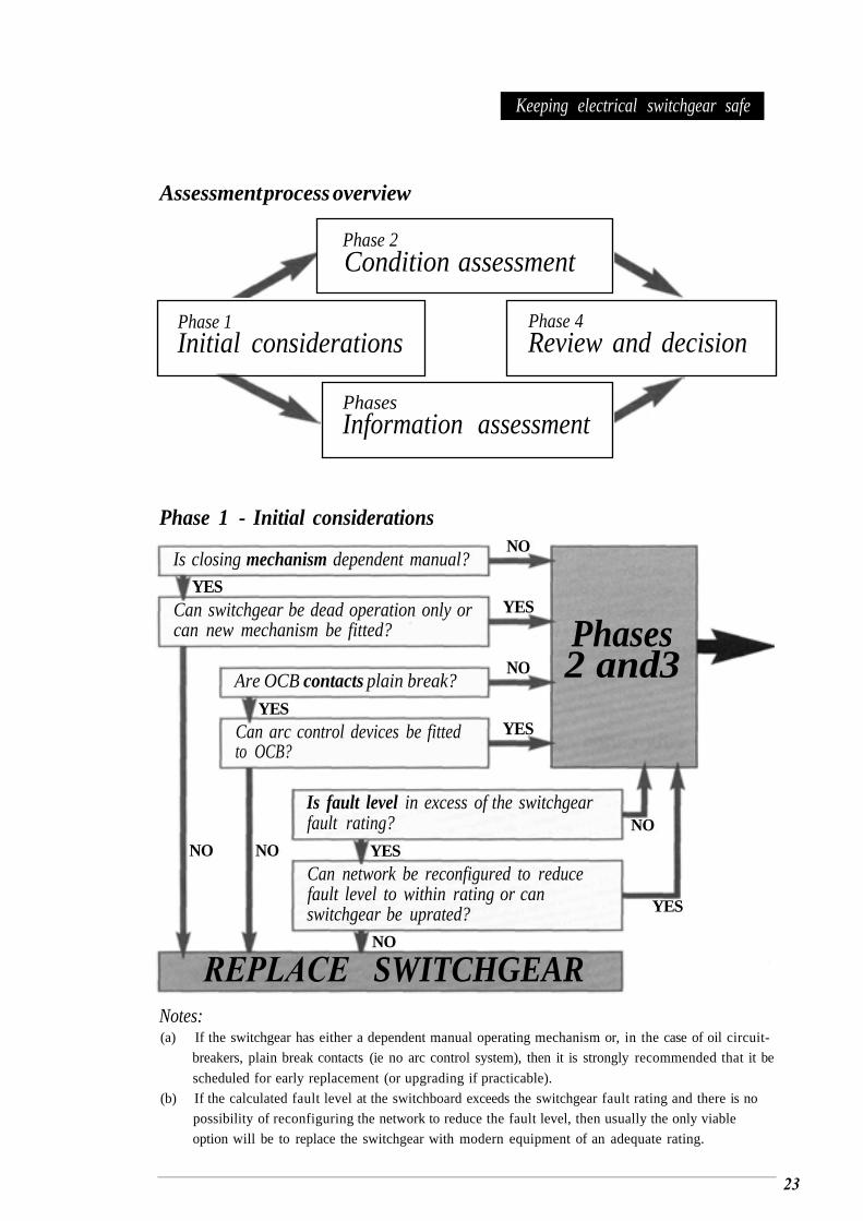
Keeping electrical switchgear safe
Assessment process overview
Phase 1 - Initial considerations
Is closing mechanism dependent manual?YES
Can switchgear be dead operation only orcan new mechanism be fitted?
Are OCB contacts plain break?
Can arc control devices be fittedto OCB?
Is fault level in excess of the switchgearfault rating?
Can network be reconfigured to reducefault level to within rating or canswitchgear be uprated?
NO
YES
NO
YES
Phases2 and3
NO
YES
NO
NONO YES
YES
Notes:(a) If the switchgear has either a dependent manual operating mechanism or, in the case of oil circuit-
breakers, plain break contacts (ie no arc control system), then it is strongly recommended that it be
scheduled for early replacement (or upgrading if practicable).
(b) If the calculated fault level at the switchboard exceeds the switchgear fault rating and there is no
possibility of reconfiguring the network to reduce the fault level, then usually the only viable
option will be to replace the switchgear with modern equipment of an adequate rating.
REPLACE SWITCHGEAR
Phase 2Condition assessment
Phase 1Initial considerations
Phase 4Review and decision
PhasesInformation assessment
23
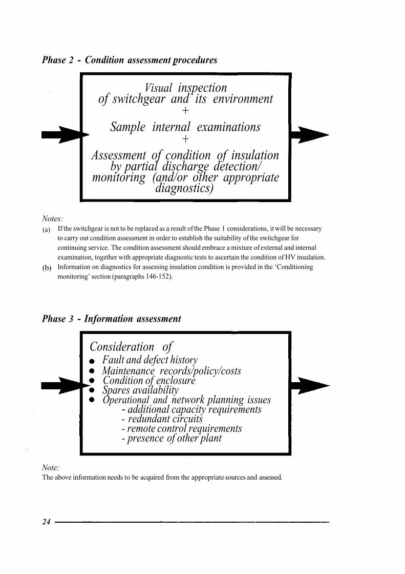
Phase 2 - Condition assessment procedures
Visual inspectionof switchgear and its environment
+Sample internal examinations
+Assessment of condition of insulation
by partial discharge detection/monitoring (and/or other appropriate
diagnostics)
Notes:(a) If the switchgear is not to be replaced as a result of the Phase 1 considerations, it will be necessary
to carry out condition assessment in order to establish the suitability of the switchgear for continuing service. The condition assessment should embrace a mixture of external and internal examination, together with appropriate diagnostic tests to ascertain the condition of HV insulation.Information on diagnostics for assessing insulation condition is provided in the ‘Conditioning monitoring’ section (paragraphs 146-152).
(b)
Phase 3 - Information assessment
Consideration ofFault and defect historyMaintenance records/policy/costs Condition of enclosure Spares availability Operational and network planning issues
- additional capacity requirements - redundant circuits - remote control requirements - presence of other plant
Note:The above information needs to be acquired from the appropriate sources and assessed.
24
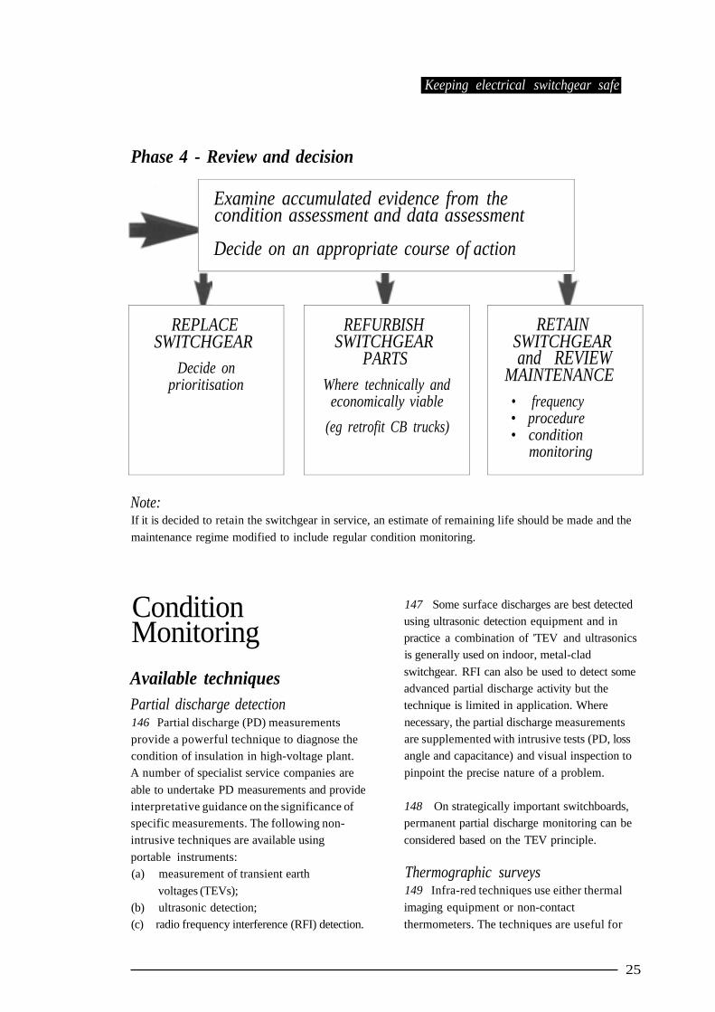
Keeping electrical switchgear safe
Phase 4 - Review and decision
Note:If it is decided to retain the switchgear in service, an estimate of remaining life should be made and the
maintenance regime modified to include regular condition monitoring.
ConditionMonitoringAvailable techniquesPartial discharge detection146 Partial discharge (PD) measurementsprovide a powerful technique to diagnose thecondition of insulation in high-voltage plant.A number of specialist service companies are
able to undertake PD measurements and provideinterpretative guidance on the significance ofspecific measurements. The following non-intrusive techniques are available using
portable instruments:(a) measurement of transient earth
voltages (TEVs);(b) ultrasonic detection;(c) radio frequency interference (RFI) detection.
147 Some surface discharges are best detectedusing ultrasonic detection equipment and inpractice a combination of 'TEV and ultrasonicsis generally used on indoor, metal-clad
switchgear. RFI can also be used to detect someadvanced partial discharge activity but thetechnique is limited in application. Where
necessary, the partial discharge measurementsare supplemented with intrusive tests (PD, lossangle and capacitance) and visual inspection to
pinpoint the precise nature of a problem.
148 On strategically important switchboards,permanent partial discharge monitoring can be
considered based on the TEV principle.
Thermographic surveys149 Infra-red techniques use either thermal
imaging equipment or non-contact
thermometers. The techniques are useful for
Examine accumulated evidence from thecondition assessment and data assessment
Decide on an appropriate course of action
REPLACESWITCHGEAR
Decide onprioritisation
REFURBISHSWITCHGEAR
PARTSWhere technically and
economically viable
(eg retrofit CB trucks)
RETAINSWITCHGEARand REVIEW
MAINTENANCE• frequency• procedure• condition
monitoring
25
detecting overheated conductors, connections and fuses on open-fronted, low-voltagedistribution boards or on other low-voltageswitchgear where live parts can be safely exposed and remotely scanned. These techniques are not particularly useful for indoor high-voltage, metal-clad switchboards but can detect overheating bushings and connections on open terminal switchgear.
Mechanism timing tests 150 Many problems in circuit-breakers are attributable to distortion or damage of the metal parts or ‘stiction’ in the mechanism causing failure to open or close, or slow opening of the circuit-breaker. Detection of a problem in a mechanism may not be fully dealt with by invasive maintenance and in fact may be more effectively dealt with by incorporating timingtests into the periodic trip-tests which can becarried out at the time of, or independently of, maintenance activities. Aswell asstraightforwardtiming, the use of trip-profile instruments provides a more detailed appreciation of the mechanism performance and is potentially a valuable additional test that can be incorporated into the routine trip-testing procedure. A number of instruments are available on the market and specialist organisations can provide a testing and assessment service.
Strategies for application 151 The application of diagnostic techniques, whether non-intrusive or intrusive, assists users by providing:
(a)
(b)
confidence in the continuing safety and reliability of the switchgear; a sound engineering basis for making investment decisions on plant replacement or refurbishment; the basis of a cost-reduced maintenance strategy, ie incorporating condition
.monitoring.
Switchgear that is not to be replaced as a
(c)
152
result of a condition assessment programme, and
is found suitable for further service, will require a maintenance regime modified to include some form of ongoing condition monitoring. Non-intrusive diagnostic techniques can form a part of that condition-monitoring programme.
ProtectionProtection relay schemes 153 The protection relays and associated systems should be subjected to regular inspection and diagnostic testing in addition to routine maintenance actions. Diagnostic testing will give an indication of the condition and comparison of test results with records of previous results will provide a guide to
possible deterioration and assist in determining the appropriate testing/maintenance interval. This procedure is valuable for estimation of trends.
154 Insulation resistance testing should be carried out on the secondary wiring associated with the protection, including any pilot wires if they form part of the protection circuitry. This is important since current leakage across the wiring will affect the characteristics of the protection scheme and may have a detrimental effect on the operation and discrimination of the protection scheme.
155 The checks and actions carried out for protection relay schemes should include:
(a) ensuring relay settings are correct; (b) inspection for condition, damage and
deterioration. For an electromechanical-type relay this should include checks that: - relay movement runs freely;- magnetgaps and induction discare clean; - contacts are not burnt or pitted
(refurbishasnecessary);- induction disc resetting time
(electromechanical IDMT relays); - flag mechanisms and reset knobs
operate correctly;
26
- front cover glass and seals are satisfactory; - current transformer shorting contacts
secondary injection tests to check operating characteristics. These tests will be dependent on the protection type (instantaneous and IDMT overcurrent/earth fault, directional,auto-reclose, unit, distance, motor protection etc) and whether time-limit fuses are used. Guidance on the test procedure can be obtained from manufacturers or specialist testing companies; checking the correct operation of load ammeters and any other instruments;
trip-testing of the circuit-breaker from the protection;inspection of the associated current and voltage transformers where appropriate.
operate satisfactorily;
(c)
(d)
(e) insulation resistance testing.
(f)
(g)
Fuse protection
156 For switchgear where the protection is dependent on fuse operation (eg switch fuses and fuse switches) then the operation tests involve carrying out fuse trip-testing (a test-tripfuse can be used if available) to ensure that:
(a) single fuse operation causes all other phases to operate;
(b) the manual ON/OFF trip mechanism operates correctly.
Batteries and chargers157 Batteries for circuit-breaker tripping and closing supplies play a vital role in the overall performance of the switchgear. The batteries and associated chargers need an appropriate maintenance regime in order to ensure consistent and reliable performance.
158 The battery/charger installation should be regularly inspected, tested and maintained. The level of maintenance attention will depend on
the type of battery and type of charger system in use. The battery manufacturer’s operation and maintenance instructions should be followed, and in particular, the recommended charging rates should be adhered to.
159
be carried out in accordance with the safety rules applicable to the work and only insulating tools complying with BS EN 60900 (see Appendix B ‘Further reading’) and other suitable equipment are to be used.
160
removal of connections does not inadvertently immobilise the switchgear or associated equipment.
162 Smoking or the use of naked flames should not be allowed in the proximity ofbattery installations and the production of sparks should be avoided due to inadvertent short-circuiting of cells.
162 When batteries are replaced it is important that the existing battery charger is compatible with the new batteries and old batteries are disposed of, observing the relevant environmental legislation.
All work on substation batteries needs to
Care needs to be taken to ensure that
Selection of new,replacement orrefurbishedswitchgearGeneral advice 163 A completely new switchboard installation will utilise the latest designs on offer from manufacturers. However, where a decision has to be taken to replace switchgear in an existing installation, then a number of options are available:
(a) replace the switchboard in its entirety;
27
(b)
(c)
(d)
replace the individual switchgear units (moving and fixed portion); refurbish the switchboards or individual switchgear units; retrofit the switchgear (this usually applies to circuit-breakers).
164 A major factor in such a decision is to obtain some technical confidence that the high-voltage insulation components of the busbar system, current transformer chambers, cables and terminations etc have adequate remaining life to justify any proposed expenditure on partial replacement, refurbishment or retrofitting. For this reason it is essential that an overall assessment of the switchgear is carried out before evaluating the economics of refurbishmendretrofit against replacement. This should include condition assessment of the high-voltage insulation using partial discharge measurement techniques. Included in this process is the evaluation of available test data and relevant standards. Wherecircuit-breakers are under consideration, it is also important to consider: (a) the condition of the secondary wiring,
protection and control equipment; (b) interlocking and earthing arrangements in
relation to current safety standards; (c) short-circuit ratings; (d) venting arrangement (where appropriate).
165 The availability of spares plays a role in the decision process. Consideration should be given to the availability of both strategic items (eg bushings, current transformer chambers, cable boxes, mechanisms) and routine maintenance items (eg arcing contacts, turbulator inserts, gaskets, tripping and closing coils). Confirmation should be sought as towhether spares are available from the original equipment manufacturer (OEM), or the OEMs successor companies, or from small ‘specialist’ engineering companies.
Ratings166 The load rating and the short-circuit rating of any new/refurbished/retrofit switchgear
should be assessed relative to that of any of thefixed portion and ancillary equipment such asthe current transformers that are to be retained. It is not unknown for users to overlook the fact that where there is a mismatch between the replaced/refurbished equipment and the existing equipment then the lowest load and short-circuit rating apply. Consequently, they may install uprated switchgear that cannot be utilised to its full rating.
Replacement installations 167 Where a complete new switchboard is to be installed, the opportunity exists to consider whether direct replacement is necessary or whether the switchboard arrangement can be simplified. You also need to take account of the possible additional capacity benefits and the reduced maintenance costs associated with the new switchgear. Also, less space will generally be required and the opportunity given to modernise the protection and control schemes.
168 Where only individual switchgear panels are to be replaced, then the decision is one of a like-for-like replacement, if it is still available, or of a modern equivalent (see also circuit-breakerretrofit option described in paragraphs 172-174).
169 It should be noted that old paper/lead cables can be internally damaged by significant disturbance and appropriate measures need to be taken to avoid this.
Refurbished/retrofittedswitchgear170 Users should only embark on the refurbishment and/or retrofit route after an overall assessment of those parts of the switchgear to be retained has been carried out. This is necessary toconfirm that the retained parts have adequate rating and sufficient remaining life to justify theexpenditure on refurbishment/retrofitting. Theoptions available are refurbishment of switchgear or retrofitting of circuit-breakers.
28
Refurbishment ofswitchgear171
the switchgear with replacement of parts deemed to be time-expired, eg operating mechanisms, insulation components etc.
This can be viewed as a major overhaul of
Retrofit circuit-breakers forwithdrawable switchgear 172
moving portions of switchgear, generally to incorporate vacuum or sulphur hexafluoride technology, for use with the existing fixed portions. Two options can be considered: (a) replacing the complete circuit-breaker
truck; or (b) modifying the existing truck to
incorporate a vacuum or sulphur hexafluoride circuit-breaker.
173 Retrofit systems can be obtained either from switchgear manufacturers or specialist retrofit suppliers. When selecting a system, particular attention should be paid to the mechanical compatibility between the fixed portion and the new moving portion. Problems can be experienced due to mechanical mismatch between the mating portions, shutter actuation, racking mechanisms and physical clearances. These are better addressed at the planning stage rather than attempting to cure them at the installation stage. Such problems can be minimised by close liaison between the user and supplier at all stages of a retrofit operation.
174 It is good practice to carry out a partial discharge survey of the switchboard, prior to installation of the retrofit units, to establish the integrity of the existing equipment and repeat the survey after installation to ensure that problems have not been exacerbated or introduced.
Retrofitting involves updating the existing
Second-hand equipment175 It is possible to purchase second-handswitchgear from companies specialising in the recovery of redundant switchgear and in its refurbishment for re-sale. If second-hand
switchgear is being considered, it is important to only deal with reputable and experienced organisations. Such organisations are required to provide documentation on the use and maintenance of the equipment. This would include information originating from the OEM.An audit of the contract by an independent consultant can be a worthwhile safeguard against purchase of equipment that might not be fit for purpose. The companies supplying the refurbished equipment though should ensure allrelevant items are dealt with during overhaul, upgrades, modifications etc.
Measuresto limit fires176 Failure of switchgear can lead to fires and where oil-filled equipment is involved the incident can be a major one. A serious incident not only poses potential fire and smoke risks to people in the vicinity and to the building fabric but may also affect other plant, thus escalating the primary event. There are a number of techniques that can be used singularly or in combination to mitigate the effects of a fire and limit smoke spread.
Compartmentation177 Substation plant items can be separated by fire-resisting barriers to limit the extent of any fire to the item of fire origin. If automatic extinction or control is required (see paragraphs 178-180), thencompartmentation is useful. However, there may be contradictory requirements between fire safety and explosion safety, for example where venting may be required to safeguard against explosion. Compartmentation needs to be carefully designed so that it can contain a fire but not inhibit any venting required for explosion control.
Control and extinction178 Fire-extinguishing systems use extinguishing mediums such as halon and carbon dioxide
29
(CO2 ). Halon is not a favoured medium due to environmental considerations but its use may be necessary in areas where fire hazards are particularly severe and could affect adjacent plant.
179 Such systems require the flooding of fire compartments and measures should be put in place to ensure that the system can be made non-automatic before entry to cater for occasions when personnel need to work in the area (see paragraphs 183-185). 184 Precautions should therefore be taken
180
fire-extinguishers and procedures for checking these and any permanent systems should also be carried out. Where problems are identified either inthe design, operation or during inspections, then corrective actions such as replacement, recharging and relocation etc should be taken.
area when the system operates. These include:
(a)
(b)(c)
asphyxiation by the gases or chemical extinguishants used; poisoning if extinguishants are toxic; physical injury (falling, striking objects etc) due to poor visibility after release of the gases or chemical extinguishants; effect of low temperature due to release of the gases or chemical extinguishants.
(d)
if people are to enter an area fitted with automatic fire protection equipment. These include:
(a)
(b)
A review of the use and provision of portable
the automatic control to be rendered inoperative before entry; caution notices indicating that the control is on ‘non-automatic’ to be fitted to the automatic/non-automatic selector; precautions taken to render the automatic control inoperative to be noted in any safety documents issued for work in the
instructions issued to staff to ensure that the system is restored to automatic control as soon as all staff have withdrawn from the area.
185 Notices requiring the above actions should be prominently displayed at the point(s) of access to the area.
(c)
Prevention181 The most appropriate control measure is protected area; that of prevention. The following strategies can be considered:
(a) good management of the plant items, eg careful control of workmanship, as there is a greater likelihood of an incident occurring after replacement or maintenance of equipment;careful monitoring of any degradation ofoil and dielectric insulation; reduction of possible ignition sources;
(d)
(b)
(c)
(d) good housekeeping. TrainingDetection General advice182
detection system could provide the electrical plant room or area with early fire detection and alarm features which could also be linked with a
control/extinction system to provide fast response fire suppression or control.
The use of an appropriate automatic tire 186 It is the duty of all users of switchgear to provide necessary training in order that staff involved in the operation and maintenance of switchgear are able to carry out their duties in safety and without risk to health. Many organisations offer a full range of training courses, from general appreciation of site access and responsibilities through to detailed courses on operations, safety, maintenance practice etc.
(a) electricity distribution companies;
Safety issues183 Where automatic fire protection systems are Such organisations include: installed there are risks to people in the protected
30
(b) training companies; (c) switchgear manufacturers; (d) technical services companies.
187 The use of a set of safety rules and a system of safety documents (see paragraph 188for definitions) that clearly and unambiguously state what actions are required to ensure safe working is essential, particularly at high voltage. To ensure that the different levels of activity associated with switchgear are performed competently and the safety rules are strictly adhered to, it is also important to define different categories of staff. This means you can clearly define the duties that are expected of them and, just as important, those they are not authorised to carry out. Typical categories are as follows (training courses can be prepared to meet the requirements of these categories):
(a) competent person - a person recognised ashaving sufficient technical knowledge and/or experience to enable them to avoid danger when carrying out their duties and who may be nominated to receive and clear specified safety documents; authorised person - a competent person who has been appointed in writing to carry out specified duties, including the issue and cancellation of safety documents, eg a permit-to-work or sanction for test.
(b)
Operational safety documents 188 The activities needed to operate, inspect, repair, maintain and test the switchgear will be designated to the appropriate category ofperson. In all cases, knowledge of the safety rules and application of the safety documents will be required, whether this be general understanding or detailed knowledge, plus an appreciation of the issues raised in this book. The implementation of a safety documents scheme is fundamental to safety in the use, care and maintenance of plant. The correct use of the following documents is essential. The naming of the documents varies between organisations - here are some suggested ones.
(a) Limitation of access - defines the limit within which work or testing (on LVswitchgear and systems) may be carried out and specifies necessary precautions. Permit-to-work - specifies the equipment to be worked on, the work to be carried out and the actions taken to achieve conditions which safeguard people working on the equipment from the dangers that are inherent in the system. Sanction for test - specifies the HV equipment to be tested, making known the conditions under which the testing is to be carried out and confirming actions taken to achieve conditions which safeguard persons testing the equipment from the dangers that are inherent in the system.
189 Operational safety documents are not intended (and should not be used) for work control purposes.
(b)
(c)
Inspection and maintenance190 Personnel engaged on the inspection and maintenance of switchgear will need to be made familiar with the procedures, safety rules and safety documents under which they work and their responsibilities to ensure safety and safe working. They will also need training in the technical aspects of their work.
Disposal issues191 Anyone who produces, treats, keeps, stores, transports or disposes of waste is subject to a duty of care under seasion 34 of the Environmental Protection Act 1990. This makes holders of waste responsible for its fate even after it has left their hands.
Insulating oil192
returned to oil companies and is subject to a process to generate reclaimed oil (which is sold
Much of the used oil from switchgear is
31
back to the users for reuse). Within the reclaiming and refining processes, the oil companies have their own quality assurance/quality control procedures, which should ensure that the quality and performance of the reclaimed oil beingsupplied back to users is satisfactory. It is standard practice within the oil companies to check the quality of batches of oil returned for reclaiming and reject those that are severely degraded. Userswith known batches of badly degraded oil shouldkeep it as separate waste oil for disposal by the oilcompanies in an appropriate manner.
293 Switchgear oil may contain polychlorinated biphenyls (PCBs), so theprocedures for handling used oil should take account of the approved handling procedures for PCB-contaminated materials or substances as laid down by:
(a) EU Directive 96/59/EC The Disposal of Polychlorinated Biphenyls and Polychlorinated Triphenyls; Statutory Instrument SI 2000 No 1034 TheDisposal of Polychlorinated Biphenyls and Other Dangerous Substances Regulations (England and Wales) May 2000.
194 As discussed in paragraphs 91-99, used switchgear oil may contain cadmium or cadmium sludge. Where this situation arises, the oil, cadmium sludge and all material containing it needs to be treated as ‘special waste’ and the disposal needs to be carried out as laid down by The Special Waste Regulations 1996. This includes all oil containing the cadmium and any new oil or solvents used to clean and rinse the components within the tank. Any wipes, gloves or clothing that have come into contact with the cadmium should be collected and sealed in boxes. All of this should then be appropriately labelled as special waste.
(b)
Capacitors
195 Some capacitors contain PCBs and therefore the procedures for disposal of capacitors should take account of approved handling procedures
for PCB-contaminated materials or substances -see the documents referred to in paragraph 193.
Sulphur hexafluoride switchgear196 As stated previously, there is a need to reduce emissions into the atmosphere and so procedures need to be in place to deal with the reclamation or disposal of sulphur hexafluoride gas removed from switchgear and for the disposal of switchgear containing sulphur hexafluoride. Advice on procedures can be obtained from the switchgear manufacturers and from specialist disposal companies. Guidance on the safe handling and final disposal is available from: (a) CIGRE Technical Brochure No 117, 1997
SF6 recycling guide. Re-use of SF6 gas inelectrical power equipment and final disposal;IEC Technical Report 1634, 1995 High-voltage switchgear and controlgear - useand handling of sulphur hexafluoride in high-voltage switchgear and controlgear.
197 Transportation by road of sulphurhexafluoride in gas bottles or equipment containing it is subject to national and local regulations. Information can be obtained from the European Agreement Concerning the International Carriage of Dangerous Goods by Road (ADR) and protocol of significance.
(b)
32

Appendices
Appendix A:
TechnicaldefinitionsLow voltageNormally exceeding 50 V ac or 120 V dc but not exceeding 1000 V ac or 1500 V dc between conductors, or 600 V ac or 900 V dc between conductors and earth.
High voltage Normally exceeding 1000 V ac or 1500 V dc between conductors, or 600 V ac or 900 V dc between conductors and earth.
‘Medium voltage’ Some companies and persons use the term ‘medium voltage’ to describe distribution voltages in range 3.3 kV to 72.5 kV todistinguish these from the higher values of voltage associated with transmission systems. There is no International Electrotechnical Vocabulary (IEV) meaning which specifies values; all that is stated is that the upper value lies between 30 kV and 100 kV. The term has not been used in the UK to prevent confusion with the widely understood use of the term for 415 V three-phase systems.
SwitchgearA combination of one or more switching devices together with associated control, measuring, signal, protective, regulating equipment etc completely assembled under the responsibility of the manufacturer with all the internal electrical and mechanical interconnections and structural parts.
Switching devices It is possible to separate switching devices into the following groups and to define the type of
switching device. It should be noted that they are all electromechanical devices.
IsolatorA switching device which is used to open (or close) a circuit either when negligible current is interrupted (or established) or when no significant change in the voltage across the terminals of each pole or phase of the isolator will result from the operation.
SwitchA switching device suitable for making or closing a circuit under normal and abnormal conditions, such as those of short-circuit, and capable of breaking or opening a circuit under normal conditions.
Circuit-breakerA switching device capable of making and breaking, or closing and opening, a circuit under normal conditions and under abnormal conditions such as those of short-circuit.
Switch fuseA switching device that is an integral assembly of switch and fuses in which a fuse is connected in series with the switch.
Fuse switchA switching device in which a fuse link or fuse carrier constitutes the moving contact.
Operating duties The operating duties of the above switching devices may be summarised as follows:
An isolator has no rated making or breaking capability, ie these devices can only be used for OFF-LOAD or DEADswitching.A switch is a FAULT MAKE/LOADBREAKdevice.A circuit-breaker is a FAULTMAKE/FAULT BREAK device.
Operating mechanism The types of operating mechanisms used for these switching devices are defined as follows:
34
Dependent manual operation (of amechanical switching device) (IEVDefinition 441-16-13)An operation solely by means of directlyapplied manual energy such that the speed and force of the operation are dependent upon the action of the operator. Independent manual operation (of a mechanical switching device) (IEVDefinition 44 1- 16-1 6) A stored energy operation where the energy originates from manual power, stored and released in one continuous operation, such that the speed and force of the operation are independent of the action of the operator. Dependent power operation (of a mechanical switching device) (IEVDefinition 44 1-1 6- 14)An operation by means of energy other than manual, where the completion of theoperation is dependent upon the continuity of the power supply (to solenoids, electric or pneumatic motors etc).
Independent power operation (of amechanical switching device) (IEVDefinition 441-16-6)A stored energy operation where the stored energy originates from an external power source and is released in one continuous operation, such that the speed and force of the operation are independent of the action of the operator. Stored energy operation (of a mechanical switchingdevice) (IEVDefinition 441-16-15)An operation by means of energy stored in the mechanism itself prior to thecompletion of the operation and sufficient to complete it under predetermined conditions. This kind of operation may be subdivided according to:(a) the manner of storing the energy
(spring, weight etc); (b) the origin of the energy (manual,
electric etc); (c) the manner of releasing the energy
(manual, electric etc).
35
Appendix B:
Further reading General advice (including HSEpublications)
The Health and Safety at Work etc Act 1974The Stationery Office 1974 ISBN 0 10 543774 3
Management of health and safety at work. Management of Health and Safety at Work Regulations 1999. Approved Code of Practice and guidance L21 (Second edition) HSE Books 2000 ISBN 0 7176 2488 9
Memorandum of guidance on the Electricity at Work Regulations 1989HSE Books 1989 ISBN 0 7176 1602 9
Occupational exposure limits: Containing the list of maximum exposure limits and occupational exposure standards for use with the Control of Substances Hazardous to Health Regulations 1999 Environmental Hygiene Guidance Note EH40 (revised annually) HSE Books 2002 ISBN 0 7176 2083 2
Working with cadmium: Are you at risk?Leaflet MSA7 HSE Books 1995 (also available on the HSE website at http://www.hse.gov.uk/pubns/msa7.htm)
Switchgear general CH Flurscheim Power circuit-breaker theory and design Peter Peregrinus Ltd 1985 ISBN 0906048702
R T Lythall The J and P Switchgear Book: An outline of modern switchgear practice for the non-specialist user 1972 editionNewnes/Butterworth-Heinemann ISBN 0408000694
BS 3078: 1959 Isolators (including selectors) for alternating current systems
BS 4752: 1977: Part 1 Switchgear and control gear for voltage up to and including 1000 Vacand 1200 V in dc circuit-breakers
BS 5311: 1976: Parts 1 to 5 AC circuit-breakersof rated voltage above 1 kV
BS 5311: 1996 High-voltage alternating-currentcircuit-breakers
BS 5463: 1977 AC switches of rated voltage above 1 kV
BS 60947: Specification for low-voltageswitchgear and controlgear -generalrequirements and circuit-breakers
BS 6423: 1983 Code of Practice for main-tenance of electrical switchgear and controlgear for voltages up to and including 1 kV
BS 6626: 1985 Code of Practice for maintenance of electrical switchgear and controlgear for voltages above 1 kV and up to and including 36 kV
British Standards relating to oil switchgearBS 116: 1937 Part 1 Oil circuit-breakers, oil switches and oil isolating-switches for alternating current circuits (three-phase oil circuit-breakerswith breaking capacity ratings between 25 and500 MVA)
BS 116: 1952 Oil circuit-breakers for ac systems
BS 936: 1940 Oil circuit-breakers for medium voltage ac systems (up to 660 V)
BS 936: 1960 Oil circuit-breakers for medium voltage ac systems (up to 660 V)
BS 2631: 1955 Oil switches for alternatingcurrent systems
BS 5730: 1979 Monitoring and maintenance guide for mineral insulating oil electrical equipment (under review based on IEC 60422)
Handling and use of sulphurhexafluorideBS 5207: 1975 Specification for sulphur hemfluoride for electrical equipment
BS 5209: 1975 Code ofPractice for the testing of sulphur hemfluoride taken from electricalequipment
36
SF6 recycling guide: Re-use of SF6 gas in electrical power equipment and final disposal CIGRE Technical Brochure No 117 1997
Guidance on the safety aspects of work onsulphur hexafluoride-filled distribution equipment up to 145 kV EA EngineeringRecommendation G69 1988
IEC 376: 1971 Specification and acceptance of new sulphur hexafluoride
IEC 480: 1974 Guide to checking of sulphur hexafluoride (SF6 ) taken from electrical equipment
IEC 694: 1995 High-voltage switchgear and controlgear. Use and handling ofsulphurhexafluoride(SF6 ) in high-voltage switchgear and controlgear
High-voltage switchgear and controlgear - useand handling ofsulphur hexafluoride in high-voltage switchgear and controlgear IECTechnical Report 1634 (First edition) 1995.Reference No CEI/IEC 1634:1995.
LV installationsBS 7671: 2001 Requirement for ElectricalInstallations (IEE Wring Regulations) Seventeenth edition
Disposal of hazardous materials
EU Directive 96/59/EC The Disposal of Polychlorinated Biphenyls and Polychlorinated Triphenyls European Commission
The Disposal ofPolychlorinated Biphenyls and Other Dangerous Substances Regulations (England and Wales) SI 2000/1034 TheStationery Office May 2000
The Special Waste Regulations 1996The Stationery Office
European Agreement Concerning the International Carriage of Dangerous Goods by Road (ADR) and protocol of significance The Stationery Office
RCM backgroundSmith A M Reliability-centred maintenance Wiley New York 1992
Moubray J Reliability-centred maintenance Buttenvorth-Heinemann Oxford 1991
Generator protection settings Recommendations for the connection ofembeddedgenerating plant to the public electricity suppliers’ distributionsystemsElectricity Association Engineering Recommendation G59/1 1991
Recommendations for the connection ofembedded generating plant to public electricity suppliers’ distribution systems above 20 kV orwith outputs over 5 MW Electricity Association Engineering Recommendation G75 1996
Insulating tools BS EN 60900 1994 Hand tools for live working up to 1000 Vac and 1500 V dc
Ordering HSE publicationsPlease see inside back cover for details of how to order HSE publications.
British StandardsBritish Standards are available from BSI Customer Services, 389 Chiswick HighRoad, London W4 4AL Tel: 020 8996 9001 Fax: 020 8996 7001Website: www.bsi-global.com
Publications from the Stationery officeThe Stationery Office (formerly HMSO) publications are available from The Publications Centre, PO Box 276,London SW8 5DTTel: 0870 600 5522 Fax: 0870 600 5533Website: www.tso.com (They are also available from bookshops.)
37
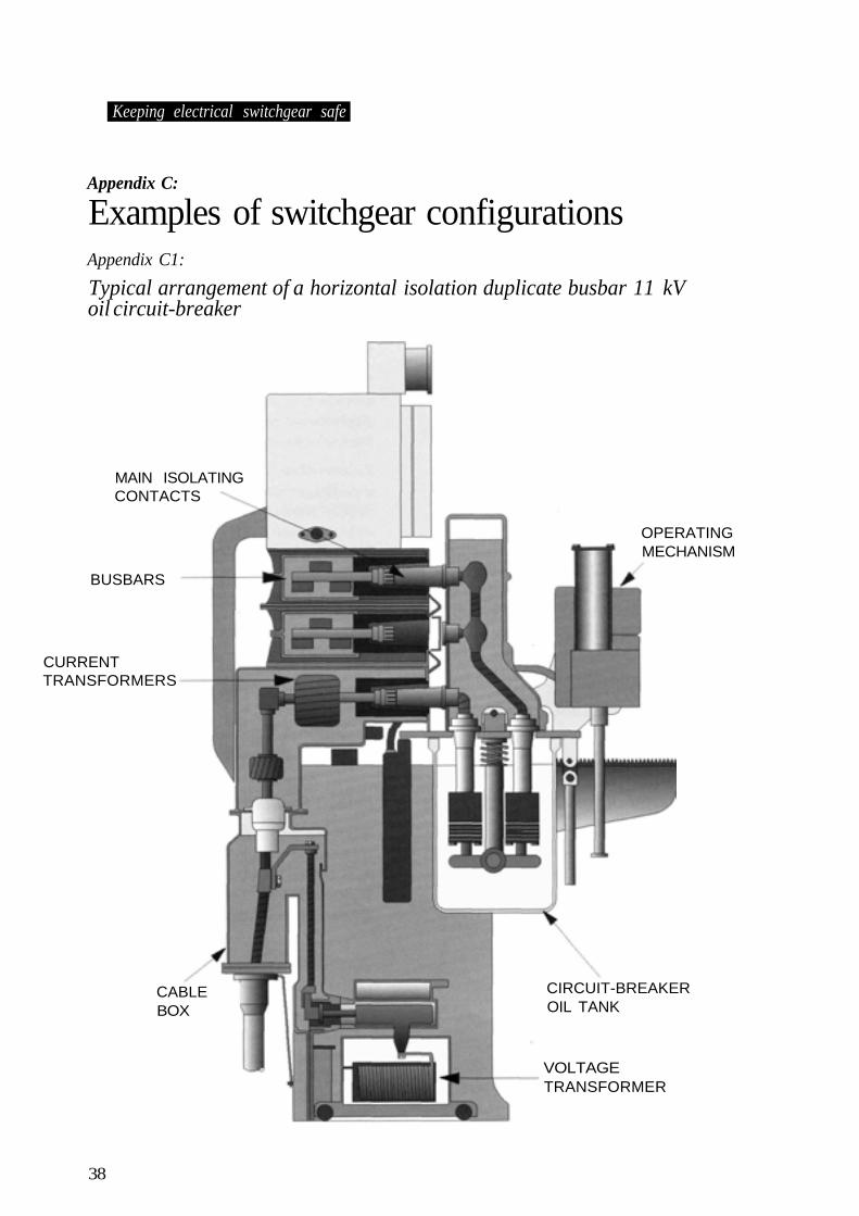
Keeping electrical switchgear safe
Appendix C:
Examples of switchgear configurationsAppendix C1:
Typical arrangement of a horizontal isolation duplicate busbar 11 kVoil circuit-breaker
MAIN ISOLATINGCONTACTS
BUSBARS
CURRENTTRANSFORMERS
CABLEBOX
OPERATINGMECHANISM
CIRCUIT-BREAKEROIL TANK
VOLTAGETRANSFORMER
38
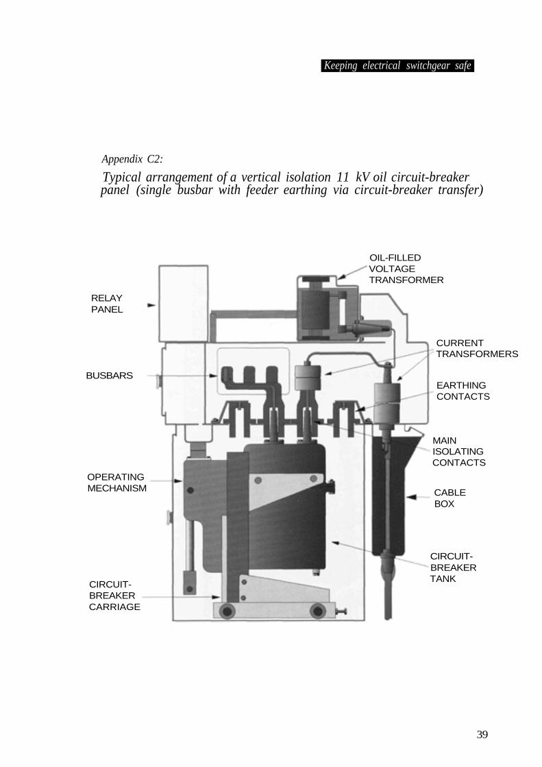
Keeping electrical switchgear safe
Appendix C2:
Typical arrangement of a vertical isolation 11 kV oil circuit-breakerpanel (single busbar with feeder earthing via circuit-breaker transfer)
OIL-FILLEDVOLTAGETRANSFORMER
RELAYPANEL
BUSBARS
OPERATINGMECHANISM
CIRCUIT-BREAKERCARRIAGE
CURRENTTRANSFORMERS
EARTHINGCONTACTS
MAINISOLATINGCONTACTS
CABLEBOX
CIRCUIT-BREAKERTANK
39
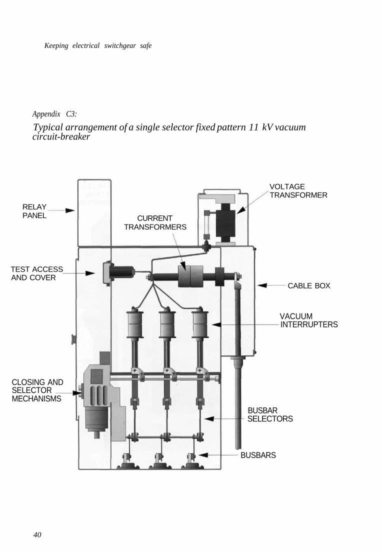
Keeping electrical switchgear safe
Appendix C3:
Typical arrangement of a single selector fixed pattern 11 kV vacuumcircuit-breaker
40
RELAYPANEL
TEST ACCESSAND COVER
CURRENTTRANSFORMERS
VOLTAGETRANSFORMER
CABLE BOX
VACUUMINTERRUPTERS
BUSBARSELECTORS
BUSBARS
CLOSING ANDSELECTORMECHANISMS
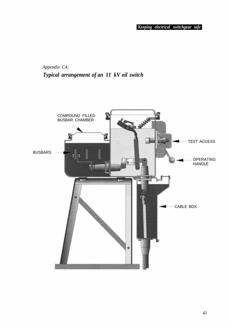
Keeping electrical switchgear safe
Appendix C4:
Typical arrangement of an 11 kV oil switch
COMPOUND FILLEDBUSBAR CHAMBER
BUSBARS
TEST ACCESS
OPERATINGHANDLE
CABLE BOX
41
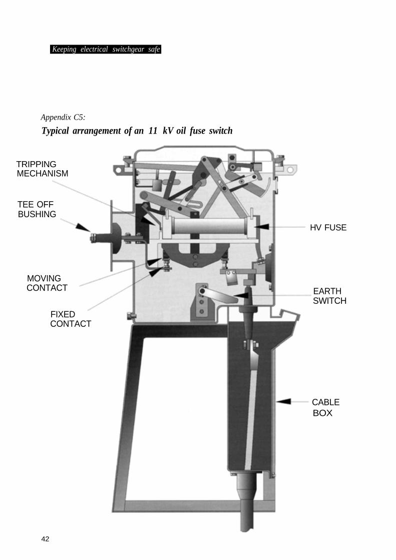
Keeping electrical switchgear safe
Appendix C5:
Typical arrangement of an 11 kV oil fuse switch
TRIPPINGMECHANISM
TEE OFFBUSHING
MOVINGCONTACT
FIXEDCONTACT
HV FUSE
EARTHSWITCH
CABLEBOX
42
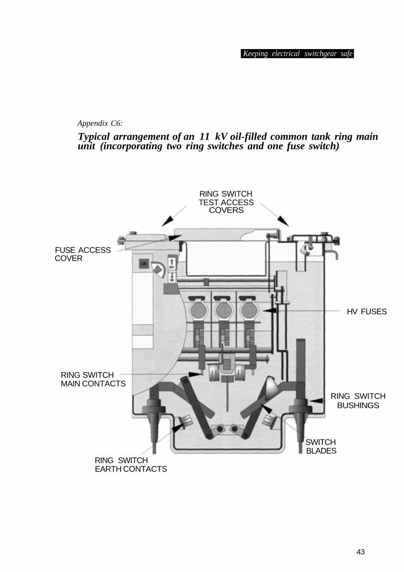
Keeping electrical switchgear safe
Appendix C6:
Typical arrangement of an 11 kV oil-filled common tank ring mainunit (incorporating two ring switches and one fuse switch)
FUSE ACCESSCOVER
RING SWITCHMAIN CONTACTS
RING SWITCHTEST ACCESS
COVERS
RING SWITCHEARTH CONTACTS
HV FUSES
RING SWITCHBUSHINGS
SWITCHBLADES
43
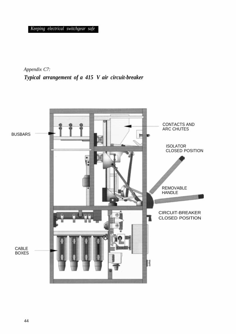
Appendix C7:
Typical arrangement of a 415 V air circuit-breaker
BUSBARS
CABLEBOXES
CONTACTS ANDARC CHUTES
ISOLATORCLOSED POSITION
REMOVABLEHANDLE
CIRCUIT-BREAKERCLOSED POSITION
44
Keeping electrical switchgear safe
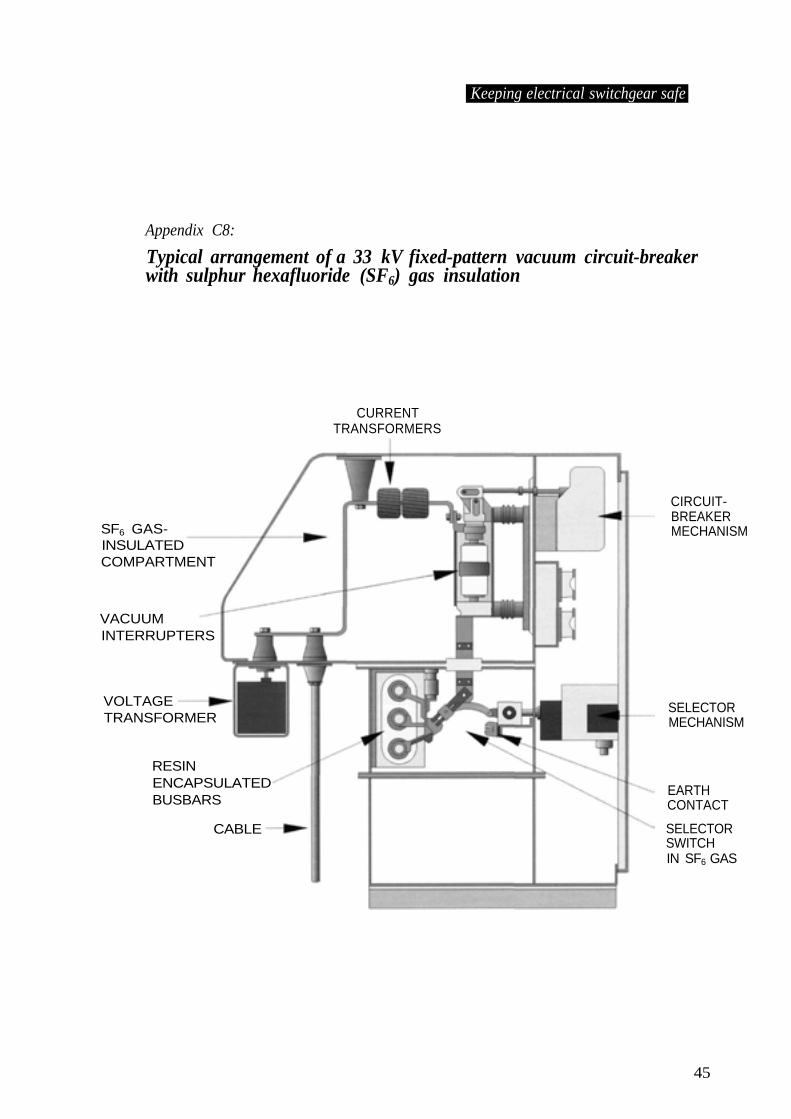
Keeping electrical switchgear safe
Appendix C8:
Typical arrangement of a 33 kV fixed-pattern vacuum circuit-breakerwith sulphur hexafluoride (SF6) gas insulation
CURRENTTRANSFORMERS
SF6 GAS-INSULATEDCOMPARTMENT
VACUUMINTERRUPTERS
VOLTAGETRANSFORMER
RESINENCAPSULATEDBUSBARS
CABLE
CIRCUIT-BREAKERMECHANISM
SELECTORMECHANISM
EARTHCONTACT
SELECTORSWITCHIN SF6 GAS
45
Appendix D:
Other sources ofinformationBritish Electrotechnical and AlliedManufacturers Association (BEAMA)Westminster Tower 3 Albert Embankment LondonSE1 7SL Tel: 020 7793 3000
TheInstitutionofElectrical Engineers (IEE)Savoy PlaceLondonWC2R 0BLTel: 020 7240 1871
Printed and published by the Health and Safety Executive C100 10/02