Electrical principles, magnet components and schematics, risks to and from magnets, protection
63
Electrical principles, magnet components and schematics, risks to and from magnets, protection MOPS Training Session 1 21.8.2008 KHM The nice ideas and pictures are stolen from M. Wilson , A. Siemko., R. Denz and P. Schmueser. The mistakes and the rest of it are mine. Apologies for the quality of pictures and talk. It had to be prepared in a hurry, parallel to HC.
description
Electrical principles, magnet components and schematics, risks to and from magnets, protection. MOPS Training Session 1 21.8.2008 KHM The nice ideas and pictures are stolen from M. Wilson , A. Siemko., R. Denz and P. Schmueser. The mistakes and the rest of it are mine. - PowerPoint PPT Presentation
Transcript of Electrical principles, magnet components and schematics, risks to and from magnets, protection
Electrical principles, magnet components and schematics, risks to
and from magnets, protection MOPS Training Session 1
21.8.2008KHM
The nice ideas and pictures are stolen from M. Wilson , A. Siemko., R. Denz and P. Schmueser. The mistakes and the rest of it are mine.
Apologies for the quality of pictures and talk. It had to be prepared in a hurry, parallel to HC.
Electrical principles, magnet components and schematics, risks to
and from magnets, protection
MOPS Training Session 121.8.2008
KHM
Outline
Components in a typical circuitEnergiesRisksEnergy Management (Protection)Quench DetectionReminder
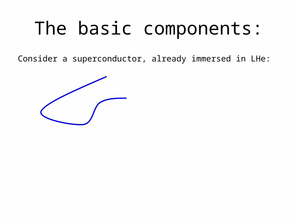
The basic components:Consider a superconductor, already immersed in LHe:
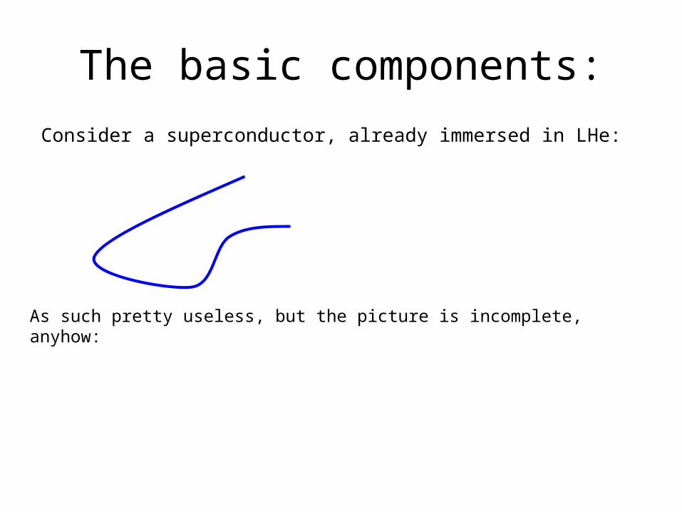
The basic components:Consider a superconductor, already immersed in LHe:
As such pretty useless, but the picture is incomplete, anyhow:
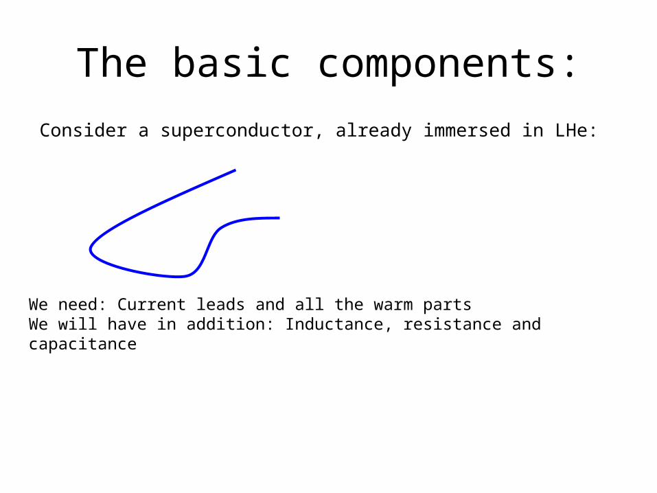
The basic components:Consider a superconductor, already immersed in LHe:
We need: Current leads and all the warm partsWe will have in addition: Inductance, resistance and capacitance
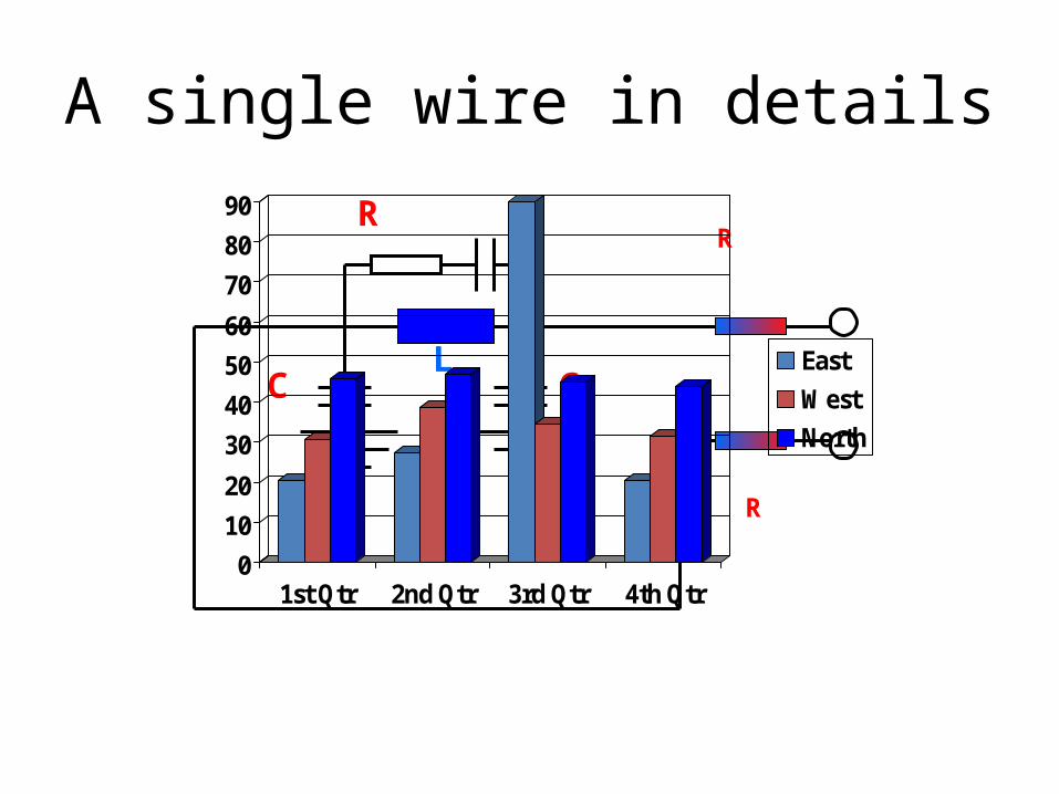
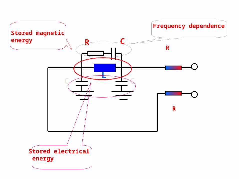
A single wire in details
LCC
CRR
R
01020
30405060
708090
1st Qtr 2nd Qtr 3rd Qtr 4th Qtr
EastWestNorth
LCC
CRR
R
Stored magneticenergy
Stored electrical energy
Frequency dependence
A single wire in detail

Stored Magnetic Energy
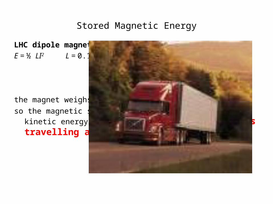
LHC dipole magnet (twin apertures) E = ½ LI2 L = 0.12H I = 11.5kA E = 7.8 x 10⁶ Joules
the magnet weighs 26 tonnes
so the magnetic stored energy is equivalent to the kinetic energy of: 26 tonnes travelling at 88km/hr
Stored Magnetic Energy
LHC dipole magnet (twin apertures) E = ½ LI2 L = 0.12H I = 11.5kA E = 7.8 x 10⁶ Joules
the magnet weighs 26 tonnes
so the magnetic stored energy is equivalent to the kinetic energy of: 26 tonnes travelling at 88km/hr
Stored Magnetic Energy
In a sector we have 154 magnets…in LHC we have 154*8 magnets
with a total stored energy of
E=9.6 GJ

Stored Magnetic Energy
In a sector we have 154 magnets…in LHC we have 154*8 magnets
with a total stored energy of
E=9.6 GJ
This corresponds a 100 000 to ship running at 27 knots.
Stored Magnetic Energy
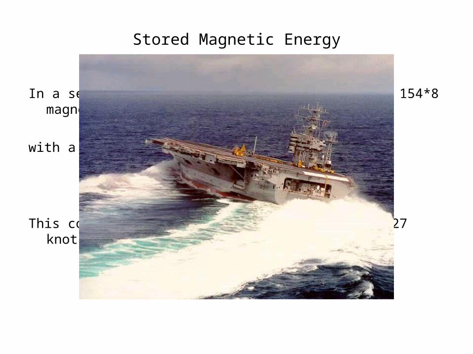
In a sector we have 154 magnets…in LHC we have 154*8 magnets
with a total stored energy of
E=9.6 GJ
This corresponds a 100 000 to ship running at 27 knots.
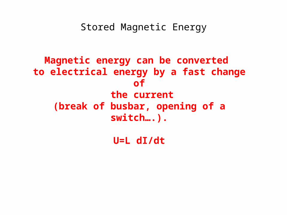
Stored Magnetic Energy
Magnetic energy can be converted to electrical energy by a fast change of
the current(break of busbar, opening of a switch….).
U=L dI/dt

3.6.03 K H Mess, LHC days 2003 15
3.6.03 K H Mess, LHC days 2003 16
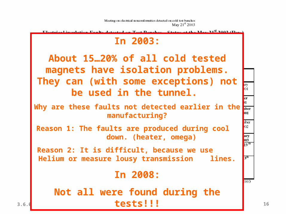
In 2003:
About 15…20% of all cold tested magnets have isolation problems.
They can (with some exceptions) not be used in the tunnel.
Why are these faults not detected earlier in the manufacturing?
Reason 1: The faults are produced during cool down. (heater, omega)
Reason 2: It is difficult, because we use Helium or measure lousy transmission lines.
In 2008:
Not all were found during the tests!!!
Back to the basics
Consider a superconductor, already immersed in LHe:
18
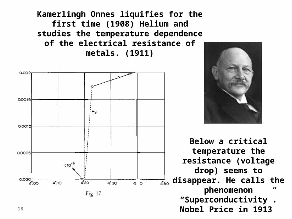
Kamerlingh Onnes liquifies for the first time (1908) Helium and studies the temperature dependence of the
electrical resistance of metals. (1911)
Below a critical temperature the
resistance (voltage drop) seems to disappear. He calls the phenomenon “Superconductivity”.Nobel Price in 1913
19
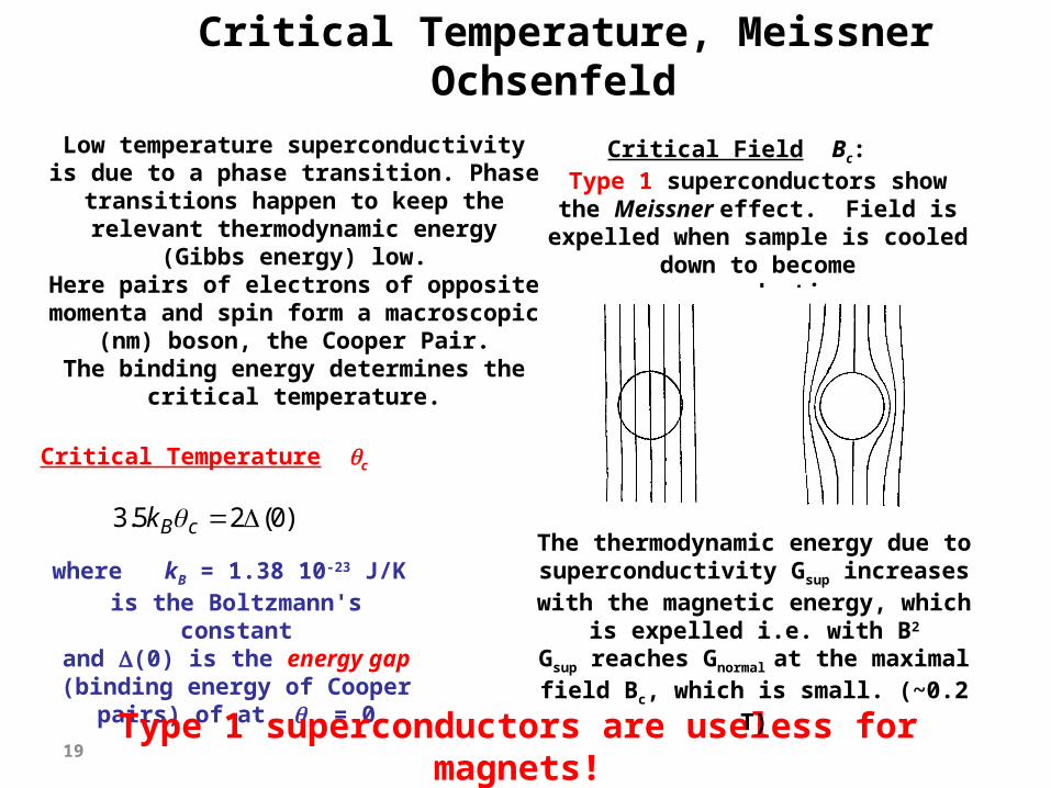
Critical Temperature, Meissner Ochsenfeld
Critical Temperature c
)0(25.3 cBk
Critical Field Bc: Type 1 superconductors show the Meissner effect. Field is
expelled when sample is cooled down to become
superconducting.
Low temperature superconductivity is due to a phase transition. Phase
transitions happen to keep the relevant thermodynamic energy
(Gibbs energy) low.Here pairs of electrons of opposite
momenta and spin form a macroscopic (nm) boson, the Cooper
Pair.The binding energy determines the
critical temperature.
where kB = 1.38 10-23 J/K is the Boltzmann's constant
and (0) is the energy gap (binding energy of Cooper pairs)
of at = 0
Type 1 superconductors are useless for magnets!
The thermodynamic energy due to superconductivity Gsup increases with the magnetic energy, which
is expelled i.e. with B2
Gsup reaches Gnormal at the maximal field Bc, which is small. (~0.2 T)
20
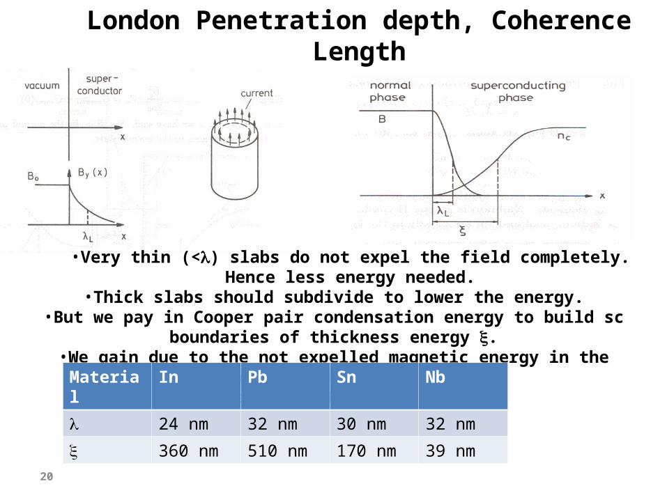
London Penetration depth, Coherence Length
•Very thin (<) slabs do not expel the field completely. Hence less energy needed.
•Thick slabs should subdivide to lower the energy.•But we pay in Cooper pair condensation energy to build sc
boundaries of thickness energy .•We gain due to the not expelled magnetic energy in the
penetration depth .•There is a net gain if > .
Material In Pb Sn Nb
24 nm 32 nm 30 nm 32 nm
360 nm 510 nm 170 nm 39 nm
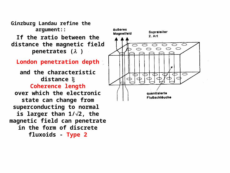
Ginzburg Landau refine the argument::
If the ratio between the distance the magnetic field penetrates ( )
London penetration depth
and the characteristic distance Coherence length
over which the electronic state can change from superconducting to
normal is larger than 1/2, the magnetic field can penetrate in the form of discrete fluxoids - Type 2
The coherence length is proportional to the mean free path of the conduction electrons.
2 is the area of a fluxoid. The flux in a fluxoid is quantised.
The upper critical field is reached, when all fluxoid touch. Bc2=0/(22).
Hence, good superconductors are always bad conductors (short free path).
Type 2 Superconductors are mostly alloys. Transport current creates a gradient in the fluxoid
pattern. Fluxoids must be movable to do that. However not too much, otherwise the field decays …..
Here starts the black magic.
23
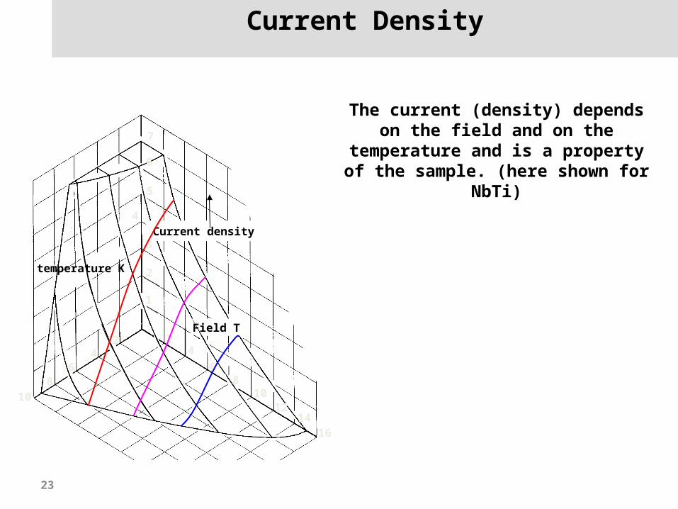
Current Density
108
64
2 24
68
1012
1416
Field T
1
2
3
4
5
6
7
Current density kAmm-2
temperature K
The current (density) depends on the field and on the
temperature and is a property of the sample. (here shown for
NbTi)
24
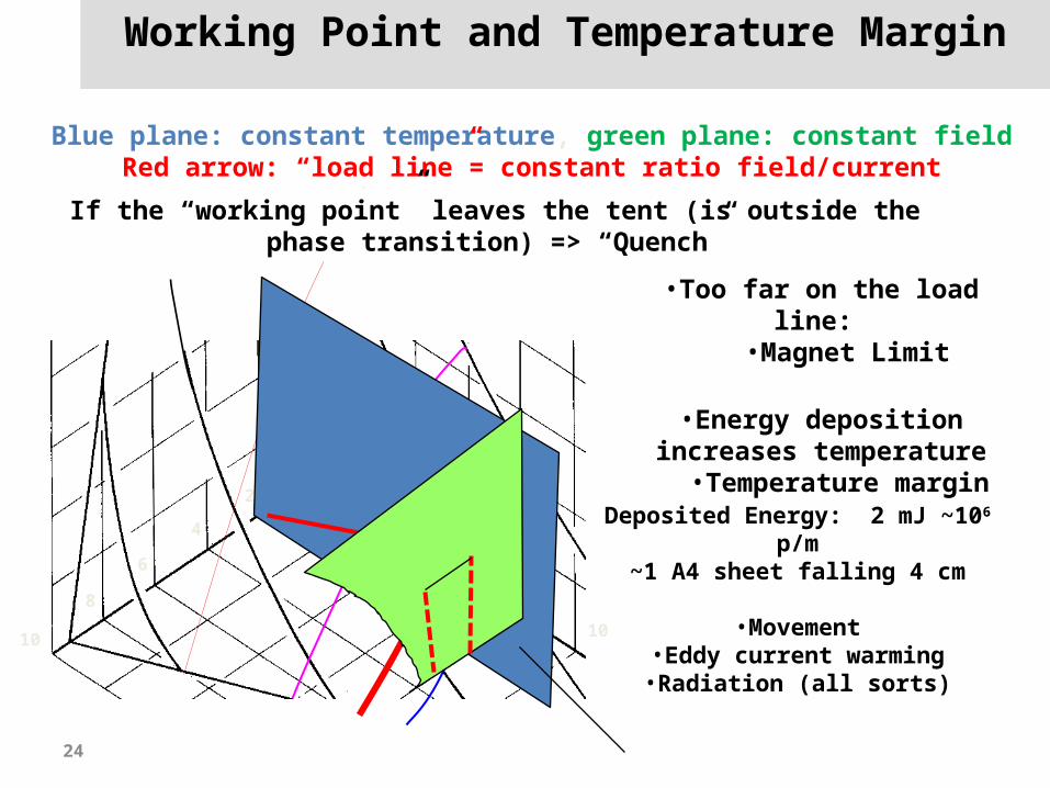
Working Point and Temperature Margin
10
8
6
4
2 2
4
6
8
10
Field T
1
2
Blue plane: constant temperature, green plane: constant fieldRed arrow: “load line”= constant ratio field/current
If the “working point” leaves the tent (is outside the phase transition) => “Quench”
•Too far on the load line: •Magnet Limit
•Energy deposition increases temperature
•Temperature margin
Deposited Energy: 2 mJ ~106 p/m
~1 A4 sheet falling 4 cm
•Movement•Eddy current warming
•Radiation (all sorts)
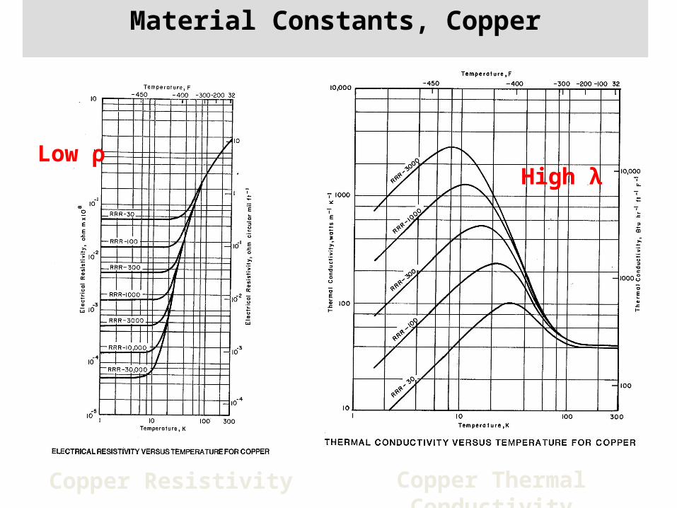
Material Constants, Copper
Copper Resistivity Copper Thermal Conductivity
Low ρ High λ
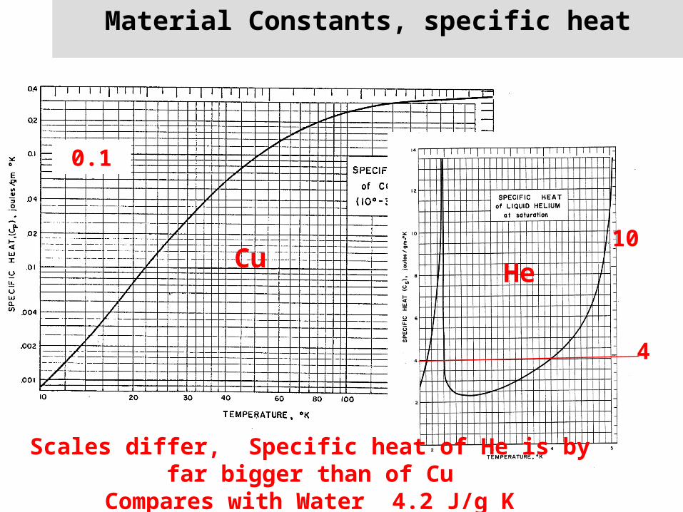
Material Constants, specific heat
Scales differ, Specific heat of He is by far bigger than of Cu
Compares with Water 4.2 J/g K
0.1
10Cu He
4
27
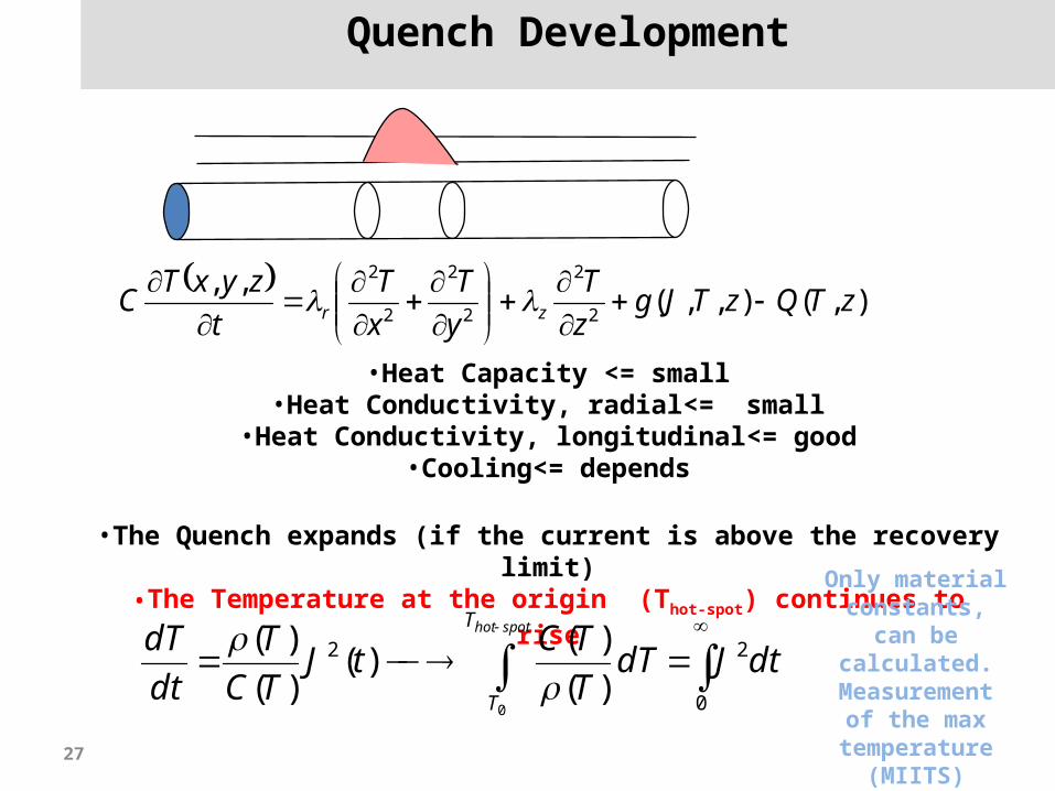
Quench Development
),(),,(
,,2
2
2
2
2
2
zTQzTJgz
T
y
T
x
T
t
zyxTC zr
•Heat Capacity <= small•Heat Conductivity, radial<= small
•Heat Conductivity, longitudinal<= good•Cooling<= depends
•The Quench expands (if the current is above the recovery limit)
•The Temperature at the origin (Thot-spot) continues to rise
spothotT
T
dtJdTT
TCtJ
TC
T
dt
dT
0 0
22
)(
)()(
)(
)(
Only material constants,
can be calculated.
Measurement of the max
temperature (MIITS)
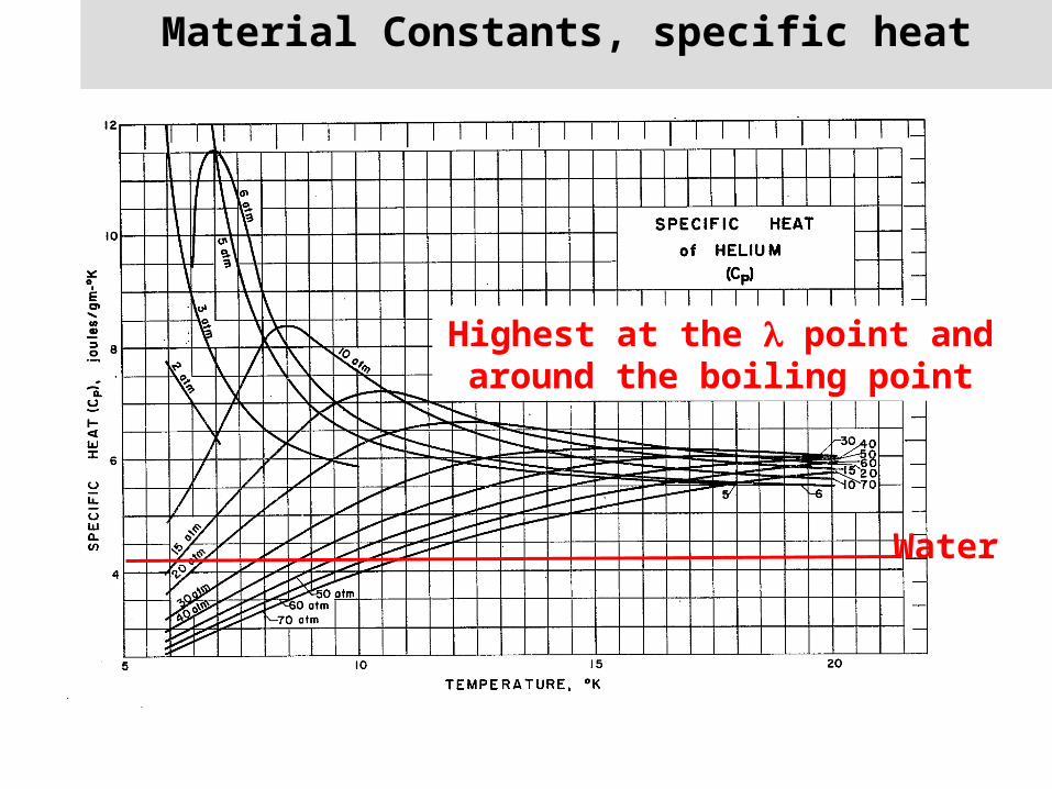
Material Constants, specific heat
Highest at the point and around the boiling point
Water

Slide 29Introduction to testing the LHC magnets - Info Sessions 2002
Magnet Quench – Quench Signal
Threshold
10ms validation window P
R O T E C T I O N
Introduction to testing the LHC magnets - Info
Sessions 2002, A. Siemko
30
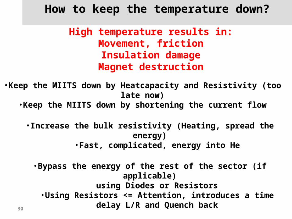
How to keep the temperature down?
•Keep the MIITS down by Heatcapacity and Resistivity (too late now)
•Keep the MIITS down by shortening the current flow
•Increase the bulk resistivity (Heating, spread the energy)
•Fast, complicated, energy into He
•Bypass the energy of the rest of the sector (if applicable)
using Diodes or Resistors•Using Resistors <= Attention, introduces a time
delay L/R and Quench back
•Extract the energy (External Resistors and Switches)•Slow, energy into air/water, needed to protect the
diodes
High temperature results in:Movement, frictionInsulation damageMagnet destruction
31
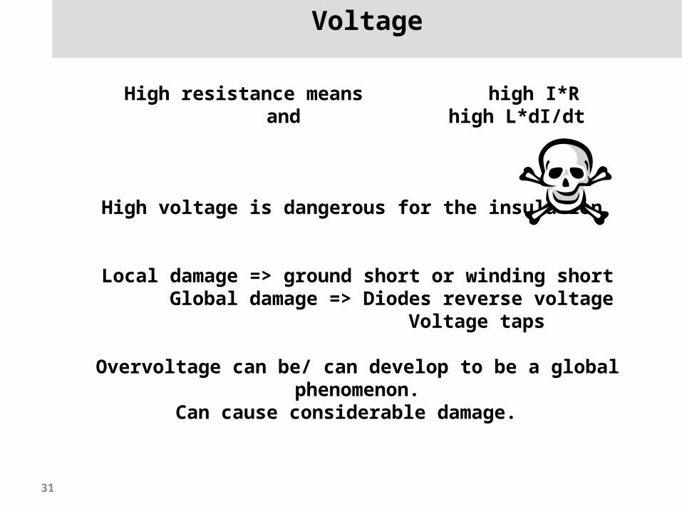
Voltage
High resistance means high I*R and high L*dI/dt
High voltage is dangerous for the insulation
Local damage => ground short or winding shortGlobal damage => Diodes reverse voltage
Voltage taps
Overvoltage can be/ can develop to be a global phenomenon.
Can cause considerable damage.
3.6.03 K H Mess, LHC days 2003 32
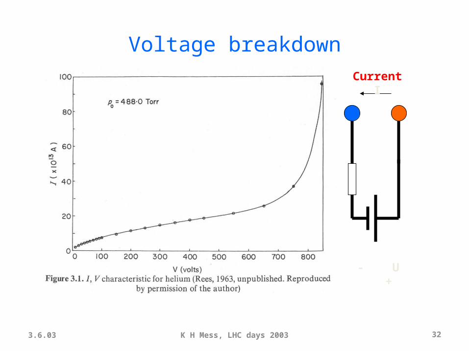
Voltage breakdown
- U +
Current I
3.6.03 K H Mess, LHC days 2003 33
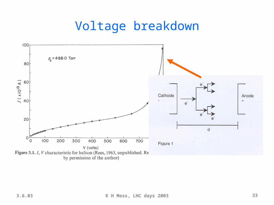
Voltage breakdown

3.6.03 K H Mess, LHC days 2003 34
U.V. light
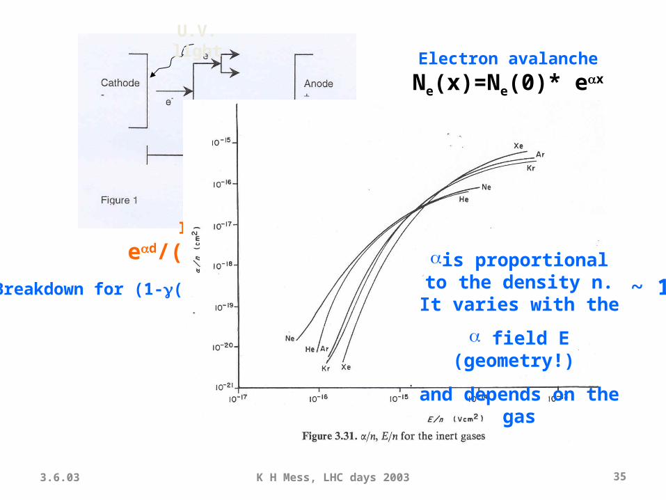
Electron avalanche
Ne(x)=Ne(0)* ex
Ion Bombardment
Per electron (ed-1) ions hit the Cathode
In total
ed/(1-(ed-1))
Breakdown for (1-(ed-1)) = 0 , ed>> 1 => e d ~ 1
3.6.03 K H Mess, LHC days 2003 35
U.V. light
Electron avalanche
Ne(x)=Ne(0)* ex
Ion Bombardment
Per electron (ed-1) ions hit the Cathode
In total
ed/(1-(ed-1))
Breakdown for (1-(ed-1)) = 0 , ed>> 1 => e d ~ 1
is proportional to the density n. It varies with the
field E (geometry!)
and depends on the gas
3.6.03 K H Mess, LHC days 2003 36
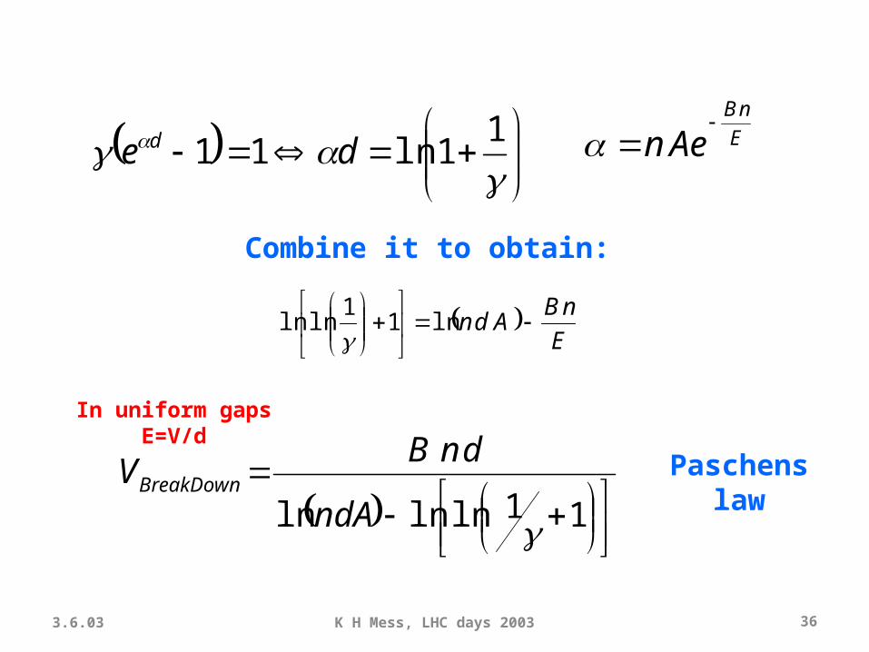
E
nB
Aen
1
1ln11 de d
E
nBAdn
ln1
1lnln
Combine it to obtain:
In uniform gaps E=V/d
11lnlnln ndA
dnBVBreakDown Paschens
law
3.6.03 K H Mess, LHC days 2003 37
E
nB
Aen
E
nBAdn
ln1
1lnln
Combine it
11lnlnln ndA
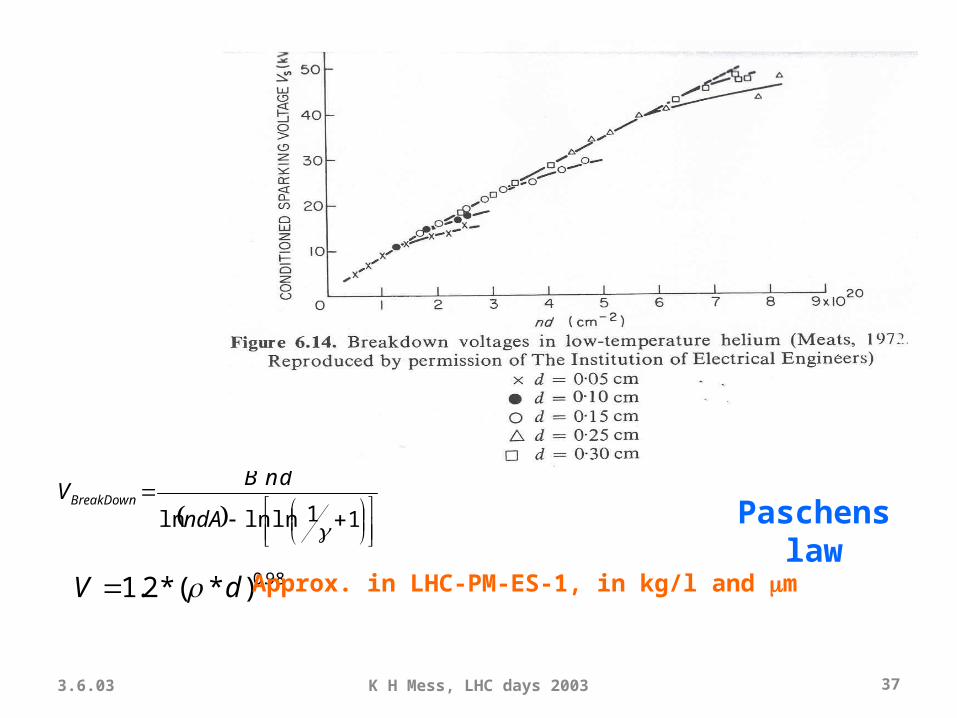
dnBVBreakDown
Paschens law
98.0)*(*2.1 dV Approx. in LHC-PM-ES-1, in kg/l and m

3.6.03 K H Mess, LHC days 2003 38
In air at this density
Vb=6.6kV !!!
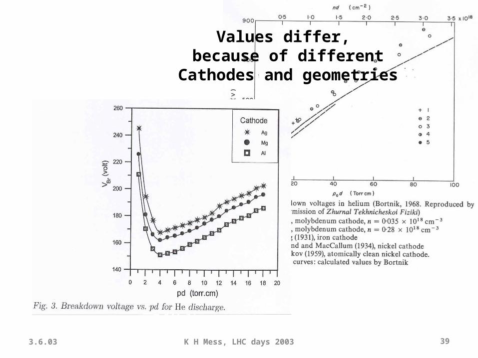
3.6.03 K H Mess, LHC days 2003 39
Values differ, because of different
Cathodes and geometries
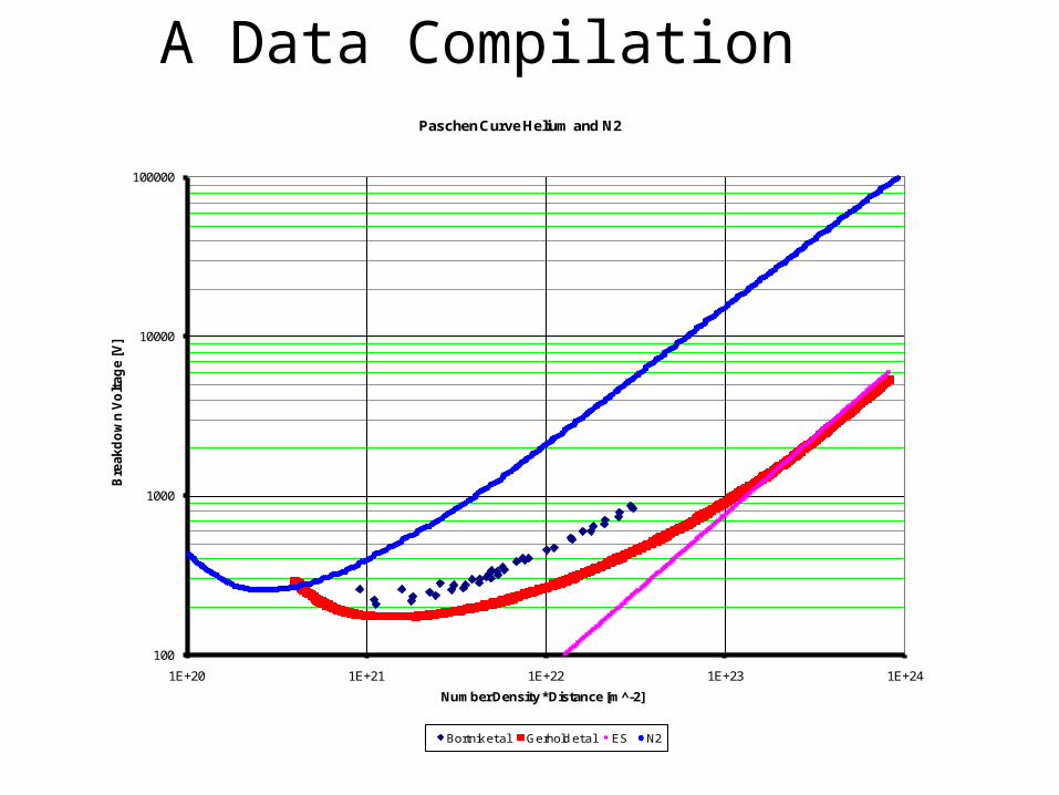
A Data Compilation
100
1000
10000
100000
1E+20 1E+21 1E+22 1E+23 1E+24
Bre
akd
ow
n V
olt
ag
e [V
]
Number Density * Distance [m -̂2]
Paschen Curve Helium and N2
Bortnik et al Gerhold et al ES N2

Minimal detectable distance for various scenarios in He
1 bar2
bar
6 bar
4.2 K gas
Liquid He
Breakdown Distance for various conditions
0.01
0.1
1
10
0 200 400 600 800 1000 1200 1400 1600 1800 2000
Voltage [V]
Dis
tan
ce [
mm
]
Distance @ 1 bar Distance @ 2 bar Distance @ 6bar Distance @ cold Distance in Lhe

3.6.03 K H Mess, LHC days 2003 42
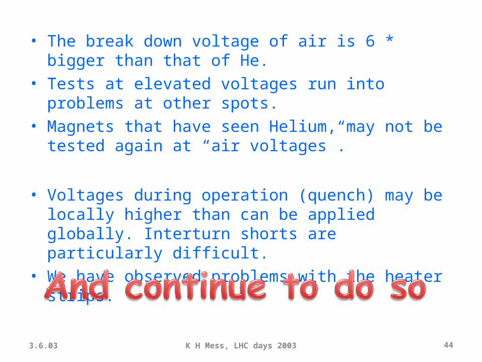
• The break down voltage of air is 6 * bigger than that of He.
• Tests at elevated voltages run into problems at other spots.
• Magnets that have seen Helium, may not be tested again at “air voltages”.
• Voltages during operation (quench) may be locally higher than can be applied globally. Interturn shorts are particularly difficult.
• We have observed problems with the heater strips.
3.6.03K H Mess, LHC days
200343
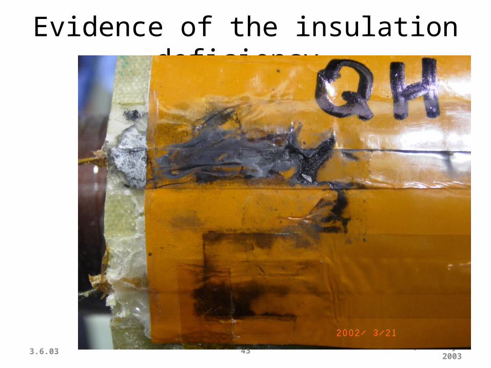
Evidence of the insulation deficiency
3.6.03 K H Mess, LHC days 2003 44
• The break down voltage of air is 6 * bigger than that of He.
• Tests at elevated voltages run into problems at other spots.
• Magnets that have seen Helium, may not be tested again at “air voltages”.
• Voltages during operation (quench) may be locally higher than can be applied globally. Interturn shorts are particularly difficult.
• We have observed problems with the heater strips.
Energy Management
• Divide et impera!• Treat sectors separately!• Detect resistive the transistion asap• Divide the energy in a magnet over many windings, using heaters (if necessary).• Guide the energy of all other 153 (or so) magnets around using a diode or resistor.• Protect the diode by a fast extraction of the energy.
Slide 46Introduction to testing the LHC magnets - Info Sessions 2002
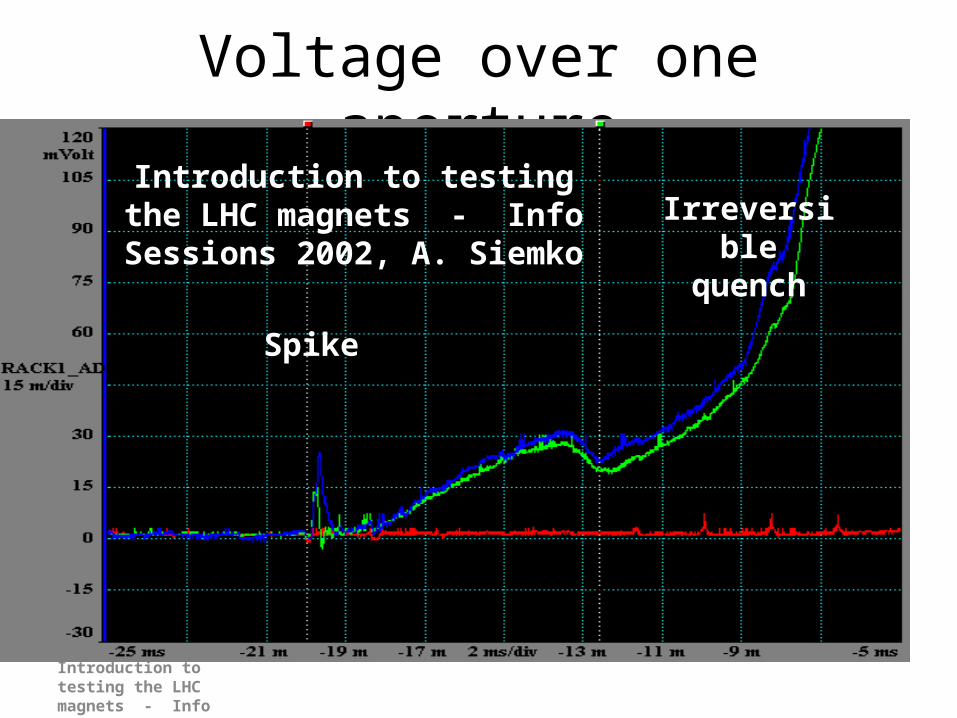
Voltage over one aperture
Spike
Irreversible quench
Introduction to testing the LHC magnets - Info
Sessions 2002, A. Siemko
Slide 47Introduction to testing the LHC magnets -
Info Sessions 2002
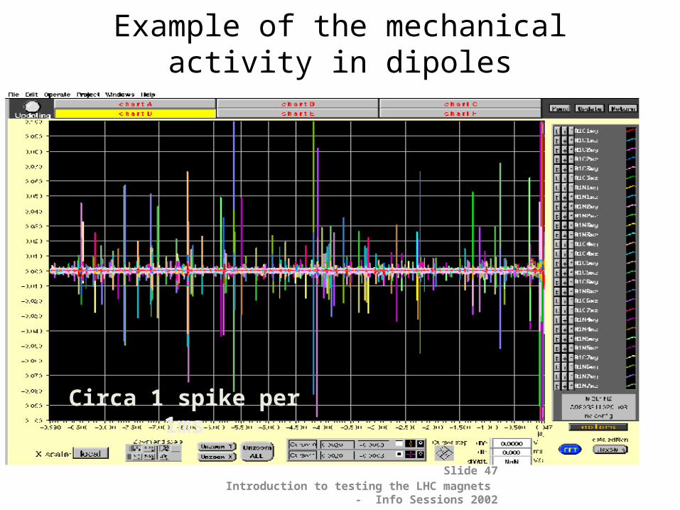
Example of the mechanical activity in dipoles
Circa 1 spike per 1ms

Quench - What Went Wrong?
• Abnormal voltage signals recorded during the provoked quench
Courtesy: A. Siemko
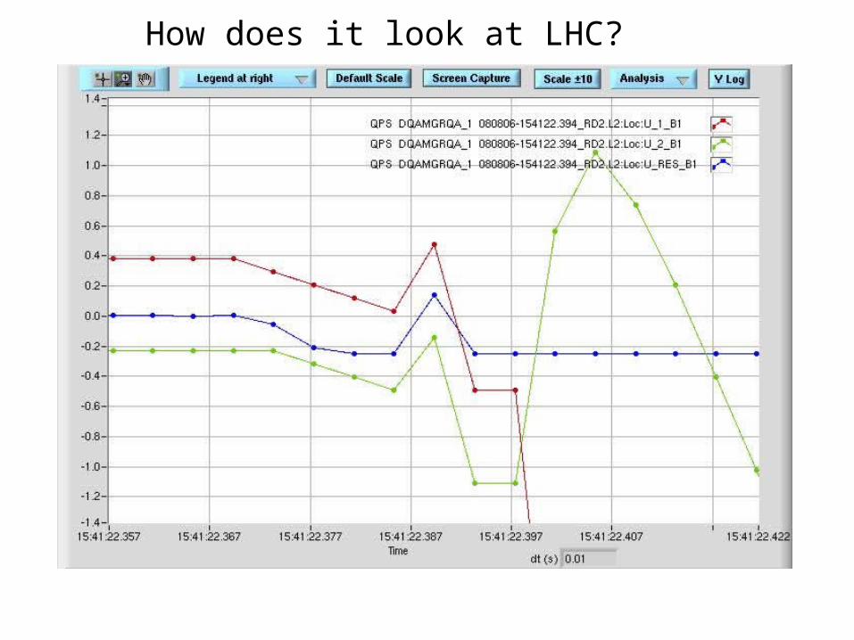
How does it look at LHC?
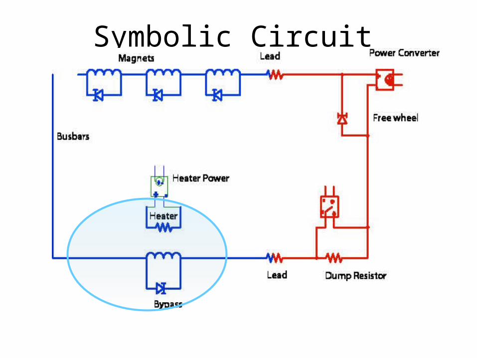
Symbolic Circuit
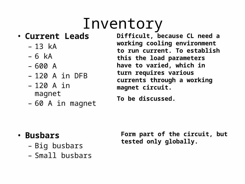
Inventory• Current Leads
– 13 kA– 6 kA– 600 A– 120 A in DFB– 120 A in
magnet– 60 A in magnet
• Busbars– Big busbars– Small busbars
Difficult, because CL need a working cooling environment to run current. To establish this the load parameters have to varied, which in turn requires various currents through a working magnet circuit.
To be discussed.
Form part of the circuit, but tested only globally.
Inventory• Magnets
– 13 kA circuits– 6 kA circuits– 600 A circuits– 120 A circuits– 60 A circuits
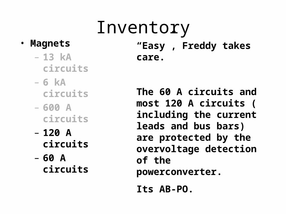
Inventory• Magnets
– 13 kA circuits
– 6 kA circuits– 600 A
circuits– 120 A
circuits– 60 A circuits
“Easy”, Freddy takes care.
The 60 A circuits and most 120 A circuits ( including the current leads and bus bars) are protected by the overvoltage detection of the powerconverter.
Its AB-PO.
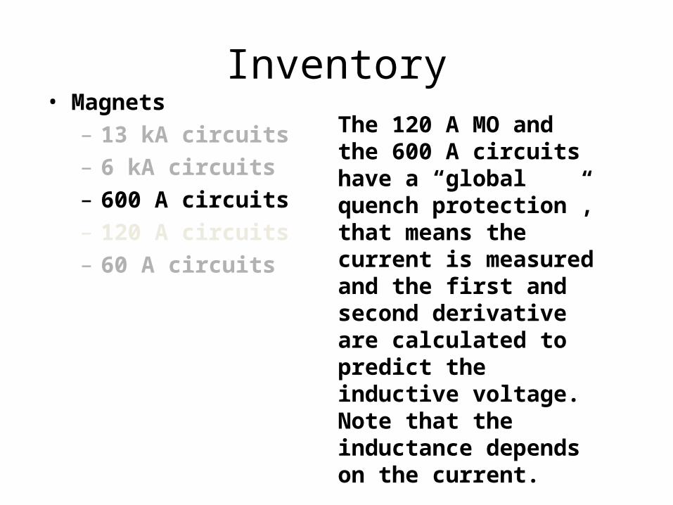
Inventory• Magnets
– 13 kA circuits– 6 kA circuits– 600 A circuits– 120 A circuits– 60 A circuits
The 120 A MO and the 600 A circuits have a “global quench protection”, that means the current is measured and the first and second derivative are calculated to predict the inductive voltage. Note that the inductance depends on the current.
Difficult

Global Quench Protection
DSP 24 bit ADC
Δ VΔ V
L dI/dt
InterlockFieldbus
Inventory• Magnets
– 13 kA circuits– 6 kA circuits– 600 A circuits– 120 A circuits– 60 A circuits
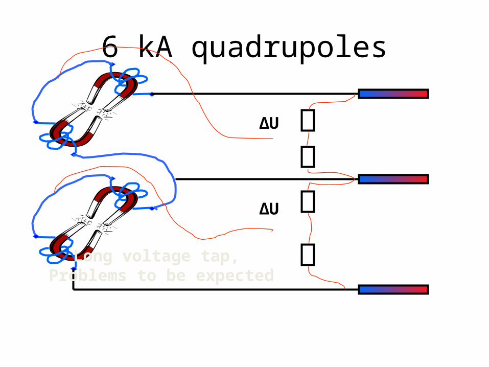
6 kA quadrupoles
ΔU
ΔU
Long voltage tap, Problems to be expected

Inventory• Magnets
– 13 kA circuits– 6 kA circuits– 600 A circuits– 120 A circuits– 60 A circuits

13 kA busbar protection
Courtesy R. Denz
Note that the reference magnets have to represent an average magnet!
Problem after a quench!
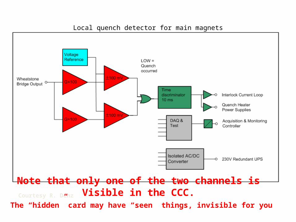
Local quench detector for main magnets
Courtesy R. Denz
Note that only one of the two channels isVisible in the CCC.
The “hidden” card may have “seen” things, invisible for you
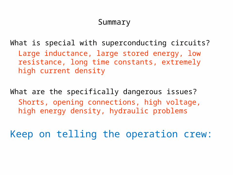
Summary
What is special with superconducting circuits?Large inductance, large stored energy, low resistance, long time constants, extremely high current density
What are the specifically dangerous issues?Shorts, opening connections, high voltage, high energy density, hydraulic problems
Keep on telling the operation crew:

62
We are pulling a tigers tail!.
H. Brechna, Superconducting Magnet Systems, Springer, Berlin 1973P. Schmueser, Superconducting magnets for particle accelerators,
Rep. Prog. Phys. 54 (191) 683M. N. Wilson, Superconducting Magnets, Clarendon Press, Oxford,
1983See also his lectures here and at CAS
A.Siemko, Introduction to testing the LHC magnets - Info Sessions 2002
http://nobelprize.org/nobel_prizes/physics/laureates/1913/onnes-lecture.pdf
http://www.bnl.gov/magnets/Staff/Gupta/cryogenic-data-handbook
KHM et al, Superconducting Accelerator Magnets, World Scientific, Singapore, 1996
References


![Permanent magnets Ferrite, ndFeB, alniCo & smCo … · NdFeB BLS Magnet [6] Permanent magnets BLS Magnet [7] Permanent magnets nDFeB magnets Grade Remanence Remanence Coercive force](https://static.fdocuments.net/doc/165x107/5b915de509d3f210288b8282/permanent-magnets-ferrite-ndfeb-alnico-smco-ndfeb-bls-magnet-6-permanent.jpg)

