Electrical Power Utilization Requirements for Electronic...
58
Electrical Power Utilization Requirements for Electronic Equipment on Military Aircraft 2012 Southern Tier Engineering Symposium & Professional Development Seminar Mike Elmore, Ph.D., P.E.
Transcript of Electrical Power Utilization Requirements for Electronic...

Electrical Power Utilization
Requirements for Electronic
Equipment on Military Aircraft
2012 Southern Tier Engineering Symposium &
Professional Development Seminar
Mike Elmore, Ph.D., P.E.

Mike ElmoreDirector of Engineering Design Division
Watson School of Engineering and Applied Science
Binghamton University
Experience
Lockheed Martin, Owego, NY (Systems Engineer)
EandM Power, Binghamton, NY (Consulting Engineer)
BAE Systems, Johnson City, NY (Systems Engineer)
IBM, Endicott, NY/Celestica Corp., Johnson City, NY (Hardware
Design Engineer & Manager)
General Electric, Johnson City, NY (Hardware Design Engineer)
Education
Ph.D., Electrical Engineering, Binghamton University
M.S.E.E., Electrical Engineering, Syracuse University
B.S.E.E., Electrical Engineering, University of Vermont
M. Ed., Secondary Math Education, University of Vermont
B.A., Philosophy, University of Vermont
Other
Professional Engineer (P.E.) NY State License and Registration
Senior Member of IEEE
Member of PELS, ASEE, SAE, & Tau Beta Pi
10/16/2012 2012 SOUTHERN TIER ENGINEERING SYMPOSIUM &
PROFESSIONAL DEVELOPMENT SEMINAR
2
Have done detailed power electronics
design for both military and commercial
products.
Was Electrical Power Working Group
lead and electrical power airworthiness
signatory on the VH-71 presidential
helicopter project.
Outline
Definitions
Military Aircraft Electrical Power Requirements
MIL-STD-704
Mid-term Quiz
Military Aircraft Electrical Power Test Procedures
MIL-HDBK-704
Other Aircraft Electrical Power Requirements in Brief
Final Exam
10/16/2012 2012 SOUTHERN TIER ENGINEERING SYMPOSIUM &
PROFESSIONAL DEVELOPMENT SEMINAR
3

Military Aircraft Electrical Power Requirements
MIL-STD-704 (6 October 1959)
MIL-STD-704A (9 August 1966)
MIL-STD-704B (17 November 1975)
MIL-STD-704C (30 December 1977)
MIL-STD-704D (30 September 1980)
MIL-STD-704E (1 May 1991)
MIL-STD-704F (12 March 2004)
10/16/2012 2012 SOUTHERN TIER ENGINEERING SYMPOSIUM &
PROFESSIONAL DEVELOPMENT SEMINAR
4

Definitions - Basic
3.29 Utilization equipment.
Utilization equipment is that equipment which receives power from the electric power system.
3.4 Aircraft electric power systems.
An aircraft electric power system consists of a main power source, emergency power sources, power conversion equipment, control and protection devices, and an interconnection network (wires, cables, connectors, etc.). The main power is derived from aircraft generators driven by the aircraft propulsion engines. Emergency power is derived from batteries, engine bleed air, independent auxiliary power units, ram air driven generators, or hydraulically driven generators.
10/16/2012 2012 SOUTHERN TIER ENGINEERING SYMPOSIUM &
PROFESSIONAL DEVELOPMENT SEMINAR
5
Definitions (1 of 6) Ref. 1

Aircraft Electrical Power Generation
System Example – Simplified Boeing 767
10/16/2012 2012 SOUTHERN TIER ENGINEERING SYMPOSIUM &
PROFESSIONAL DEVELOPMENT SEMINAR
6
Ref. 2
Main Gen Main Gen
Aux Gen
AC-to-DC AC-to-DC
Battery
AC Bus Tie Breakers
DC Bus Tie Breaker
Ref. 3
KC-46 tanker

Definitions – Normal Operation
3.18 Normal operation. (Electrical System)
Normal operation occurs when the system is operating as intended in the absence of any fault or malfunction that degrades performance beyond established requirements.
It includes all system functions required for aircraft operation except during the electric starting of propulsion engines and the battery start of an auxiliary power unit.
Normal operation includes switching of utilization equipment, prime mover speed changes, synchronizing and paralleling of power sources, and operation from external power sources.
4.2.2.1 Normal operation. (Utilization equipment)
Utilization equipment shall provide the level of performance specified in its detail specification.
10/16/2012 2012 SOUTHERN TIER ENGINEERING SYMPOSIUM &
PROFESSIONAL DEVELOPMENT SEMINAR
7
Ref. 1Definitions (2 of 6)
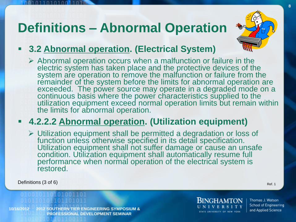
Definitions – Abnormal Operation
3.2 Abnormal operation. (Electrical System)
Abnormal operation occurs when a malfunction or failure in the electric system has taken place and the protective devices of the system are operation to remove the malfunction or failure from the remainder of the system before the limits for abnormal operation are exceeded. The power source may operate in a degraded mode on a continuous basis where the power characteristics supplied to the utilization equipment exceed normal operation limits but remain within the limits for abnormal operation.
4.2.2.2 Abnormal operation. (Utilization equipment)
Utilization equipment shall be permitted a degradation or loss of function unless otherwise specified in its detail specification. Utilization equipment shall not suffer damage or cause an unsafe condition. Utilization equipment shall automatically resume full performance when normal operation of the electrical system is restored.
10/16/2012 2012 SOUTHERN TIER ENGINEERING SYMPOSIUM &
PROFESSIONAL DEVELOPMENT SEMINAR
8
Ref. 1Definitions (3 of 6)

Definitions – Emergency Operation
3.13 Emergency operation. (Electrical System)
Emergency operation occurs following the loss of the main generating equipment when a limited electric source, independent of the main system, is used to power a reduced complement of distribution and utilization equipment selected to maintain flight and personnel safety.
3.2.2.4 Emergency operation. (Utilization equipment)
Utilization equipment shall provide the level of performance specified in its detail specification when such performance is essential for flight or safety.
10/16/2012 2012 SOUTHERN TIER ENGINEERING SYMPOSIUM &
PROFESSIONAL DEVELOPMENT SEMINAR
9
Ref. 1Definitions (4 of 6)

Definitions – Starting Operation
3.12 Starting operation. (Electrical System)
Electric starting operation is a specialized case of normal electric system operating conditions where the normal voltage limits may be exceeded due to the high electric demand. The voltage limits for normal operation may be exceeded during the following starting conditions:
a. An electric start of the propulsion engine. (Battery power, aircraft DC power or external power applied on the aircraft bus.)
b. A battery start of an auxiliary power unit.
4.2.2.5 Starting operation. (Utilization equipment)
Utilization equipment shall provide the level of performance specified in its detail specification when performance is essential during the starting operation.
10/16/2012 2012 SOUTHERN TIER ENGINEERING SYMPOSIUM &
PROFESSIONAL DEVELOPMENT SEMINAR
10
Ref. 1Definitions (5 of 6)

Definitions – Transfer Operation
3.27 Transfer operation. (Electrical System)
Transfer operation occurs when the electric system transfers between power sources, including transfers from or to external power sources.
4.2.2.3 Transfer operation. (Utilization equipment)
Utilization equipment may not be required to operate under the transfer condition unless a level of performance is specified by its detail specification. Utilization equipment shall automatically resume specified performance when normal operating characteristics are resumed.
10/16/2012 2012 SOUTHERN TIER ENGINEERING SYMPOSIUM &
PROFESSIONAL DEVELOPMENT SEMINAR
11
Ref. 1Definitions (6 of 6)

Summary of Modes
1. Normal
2. Abnormal
3. Emergency
4. Starting
5. Transfer
10/16/2012 2012 SOUTHERN TIER ENGINEERING SYMPOSIUM &
PROFESSIONAL DEVELOPMENT SEMINAR
12

FIGURE 1. Load
unbalance limits for
three-phase
utilization
equipment.
10/16/2012 2012 SOUTHERN TIER ENGINEERING SYMPOSIUM &
PROFESSIONAL DEVELOPMENT SEMINAR
13
Ref. 1

FIGURE 2. Phasor
diagram showing
required phase
sequence
relationship.
10/16/2012 2012 SOUTHERN TIER ENGINEERING SYMPOSIUM &
PROFESSIONAL DEVELOPMENT SEMINAR
14
Ref. 1

FIGURE 3. Envelope
of normal 400 Hz and
variable frequency
AC voltage transient.
10/16/2012 2012 SOUTHERN TIER ENGINEERING SYMPOSIUM &
PROFESSIONAL DEVELOPMENT SEMINAR
15
Ref. 1

FIGURE 4. Limits for 400 Hz and variable frequency AC
overvoltage or undervoltage.
10/16/2012 2012 SOUTHERN TIER ENGINEERING SYMPOSIUM &
PROFESSIONAL DEVELOPMENT SEMINAR
16
Ref. 1

FIGURE 5. Envelope
of normal 400 Hz AC
frequency transient.
10/16/2012 2012 SOUTHERN TIER ENGINEERING SYMPOSIUM &
PROFESSIONAL DEVELOPMENT SEMINAR
17
Ref. 1

FIGURE 6. Limits for
400 Hz AC
overfrequency or
underfrequency.
10/16/2012 2012 SOUTHERN TIER ENGINEERING SYMPOSIUM &
PROFESSIONAL DEVELOPMENT SEMINAR
18
Ref. 1
Does utilization equipment
have to work in this region?

FIGURE 7. Maximum distortion spectrum of 400 Hz and
variable frequency AC voltage.
10/16/2012 2012 SOUTHERN TIER ENGINEERING SYMPOSIUM &
PROFESSIONAL DEVELOPMENT SEMINAR
19
Ref. 1

FIGURE 8. Envelope
of normal 60 Hz
voltage transient.
10/16/2012 2012 SOUTHERN TIER ENGINEERING SYMPOSIUM &
PROFESSIONAL DEVELOPMENT SEMINAR
20
Ref. 1

FIGURE 9. Limits for 60 Hz AC overvoltage and undervoltage.
10/16/2012 2012 SOUTHERN TIER ENGINEERING SYMPOSIUM &
PROFESSIONAL DEVELOPMENT SEMINAR
21
Ref. 1

FIGURE 10.
Envelope of normal
60 Hz AC frequency
transient.
10/16/2012 2012 SOUTHERN TIER ENGINEERING SYMPOSIUM &
PROFESSIONAL DEVELOPMENT SEMINAR
22
Ref. 1

FIGURE 11. Limits
for 60 Hz AC
overfrequency and
underfrequency.
10/16/2012 2012 SOUTHERN TIER ENGINEERING SYMPOSIUM &
PROFESSIONAL DEVELOPMENT SEMINAR
23
Ref. 1

FIGURE 12. Maximum distortion spectrum of 60 Hz AC voltage.
10/16/2012 2012 SOUTHERN TIER ENGINEERING SYMPOSIUM &
PROFESSIONAL DEVELOPMENT SEMINAR
24
Ref. 1

FIGURE 13.
Envelope of normal
voltage transients
for 28 volts DC
system.
10/16/2012 2012 SOUTHERN TIER ENGINEERING SYMPOSIUM &
PROFESSIONAL DEVELOPMENT SEMINAR
25
Ref. 1

FIGURE 14. Limits for overvoltage and undervoltage
for 28 volts DC system.
10/16/2012 2012 SOUTHERN TIER ENGINEERING SYMPOSIUM &
PROFESSIONAL DEVELOPMENT SEMINAR
26
Ref. 1

FIGURE 15. Maximum distortion spectrum for 28 volts DC system.
10/16/2012 2012 SOUTHERN TIER ENGINEERING SYMPOSIUM &
PROFESSIONAL DEVELOPMENT SEMINAR
27
Ref. 1

FIGURE 16.
Envelope of normal
voltage transient for
270 volts DC system.
10/16/2012 2012 SOUTHERN TIER ENGINEERING SYMPOSIUM &
PROFESSIONAL DEVELOPMENT SEMINAR
28
Ref. 1

FIGURE 17. Limits for DC overvoltage and undervoltage
for 270 volts DC system.
10/16/2012 2012 SOUTHERN TIER ENGINEERING SYMPOSIUM &
PROFESSIONAL DEVELOPMENT SEMINAR
29
Ref. 1

FIGURE 18. Maximum distortion spectrum for 270 volts DC system.
10/16/2012 2012 SOUTHERN TIER ENGINEERING SYMPOSIUM &
PROFESSIONAL DEVELOPMENT SEMINAR
30
Ref. 1
Other
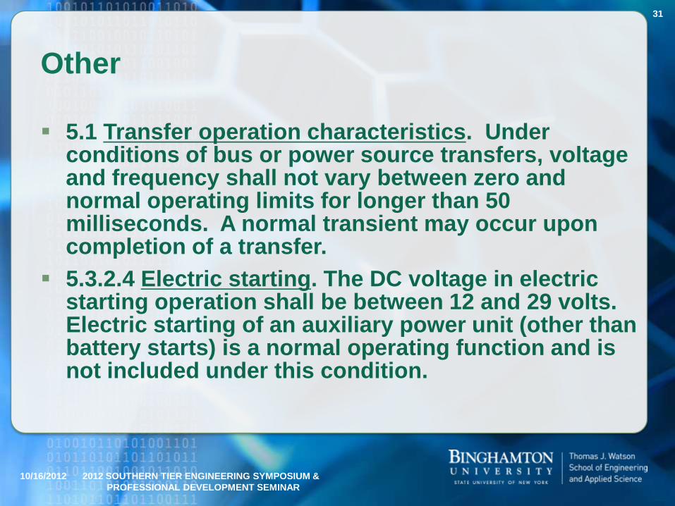
5.1 Transfer operation characteristics. Under conditions of bus or power source transfers, voltage and frequency shall not vary between zero and normal operating limits for longer than 50 milliseconds. A normal transient may occur upon completion of a transfer.
5.3.2.4 Electric starting. The DC voltage in electric starting operation shall be between 12 and 29 volts. Electric starting of an auxiliary power unit (other than battery starts) is a normal operating function and is not included under this condition.
10/16/2012 2012 SOUTHERN TIER ENGINEERING SYMPOSIUM &
PROFESSIONAL DEVELOPMENT SEMINAR
31

Midterm Quiz1. What is the current revision of MIL-STD-704?
ANS: F
2. What are the 5 operating modes of a military aircraft electrical system?
ANS: Normal, Abnormal, Emergency, Transfer, & Starting
3. (T / F) - Electrical utilization equipment is allowed to suffer damage during abnormal electrical system operation.
ANS: False
4. (T / F) - During emergency AC electrical system operation all power characteristics are the same as during normal AC operation.
ANS: True
5. (T / F) - During normal DC electrical system operation the DC voltage is always a steady-state 22.0 to 29.0 Volts.
ANS: False
10/16/2012 2012 SOUTHERN TIER ENGINEERING SYMPOSIUM &
PROFESSIONAL DEVELOPMENT SEMINAR
32

Military Aircraft Electrical Power Test Procedures
MIL-HDBK-704-1 – Overview
MIL-HDBK-704-2 – Single Phase, 400Hz, 115 Volt
MIL-HDBK-704-3 – Three Phase, 400Hz, 115 Volt
MIL-HDBK-704-4 – Single Phase, Variable Frequency, 115 Volt
MIL-HDBK-704-5 – Three Phase, Variable Frequency, 115 Volt
MIL-HDBK-704-6 – Single Phase, 60 Hz, 115 Volt
MIL-HDBK-704-7 – 270 VDC
MIL-HDBK-704-8 – 28 VDC
All published 9 April 2004
10/16/2012 2012 SOUTHERN TIER ENGINEERING SYMPOSIUM &
PROFESSIONAL DEVELOPMENT SEMINAR
33
28 VDC
Remember: MIL-STD-704 published 14 MAR 2004

MIL-HDBK-704-8 Test Methods
METHOD LDC101 Load Measurements
METHOD LDC102 Steady State Limits for Voltage
METHOD LDC103 Voltage Distortion Spectrum
METHOD LDC104 Total Ripple
METHOD LDC105 Normal Voltage Transients
METHOD LDC201 Power Interrupt
METHOD LDC301 Steady State Limits for Voltage
METHOD LDC302 Abnormal Voltage Transients
METHOD LDC401 Steady State Limits for Voltage
METHOD LDC501 Starting Voltage Transients
METHOD LDC601 Power Failure
METHOD LDC602 Phase Reversal
10/16/2012 2012 SOUTHERN TIER ENGINEERING SYMPOSIUM &
PROFESSIONAL DEVELOPMENT SEMINAR
34
Normal
Abnormal
Emergency

Typical Test Set-up for MIL-HDBK-704 Methods
10/16/2012 2012 SOUTHERN TIER ENGINEERING SYMPOSIUM &
PROFESSIONAL DEVELOPMENT SEMINAR
35
FIGURE LDC101-1.
Normal operation -
load and current
distortion
measurement.
Ref. 4
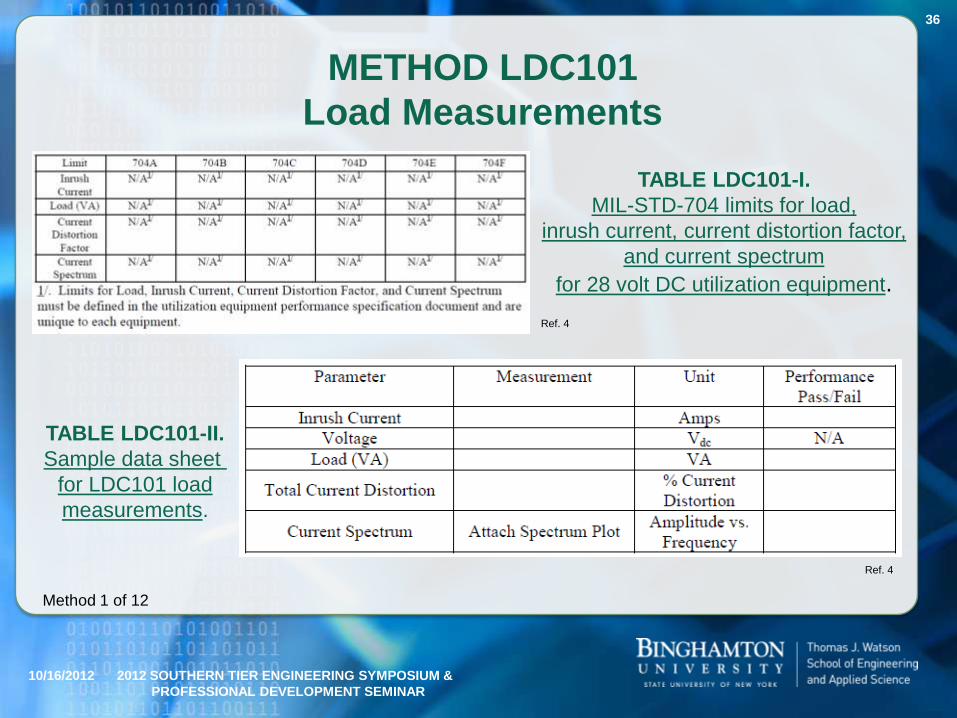
METHOD LDC101
Load Measurements
10/16/2012 2012 SOUTHERN TIER ENGINEERING SYMPOSIUM &
PROFESSIONAL DEVELOPMENT SEMINAR
36
Method 1 of 12
Ref. 4
TABLE LDC101-I.
MIL-STD-704 limits for load,
inrush current, current distortion factor,
and current spectrum
for 28 volt DC utilization equipment.
TABLE LDC101-II.
Sample data sheet
for LDC101 load
measurements.
Ref. 4

METHOD LDC102
Steady State (Normal) Limits for Voltage
10/16/2012 2012 SOUTHERN TIER ENGINEERING SYMPOSIUM &
PROFESSIONAL DEVELOPMENT SEMINAR
37
Method 2 of 12
TABLE LDC102-II.
Test conditions for steady state
limits of DC voltage.
TABLE LDC102-III.
Sample data sheet for LDC102 steady state limits for voltage.
Ref. 4
Ref. 4
Probably
an Error

METHOD LDC103
Voltage Distortion Spectrum.
10/16/2012 2012 SOUTHERN TIER ENGINEERING SYMPOSIUM &
PROFESSIONAL DEVELOPMENT SEMINAR
38
Ref. 1
Ref. 4
Method 3 of 12
TABLE LDC103-II.
Test conditions for voltage distortion spectrum.
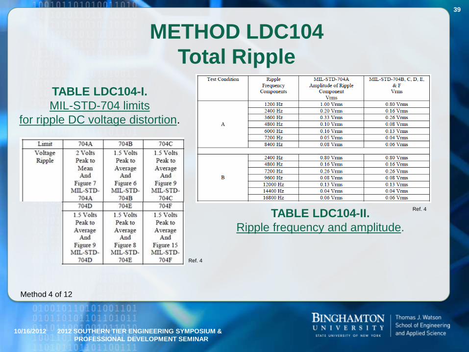
METHOD LDC104
Total Ripple
10/16/2012 2012 SOUTHERN TIER ENGINEERING SYMPOSIUM &
PROFESSIONAL DEVELOPMENT SEMINAR
39
Method 4 of 12
TABLE LDC104-I.
MIL-STD-704 limits
for ripple DC voltage distortion.
TABLE LDC104-II.
Ripple frequency and amplitude.
Ref. 4
Ref. 4

METHOD LDC105
Normal Voltage Transients
10/16/2012 2012 SOUTHERN TIER ENGINEERING SYMPOSIUM &
PROFESSIONAL DEVELOPMENT SEMINAR
40
Over
Under
Ref. 1Ref. 4
Method 5 of 12
TABLE LDC105-III.
Test conditions for MIL-STD-704B,
C, D, E and F
normal voltage transients.

METHOD LDC201
Power Interrupt
10/16/2012 2012 SOUTHERN TIER ENGINEERING SYMPOSIUM &
PROFESSIONAL DEVELOPMENT SEMINAR
41
Ref. 4
Method 6 of 12
TABLE LDC201-II.
Test conditions
for transfer interrupt.
Note: Transient

METHOD LDC301
Steady State (Abnormal) Limits for Voltage
10/16/2012 2012 SOUTHERN TIER ENGINEERING SYMPOSIUM &
PROFESSIONAL DEVELOPMENT SEMINAR
42
Method 7 of 12
TABLE LDC301-III. Sample data sheet for LDC301
abnormal steady state limits for voltage.
TABLE LDC301-II.
Test conditions for abnormal steady
state limits of DC voltage.
TABLE LDC301-I. MIL-STD-704 abnormal limits for steady state voltage.
Note: No
frequency
parameter here.
Ref. 4
Ref. 4
Ref. 4
Probably
Another Error

METHOD LDC302
Abnormal Voltage Transients
10/16/2012 2012 SOUTHERN TIER ENGINEERING SYMPOSIUM &
PROFESSIONAL DEVELOPMENT SEMINAR
43
Over
Ref. 1
Ref. 4
Method 8 of 12

METHOD LDC302
Abnormal Voltage Transients
10/16/2012 2012 SOUTHERN TIER ENGINEERING SYMPOSIUM &
PROFESSIONAL DEVELOPMENT SEMINAR
44
Under
Ref. 1
Ref. 4
Method 8 of 12

METHOD LDC302
Abnormal Voltage Transients
10/16/2012 2012 SOUTHERN TIER ENGINEERING SYMPOSIUM &
PROFESSIONAL DEVELOPMENT SEMINAR
45
Ref. 4
Method 8 of 12
Combined

METHOD LDC401
Steady State (Emergency) Limits for Voltage
10/16/2012 2012 SOUTHERN TIER ENGINEERING SYMPOSIUM &
PROFESSIONAL DEVELOPMENT SEMINAR
46
Method 9 of 12
TABLE LDC401-III. Sample data sheet for LDC401
emergency steady state limits for voltage and frequency.
TABLE LDC401-II.
Test conditions for emergency steady
state limits of DC voltage.
TABLE LDC401-I. MIL-STD-704 emergency limits for steady state voltage.
Note: No
Frequency
parameter
here,
but they put it
here.
Ref. 4
Ref. 4
Ref. 4

METHOD LDC501
Starting Voltage Transients
10/16/2012 2012 SOUTHERN TIER ENGINEERING SYMPOSIUM &
PROFESSIONAL DEVELOPMENT SEMINAR
47
TABLE LDC501-III. Test conditions for
MIL-STD-704D, E and F starting voltage transients.
Method 10 of 12
TABLE LDC501-IV. Sample data sheet for LDC501
starting voltage transients for MIL-STD-704A, B, C, D, E & F.
MIL-STD-704A,
B, and C are much
less severe.
Ref. 4
Ref. 4

METHOD LDC601
Power Failure
10/16/2012 2012 SOUTHERN TIER ENGINEERING SYMPOSIUM &
PROFESSIONAL DEVELOPMENT SEMINAR
48
Method 11 of 12
TABLE LDC601-II.
Test conditions for power failures.
TABLE LDC601-III.
Sample data sheet
for LDC601 power failure.
Power Failure Region
So, what is the difference with the undervoltage
region of METHOD LDC302? ANS: Duration
Ref. 4
Ref. 4
Ref. 1

METHOD LDC602
Phase Reversal
10/16/2012 2012 SOUTHERN TIER ENGINEERING SYMPOSIUM &
PROFESSIONAL DEVELOPMENT SEMINAR
49
Method 12 of 12
TABLE LDC602-I. MIL-STD-704 phase reversal requirement.
TABLE LDC602-II.
Sample data sheet
for LDC602 phase reversal.
Ref. 4
Ref. 4

Comparing MIL-STD-704 Editions
10/16/2012 2012 SOUTHERN TIER ENGINEERING SYMPOSIUM &
PROFESSIONAL DEVELOPMENT SEMINAR
50
28 VDC MIL-STD-704 Edition
A B D E F Comments on Editions B, D, E, and F
Normal Voltage Steady State
(NLSS)24 VDC 22 VDC 22 VDC 22 VDC 22 VDC No differences
Normal Voltage Steady State
(NHSS)28.5 VDC 29 VDC 29 VDC 29 VDC 29 VDC No differences
Voltage Distortion SpectrumFigure 7
MIL-STD-704A
Figure 6
MIL-STD-704B
Figure 9
MIL-STD-704D
Figure 8
MIL-STD-704E
Figure 15
MIL-STD-704F
No differences between E and F.
No differences between B and D to 20kHz.
E&F differ from B&D in the mid- to high
frequency range.
Voltage Ripple
2 Volts Peak
to Mean
Figure 7
MIL-STD-704A
1.5 Volts Peak
to Average
Figure 6
MIL-STD-704B
1.5 Volts Peak
to Average
Figure 9
MIL-STD-704D
1.5 Volts Peak
to Average
Figure 8
MIL-STD-704E
1.5 Volts Peak
to Average
Figure 15
MIL-STD-704F
No differences between E and F.
No differences between B and D to 20kHz.
E&F differ from B&D in the mid- to high
frequency range.
Normal Voltage Transients
Figure 9
MIL-STD-704A
Locus of
equivalent Step
Function Curves
2 and 3
Figure 7
MIL-STD-704B
Figure 10 MIL-
STD-704D
Figure 9 MIL-
STD-704E
Figure 13
MIL-STD-704FNo differences
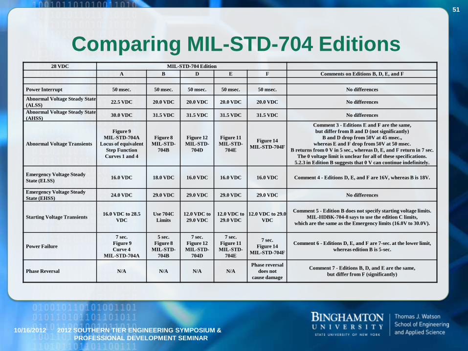
Comparing MIL-STD-704 Editions
10/16/2012 2012 SOUTHERN TIER ENGINEERING SYMPOSIUM &
PROFESSIONAL DEVELOPMENT SEMINAR
51
28 VDC MIL-STD-704 Edition
A B D E F Comments on Editions B, D, E, and F
Power Interrupt 50 msec. 50 msec. 50 msec. 50 msec. 50 msec. No differences
Abnormal Voltage Steady State
(ALSS)22.5 VDC 20.0 VDC 20.0 VDC 20.0 VDC 20.0 VDC No differences
Abnormal Voltage Steady State
(AHSS)30.0 VDC 31.5 VDC 31.5 VDC 31.5 VDC 31.5 VDC No differences
Abnormal Voltage Transients
Figure 9
MIL-STD-704A
Locus of equivalent
Step Function
Curves 1 and 4
Figure 8
MIL-STD-
704B
Figure 12
MIL-STD-
704D
Figure 11
MIL-STD-
704E
Figure 14
MIL-STD-704F
Comment 3 - Editions E and F are the same,
but differ from B and D (not significantly)
B and D drop from 50V at 45 msec.,
whereas E and F drop from 50V at 50 msec.
B returns from 0 V in 5 sec., whereas D, E, and F return in 7 sec.
The 0 voltage limit is unclear for all of these specifications.
5.2.3 in Edition B suggests that 0 V can continue indefinitely.
Emergency Voltage Steady
State (ELSS)16.0 VDC 18.0 VDC 16.0 VDC 16.0 VDC 16.0 VDC Comment 4 - Editions D, E, and F are 16V, whereas B is 18V.
Emergency Voltage Steady
State (EHSS)24.0 VDC 29.0 VDC 29.0 VDC 29.0 VDC 29.0 VDC No differences
Starting Voltage Transients16.0 VDC to 28.5
VDC
Use 704C
Limits
12.0 VDC to
29.0 VDC
12.0 VDC to
29.0 VDC
12.0 VDC to 29.0
VDC
Comment 5 - Edition B does not specify starting voltage limits.
MIL-HDBK-704-8 says to use the edition C limits,
which are the same as the Emergency limits (16.0V to 30.0V).
Power Failure
7 sec.
Figure 9
Curve 4
MIL-STD-704A
5 sec.
Figure 8
MIL-STD-
704B
7 sec.
Figure 12
MIL-STD-
704D
7 sec.
Figure 11
MIL-STD-
704E
7 sec.
Figure 14
MIL-STD-704F
Comment 6 - Editions D, E, and F are 7-sec. at the lower limit,
whereas edition B is 5-sec.
Phase Reversal N/A N/A N/A N/A
Phase reversal
does not
cause damage
Comment 7 - Editions B, D, and E are the same,
but differ from F (significantly)

Other Aircraft Electrical Power Requirements
RTCA/DO-160F (2007) Environmental Conditions and Test Procedures for Airborne Equipment
Section 16 – Power Input
Section 17 – Voltage Spikes
Section 18 – Audio Frequency Conduction Susceptibility –Power Inputs
This is one commercial standard in the United States.
Some utilization equipment will comply with earlier versions of this standard (A – E).
10/16/2012 2012 SOUTHERN TIER ENGINEERING SYMPOSIUM &
PROFESSIONAL DEVELOPMENT SEMINAR
52

In Summary
MIL-STD-704 has been discussed
Editions A, B, C, D, E, and F
AC (60Hz, 400Hz, Variable Frequency, Single and Three (3) Phase) Specifications
MIL-HDBK-704 has been discussed
Eight (8) sections: Overview, 400Hz - 1ᶲ and 3ᶲ, Variable Hz -1ᶲ and 3ᶲ, 60Hz - 1ᶲ all 115VAC, 280VDC, and 28VDC.
RTCA/DO160E has been briefly mentioned
How it all comes together has been briefly discussed
10/16/2012 2012 SOUTHERN TIER ENGINEERING SYMPOSIUM &
PROFESSIONAL DEVELOPMENT SEMINAR
53

Final Exam (1 of 2)
1. What is the current US commercial aircraft electrical power standard?
ANS: RTCA/DO-160F
2. (T / F) - MIL-STD-704F requires that utilization equipment be tested to the appropriate MIL-HDBK-704 procedure.
ANS: True (but ambiguous)
3. Of the six (6) MIL-STD-704 standards which one is most unlike the others in terms of power quality?
ANS: A
4. How long is a power transfer, as specified in MIL-STD-704?
ANS: 50ms
5. What is the commercial electrical power standard in the US?
ANS: RTCA/DO-160
10/16/2012 2012 SOUTHERN TIER ENGINEERING SYMPOSIUM &
PROFESSIONAL DEVELOPMENT SEMINAR
54

Final Exam (2 of 2)
6. What three (3) AC electrical power frequencies are specified in MIL-STD-704F?
ANS: 60Hz, 400Hz, and variable frequency
7. (T / F) – All test methods require that voltage measurements be made within 10cm of the power supply.
ANS: False
8. (T / F) – All editions of MIL-STD-704 require a phase reversal test.
ANS: False
9. (T / F) – Different electrical utilization equipment designed to meet different editions of MIL-STD-704 can be installed on the same aircraft.
ANS: True or False
10. What organization within the government is responsible for MIL-STD-704?
ANS: NAVAIR
10/16/2012 2012 SOUTHERN TIER ENGINEERING SYMPOSIUM &
PROFESSIONAL DEVELOPMENT SEMINAR
55

Electrical Power Utilization
Requirements for Electronic
Equipment on Military Aircraft
2012 Southern Tier Engineering Symposium &
Professional Development Seminar
Mike Elmore, Ph.D., P.E.

References
1. Department of Defense Interface Standard, Aircraft Electric Power Characteristics, MIL-STD-704F, 12 March 2004.
2. Moir, Ian and Seabridge, Allan, Aircraft Systems: Mechanical, electrical, and avionics subsystems integration, 2nd Edition, Professional Engineering Publishing, 2001, p. 147.
3. http://www.boeing.com/defense-space/military/ kc46a/index.html
4. Department of Defense Handbook: Guidance for Test Procedures for Demonstration of Utilization Equipment Compliance to Aircraft Electrical Power Characteristics: 28VDC: (Part 8 of 8 Parts), MIL-HDBK-704-8, 9 April 2004.
10/16/2012 2012 SOUTHERN TIER ENGINEERING SYMPOSIUM &
PROFESSIONAL DEVELOPMENT SEMINAR
57

Finally - Required or not?
4.4 Test requirements. …The applicable test methods of MIL-HDBK-704 shall be used to determine that the utilization equipment complies with this standard….
6.10.1 Compatibility and testing. …To ensure utilization equipment is compatible with the aircraft power, systems testing as outlined in MIL-HDBK-704-1 through -8 should be performed….
This language only appears in MIL-STD-704.
10/16/2012 2012 SOUTHERN TIER ENGINEERING SYMPOSIUM &
PROFESSIONAL DEVELOPMENT SEMINAR
58


![[Allan Greenwood] Electrical Transients in Power Systems (1991)](https://static.fdocuments.net/doc/165x107/5880e5541a28ab0d358b57fd/allan-greenwood-electrical-transients-in-power-systems-1991.jpg)