· PDF file18/684 Electrical Power Engineering Reference & Applications Handbook ... insulated...
39
18/681 18 Surge arresters: applications and selection Contents 18.1 Surge arresters 18/683 18.1.1 Gapped surge arresters 18/683 18.1.2 Gapless surge arresters 18/684 18.2 Electrical characteristics of a ZnO surge arrester 18/684 18.3 Basic insulation level (BIL) 18/687 18.4 Protective margins 18/688 18.4.1 Steepness (t 1 ) of the FOW 18/688 18.4.2 Effect of discharge or co-ordinating current (I n ) on the protective level of an arrester 18/688 18.4.3 Margin for contingencies 18/688 18.5 Protective level of the a surge arrester 18/688 18.5.1 Reflection of the travelling waves 18/691 18.5.2 Surge transference through a transformer 18/694 18.5.3 Effect of resonance 18/699 18.6 Selection of a gapless surge arrester 18/699 18.6.1 TOV capability and selection of rated voltage, V r 18/699 18.6.2 Selecting the protective level of the arrester 18/703 18.6.3 Required energy capability in kJ/kV r 18/706 18.7 Classification of arresters 18/707 18.8 Application of distribution class surge arresters 18/708 18.9 Pressure relief facility 18/709 18.10 Assessing the condition of an arrester 18/710 Relevant Standards 18/718 List of formulae used 18/718 Further Reading 18/719
Transcript of · PDF file18/684 Electrical Power Engineering Reference & Applications Handbook ... insulated...

18/681
18Surge arresters:applications andselection
Contents
18.1 Surge arresters 18/68318.1.1 Gapped surge arresters 18/68318.1.2 Gapless surge arresters 18/684
18.2 Electrical characteristics of a ZnO surge arrester 18/684
18.3 Basic insulation level (BIL) 18/687
18.4 Protective margins 18/68818.4.1 Steepness (t1) of the FOW 18/68818.4.2 Effect of discharge or co-ordinating current (In) on
the protective level of an arrester 18/68818.4.3 Margin for contingencies 18/688
18.5 Protective level of the a surge arrester 18/68818.5.1 Reflection of the travelling waves 18/69118.5.2 Surge transference through a transformer 18/69418.5.3 Effect of resonance 18/699
18.6 Selection of a gapless surge arrester 18/69918.6.1 TOV capability and selection of rated voltage, Vr
18/69918.6.2 Selecting the protective level of the arrester 18/70318.6.3 Required energy capability in kJ/kVr 18/706
18.7 Classification of arresters 18/707
18.8 Application of distribution class surge arresters 18/708
18.9 Pressure relief facility 18/709
18.10 Assessing the condition of an arrester 18/710
Relevant Standards 18/718
List of formulae used 18/718
Further Reading 18/719


Surge arresters: applications and selection 18/683
18.1 Surge arresters
When surge protection is considered necessary, surgearresters* may be installed on or near the equipmentbeing protected. This is a device that limits the high TVs(transient voltages) generated during a system disturbanceby diverting the excessive part of it to the ground andreducing the amplitude of the transient voltage waveacross the equipment to a permissible safe value lessthan the impulse withstand level of the equipment (Tables11.6, 14.1, 32.1(a), 13.2, and 13.3). The rate of rise oftransient voltage remains the same. A surge arrester doesnot tame the steepness of the surge, i.e.
Vt
Vt
t1
1
t2
1 =
¢¢ (curves oa1 and oa2 of Figure 17.21)
thus shielding the connected equipment from dangerousvoltage surges. This is achieved by providing a conductingpath of relatively low surge impedance between the lineand the ground to the arriving surge. The discharge currentto the ground through the surge impedance limits theresidual voltage across the arrester hence the equipmentand the system connected to it. During normal servicethis impedance is high enough to provide a near-opencircuit. It remains so until a surge voltage occurs and isrestored immediately after discharge of the excess surgevoltage.
CorollaryAn arrester can be considered a replica of an HRC fuse. What afuse is to a fault current, arrester is to a voltage surge, both limit,their severity. While a fuse is a current limiting device and protectsthe connected equipment by limiting the prospective peak faultcurrents, Isc (Figure 12.18), an arrester is a voltage limiting deviceand protects the connected equipment by limiting the prospectivepeak surge voltage, Vt (curve oa2, Figure 17.21).
Arresters or diverters are generally of the followingtypes and the choice between them will depend upon thepower frequency system voltage, characteristics of thevoltage surges and the grounding system, i.e.
(i) Gapped or conventional type, and(ii) Gapless or metal oxide type.
18.1.1 Gapped surge arresters
These are generally of the following types:
1 Expulsion These interrupt the follow current by anexpulsion action and limit the amplitude of the surgevoltages to the required level. They have low residualsafe or discharge voltages (Vres). The arrester gap ishoused in a gas-ejecting chamber that expels gasesduring spark-over. The arc across the gap is quenched
and blown-off by the force of the gases thus produced.The enclosure is so designed that after blowing offthe arc it forcefully expels the gases into theatmosphere. The discharge of gases affects thesurroundings, particularly nearby equipment. The gas-ejecting enclosure deteriorates with every operationand, therefore, has only a limited operating life.Moreover, these types of arresters are of specific ratingsand an excessive surge than the rated may result in itsfailure. They are now obsolete in view of their frequentfailures and erratic behaviour and the availability ofa more advanced technology in a metal oxide arrester.
2 Spark gap These have a pair of conducting rodswith an adjustable gap, depending upon the spark-over-voltage of the arrester. Precise protection is notpossible, as the spark-over-voltage varies with polarity,steepness and the shape of the wave. These arrestersare also now obsolete for the same reasons.
3 Valve or non-linear resistor In this version, anonlinear SiC resistance is provided across the gapand the whole system works like a preset valve forthe follow current. The resistance has an extremelylow value on surge voltages and a very high one duringnormal operations to cause a near-open circuit. It isnow easier to interrupt the follow currents.
A non-linear resistor-type gapped surge arrester maygenerally consist of three non-linear resistors (NR) inseries with the three spark gap assemblies (Figure18.1(a)). The resistance decreases rapidly from a highvalue at low currents to a low value at high currents,such that RI � constant (Figure 18.1(b)). Hence, V-I isan almost flat curve, as illustrated in Figure 18.1(b).Thyrite* and Metrosil* are such materials. The purposeof non-linear resistors is to permit power frequencyfollow currents, after the clearance of surge voltages,while maintaining a reasonably low protective level(Vres). Across the spark gaps, known as current limitinggaps, are provided high-value resistors (HR) backedup with HRC fuses. The non-linear resistors have avery flat V-I curve, i.e. they maintain a near-constantvoltage at different discharge currents. The flatness ofthe curve provides a small residual voltage and a lowcurrent. When the switching or lightning surge voltageexceeds the breakdown voltage of the spark gap, aspark-over takes place and permits the current to flowthrough the non-linear resistor NR. Due to the non-linear characteristics of the resistor, the voltage acrossthe motor terminals (when protecting a motor) is limitedto approximately the discharge commencing voltage(Vres), which is significantly below the 3–5 p.u. levelfor a motor (Table 11.6)). It may be noted that the useof resistor across the spark gap stabilizes the breakdownof the spark gap by distributing the surge voltage betweenthe gap and the non-linear resistor. Figures 17.5(a) and(b) are oscillograms illustrating the effect of a surgearrester in arresting the surge voltages caused during aswitching operation or a lightning stroke.
The current limiting gaps, as noted above, in series*Basically they are surge diverters but conventionally are calledarresters. Up to 245 kV lightning surges and beyond 245 kV switchingsurges are found to be more severe, Section 18.3. It is customary,therefore, to call an arrester up to 245 kV a lightning arrester andbeyond 245 kV a surge arrester. For ease of reference, we havedescribed them as surge arresters or only arresters for all types.
*Thyrite is a brand name from General Electric, USA.Metrosil is a brand name from a GEC company in the UK.

18/684 Electrical Power Engineering Reference & Applications Handbook
with the non-linear resistors make it possible to adjustthe protective level of the surge arrester for differentvalues of discharge currents. They also help to maintaina near-constant voltage at around the switching surgeor lightning surge spark-over-voltages during the flowof surge currents while clearing a surge. For moredetails and testing see IEC 60099-1.
18.1.2 Gapless surge arresters
From the above it is evident that material for non-linearresistance used in the manufacture of an efficient surgeprotection device must offer the least impedance duringa discharge. This is to provide a free flow to the excessivedischarge current to the ground, on the one hand, and todraw a negligible current under normal system conditions,to make it a low-loss device, on the other. The alternativewas found in ZnO. ZnO is a semiconductor device and isa ceramic resistor material constituting ZnO and oxidesof other metals, such as bismuth, cobalt, antimony andmanganese. These ingredients in different proportionsare mixed in powdered form, ZnO being the mainingredient. It is then pressed to form into discs and firedat high temperatures to result in a dense polycrystallineceramic. The basic molecular structure is a matrix ofhighly conductive ZnO grains surrounded by resistiveintergranular layers of metal oxide elements. Underelectrical stress, the intergranular layers conduct and resultin a highly nonlinear characteristic. For example a changeof arrester current from 105 A to 1 A would result in avoltage change of only 54%. Since the content of ZnO issubstantial (around 90%) it is popularly known as a ZnOor metal oxide elements. Surge arresters made of theseelements have no conventional spark gap and call for nogap reseal and possess excellent energy absorptioncapability. They consist of a stack of small ZnO discs(Figure 18.2(a)) in varying sizes and cross-sections,enough to carry the discharge currents, mounted in seriesin a sealed porcelain or silicone (a polymer) housing (forbetter mechanical strength to withstand severe weatherand pollution conditions) or in a metal enclosure for gasinsulated switchgears (GIS) (Figure 18.2(b)). The surfacearea (size) of disc can be raised to make it capable ofabsorbing higher energy levels. The design is optimizedto minimize the power loss. Figure 18.3(a)–(c) show thegeneral arrangements of a few types and sizes of gaplesssurge arresters.
Under rated system conditions, its feature of highnon-linearity raises its impedance substantially anddiminishes the discharge current to a trickle. Under ratedconditions, it conducts in mA (Figure 18.4(a)), while duringtransient conditions it offers a very low impedance tothe impending surges and thus rises the discharge currentand the discharge voltage. However, it conducts only thatdischarge current which is essential to limit the amplitudeof the prospective surge to the required protective levelof the arrester. The housing is sealed at both ends and isprovided with a pressure relief valve to vent high-pressuregases, such as those caused by heavy currents during avoltage surge or a fault within the arrester, and to preventan explosion in the event of a housing failure.
18.2 Electrical characteristics ofa ZnO surge arrester
In view of the limitations in spark gap technology, asdiscussed earlier, the latest practice is to use gaplesssurge arresters. Accordingly, the following text relatesto gapless arresters only. For details on gapped surge
Non-linear Characteristic
Vt
Vt
Vt profile becomes flat (constant) and lessthan impulse voltage withstand capability (BIL)of the equipment under protection
Vt = I · R
R
I
Figure 18.1(b) Characteristic of a non-linear resistor
R Y B
Sw
f1 – 3
HRSpark gapassemblies
NR
G
M
Figure 18.1(a) A typical power circuit of a non-linear resistor-type surge arrester
OCR
C
Fuses
NR - Non-linear resistorsHR - High-value resistors

Surge arresters: applications and selection 18/685
arresters refer to ANSI/IEEE–C-62.1, ANSI/IEEE-C-62.2and IEC 60099-5, as noted in the Relevant Standards.
ZnO blocks have extremely non-linear, current-voltagecharacteristics, typically represented by
I = K · V µ (18.1)
where the conductance (1/R) in the conventional formula
IR
V = 1 ◊ÊË
ˆ¯
is replaced by K, which now represents its geometricalconfiguration, cross-sectional area and length, and is ameasure of its current-carrying capacity. µ is a measureof non-linearity between V and I, and depends upon thecomposition of the oxides used. Typical values are
In SiC – 2 to 6
In ZnO – it can be varied from 20 to 50.
By altering µ and K, the arrester can be designed forany conducting voltage (Vres) and nominal currentdischarge (In). Vres and In define the basic parameters ofa surge arrester, as discussed later. Figures 18.4(a) and(b) illustrate typical electrical characteristics of a ZnOarrester, suggesting that in the event of a surge voltage,with a prospective amplitude Vt, its resistance will fallrapidly to a very low and safe conducting value resultinginto a residual or discharge voltage ‘Vres’ and bypass therest ‘(Vt – Vres)’ absorbing the energy released by it. Theconducting voltage will depend upon the arrester’sprotection level and will appear across the arrester andthe equipment it is protecting. The ZnO stack possessesan excellent energy absorption capability. Some of itsbasic characteristics according to Figures 18.4(a) and(b), are noted below.
Electrical representation of a ZnO element
A ZnO element basically represents a capacitive leakagecircuit. In its leakage current range, it may be electricallyrepresented as shown in Figure 18.5, where IZnO is theleakage current, capacitive in nature, and Ic and Ir itscapacitive and loss components, respectively. The successof an element will depend upon its low loss-component,which would mean a lower loss during continuousoperation, on the one hand, and a lower temperature riseof the element on the other.
Maximum continuous operating voltage (MCOV), Vc(point 1 on the curve, Figure 18.4(a))
This is the maximum power frequency operating r.m.s.voltage that can be applied continuously (≥ 2 hours)across the arrester terminals without a discharge. Itcontinuously draws an extremely low leakage current,IZnO, capacitive in nature, due to ground capacitance.The current is in the range of a few mA. Thereforemaximum continuous operating voltage,
VV
cm = 3
(phase to neutral)
Voltages above Vc (MCOV) may be temporary over-voltages (TOVs) or transient voltages.
Rated voltage, Vr (point 2 on the curve, Figure18.4(a))
This is the maximum permissible r.m.s. voltage for whichthe arrester is designed. The arrester can withstand thisvoltage without a discharge for minimum 10s undercontinuously rated conditions (when the arrester has reachedits thermal stability), indirectly indicating an in-built TOVcapability of 10s. Now it also draws a current resistive innature, in the range of a few mA. The lower this current,lower will be the loss and the heat generated during anover-voltage and hence better energy absorption capability.
Below the knee-point, in the MCOV and TOV regionsparticularly, the V-I characteristics (Figure 18.4(b)) is
Figure 18.2(a) ZnO blocks and their small sizes
Porcelainhousing
ZnO elements(Discsremoved)
Mountingbracket
Mountingholes
Figure 18.2(b) Distribution class surge arrester

18/686 Electrical Power Engineering Reference & Applications Handbook
Terminal
Casting
Supportplate
Supportplate
Porcelainhousing
Contactplates
ZnOdiscs
Spring
Doublesealingsystem
Figure 18.3(a) Sectional view of a metal oxidesurge arrester (Courtesy: W.S. Industries)
Figure 18.3(b) A 420 kV surgearrester (Courtesy: Elpro(International))
Figure 18.3(c) 12–550 kV zinc oxide surgearresters (Courtesy: Crompton)
Figure 18.4(a) Characteristics of a ZnO block
Capacitive currentPredominately resistive
current
Protective level
Load lineKneepoint
d
High current non-linear region(current predominately capacitive)
e
4
Break–downpoint
A
3c2
b1
a
0
A
B
C
CB
Vol
tage
abs
orbe
dby
the
arre
ster
(dis
char
ge th
roug
hth
e gr
ound
)
Sur
ge v
olta
ge
Vr
VC
Irin mA
Current through the arrester
IVZnres
p =
(0.4–10 mA)
IV V
Zpt res
S =
–
(2.5–40 kA)(peak value of8/20 ms wave)
Ip = Peak discharge currentor protective currentthrough the arrester
In = Conducting current atVres
IZnO = Very low leakagecurrent (capacitive)
ZS = Impedance of theprotected circuit
Zp = Impedance of thearrester at Vres
Characteristic of ZnO(µ – 20 to 50)
Characteristic of Sic(µ – 2 to 6)
Characteristic of a linearresistance (µ = 1)
Vc = MCOV
Vr = Rated voltage
Vref = Reference voltage
Vres = Conducting voltage
Vt = Transient voltage
Vt
VresVref
IZnOin mA

Surge arresters: applications and selection 18/687
sharply drooping with the temperature rise causing ahigher leakage current. The temperature rise may be dueto continuous leakage currents and weather conditions.It is a deterrent to otherwise good performance of ZnOelements, for it means higher losses and heat under normalas well as TOV conditions. Although a very low level ofleakage current has been achieved, research andimprovement in the formation of ZnO compound is acontinuous process by leading manufacturers to furtherminimize the same. It aims at optimizing the use of thismaterial for a still better performance by attempting toflatten the voltage droop as far as possible.
Reference voltage (point 3 on the curve, Figure18.4(a))
This is an r.m.s. voltage close to the knee-point where itcommences conduction and draws a current that is resistivein nature, in the range of a few mA. Typical values are0.4–10 mA.
This voltage is applied to the arrester to determinethe peak value of the resistive component of the referencecurrent which constitutes an important parameter to definethe characteristics of an arrester (see Table 18.9).
Discharge or residual voltage ‘Vres’
It is the voltage that appears across the arrester duringthe passage of discharge current – that flows through thearrester due to a surge.
Temporary over-voltage (TOV)
It is determined by its low current region (d) that isusually less than 1 A and for prospective transient voltagesit is determined by its high current region (e) (2.5–20kA, 8/20 ms current impulse).
Protective level (Figures 18.4(a))
Vres is the conducting voltage of an arrester during anover-voltage or transient condition and defines itsprotective level. It appears across the arrester, hence theequipment connected on the downstream. In a laboratoryit is verified across the arrester by applying specified peakpulse current with specified waveform (see Table 18.1).
Transient voltages (Vt) (point 4 on the curve,Figure 18.4(a))
Depending upon the magnitude of Vt the operating pointmay shift to near point 4 or beyond and conduct a current2.5–20 kA and more.
Energy capability (J)
Energy capability of an arrester defines its capability toabsorb the surge energy (Equation (17.3), Section 17.6.5)of an impending surge, usually the long duration switchingsurge, being the most severe of them all (out of lightning,FOW and switching in terms of energy discharge).
Energy capability values are provided as standard bythe manufacturers in their data sheets. The declaredcapabilities presume that multiple discharges aredistributed evenly over a one minute period and a singledischarge does not exceed 85% of the declared values.Allow one minute cooling period and the discharges canbe repeated. One minute is considered enough for theZnO discs to attain thermal equilibrium.
Testing of Surge Arresters
An arrester is tested as per IEC 60099-4 or ANSI/IEEE C62.11 and C62.22. For details see the said Standards.
18.3 Basic insulation level (BIL)
BIL is the basic insulation level of equipment. When thesystem TOVs or voltage surges exceed this level, theequipment may yield. In the latest international andnational standards it is defined as follows:
1 For systems 1 kV < Vm < 245 kV.(i) Rated lightning impulse withstand level (LIWL)(ii) Rated short time power frequency dielectric
strength.
IZnO
IrIC
Note Ir would consist of resistive as wellas 3rd harmonic component.
Figure 18.5 Electrical representation of a ZnO element
400
200
100
80
60
40
20
10
Vol
ts/m
m
1
2
3
4
Sic
Amps./cm210–7 10–6 10–5 10–4 10–3 10–2 10–1 100 101 102 103
1 32 4
= 25∞C= 50∞C
= 100∞C= 125∞C
Figure 18.4(b) V–I characteristics of a ZnO block
ZnO

18/688 Electrical Power Engineering Reference & Applications Handbook
(iii) Prospective steep-rising TRVs (FOWs) that maybe caused during a switching operation, asdiscussed in Section 17.7*.
NoteA lightning surge is considered more severe than a switchingsurge for assigning the BIL of an equipment or a system.Switching surge BIL is therefore not considered relevant above.But since the energy discharge by a long duration switchingsurge is much more than the energy discharge by a lightningsurge, it is essential to check the energy absorption capabilityof an arrester during a switching discharge. All arresters aretherefore tested for switching surge energy capability and thisenergy capability expressed as kJ/kVr forms an essentialparameter of an arrester and mentioned in their data sheets asstandard.
For motors, switchgears and bus systems see Tables11.6, 13.2, 14.1 and 32.1(a) and for other equipmentTable 13.2. For more clarity refer to Section 17.1.
2 For systems Vm > 300 kV to 765 kV;(i) Rated lightning impulse withstand level (LIWL)(ii) Rated short time power frequency dielectric
strength.(iii) Rated switching impulse withstand level (SIWL).(iv) Prospective steep-rising TRVs (FOWs) that may
be caused during a switching operation as discussedalready or during a fast bus reclosing (Section 17.4)particularly with the line trapped charge. Refer toTable 13.3**.
The types of surges referred to above and their testwaveforms are defined in Table 18.1.
18.4 Protective margins
On the BIL discussed above a suitable protective marginis considered to provide sufficient safety to the protectedequipment against unforeseen contingencies. ANSI/IEEE-C62.22 has recommended certain values to account forthese and they are given in Table 18.2.
Protective margin = BIL of the equipment
Impulse protection level of the arrester ( )resV
(18.2)
The protection level of an arrester, Vres, is a function
of the magnitude of arrester discharge current (In), andthe time to peak of the surge (t1), and is influenced bythe following.
18.4.1 Steepness (t1) of the FOW
The protection level of the arrester diminishes with thesteepness of the wave. As t1 falls, Vres of the arresterrises, leaving a smaller protection margin across theprotected equipment. Refer to the characteristics of anarrester as shown in Figure 18.7, for a 10 kA, 8/20 msimpulse wave. For a front time of, say, 0.5 ms, it willhave a Vres of approximately 118% of its rated Vres at 8ms, and hence will reduce the protection margin as inEquation (18.2).
18.4.2 Effect of discharge or co-ordinatingcurrent (In) on the protective level ofan arrester
Vres rises with an increase in the discharge current throughthe arrester and vice versa (see Figure 18.7 having itsrated Vres on the 10 kA characteristics on an 8 ms impulsewave). For a 15 kA discharge current, for instance, Vreswill rise further to approximately 1.18 for an FOW of0.5 ms, and reduce its protection margin further.
The arrester manufacturers provide the protectioncharacteristics for different discharge currents In and fronttimes, t1, for each type of arrester to facilitate the usermake an easy selection of the arrester.
18.4.3 Margin for contingencies
An additional protection margin may be considered forthe contingencies noted below, depending upon thecriticality of a system or its susceptibility to over-voltages:
1 Higher over-voltages than considered, during an actualfault, say, because of unfavourable groundingconditions.
2 Non-simultaneous opening (Section 19.7) or closingof the interrupting poles (Section 17.7.2).
3 More than two over-voltages occurring at the sameinstant such as a load rejection associated with groundand phase faults.
4 As a consideration for reduction in BIL of the protectedequipment due to ageing and loading.
It is, however, recommended to select the smallest arresteras this will provide the greatest margin of protection forthe insulation. A higher rating (kJ) of the arrester mayprolong its life but may reduce the margin of protection.It is therefore better to strike a balance between the lifeof the arrester and the protection of the equipment.
18.5 Protective level of a surgearrester
This is the maximum voltage Vres that will appear acrossthe arrester’s terminals while discharging to the groundvoltages that are in excess of it without damaging the
*There is no rated withstand levels specified in these standards forsuch surges. This will depend upon the system parameters as notedlater and must be specified by the user to the equipment manufacturer.
Equipment may be designed for more than one BIL values asnoted in the various tables referred to above for motors, switchgearsand other equipment. The choice of BIL for equipment for a particularapplication will depend upon the extent of exposure the equipmentmay be subject to in normal service and the security level requiredby the system and the surge protection. For more details refer toSection 13.4.1(3).**It is advisable to select the lower value of the BIL whereverpossible, to save on the cost of equipment, particularly when surgeprotection is being provided. Equipment, however, exposed moreto such onslaughts may be selected with a higher BIL. Examplesare those mounted some distance from the surge arrester and havea higher protective distance leading to higher stresses (Section18.6.2).

Surge arresters: applications and selection 18/689
terminal equipment or disrupting the continuity of thesupply system. In other words, it is the breakdown (forgapped) or discharge value (for gapless) of surge arrestersat which they would initiate operation and is the basicparameter that forms the basis of their selection for aparticular installation.
The purpose of a surge arrester is to safeguard a systemagainst probable transient conditions, particularly thosethat may exceed the safe impulse withstand level of theequipment. A brief criterion to determine the protectivelevel of an arrester is given in Table 18.3. The spark-
over-voltage refers to conventional type gapped arresters,while the residual voltage refers to gapless type surgearresters. An arrester must protect the terminal equipmentagainst each kind of transient condition separately. Itsprotective level must therefore be checked separatelyfor all such transient conditions. While for a lightningand switching surge, it would be enough to define it byits amplitude, the FOW will be defined by its amplitudeand the front time, t1.
The severity of the transient conditions can beestablished on the basis of past experience or data collected
Notes
1 A lightning stroke may commence at around 102 to 106 Volts (1000 kV) between the clouds and the ground. By the time it reachesthe ground, it loses a part of its intensity. Although it may still be around 1000 kV at ground level, it is possible that sometimesswitching surges at an EHV system above 245 kV are more severe than a lightning surge, the more so because the amplitude of aswitching surge rises with the rise in system voltage, while a lightning stroke remains nearly constant irrespective of the systemvoltage. For these voltages, the national and international Standards have prescribed separate impulse withstand levels as noted inTable 13.3 for switching as well as lightning surges. They have also classified these severities in categories 1, 2 and sometimes 3,depending upon the extent of system exposure to lightning as noted in Section 13.4.1(3).
2 In a surge arrester, it is easier to assess the severity of a voltage wave through an equivalent current wave, but it is found that thecharacteristic of an equivalent current wave is not exactly identical to the required voltage wave. It is noticed that the time of rise ofa voltage wave is generally shorter than its equivalent current wave, and hence more severe than the current wave. The reason is thenon-uniform distribution of the current through the cross-section of the conductor, because of skin effect and discontinuities asdiscussed earlier. Refer to Figure 18.6 explaining this. To overcome this deficiency, the actual time of rise of the test current impulses,while simulating the characteristics in a laboratory, is slightly shortened (for an 8/20 ms wave, the test wave rise time will be slightlyless than 8 ms), to ensure the same severity of the test current wave as the actual voltage wave. A surge arrester is required to clearsuccessfully all the three types of voltage surges as prescribed. It is imperative to ensure that the selected arrester is capable of clearingall such voltage surges with the same ease and safety. Accordingly, protective curves are established by the arrester manufacturers overa wide range of likely surges, in terms of lightning, switching and FOWs. They provide those to the user for ease of arrester selection(Figure 18.7).
3 For steep-rising waves (FOWs), no steepness or impulse withstand level is prescribed in these standards, as both the rise time andamplitude of such waves cannot be predefined. They will depend upon various system parameters, such as grounding method, cableor line length, other equipment installed on the system, their surge impedances, switching conditions (current chopping and restrikeof interrupting contacts etc.) and the trapped charge, such as on a fast bus transfer etc. The choice of impulse level for a particular fastrising wave for equipment to be exposed to such transients is a matter of system study (such as TNA or EMTP, Section. 18.5). Theuser must define these to the equipment manufacturer.
Predominantsurge
Lightning
Switching
FOW(Switching)
Maximumsystemvoltage Vm
> 1 kV –245 kV
> 245 kV1
> 1 kV –245 kV
> 245 kV1
> 1 kV –245 kV
> 245 kV1
Power system
Secondarytransmission orprimary distribution
Mainly transmission
Secondarytransmission orprimary distribution
Mainly transmission
Secondarytransmission orprimary distribution
Mainly transmission
Voltage shape
1.2/50 ms
250/2500 ms (totaltime t2 � 2750 ms.Figure 17.2(b))
Rise time t1 (Figure17.3) may be lessthan 0.1 ms buttotal time up to3000 ms and surgefrequency 30 kHzto < 100 MHz
Equivalent current shape at which thearrester is tested as per ANSI/IEEEC62.11, C62.22 and IEC 60099-42
8/20 ms at different lightning impulsenominal discharge currents ‘In’ 1.5, 2.5,5, 10, 20 kA etc. (In is used to classifyan arrester)
30/60 ms at different switching surgedischarges or ‘coordination currents’
Max. system Coordinationvoltage Vm – kV current A
Up to 150 500 151–325 1000 326–800 2000
1/20 ms or 0.5 ms FOW. It is derivedby applying a series of current waveimpulses to the arrester with varyingrise times to crest 1, 2, 8 ms andextrapolated for 0.5 ms, usuallyexpressed as 1/20 ms impulse
BIL of theequipment
See Section18.3
See Section18.3
Note 3
Table 18.1 Defining a surge for laboratory testing

18/690 Electrical Power Engineering Reference & Applications Handbook
from similar installations. However, for large and morecritical installations, such as a generating station or alarge switchyard, it is advisable to carry out transientnetwork analysis (TNA) or electromagnetic transientprogramme analysis (EMTP) with the aid of computers.For more details refer to Gibbs et al. (1989) in Chapter17. Where this is not possible, the system may be analysedas follows to arrive at a more appropriate choice ofprotection level.
1 Level of exposure• When equipment is exposed to direct lightning
strokes Equipment connected directly to anoverhead line, or even through a transformer, willfall into this category. Select the highest value ofBIL and even then a surge protection will becomenecessary for critical installations.
• When equipment is shielded This is when it isinstalled indoors, like a generator or motor. Nowit may be subject to only attenuated surges. One maynow select a lower value of BIL. In most cases surgeprotection may not be essential for direct lightningstrokes.
• When equipment is exposed to severe internaldisturbances This is when equipment is exposedto switching surges, particularly when the surgesare steep-fronted, as in switching of MV motors andall range-II equipment that are exposed to switchingsurges (Section 17.7). Now both a higher level ofBIL and surge protection may be necessary.
2 Influence of surge reflections3 Influence of surge transferences4 Effect of resonance
These are only basic guidelines. It is difficult to defineexposed or shielded equipment accurately. Equipmentinstalled indoors may never be subject to lightning strokesor their transferences, but may be exposed to severe
Table 18.2 Recommended protection margins (Insulationcoordination)
Voltage Vm Recommended minimum marginsrange
kV For switching For lightning Forsurges surges FOWs
ITable 13.2 ≥ 3.6–245 1.15 1.20 1.20
IITable 13.3 300–800 1.15 1.20 1.20
NoteThese levels are when the arrester is mounted close to the equipmentwith negligible lead length. Otherwise correction for protectivedistance will be essential as discussed in Section 18.6.2 andcorroborated in Example 18.4.
V t
I S
Sur
ge c
urre
ntor
vol
tage
Voltage impulsewaveform
Current impulsewaveform
Rise time for ISRise time for Vt
t1(IS)
t1(V t)
Rise time (ms)
Figure 18.6 Arrester voltage and current oscillograms for10 kA, 8/20 ms current impulse test
t1(IS) > t1(V t)
Figure 18.7 Protective characteristics for arresters type EXLIM Q (maximum residual voltage in per cent of residual voltage at10 kA, 8/20 ms). Superposed on it are protective characteristics for the switching and FOW impulses (Courtesy: ABB)
8/20 ms impulse
1/(2–20) ms impulse
30/60ms impulse
Vre
s/V
10kA
(%) 118
150
140
130
120
110
100
90
80
700.1 0.2 0.5 1.0 2.0 5.0 10 20 50 100
15kACurrent (kA) (at 0.5 ms)

Surge arresters: applications and selection 18/691
switching surges and require surge protection as for anexposed installation. There is no readymade formula bywhich such levels can be quickly established, exceptexperience. The project engineer is the best judge of themost appropriate level of BIL, depending upon the surgeprotection scheme. Below we briefly discuss the effectof surge reflections and transferences on the safety ofequipment to arrive at the right choice of BIL and thesurge protection criteria.
18.5.1 Reflection of the travelling waves
The behaviour of a transient wave at a junction of twoconductors, such as at junction J in Figure 18.8, is similar
to that of water in a pipe, when it passes through onelarge-diameter pipe to another of a smaller diameter.Some of the water will flow ahead and the remainderwill back-flow at the junction. Similarly, a transient wavewill also reflect in part or in full at a junction betweentwo conductors of different surge impedances, dependingupon the surge impedance of the circuit ahead of thejunction. This would give rise to two types of waves, i.e.
• Refracted wave: a wave that is transmitted beyondthe junction.
• Reflected wave: a wave that is repelled at the joint.See Figure 18.9
To analyse this phenomenon refer to Figure 18.8,
Table 18.3 Establishing the protection level of a surge arrester
Transient condition as inTable 18.1
(1) Lightning surge
(2) Switching surge
(3) Steep-fronted waves(FOWs) t1 £ 1 ms –originating from apremature interruptionor multiple restrikesduring a switchingoperation
Protection level of a gapped surge arrester
The highest lightning impulse spark-over orbreakdown voltage of the arrester should beless than the lightning impulse withstand levelof the equipment being protected less by theprotection margin (Table 18.2)
The highest switching impulse spark-overvoltage of the arrester should be less than theswitching surge impulse withstand level ofthe equipment being protected less by theprotective margin (Table 18.2)
The highest front of wave spark-over voltageof the arrester should be less than the FOWimpulse withstand level of the equipment lessby the protective margin (Table 18.2)
Protection level of a gapless surge arrester*
The highest impulse residual or discharge voltage across thearrester at the nominal discharge current (item 10, Table 18.9)should be less than the lightning impulse withstand level of theequipment being protected less by the protective margin (Table18.2)
The highest switching impulse residual or discharge voltageacross the arrester at a specified switching impulse current (item11, Table 18.9) should be less than the switching impulsewithstand level of the equipment being protected less by theprotective margin (Table 18.2)
The highest FOW residual or discharge voltage across the arresterat a steep fronted impulse (1/20 ms) (item 12, Table 18.9) shouldbe less than the FOW impulse withstand level of the equipmentless by the protective margin (Table 18.2)
* Also refer to Example 18.5 and Table 18.11.
Notes1 The protective levels of the surge arresters, at different system voltages are furnished by the manufacturers in their product catalogues,
Tables 18.9 and 18.11 furnish typical data for a few established manufacturers.2 In our subsequent text, we have limited our discussions only to the more prevalent gapless surge arresters.
Figure 18.8 Different parameters of switching circuits
Junction
J ZS2ZS1
E E ≤
(a)
ZS1 J
E E ≤
L
(b)
ZS1 J
E E ≤
C
(c)
E
E ¢
J
Junction (E + E¢)
E ≤
E ≤ = E + E ¢
Surge impedance(ZS2)
Surge impedance(ZS1)
E = Incident waveE ¢ = Reflected waveE ≤ = Refracted wave
Figure 18.9 Illustration of the reflection of a transient surge ata junction
¢ ÈÎÍ
˘˚̇
E EZ ZZ Z
= . – +
S2 S1
S2 S1

18/692 Electrical Power Engineering Reference & Applications Handbook
If ZS1 = surge impedance of the incoming circuitZS2 = surge impedance of the outgoing circuit (Figure
18.8(a))E = voltage of the incident wave (incoming wave)E' = voltage of the reflected wave.E'' = voltage of the refracted (transmitted) wave.
Then the voltage of the reflected wave
¢ ◊E EZ ZZ Z
= – +
S2 S1
S2 S1(18.3)
and the voltage of the refracted wave
E ¢¢= E + E¢
= + – +
S2 S1
S2 S1E E
Z ZZ Z
◊ ÊË
ˆ¯
= 2
+ S2
S2 S1E
ZZ Z
◊ (18.4)
If the outgoing circuit is inductive (Figure 18.8(b)) as ina motor, transformer or an inductor coil, with an inductanceL then
¢¢ ◊Ê
ËÁ
ˆ
¯˜
◊
E E eZ t
L = 2 – S1
(18.5)
and if it is capacitive (Figure 18.8(c)) with a capacitanceC then
¢¢ ◊ ÊËÁ
ˆ¯̃
◊E E et
Z C = 2 1 – –
S1 (18.6)
This can also be derived for a combined R, L and Ccircuit to obtain more accurate data. Generally, the figureobtained through Equation (18.4) is simpler, quicker andprovides almost correct information for the purpose ofsurge analysis, and is used more in practice. Where,however, more accurate data are necessary, such as foracademic interest, then the more relevant formulae maybe used.
Surge impedance thus plays a significant role indetermining the magnitude of the reflected wave thatmatters so much in adding to the TRVs. (Also refer tographs of Figure 17.7 corroborating this analysis.)
• When the circuit is open at the junction then
ZS2 = •
E' = E, i.e. the travelling wave will reflect in full.The voltage at the junction
= E + E'
= 2 E
The incoming circuit is therefore subject to twice thesystem voltage and the voltage of the refracted wave
E'' = E + E'
= 2 E
This means that the travelling wave will transmit in
full, and the system will encounter a voltage of twicethe system voltage. Refer to Figure 18.10(a).
• When the circuit is shorted at the junction then
ZS2 = 0 and
E¢ = – E
and voltage at the junction = 0.This means that the travelling wave will reflect infull but with negative polarity, thus nullifying thesystem voltage. The voltage of the refracted wavewill also be zero, and obviously so, as there will beno refraction at the shorted end. Refer to Figure18.10(b).
I/C circuit issubject to 2E
E E ¢
E + E ¢ = 2E
E ≤
E ¢ = E E ≤ = E + E = 2E
E = Incident waveE ¢ = Reflected waveE ≤ = Refracted wave
Surge impedance(ZS1)
Surge impedance(ZS2 = •)
(a) Junction open circuited.
E
Junction
JE ¢
I/C circuit issubject to nilvoltage
E ≤
E ¢ = – E
Surge impedance(ZS1)
Surge impedance(ZS2 = 0)
E ≤ = E – E = 0
(b) Junction short circuited
No change insystem voltage
E ¢E ≤
E ¢ = 0 E ≤ = E + 0 = E
J
E
Surge impedance(ZS1)
Surge impedance(ZS2 = ZS1)
(c) When ZS2 = ZS1
Junction
Figure 18.10 Magnitudes of refracted and reflected waves underdifferent junction conditions
J

Surge arresters: applications and selection 18/693
• When the travelling wave at the junction enters acircuit with equal surge impedance, such as in thecable before or after an interrupter, then ZS2 = ZS1and E ¢ = 0. This means that there will be no reflectionand the incidence wave will transmit in full, i.e. E' =E (Refer to Figure 18.10(c)). Such a junction willcause no damage to the terminal equipment or theinter-connecting cables. Thus, the voltage wave at ajunction will transmit and/or reflect in part or in full,depending upon the surge impedances as encounteredby the incident and the refracted voltage waves. Eachjunction exposed to a travelling wave may thus besubject to severe voltage surges up to twice theincidence voltage, depending upon the surgeimpedances of the circuits before and after the junction.When the circuit parameters cause such high voltages,care must be taken in selecting the equipment,particularly their connecting leads and end turns asthe subsequent turns will be less stressed due to anattenuated refracted wave.
Example 18.1Consider a 33 kV overhead distribution network connectedto a terminal equipment through a cable (Figure 18.11). If thesurge impedance of the line is considered to be ZS1 = 450 Wand the surge is travelling into the terminal equipment througha cable having a surge impedance of ZS2 = 60 W then,
• The voltage of the refracted wave, at junction a,
¢¢ ◊E E = 2 60450 + 60
= 0.235E
which is much less than even the incidence wave andhence, safe to be transmitted.
• The voltage of the reflected wave
¢ ◊E E = 60 – 450450 + 60
= – 390510
E
= – 0.765E
Thus most of the incidence wave will reflect back withnegative polarity and reduce the effect of the incidencewave. But the situation reverses as the surge travels aheadto a transformer through junction b, as illustrated, andencounters a higher surge impedance. The cable has avery low Zs compared to a transformer. Now the refractedand reflected waves both are of high magnitude. Thereflected wave also has a positive polarity and enlargesthe incidence wave. The cable and the terminal equipmentare now both subject to dangerous surges as illustratedbelow:
If the surge impedance of the transformer is consideredas 4000 W, then the voltage of the refracted wave
¢¢ ◊E E = 2 400060 + 4000
� 2E
and of the reflected wave
¢ ◊E E = 4000 – 6060 + 4000
� E
which will also raise the incidence wave to roughly 2E.Then, there will be multiple reflections between the junctionsuntil the reflected surges will attenuate naturally. It istherefore essential to protect the cable against surges atboth the ends as shown, particularly when the travellingwave is likely to be of a higher value than the BIL of thecable. It is, however, noticed that there is a natural dampingof the travelling waves as they travel ahead through thepower system due to the system’s lumped capacitancesand inductances. Even the multiple reflections tend toachieve a peak of just twice the incidence surge. It is,however, advisable to take cognisance of all such reflectionsand refractions while carrying out the engineering for a
Vt
a
*Vres
Sur
ge a
rres
ter
G G G
Cable junction, lowrefraction and reflection.Arrester essential if Vt >BIL of the cable
33 kV overhead line,Zs1 � 450 W
Interconnecting cable(ZS2 � 60 W)
Electrostatic capacitanceshelp to tame and damp thearriving surge(Vt = Vres)
Interconnecting cable
( ¢Z s2 � 60 W)
ZS of lines andjumpers consideredsame as for the cable
Switchingdevice
*
* *
V t ¢
b
33 kV
Transformer(33/11kV)ZSt � 4000 W
Vt¢ (Vres + 2.S.T –natural damping)< BIL of cable S
urge
arre
ster
Relay
Note Cable junction ‘b’ has a high refractionand reflection. Arrester would be essential toprotect the cable rather than the transformer, if2Vt¢ > BIL of the cable. If the cable is longenough say, > 50 metre or so, the naturaldamping of the incident wave up to junction b,may be enough and may not cause any harmfuleffect even without the arrester
* All cables are sheathed
*
Sur
gear
rest
er
Zsm � 4000 W
M
Figure 18.11 Surge protection of cables, transformer and motor

18/694 Electrical Power Engineering Reference & Applications Handbook
surge protection scheme and deciding the location for thesurge arresters.
Surges originating at some distance from the equipmentare of less consequence, for they become damped asthey propagate due to circuit parameters L and C. For thepurpose of surge protection, each segment must beconsidered separately as the surges may generate at anysegment and hence separate protection is essential foreach segment.
18.5.2 Surge transference through a transformer(from the higher voltage side to the lowervoltage side)
This is another phenomenon which can be observed ona transformer’s secondary circuit. Voltage surges occurringon the primary side of the transformer, during a switchingoperation or because of a lightning stroke, have a part ofthem transferred to the secondary (lower voltage) side.This is termed ‘surge transference’.
A transformer has both dielectric capacitances andelectromagnetic inductances. Surge transference thusdepends on the electrostatic and electromagnetic transientbehaviour of these parameters as noted below.
Electrostatic surge transference
At power frequency, the effect of electrostatic capacitancesis almost negligible as they offer a very high impedance(Xc µ 1/f, f being too low) to the system voltage. Thetransformer windings behave like a simple inductivecircuit, allowing a normal transformation of voltage tothe secondary. A system disturbance, such as a groundfault, lightning stroke or switching sequence, however,will generate surges at very high frequencies, fs. Whensuch high-frequency surges impinge the windings, thelumped (electrostatic) capacitances offer a near-short-circuit to them while the electromagnetic circuit offers anear-open circuit (XL µ fs). The transformer now behaveslike a capacitive voltage divider and causes voltage surgesdue to capacitive coupling, in the lower voltage windings,tertiary (if provided), cables and the terminal equipmentconnected on the secondary side. The capacitive couplingmay be considered as comprising the following:
• Capacitance between the turns of the windings• Capacitance between higher and lower voltage main
windings• Capacitance between windings and core.
See Figure 18.12. The transformer as a voltage divider isillustrated in Figure 18.13, and transfers a substantialamount of the first peak of the incidence surge on theprimary side to the secondary side. The surge voltagetransfer with an open secondary can be expressed by
VC
C CV ptc
p
p st =
+ ◊ ◊ (8.7a)
whereVtc = voltage of surge transferenceCp = lumped capacitance between the primary and
secondary windingsCs = lumped capacitance of the lower voltage side.These values are provided by the transformer manufacturer.
Vt = Prospective voltage surge that may appear on theprimary side. If an arrester is provided on the primaryside, this voltage is limited to the residual voltageof the arrester (Vres). In both cases, consider thehigher voltage such as during an FOW. In fact, thelumped capacitances will provide the arriving surgewith a short-circuit path to the ground and help todampen transference to the secondary to some extent.But these effects are not being considered to bemore conservative.
CS CP
V2 V1
LV HV
Figure 18.12 Distribution of winding inductances and leakagecapacitances in a transformer shown for one winding
Vt – Surge on the primary side
Vtc – Surge transference on the secondary side
Cp – Lumped capacitance between the primary and the secondarywindings
CS – Lumped capacitance of the lower voltage side
C ¢ – Protective capacitance
C – Capacitance of cable and equipment connected on the lowervoltage side
Vt
t1 � 1m s
Cp
C S C C ¢ Vtc
G
Figure 18.13 A transformer as a capacitor voltage divider, drawnfor one phase
t1

Surge arresters: applications and selection 18/695
p = a factor to account for the power frequency voltagealready existing when the surge occurs. IEC 60071-2has suggested a few typical figures as noted below:
(a) For a lightning surge and FOW:For Y/D or D/Y transformers, p � 1.15For Y/Y or D/D transformers, p � 1.07
(b) For a switching surge, p � 1.0 in both the abovecases.
A lightning surge and an FOW have more influencecompared to a switching surge due to the former’s highersurge frequencies, fs.
Margins can be added to account for the severity ofthe surges, depending upon the type of installation andits criticality.
For high transformation ratios when V1/V2 is high,Cp >> Cs and the incidence surges tend to transfer the wholeof their severity to the secondary side. Cp/(Cp + Cs) isthe ratio of transference when the secondary is opencircuited. Transference is highest when it is open circuited.This ratio will generally lie between 0 and 0.4 (IEC60071-2), but the exact figure must be obtained from themanufacturer, when designing the protection scheme. Inservice, there are a number of load points connected toit, influencing the electrostatic value in the denominator.If ‘C’ is the capacitance of the cables and the equipmentconnected on the lower voltage side of the transformer,the transferred surge will be reduced to
VC
C C CV ptc
p
p st =
+ + ◊ (18.7b)
The front of the transferred surge will, however, beless steep and damped than on the primary side due tocapacitive damping. But sometimes this may also exceedthe BIL, particularly of the tertiary (if provided) andalso of the secondary windings of the transformer, aswell as that of the cable and the terminal equipmentconnected on the lower voltage side. This is especially thecase when the primary side voltage is very high comparedto the secondary. Protection of the secondary windings,in all probability, will be sufficient for all the cables andterminal equipment connected on the secondary side.
Moreover, as the surge travels through the primary tothe secondary of the transformer, a part will becomedamped due to partial discharge of the surge to the groundthrough the capacitive coupling and also partly throughthe inductive coupling of the transformer. As the surgetravels forward it will encounter the system’s (inter-connecting cables and the terminal equipment) capacitiveand inductive couplings, and will continue to attenuatein steepness as a result of electrostatic discharges, and inamplitude due to inductance of the circuit. In fact,additional surge capacitors (C ¢) can be provided acrossthe secondary windings as illustrated in Figure 18.13, tofurther dampen the arriving transferred surges. In fact,this practice is sometimes adopted.
For adequate insulation co-ordination it is mandatoryto first check such transferences with the BIL of thetransformer’s tertiary and secondary windings. The tertiaryis a crucial winding and any damage to this will mean a
major breakdown of the transformer. For the purpose ofprotection and to be more conservative, these calculationsmay be carried out with the LV side open-circuited.Similarly, on the primary side, the most severe surgesuch as an FOW may be considered. If the transferredsurge exceeds the BIL of the tertiary and secondarywindings, one or more of the following protectivemeasures may be considered:
• When the primary is provided with an arrester, select thearrester with a lower Vres, to shield the secondary side also.
• Consider tertiary and secondary windings with a higherBIL, if possible.
• But the tertiary must be specifically protected by theuse of an additional surge arrester between each of itsphases and the ground. It is possible that this arrestermay discharge rather too quickly compared to themain arrester on the primary in view of largertransferences, compared to a very low voltage ratingof the tertiary. If this occurs, the arrester at the tertiarymay fail. The rating of the tertiary arrester, therefore,must be meticulously co-ordinated with the Vres ofthe primary arrester. The Vres of the tertiary arrestermay have to be chosen high and so the tertiary mustbe designed for a higher BIL.
• Use surge capacitances across the secondary windings.• Generally, an arrester on the primary should be
adequate to protect the secondary windings. When itis not, a separate arrester may be provided betweeneach phase and ground of the secondary windings.
• The terminal equipment connected on the secondaryside of the transformer is thus automatically protectedas it is subject to much less and attenuated severity ofthe transferred surges than the secondary windings ofthe transformer. Nevertheless, the BIL of the inter-connecting cables and the terminal equipment mustbe properly co-ordinated with the BIL of thetransformer secondary, particularly for largerinstallations, say, 50 MVA and above, to be absolutelysafe. Example 18.2 will explain the procedure.
Electromagnetic surge transference
This is for systems having secondary voltages up to 245 kVand that are subject to the power frequency withstand test.
During a high-frequency (FOW) surge, the inductiveimpedance of the windings becomes very high and offersan open circuit to the arriving surge, and there is noinductive transference of voltage surges to the secondary.But at lower frequencies, such as during over-voltages,long-duration switching surges (250/2500 m s), and evenduring lightning surges, the windings acquire enoughinductive continuity to transfer a part of these voltagesto the secondary, depending upon the fs of the arrivingsurge, in the ratio of their transformation (V2/V1). It isgenerally noticed that such transferences hardly exceedthe power frequency withstand level of the windings andare thus less critical. Nevertheless they must be counter-checked while designing the surge protection schemefor the whole system. If it is higher, then
• The arrester on the primary side may be selected witha lower residual voltage (Vres), or

18/696 Electrical Power Engineering Reference & Applications Handbook
• The tertiary and secondary windings may be selectedfor a yet higher BIL if possible, or
• An additional arrester on the tertiary and secondarysides must be provided.IEC 60071-2 suggests the following formula to
determine such voltages:
VVnti
t = p.q.r ◊ (18.8)
whereVti = inductively transferred switching surge on secondary
sidep = factor for power frequency voltage already existing,
when an over-voltage or a long-duration switchingsurge occurs as noted above.
q = response factor of the lower voltage circuit to thearriving long-duration surges
(i) For power frequency transferences q = 1 andfor FOWs q � 0.
(ii) For secondary open-circuited,lightning surges q < 1.3, and
switching surges q < 1.8.(iii) For loaded secondary q < 1.0.
It is seen that normally it may not exceed 1.0 due tomany factors, such as the secondary may not be open-circuited, and the circuit parameters, L and C, that thearriving surge may have to encounter with, both havinga damping effect:
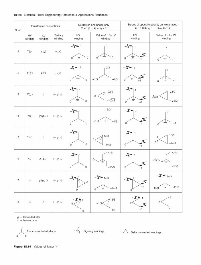
r = a factor that will depend upon the transformerconnections, as indicated in Figure 18.14
Vt = a prospective long-duration switching surge voltagethat may appear on the primary side. If an arrester isprovided on the primary side, this may be substitutedwith the switching surge residual voltage of thearrester, Vres
n = transformation ratio of the transformer (V1/V2)
Example 18.2Consider segment X of Figure 18.25 for the purpose of surgeprotection. The detailed working is provided in a tabular form,for more clarity, as under:
(A) Transformer voltage ratio
Connections
Rating
Approx. surge impedance from similar graphs as of Figure17.7(b) by extrapolation (obtain accurate value from themanufacturer)
Surge travels from higher voltage side of the transformerto the lower voltage side. Consider a surge protectionon the primary, with details as follows:
BIL of transformer from Table 13.2.
(Choosing a higher level, as the system being exposedto the atmosphere).
Primary side Vm
1 p.u.
Secondary side Vm
1 p.u.
Max. continuous operating voltage, MCOV ( / 3 );mV
HV side
LV side
(B) Characteristics of the arrester chosen from Table 18.9,class III; Standard rating, Vr(for detailed working and exact design parameters forselecting the arrester, refer to Example 18.3)
Max residual voltage (lightning) at 10 kA, Vres (8/20 ms)
Max. residual voltage (switching) at 1 kA, Vres (30/60 ms)
Max. residual voltage (FOW) at 10 kA, Vres (1/20 ms)
TOV capability for 10 s
132 /11 kV
60 MVA
50 W
Power frequency LIWLwithstand voltage
HV side 275 kVr.m.s 650 kV peakLV side 28 kVr.m.s. 75 kV peak
145 kVr.m.s.
145 2
3 = 118 kV¥
12 kVr.m.s.
12 2
3 = 9.8 kV¥
1453
= 83.7 kV
123
= 6.9 kV
120 kV
355 kV peak
294 kV peak
386 kV peak
203 kV peak (140% of Vm which is OK)
Considerations Parameters

Surge arresters: applications and selection 18/697
(C) Reflection of surges:
Zs of jumpers through which the surge will travel to thetransformer
As the transformer HV side is already protected by anarrester, it is not necessary to consider the influence ofrefraction of surges at point A, which is quite meagre inthis case.
The reflected wave will dampen the incidence surge by
(D) Surge transferences through the HV side of thetransformer
(i) Capacitive transference (initial voltage spike)
Assuming C
C Cp
p s + = 0.4
Vt = 2.5 p.u.
Since an arrester is provided at location A, it is appropriateto substitute Vt by Vres (FOW) = 386 kV peak
p = 1.15 for a lightning surge in a / transformer,
which is too high compared to LV side LIWL of thetransformer of 75 kVpeak (protective level not to be morethan 75 /1.2 = 62.5 kVpeak, Table 18.2), and calls foreither an arrester on the LV side too or provision of afew surge capacitors across the secondary windingssuch that,The value of C ¢ can be calculated if values of Cp and Csare known, which can be obtained from the transformermanufacturer.
NoteEven then a surge protection is essential for the tertiaryif the tertiary is provided.
(ii) Inductive transference
Assuming, p = 1 for a switching surge (in inductivetransference we have to consider long-duration surges only)
q = 1.8 for a switching surge
r =3
2 from Figure 18.14 for a /
transformer with surges of oppositepolarity appearing on two phases.
n = 145/12 = 12.1Vt = Vres (switching)
= 294 kV peak
and the power frequency withstand capacity of the LVwindings
\ Protective margin
Considerations Parameters
200 W
2 5050 + 200t¥ ¥V
= 0.4 Vt
V Vt t 50 – 20050 + 200
= – 0.6 ◊
VC
C CVtc
p
p st
+ p= ◊ ◊
\ Vtc = 0.4 ¥ 386 ¥ 1.15= 177.6 kV peak
C
C C Cp
p s+ + < 62.5
177.6¢
VVnti
t = p.q.r.
\ V ti = 1 1.8 3
2 294
12.1¥ ¥ ¥
= 37.9 kVpeak
= 28 kVr.m.s.
or 28 2 kVpeak
= 28 237.9
= 1.04
¸
˝Ô
˛Ô
which is too low. It is, however, possible to make it up by selecting the arrester on the primary side with a lower switchingVres. Consult the arrester manufacturer for it or provide an arrester on the secondary side also. Moreover, the responsefactor, q is considered very high, which may not be true in actual service and an arrester at the secondary side may notbe necessary in all probability. The BIL of the interconnecting cables and the terminal equipment on the secondary sidemust be at least equal to the capacitive and inductive transferences of the primary surges as determined above. If it is notso, the Vres of the primary arrester must be re-chosen or an arrester also provided on the secondary side.
18/698 Electrical Power Engineering Reference & Applications Handbook
S. no.
Transformer connections Surges on one phase onlyVr = 1 p.u, Vy = Vb = 0
Surges of opposite polarity on two phasesVr = 1 p.u, Vy = – 1 p.u, Vb = 0
HVwinding
Value of r for LVwinding
Value of r for LVwinding
HVwinding
Tertiarywinding
LVwinding
HVwinding
1 Y (g) y (g ) (–, y )
2 Y (g ) y (i ) (–, y )
3 Y (g ) D (–, y, D)
4 Y (i ) y (g , i ) (–, y, D)
5 Y (i ) D (–, y, D)
6 Y (i ) z (g, i ) (–, y, D)
7 D y (g , i ) (–, y, D)
8 D D (–, y, D)
1
0 0
1
0 0
1
0 –1
1
0 –1
1
0 0
2/3
–1/3 –1/3
1
0 –1
1
0 –1
1
0 0
1
0 0
1
0 0
1
0 0
1
0
0
10
0
2/3–1/3
–1/3
1
0
–1
1
0
–1
1
0–1
1/÷3
1/÷3 –2/÷3
1/÷3
0 –1/÷3
1
0 –1
1/÷3
1/÷3
–2/÷3
1/÷3
0
–1/÷3
1
0 –1
1/÷3
–2/÷3
1/÷30
–1/÷3
1
0 –1
1
0 –1
0
1
0 –1
2/3
–1/3 –1/3
g – Grounded stari – Isolated star
r
yb
Star connected windings Zig–zag windings Delta connected windings
Figure 18.14 Values of factor ‘r ’
3/2
– 3/2
3/2
– 3/2
3/2
3
1

Surge arresters: applications and selection 18/699
18.5.3 Effect of resonance
This applies to systems up to 245 kV, where inductiveimpedance is significant.
It is possible that at certain frequencies the capacitiveand inductive couplings of the transformer may resonate(XC = XL) (Section 24.4) during the course of a long-duration surge and give rise to yet higher voltagetransferences. For critical installations it is advisable toidentify (e.g. by TNA) the likely surges and theirfrequencies that may cause such a phenomenon to helptake corrective steps or modify the parameters C and Lof the transformer at the design stage.
An arrester basically is for equipment protection andmust be installed at all main equipment heads that areexposed to internal or external surges and whenever theamplitude of such surges, Vt, is expected to exceed theBIL of the equipment.
Figure 18.15 shows a power network with generation,transmission and distribution of power, illustrating theinfluences of the different kinds of surges that may appearin the system and which must be taken into account,while engineering a surge protection scheme for such asystem or a part of it.
18.6 Selection of a gapless surgearrester
To provide the required level of surge protection forequipment or a power system against possible transientfrequency voltage surges, ZnO gapless surge arrestersare the latest in the field of insulation co-ordination. Weprovide below a procedure to select the most appropriatetype and size of a ZnO surge arrester for the requiredinsulation co-ordination. Based on the discussions above,the following will form the basic parameters to arrive atthe most appropriate choice:
1 Service conditions: As for other equipment (e.g.motors, transformers or switchgears) a surge arrestertoo is influenced by unfavourable operating conditionssuch as noted in Table 18.4.
Unfavourable operating conditions will require aderating in the rating of a surge arrester or specialsurface treatment and better clearances. Refer to themanufacturer for the required measures and/orderatings.
2 Mechanical soundness: Such as strength to carry theweight of conductor and the stresses so caused, pressureof wind and, in extremely cold climates, the weightof ice.
3 Maximum continuous operating voltage (MCOV)Vc (rms): This voltage is selected so that the highestsystem voltage, Vm, as in column 2, Tables 13.2 or13.3, when applied to the arrester is less than or equalto the arrester MCOV, that is, Vc > Vm / 3.
4 The BIL of the equipment being protected (Section18.3).
5 The arrester’s nominal discharge current (In): Thisclassifies an arrester and is the peak value of a lightningcurrent impulse wave (8/20 ms) that may pass through
the arrester for which it is designed. It may be one ofthe following:
1.5, 2.5, 5, 10 and 20 kA
18.6.1 TOV capability and selection of ratedvoltage, Vr
TOV is considered only to select the MCOV and therated voltage, Vr, of the surge arrester. This is a referenceparameter to define the operating characteristics of anarrester. It plays no part in deciding the protective levelof the arrester, which is solely dependent on the transientconditions of the system, as discussed later. Vr is used tomake the right choice of an arrester and its energyabsorption capability to ensure that it does not fail underthe system’s prospective transient conditions.
To determine the level of TOVs and their duration, itis essential to analyse all the possible TOVs the systemmay generate during actual operation, and then decideon the most crucial of them, as shown in Table 18.5.Surge arrester manufacturers provide their TOV capabilitycurves in the shape of TOV strength versus duration ofthe TOV. A few typical TOV capability curves are shownin Figure 18.16(a) for distribution class and Figure18.16(b) for station class surge arresters. They indicatethe ratio between Vc and Vr which may vary frommanufacturer to manufacturer and is termed the TOVstrength factor K. For curve 18.16(b) it is typically
Vc = 0.8 Vr
Table 18.4 Standard operating conditions
Parameters Standard conditions
1 Ambient temperature1 –40∞C to +40∞C2 System frequency 48–62 Hz
3 Altitude2 1000 m
4 Seismic conditions Locations prone to experience anearthquake of magnitude M = 5 or aground acceleration of 0.1 g and more(Section 14.6)
5 Pollution/contamination3 Due to excessive rain, humidity, smoke,dirt and corrosive surroundings etc.,which may influence the arrester’sporcelain housing outer surface, hencethe insulating properties of the arrester
Notes1. Higher ambient temperature would mean higher leakage current
and higher losses (Figure 18.4(b)). Consequently it would callfor deration of ZnO blocks and the arrester. The manufacturer isthe best guide.
2. For higher altitudes extra clearances may be required in thedesign of the arrester housing. For every 100 m above 1000 marrester clearances may be increased by roughly 1%. Now alsothe manufacturer is the best guide.
3 During periodic inspections the atmospheric contamination canbe controlled by cleaning the housing by hot-washing the arresterwith de-ionized water or applying non-conducting, non-tracking,water repellent grease. Contact the manufacturer for procedure.

18/700 Electrical Power Engineering Reference & Applications Handbook
1
2
3
4
5
6
7
8
9
Isolated phase bussystem
15.75 kV LV HV
Jumper Jumper
Primary transmission(132, 220 or 400 kV)
LVHV LVHV
Jumper orcable
Jumper orcable
Mat
ch-li
neSecondarytransmission
Check forresonance effects
Check effectof surgetransferences:
(1) Capacitive
(2) Inductive
Type of arrester
* Values are only indicative to illustrate the likely reflections at different junctions.Obtain accurate values from the equipment manufacturers.
For critical installations up to 245 kV
Note:1. Transferences from LV to HV side are not significant and need not be considered.2. Transferences need not be considered when arrester is provided on the LV side.
For all voltages
For systems up to 245 kV
Station class
Outdoor OutdoorOutdoor OutdoorOutdoorIndoorIndoor
andpartly
outdoor
Station class
Occurrence oflikely surges:
Transferredsurges
Direct surges inboth directions
a
Conventional shape is shown, but amplitude as well as shape will varydepending upon the type of surge and ZS of line and equipment
Lightning, switching or steep fronted (FOW), depending upon thesystem voltage and switching conditions
(a) They may be transferred surgesfrom HV side or
(b) Direct surges on the LV side inboth directions
b
Shape
Type of surges
*ZS(W)
Effect ofreflections andrefractions[Not to beconsideredwhere arresteris provided]
Exposure toatmosphere
50 300 30 300 40 200 50
low v. high low v. highlow low
Mat
ch–l
ine
G
Figure 18.15 (Contd.)

Surge arresters: applications and selection 18/701
Figure 18.15 A power generation, transmission and distribution network and strategic locations for the surge arresters
1
2
3
4
5
6
7
8
9
Jumper orcable
Mat
ch-li
ne HV distribution(3.3, 6.6 or 11 kV)
HV LV HV LV
CableCable
LV Distribution(400/690V)
Cable orbus system LV loads
Surge protection on HV side isadequate to absorb direct surges.The transferred surges from HV sideto the LV side are too feeble to causeany harm. In case of staticswitchings, on LV side, however,surge arrester (SPD) will beessential, Section 6.13.2.
Check forresonance effects
Check effectof surgetransferences:
(1) Capacitive(2) Inductive
Type of arrester
* Values are only indicative to illustrate the likely reflections at different junctions.Obtain accurate values from the equipment manufacturers.
For critical installations up to 245 kV
Note1. Transferences from LV to HV side are not significant and need not be considered.2. Transferences need not be considered when arrester is provided on the LV side.
For all voltages
For systems up to 245 kV
Occurrence oflikely surges:
Conventional shape is shown, but amplitude as well as shape will varydepending upon the type of surge and ZS of line and equipment.
Lightning, switching or steep fronted (FOW), depending upon thesystem voltage and switching conditions.
(a) They may be transferred surgesfrom HV side or
(b) Direct surges on the LV side inboth directions
Shape
Type of surges
*ZS(W)
Effect ofreflections andrefractions [Not tobe consideredwhere arrester isprovided]
Exposure toatmosphere
50 100 2000
low high v. high
Mat
ch–l
ine
Outdoor Outdoor Outdoor orindoor
Indoor
Distribution classStation class
ba

18/702 Electrical Power Engineering Reference & Applications Handbook
Generalizing this for different conditions of TOV andmake of surge arrester,
Vc = K · Vr
For each kind of TOV and its duration, a correspondingfactor (K) is obtained and with this is determined therequired rating, Vr of the arrester. The most crucial TOVmay be selected as the rating of the arrester. If it is not astandard rating as in the manufacturer’s catalogue asshown in Tables 18.9 and 18.11, one may select the nexthigher rating available. A simple procedure is outlinedin Table 18.5 for a quick reference.
To determine TOV
The main causes of TOV, as discussed above, may beone or more of the following:
• Load rejection (Section 24.6.2).• Resonance and ferro-resonance effects (Sections 24.4
and 20.2.1(2)).
Table 18.5 Determining TOV
TOVs Cause of TOV OV factor Tripping timea TOV factor K from Figure 18.16(b) fora particular brand of surge arrester
TOV1 Ground fault(i) for a solidly grounded system £ 1.4 1 or 3 seconds 1.16 – for 1 second
1.13 – for 3 seconds(ii) For an isolated neutral system 1.73 10 seconds to a few 1.10 – for 10 seconds
hours and more 0.93 – for 2 hours
TOV2 Load rejection 1.1 1 second 1.16
a The higher the duration of fault, the higher will be the TOV factor of the arrester (Figure 18.16(b)) and the lower will be the protectivemargin and vice-versa. Depending upon the system operating conditions and criticality of the system and the equipment the arrester isprotecting, one should choose a more appropriate fault clearing time that the arrester shall have to withstand to provide a safe surgeprotection to the equipment and the system.
Volta
ge (
rms)
p.u
.(A
rres
ter
ratin
g)
1.35
1.3
1.2
1.1
1.0
.90.01 0.1 1.0 10 100 1000 10 000
Time
1
2
Curve – 1, No prior energy.Curve – 2, With prior energy.
Figure 18.16(a) TOV capability of a distribution class arrester
TOV
Str
engt
h Fa
ctor
(k)
1.3
1.2
1.0
0.9
0.8
0.7
0.93
1.161.13
1.1
VC (max.) = 0.8 x Vr
Cold condition (No trapped energy)
Hot condition (with trapped energy)
0.1 100.0 1000.0 10000.01.0 3.0 10.0
Time(s)
Figure 18.16(b) Typical TOV capability of a station class arrester
2 hrs.

Surge arresters: applications and selection 18/703
• Ground fault: Section 20.1. It is essential to know thegrounding conditions to determine the OV factor asbelow:
• Amplitude: As discussed in Section 20.1, groundingconditions, besides influencing the ground fault current,also raise the system voltage in the healthy phases. Itis established that for an isolated or resonant groundedsystem this can rise to 1.73 times and for a solidlygrounded system up to 1.4 times the rated voltage.When system parameters such as R0, X0 and X1 areknown a more accurate assessment of this factor canbe made by using OV curves as shown in Figures18.16(a) and (b).
• Duration: This will depend upon the ground faultprotection scheme adopted and may be consideredas follows:
(a) For a solidly grounded system: 1-3 seconds(normally, generation and transmission systemsare provided with a longer tripping time of up to 3seconds, and a distribution system still longer,say, up to 10 seconds).
(b) For an isolated, impedance or resonant groundedsystem: from a few minutes to several hours (whenit is 2 hours or more, it may be considered continuousfor the purpose of selection of an arrester).
• Short-circuit condition (Section 13.4.1(6)).
Based on these discussions and experience fromdifferent installations, the likely power frequency over-voltage (TOV) over a long period of operation for differentvoltage systems can be determined. For a more accuratevalue at a particular installation, it is advisable to carryout a system study. Generally, not more than onecontingency may occur at a time. However, dependingupon the type of system, which may be critical and moresensitive to load variations, a fault condition or frequentswitchings, more than one contingency may also beconsidered.
Example 18.3For a 400 kV system
Vm = 420 kV and
V c = 4203
= 243 kV
and minimum rated voltage V0 = 243/0.8 = 304 kV, when thesystem is not subject to any TOV. Consider a solidly groundedsystem, with a protective scheme of 3 seconds and theeventuality of load rejection, which may occur simultaneously:
\ Total TOV = 1.4 ¥ 1.1 = 1.54
From Figure 18.16(b), the TOV factor, K = 1.13 for 3-secondtripping.
\ Required = 1.54 2431.13rV ¥
= 331 kV (which is higher than 304 kV)
From the reproduced protective characteristics of this arrester,as in Table 18.11, the nearest next higher rating available is336 kV for a 420 kV system voltage. This is the basic ratingof the arrester which must be further checked for
• Whether its protective level can protect the BIL of thesystem and/or the equipment it is protecting, and
• its energy capability to clear safely the long-durationprospective voltage surges.
NoteIncreasing the TOV level, i.e. choosing a higher protectivelevel (Vres) of the arrester, may increase the life of the arresterbut will reduce the margin of protection for the protectedequipment. Selection therefore should be done judiciouslybearing all these aspects in mind.
18.6.2 Selecting the protective level ofthe arrester
For prospective voltage surges, as described in Table18.1, which may arise in the system during normaloperation the protective characteristics of the surge arrestermust be well below the BIL of the equipment at all points.For a minimum protective margin refer to Table 18.2. Itis the basic parameter of a surge arrester that defines itsprotective level. This is the voltage that will appear acrossthe arrester terminals and thus also across the equipmentbeing protected during a current discharge on theoccurrence of a voltage surge. It should be well belowthe BIL of the equipment under protection. Refer to theload diagram shown in Figure 18.17, for more clarity.
To determine this, consider the simple power circuitdiagram of Figure 18.18(a), where
Z1 = surge impedance of the line on which is connectedthe equipment to be protected from the source ofsupply up to the arrester
Z2 = surge impedance of the equipment to be protectedZt = surge impedance of the arrester at Vt
Sur
ge v
olta
ge (
Vt)
Vres
Vt
BIL
Protective margin = (BIL – Vres)
3
2
1
In
Discharge current
IV V
pt res
S =
– Z
1. Surge arrester protective characteristics.2. BIL of the equipment.3. Actual voltage surge.
Figure 18.17 Load diagram

18/704 Electrical Power Engineering Reference & Applications Handbook
Then applying Thevenin’s theorem,* the equivalent circuitcan be represented as shown in Figure 18.18(b). Onapplication of a voltage surge, the arrester will start
conducting at a certain voltage and carry a certaindischarge current. The voltage at which the conductionwill start is the impulse protective level of the arresterand is termed the residual voltage (Vres) of the arrester.By a manufacturer it is determined for each particulararrester to establish its protective level. It is establishedby drawing its elements’ I µ Vµ characteristics as shownin Figure 18.17 and drawing a load line on it to representthe characteristic of the prospective surge. It is drawnwith Vt as the ordinate and the current through theequipment Is (had there been no arrester) as the abscissa:
Then IVZs
t
s =
and the protective current through the arrester on adischarge
Ip =
Voltage absorbed or the voltage that isdischarged to ground
Impedance of the line and the equipment
= – t res
s
V VZ
whereVt = prospective surge voltage
Vres = residual surge voltage across the surge arrester(the impulse protective level of the arrester)which must be below the equipment BIL, witha sufficient protective margin,
and Zs = equivalent impedance of Z1 and Z2. (theimpedance of arrester, being too small, isignored)
Figure 18.18 Equivalent circuit applying Thevenin’s theorem
VtZ1 a
¢V Vt res =
G(a)
G
Vt
G
(b)
G
¢V Vt res =
Z2
G
Zt
Vres
Z2
Z1
Zs a
bG
Ip
Zt Vres
Z1 = Source impedanceZ2 = Impedance of equipment being protectedZt = Impedance of surge arrester. At Vt, it is negligible
Network withlinear circuitparametersand constantvoltage sources
ba
May be connectedto any other
network.
(a)(b)
E
Constantimpedance
Z
a
b
May
be
conn
ecte
dto
any
oth
erne
twor
k
Sin
gle
volta
ge s
ourc
e
Thevenin’sequivalent circuit
Z1
E1
Z3 Z2
Z3Z2
Z1
Z
I
s
E
(c) (d)
A simple power circuit Equivalent impedance
Figure 18.19 Thevenin’s theorem
*Thevenin’s theorem: This is one of the many theorems deducedmathematically to solve intricate circuits. This theorem hasestablished that it is possible to replace any network with linearparameters and constant phasor voltage sources, as viewed fromterminals, a and b, Figure 18.19(a), by a single phasor voltagesource E with a single series impedance Z, Figure 18.19(b). Thevoltage E is the same that would appear across the terminals a andb of the original network when these terminals are open circuited,and the impedance Z, is that viewed from the same terminals whenall voltage sources within the network are short-circuited. This canbe illustrated by the following example.
Consider the simple switching circuit of Figure 18.19(c). If wewish to find the current through the impedance Z3, on the closureof the switch, S, then;
I
ZE
, =
Voltage across this circuit ( ) before closing the switch,
Equivalent impedance , of the remaining circuit as seen from this switch (Figure 18.19d)
3
Z
= + 1
1 + 13
1 2
E
Z
Z ZÊË
ˆ¯
= +
+ 3
1 2
1 2
E
ZZ ZZ Z
◊
and the voltage across this circuit
EE Z
ZZ ZZ Z
13
31 2
1 2
=
+ +
etc.◊
◊

Surge arresters: applications and selection 18/705
The criteria to determine the safe protective level of anarrester are the BIL of the equipment, as shown in Table11.6 for motors, Tables 13.2 or 14.1 for switchgears,Table 32.1(a) for bus systems, and Tables 13.2 and 13.3for all other systems. Motors have a comparatively lowerBIL, but they are not connected directly on an outdooroverhead line, and are also reasonably shielded by theline transformer, switchgear and cables. Switchgear andthe bus systems, which may or may not be as shielded asthe motors, have comparatively a higher BIL than a motor.Their prescribed impulse withstand level for more exposedinstallations is given in Table 13.2, list II or III, while forshielded installations, it is lower and given in list I. Onemay notice that list I is still higher than a motor. On thisBIL is considered a suitable protective margin to providesufficient safety to the protected equipment as in Table18.2.
Protective characteristics of an arrester
The protective characteristic of a surge arrester is definedby its Vres, as a function of its nominal current (In) andthe time of rise, t1, in the impulse region as noted above.It is seen that the characteristic of an arrester varies withthe front time of the arriving surge. Steeper (faster rising)waves raise the protective level (Vres) of an arrester, asillustrated in Figure 18.20, and reduce the protectivemargin for the equipment it is protecting. Refer to Figure18.17 for more clarity. Figure 18.20 gives typicalcharacteristic curves of a leading arrester manufacturer,drawn for different magnitudes of current waves(In = 3-40 kA), Vres versus t1. From these curves can bedetermined the revised Vres during very fast-rising surgesto ensure that the arrester selected is suitable for providingan adequate protective margin during a fast-risingsurge.
Protective distance
The protective level as determined above is true only whenthe surge arrester is mounted directly on the protectedequipment (Figure 18.21). But this is seldom possible, asthere is usually a gap between the surge arrester and theequipment, due to arrester height, connecting leads andthe working gap required between the mounting of thearrester and the protected equipment. On the occurrenceof a voltage surge, while the arrester will conduct andabsorb the part of surge voltage that is in excess of itsprotective level (Vres), the residual voltage, Vres, will travelahead with the same steepness (r.r.r.v.) until it reachesthe equipment under protection. It may regain a sufficientsurge voltage to endanger the BIL of the equipment.Since the voltage will continue to rise as it travels ahead,as illustrated in Figure 18.22, the equipment will be subjectto higher stresses than the protective level consideredfor the surge arrester. The distance between arrester andthe equipment and the r.r.r.v. will determine the excessstress to which the equipment will be subject to. Thiscan be determined by
Vs = Vres + S.2.T (18.9)
Vs = actual surge voltage at the equipmentS = r.r.r.v. of the incoming wave in kV/ms
The factor 2 is considered to account for the reflectionof the incident surge at the equipment (Equation (18.3)): T = travelling time of the surge to reach the equipment
from the arrester terminals.If l is the distance in metres from the arrester terminals
to the equipment, then
T l = 100.3
s–3¥ m
Figure 18.20 Variation in protective level of an arrester with front time
160
150
140
130
120
110
100
90
80
112
Vre
s/V
10kA
(%)
Front time (ms)
0.1 0.2 0.3 0.4 0.5 0.8 1.0 2.0 3.0 4.0 5.0 6.0 8.0 10.00.6
I = 40 kA
I = 20 kAI = 15 kA
I = 10 kAI = 5 kA
I = 3 kA
The curves provide residualvoltages at different front timesin per cent of residual voltageat 10 kA 8/20 ms
�124

18/706 Electrical Power Engineering Reference & Applications Handbook
(considering the propagation of surge in the overheadlines at 0.3 km/ms, Section 17.6.6).
The longer the distance, l, the greater will be the severityof the oncoming wave which would reduce the protectivemargin of the arrester dangerously. Safe protectivedistances are normally worked out by the arrestermanufacturers and may be obtained from them for moreaccurate selection of an arrester.
Example 18.4For the arrester of the previous example,
Vm = 420 kV,Vr = 336 kV
Vres = 844 kV for a lightning surge protective margin at 20 kAdischarge current, from the manufacturer (Table 18.11)
It we consider the lightning surge with a steepness of 2000kV/ms, then for a total distance of, say, 8 m from the arresterto the equipment
V s
–3 = 844 + 2000 2 8 10
0.3¥ ¥ ¥
= 844 + 107
= 951 kV
If we maintain a protective margin of 20%, then the minimumBIL that the equipment under protection must have
= 1.20 ¥ 951
= 1141.2 kV
which is much below the BIL of the equipment (1300 kV) as
in Table 13.3. One can therefore safely select the arresterwith a higher rated voltage, Vr, at 381 kV and a Vres at 957 kV.
NoteA lightning surge protective level is found to be more stringentthan the switching surge or FOW protective levels. Hence, itis sufficient to check the protective distance requirement forthe lightning surge alone,
In such cases, care must be taken to reduce the protectivedistance, l, if possible, otherwise at some installationsequipment with a higher BIL may have to be selected or anarrester with a lower Vres, considered. Alternatively one mayhave to provide two arresters in parallel, which is also anacceptable practice.
18.6.3 Required energy capability in kJ/kVr
This is the energy the arrester has to absorb while clearinga switching surge. It also depends upon the distance ofthe arrester from the equipment it is protecting, asdiscussed above. The basic parameters that will determinethe required energy capability (I2Rt), are current amplitude,steepness, duration and number of likely consecutivedischarges. The energy capability of an arrester dependsupon the size of the ZnO blocks. By resizing these blocks,an arrester of a higher energy capability can be designed.Hence, an arrester with a higher kJ/kVr capacity will belarger than one with a lower kJ/kVr. ZnO blocks cangenerally absorb much higher energies at low currentswith long durations (i.e. power frequency stresses undernormal operation) than higher currents for short durations(i.e. surge voltage capacitive discharges). To select theright type of arrester the energy capability of the arresterin kJ must be determined by what it has to absorb onevery discharge. System studies through TNA or EMTPand past experience of similar other installations can bea good guide for the likely number of consecutivedischarges an arrester may have to perform at a time andthe likely energy release during a switching operation. Acomputer modelling can predict the arrester dischargecapabilities to match the arrester for the system switchingconditions. Generally, two consecutive discharges areconsidered to be adequate. Like other equipment, a surgearrester becomes too heated too during normal service,even when it is not conducting, due to its continuouscharging current, IZnO (Figure 18.4(a)) however smallthe loss content. When the arrester is conducting, thelevel of discharge current (I = kVµ) is a function of theprotective level of the arrester, Vres, and the rest of theseverity of the voltage surge is absorbed by the arrester.
The rating of an arrester is therefore defined in termsof its energy capability to absorb at least the requiredenergy on each discharge and the number of dischargesthe arrester may have to perform in quick succession.IEC 60099-4 has prescribed the minimum energycapability that an arrester must possess, at each discharge.The graphs in Figure 18.23 indicate these levels fordifferent classes. It may be noted that an arrester with ahigher energy capability level will mean less strain orrisk of failure for the arrester, but at a higher cost. Abrief procedure to determine the energy level that thearrester may have to absorb on each discharge is givenbelow.
Of the three types of surges noted earlier (Table 18.1)
Figure 18.22 Effect of distance on the protective level
Sur
ge V
olta
ge
Ext
ra s
tres
sbe
caus
e of
dist
ance
Vt
BIL
Vres
Tt1 Time
Surge arrester
G
Protection to benear the equipmentand not on the line
Figure 18.21 Ideal location of a surge arrester
G

Surge arresters: applications and selection 18/707
which the arrester may have to sustain and absorb, theswitching surge energy would be the maximum that wouldexist for the longest duration, compared to lightning orvery steep-fronted FOWs (Section 17.3) which are of veryshort duration. Normally, therefore, a switching surge aloneis considered for this purpose. During the operation of asurge arrester, a part of the surge, equivalent to the protectivelevel of the surge arrester, will conduct and appear as theresidual voltage across the arrester in terms of its protectivelevel and the rest would be absorbed by it. What isabsorbed would determine its absorption capability. Fora switching circuit, as shown in Figure 18.18(a), this canbe theoretically determined by:
WV V
ZV T n =
( – ) 2 10t res
sres
–3◊ ◊ ◊ ¥ (18.10)
where W = energy absorbed in kWs or kJ (1 W = 1 J/s) Vt = prospective switching surge crest voltage (kV)Vres = Switching surge residual voltage of the arrester (kV)
NoteAs in IEC 60099-4, the lowest value of Vres must be consideredwhich occurs at a lower switching surge discharge current,such as a switching surge, Vres, at 1 kA, 2 kA, 3 kA, etc.Tables 18.9 and 18.11 illustrate this.
Zs = surge impedance of the affected line.T = travelling time of the switching surge from the arrester
to the equipment in ms. The factor 2 is considered toaccount for the reflection of the incident switchingtransient wave at the equipment (Equation (18.3)).The virtual duration of the surge peak, considered inTable 18.6, also corroborates this.
n = number of consecutive discharges. The energycapability of an arrester is its capability to discharge
three such switching surges at an interval of 50-60seconds each (IEC 60099-4). But since the thermaltime constant of ZnO blocks is high (in the rangeof 60-100 minutes) the time interval of 50-60seconds does not really matter, and it may beconsidered as three consecutive discharges for allpractical purposes. It is, however, seen that in service,even two consecutive discharges are rare and threemay never occur. It is, therefore, sufficient toconsider two consecutive discharges for selectingan arrester. The normal practice by leadingmanufacturers is to specify only the total energycapability for which their arresters would be suitableduring consecutive discharges.
Apparently a higher level of Vres would mean a lowerlevel of energy absorption by the surge arrester in termsof Vr. For an excessive level of W required, it is better toselect a higher Vr. If it jeopardizes the required protectionlevel, then select another type of surge arrester with ahigher energy capability.
To determine W from the above it is essential to knowthe system parameters. Based on system studies ofdifferent voltage systems (transmission lines particularly)many data have been collected. Typical data as suggestedby IEC 60099-4 are provided in Table 18.6 for a generalreference. For secondary transmission or primarydistribution networks up to 245 kV too, where a lightningsurge forms the basis of selection for the protective level(Vres) of the arrester, only the switching surge must beconsidered to determine energy capability.
Example 18.5 in Section 18.10 illustrates the procedureto determine the energy capability requirement of anarrester for a particular system. The ultimate selection ofan arrester is a compromise between its protective level,Vres, TOV capability and energy absorption capability.
18.7 Classification of arresters
These are classified by their nominal discharge currentsIn (8/20 ms) and surge energy absorption capability duringa discharge (kJ/kVr). Each discharge current is assigneda system voltage according to IEC 60099-4, as noted in
Figure 18.23 Classification of arresters in terms of specific energykJ/kVr versus Vres/Vr as in IEC 60099–4
Class 5
Class 4
Class 3
Class 2
Class 1Spe
cific
ene
rgy
kJ/k
Vr
Class 4
4
7
6
5
3
2
1
0
1.951 2 3 3.5
Vres / Vr
Table 18.6 Typical parameters of a transmission line
Line Line discharge Surge Virtual Approx.discharge class of impedance duration of surgecurrent arrester of the line peak amplitude(kA) Zs(W) 2.T a(ms) Vt(kV)
10 1 4.9 Vr 2000 3.2 Vr10 2 2.4 Vr 2000 3.2 Vr10 3 1.3 Vr 2400 2.8 Vr20 4 0.8 Vr 2800 2.6 Vr20 5 0.5 Vr 3200 2.4 Vr
Based on IEC 60099-4a These are the line discharge test values to test an arrester, asrecommended by IEC and have been considered here for the purposeof selection of an arrester. Refer to Example 18.5.

18/708 Electrical Power Engineering Reference & Applications Handbook
Table 18.7. The energy capability of an arrester willvary with the over-voltage conditions of the system. Itis therefore essential to ensure that the arrester chosenhas sufficient capability to sustain the required systemTOV and surge conditions during long years of operation.IEC 60099-4 has also recommended the line dischargeclasses of arresters, based on the required energy levelin kJ/kVr and the ratio of Vres/Vr (Figure 18.23). Theenergy capability of a normal arrester produced by leadingmanufacturers is generally higher than recommendedby the IEC for a particular class of arrester. The lastcolumn of Table 18.7 and Figure 18.23 recommend theminimum energy capability of different classes ofarresters. The class of arrester for a system, particularlyfor heavy duty, can be easily chosen with the help ofthese figures for a required level of kJ/kVr and a ratioof Vres/Vr. Arresters classes 1 to 5 are regarded as heavyduty and classified as station class by ANSI/IEEE-C62.11.For light duty, a distribution class may be selected toeconomize on cost. The nominal current, rated voltage,Vr, level of protection, Vres, and energy capability forsuch arresters are indicated in Table 18.8 for a particularmanufacturer.
The subsequent Example 18.5 will provide a simplestep-by-step procedure to select an arrester for a particularapplication >245 kV.
The application and rating of an arrester is a matter ofsystem study and systematic insulation co-ordination,likely discharge current during a possible lightningdischarge at the location of the installation and experiencegathered from similar installations. Different countriesmay adopt different practices, depending upon the stabilityof their networks and the type of surges that may ariseduring the course of operation. Hence, only broadguidelines can be given to choose an arrester. The rest isa decision by the application engineer and his experienceof power networks.
18.8 Application of distributionclass surge arresters
The application of these arresters is guided by theirfollowing basic characteristics:
Gapped Surge Arresters1. The gapped arresters possess a low-energy handling
capability and hence cannot be applied for installationsand equipment that may be subject to long-duration(250/2500 ms) switching surges such as motorsrequiring high-energy handling capability. They are,however, suitable to withstand an FOW or a transferredsurge, as this requires a very low energy handlingcapability which such arresters can handle.
2. They also pose limitations for installations that connecta number of cables, reactors and capacitor banks, asthese also require a higher energy handling capability.
3. They offer a relatively higher Vres and may generallynot be suitable for protection of equipment that havea low BIL. The BIL of rotating machine or a dry typetransformer for instance, may fall lower than the Vres ofthe arrester chosen as per the Vr and the equipment mayremain unprotected, unless the arrester is custom-builtto suit the BIL of a motor. For clarity see Example 17.5.
4. Basically they are light-duty arresters and must beinstalled at locations that are not directly exposed tolightning strokes.
These arresters are therefore employed for surge protectionof installations and equipment that are not so critical asto cause a shutdown of the power system. Likelyapplications may be small distribution networks andequipment such as distribution transformers, feedingresidential or small industrial loads, not directly exposedto the atmosphere and hence to direct lightning strokes.
Table 18.7 Classification of arresters
Arrester line discharge Nominal discharge current Rated voltage Typical energy capability of class at lightning impulse (8/20/ms) Vr arresters produced
kAAs in ANSI As in IEC 60099-4 as in IEC 60099-4
kV kJ/kVr
Station class 1 10a Generally more than recommendedas in graphs of Figure 18.23
2 10a 3 10a
4 20a
5 20a
Distribution – 5 up to Not significant for the purpose ofclass 11 arrester selection
– 2.5c up to– 1.5c b
NotesaSelection of any arrester will depend upon the duty it has to perform (light duty for indoor and heavy duty for outdoor installations) andthe required energy absorption capability.bYet to be defined by IEC 60099-4, but generally for low-voltage systems. Not often in use for power system applications.cThe application of such arresters is noted in Section 18.8.
765 kV and above 362 < Vr £ 765
up to 420 kV 3 £ Vr £ 362
¸
˝Ô
˛Ô¸
˝Ô
˛Ô
¸
˝Ô
˛Ô¸
˝Ô
˛Ô
¸
˝Ô
˛Ô

Surge arresters: applications and selection 18/709
Such installations are reasonably shielded, as wheninstalled within a city. Even 5 kA gapped distributionclass arresters may not be suitable for distribution linesrunning through long open terrains, such as for ruralelectrification and are therefore exposed to direct lightningstrokes and their higher severities.
Therefore, for power applications that are adequatelyshielded minimum 5 kA surge arresters are in practice.1.5 and 2.5 kA arresters hardly have any application dueto their frequent discharges and rapid failures and mostmanufacturers have since discontinued the manufactureof the same.
Gapless metal oxide varistors (MOVs)
These are heavy-duty distribution class surge arrestersand possess high energy absorption capability and suitablefor distribution systems discussed above. Tables 18.8and 18.8(a) provide typical data up to 11 kV surge arresters,widely employed for the distribution of power that canbe through an overhead or an underground distributionnetwork. For higher ratings one may consult the
manufacturer or their data sheets. These arresters aresuitable for protection against lightning surges as well asswitching surges. Since distribution is not below 11 kVthese arresters too have little application below 11 kVexcept on the secondary side of a sub-distributiontransformer 33 or 11 kV/ 3.3 or 6.6 kV feeding utilitiesand other loads at 3.3 or 6.6 kV such as to protect furnaces,capacitors, reactors and rectifier circuits even motorsfrom transferred surges.
18.9 Pressure relief facility
A surge arrester is a sealed unit to save it from allatmospheric hazards. It is normally filled with air.Explosions of surge arresters have been noticed duringservice. Explosion of a porcelain housing is dangerous,as the shell splinters can cause great damage to nearbybushings, insulators and other equipment and alsomaintenance personnel if working in the vicinity.
It is possible that ZnO elements may break down with
Table 18.8 Technical data of metal oxide distribution and station class lightning arresters (MOVs)
Parameters Distribution Station classa
class (for motor protection)
1 Rated maximum system voltage (Vm) (50 Hz) kV r.m.s. – 7.2 3.62 Rated voltage kV r.m.s. 9 6 3
3 Nominal discharge current (8/20 msec.) kA peak 5 10 10
4 MCOV kV r.m.s. 7.65 5.5 2.8
5 Max. residual voltage Vres (kV peak) at:(a) Lightning current impulse (8/20 ms) peak
(i) 2.5 kA 29 – –(ii) 5 kA 30 17.7 9.31(iii) 10 kA 33 19.0 10.0(iv) 20 kA 36 21 11.5
(b) Switching surge residual voltage(1.0 kA, 30/60 mmmmms) kV peak 30 15.3 8.1
(c) Steep current impulse (1/2 mmmmms) 5 kA peak 33 – –10 kA peak 40 21.5 11.5
6 Long duration discharge class: (defines the energy capability)c
(a) Current A peak 75 – –(b) Virtual duration of peak ms 1000 – –
7 High current (4/10 ms)d kA peak 65 100 1008 Temporary power frequency over-voltage capability
(kV r.m.s.),(i) 0.1 second 10.5 b
(ii) 1.0 second 10 b
(iii) 10.0 seconds 9.5 b
(iv) 100.0 seconds 9.2 b
Courtesy: Elpro International
NotesaFor 11 kV motors refer to Table 18.9.bTOV capability of the arrester is provided by the manufacturer as standard practice, either in the form of voltage versus time data, as given
in column 1, or a graph. A typical graph is shown in Figure 18.16(a).cTo assess the loss parameter of the arrester, under normal operating conditions (power frequency), the following data, typical (for the above
arresters) may also be obtained from the manufacturer. Also refer to Section 18.2. Reference current: 1.0 mA Leakage current at MCOV,
(i) Resistive 3.0 mA(ii) Capacitive 0.8 mA
dTo identify the suitability of the arrester on direct lightning strokes.

18/710 Electrical Power Engineering Reference & Applications Handbook
time due to thermal cracking as a result of system TOVsoccurring frequently or existing for long durations, orwhile clearing a lightning or a switching surge and evensubsequent to that. Breakdown of ZnO elements intosplinters may collide with the main porcelain housing.But most damage is caused by a flashover between theZnO elements and the side walls of the housing, whichmay result in puncture or crackdown. It may lead to acascading effect and cause an eventual short-circuit withinthe housing and result in a very heavy ground fault current( / 3 )1V Zg◊ through it.
The fault current may cause a flashover and rise inthe internal temperature and pressure of the housing. Itis extremely important to make provision to release thispressure, otherwise it may lead to an explosion of thehousing, scattering splinters like bullets in the vicinity.This is dangerous and must be avoided. The pressurerelief capacity must be such that there will be no violentexplosion of the housing during a failure. Although itmay shatter, the arrester’s fractured pieces should notfall beyond a circle of a radius equal to its height,somewhat similar to the properties of safety glass windscreens used in a car. International specificationsrecommend that on a pressure build-up, the hot gaseswill escape through the pressure relief diaphragm or thehousing may simply collapse as a result of thermal shock.An arrester that is vented must be quickly replaced.
This is achieved through a pressure relief system in theform of a pressure relief diaphragm at the top of the housing.The pressure relief system is designed for the system faultlevel. To test the pressure relief system, IEC 60099-4 andIEC 60099-1 have also specified the test current of thesame magnitude as the fault current of the system, but fora very short duration, of the order of 0.2 second or so.This brief period is enough to burst or shatter the housingof the arrester, hence a longer duration is of no relevance.
The practice for heavy-duty arresters is to eliminatethe causes of internal flashover between the ZnO elementsand the housing at the manufacturing stage. Differentmanufacturers have adopted different methods forachieving this. One such method is providing a barrierof an insulating material not affected by heat and arcing,
such as an FRP (fibre reinforced plastic) tube betweenthe housing and the ZnO elements.
18.10 Assessing the condition ofan arrester
To ensure adequate safety for a system and its terminalequipment against over-voltages and voltage surges it isessential to ascertain the soundness of the arrester atregular intervals. It should be possible to do this when itis in service without taking it off from the lines with thehelp of available instruments noted next. If deteriorationof the ZnO elements is detected it may need more frequentfuture services or replacement of the arrester. It can nowbe planned well in advance. The requirement is similarto ascertaining the condition of power capacitors whenin service (Section 26.2). Like a capacitor, an arresterdeteriorates too with time due to degradation of thedielectric strength of its ZnO elements.
ZnO is a highly non-linear resistor element. The successof an arrester will depend upon its low, continuous resistiveleakage current Figure 18.4(a) to maintain low loss andlow heating over years of continuous operation. Whenthe ZnO blocks start to deteriorate which is a slow processas discussed earlier, the leakage current starts rising fromits original level. The rise in current is rich in thirdharmonic component due to the non-linear characteristicof the ZnO blocks. Other reasons for degradation in thedielectric properties and a rise in current may be one ormore of the following:
• Ingress of moisture through the seals, although Silicagelis provided beneath the arrester sealing to absorb themoisture.
• Failure of ZnO elements during or after clearing afew surges.
• Premature ageing of the ZnO elements.• Temperature variations. The rise in Ir is rapid at higher
operating temperatures (Figure 18.4(b)).• Frequent system voltage variations.• Being continuously energized.
Table 18.8a Technical data of 5kA gapless metal oxide distribution class surge arresters (MOVs)
Rated voltage (Vr) (kV rms)
Maximum continuous operating voltage (kV rms)(MCOV)
Maximum residual voltage (Vres) at lightningcurrent impulse 8/20 ms 2.5kA (kV peak)
5kA (kV peak)10kA (kV peak)
Maximum steep current impulse residual (kV peak)voltage at 5 kA 1/20 ms impulse
Insulation withstand at 1.2/50 ms impulse (kV peak)
Long duration discharge current at 1000 ms (A)impulseEnergy absorption capability at 4/10 ms (kJ/kVr)impulse
3
2.55
8.69.410.3
10.3
95
75
2.8
5
4.25
14.315.717.2
17.2
95
75
2.8
6
5.1
17.318.820.7
20.7
95
75
2.8
9
7.65
25.928.231.0
31.0
95
75
2.8
10
8.5
28.831.334.4
34.4
95
75
2.8
12
10.2
34.637.641.3
41.3
95
75
2.8
Courtesy: Alstom (Now Areva)

Surge arresters: applications and selection 18/711
A rise in leakage current is not desirable and isindicative of deterioration of the ZnO blocks, which maylead to failure besides extra losses till such period thearrester remains in service. It is therefore necessary tomonitor the leakage current and detect a possible failurebeforehand and take corrective steps in advance. Themaximum safe leakage current is specified by the arrestermanufacturer as a relation between Ir and its third harmoniccomponent, I3r. I3r is expressed in terms of IZnO as discussedlater. It varies with deterioration of the arrester and isused as a reference parameter to assess the arrester’scondition. As the actual leakage current measured throughIZnO starts rising and approaches the maximum leakage
current in healthy condition closer monitoring of thearrester becomes essential, to avoid an abrupt failure orexplosion. Refer to Table 18.10 to monitor the conditionof the arrester. To measure Ir, let us analyse the basiccircuit of an arrester as considered in Figure 18.5, where
Ir = loss component and is about 5-20% of Ic undernormal operating conditions. Any change in itsvalue will contain a third harmonic componentbecause of its non-linearity. It will vary withsystem voltage and operating temperature.
Ic = leakage capacitive component leads Ir by 90∞. Italso depends upon the system voltage and the
Table 18.9 Protective characteristics of gapless station class surge arresters for a nominal discharge current of 10 kAa
1 System voltage (50 Hz)kV 420 245 245 145 123 72 36 36 24 12 12
2 Rating of surgearrester (at thereference current) kV 390 216 198 120 96 60 36 30 18 12 9
3 Discharge class III III III III III II II II I I I4 Energy dissipation
capability cumulativeoperation (kJ/kVr) 10 10 10 6.5 6.5 4.5 4.5 4.5 2.5 2.5 2.5
5b High current impulsewithstand of 4/10 mswave shape kA 100 100 100 100 100 100 100 100 100 100 100
6 Reference current ofthe arrester at ambienttemperature mA 5 5 5 3.25 3.25 2.25 2.25 2.25 1.5 1.5 1.5
7 Components of thecontinuous leakagecurrent at COVResistive mA peak 400 400 400 400 400 400 400 400 400 400 400Capacitive mA peak 1500 1500 1500 1500 1500 1500 1500 1500 1500 1500 1500
8 Watt loss at MCOV perkV of rated voltage
W/kA 0.25 0.25 0.25 0.25 0.25 0.25 0.25 0.25 0.25 0.25 0.259 Maximum continuous
operating voltagekV r.m.s. 303 178 168 102 81 52 30.5 25.5 15 10 7.65
10 Max. residual voltageat lightning impulse of8/20 m s wave kV peak
5 kA 860 567 518 333 249 162 103 85 60 38 3310 kA 900 602 550 355 264 175 110 90 65 40 3520 kA 957 668 610 390 304 202 128 104 75 46 41
11 Maximum residual voltageat switching currentimpulse of 30/60 ms,
1 kA 780 496 457 294 221 138 87 71 52 32 2812 Maximum residual
voltage at steep-fronted impulse (1/20ms, IEC 60099-4) at
10 kA 1050 654 600 386 288 202 124 101 73 45 4013 Temporary power frequency
overvoltage capability(a) 0.1 second kV peak 705 397 364 220 156 97 58 48 29 19 14(b) 1.0 second kV peak 580 382 350 212 149 93 56 46 28 18 14(c) 10.0 seconds kV peak 565 367 336 203 142 89 53 44 26 17 13(d) 100.0 seconds kV peak 550 305 280 169 135 84 51 42 25 16 12
Courtesy: Elpro International
a These are typical figures and can be varied by the manufacturer to suit an application.b To identify the suitability of the arrester on direct lightning strokes.

18/712 Electrical Power Engineering Reference & Applications Handbook
operating temperature. It is, however, independentof Ir and remains almost unaffected by thedeterioration of ZnO blocks, i.e. change in Ir.
IZnO = Total leakage current of the arrester. It also riseswith system voltage and operating temperature.Under healthy conditions this current is verylow (in the range of mA).
Ideally, measuring the variation in IZnO should be enoughto determine the condition of an arrester. But it is not so,as it does not provide a true replica of Ir for the followingreasons:
• System voltage harmonics With deterioration ofthe arrester, Ir rises and so does its third harmoniccomponent, because of non-linearity of the ZnO blocks.IZnO therefore also measures the harmonics present inthe system voltage, particularly the third harmonic.The system harmonics are also magnified by theleakage capacitances of the arrester. Since an arresteris connected between a phase and the ground, thethird harmonic of the system finds its path throughthe grounded arrester and distorts the third harmonicof the ZnO blocks caused by their deterioration.
• Uneven distribution of C along the arrester(Lundquist et al., 1989)
• Pollution by the surroundings, such as by dirt andingress of moisture. In normal conditions this alsoraises Ic and IZnO and
• Corona effect All such factors may influence the Irand IZnO in different proportions and be detrimental inassessing the actual variation in Ir through IZnO. IZnOtherefore cannot be regarded as a true replica of Ir.Monitoring of IZnO may not accurately assess the actualcondition of the arrester. To use IZnO to assess the con-dition of an arrester, it is essential to separate Ir from it.
The greatest effect of ageing is reflected by the variationin its resistive current, which is rich in the third harmonic.Variation in Ir is used in assessing the condition of anarrester. By conducting laboratory tests to determine thecharacteristics of an arrester, we can establish a ratio betweenthe total leakage current, IZnO and the content of Ir, toassess the condition of the arrester. If we can monitor thiscurrent, we can monitor the condition of the arrester. Belowwe discuss briefly one such method by which thiscomponent can be separated out.
Leakage current monitor
(A diagnostic indicator of metal oxide surge arresters inservice).
NoteInstruments operating only during discharges are basically surgecounters and can only indicate the number of discharges. Theyprovide no information on the condition of the arrester.
To measure the resistive leakage current, Ir, alone is acomplex subject. However, there are a number of methodsto determine this. IEC 60099-5 mentions a few methodsby which the resistive leakage current, Ir, can be measuredthrough IZnO. The main problem faced in all these methodsis the presence of a system voltage third harmonic thatfinds its way through the grounded arrester and shows upin IZnO. Therefore, unless the system voltage third harmonicis eliminated from IZnO, it will not provide a true replicaof the arrester’s condition. Below we discuss one betterrecognized method (See Lundquist et al., 1989) by whichan attempt is made to separate out the system voltagethird harmonic from IZnO. The method is based on extractionof Ir by third-order harmonic analysis of IZnO. This isachieved by providing an electric field probe located atthe grounding end of the arrester. The probe compensates
Table 18.10 Logbook to monitor the condition of an arrester when in service
Date of measurement Healthy IZnO(h) max.a Actual measurement of IZnO(a) Likely condition of the arrester
provided by the arrester at siteb
manufacturermA mA As % of IZnO(h)
1st year 70 28 Good3rd year 90 36 Good5th year 115 46 Good7th year (December)c 160 64 Sign of deterioration
8th year (May)c 220 88 Sign of rapid deteriorationRecommended for servicing aroundthis time
8th year, (November)c 300 120 Requires servicing or replacement
aIZnO(h) = maximum leakage current in normal conditions.bIZnO(a) = actual leakage current measured at site.cCloser monitoring recommended.The above figures are purely hypothetical.
NoteMonitoring by such an instrument can be carried by installing it permanently or by using it as a portable instrument. Even when connectedpermanently, the measurements are taken at long intervals for short durations for periodic checks of the arrester. The table suggests onlylikely check periods, which may vary with environmental conditions and the quality of the system voltage. Higher discharges or frequentswitchings of the line breakers, for instance, may deteriorate the ZnO blocks more quickly and require more frequent readings than forsystems having lower discharges or switchings.
¸
˝
ÔÔÔ
˛
ÔÔÔ
250

Surge arresters: applications and selection 18/713
the third harmonic present in the system voltage so thatthe current measured at the ground end of the arrestercontains only the third harmonic of Ir. Harmonics, otherthan the third even if they are present in the system orIZnO, are of little relevance, as the instrument analysesonly the third harmonic.
The instrument separates out Ir and Ic and provides adirect reading of Ir and hence the condition of the arrester.Refer to Table 18.10 providing a brief procedure to monitorthe condition of an arrester through such a monitor.
A typical layout of such an instrument and itsaccessories is shown in Figure 18.24(a). It consists of:
• Leakage current monitor – this can be connectedpermanently for continuous reading or periodicmonitoring. The normal practice is to measure onlyperiodically for a short period to take averagemeasurements on an hourly, daily, monthly or yearlybasis. When not connected permanently, the instrumentcan also be used as a portable kit to monitor thecondition of other arresters installed in the vicinity.
• Field probe – to compensate the third harmonic ofthe system voltage to make the IZnO free from thethird harmonic of the system voltage. This method ofIr measurement therefore provides more accurate andcloser monitoring of the arrester.
• Clip-on CT – to measure IZnO and is mounted at thegrounding end of the arrester.
• Current probe – to measure the third harmoniccomponent of Ir. It is then converted to actual Ir fromthe ZnO characteristic data provided by the arrestermanufacturer, Ir versus I3r, corrected to the siteoperating temperature and voltage. The value of Ir isthen used to assess the condition of the arrester.
• Adapter (connector) – to connect the CT with theinstrument.
Figure 18.24(b) illustrates the use of a leakage current
Power line
ZnO blocks(Showingsectional view)
Leakage groundcapacitancescausing leakagecurrent
Porcelain discs
Leakage currentmeasuringinstrument
IZnO
CT
IC
Ir
Vm
3
IZnO – Surge arrester leakage current free from system voltage 3rdharmonic
IC – Free from system voltage 3rd harmonicIr – With 3rd harmonic current component
I I IZnO C r = +
Figure 18.24(b) Measuring leakage current through an arresterwhen in service.
Figure 18.24(a) General arrangement of a Leakage Current Monitor (LCM) (Courtesy: TransiNor As)
Clip-on currenttransformer
Insulatedarrester base
Current probe
Field probe
LCM II
PC normally used in theoffice only

18/714 Electrical Power Engineering Reference & Applications Handbook
monitor. The instrument can be used to display or monitoron a computer remotely and store data at intervals asrequired to provide diagnostic information. Now it iseasier to take corrective measures in time. The instrumentcan also be programmed to give an alarm at a presetvalue of Ir when the actual operating conditions exceedthis.
Example 18.5Step-by-step selection of a surge arrester for the protectionof equipment mounted on a 400 kV transmission line as inFigure 18.25.
Considering conditions (i) and (ii) occurring at the sameinstant,
\ total TOV = 1.4 ¥ 1.1 = 1.54 for 3 seconds
TOV factor as in Figure 18.16(b), K = 1.13
\ V r = 1.54 2431.13
= 331 kV¥
For this voltage, we have selected a Class 4 arrester, whichhas the nearest next higher rating as in Table 18.11 as
Vr = 336 kV
As regards the primary selection of the arrester, it is completeat this stage. But this selection must be checked for its adequateprotective level and the energy absorption capability.
(A) Checking for the protective level
For this rating, the arrester protection levels are:
• Vres(max) for a switching impulse wave of 1 kA for thepurpose of energy capability = 654 kV.
• For switching impulse protective margin at 2 kA = 676 kV= Vt (switching).
• Vres(max) for a 20 kA lightning impulse (8/20 ms) = 844 kV.• Vres(max) for a 0.6 ms FOW from Figure 18.20 = 1.24 ¥
844 = 1047 kV = Vt (FOW).BIL of the equipment to be protected, from Table 13.3 listI (considering the lower side to save on the cost ofequipment)
• For switching surges = 950 kV• For lightning surges = 1300 kV• For very fast-rising surges (FOWs) = 1300 kV (assumed).
This value must be obtained from the manufacturer ofthe equipment to be protected.
Considerations Data
Nominal system voltage (V I ) 400 kV (r.m.s.)Maximum system voltage (Vm) 420 kV (r.m.s.)
In per unit (p.u.) 1 p.u. = 420 2
3¥
= 343 kVMaximum continuous operating
voltage (MCOV), V
Vmc
3 =
4203
= 243 kV
(max.)
Temporary overvoltages (TOVs) OV trippingas in Table 18.5 factor time
(i) Due to a ground fault for asolidly grounded system witha GFF of 1.4 TOV1 1.4 3 sec
(ii) TOV due to load rejectionTOV2 1.1 1 sec
(iii) TOV due to a short-circuitfault TOV3 1.3 0.5 sec
Table 18.11 Protective characteristics of a gapless station class surge arrester for (1) Line discharge class 4, and (2) Singleimpulse energy capability = 7 k.J/k.Vr
System Rated Max. MCOV TOV capability Maximum residual voltage with current wavevoltage voltage cont. as in for
operating ANSIvoltage tests Switching surgesa Lightning surges 8/20 ms(MCOV)
1s 10 s 1 kA 2 kA 3 kA 5 kA 10 kA 20 kA 40 kAkVr.m.s kVr.m.s kVr.m.s. kVr.m.s kVr.m.s kVr.m.s kVpeak kVpeak kVpeak kVpeak kVpeak kVpeak kVpeak
420 330 264 267 383 363 642 664 680 718 759 829 911336 267 272 390 370 654 676 693 731 773 844 928360 267 291 418 396 701 724 742 783 828 904 994
372 267 301 432 409 724 748 767 810 856 934 1027378 267 306 438 416 736 760 779 823 870 949 1044381 267 308 442 419 741 766 785 829 877 957 1052
390 267 315 452 429 759 784 804 849 897 979 1077396 267 318 459 436 771 796 816 862 911 994 1093420 267 336 487 462 817 845 866 914 966 1055 1160
aAny impulse with a front time longer than 30 ms.Courtesy: ABB

Surge arresters: applications and selection 18/715
(B) Checking for the energy capability
It is sufficient to check this for systems of range II (>245 kV)alone, as the energy requirements for systems of range Imay be moderate. The lightning surges are found to be moresevere than the switching surges. But since the lightning surgesare of short duration, they dissipate very low energy and anormal arrester is capable to absorb much more than this.The energy capability for long duration switching surges ischecked in the following paragraphs
W (for each discharge)
= – t res
s
V VZ . Vres.2.T. 10–3 kJ (18.10)
To assess the energy capability of the arrester more realistically,let us consider the established system parameters as in Table18.6 to determine the maximum energy discharge throughthe arrester,where
Vt = 2.6Vr
= 2.6 ¥ 336= 874 kV
Vres = 654 kV (for In = 1 kA as per IEC 60099-4)
Zs = 0.8Vr
= 0.8 ¥ 336
= 269 W
2.T= 2800 ms
NoteThe time of travel from the point the lightning strikes on theoverhead lines to the arrester, considering a line length ofapproximately 420 km and speed of propagation of the surgeas 0.3 km/ms,
T = 4200.3
= 1400 sm
Accounting for reflections, the total time must be consideredas 2 ¥ 1400 or 2800 m s. Accordingly, 2800 ms is specified byIEC 60099–4 for the testing of the arrester under the worstconditions. The arrester must also have the capability tosuccessfully discharge the prospective surge under suchconditions.
\ W = (874 – 654)
269 654 2800 10 kJ–3¥ ¥ ¥
= 220269
654 2800 10 –3¥ ¥ ¥
= 1498 kJ or 1498336
= 4.46 kJ/kVr
Say, 4.5 kJ/kVr
The arrester chosen has a total energy capability of 7 kJ/kVr(from the manufacturer’s catalogue). The single energydischarge of 4.5 kJ/kVr is also within 85% of the energycapability of the arrester as stipulated under energy capabilityof the arrester (Section 18.2). In service the arrester will berequired to discharge much less energy than this as thedistance of the arrester from the point of surge originationmay be much smaller than considered.
Line arrester class can also be selected quickly from Figure18.23, corresponding to Vres/ Vr. In the above case, it is 654/336, i.e. 1.95, corresponding to which also the class of arresterworks out as ‘4’, as considered by us, and which will have anenergy absorption capability of more than 4.5 kJ/kVr perdischarge. If we consider the arrester with two consecutivedischarges, this arrester may prove marginal. In which caseselect another arrester with a higher energy capacity or referthe matter to the manufacturer for a more accurate selectionof the arrester.
(C) Checking for reflections and transferences
We have considered protection of both 400 kV transformers,one for primary transmission and the other for secondarytransmission. We will now analyse as in Table 18.12 theinfluence of surge reflections and transferences of a surgeoccurring on the 400 kV primary transmission bus as shownin Figure 18.25 and its effects on segments A and B.
Type of Margins Margin Suitabilitysurge recommended available of the
as in Table arrester18.2
(i) For switching 1.15 950676
= 1.40 OKsurges
(ii) For lightning 1.201300844
= 1.54 OKsurges
(iii) For FOWs 1.2013001047
= 1.24 OK
Notes1 The above selection of the arrester may be considered as
having taken account of reflections at the terminals.2 When such an arrester is installed on the system, it takes
care of switching, lightning or steep to very steep risingsurges, irrespective of their amplitudes.
3 It is presumed that the protective distance (distance of theprotected equipment from the arrester) is short and withinsafe limits. It too must be checked before a final selectionof the arrester, as explained in Section 18.6.2. The aboveselection, however, seems to be appropriate for a distanceup to 8-10 m as considered in Example 18.4.
4 The arrester selected has protective margins much greaterthan the minimum required. In fact even considering aprotective distance up to 8–10 m, it would be possible toselect the arrester with the next higher rating, Vr and Vresto enhance the life of the arrester without jeopardizing thesafety of the equipment.
To check the protective margins

18/716 Electrical Power Engineering Reference & Applications Handbook
Segment A Segment B
Basic parameters Zs1 = 300 W Zs1 = 300 WZs2 = 30 W Zs2 = 40 W
(a) Reflection of surges: Low LowAs the arresters are being provided at the primary of each transformer, this aspect need not be considered
(b) Surge transferences to the LV side
(i) Capacitive transference (initial voltage spike) VtC
C CV pc
p
p st =
+ ◊
AssumingC
C Cp
p s + 0.4
The actual value may be much less than this whenobtained from the transformer manufacturer
p for a Y/D transformer 1.15Vt(FOW) 1047 kV peak
\ Vtc = 0.4 ¥ 1047 ¥ 1.15= 481.62 kV peak
BIL (lightning) of the transformers’ LV sides from for 15.75 kV LV for 132 kV LVTable 13.2 (Vm = 17.5 kV) (Vm = 145 kV)
= 95 kV peak = 650 kV peakMinimum protective level required 95/1.2 = 79.2* kV peak 650/1.2 = 541.7 kV peak*which is too low compared to Vtc and requires an arrester on the LV side Protective marginor provision of surge capacitors across the secondary windings, such that available
C
C C Cp
p s + + < 79.2
481.62¢ = 650
481.62 1.35�
The value of C¢ can be calculated if values of Cp and Cs are known. which is adequate and noNote more protectionEven then a surge protection will be essential for the tertiary, is necessaryif a tertiary is provided.
NoteThe above analysis also corroborates that surge transferences are more severe in high ratio transformers than low ratio ones (Section 18.5.2)
(ii) Inductive transference Vti = p.q.r. Vt / nAssuming p = 1 for a long-duration switching surge for inductive transference
q = 1.8 for a long-duration switching surge
r = 32 from Figure 18.14 for a Y/D transformer with
surges of opposite polarity appearing on two phases
n = 42017.5
= 24 420145
= 2.9
Vt = Vres (switching) 676 kV peak 676 kV peak
\ Vti = 1 1.8 32
67624
¥ ¥ ¥ = 1 1.8 32
6762.9
¥ ¥ ¥
= 43.9 kV peak = 363 kV peakPower frequency withstand capacity of the LV 38 kV r.m.s. 275 kV r.m.swindings from Table 13.2
\ Protective margin = 38 2
43.9=
275 2363
= 1.22 = 1.07
This is adequate and no additionalsurge protection is necessary
This is too low. But it is possible to make it upby selecting the arrester at the primary with alower switching Vres, if possible, or provide anarrester at the secondary. Moreover, the responsefactor, q, is considered very high, which maynot be true in actual service and an arrester atthe secondary may not be necessary in allprobability. The design engineer can use a morerealistic factor based on his past experience andthe data available from similar installations.
Table 18.12 Analysis for surge reflections and transferences

Surge arresters: applications and selection 18/717
G15.75 kV, 200 MWZs = 50 W
Bus systemZs = 300 W
15.75/400 kV 250 MVA,Zs2 = 30 W
Seg
men
t A
GT
Jumper
Indoors
Outdoors
Seg
men
t B
Jumper
300 W400 kV Bus (primarytransmission)
132 kV Bus (secondarytransmission)200 W
Jumper
Zs of Jumpers considered in thesame range as the line Zs
400/132 kV,150 MVAZs2 = 40 W
Seg
men
t X
A
Jumper, Zs � 200 W
132/11 kV,60 MVAZs2 = 50W
Cable Zs � 100 W
Zs = 100 W
11/3.3 or6.6 kV
Cable Zs = 100 W
*
* For surge protection of motors, refer to Section 17.10 M
say 11 kV/440 V
LV distribution
LV loads
HV distribution
Figure 18.25 Surge protection analysis of potential locations for the network illustrated in Figure 18.15

18/718 Electrical Power Engineering Reference & Applications Handbook
List of formulae used
Electrical characteristics of a ZnO surge arresterCharacteristic of a ZnO block
I = K ·V µ (18.1)
K = depends upon geometrical configuration, cross- sectional area and length of ZnO Block
µ = is a measure of non-linearity between V and I
Protective margins
Protective margin = BIL of the equipment
Impulse protection levelof the arrester ( )resV
(18.2)
Reflection of the travelling waves
Voltage of the reflected wave
¢ ◊E EZ ZZ Z
= – +
S2 S1
S2 S1(18.3)
ZS1 = surge impedance of the incoming circuitZS2 = surge impedance of the outgoing circuit
Voltage of the refracted wave,
E¢¢ = E + E¢
= 2
+ S2
S2 S1E
ZZ Z
◊◊
(18.4)
E = voltage of the incident wave (incoming wave)E' = voltage of the reflected waveE'' = voltage of the refracted (transmitted) wave
When the outgoing circuit is inductive,
¢¢ ◊Ê
ËÁÁ
ˆ
¯˜̃
◊
E E e L = 2 –
Zs1 t
(18.5)
L = inductance of the circuit
When the outgoing circuit is inductive,
¢¢ ◊Ê
ËÁˆ
¯̃◊E E e
tZ C = 2 1 –
– s1 (18.6)
Relevant Standards
IEC
60071-1/1993
60071-2/1996
60099-1/1999
60099-3/2004
60099-4/2004
60099-5/1999
61024-1/1990
61643-1/1998
62271-100/2003
Title
Insulation coordination phase to earth – Principles and rules.Insulation coordination phase to phase – Principles and rules.
Insulation coordination – Application guide.
Surge arrester – Non linear resistor type gapped surge arrestersfor a.c. systems.
Surge arresters – Artificial pollution testing.
Surge arresters – Metal oxide without gaps for a.c. power circuit.
Surge arresters – Selection and application recommendations.
Protection of structures against lightning – General principles.
Surge protective devices connected to low voltage powerdistribution systems – performance requirements and testingmethods.
High voltage alternating current circuit breakers.
IS
2165-1 /2001 ,2165-2/2001
3716/2001
15086-1/2001
15086-3/2003
–
15086-5/2001
2309/2000
–
13118/2002
BS
BS EN 60071-1/1997
BS EN 60071-2/1997
BS EN 60099-1/1994
BS EN 60099-4/2004
BS EN 60099-4/2004
BS EN 60099-5/1997
DD ENV 61024-1/1995,BS 6651/1999
–
BS 5311/1996
–
–
–
–
–
–
–
–
–
ANSI/IEEE-1313.1/1996ANSI/IEEE-C62.1/1994ANSI/IEEE-C62.2/1994ANSI/IEEE-C62.11/1999ANSI/IEEE-C62.22/1997NEMA/LS-1/1992
Insulation coordination – Definitions, principles and rules.Standard for gapped silicon carbide surge arresters for a.c. power circuits.Guide for application of gapped silicon carbide surge arrester for a.c. systems.Metal oxide surge arresters for a.c. power circuits.Guide for the application of metal oxide surge arresters for a.c. systems.Low voltage surge protection devices.
Relevant US Standards ANSI/NEMA and IEEE
Notes1 In the table of relevant Standards while the latest editions of the Standards are provided, it is possible that revised editions have become
available or some of them are even withdrawn. With the advances in technology and/or its application, the upgrading of Standards isa continuous process by different Standards organizations. It is therefore advisable that for more authentic references, one may consultthe relevant organizations for the latest version of a Standard.
2 Some of the BS or IS Standards mentioned against IEC may not be identical.3 The year noted against each Standard may also refer to the year it was last reaffirmed and not necessarily the year of publication.

Surge arresters: applications and selection 18/719
C = capacitance of the circuit
Surge transference through a transformer
(i) Electrostatic surge transference
VC
C CV ptc
p
p st =
+ ◊ ◊ (18.7a)
Vtc = voltage of surge transferenceCp = lumped capacitance between the primary and the
secondary windingsCs = lumped capacitance of the lower voltage sideVt = prospective voltage surge on the primary side p = a factor to account for the power frequency voltage
already existing when the surge occurs
Damped surge transference
To account for the capacitance C of cables and terminalequipment.
VC
C C CV ptc
p
p st =
+ + ◊ (18.7b)
(ii) Electromagnetic surge transference
V p q rVnti
t = ◊ ◊ ◊ (18.8)
p = factor for power frequency voltageq = response factor of the lower voltage circuit to the
arriving long-duration surgesr = a factor that will depend upon the transformer
connectionsn = transformation ratio of the transformer (V1/V2).
Selecting the protective level of an arrester
Protective distance
Vs = Vres + S · 2 · T (18.9)
Vs = actual surge voltage at the equipmentS = r.r.r.v. of the incoming wave in kV/msT = travelling time of the surge, to reach the equipment
from the arrester terminals
Energy capability
WV V
ZV T n =
( – ) 2 10t res
sres
–3◊ ◊ ◊ ¥ (18.10)
W = energy absorbed in kW-s or kJVt = prospective switching surge crest voltage – kVVres = switching surge residual voltage of the arrester – kVZs = surge impedance of the affected lineT = travelling time of the switching surge in mS
n = number of consecutive discharges
Further Reading
1 ABB, India, Selection Guide for ABB HV Surge Arresters.Zinc Oxide Surge Arrester, Technical Information Publ. SESWG/A 2300 E, Edition 2, 1991–02.
2 Brown, P.B. and Miske, S.A., Jr, ‘Application of zinc oxidestation class arresters’, Missouri Valley Electric AssociationEngineering Conference, Kansas City, Missouri, 13 April 1978.
3 Cotton, H., ‘The transmission and distribution of electricalenergy – protection against over-voltages’.
4 Csuros L., Over-voltage protection.5 Electricity Council (ed.), Power System Protection, Peter
Peregrinus, Stevenage.6 General Electric Company, USA. Transmission, October 1971
(over-voltage protection).7 Greenwood, A., Electrical Transients in Power Systems, John
Wiley, New York.8 Lundquist, J., Stenstrom, L., Schei, A. and Hansen, B., ‘New
method for measurement of the resistive leakage currents ofmetal oxide surge arresters in service’, 89 SM 817-8 PWRD,IEEE (1989).
9 Ozawa, J., Mizukoshi, A., Maruyama, S., Nakano, K., Saito K.,St Jean, G.. Latour, Y., and Petit, A., ‘Pressure relief design andperformance of metal oxide surge arresters’, IEEE-1985.
10 Sakshaug, B.C. and Kresge, J.S. and Miske, S.A. Jr. ‘A newconcept in station arrester design’.
11 Shirakawa, S., Endo, E, Kitajima, H., Kobayashi, S., Kurita,K., Goto, K., and Sakai, M., ‘Maintenance of surge arrester bya portable arrester leakage current detector’, IEEE Transactionson Power Delivery, 3, No. 3, July (1988).
12 Society of Power Engineers (India) Bombay Chapter, Seminaron EHV Substations, 24 June 1994.
13 Thoren B., Insulation co-ordination for system voltages of 52to 800 kV, All India EHV Forum 1979.
14 Walsh, G.W., ‘A review of lightning protection and groundingpractices’, IEEE Transactions on Industry Applications. 1 A-9,No. 2, March/April (1973).