Electrical power drivers et3026 wb lecture 7-2
23
March 5, 2009 1 Elektrische Aandrijvingen WTB Lokatie/evenement P.BAUER
-
Upload
tu-delft-opencourseware -
Category
Business
-
view
367 -
download
1
Transcript of Electrical power drivers et3026 wb lecture 7-2

March 5, 2009
1
Elektrische Aandrijvingen WTB
Lokatie/evenement
P.BAUER

March 5, 2009 2
Figure 17.3 Diagram showing the main components of a brushless exciter for a synchronous motor. It is similar to that of a synchronous generator.

March 5, 2009 3

March 5, 2009 4
Figure 17.7a Equivalent circuit of a synchronous motor, showing one phase.

March 5, 2009 5
Figure 17.7a Equivalent circuit of a synchronous motor, showing one phase.

March 5, 2009 6
Figure 17.8a Equivalent circuit of a synchronous motor connected to a source E.
Example 17.2

March 5, 2009 7
Figure 17.9 Power and torque per phase as a function of the torque angle d. Synchronous motor rated 150 kW (200 hp), 1200 r/min, 3-phase, 60 Hz. See Example 17-3.

March 5, 2009 8
Figure 17.14 Unity power factor synchronous motor and phasor diagram at full-load.

March 5, 2009 9
Figure 17.15 80 percent power factor synchronous motor and phasor diagram at full-load.

March 5, 2009 10
Figure 17.16 a. Synchronous motor operating at unity power factor with a mechanical load of 800 kW. Field excitation is 100 A. b. Phasor diagram shows current in phase with the voltage.

March 5, 2009 11
Figure 17.17 a. Field excitation reduced to 70 A but with same mechanical load. Motor absorbs reactive power from the line. b. Phasor diagram shows current lagging behind the voltage.

March 5, 2009 12
Figure 17.18 a. Field excitation raised to 200 A but with same mechanical load. Motor delivers reactive power to the line. b. Phasor diagram shows current leading the voltage.

March 5, 2009 13
Figure 17.19 No-load and full-load V-curves of a 1000 hp synchronous motor.
March 5, 2009 14
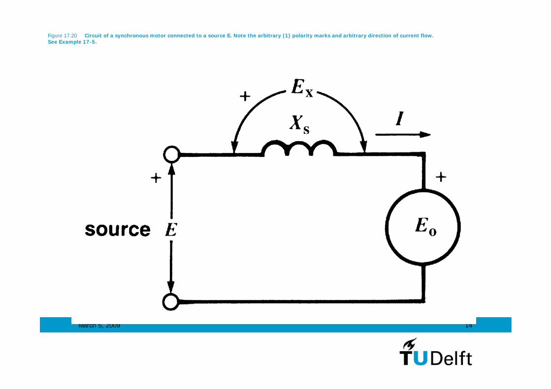
Figure 17.20 Circuit of a synchronous motor connected to a source E. Note the arbitrary (1) polarity marks and arbitrary direction of current flow. See Example 17-5.

March 5, 2009 15
Figure 17.21 See Example 17-5.

March 5, 2009 16
Figure 17.22a Motor turning at 600 r/min (Example 17-6).

March 5, 2009 17
Figure 17.22b Motor turning at 150 r/min (Example 17-6).

March 5, 2009 18
Figure 17.23 Comparison between the efficiency (a) and starting torque (b) of a squirrel-cage induction motor and a synchronous motor, both rated at 4000 hp, 1800 r/min, 6.9 kV, 60 Hz.

March 5, 2009 19
Figure 17.23 (continued) Comparison between the efficiency (a) and starting torque (b) of a squirrel-cage induction motor and a synchronousmotor, both rated at 4000 hp, 1800 r/min, 6.9 kV, 60 Hz.

March 5, 2009 20
Figure 17.24a Three-phase, 16 kV, 900 r/min synchronous capacitor rated 2200 Mvar (supplying reactive power) to 1300 Mvar (absorbing reactive power). It is used to regulate the voltage of a 735 kV transmission line. Other characteristics: mass of rotor: 143 t; rotor diameter: 2670 mm; axial length of stator iron: 3200 mm; air gap length: 39.7 mm.
March 5, 2009 21
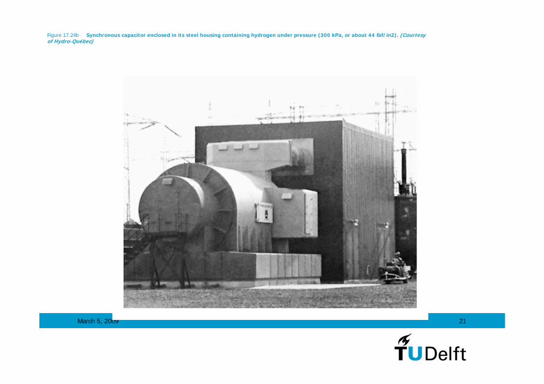
Figure 17.24b Synchronous capacitor enclosed in its steel housing containing hydrogen under pressure (300 kPa, or about 44 lbf/in2). (Courtesy of Hydro-Québec)

March 5, 2009 22
Figure 17.25a Under-excited synchronous capacitor absorbs reactive power (Example 17-7).

March 5, 2009 23
Figure 17.25b Over-excited synchronous capacitor delivers reactive power (Example 17-7).