ELECTRICAL & POWER CONTROL BCSB A -...
88
BCS BCS-1 ELECTRICAL & POWER CONTROL C D E F G H I J K L B SECTION BCS A O P N CONTENTS BODY CONTROL SYSTEM BCM BASIC INSPECTION ................................... 3 DIAGNOSIS AND REPAIR WORKFLOW ......... 3 Work Flow ................................................................ 3 FUNCTION DIAGNOSIS .............................. 6 BODY CONTROL SYSTEM ............................... 6 System Description .................................................. 6 Component Parts Location ....................................... 7 COMBINATION SWITCH READING SYSTEM ..... 8 System Diagram ....................................................... 8 System Description .................................................. 8 SIGNAL BUFFER SYSTEM ..............................12 System Diagram ..................................................... 12 System Description ................................................ 12 POWER CONSUMPTION CONTROL SYS- TEM ...................................................................13 System Diagram ..................................................... 13 System Description ................................................ 13 Component Parts Location ..................................... 15 DIAGNOSIS SYSTEM (BCM) ...........................16 COMMON ITEM ........................................................ 16 COMMON ITEM : Diagnosis Description ............... 16 COMMON ITEM : CONSULT-III Function .............. 16 DOOR LOCK ............................................................ 16 DOOR LOCK : CONSULT-III Function (BCM - DOOR LOCK) ........................................................ 17 REAR WINDOW DEFOGGER .................................. 17 REAR WINDOW DEFOGGER : CONSULT-III Function (BCM - REAR DEFOGGER) ................... 17 BUZZER .................................................................... 17 BUZZER : CONSULT-III Function ..........................17 INT LAMP ..................................................................18 INT LAMP : CONSULT-III Function ........................18 HEADLAMP ..............................................................20 HEADLAMP : CONSULT-III Function .....................20 WIPER .......................................................................22 WIPER : CONSULT - III Function ...........................22 FLASHER ..................................................................23 FLASHER : CONSULT-III Function ........................23 AIR CONDITIONER ..................................................23 AIR CONDITIONER : CONSULT-III Function (BCM - AUTO AIR CONDITIONER) .......................23 INTELLIGENT KEY ...................................................24 INTELLIGENT KEY : CONSULT-III Function (BCM - INTELLIGENT KEY) ...................................24 COMB SW .................................................................24 COMB SW : CONSULT-III Function .......................24 BCM ..........................................................................25 BCM : CONSULT-III Function (BCM - BCM) ..........25 IMMU .........................................................................25 IMMU : CONSULT-III Function (BCM - IMMU) .......25 BATTERY SAVER ....................................................25 BATTERY SAVER : CONSULT-III Function ...........25 TRUNK ......................................................................26 TRUNK : CONSULT-III Function (BCM - TRUNK) ....26 THEFT ALM ..............................................................27 THEFT ALM : CONSULT-III Function (BCM - THEFT ALM) ..........................................................27 RETAINED PWR .......................................................27 RETAINED PWR : CONSULT-III Function (BCM - RETAINED PWR) ...................................................27
Transcript of ELECTRICAL & POWER CONTROL BCSB A -...

ELECTRICAL & POWER CONTROL
C
D
E
BSECTION BCS
A
BODY CONTROL SYSTEM
CS
F
G
H
I
J
K
L
O
P
N
CONTENTS
B
BCM
BASIC INSPECTION .................................... 3
DIAGNOSIS AND REPAIR WORKFLOW .......... 3Work Flow .................................................................3
FUNCTION DIAGNOSIS ............................... 6
BODY CONTROL SYSTEM ................................ 6System Description ...................................................6Component Parts Location ........................................7
COMBINATION SWITCH READING SYSTEM ..... 8
System Diagram ........................................................8System Description ...................................................8
SIGNAL BUFFER SYSTEM ...............................12System Diagram ......................................................12System Description .................................................12
POWER CONSUMPTION CONTROL SYS-TEM ....................................................................13
System Diagram ......................................................13System Description .................................................13Component Parts Location ......................................15
DIAGNOSIS SYSTEM (BCM) ............................16
COMMON ITEM .........................................................16COMMON ITEM : Diagnosis Description ................16COMMON ITEM : CONSULT-III Function ...............16
DOOR LOCK .............................................................16DOOR LOCK : CONSULT-III Function (BCM - DOOR LOCK) .........................................................17
REAR WINDOW DEFOGGER ...................................17REAR WINDOW DEFOGGER : CONSULT-III Function (BCM - REAR DEFOGGER) ....................17
BUZZER .....................................................................17
BUZZER : CONSULT-III Function ...........................17
INT LAMP ...................................................................18INT LAMP : CONSULT-III Function .........................18
HEADLAMP ...............................................................20HEADLAMP : CONSULT-III Function ......................20
WIPER ........................................................................22WIPER : CONSULT - III Function ............................22
FLASHER ...................................................................23FLASHER : CONSULT-III Function .........................23
AIR CONDITIONER ...................................................23AIR CONDITIONER : CONSULT-III Function (BCM - AUTO AIR CONDITIONER) ........................23
INTELLIGENT KEY ....................................................24INTELLIGENT KEY : CONSULT-III Function (BCM - INTELLIGENT KEY) ....................................24
COMB SW ..................................................................24COMB SW : CONSULT-III Function ........................24
BCM ...........................................................................25BCM : CONSULT-III Function (BCM - BCM) ...........25
IMMU ..........................................................................25IMMU : CONSULT-III Function (BCM - IMMU) ........25
BATTERY SAVER .....................................................25BATTERY SAVER : CONSULT-III Function ............25
TRUNK .......................................................................26TRUNK : CONSULT-III Function (BCM - TRUNK) ....26
THEFT ALM ...............................................................27THEFT ALM : CONSULT-III Function (BCM - THEFT ALM) ...........................................................27
RETAINED PWR ........................................................27RETAINED PWR : CONSULT-III Function (BCM - RETAINED PWR) ....................................................27
BCS-1
SIGNAL BUFFER ...................................................... 27SIGNAL BUFFER : CONSULT-III Function ............ 27
AIR PRESSURE MONITOR ...................................... 27AIR PRESSURE MONITOR : Diagnosis Descrip-tion .......................................................................... 27AIR PRESSURE MONITOR : CONSULT-III Func-tion .......................................................................... 29
FUSE, FUSIBLE LINK .............................................. 30FUSE, FUSIBLE LINK : CONSULT-III Function ..... 30
COMPONENT DIAGNOSIS ........................ 31
U1000 CAN COMM CIRCUIT ............................ 31Description .............................................................. 31DTC Logic ............................................................... 31Diagnosis Procedure .............................................. 31
U1010 CONTROL UNIT (CAN) ......................... 32DTC Logic ............................................................... 32Diagnosis Procedure .............................................. 32
U0415 VEHICLE SPEED SIG ............................ 33Description .............................................................. 33DTC Logic ............................................................... 33Diagnosis Procedure .............................................. 33
B2562 LOW VOLTAGE ..................................... 34DTC Logic ............................................................... 34Diagnosis Procedure .............................................. 34Special Repair Requirement ................................... 34
B2563 HI VOLTAGE .......................................... 35DTC Logic ............................................................... 35Diagnosis Procedure .............................................. 35Special Repair Requirement ................................... 35
POWER SUPPLY AND GROUND CIRCUIT ..... 36Diagnosis Procedure ............................................... 36Special Repair Requirement ................................... 36
COMBINATION SWITCH INPUT CIRCUIT ....... 37Diagnosis Procedure ............................................... 37Special Repair Requirement ................................... 38
COMBINATION SWITCH OUTPUT CIRCUIT ... 39Diagnosis Procedure ............................................... 39Special Repair Requirement ................................... 40
ECU DIAGNOSIS ....................................... 41
BCM (BODY CONTROL MODULE) .................. 41Reference Value ..................................................... 41Terminal Layout ...................................................... 45Physical Values ....................................................... 45Wiring Diagram-Coupe ........................................... 64Wiring Diagram-Sedan ............................................ 73Fail Safe ................................................................. 81DTC Inspection Priority Chart ............................... 83DTC Index .............................................................. 85
SYMPTOM DIAGNOSIS ............................ 87
COMBINATION SWITCH SYSTEM SYMP-TOMS ................................................................. 87
Symptom Table ....................................................... 87
ON-VEHICLE REPAIR ............................... 88
BCM (BODY CONTROL MODULE) .................. 88Removal and Installation ......................................... 88
BCS-2
CS
DIAGNOSIS AND REPAIR WORKFLOW[BCM]
C
D
E
F
G
H
I
J
K
L
B
A
O
P
N
B
< BASIC INSPECTION >
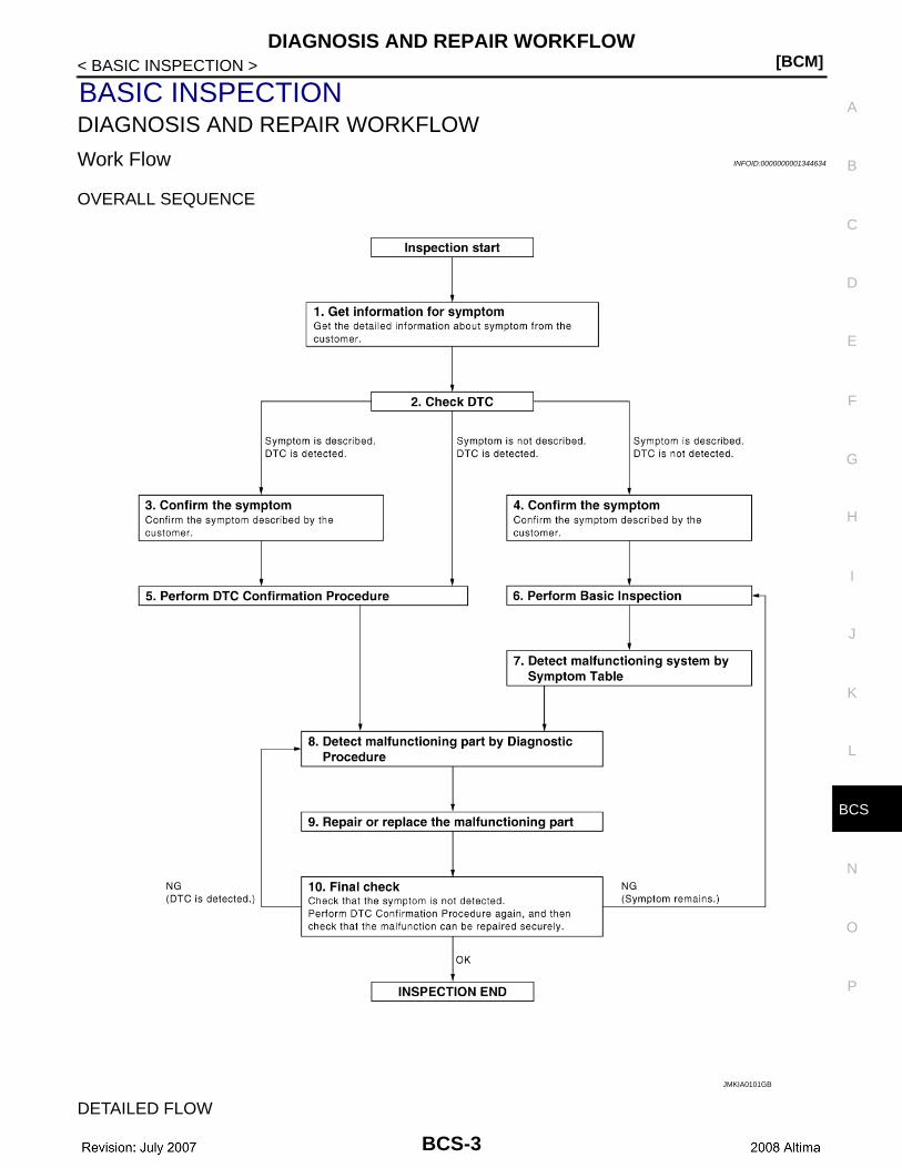
BASIC INSPECTIONDIAGNOSIS AND REPAIR WORKFLOW
Work Flow INFOID:0000000001344634
OVERALL SEQUENCE
DETAILED FLOW
JMKIA0101GB
BCS-3

[BCM]DIAGNOSIS AND REPAIR WORKFLOW
< BASIC INSPECTION >
1. GET INFORMATION FOR SYMPTOM
Get the detailed information from the customer about the symptom (the condition and the environment whenthe incident/malfunction occurred).
>> GO TO 2
2. CHECK DTC
1. Check DTC.2. Perform the following procedure if DTC is displayed.- Record DTC and freeze frame data.- Erase DTC.- Study the relationship between the cause detected by DTC and the symptom described by the customer.3. Check related service bulletins for information.Is any symptom described and any DTC detected?Symptom is described, DTC is displayed>>GO TO 3Symptom is described, DTC is not displayed>>GO TO 4Symptom is not described, DTC is displayed>>GO TO 5
3. CONFIRM THE SYMPTOM
Confirm the symptom described by the customer.Connect CONSULT-III to the vehicle in “DATA MONITOR” mode and check real time diagnosis results.Verify relation between the symptom and the condition when the symptom is detected.
>> GO TO 5
4. CONFIRM THE SYMPTOM
Confirm the symptom described by the customer.Connect CONSULT-III to the vehicle in “DATA MONITOR ” mode and check real time diagnosis results.Verify relation between the symptom and the condition when the symptom is detected.
>> GO TO 6
5. PERFORM DTC CONFIRMATION PROCEDURE
Perform DTC Confirmation Procedure for the displayed DTC, and then check that DTC is detected again.At this time, always connect CONSULT-III to the vehicle, and check diagnostic results in real time.If two or more DTCs are detected, refer to BCS-83, "DTC Inspection Priority Chart" and determine troublediagnosis order.NOTE:• Freeze frame data is useful if the DTC is not detected.• Perform Component Function Check if DTC Confirmation Procedure is not included in Service Manual. This
simplified check procedure is an effective alternative though DTC cannot be detected during this check.If the result of Component Function Check is NG, it is the same as the detection of DTC by DTC Confirma-tion Procedure.
Is DTC detected?YES >> GO TO 8NO >> Refer to BCS-85, "DTC Index".
6. PERFORM BASIC INSPECTION
Perform BCS-3, "Work Flow".
Inspection End>>GO TO 7
7. DETECT MALFUNCTIONING SYSTEM BY SYMPTOM TABLE
Detect malfunctioning system according to BCS-6, "System Description" based on the confirmed symptom instep 4, and determine the trouble diagnosis order based on possible causes and symptom.
>> GO TO 8
BCS-4
CS
DIAGNOSIS AND REPAIR WORKFLOW[BCM]
C
D
E
F
G
H
I
J
K
L
B
A
O
P
N
B
< BASIC INSPECTION >
8. DETECT MALFUNCTIONING PART BY DIAGNOSTIC PROCEDURE
Inspect according to Diagnostic Procedure of the system.NOTE:The Diagnostic Procedure described based on open circuit inspection. A short circuit inspection is alsorequired for the circuit check in the Diagnostic Procedure.Is malfunctioning part detected?YES >> GO TO 9NO >> Check voltage of related BCM terminals using CONSULT-III.
9. REPAIR OR REPLACE THE MALFUNCTIONING PART
1. Repair or replace the malfunctioning part.2. Reconnect parts or connectors disconnected during Diagnostic Procedure again after repair and replace-
ment.3. Check DTC. If DTC is displayed, erase it.
>> GO TO 10
10. FINAL CHECK
When DTC was detected in step 2, perform DTC Confirmation Procedure or Component Function Checkagain, and then check that the malfunction have been repaired securely.When symptom was described from the customer, refer to confirmed symptom in step 3 or 4, and check thatthe symptom is not detected.Does the symptom reappear?YES (DTC is detected)>>GO TO 8YES (Symptom remains)>>GO TO 6NO >> Inspection End.
BCS-5
[BCM]BODY CONTROL SYSTEM
< FUNCTION DIAGNOSIS >
FUNCTION DIAGNOSISBODY CONTROL SYSTEM
System Description INFOID:0000000001344635
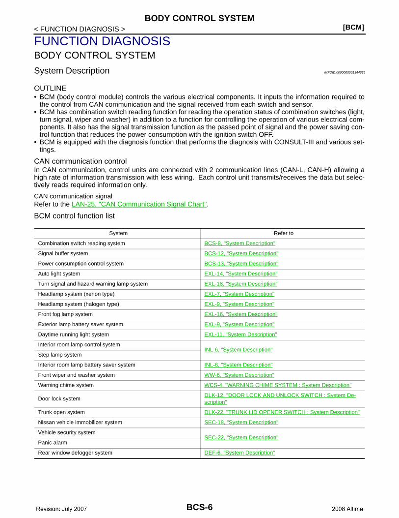
OUTLINE• BCM (body control module) controls the various electrical components. It inputs the information required to
the control from CAN communication and the signal received from each switch and sensor. • BCM has combination switch reading function for reading the operation status of combination switches (light,
turn signal, wiper and washer) in addition to a function for controlling the operation of various electrical com-ponents. It also has the signal transmission function as the passed point of signal and the power saving con-trol function that reduces the power consumption with the ignition switch OFF.
• BCM is equipped with the diagnosis function that performs the diagnosis with CONSULT-III and various set-tings.
CAN communication controlIn CAN communication, control units are connected with 2 communication lines (CAN-L, CAN-H) allowing ahigh rate of information transmission with less wiring. Each control unit transmits/receives the data but selec-tively reads required information only.
CAN communication signalRefer to the LAN-25, "CAN Communication Signal Chart".
BCM control function list
System Refer to
Combination switch reading system BCS-8, "System Description"
Signal buffer system BCS-12, "System Description"
Power consumption control system BCS-13, "System Description"
Auto light system EXL-14, "System Description"
Turn signal and hazard warning lamp system EXL-18, "System Description"
Headlamp system (xenon type) EXL-7, "System Description"
Headlamp system (halogen type) EXL-9, "System Description"
Front fog lamp system EXL-16, "System Description"
Exterior lamp battery saver system EXL-9, "System Description"
Daytime running light system EXL-11, "System Description"
Interior room lamp control systemINL-6, "System Description"
Step lamp system
Interior room lamp battery saver system INL-6, "System Description"
Front wiper and washer system WW-6, "System Description"
Warning chime system WCS-4, "WARNING CHIME SYSTEM : System Description"
Door lock systemDLK-12, "DOOR LOCK AND UNLOCK SWITCH : System De-scription"
Trunk open system DLK-22, "TRUNK LID OPENER SWITCH : System Description"
Nissan vehicle immobilizer system SEC-18, "System Description"
Vehicle security systemSEC-22, "System Description"
Panic alarm
Rear window defogger system DEF-6, "System Description"
BCS-6
CS
BODY CONTROL SYSTEM[BCM]
C
D
E
F
G
H
I
J
K
L
B
A
O
P
N
B
< FUNCTION DIAGNOSIS >
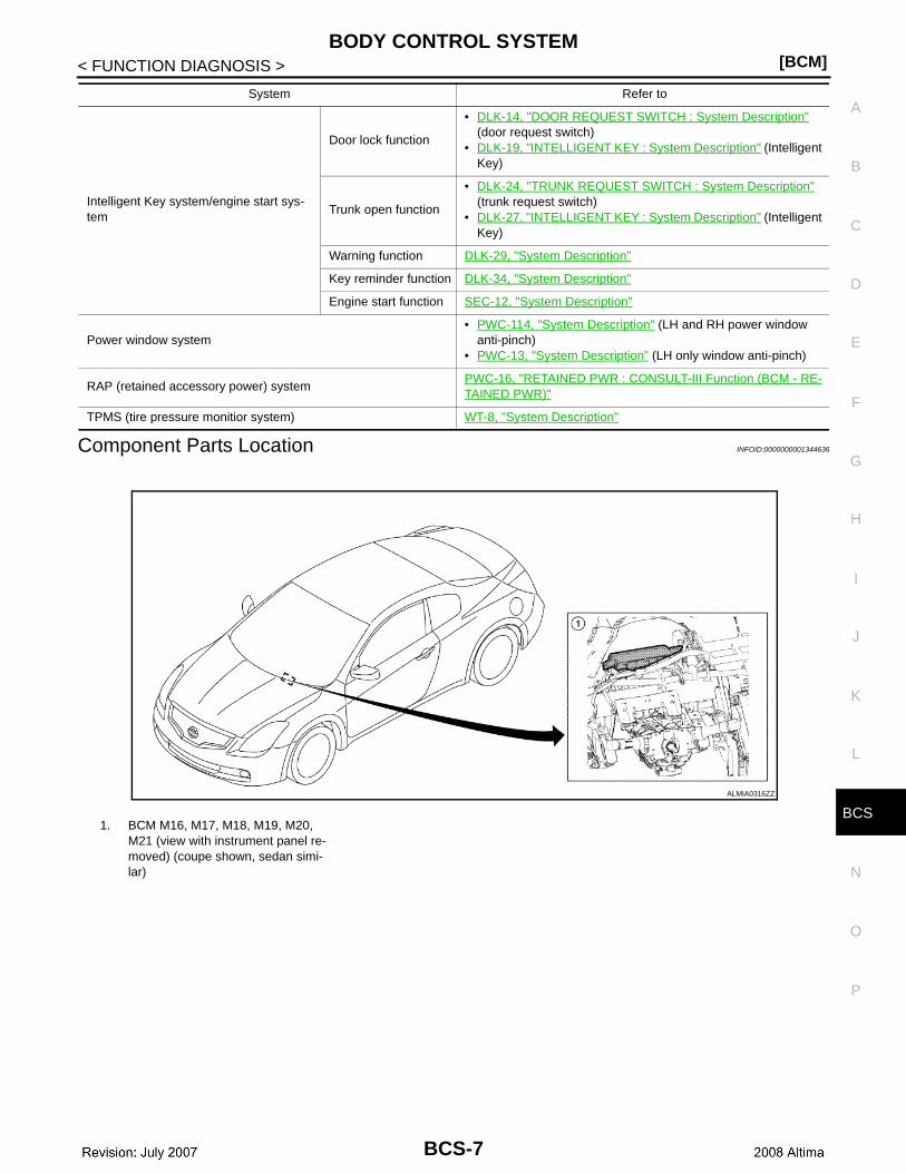
Component Parts Location INFOID:0000000001344636
Intelligent Key system/engine start sys-tem
Door lock function
• DLK-14, "DOOR REQUEST SWITCH : System Description" (door request switch)
• DLK-19, "INTELLIGENT KEY : System Description" (Intelligent Key)
Trunk open function
• DLK-24, "TRUNK REQUEST SWITCH : System Description" (trunk request switch)
• DLK-27, "INTELLIGENT KEY : System Description" (Intelligent Key)
Warning function DLK-29, "System Description"
Key reminder function DLK-34, "System Description"
Engine start function SEC-12, "System Description"
Power window system• PWC-114, "System Description" (LH and RH power window
anti-pinch)• PWC-13, "System Description" (LH only window anti-pinch)
RAP (retained accessory power) systemPWC-16, "RETAINED PWR : CONSULT-III Function (BCM - RE-TAINED PWR)"
TPMS (tire pressure monitior system) WT-8, "System Description"
System Refer to
1. BCM M16, M17, M18, M19, M20, M21 (view with instrument panel re-moved) (coupe shown, sedan simi-lar)
ALMIA0316ZZ
BCS-7
[BCM]COMBINATION SWITCH READING SYSTEM
< FUNCTION DIAGNOSIS >
COMBINATION SWITCH READING SYSTEM
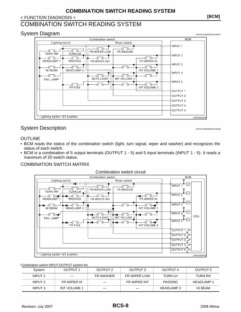
System Diagram INFOID:0000000001344637
System Description INFOID:0000000001344638
OUTLINE• BCM reads the status of the combination switch (light, turn signal, wiper and washer) and recognizes the
status of each switch.• BCM is a combination of 5 output terminals (OUTPUT 1 - 5) and 5 input terminals (INPUT 1 - 5). It reads a
maximum of 20 switch status.
COMBINATION SWITCH MATRIX
Combination switch circuit
Combination switch INPUT-OUTPUT system list
JPMIA0083GB
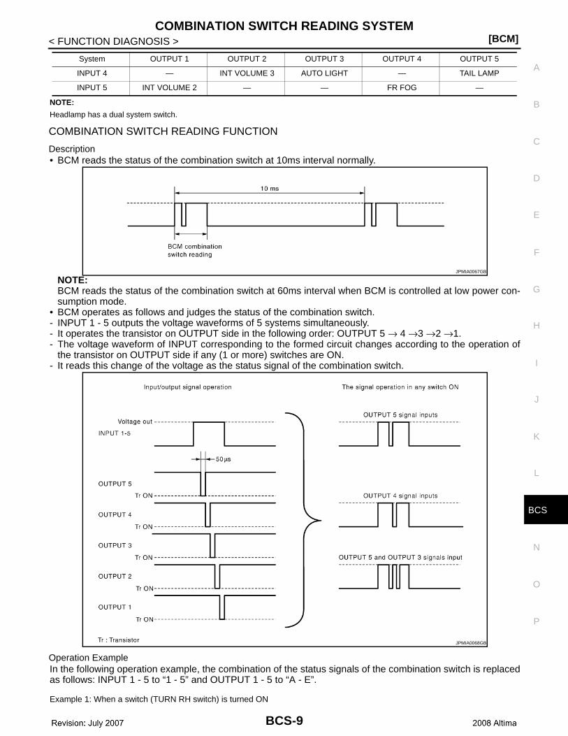
System OUTPUT 1 OUTPUT 2 OUTPUT 3 OUTPUT 4 OUTPUT 5
INPUT 1 — FR WASHER FR WIPER LOW TURN LH TURN RH
INPUT 2 FR WIPER HI — FR WIPER INT PASSING HEADLAMP 1
INPUT 3 INT VOLUME 1 — — HEADLAMP 2 HI BEAM
JPMIA0066GB
BCS-8
CS
COMBINATION SWITCH READING SYSTEM[BCM]
C
D
E
F
G
H
I
J
K
L
B
A
O
P
N
B
< FUNCTION DIAGNOSIS >
NOTE:
Headlamp has a dual system switch.
COMBINATION SWITCH READING FUNCTION
Description• BCM reads the status of the combination switch at 10ms interval normally.
NOTE:BCM reads the status of the combination switch at 60ms interval when BCM is controlled at low power con-sumption mode.
• BCM operates as follows and judges the status of the combination switch.- INPUT 1 - 5 outputs the voltage waveforms of 5 systems simultaneously.- It operates the transistor on OUTPUT side in the following order: OUTPUT 5 → 4 →3 →2 →1.- The voltage waveform of INPUT corresponding to the formed circuit changes according to the operation of
the transistor on OUTPUT side if any (1 or more) switches are ON.- It reads this change of the voltage as the status signal of the combination switch.
Operation ExampleIn the following operation example, the combination of the status signals of the combination switch is replacedas follows: INPUT 1 - 5 to “1 - 5” and OUTPUT 1 - 5 to “A - E”.
Example 1: When a switch (TURN RH switch) is turned ON
INPUT 4 — INT VOLUME 3 AUTO LIGHT — TAIL LAMP
INPUT 5 INT VOLUME 2 — — FR FOG —
System OUTPUT 1 OUTPUT 2 OUTPUT 3 OUTPUT 4 OUTPUT 5
JPMIA0067GB
JPMIA0068GB
BCS-9
[BCM]COMBINATION SWITCH READING SYSTEM
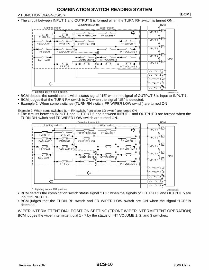
< FUNCTION DIAGNOSIS >• The circuit between INPUT 1 and OUTPUT 5 is formed when the TURN RH switch is turned ON.
• BCM detects the combination switch status signal “1E” when the signal of OUTPUT 5 is input to INPUT 1.• BCM judges that the TURN RH switch is ON when the signal “1E” is detected.• Example 2: When some switches (TURN RH switch, FR WIPER LOW switch) are turned ON
Example 2: When some switches (turn RH switch, front wiper LO switch) are turned ON• The circuits between INPUT 1 and OUTPUT 5 and between INPUT 1 and OUTPUT 3 are formed when the
TURN RH switch and FR WIPER LOW switch are turned ON.
• BCM detects the combination switch status signal “1CE” when the signals of OUTPUT 3 and OUTPUT 5 areinput to INPUT 1.
• BCM judges that the TURN RH switch and FR WIPER LOW switch are ON when the signal “1CE” isdetected.
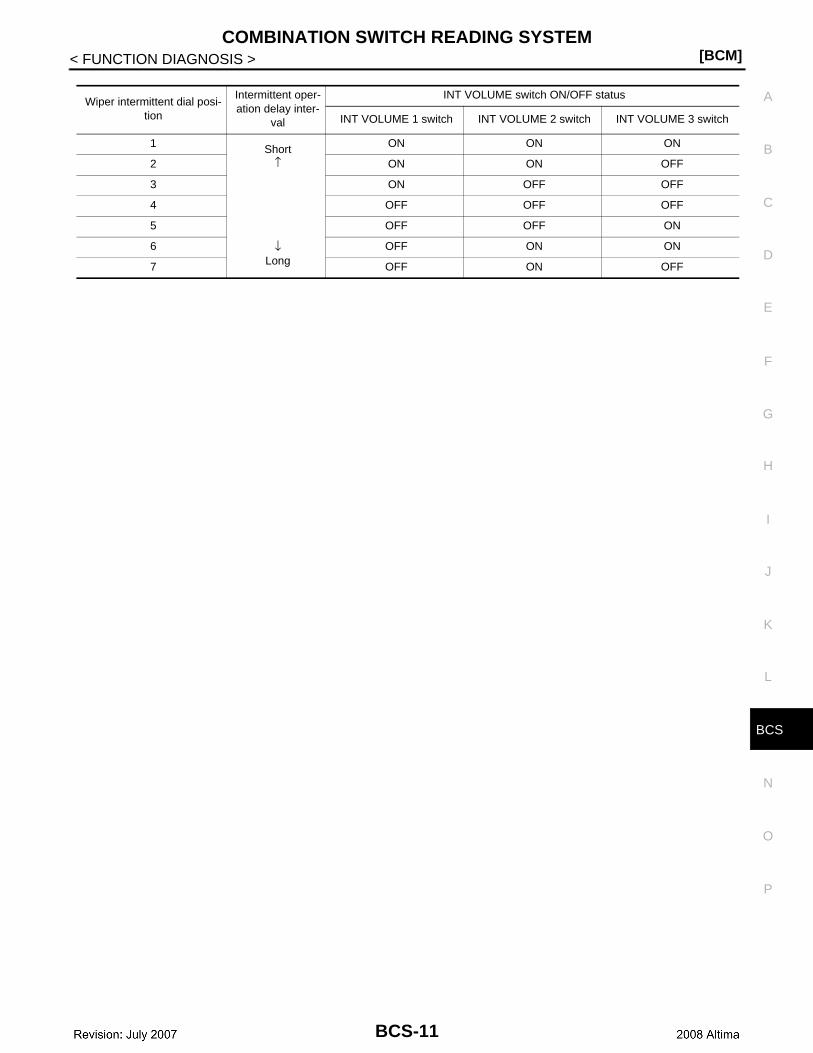
WIPER INTERMITTENT DIAL POSITION SETTING (FRONT WIPER INTERMITTENT OPERATION)BCM judges the wiper intermittent dial 1 - 7 by the status of INT VOLUME 1, 2, and 3 switches.
JPMIA0073GB
JPMIA0074GB
BCS-10
CS
COMBINATION SWITCH READING SYSTEM[BCM]
C
D
E
F
G
H
I
J
K
L
B
A
O
P
N
B
< FUNCTION DIAGNOSIS >
Wiper intermittent dial posi-tion
Intermittent oper-ation delay inter-
val
INT VOLUME switch ON/OFF status
INT VOLUME 1 switch INT VOLUME 2 switch INT VOLUME 3 switch
1 Short↑
↓Long
ON ON ON
2 ON ON OFF
3 ON OFF OFF
4 OFF OFF OFF
5 OFF OFF ON
6 OFF ON ON
7 OFF ON OFF
BCS-11

[BCM]SIGNAL BUFFER SYSTEM
< FUNCTION DIAGNOSIS >
SIGNAL BUFFER SYSTEM
System Diagram INFOID:0000000001344639
System Description INFOID:0000000001344640
OUTLINEBCM has the signal transmission function that outputs/transmits each input/received signal to each unit.
Signal transmission function list
JPMIA0070GB
Signal name Input Output Description
• Ignition switch ON signal• Ignition switch signal
Engine switch (push switch) IPDM E/R (CAN)
Inputs the push-button ignition switch (push switch) signal and transmits the ignition switch sta-tus judged with BCM via CAN communication.
Door switch signal Any door switch• Combination meter (CAN)• IPDM E/R (CAN)
Inputs the door switch signal and transmits it via CAN com-munication.
Trunk switch signal Trunk room lamp switch Combination meter (CAN)
Inputs the trunk room lamp switch signal and transmits the trunk switch signal via CAN communication.
Oil pressure switch signal IPDM E/R (CAN) Combination meter (CAN)Transmits the received oil pres-sure switch signal via CAN communication.
BCS-12

CS
POWER CONSUMPTION CONTROL SYSTEM[BCM]
C
D
E
F
G
H
I
J
K
L
B
A
O
P
N
B
< FUNCTION DIAGNOSIS >
POWER CONSUMPTION CONTROL SYSTEM
System Diagram INFOID:0000000001344641
System Description INFOID:0000000001344642
OUTLINE• BCM incorporates a power saving control function that reduces the power consumption according to the
vehicle status. • BCM switches the status (control mode) by itself with the power saving control function. It performs the sleep
request to each unit (IPDM E/R and combination meter) that operates with the ignition switch OFF.
Normal mode (wake-up)- CAN communication is normally performed with other units- Each control with BCM is operating properly
CAN communication sleep mode (CAN sleep)- CAN transmission is stopped- Control with BCM only is operating
Low power consumption mode (BCM sleep)- Low power consumption control is active- CAN transmission is stopped
LOW POWER CONSUMPTION CONTROL WITH BCMBCM reduces the power consumption with the following operation in the low power consumption mode.• The reading interval of the each switches changes from 10 ms interval to 60 ms interval.
Sleep mode activation• BCM receives the sleep-ready signal (ready) from IPDM E/R and combination meter via CAN communica-
tion.• BCM transmits the sleep wake up signal (sleep) to each unit when all of the CAN sleep conditions are ful-
filled.• Each unit stops the transmission of CAN communication with the sleep wakeup signal. BCM is in CAN com-
munication sleep mode.• BCM is in the low power consumption mode and perform the low power consumption control when all of the
BCM sleep conditions are fulfilled with CAN sleep condition.
ALCIA0030GB
BCS-13

[BCM]POWER CONSUMPTION CONTROL SYSTEM
< FUNCTION DIAGNOSIS >Sleep condition
Wake-up operation• BCM changes from the low power consumption mode to the CAN communication sleep mode when the any
of the BCM wake-up conditions is fulfilled. Only the control with BCM is activated.• BCM transmits the sleep wake up signal (wake up) to each unit when any of the CAN wake-up conditions is
fulfilled. It changes from the low power consumption mode or the CAN communication sleep mode to thenormal mode.
• Each unit starts the transmission of CAN communication with the sleep wake up signal. In addition, the com-bination meter transmits the wake up signal to BCM via CAN communication to report the CAN communica-tion start.
Wake-up condition
CAN sleep condition BCM sleep condition
• Receiving the sleep-ready signal (ready) from all units• Ignition switch: OFF• Vehicle security system alarm and panic alarm : No operation• Warning lamp: Not operation• Intelligent Key system buzzer: No operation• Trunk room lamp switch status: No change• Brake switch: OFF• Key slot status: No change• Turn signal indicator lamp: No operation• Exterior lamp: OFF• Door lock status: No change• CONSULT-III communication status: No communication• Meter display signal : Non-transmission• Electronic steering column lock operation: No operation• Door switch status: No change• Rear window defogger: OFF
• Interior room lamp battery saver: Time out• RAP system: OFF• Power window switch communication: No transmission• Push-button ignition switch (push switch) illumination: OFF• NATS: No operation• Remote keyless entry receiver communication status: No
communication• Tire pressure monitor system: Stop
BCM wake-up condition CAN wake-up condition
• Door unlock sensor: OFF→ON, ON→OFF• Door lock lock assembly LH (key cylinder switch): Lock or un-
lock• Door lock switch: OFF→ON• Door unlock switch: OFF→ON• Trunk lid opener switch: OFF→ON• Power window serial link communication: Receiving• Remote keyless entry receiver: Receiving valid keyfob
• Receiving the sleep-ready signal (Not-ready) from any units• Key slot: OFF→ON, ON→OFF• Push-button ignition switch (push switch): OFF→ON• Hazard switch: OFF→ON• PASSING switch: OFF→ON, ON→OFF• TAIL LAMP switch: OFF→ON• Driver door switch: OFF→ON, ON→OFF• Passenger door switch: OFF → ON, ON → OFF• Trunk room lamp switch: OFF→ON, ON→OFF• Driver door request switch: OFF→ON• Passenger door request switch: OFF→ON• Trunk request switch: OFF→ON• Stop lamp switch 2 signal: ON• Clutch interlock switch: OFF→ON• Remote keyless entry receiver: Receiving valid keyfob
BCS-14

CS
POWER CONSUMPTION CONTROL SYSTEM[BCM]
C
D
E
F
G
H
I
J
K
L
B
A
O
P
N
B
< FUNCTION DIAGNOSIS >
Component Parts Location INFOID:0000000001344643
1. BCM M16, M17, M18, M19, M20, M21 (view with instrument panel re-moved) (coupe shown, sedan simi-lar)
2. Combination meter M24 3. IPDM E/R E16, E17, E18, E200, E201, F10
ALMIA0317ZZ
BCS-15

[BCM]DIAGNOSIS SYSTEM (BCM)
< FUNCTION DIAGNOSIS >
DIAGNOSIS SYSTEM (BCM)COMMON ITEM
COMMON ITEM : Diagnosis Description INFOID:0000000001344644
BCM CONSULT-III FUNCTIONCONSULT-III performs the following functions via CAN communication with BCM.
SYSTEM APPLICATIONBCM can perform the following functions for each system.NOTE:It can perform the diagnosis modes except the following for all sub system selection items.
COMMON ITEM : CONSULT-III Function INFOID:0000000001344645
ECU IDENTIFICATIONDisplays the BCM part No.
SELF-DIAG RESULTRefer to BCS-85, "DTC Index".DOOR LOCK
Diagnosis mode Function Description
WORK SUPPORT Changes the setting for each system function.
SELF-DIAG RESULTS Displays the diagnosis results judged by BCM.
CAN DIAG SUPPORT MNTR Monitors the reception status of CAN communication viewed from BCM.
DATA MONITOR The BCM input/output signals are displayed.
ACTIVE TEST The signals used to activate each device are forcibly supplied from BCM.
ECU IDENTIFICATION The BCM part number is displayed.
CONFIGURATION This function is not used even though it is displayed.
System Sub system selection itemDiagnosis mode
WORK SUPPORT DATA MONITOR ACTIVE TEST
Door lock DOOR LOCK × × ×
Rear window defogger REAR DEFOGGER × ×
Warning chime BUZZER × ×
Interior room lamp timer INT LAMP × × ×
Exterior lamp HEADLAMP × × ×
Wiper and washer WIPER × × ×
Turn signal and hazard warning lamps FLASHER × × ×
Air conditioner AIR CONDITONER ×
Intelligent Key system INTELLIGENT KEY × × ×
Combination switch COMB SW ×
BCM BCM ×
Immobilizer IMMU × ×
Interior room lamp battery saver BATTERY SAVER × × ×
Trunk open TRUNK ×
Vehicle security system THEFT ALM × × ×
RAP system RETAINED PWR ×
Signal buffer system SIGNAL BUFFER × ×
TPMS AIR PRESSURE MONITOR × ×
BCS-16

CS
DIAGNOSIS SYSTEM (BCM)[BCM]
C
D
E
F
G
H
I
J
K
L
B
A
O
P
N
B
< FUNCTION DIAGNOSIS >
DOOR LOCK : CONSULT-III Function (BCM - DOOR LOCK) INFOID:0000000003183616
WORK SUPPORT
DATA MONITOR
ACTIVE TEST
REAR WINDOW DEFOGGER
REAR WINDOW DEFOGGER : CONSULT-III Function (BCM - REAR DEFOGGER)INFOID:0000000003183617
DATA MONITOR
BUZZER
BUZZER : CONSULT-III Function INFOID:0000000001344646
CONSULT-III APPLICATION ITEMS
Work Item Description
DOOR LOCK-UNLOCK SET• ON• OFF
ANTI-LOCK OUT SET • ON• OFF
Monitor Item[Unit}
Description
IGN ON SW [ON/OFF] Indicates condition of ignition switch in ON position
KEY ON SW [ON/OFF] Indicates condition of key switch
CDL LOCK SW [ON/OFF] Indicates condition of door lock and unlock switch
CDL UNLOCK SW [ON/OFF] Indicates condition of door lock and unlock switch
DOOR SW-DR [ON/OFF] Indicates condition of front door switch LH
DOOR SW-AS [ON/OFF] Indicates condition of front door switch RH
DOOR SW-RR [ON/OFF] Indicates condition of rear door switch RH
DOOR SW-RL [ON/OFF] Indicates condition of rear door switch LH
BACK DOOR SW [ON/OFF] Indicates condition of back door switch
KEY CYL LK-SW [ON/OFF] Indicates condition of lock signal from door key cylinder switch
KEY CYL UN-SW [ON/OFF] Indicates condition of unlock signal from door key cylinder switch
I-KEY LOCK [ON/OFF] Indicates condition of lock signal from Intelligent Key
I-KEY UNLOCK [ON/OFF] Indicates condition of unlock signal from Intelligent Key
Test Item Description
DOOR LOCKThis test is able to check door lock operation [ALL LOCK/ALL UNLOCK/DR UNLOCK/OTHER UNLOCK].
TRUNK/BACK DOOR This test is able to check trunk/back door lock operation [LOCK (SET)/UNLOCK (RE-LEASE)].
Monitor Item[Unit]
Description
IGN ON SW [ON/OFF] Indicates condition of ignition switch in ON position
IGN ACC SW [ON/OFF] Indicates condition of ignition switch in ACC position
REAR DEF SW [ON/OFF] Displays “Press (ON)/other (OFF)” status determined with the rear window defogger switch
BCS-17
[BCM]DIAGNOSIS SYSTEM (BCM)
< FUNCTION DIAGNOSIS >
DATA MONITOR
ACTIVE TEST
INT LAMP
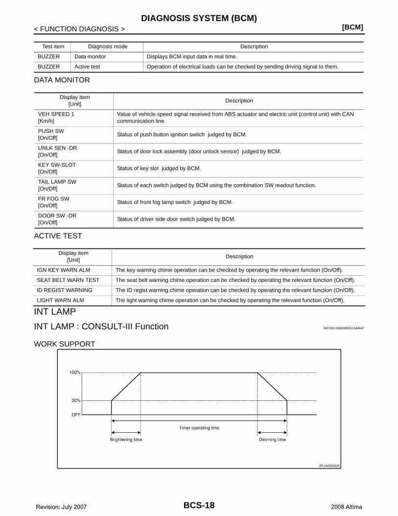
INT LAMP : CONSULT-III Function INFOID:0000000001344647
WORK SUPPORT
Test item Diagnosis mode Description
BUZZER Data monitor Displays BCM input data in real time.
BUZZER Active test Operation of electrical loads can be checked by sending driving signal to them.
Display item[Unit]
Description
VEH SPEED 1[Km/h]
Value of vehicle speed signal received from ABS actuator and electric unit (control unit) with CAN communication line.
PUSH SW[On/Off]
Status of push button ignition switch judged by BCM.
UNLK SEN -DR[On/Off]
Status of door lock assembly (door unlock sensor) judged by BCM.
KEY SW-SLOT[On/Off]
Status of key slot judged by BCM.
TAIL LAMP SW[On/Off]
Status of each switch judged by BCM using the combination SW readout function.
FR FOG SW[On/Off]
Status of front fog lamp switch judged by BCM.
DOOR SW -DR[On/Off]
Status of driver side door switch judged by BCM.
Display item[Unit]
Description
IGN KEY WARN ALM The key warning chime operation can be checked by operating the relevant function (On/Off).
SEAT BELT WARN TEST The seat belt warning chime operation can be checked by operating the relevant function (On/Off).
ID REGIST WARNING The ID regist warning chime operation can be checked by operating the relevant function (On/Off).
LIGHT WARN ALM The light warning chime operation can be checked by operating the relevant function (On/Off).
JPLIA0093GB
BCS-18
CS
DIAGNOSIS SYSTEM (BCM)[BCM]
C
D
E
F
G
H
I
J
K
L
B
A
O
P
N
B
< FUNCTION DIAGNOSIS >
* : Initial setting
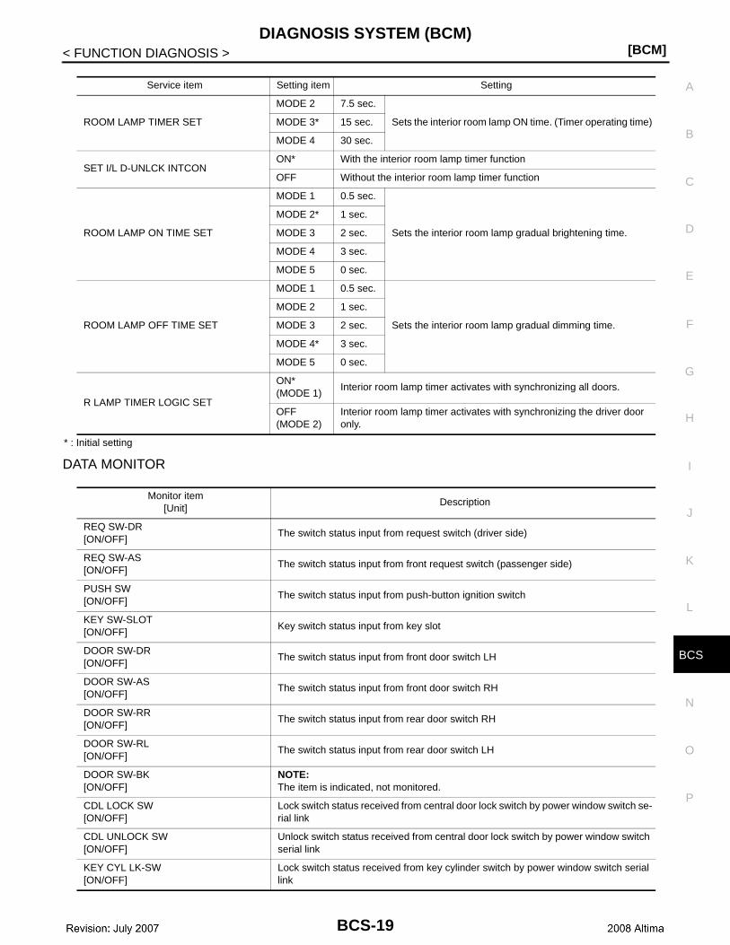
DATA MONITOR
Service item Setting item Setting
ROOM LAMP TIMER SET
MODE 2 7.5 sec.
Sets the interior room lamp ON time. (Timer operating time)MODE 3* 15 sec.
MODE 4 30 sec.
SET I/L D-UNLCK INTCONON* With the interior room lamp timer function
OFF Without the interior room lamp timer function
ROOM LAMP ON TIME SET
MODE 1 0.5 sec.
Sets the interior room lamp gradual brightening time.
MODE 2* 1 sec.
MODE 3 2 sec.
MODE 4 3 sec.
MODE 5 0 sec.
ROOM LAMP OFF TIME SET
MODE 1 0.5 sec.
Sets the interior room lamp gradual dimming time.
MODE 2 1 sec.
MODE 3 2 sec.
MODE 4* 3 sec.
MODE 5 0 sec.
R LAMP TIMER LOGIC SET
ON* (MODE 1)
Interior room lamp timer activates with synchronizing all doors.
OFF (MODE 2)
Interior room lamp timer activates with synchronizing the driver door only.
Monitor item[Unit]
Description
REQ SW-DR[ON/OFF]
The switch status input from request switch (driver side)
REQ SW-AS[ON/OFF]
The switch status input from front request switch (passenger side)
PUSH SW[ON/OFF]
The switch status input from push-button ignition switch
KEY SW-SLOT[ON/OFF]
Key switch status input from key slot
DOOR SW-DR[ON/OFF]
The switch status input from front door switch LH
DOOR SW-AS[ON/OFF]
The switch status input from front door switch RH
DOOR SW-RR[ON/OFF]
The switch status input from rear door switch RH
DOOR SW-RL[ON/OFF]
The switch status input from rear door switch LH
DOOR SW-BK[ON/OFF]
NOTE:The item is indicated, not monitored.
CDL LOCK SW[ON/OFF]
Lock switch status received from central door lock switch by power window switch se-rial link
CDL UNLOCK SW[ON/OFF]
Unlock switch status received from central door lock switch by power window switch serial link
KEY CYL LK-SW[ON/OFF]
Lock switch status received from key cylinder switch by power window switch serial link
BCS-19

[BCM]DIAGNOSIS SYSTEM (BCM)
< FUNCTION DIAGNOSIS >
ACTIVE TEST
HEADLAMP
HEADLAMP : CONSULT-III Function INFOID:0000000001344648
WORK SUPPORT
1 : Initial setting
2: With auto light system
DATA MONITOR
KEY CYL UN-SW[ON/OFF]
Unlock switch status received from key cylinder switch by power window switch serial link
TRNK/HAT MNTR[ON/OFF]
The switch status input from trunk room lamp switch
RKE-LOCK[ON/OFF]
Lock signal status received from remote keyless entry receiver
RKE-UNLOCK[ON/OFF]
Unlock signal status received from remote keyless entry receiver
Monitor item[Unit]
Description
Test item Operation Description
INT LAMPON
Outputs the interior room lamp control signal to turn map lamp and personal lamp ON (Map lamp switch is in DOOR position).
OFF Stops the interior room lamp control signal to turn map lamp and personal lamp OFF.
STEP LAMP TESTON Outputs the step lamp control signal to turn step lamp ON.
OFF Stops the step lamp control signal to turn step lamp OFF.
LUGGAGE LAMP TESTON Outputs the luggage room lamp control signal to turn step lamp ON.
OFF Stops the luggage room lamp control signal to turn step lamp ON.
Service item Setting item Setting
BATTERY SAVER SETON1 With the exterior lamp battery saver function
OFF Without the exterior lamp battery saver function
ILL DELAY SET2
MODE 11 45 sec.
Sets delay timer function timer operation time(All doors closed)
MODE 2Without the func-tion
MODE 3 30 sec.
MODE 4 60 sec.
MODE 5 90 sec.
MODE 6 120 sec.
MODE 7 150 sec.
MODE 8 180 sec.
CUSTOM A/LIGHT
SETTING2
MODE 11 Normal
MODE 2 More sensitive setting than normal setting (Turns ON earlier than normal operation.)
MODE 3 More sensitive setting than MODE 2 (Turns ON earlier than MODE 2.)
MODE 4 Less sensitive setting than normal setting (Turns ON later than normal operation.)
BCS-20

CS
DIAGNOSIS SYSTEM (BCM)[BCM]
C
D
E
F
G
H
I
J
K
L
B
A
O
P
N
B
< FUNCTION DIAGNOSIS >
1: With auto light system.
2: The item is indicated, not monitored.
ACTIVE TEST
Monitor item[Unit]
Description
PUSH SW[ON/OFF]
The switch status input from push-button ignition switch
ENGINE STATE[STOP/STALL/CRANK/RUN]
The engine status received from ECM with CAN communication
VEH SPEED 1[km/h]
The value of the vehicle speed received from combination meter with CAN commu-nication
KEY SW-SLOT[ON/OFF]
Key switch status input from key slot
TURN SIGNAL R[ON/OFF]
Each switch status that BCM judges from the combination switch reading function
TURN SIGNAL L[ON/OFF]
TAIL LAMP SW[ON/OFF]
HI BEAM SW[ON/OFF]
HEAD LAMP SW1[ON/OFF]
HEAD LAMP SW2[ON/OFF]
PASSING SW[ON/OFF]
AUTO LIGHT SW1
[ON/OFF]
FR FOG SW[ON/OFF]
DOOR SW-DR[ON/OFF]
The switch status input from front door switch LH
DOOR SW-AS[ON/OFF]
The switch status input from front door switch RH
DOOR SW-RR[ON/OFF]
The switch status input from rear door switch RH
DOOR SW-RL[ON/OFF]
The switch status input from rear door switch LH
DOOR SW-BK2
[ON/OFF]—
OPTICAL (LIGHT) SENSOR
[V]1The value of exterior brightness voltage input from the optical sensor
Test item Operation Description
TAIL LAMPON
Transmits the Position light request signal to IPDM E/R with CAN com-munication to turn the tail lamp ON.
OFF Stops the tail lamp request signal transmission.
BCS-21
[BCM]DIAGNOSIS SYSTEM (BCM)
< FUNCTION DIAGNOSIS >
*: The item is indicated, not monitored.
WIPER
WIPER : CONSULT - III Function INFOID:0000000001344649
WORK SUPPORT
* : Factory setting
DATA MONITOR
ACTIVE TEST
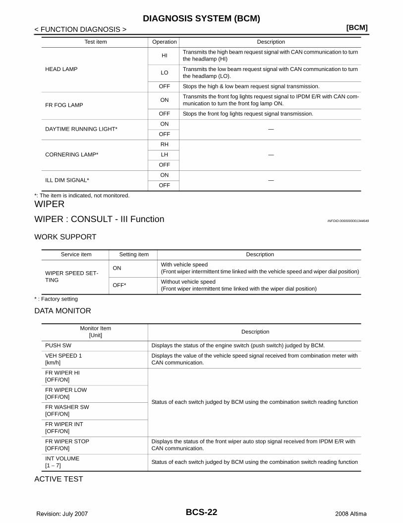
HEAD LAMP
HITransmits the high beam request signal with CAN communication to turn the headlamp (HI)
LOTransmits the low beam request signal with CAN communication to turn the headlamp (LO).
OFF Stops the high & low beam request signal transmission.
FR FOG LAMPON
Transmits the front fog lights request signal to IPDM E/R with CAN com-munication to turn the front fog lamp ON.
OFF Stops the front fog lights request signal transmission.
DAYTIME RUNNING LIGHT*ON
—OFF
CORNERING LAMP*
RH
—LH
OFF
ILL DIM SIGNAL*ON
—OFF
Test item Operation Description
Service item Setting item Description
WIPER SPEED SET-TING
ONWith vehicle speed(Front wiper intermittent time linked with the vehicle speed and wiper dial position)
OFF*Without vehicle speed(Front wiper intermittent time linked with the wiper dial position)
Monitor Item[Unit]
Description
PUSH SW Displays the status of the engine switch (push switch) judged by BCM.
VEH SPEED 1[km/h]
Displays the value of the vehicle speed signal received from combination meter with CAN communication.
FR WIPER HI[OFF/ON]
Status of each switch judged by BCM using the combination switch reading function
FR WIPER LOW[OFF/ON]
FR WASHER SW[OFF/ON]
FR WIPER INT[OFF/ON]
FR WIPER STOP[OFF/ON]
Displays the status of the front wiper auto stop signal received from IPDM E/R with CAN communication.
INT VOLUME[1 − 7]
Status of each switch judged by BCM using the combination switch reading function
BCS-22

CS
DIAGNOSIS SYSTEM (BCM)[BCM]
C
D
E
F
G
H
I
J
K
L
B
A
O
P
N
B
< FUNCTION DIAGNOSIS >
FLASHER
FLASHER : CONSULT-III Function INFOID:0000000001344650
Work support
* : Initial setting
Data monitor
Active test
AIR CONDITIONER
AIR CONDITIONER : CONSULT-III Function (BCM - AUTO AIR CONDITIONER)INFOID:0000000003183910
DATA MONITOR
Test item Operation Description
FRONT WIPER
HITransmits the front wiper request signal (HI) to IPDM E/R with CAN communication to op-erate the front wiper HI operation.
LOTransmits the front wiper request signal (LO) to IPDM E/R with CAN communication to operate the front wiper LO operation.
INTTransmits the front wiper request signal (INT) to IPDM E/R with CAN communication to operate the front wiper INT operation.
OFF Stops transmitting the front wiper request signal to stop the front wiper operation.
Service item Setting item Setting
HAZARD ANSWER BACK
LOCK ONLY* Activated when locking.
Sets the hazard warning lamp answer back activation when the door is lock/unlock with the request switch or the key fob.
UNLK ONLYActivated when unlock-ing.
LOCK/UNLKActivated when locking/unlocking
OFF Not activated
Monitor item[Unit]
Description
TURN SIGNAL R [ON/OFF]
Each switch condition that BCM judges from the combination switch reading functionTURN SIGNAL L [ON/OFF]
HAZARD SW[ON/OFF]
The switch status input from the hazard warning switch
RKE LOCK[ON/OFF]
The lock signal status received from the keyless receiver
RKE UNLOCK[ON/OFF]
The unock signal status received from the keyless receiver
RKE PANIC[ON/OFF]
The panic alarm signal status received from the keyless receiver
Test item Operation Description
FLASHER
RH Blinks right turn signal lamp.
LH Blinks left turn signal lamp.
OFF Turns turn signal lamps (right and left) OFF.
BCS-23
[BCM]DIAGNOSIS SYSTEM (BCM)
< FUNCTION DIAGNOSIS >
INTELLIGENT KEY
INTELLIGENT KEY : CONSULT-III Function (BCM - INTELLIGENT KEY) INFOID:0000000003183911
DATA MONITOR
COMB SW
COMB SW : CONSULT-III Function INFOID:0000000001344651
DATA MONITOR
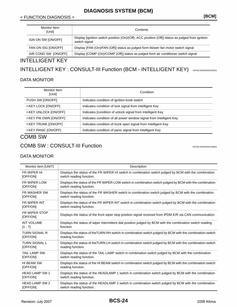
Monitor Item[Unit]
Contents
IGN ON SW [ON/OFF]Display [ignition switch position (On)/(Off), ACC position (Off)] status as judged from ignition switch signal
FAN ON SIG [ON/OFF] Display [FAN (On)/FAN (Off)] status as judged form blower fan motor switch signal
AIR COND SW [ON/OFF] Display [COMP (On)/COMP (Off)] status as judged form air conditioner switch signal
Monitor Item[Unit]
Condition
PUSH SW [ON/OFF] Indicates condition of ignition knob switch
I-KEY LOCK [ON/OFF] Indicates condition of lock signal from Intelligent Key
I-KEY UNLOCK [ON/OFF] Indicates [condition of unlock signal from Intelligent Key
I-KEY PW DWN [ON/OFF] Indicates condition of all power window signal from Intelligent Key
I-KEY TRUNK [ON/OFF] Indicates condition of trunk open signal from Intelligent Key
I-KEY PANIC [ON/OFF] Indicates condition of panic signal from Intelligent Key
Monitor item [UNIT] Description
FR WIPER HI[OFF/ON]
Displays the status of the FR WIPER HI switch in combination switch judged by BCM with the combination switch reading function.
FR WIPER LOW[OFF/ON]
Displays the status of the FR WIPER LOW switch in combination switch judged by BCM with the combination switch reading function.
FR WASHER SW[OFF/ON]
Displays the status of the FR WASHER switch in combination switch judged by BCM with the combination switch reading function.
FR WIPER INT[OFF/ON]
Displays the status of the FR WIPER INT switch in combination switch judged by BCM with the combination switch reading function.
FR WIPER STOP[OFF/ON]
Displays the status of the front wiper stop position signal received from IPDM E/R via CAN communication.
INT VOLUME[1 - 7]
Displays the status of wiper intermittent dial position judged by BCM with the combination switch reading function
TURN SIGNAL R[OFF/ON]
Displays the status of theTURN RH switch in combination switch judged by BCM with the combination switch reading function.
TURN SIGNAL L[OFF/ON]
Displays the status of theTURN LH switch in combination switch judged by BCM with the combination switch reading function.
TAIL LAMP SW[OFF/ON]
Displays the status of the TAIL LAMP switch in combination switch judged by BCM with the combination switch reading function.
HI BEAM SW[OFF/ON]
Displays the status of the HI BEAM switch in combination switch judged by BCM with the combination switch reading function.
HEAD LAMP SW 1[OFF/ON]
Displays the status of the HEADLAMP 1 switch in combination switch judged by BCM with the combination switch reading function.
HEAD LAMP SW 2[OFF/ON]
Displays the status of the HEADLAMP 2 switch in combination switch judged by BCM with the combination switch reading function.
BCS-24
CS
DIAGNOSIS SYSTEM (BCM)[BCM]
C
D
E
F
G
H
I
J
K
L
B
A
O
P
N
B
< FUNCTION DIAGNOSIS >
*: With autolamp system
BCM
BCM : CONSULT-III Function (BCM - BCM) INFOID:0000000003183912
WORK SUPPORT
IMMU
IMMU : CONSULT-III Function (BCM - IMMU) INFOID:0000000003183913
DATA MONITOR
ACTIVE TEST
BATTERY SAVER
BATTERY SAVER : CONSULT-III Function INFOID:0000000001344653
WORK SUPPORT
* : Initial setting
DATA MONITOR
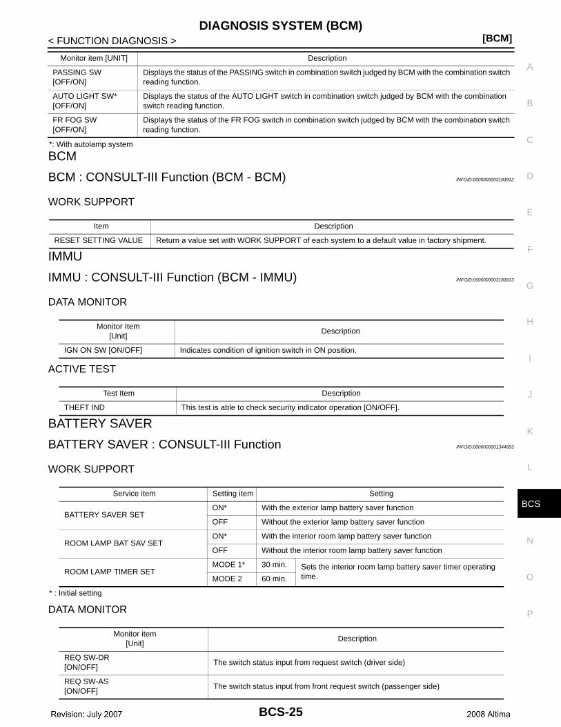
PASSING SW[OFF/ON]
Displays the status of the PASSING switch in combination switch judged by BCM with the combination switch reading function.
AUTO LIGHT SW*[OFF/ON]
Displays the status of the AUTO LIGHT switch in combination switch judged by BCM with the combination switch reading function.
FR FOG SW[OFF/ON]
Displays the status of the FR FOG switch in combination switch judged by BCM with the combination switch reading function.
Monitor item [UNIT] Description
Item Description
RESET SETTING VALUE Return a value set with WORK SUPPORT of each system to a default value in factory shipment.
Monitor Item[Unit]
Description
IGN ON SW [ON/OFF] Indicates condition of ignition switch in ON position.
Test Item Description
THEFT IND This test is able to check security indicator operation [ON/OFF].
Service item Setting item Setting
BATTERY SAVER SETON* With the exterior lamp battery saver function
OFF Without the exterior lamp battery saver function
ROOM LAMP BAT SAV SETON* With the interior room lamp battery saver function
OFF Without the interior room lamp battery saver function
ROOM LAMP TIMER SETMODE 1* 30 min. Sets the interior room lamp battery saver timer operating
time. MODE 2 60 min.
Monitor item[Unit]
Description
REQ SW-DR[ON/OFF]
The switch status input from request switch (driver side)
REQ SW-AS[ON/OFF]
The switch status input from front request switch (passenger side)
BCS-25
[BCM]DIAGNOSIS SYSTEM (BCM)
< FUNCTION DIAGNOSIS >
ACTIVE TEST
* : Each lamp switch is in ON position.
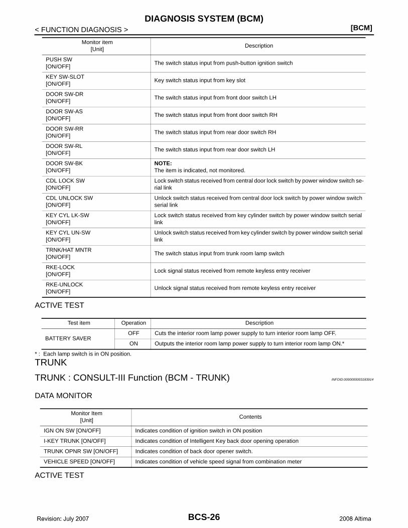
TRUNK
TRUNK : CONSULT-III Function (BCM - TRUNK) INFOID:0000000003183914
DATA MONITOR
ACTIVE TEST
PUSH SW[ON/OFF]
The switch status input from push-button ignition switch
KEY SW-SLOT[ON/OFF]
Key switch status input from key slot
DOOR SW-DR[ON/OFF]
The switch status input from front door switch LH
DOOR SW-AS[ON/OFF]
The switch status input from front door switch RH
DOOR SW-RR[ON/OFF]
The switch status input from rear door switch RH
DOOR SW-RL[ON/OFF]
The switch status input from rear door switch LH
DOOR SW-BK[ON/OFF]
NOTE:The item is indicated, not monitored.
CDL LOCK SW[ON/OFF]
Lock switch status received from central door lock switch by power window switch se-rial link
CDL UNLOCK SW[ON/OFF]
Unlock switch status received from central door lock switch by power window switch serial link
KEY CYL LK-SW[ON/OFF]
Lock switch status received from key cylinder switch by power window switch serial link
KEY CYL UN-SW[ON/OFF]
Unlock switch status received from key cylinder switch by power window switch serial link
TRNK/HAT MNTR[ON/OFF]
The switch status input from trunk room lamp switch
RKE-LOCK[ON/OFF]
Lock signal status received from remote keyless entry receiver
RKE-UNLOCK[ON/OFF]
Unlock signal status received from remote keyless entry receiver
Monitor item[Unit]
Description
Test item Operation Description
BATTERY SAVEROFF Cuts the interior room lamp power supply to turn interior room lamp OFF.
ON Outputs the interior room lamp power supply to turn interior room lamp ON.*
Monitor Item[Unit]
Contents
IGN ON SW [ON/OFF] Indicates condition of ignition switch in ON position
I-KEY TRUNK [ON/OFF] Indicates condition of Intelligent Key back door opening operation
TRUNK OPNR SW [ON/OFF] Indicates condition of back door opener switch.
VEHICLE SPEED [ON/OFF] Indicates condition of vehicle speed signal from combination meter
BCS-26
CS
DIAGNOSIS SYSTEM (BCM)[BCM]
C
D
E
F
G
H
I
J
K
L
B
A
O
P
N
B
< FUNCTION DIAGNOSIS >
THEFT ALM
THEFT ALM : CONSULT-III Function (BCM - THEFT ALM) INFOID:0000000003183915
WORK SUPPORT
RETAINED PWR
RETAINED PWR : CONSULT-III Function (BCM - RETAINED PWR) INFOID:0000000003183916
Data monitor
SIGNAL BUFFER
SIGNAL BUFFER : CONSULT-III Function INFOID:0000000001344654
DATA MONITOR
ACTIVE TEST
AIR PRESSURE MONITOR
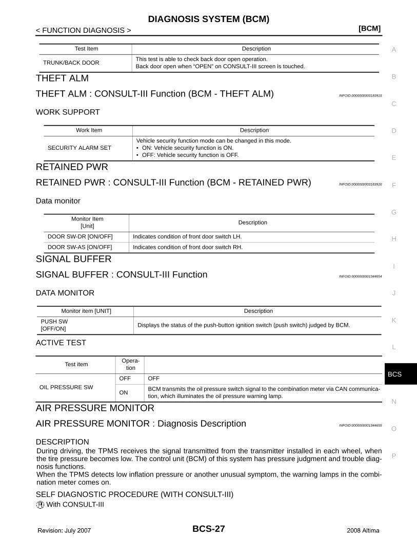
AIR PRESSURE MONITOR : Diagnosis Description INFOID:0000000001344655
DESCRIPTIONDuring driving, the TPMS receives the signal transmitted from the transmitter installed in each wheel, whenthe tire pressure becomes low. The control unit (BCM) of this system has pressure judgment and trouble diag-nosis functions.When the TPMS detects low inflation pressure or another unusual symptom, the warning lamps in the combi-nation meter comes on.
SELF DIAGNOSTIC PROCEDURE (WITH CONSULT-III) With CONSULT-III
Test Item Description
TRUNK/BACK DOORThis test is able to check back door open operation.Back door open when “OPEN” on CONSULT-III screen is touched.
Work Item Description
SECURITY ALARM SETVehicle security function mode can be changed in this mode.• ON: Vehicle security function is ON.• OFF: Vehicle security function is OFF.
Monitor Item[Unit]
Description
DOOR SW-DR [ON/OFF] Indicates condition of front door switch LH.
DOOR SW-AS [ON/OFF] Indicates condition of front door switch RH.
Monitor item [UNIT] Description
PUSH SW[OFF/ON]
Displays the status of the push-button ignition switch (push switch) judged by BCM.
Test itemOpera-
tion
OIL PRESSURE SW
OFF OFF
ONBCM transmits the oil pressure switch signal to the combination meter via CAN communica-tion, which illuminates the oil pressure warning lamp.
BCS-27

[BCM]DIAGNOSIS SYSTEM (BCM)
< FUNCTION DIAGNOSIS >• Touch “SELF-DIAG RESULTS” display shows malfunction experienced since the last erasing operation.
Refer to BCS-85, "DTC Index".
SELF DIAGNOSTIC PROCEDURE (WITHOUT CONSULT-III) Without CONSULT-III
To start the self-diagnostic results mode, ground terminal of the tire pressure warning check connector. Themalfunction location is indicated by the warning lamp flashing.
NOTE:When the low tire warning lamp flashes 5 Hz and continues repeating it, the system is normal.
SEIA0745E
Flickering pattern
Items Diagnostic items detected when··· Check item
15 Tire pressure value (Front LH) Front LH tire pressure drops to 181 kPa (1.8 kg/cm, 26 psi) or less.
–16 Tire pressure value (Front RH) Front RH tire pressure drops to 181 kPa (1.8 kg/cm, 26 psi) or less.
17 Tire pressure value (Rear RH) Rear RH tire pressure drops to 181 kPa (1.8 kg/cm, 26 psi) or less.
18 Tire pressure value (Rear LH) Rear LH tire pressure drops to 181 kPa (1.8 kg/cm, 26 psi) or less.
21 Transmitter no data (Front LH) Data from front LH transmitter can not be received.
WT-2422 Transmitter no data (Front RH) Data from front RH transmitter can not be received.
23 Transmitter no data (Rear RH) Data from Rear RH transmitter can not be received.
24 Transmitter no data (Rear LH) Data from Rear LH transmitter can not be received.
31Transmitter checksum error (Front LH)
Checksum data from front LH transmitter is malfunctioning.
WT-24
32Transmitter checksum error (Front RH)
Checksum data from front RH transmitter is malfunctioning.
33Transmitter checksum error (Rear RH)
Checksum data from rear RH transmitter is malfunctioning.
34Transmitter checksum error (Rear LH)
Checksum data from rear RH transmitter is malfunctioning.
35Transmitter pressure data error (Front LH)
Air pressure data from front LH transmitter is malfunction.
WT-24
36Transmitter pressure data error (Front RH)
Air pressure data from front RH transmitter is malfunction.
37Transmitter pressure data error (Rear RH)
Air pressure data from rear RH transmitter is malfunction.
38Transmitter pressure data error (Rear LH)
Air pressure data from rear LH transmitter is malfunction.
41Transmitter function code error (Front LH)
Function code data from front LH transmitter is malfunction.
WT-24
42Transmitter function code error (Front RH)
Function code data from front RH transmitter is malfunction.
43Transmitter function code error (Rear RH)
Function code data from rear RH transmitter is malfunction.
44Transmitter function code error (Rear LH)
Function code data from rear LH transmitter is malfunction.
BCS-28
CS
DIAGNOSIS SYSTEM (BCM)[BCM]
C
D
E
F
G
H
I
J
K
L
B
A
O
P
N
B
< FUNCTION DIAGNOSIS >
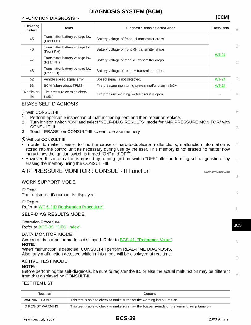
ERASE SELF-DIAGNOSIS
With CONSULT-III1. Perform applicable inspection of malfunctioning item and then repair or replace. 2. Turn ignition switch “ON” and select “SELF-DIAG RESULTS” mode for “AIR PRESSURE MONITOR” with
CONSULT-III.3. Touch “ERASE” on CONSULT-III screen to erase memory.
Without CONSULT-III• In order to make it easier to find the cause of hard-to-duplicate malfunctions, malfunction information is
stored into the control unit as necessary during use by the user. This memory is not erased no matter howmany times the ignition switch is turned “ON” and“OFF”.
• However, this information is erased by turning ignition switch “OFF” after performing self-diagnostic or byerasing the memory using the CONSULT-III.
AIR PRESSURE MONITOR : CONSULT-III Function INFOID:0000000001344656
WORK SUPPORT MODE
ID ReadThe registered ID number is displayed.
ID RegistRefer to WT-6, "ID Registration Procedure".
SELF-DIAG RESULTS MODE
Operation ProcedureRefer to BCS-85, "DTC Index".
DATA MONITOR MODEScreen of data monitor mode is displayed. Refer to BCS-41, "Reference Value".NOTE:When malfunction is detected, CONSULT-III perform REAL-TIME DIAGNOSIS.Also, any malfunction detected while in this mode will be displayed at real time.
ACTIVE TEST MODENOTE:Before performing the self-diagnosis, be sure to register the ID, or else the actual malfunction may be differentfrom that displayed on CONSULT-III.
TEST ITEM LIST
45Transmitter battery voltage low (Front LH)
Battery voltage of front LH transmitter drops.
WT-24
46Transmitter battery voltage low (Front RH)
Battery voltage of front RH transmitter drops.
47Transmitter battery voltage low (Rear RH)
Battery voltage of rear RH transmitter drops.
48Transmitter battery voltage low (Rear LH)
Battery voltage of rear LH transmitter drops.
52 Vehicle speed signal error Speed signal is not detected. WT-24
53 BCM failure about TPMS Tire pressure monitoring system malfunction in BCM WT-24
No flicker-ing
Tire pressure warning check switch
Tire pressure warning switch circuit is open. –
Flickering pattern
Items Diagnostic items detected when··· Check item
Test item Content
WARNING LAMP This test is able to check to make sure that the warning lamp turns on.
ID REGIST WARNING This test is able to check to make sure that the buzzer sounds or the warning lamp turns on.
BCS-29

[BCM]DIAGNOSIS SYSTEM (BCM)
< FUNCTION DIAGNOSIS >
FUSE, FUSIBLE LINK
FUSE, FUSIBLE LINK : CONSULT-III Function INFOID:0000000001344652
WORK SUPPORT
FLASHER This test is able to check to make sure that each turn signal lamp turns on.
HORN This test is able to check to make sure that the horn sounds.
Test item Content
Item Description
RESET SETTING VALUE Return a value set with WORK SUPPORT of each system to a default value in factory shipment.
BCS-30
CS
U1000 CAN COMM CIRCUIT[BCM]
C
D
E
F
G
H
I
J
K
L
B
A
O
P
N
B
< COMPONENT DIAGNOSIS >
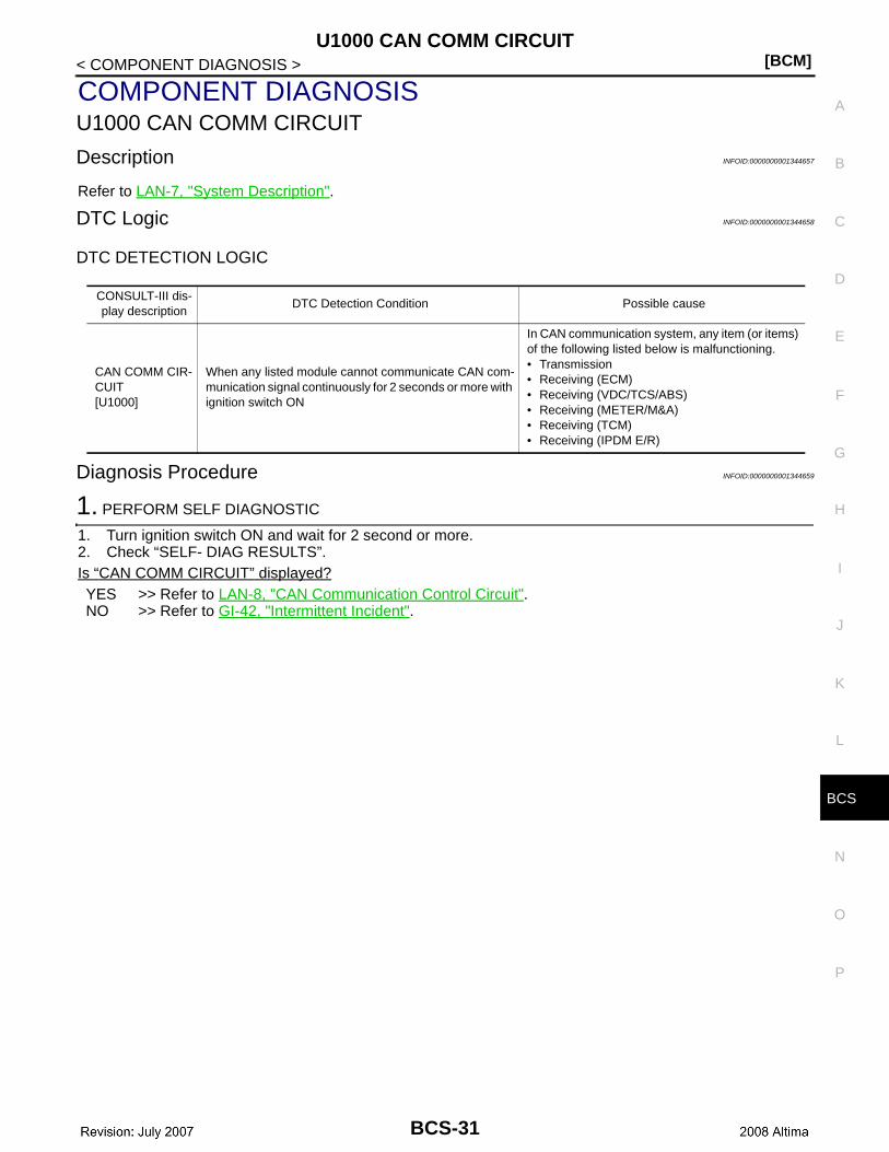
COMPONENT DIAGNOSISU1000 CAN COMM CIRCUIT
Description INFOID:0000000001344657
Refer to LAN-7, "System Description".
DTC Logic INFOID:0000000001344658
DTC DETECTION LOGIC
Diagnosis Procedure INFOID:0000000001344659
1. PERFORM SELF DIAGNOSTIC
1. Turn ignition switch ON and wait for 2 second or more.2. Check “SELF- DIAG RESULTS”.Is “CAN COMM CIRCUIT” displayed?YES >> Refer to LAN-8, "CAN Communication Control Circuit".NO >> Refer to GI-42, "Intermittent Incident".
CONSULT-III dis-play description
DTC Detection Condition Possible cause
CAN COMM CIR-CUIT[U1000]
When any listed module cannot communicate CAN com-munication signal continuously for 2 seconds or more with ignition switch ON
In CAN communication system, any item (or items) of the following listed below is malfunctioning.• Transmission• Receiving (ECM)• Receiving (VDC/TCS/ABS)• Receiving (METER/M&A)• Receiving (TCM)• Receiving (IPDM E/R)
BCS-31

[BCM]U1010 CONTROL UNIT (CAN)
< COMPONENT DIAGNOSIS >
U1010 CONTROL UNIT (CAN)
DTC Logic INFOID:0000000001344660
DTC DETECTION LOGIC
Diagnosis Procedure INFOID:0000000001344661
1. REPLACE BCM
When DTC U1010 is detected, replace BCM.
>> Replace BCM. Refer to BCS-88, "Removal and Installation".
CONSULT-III display description
DTC Detection Condition Possible cause
CAN COMM CIRCUIT[U1010]
BCM detected internal CAN communication circuit malfunction. BCM
BCS-32
CS
U0415 VEHICLE SPEED SIG[BCM]
C
D
E
F
G
H
I
J
K
L
B
A
O
P
N
B
< COMPONENT DIAGNOSIS >
U0415 VEHICLE SPEED SIG
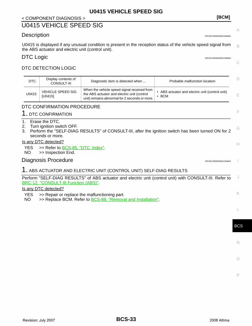
Description INFOID:0000000001344662
U0415 is displayed if any unusual condition is present in the reception status of the vehicle speed signal fromthe ABS actuator and electric unit (control unit).
DTC Logic INFOID:0000000001344663
DTC DETECTION LOGIC
DTC CONFIRMATION PROCEDURE
1. DTC CONFIRMATION
1. Erase the DTC.2. Turn ignition switch OFF.3. Perform the "SELF-DIAG RESULTS" of CONSULT-III, after the ignition switch has been turned ON for 2
seconds or more.Is any DTC detected?YES >> Refer to BCS-85, "DTC Index".NO >> Inspection End.
Diagnosis Procedure INFOID:0000000001344664
1. ABS ACTUATOR AND ELECTRIC UNIT (CONTROL UNIT) SELF-DIAG RESULTS
Perform "SELF-DIAG RESULTS" of ABS actuator and electric unit (control unit) with CONSULT-III. Refer toBRC-12, "CONSULT-III Function (ABS)".Is any DTC detected?YES >> Repair or replace the malfunctioning part.NO >> Replace BCM. Refer to BCS-88, "Removal and Installation".
DTCDisplay contents of
CONSULT-IIIDiagnostic item is detected when ... Probable malfunction location
U0415VEHICLE SPEED SIG[U0415]
When the vehicle speed signal received from the ABS actuator and electric unit (control unit) remains abnormal for 2 seconds or more.
• ABS actuator and electric unit (control unit)• BCM
BCS-33

[BCM]B2562 LOW VOLTAGE
< COMPONENT DIAGNOSIS >
B2562 LOW VOLTAGE
DTC Logic INFOID:0000000001344665
DTC DETECTION LOGIC
DTC CONFIRMATION PROCEDURE
1. DTC CONFIRMATION
1. Erase DTC.2. Turn ignition switch OFF.3. Perform the "SELF-DIAG RESULTS" of CONSULT-III, after the ignition switch has been turned ON for 1.5
seconds or more.Is any DTC detected?YES >> Refer to BCS-34, "Diagnosis Procedure".NO >> Inspection End.
Diagnosis Procedure INFOID:0000000001344666
1. CHECK BATTERY VOLTAGE
Check battery voltage. Is battery voltage less than 8.8V?Yes >> Charge battery and retest. Refer to PG-70, "Work Flow".No >> GO TO 2
2. CHECK POWER SUPPLY CIRCUIT
Check BCM power supply circuit. Refer to BCS-36, "Diagnosis Procedure".Is the circuit OK?Yes >> Replace BCM. Refer to BCS-88, "Removal and Installation".No >> Repair or replace the malfunctioning part.
Special Repair Requirement INFOID:0000000001344667
1. REQUIRED WORK WHEN REPLACING BCM
Initialize control unit. Refer to CONSULT-III Operation Manual.
>> Work end.
DTCDisplay contents of
CONSULT-IIIDiagnostic item is detected when ... Possible cause
B2562 LOW VOLTAGEWhen the power supply voltage to BCM remains less than 8.8 V for 1.5 seconds or more
Harness or connector (power supply circuit)
BCS-34
CS
B2563 HI VOLTAGE[BCM]
C
D
E
F
G
H
I
J
K
L
B
A
O
P
N
B
< COMPONENT DIAGNOSIS >
B2563 HI VOLTAGE
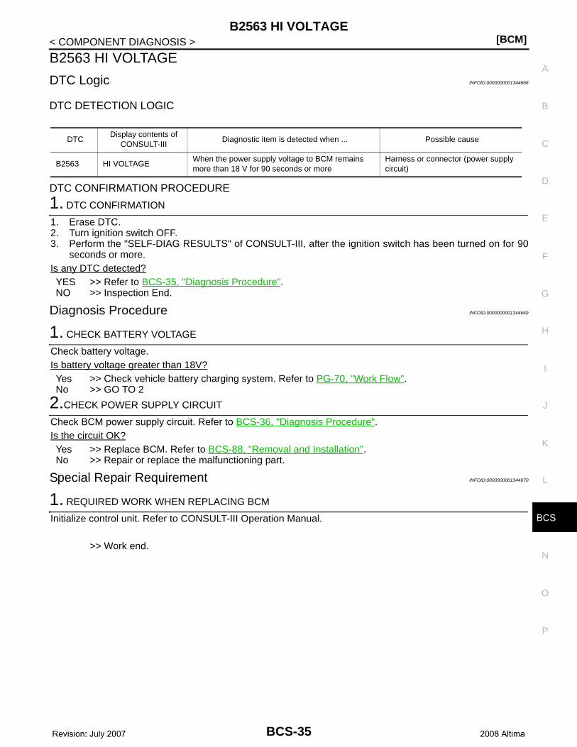
DTC Logic INFOID:0000000001344668
DTC DETECTION LOGIC
DTC CONFIRMATION PROCEDURE
1. DTC CONFIRMATION
1. Erase DTC.2. Turn ignition switch OFF.3. Perform the "SELF-DIAG RESULTS" of CONSULT-III, after the ignition switch has been turned on for 90
seconds or more. Is any DTC detected?YES >> Refer to BCS-35, "Diagnosis Procedure".NO >> Inspection End.
Diagnosis Procedure INFOID:0000000001344669
1. CHECK BATTERY VOLTAGE
Check battery voltage.Is battery voltage greater than 18V?Yes >> Check vehicle battery charging system. Refer to PG-70, "Work Flow".No >> GO TO 2
2.CHECK POWER SUPPLY CIRCUIT
Check BCM power supply circuit. Refer to BCS-36, "Diagnosis Procedure".Is the circuit OK?Yes >> Replace BCM. Refer to BCS-88, "Removal and Installation".No >> Repair or replace the malfunctioning part.
Special Repair Requirement INFOID:0000000001344670
1. REQUIRED WORK WHEN REPLACING BCM
Initialize control unit. Refer to CONSULT-III Operation Manual.
>> Work end.
DTCDisplay contents of
CONSULT-IIIDiagnostic item is detected when ... Possible cause
B2563 HI VOLTAGEWhen the power supply voltage to BCM remains more than 18 V for 90 seconds or more
Harness or connector (power supply circuit)
BCS-35

[BCM]POWER SUPPLY AND GROUND CIRCUIT
< COMPONENT DIAGNOSIS >
POWER SUPPLY AND GROUND CIRCUIT
Diagnosis Procedure INFOID:0000000001344671
1. CHECK FUSE AND FUSIBLE LINK
Check if the following BCM fuse or fusible link are blown.
Is the fuse or fusible link blown?YES >> Replace the blown fuse or fusible link after repairing the affected circuit.NO >> GO TO 2
2. CHECK POWER SUPPLY CIRCUIT
1. Turn ignition switch OFF.2. Disconnect BCM.3. Check voltage between BCM harness connector and ground.
Is the measurement normal?YES >> GO TO 3NO >> Repair or replace harness.
3. CHECK GROUND CIRCUIT
Check continuity between BCM harness connector and ground.
Does continuity exist?YES >> Inspection End.NO >> Repair or replace harness.
Special Repair Requirement INFOID:0000000001344672
1. REQUIRED WORK WHEN REPLACING BCM
Initialize control unit. Refer to CONSULT-III Operation Manual.
>> Work end.
Terminal No. Signal name Fuse and fusible link No.
1Battery power supply
I
11 10
Terminals
Voltage(Approx.)
(+) (−)
BCM
GroundConnector Terminal
M16 1Battery voltage
M17 11ALCIA0025ZZ
BCM
GroundContinuity
Connector Terminal
M17 13 Yes
ALCIA0024ZZ
BCS-36
CS
COMBINATION SWITCH INPUT CIRCUIT[BCM]
C
D
E
F
G
H
I
J
K
L
B
A
O
P
N
B
< COMPONENT DIAGNOSIS >
COMBINATION SWITCH INPUT CIRCUIT
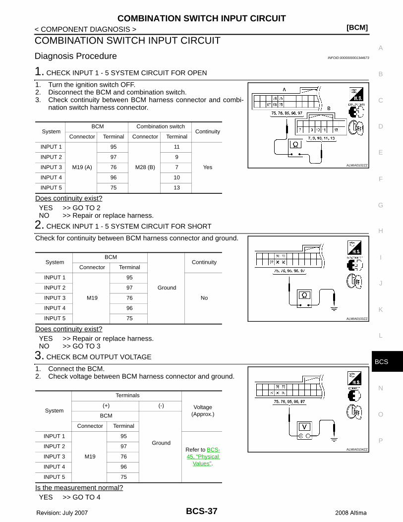
Diagnosis Procedure INFOID:0000000001344673
1. CHECK INPUT 1 - 5 SYSTEM CIRCUIT FOR OPEN
1. Turn the ignition switch OFF.2. Disconnect the BCM and combination switch.3. Check continuity between BCM harness connector and combi-
nation switch harness connector.
Does continuity exist?YES >> GO TO 2NO >> Repair or replace harness.
2. CHECK INPUT 1 - 5 SYSTEM CIRCUIT FOR SHORT
Check for continuity between BCM harness connector and ground.
Does continuity exist?YES >> Repair or replace harness.NO >> GO TO 3
3. CHECK BCM OUTPUT VOLTAGE
1. Connect the BCM.2. Check voltage between BCM harness connector and ground.
Is the measurement normal?YES >> GO TO 4
SystemBCM Combination switch
ContinuityConnector Terminal Connector Terminal
INPUT 1
M19 (A)
95
M28 (B)
11
Yes
INPUT 2 97 9
INPUT 3 76 7
INPUT 4 96 10
INPUT 5 75 13
ALMIA0102ZZ
SystemBCM
Ground
ContinuityConnector Terminal
INPUT 1
M19
95
No
INPUT 2 97
INPUT 3 76
INPUT 4 96
INPUT 5 75 ALMIA0103ZZ
System
Terminals
Voltage(Approx.)
(+) (-)
BCM
Ground
Connector Terminal
INPUT 1
M19
95
Refer to BCS-45, "Physical
Values".
INPUT 2 97
INPUT 3 76
INPUT 4 96
INPUT 5 75
ALMIA0104ZZ
BCS-37
[BCM]COMBINATION SWITCH INPUT CIRCUIT
< COMPONENT DIAGNOSIS >NO >> Replace BCM. Refer to BCS-88, "Removal and Installation".
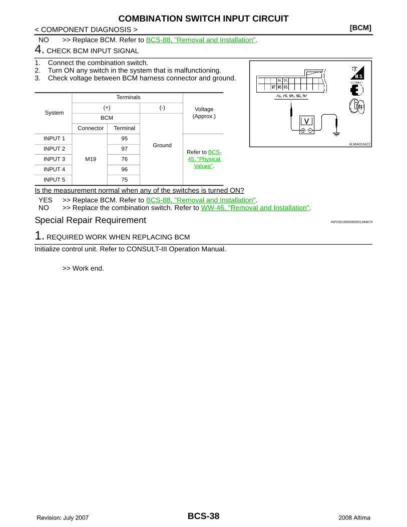
4. CHECK BCM INPUT SIGNAL
1. Connect the combination switch.2. Turn ON any switch in the system that is malfunctioning.3. Check voltage between BCM harness connector and ground.
Is the measurement normal when any of the switches is turned ON?YES >> Replace BCM. Refer to BCS-88, "Removal and Installation".NO >> Replace the combination switch. Refer to WW-46, "Removal and Installation".
Special Repair Requirement INFOID:0000000001344674
1. REQUIRED WORK WHEN REPLACING BCM
Initialize control unit. Refer to CONSULT-III Operation Manual.
>> Work end.
System
Terminals
Voltage(Approx.)
(+) (-)
BCM
Ground
Connector Terminal
INPUT 1
M19
95
Refer to BCS-45, "Physical
Values".
INPUT 2 97
INPUT 3 76
INPUT 4 96
INPUT 5 75
ALMIA0104ZZ
BCS-38
CS
COMBINATION SWITCH OUTPUT CIRCUIT[BCM]
C
D
E
F
G
H
I
J
K
L
B
A
O
P
N
B
< COMPONENT DIAGNOSIS >
COMBINATION SWITCH OUTPUT CIRCUIT
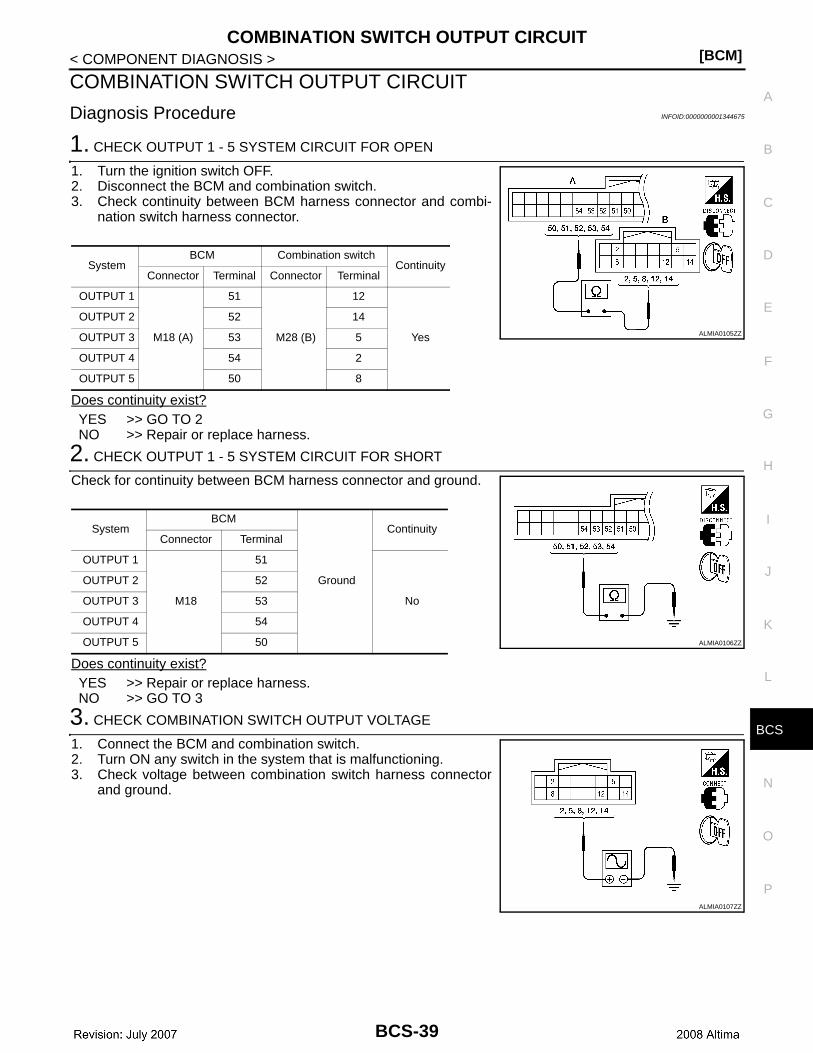
Diagnosis Procedure INFOID:0000000001344675
1. CHECK OUTPUT 1 - 5 SYSTEM CIRCUIT FOR OPEN
1. Turn the ignition switch OFF.2. Disconnect the BCM and combination switch.3. Check continuity between BCM harness connector and combi-
nation switch harness connector.
Does continuity exist?YES >> GO TO 2NO >> Repair or replace harness.
2. CHECK OUTPUT 1 - 5 SYSTEM CIRCUIT FOR SHORT
Check for continuity between BCM harness connector and ground.
Does continuity exist?YES >> Repair or replace harness.NO >> GO TO 3
3. CHECK COMBINATION SWITCH OUTPUT VOLTAGE
1. Connect the BCM and combination switch.2. Turn ON any switch in the system that is malfunctioning.3. Check voltage between combination switch harness connector
and ground.
SystemBCM Combination switch
ContinuityConnector Terminal Connector Terminal
OUTPUT 1
M18 (A)
51
M28 (B)
12
Yes
OUTPUT 2 52 14
OUTPUT 3 53 5
OUTPUT 4 54 2
OUTPUT 5 50 8
ALMIA0105ZZ
SystemBCM
Ground
ContinuityConnector Terminal
OUTPUT 1
M18
51
No
OUTPUT 2 52
OUTPUT 3 53
OUTPUT 4 54
OUTPUT 5 50 ALMIA0106ZZ
ALMIA0107ZZ
BCS-39
[BCM]COMBINATION SWITCH OUTPUT CIRCUIT
< COMPONENT DIAGNOSIS >
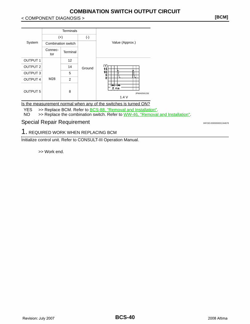
Is the measurement normal when any of the switches is turned ON?YES >> Replace BCM. Refer to BCS-88, "Removal and Installation".NO >> Replace the combination switch. Refer to WW-46, "Removal and Installation".
Special Repair Requirement INFOID:0000000001344676
1. REQUIRED WORK WHEN REPLACING BCM
Initialize control unit. Refer to CONSULT-III Operation Manual.
>> Work end.
System
Terminals
Value (Approx.)
(+) (-)
Combination switch
Ground
Connec-tor
Terminal
OUTPUT 1
M28
12
1.4 V
OUTPUT 2 14
OUTPUT 3 5
OUTPUT 4 2
OUTPUT 5 8JPMIA0041GB
BCS-40
CS
BCM (BODY CONTROL MODULE)[BCM]
C
D
E
F
G
H
I
J
K
L
B
A
O
P
N
B
< ECU DIAGNOSIS >
ECU DIAGNOSISBCM (BODY CONTROL MODULE)
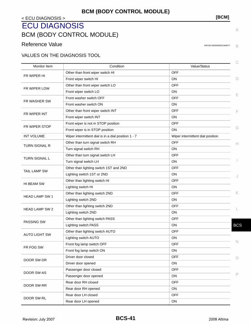
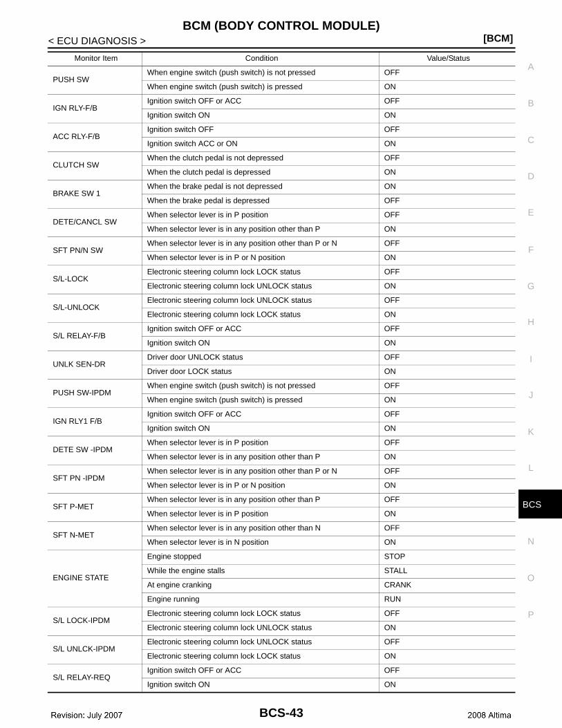
Reference Value INFOID:0000000001344677
VALUES ON THE DIAGNOSIS TOOL
Monitor Item Condition Value/Status
FR WIPER HIOther than front wiper switch HI OFF
Front wiper switch HI ON
FR WIPER LOWOther than front wiper switch LO OFF
Front wiper switch LO ON
FR WASHER SWFront washer switch OFF OFF
Front washer switch ON ON
FR WIPER INTOther than front wiper switch INT OFF
Front wiper switch INT ON
FR WIPER STOPFront wiper is not in STOP position OFF
Front wiper is in STOP position ON
INT VOLUME Wiper intermittent dial is in a dial position 1 - 7 Wiper intermittent dial position
TURN SIGNAL ROther than turn signal switch RH OFF
Turn signal switch RH ON
TURN SIGNAL LOther than turn signal switch LH OFF
Turn signal switch LH ON
TAIL LAMP SWOther than lighting switch 1ST and 2ND OFF
Lighting switch 1ST or 2ND ON
HI BEAM SWOther than lighting switch HI OFF
Lighting switch HI ON
HEAD LAMP SW 1Other than lighting switch 2ND OFF
Lighting switch 2ND ON
HEAD LAMP SW 2Other than lighting switch 2ND OFF
Lighting switch 2ND ON
PASSING SWOther than lighting switch PASS OFF
Lighting switch PASS ON
AUTO LIGHT SWOther than lighting switch AUTO OFF
Lighting switch AUTO ON
FR FOG SWFront fog lamp switch OFF OFF
Front fog lamp switch ON ON
DOOR SW-DRDriver door closed OFF
Driver door opened ON
DOOR SW-ASPassenger door closed OFF
Passenger door opened ON
DOOR SW-RRRear door RH closed OFF
Rear door RH opened ON
DOOR SW-RLRear door LH closed OFF
Rear door LH opened ON
BCS-41
[BCM]BCM (BODY CONTROL MODULE)
< ECU DIAGNOSIS >
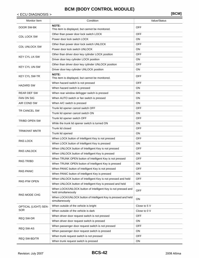
DOOR SW-BKNOTE:This item is displayed, but cannot be monitored.
OFF
CDL LOCK SWOther than power door lock switch LOCK OFF
Power door lock switch LOCK ON
CDL UNLOCK SWOther than power door lock switch UNLOCK OFF
Power door lock switch UNLOCK ON
KEY CYL LK-SWOther than driver door key cylinder LOCK position OFF
Driver door key cylinder LOCK position ON
KEY CYL UN-SWOther than driver door key cylinder UNLOCK position OFF
Driver door key cylinder UNLOCK position ON
KEY CYL SW-TRNOTE:This item is displayed, but cannot be monitored.
OFF
HAZARD SWWhen hazard switch is not pressed OFF
When hazard switch is pressed ON
REAR DEF SW When rear window defogger switch is pressed ON
FAN ON SIG When AUTO switch or fan switch is pressed ON
AIR COND SW When A/C switch is pressed ON
TR CANCEL SWTrunk lid opener cancel switch OFF OFF
Trunk lid opener cancel switch ON ON
TR/BD OPEN SWTrunk lid opener switch OFF OFF
While the trunk lid opener switch is turned ON ON
TRNK/HAT MNTRTrunk lid closed OFF
Trunk lid opened ON
RKE-LOCKWhen LOCK button of Intelligent Key is not pressed OFF
When LOCK button of Intelligent Key is pressed ON
RKE-UNLOCKWhen UNLOCK button of Intelligent Key is not pressed OFF
When UNLOCK button of Intelligent Key is pressed ON
RKE-TR/BDWhen TRUNK OPEN button of Intelligent Key is not pressed OFF
When TRUNK OPEN button of Intelligent Key is pressed ON
RKE-PANICWhen PANIC button of Intelligent Key is not pressed OFF
When PANIC button of Intelligent Key is pressed ON
RKE-P/W OPENWhen UNLOCK button of Intelligent Key is not pressed and held OFF
When UNLOCK button of Intelligent Key is pressed and held ON
RKE-MODE CHG
When LOCK/UNLOCK button of Intelligent Key is not pressed and held simultaneously
OFF
When LOCK/UNLOCK button of Intelligent Key is pressed and held simultaneously
ON
OPTICAL (LIGHT) SEN-SOR
When outside of the vehicle is bright Close to 5 V
When outside of the vehicle is dark Close to 0 V
REQ SW-DRWhen driver door request switch is not pressed OFF
When driver door request switch is pressed ON
REQ SW-ASWhen passenger door request switch is not pressed OFF
When passenger door request switch is pressed ON
REQ SW-BD/TRWhen trunk request switch is not pressed OFF
When trunk request switch is pressed ON
Monitor Item Condition Value/Status
BCS-42
CS
BCM (BODY CONTROL MODULE)[BCM]
C
D
E
F
G
H
I
J
K
L
B
A
O
P
N
B
< ECU DIAGNOSIS >
PUSH SWWhen engine switch (push switch) is not pressed OFF
When engine switch (push switch) is pressed ON
IGN RLY-F/BIgnition switch OFF or ACC OFF
Ignition switch ON ON
ACC RLY-F/BIgnition switch OFF OFF
Ignition switch ACC or ON ON
CLUTCH SWWhen the clutch pedal is not depressed OFF
When the clutch pedal is depressed ON
BRAKE SW 1When the brake pedal is not depressed ON
When the brake pedal is depressed OFF
DETE/CANCL SWWhen selector lever is in P position OFF
When selector lever is in any position other than P ON
SFT PN/N SWWhen selector lever is in any position other than P or N OFF
When selector lever is in P or N position ON
S/L-LOCKElectronic steering column lock LOCK status OFF
Electronic steering column lock UNLOCK status ON
S/L-UNLOCKElectronic steering column lock UNLOCK status OFF
Electronic steering column lock LOCK status ON
S/L RELAY-F/BIgnition switch OFF or ACC OFF
Ignition switch ON ON
UNLK SEN-DRDriver door UNLOCK status OFF
Driver door LOCK status ON
PUSH SW-IPDMWhen engine switch (push switch) is not pressed OFF
When engine switch (push switch) is pressed ON
IGN RLY1 F/BIgnition switch OFF or ACC OFF
Ignition switch ON ON
DETE SW -IPDMWhen selector lever is in P position OFF
When selector lever is in any position other than P ON
SFT PN -IPDMWhen selector lever is in any position other than P or N OFF
When selector lever is in P or N position ON
SFT P-METWhen selector lever is in any position other than P OFF
When selector lever is in P position ON
SFT N-METWhen selector lever is in any position other than N OFF
When selector lever is in N position ON
ENGINE STATE
Engine stopped STOP
While the engine stalls STALL
At engine cranking CRANK
Engine running RUN
S/L LOCK-IPDMElectronic steering column lock LOCK status OFF
Electronic steering column lock UNLOCK status ON
S/L UNLCK-IPDMElectronic steering column lock UNLOCK status OFF
Electronic steering column lock LOCK status ON
S/L RELAY-REQIgnition switch OFF or ACC OFF
Ignition switch ON ON
Monitor Item Condition Value/Status
BCS-43
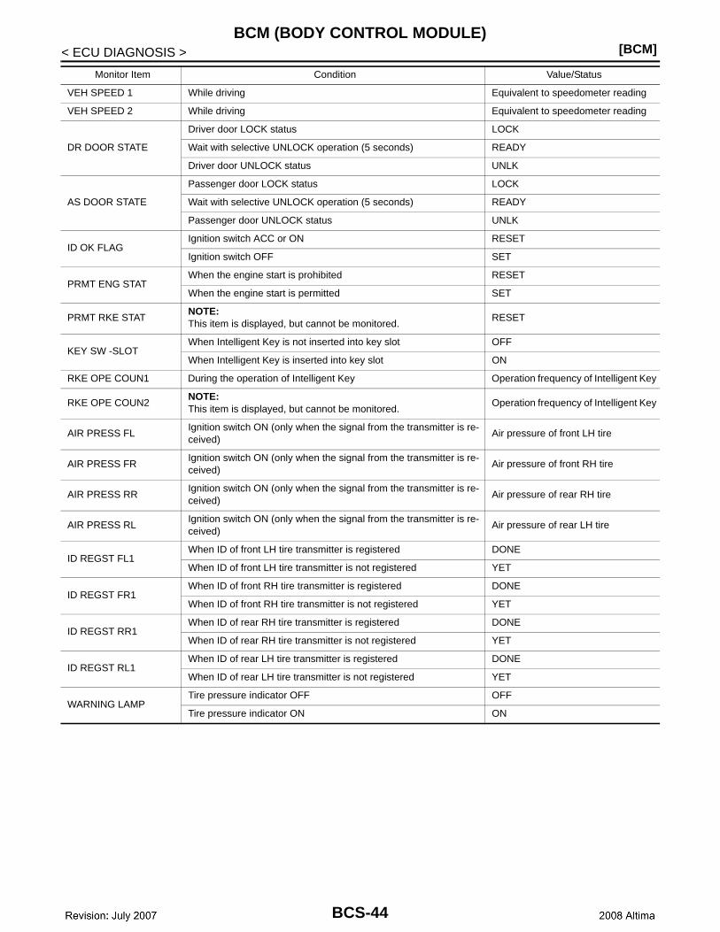
[BCM]BCM (BODY CONTROL MODULE)
< ECU DIAGNOSIS >
VEH SPEED 1 While driving Equivalent to speedometer reading
VEH SPEED 2 While driving Equivalent to speedometer reading
DR DOOR STATE
Driver door LOCK status LOCK
Wait with selective UNLOCK operation (5 seconds) READY
Driver door UNLOCK status UNLK
AS DOOR STATE
Passenger door LOCK status LOCK
Wait with selective UNLOCK operation (5 seconds) READY
Passenger door UNLOCK status UNLK
ID OK FLAGIgnition switch ACC or ON RESET
Ignition switch OFF SET
PRMT ENG STATWhen the engine start is prohibited RESET
When the engine start is permitted SET
PRMT RKE STATNOTE:This item is displayed, but cannot be monitored.
RESET
KEY SW -SLOTWhen Intelligent Key is not inserted into key slot OFF
When Intelligent Key is inserted into key slot ON
RKE OPE COUN1 During the operation of Intelligent Key Operation frequency of Intelligent Key
RKE OPE COUN2NOTE:This item is displayed, but cannot be monitored.
Operation frequency of Intelligent Key
AIR PRESS FLIgnition switch ON (only when the signal from the transmitter is re-ceived)
Air pressure of front LH tire
AIR PRESS FRIgnition switch ON (only when the signal from the transmitter is re-ceived)
Air pressure of front RH tire
AIR PRESS RRIgnition switch ON (only when the signal from the transmitter is re-ceived)
Air pressure of rear RH tire
AIR PRESS RLIgnition switch ON (only when the signal from the transmitter is re-ceived)
Air pressure of rear LH tire
ID REGST FL1When ID of front LH tire transmitter is registered DONE
When ID of front LH tire transmitter is not registered YET
ID REGST FR1When ID of front RH tire transmitter is registered DONE
When ID of front RH tire transmitter is not registered YET
ID REGST RR1When ID of rear RH tire transmitter is registered DONE
When ID of rear RH tire transmitter is not registered YET
ID REGST RL1When ID of rear LH tire transmitter is registered DONE
When ID of rear LH tire transmitter is not registered YET
WARNING LAMPTire pressure indicator OFF OFF
Tire pressure indicator ON ON
Monitor Item Condition Value/Status
BCS-44
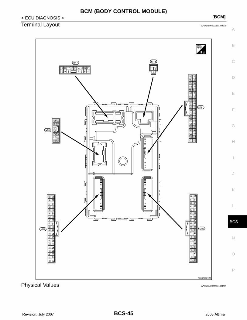
CS
BCM (BODY CONTROL MODULE)[BCM]
C
D
E
F
G
H
I
J
K
L
B
A
O
P
N
B
< ECU DIAGNOSIS >
Terminal Layout INFOID:0000000001344678
Physical Values INFOID:0000000001344679
ALMIA0127ZZ
BCS-45
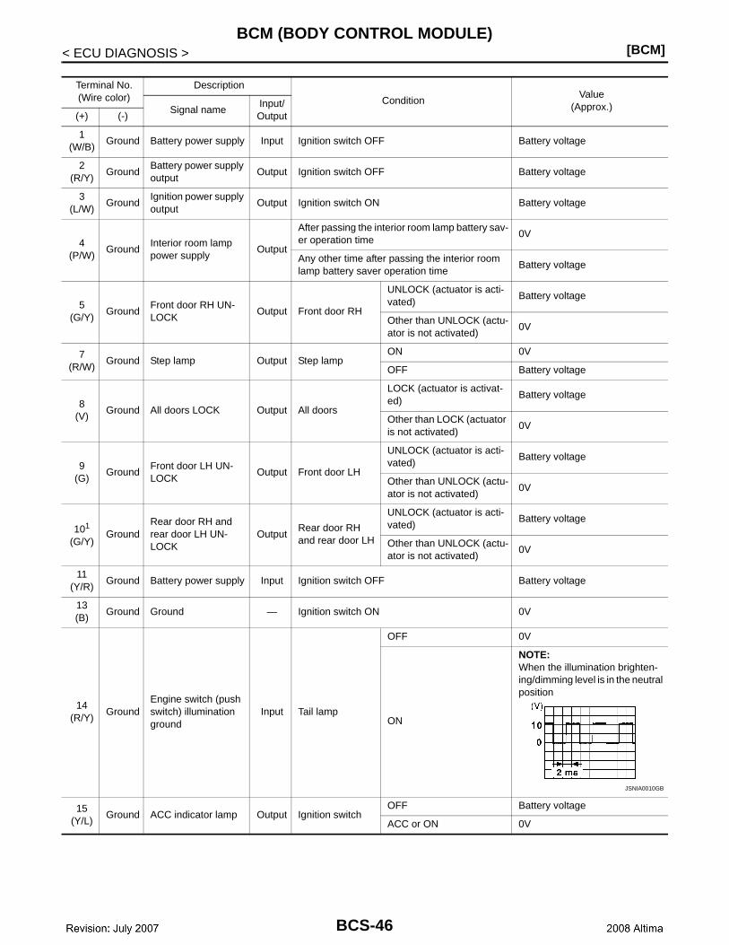
[BCM]BCM (BODY CONTROL MODULE)
< ECU DIAGNOSIS >
Terminal No.(Wire color)
Description
ConditionValue
(Approx.)Signal nameInput/ Output(+) (-)
1(W/B)
Ground Battery power supply Input Ignition switch OFF Battery voltage
2(R/Y)
GroundBattery power supply output
Output Ignition switch OFF Battery voltage
3(L/W)
GroundIgnition power supply output
Output Ignition switch ON Battery voltage
4(P/W)
GroundInterior room lamp power supply
Output
After passing the interior room lamp battery sav-er operation time
0V
Any other time after passing the interior room lamp battery saver operation time
Battery voltage
5(G/Y)
GroundFront door RH UN-LOCK
Output Front door RH
UNLOCK (actuator is acti-vated)
Battery voltage
Other than UNLOCK (actu-ator is not activated)
0V
7(R/W)
Ground Step lamp Output Step lampON 0V
OFF Battery voltage
8(V)
Ground All doors LOCK Output All doors
LOCK (actuator is activat-ed)
Battery voltage
Other than LOCK (actuator is not activated)
0V
9(G)
GroundFront door LH UN-LOCK
Output Front door LH
UNLOCK (actuator is acti-vated)
Battery voltage
Other than UNLOCK (actu-ator is not activated)
0V
101
(G/Y)Ground
Rear door RH and rear door LH UN-LOCK
OutputRear door RH and rear door LH
UNLOCK (actuator is acti-vated)
Battery voltage
Other than UNLOCK (actu-ator is not activated)
0V
11(Y/R)
Ground Battery power supply Input Ignition switch OFF Battery voltage
13(B)
Ground Ground — Ignition switch ON 0V
14(R/Y)
GroundEngine switch (push switch) illumination ground
Input Tail lamp
OFF 0V
ON
NOTE:When the illumination brighten-ing/dimming level is in the neutral position
15(Y/L)
Ground ACC indicator lamp Output Ignition switchOFF Battery voltage
ACC or ON 0V
JSNIA0010GB
BCS-46
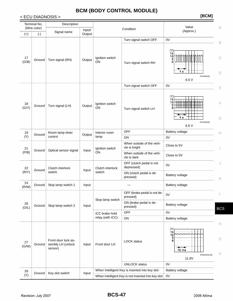
CS
BCM (BODY CONTROL MODULE)[BCM]
C
D
E
F
G
H
I
J
K
L
B
A
O
P
N
B
< ECU DIAGNOSIS >
17 (G/B)
Ground Turn signal (RH) OutputIgnition switch ON
Turn signal switch OFF 0V
Turn signal switch RH
6.5 V
18(G/Y)
Ground Turn signal (LH) OutputIgnition switch ON
Turn signal switch OFF 0V
Turn signal switch LH
6.5 V
19(Y)
GroundRoom lamp timer control
OutputInterior room lamp
OFF Battery voltage
ON 0V
21(P/B)
Ground Optical sensor signal InputIgnition switch ON
When outside of the vehi-cle is bright
Close to 5V
When outside of the vehi-cle is dark
Close to 0V
22(R/Y)
GroundClutch interlock switch
InputClutch interlock switch
OFF (clutch pedal is not depressed)
0V
ON (clutch pedal is de-pressed)
Battery voltage
24(R/W)
Ground Stop lamp switch 1 Input — Battery voltage
26(O/L)
Ground Stop lamp switch 2 Input
Stop lamp switch
OFF (brake pedal is not de-pressed)
0V
ON (brake pedal is de-pressed)
Battery voltage
ICC brake hold relay (with ICC)
OFF 0V
ON Battery voltage
27(G/W)
GroundFront door lock as-sembly LH (unlock sensor)
Input Front door LHLOCK status
11.8V
UNLOCK status 0V
29(Y)
Ground Key slot switch InputWhen Intelligent Key is inserted into key slot Battery voltage
When Intelligent Key is not inserted into key slot 0V
Terminal No.(Wire color)
Description
ConditionValue
(Approx.)Signal nameInput/ Output(+) (-)
PKID0926E
PKID0926E
JPMIA0011GB
BCS-47
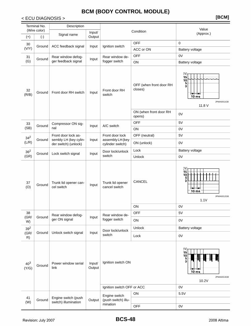
[BCM]BCM (BODY CONTROL MODULE)
< ECU DIAGNOSIS >
30(V/Y)
Ground ACC feedback signal Input Ignition switchOFF 0
ACC or ON Battery voltage
31(G)
GroundRear window defog-ger feedback signal
InputRear window de-fogger switch
OFF 0V
ON Battery voltage
32(R/B)
Ground Front door RH switch InputFront door RH switch
OFF (when front door RH closes)
11.8 V
ON (when front door RH opens)
0V
33(SB)
GroundCompressor ON sig-nal
Input A/C switchOFF 5V
ON 0V
342
(L/R)Ground
Front door lock as-sembly LH (key cylin-der switch) (unlock)
InputFront door lock assembly LH (key cylinder switch)
OFF (neutral) 5V
ON (unlock) 0V
362
(GR)Ground Lock switch signal Input
Door lock/unlock switch
Lock Battery voltage
Unlock 0V
37(O)
GroundTrunk lid opener can-cel switch
InputTrunk lid opener cancel switch
CANCEL
1.1V
ON 0V
38(GR/W)
GroundRear window defog-ger ON signal
InputRear window de-fogger switch
OFF 5V
ON 0V
392
(GR/R)
Ground Unlock switch signal InputDoor lock/unlock switch
Unlock Battery voltage
Lock 0V
403
(Y/G)Ground
Power window serial link
Input/Output
Ignition switch ON
10.2V
Ignition switch OFF or ACC 0V
41(W)
GroundEngine switch (push switch) illumination
OutputEngine switch (push switch) illu-mination
ON 5.5V
OFF 0V
Terminal No.(Wire color)
Description
ConditionValue
(Approx.)Signal nameInput/ Output(+) (-)
JPMIA0011GB
JPMIA0012GB
JPMIA0013GB
BCS-48

CS
BCM (BODY CONTROL MODULE)[BCM]
C
D
E
F
G
H
I
J
K
L
B
A
O
P
N
B
< ECU DIAGNOSIS >
42(R)
Ground LOCK indicator lamp OutputLOCK indicator lamp
ON 0V
OFF Battery voltage
45(P)
GroundReceiver & sensor ground
Input Ignition switch ON 0V
46(V/W)
GroundReceiver & sensor power supply output
Output Ignition switchOFF 0V
ACC or ON 5.0V
47(G/O)
GroundTire pressure receiv-er signal
Input/Output
Ignition switch ON
Standby state
When receiving the signal from the transmitter
48(R/G)
GroundSelector lever P/N position signal
Input Selector leverP or N position 12.0V
Except P and N positions 0V
49(L/O)
GroundSecurity indicator sig-nal
Output Security indicator
ON 0V
Blinking
11.3V
OFF Battery voltage
50(LG/B)
GroundCombination switch OUTPUT 5
Output
Combination switch(Wiper intermit-tent dial 4)
All switch OFF 0V
Lighting switch 1ST
10.7V
Lighting switch high-beam
Lighting switch 2ND
Turn signal switch RH
Terminal No.(Wire color)
Description
ConditionValue
(Approx.)Signal nameInput/ Output(+) (-)
OCC3881D
OCC3880D
JPMIA0014GB
JPMIA0031GB
BCS-49
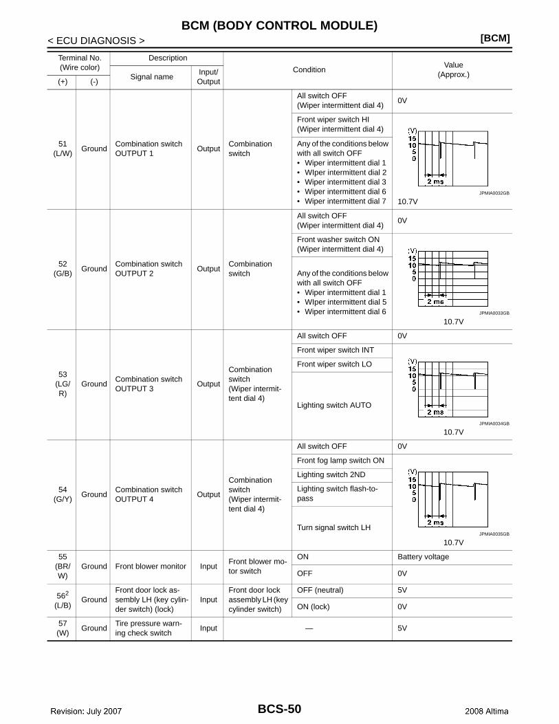
[BCM]BCM (BODY CONTROL MODULE)
< ECU DIAGNOSIS >
51(L/W)
GroundCombination switch OUTPUT 1
OutputCombination switch
All switch OFF(Wiper intermittent dial 4)
0V
Front wiper switch HI(Wiper intermittent dial 4)
10.7V
Any of the conditions below with all switch OFF• Wiper intermittent dial 1• WIper intermittent dial 2• Wiper intermittent dial 3• Wiper intermittent dial 6• Wiper intermittent dial 7
52(G/B)
GroundCombination switch OUTPUT 2
OutputCombination switch
All switch OFF(Wiper intermittent dial 4)
0V
Front washer switch ON(Wiper intermittent dial 4)
10.7V
Any of the conditions below with all switch OFF• Wiper intermittent dial 1• WIper intermittent dial 5• Wiper intermittent dial 6
53(LG/R)
GroundCombination switch OUTPUT 3
Output
Combination switch(Wiper intermit-tent dial 4)
All switch OFF 0V
Front wiper switch INT
10.7V
Front wiper switch LO
Lighting switch AUTO
54(G/Y)
GroundCombination switch OUTPUT 4
Output
Combination switch(Wiper intermit-tent dial 4)
All switch OFF 0V
Front fog lamp switch ON
10.7V
Lighting switch 2ND
Lighting switch flash-to-pass
Turn signal switch LH
55(BR/W)
Ground Front blower monitor InputFront blower mo-tor switch
ON Battery voltage
OFF 0V
562
(L/B)Ground
Front door lock as-sembly LH (key cylin-der switch) (lock)
InputFront door lock assembly LH (key cylinder switch)
OFF (neutral) 5V
ON (lock) 0V
57(W)
GroundTire pressure warn-ing check switch
Input — 5V
Terminal No.(Wire color)
Description
ConditionValue
(Approx.)Signal nameInput/ Output(+) (-)
JPMIA0032GB
JPMIA0033GB
JPMIA0034GB
JPMIA0035GB
BCS-50
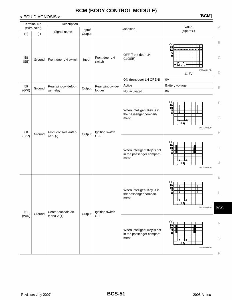
CS
BCM (BODY CONTROL MODULE)[BCM]
C
D
E
F
G
H
I
J
K
L
B
A
O
P
N
B
< ECU DIAGNOSIS >
58(SB)
Ground Front door LH switch InputFront door LH switch
OFF (front door LH CLOSE)
11.8V
ON (front door LH OPEN) 0V
59(G/R)
GroundRear window defog-ger relay
OutputRear window de-fogger
Active Battery voltage
Not activated 0V
60(B/R)
GroundFront console anten-na 2 (-)
OutputIgnition switch OFF
When Intelligent Key is in the passenger compart-ment
When Intelligent Key is not in the passenger compart-ment
61 (W/R)
GroundCenter console an-tenna 2 (+)
OutputIgnition switch OFF
When Intelligent Key is in the passenger compart-ment
When Intelligent Key is not in the passenger compart-ment
Terminal No.(Wire color)
Description
ConditionValue
(Approx.)Signal nameInput/ Output(+) (-)
JPMIA0011GB
JMKIA0062GB
JMKIA0063GB
JMKIA0062GB
JMKIA0063GB
BCS-51

[BCM]BCM (BODY CONTROL MODULE)
< ECU DIAGNOSIS >
62(B/Y)
GroundFront outside handle RH antenna (-)
Output
When the front door RH request switch is operat-ed with ignition switch OFF
When Intelligent Key is in the antenna detection area
When Intelligent Key is not in the antenna detection area
63(LG)
GroundFront outside handle RH antenna (+)
Output
When the front door RH request switch is operat-ed with ignition switch OFF
When Intelligent Key is in the antenna detection area
When Intelligent Key is not in the antenna detection area
64(V)
GroundFront outside handle LH antenna (-)
Output
When the front door LH request switch is operat-ed with ignition switch OFF
When Intelligent Key is in the antenna detection area
When Intelligent Key is not in the antenna detection area
Terminal No.(Wire color)
Description
ConditionValue
(Approx.)Signal nameInput/ Output(+) (-)
JMKIA0062GB
JMKIA0063GB
JMKIA0062GB
JMKIA0063GB
JMKIA0062GB
JMKIA0063GB
BCS-52

CS
BCM (BODY CONTROL MODULE)[BCM]
C
D
E
F
G
H
I
J
K
L
B
A
O
P
N
B
< ECU DIAGNOSIS >
65(P)
GroundFront outside handle LH antenna (+)
Output
When the front door LH request switch is operat-ed with ignition switch OFF
When Intelligent Key is in the antenna detection area
When Intelligent Key is not in the antenna detection area
66(R)
GroundInstrument panel an-tenna (-)
OutputIgnition switch OFF
When Intelligent Key is in the passenger compart-ment
When Intelligent Key is not in the passenger compart-ment
67(G)
GroundInstrument panel an-tenna (+)
OutputIgnition switch OFF
When Intelligent Key is in the passenger compart-ment
When Intelligent Key is not in the passenger compart-ment
Terminal No.(Wire color)
Description
ConditionValue
(Approx.)Signal nameInput/ Output(+) (-)
JMKIA0062GB
JMKIA0063GB
JMKIA0062GB
JMKIA0063GB
JMKIA0062GB
JMKIA0063GB
BCS-53

[BCM]BCM (BODY CONTROL MODULE)
< ECU DIAGNOSIS >
68(G/O)
GroundNATS antenna amp (built in key slot)
Input/Output
During waitingIgnition switch is pressed while inserting the Intelli-gent Key into the key slot.
Just after pressing ignition switch. Pointer of tester should move.
69(O)
GroundNATS antenna amp (built in key slot)
Input/Output
During waitingIgnition switch is pressed while inserting the Intelli-gent Key into the key slot.
Just after pressing ignition switch. Pointer of tester should move.
70(R/B)
GroundIgnition relay-2 con-trol
Output Ignition switchOFF or ACC 0V
ON Battery voltage
71(L/O)
GroundRemote keyless entry receiver signal
Input/Output
During waiting
When operating either button on Intelligent Key
75(R/Y)
GroundCombination switch INPUT 5
InputCombination switch
All switch OFF(Wiper intermittent dial 4)
1.4V
Front fog lamp switch ON(Wiper intermittent dial 4)
1.3V
Any of the conditions below with all switch OFF• Wiper intermittent dial 1• Wiper intermittent dial 2• Wiper intermittent dial 6• Wiper intermittent dial 7
1.3V
Terminal No.(Wire color)
Description
ConditionValue
(Approx.)Signal nameInput/ Output(+) (-)
JMKIA0064GB
JMKIA0065GB
JPMIA0041GB
JPMIA0037GB
JPMIA0040GB
BCS-54

CS
BCM (BODY CONTROL MODULE)[BCM]
C
D
E
F
G
H
I
J
K
L
B
A
O
P
N
B
< ECU DIAGNOSIS >
76(R/G)
GroundCombination switch INPUT 3
InputCombination switch
All switch OFF(Wiper intermittent dial 4)
1.4V
Lighting switch high-beam(Wiper intermittent dial 4)
1.3V
Lighting switch 2ND(Wiper intermittent dial 4)
1.3V
Any of the conditions below with all switch OFF• Wiper intermittent dial 1• Wiper intermittent dial 2• Wiper intermittent dial 3
1.3V
77(BR)
GroundEngine switch (push switch)
InputEngine switch (push switch)
Pressed 0V
Not pressed Battery voltage
78(P)
Ground CAN-LInput/ Output
— —
79(L)
Ground CAN-HInput/ Output
— —
80(R/L)
Ground Key slot illumination OutputKey slot illumina-tion
OFF 0V
Blinking
6.5V
ON Battery voltage
Terminal No.(Wire color)
Description
ConditionValue
(Approx.)Signal nameInput/ Output(+) (-)
JPMIA0041GB
JPMIA0036GB
JPMIA0037GB
JPMIA0040GB
JPMIA0015GB
BCS-55

[BCM]BCM (BODY CONTROL MODULE)
< ECU DIAGNOSIS >
81(LG)
Ground ON indicator lamp Output Ignition switchOFF or ACC 0V
ON Battery voltage
83(L)
Ground ACC relay control Output Ignition switchOFF 0V
ACC or ON Battery voltage
84(Y/R)
Ground A/T device Output — Battery voltage
85(L/O)
GroundElectronic steering column lock condition No. 1
InputElectronic steer-ing column lock
Lock status 0V
Unlock status Battery voltage
86(G/R)
GroundElectronic steering column lock condition No. 2
InputElectronic steer-ing column lock
Lock status Battery voltage
Unlock status 0V
87(G/B)
GroundSelector lever P posi-tion switch
Input Selector leverP position 0V
Any position other than P Battery voltage
88(P/L)
GroundFront door RH re-quest switch
InputFront door RH re-quest switch
ON (pressed) 0V
OFF (not pressed)
1.0V
89(B/W)
GroundFront door LH re-quest switch
InputFront door LH re-quest switch
ON (pressed) 0V
OFF (not pressed)
1.0V
90(Y)
GroundBlower fan motor re-lay control
Output Ignition switchOFF or ACC 0V
ON Battery voltage
91(L/R)
GroundRemote keyless entry receiver power sup-ply
Output Ignition switch OFF Battery voltage
94(G/Y)
GroundSteering wheel lock unit power supply
Output Ignition switchOFF or ACC Battery voltage
ON 0V
Terminal No.(Wire color)
Description
ConditionValue
(Approx.)Signal nameInput/ Output(+) (-)
JPMIA0016GB
JPMIA0016GB
BCS-56
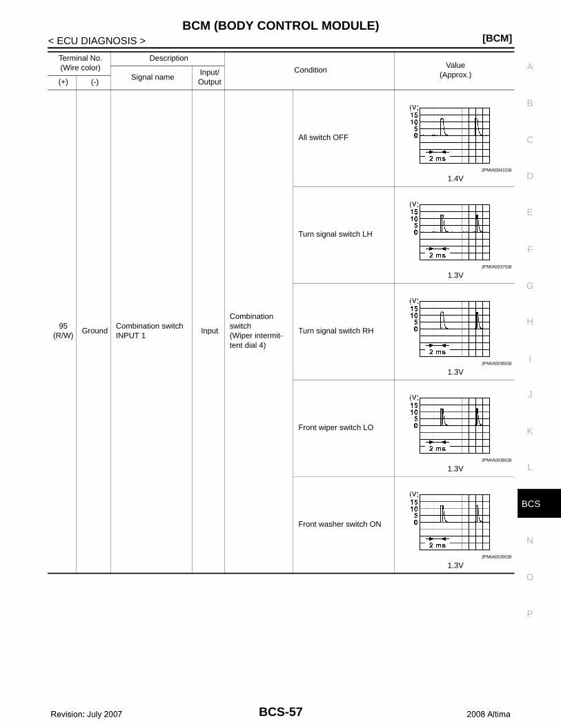
CS
BCM (BODY CONTROL MODULE)[BCM]
C
D
E
F
G
H
I
J
K
L
B
A
O
P
N
B
< ECU DIAGNOSIS >
95(R/W)
GroundCombination switch INPUT 1
Input
Combination switch(Wiper intermit-tent dial 4)
All switch OFF
1.4V
Turn signal switch LH
1.3V
Turn signal switch RH
1.3V
Front wiper switch LO
1.3V
Front washer switch ON
1.3V
Terminal No.(Wire color)
Description
ConditionValue
(Approx.)Signal nameInput/ Output(+) (-)
JPMIA0041GB
JPMIA0037GB
JPMIA0036GB
JPMIA0038GB
JPMIA0039GB
BCS-57

[BCM]BCM (BODY CONTROL MODULE)
< ECU DIAGNOSIS >
96(P/B)
GroundCombination switch INPUT 4
InputCombination switch
All switch OFF(Wiper intermittent dial 4)
1.4V
Lighting switch AUTO(Wiper intermittent dial 4)
1.3V
Lighting switch 1ST(Wiper intermittent dial 4)
1.3V
Any of the conditions below with all switch OFF• Wiper intermittent dial 1• Wiper intermittent dial 5• Wiper intermittent dial 6
1.3V
Terminal No.(Wire color)
Description
ConditionValue
(Approx.)Signal nameInput/ Output(+) (-)
JPMIA0041GB
JPMIA0038GB
JPMIA0036GB
JPMIA0039GB
BCS-58

CS
BCM (BODY CONTROL MODULE)[BCM]
C
D
E
F
G
H
I
J
K
L
B
A
O
P
N
B
< ECU DIAGNOSIS >
97(R/B)
GroundCombination switch INPUT 2
Input
Combination switch(Wiper intermit-tent dial 4)
All switch OFF
1.4V
Lighting switch flash-to-pass
1.3V
Lighting switch 2ND
1.3V
Front wiper switch INT
1.3V
Front wiper switch HI
1.3V
98(G/O)
Ground Hazard switch Input Hazard switch
Pressed 0 V
Not pressed
1.1V
Terminal No.(Wire color)
Description
ConditionValue
(Approx.)Signal nameInput/ Output(+) (-)
JPMIA0041GB
JPMIA0037GB
JPMIA0036GB
JPMIA0038GB
JPMIA0040GB
JPMIA0012GB
BCS-59

[BCM]BCM (BODY CONTROL MODULE)
< ECU DIAGNOSIS >
99(L/Y)
GroundElectronic steering column lock unit com-munication
Input/Output
Electronic steer-ing column lock
LOCK status Battery voltage
LOCK or UNLOCK
For 15 seconds after UN-LOCK
Battery voltage
15 seconds or later after UNLOCK
0V
103(V)
Ground Trunk lid opening. Output Trunk lid
Open (trunk lid opener ac-tuator is activated)
Battery voltage
Close (trunk lid opener ac-tuator is not activated)
0V
110(V/W)
Ground Trunk room lamp Output Trunk room lampON 0V
OFF Battery voltage
114(B)
GroundTrunk room antenna 1 (-)
OutputIgnition switch OFF
When Intelligent Key is in the passenger compart-ment
When Intelligent Key is not in the passenger compart-ment
Terminal No.(Wire color)
Description
ConditionValue
(Approx.)Signal nameInput/ Output(+) (-)
JMKIA0066GB
JMKIA0062GB
JMKIA0063GB
BCS-60
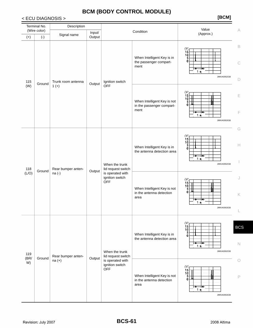
CS
BCM (BODY CONTROL MODULE)[BCM]
C
D
E
F
G
H
I
J
K
L
B
A
O
P
N
B
< ECU DIAGNOSIS >
115(W)
GroundTrunk room antenna 1 (+)
OutputIgnition switch OFF
When Intelligent Key is in the passenger compart-ment
When Intelligent Key is not in the passenger compart-ment
118(L/O)
GroundRear bumper anten-na (-)
Output
When the trunk lid request switch is operated with ignition switch OFF
When Intelligent Key is in the antenna detection area
When Intelligent Key is not in the antenna detection area
119(BR/W)
GroundRear bumper anten-na (+)
Output
When the trunk lid request switch is operated with ignition switch OFF
When Intelligent Key is in the antenna detection area
When Intelligent Key is not in the antenna detection area
Terminal No.(Wire color)
Description
ConditionValue
(Approx.)Signal nameInput/ Output(+) (-)
JMKIA0062GB
JMKIA0063GB
JMKIA0062GB
JMKIA0063GB
JMKIA0062GB
JMKIA0063GB
BCS-61
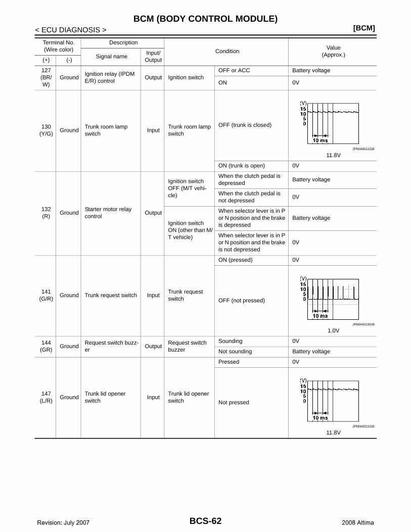
[BCM]BCM (BODY CONTROL MODULE)
< ECU DIAGNOSIS >
127(BR/W)
GroundIgnition relay (IPDM E/R) control
Output Ignition switchOFF or ACC Battery voltage
ON 0V
130(Y/G)
GroundTrunk room lamp switch
InputTrunk room lamp switch
OFF (trunk is closed)
11.8V
ON (trunk is open) 0V
132(R)
GroundStarter motor relay control
Output
Ignition switch OFF (M/T vehi-cle)
When the clutch pedal is depressed
Battery voltage
When the clutch pedal is not depressed
0V
Ignition switch ON (other than M/T vehicle)
When selector lever is in P or N position and the brake is depressed
Battery voltage
When selector lever is in P or N position and the brake is not depressed
0V
141(G/R)
Ground Trunk request switch InputTrunk request switch
ON (pressed) 0V
OFF (not pressed)
1.0V
144(GR)
GroundRequest switch buzz-er
OutputRequest switch buzzer
Sounding 0V
Not sounding Battery voltage
147(L/R)
GroundTrunk lid opener switch
InputTrunk lid opener switch
Pressed 0V
Not pressed
11.8V
Terminal No.(Wire color)
Description
ConditionValue
(Approx.)Signal nameInput/ Output(+) (-)
JPMIA0011GB
JPMIA0016GB
JPMIA0011GB
BCS-62

CS
BCM (BODY CONTROL MODULE)[BCM]
C
D
E
F
G
H
I
J
K
L
B
A
O
P
N
B
< ECU DIAGNOSIS >
1: Sedan only
2: With LH front window anti-pinch
3: With LH and RH front window anti-pinch
1481
(R/W)Ground Rear door RH switch Input
Rear door RH switch
OFF (when rear door RH closes)
11.8V
ON (when rear door RH opens)
0V
1491
(R/B)Ground Rear door LH switch Input
Rear door LH switch
OFF (when rear door LH closes)
11.8V
ON (when rear door LH opens)
0V
Terminal No.(Wire color)
Description
ConditionValue
(Approx.)Signal nameInput/ Output(+) (-)
JPMIA0011GB
JPMIA0011GB
BCS-63
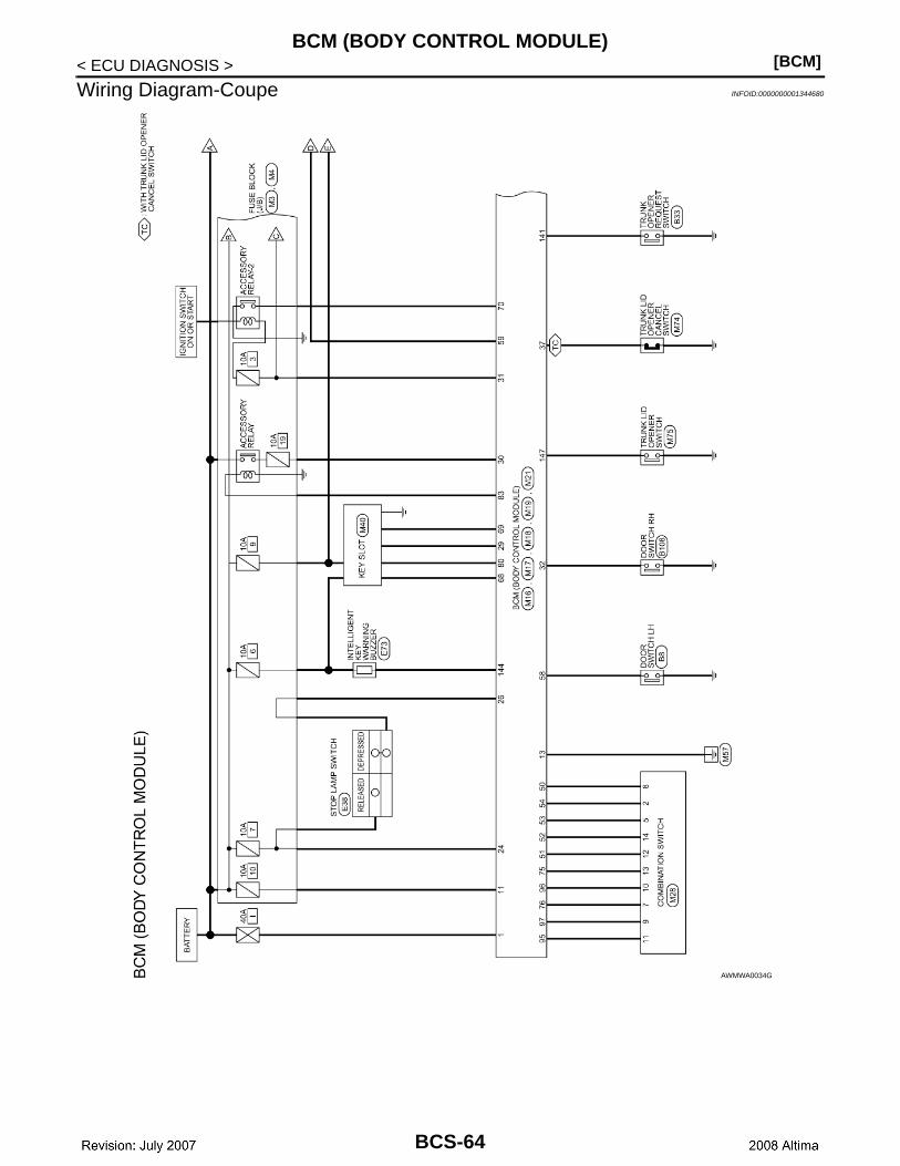
[BCM]BCM (BODY CONTROL MODULE)
< ECU DIAGNOSIS >
Wiring Diagram-Coupe INFOID:0000000001344680
AWMWA0034GB
BCS-64
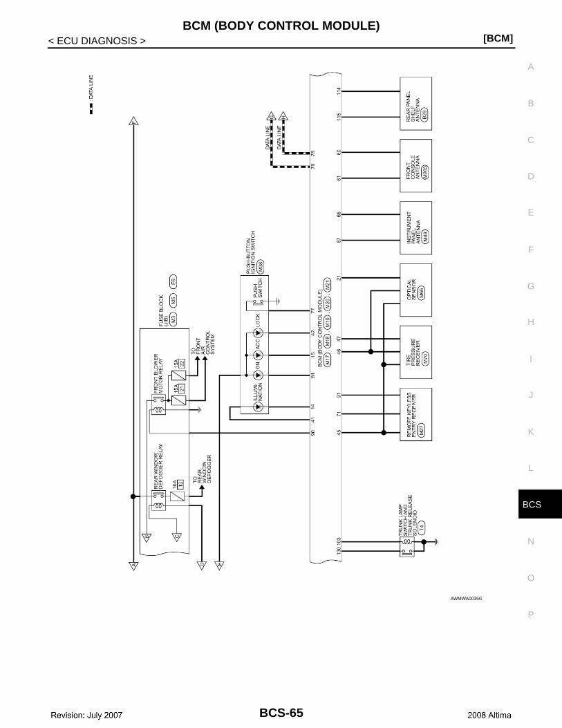
CS
BCM (BODY CONTROL MODULE)[BCM]
C
D
E
F
G
H
I
J
K
L
B
A
O
P
N
B
< ECU DIAGNOSIS >
AWMWA0035GB
BCS-65
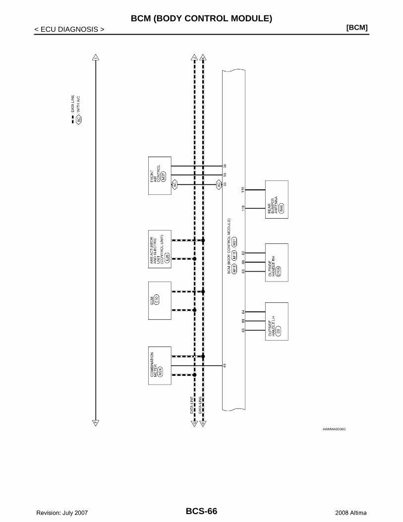
[BCM]BCM (BODY CONTROL MODULE)
< ECU DIAGNOSIS >
AWMWA0036GB
BCS-66
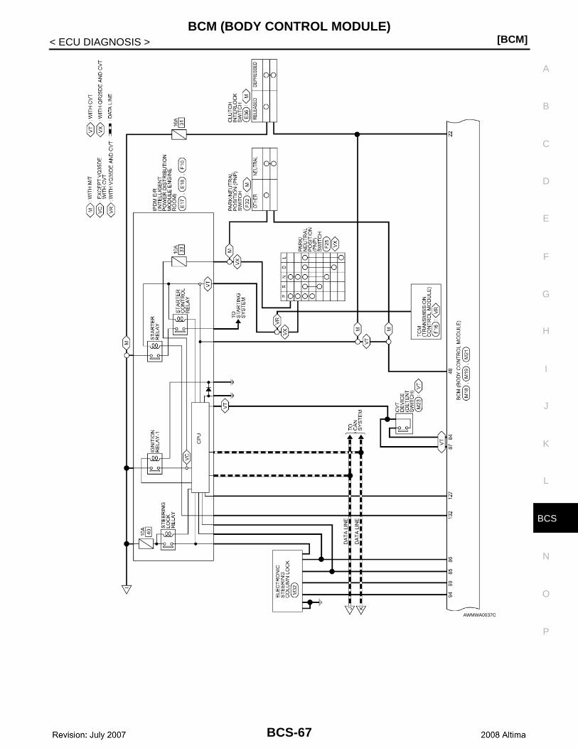
CS
BCM (BODY CONTROL MODULE)[BCM]
C
D
E
F
G
H
I
J
K
L
B
A
O
P
N
B
< ECU DIAGNOSIS >
AWMWA0037GB
BCS-67
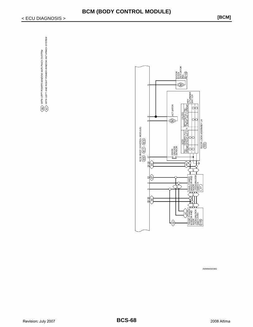
[BCM]BCM (BODY CONTROL MODULE)
< ECU DIAGNOSIS >
AWMWA0038GB
BCS-68

CS
BCM (BODY CONTROL MODULE)[BCM]
C
D
E
F
G
H
I
J
K
L
B
A
O
P
N
B
< ECU DIAGNOSIS >
AWMWA0045GB
BCS-69
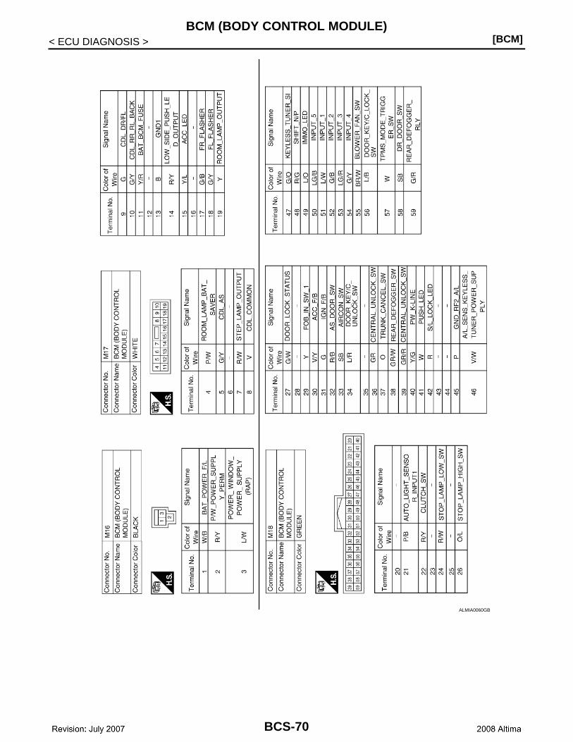
[BCM]BCM (BODY CONTROL MODULE)
< ECU DIAGNOSIS >
ALMIA0060GB
BCS-70
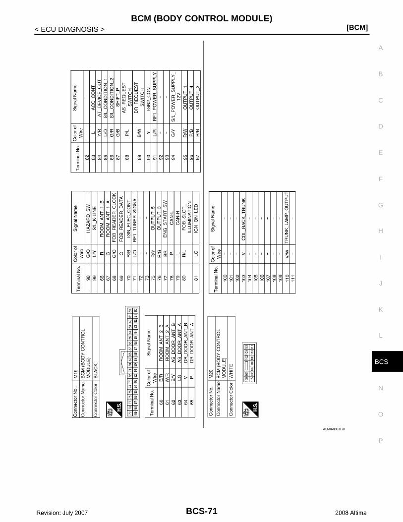
CS
BCM (BODY CONTROL MODULE)[BCM]
C
D
E
F
G
H
I
J
K
L
B
A
O
P
N
B
< ECU DIAGNOSIS >
ALMIA0061GB
BCS-71

[BCM]BCM (BODY CONTROL MODULE)
< ECU DIAGNOSIS >
AWMIA0077GB
BCS-72
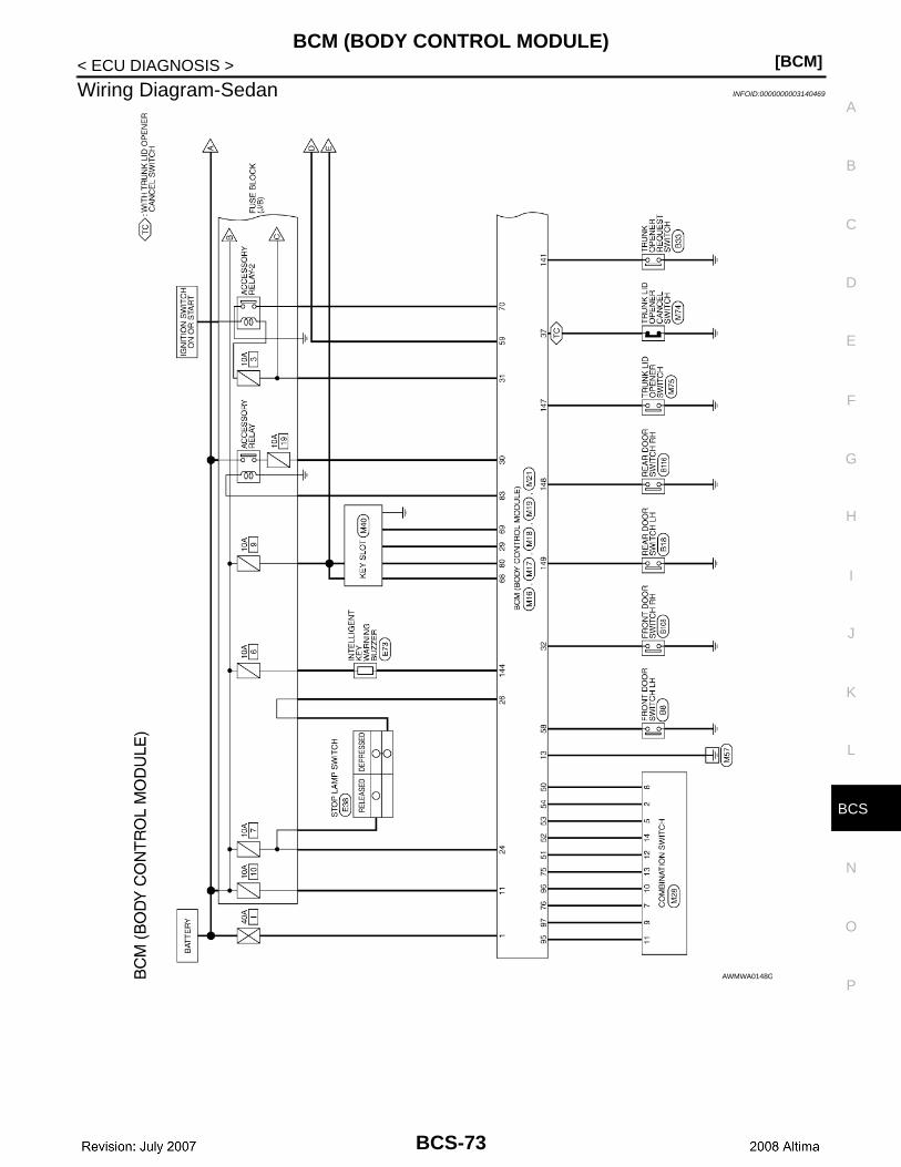
CS
BCM (BODY CONTROL MODULE)[BCM]
C
D
E
F
G
H
I
J
K
L
B
A
O
P
N
B
< ECU DIAGNOSIS >
Wiring Diagram-Sedan INFOID:0000000003140469
AWMWA0148GB
BCS-73

[BCM]BCM (BODY CONTROL MODULE)
< ECU DIAGNOSIS >
AWMWA0149GB
BCS-74

CS
BCM (BODY CONTROL MODULE)[BCM]
C
D
E
F
G
H
I
J
K
L
B
A
O
P
N
B
< ECU DIAGNOSIS >
AWMWA0150GB
BCS-75

[BCM]BCM (BODY CONTROL MODULE)
< ECU DIAGNOSIS >
AWMWA0151GB
BCS-76

CS
BCM (BODY CONTROL MODULE)[BCM]
C
D
E
F
G
H
I
J
K
L
B
A
O
P
N
B
< ECU DIAGNOSIS >
ALMWA0025GB
BCS-77
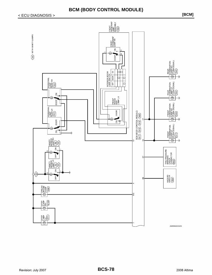
[BCM]BCM (BODY CONTROL MODULE)
< ECU DIAGNOSIS >
AWMWA0152GB
BCS-78
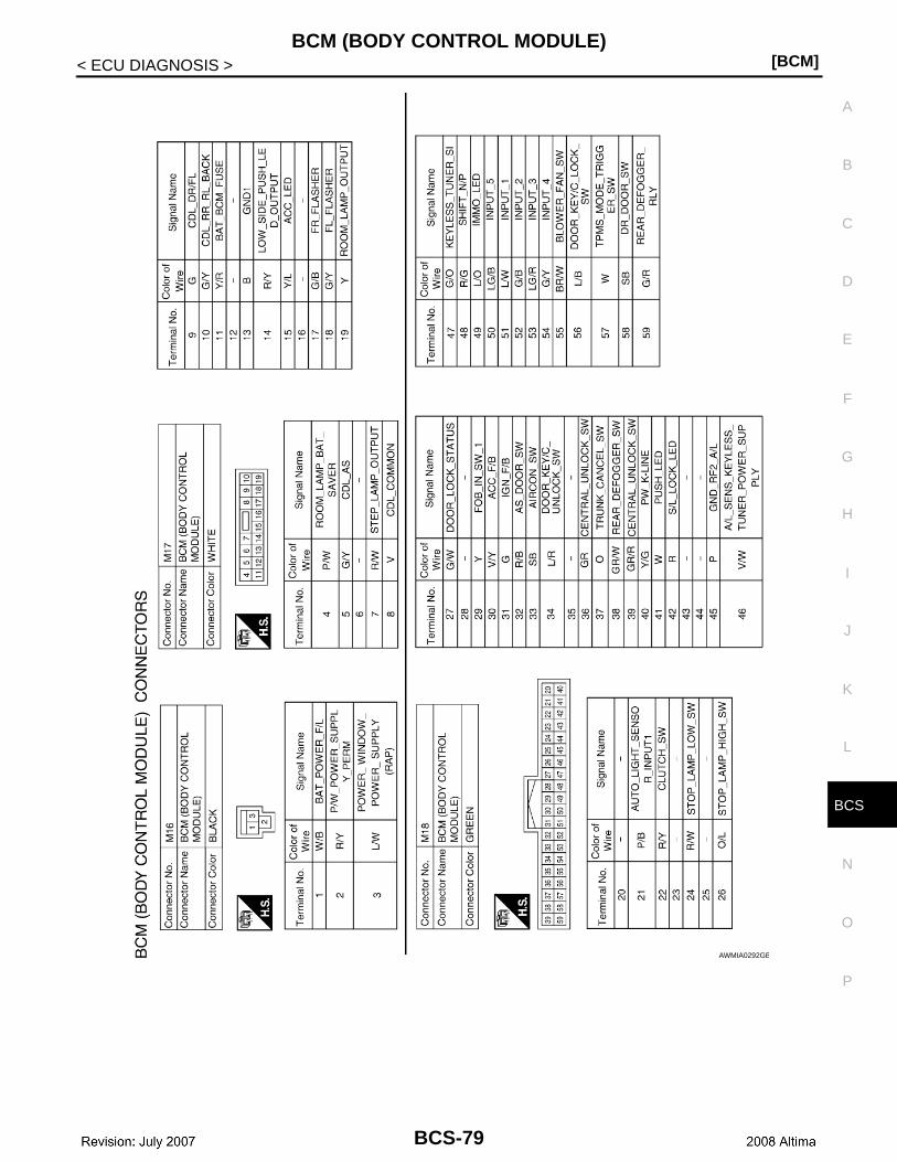
CS
BCM (BODY CONTROL MODULE)[BCM]
C
D
E
F
G
H
I
J
K
L
B
A
O
P
N
B
< ECU DIAGNOSIS >
AWMIA0292GB
BCS-79
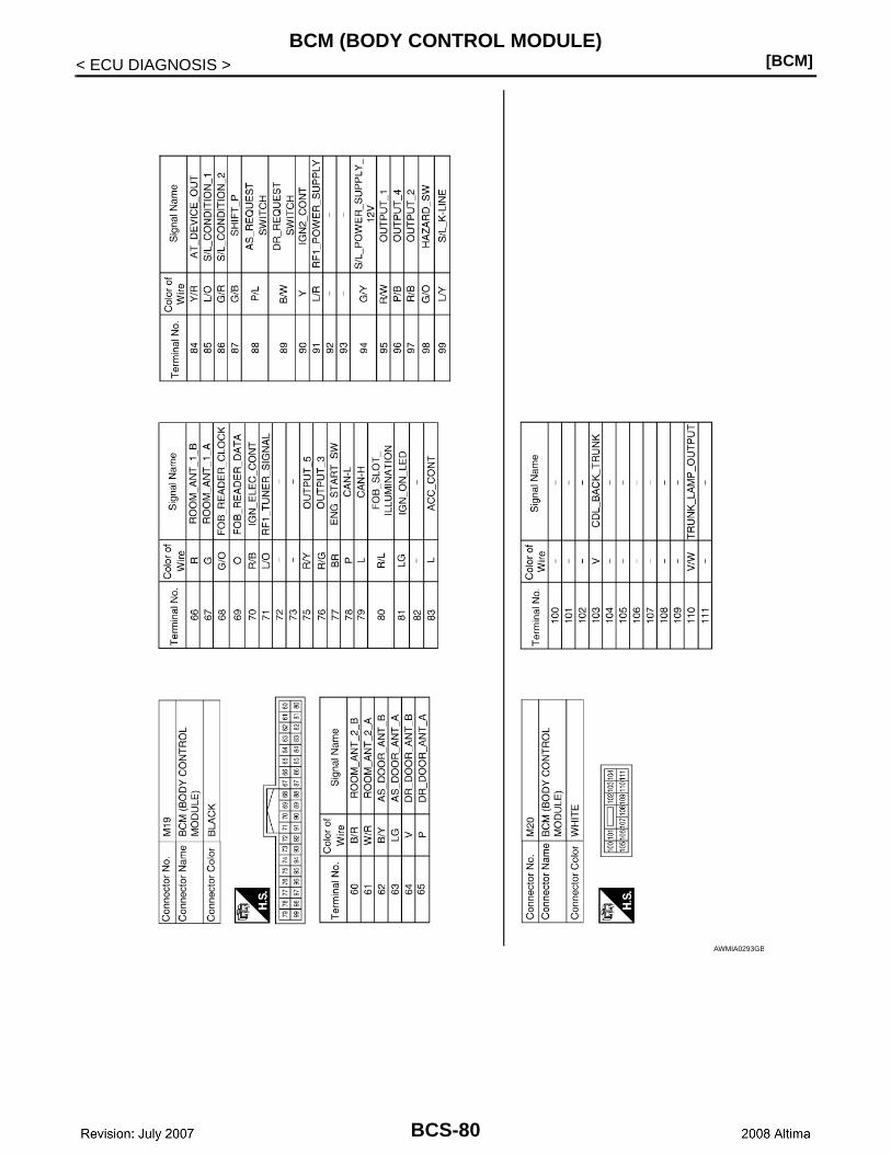
[BCM]BCM (BODY CONTROL MODULE)
< ECU DIAGNOSIS >
AWMIA0293GB
BCS-80
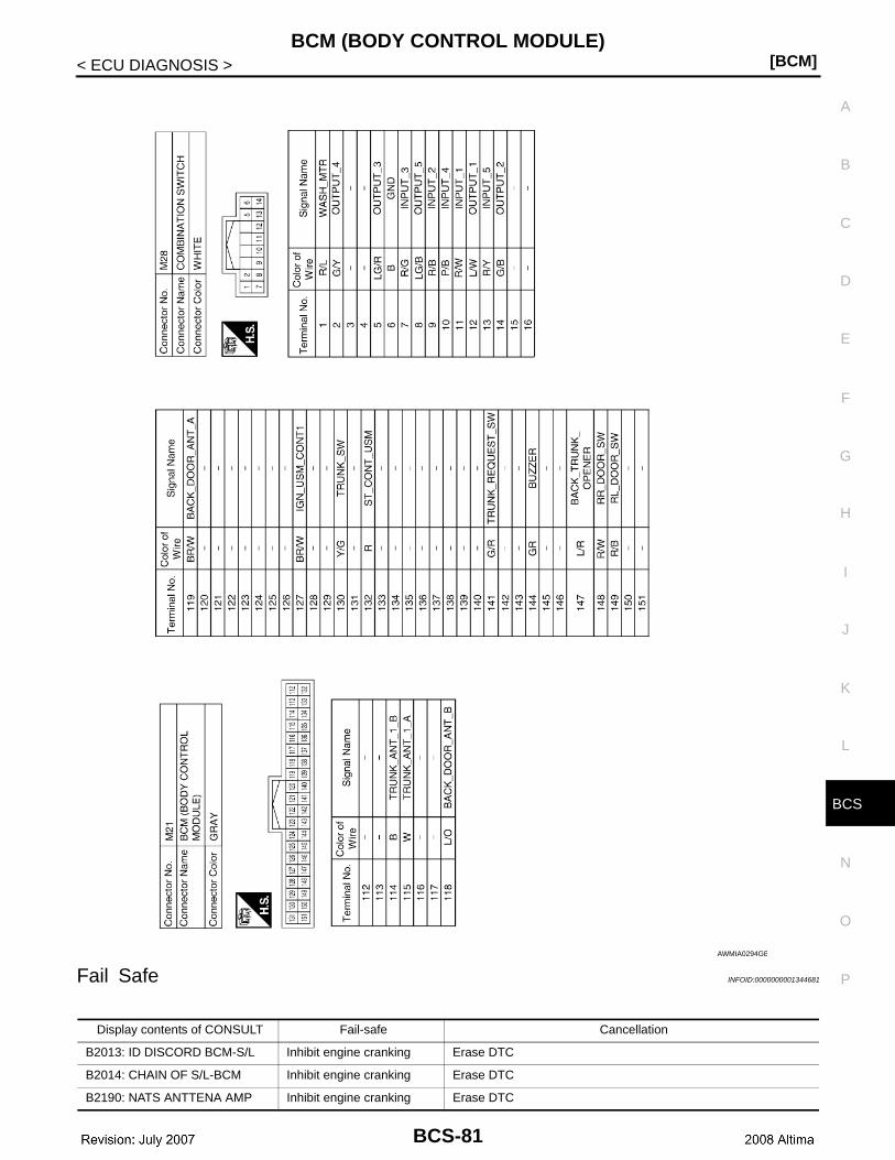
CS
BCM (BODY CONTROL MODULE)[BCM]
C
D
E
F
G
H
I
J
K
L
B
A
O
P
N
B
< ECU DIAGNOSIS >
Fail Safe INFOID:0000000001344681
AWMIA0294GB
Display contents of CONSULT Fail-safe Cancellation
B2013: ID DISCORD BCM-S/L Inhibit engine cranking Erase DTC
B2014: CHAIN OF S/L-BCM Inhibit engine cranking Erase DTC
B2190: NATS ANTTENA AMP Inhibit engine cranking Erase DTC
BCS-81
[BCM]BCM (BODY CONTROL MODULE)
< ECU DIAGNOSIS >
B2191: DIFFERENCE OF KEY Inhibit engine cranking Erase DTC
B2192: ID DISCORD BCM-ECM Inhibit engine cranking Erase DTC
B2193: CHAIN OF BCM-ECM Inhibit engine cranking Erase DTC
B2195: ANTI-SCANNING Inhibit engine cranking Erase DTC
B2557: VEHICLE SPEEDInhibit electronic steering column lock
When normal vehicle speed signals have been received from ABS actuator and electric unit (control unit) for 500 ms
B2560: STARTER CONT RELAY Inhibit engine cranking
500 ms after the following CAN signal communication status has become consistent• Starter control relay signal• Starter relay status signal
B2562: LO VOLTAGE• Inhibit engine cranking• Inhibit electronic steering
column lock100 ms after the power supply voltage increases to more than 8.8 V
B2563: HI VOLTAGE• Inhibit engine cranking• Inhibit electronic steering
column lock500 ms after the power supply voltage decreases to less than 18 V
B2601: SHIFT POSITIONInhibit electronic steering column lock
500 ms after the following signal reception status becomes consis-tent• Selector lever P position switch signal• P range signal (CAN)
B2602: SHIFT POSITIONInhibit electronic steering column lock
5 seconds after the following BCM recognition conditions are ful-filled• Ignition switch is in the ON position• Selector lever P position switch signal: Except P position (battery
voltage)• Vehicle speed: 4 /h or more
B2603: SHIFT POSI STATUSInhibit electronic steering column lock
500 ms after the following BCM recognition conditions are fulfilled• Ignition switch is in the ON position• Selector lever P position switch signal: Except P position (battery
voltage)• Selector lever P/N position signal: Except P and N positions (0 V)
B2604: PNP SWInhibit electronic steering column lock
500 ms after any of the following BCM recognition conditions is ful-filled• Status 1- Ignition switch is in the ON position- Selector lever P/N position signal: P and N position (battery volt-
age)- P range signal or N range signal (CAN): ON• Status 2- Ignition switch is in the ON position- Selector lever P/N position signal: Except P and N positions (0 V)- P range signal and N range signal (CAN): OFF
B2605: PNP SWInhibit electronic steering column lock
500 ms after any of the following BCM recognition conditions is ful-filled• Ignition switch is in the ON position- Power position: IGN- Selector lever P/N position signal: Except P and N positions (0 V)- Interlock/PNP switch signal (CAN): OFF• Status 2- Ignition switch is in the ON position- Selector lever P/N position signal: P or N position (battery volt-
age)- PNP switch signal (CAN): ON
B2606: S/L RELAY Inhibit engine cranking
500 ms after the following CAN signal communication status has become consistent• Electronic steering column lock relay signal (Request signal)• Electronic steering column lock relay signal (Condition signal)
Display contents of CONSULT Fail-safe Cancellation
BCS-82

CS
BCM (BODY CONTROL MODULE)[BCM]
C
D
E
F
G
H
I
J
K
L
B
A
O
P
N
B
< ECU DIAGNOSIS >
DTC Inspection Priority Chart INFOID:0000000001344682
If some DTCs are displayed at the same time, perform inspections one by one based on the following prioritychart.
B2607: S/L RELAY Inhibit engine cranking
500 ms after the following CAN signal communication status has become consistent• Electronic steering column lock relay signal (Request signal)• Electronic steering column lock relay signal (Condition signal)
B2608: STARTER RELAY Inhibit engine cranking
500 ms after the following signal communication status becomes consistent• Starter motor relay control signal• Starter relay status signal (CAN)
B2609: S/L STATUS• Inhibit engine cranking• Inhibit electronic steering
column lock
When the following electronic steering column lock conditions agree• BCM electronic steering column lock control status• Electronic steering column lock condition No. 1 signal status• Electronic steering column lock condition No. 2 signal status
B260A: IGNITION RELAY Inhibit engine cranking
500 ms after the following conditions are fulfilled• IGN relay (IPDM E/R) control signal: OFF (Battery voltage)• Ignition ON signal (CAN to IPDM E/R): OFF (Request signal)• Ignition ON signal (CAN from IPDM E/R): OFF (Condition signal)
B260F: ENG STATE SIG LOSTMaintains the power supply position attained at the time of DTC detection
When any of the following conditions is fulfilled• Power position changes to ACC• Receives engine status signal (CAN)
B2612: S/L STATUS• Inhibit engine cranking• Inhibit electronic steering
column lock
When any of the following conditions is fulfilled• Electronic steering column lock unit status signal (CAN) is re-
ceived normally• The BCM electronic steering column lock control status matches
the electronic steering column lock status recognized by the electronic steering column lock unit status signal (CAN from IPDM E/R)
B2617: STARTER RELAY CIRC Inhibit engine cranking1 second after the starter motor relay control inside BCM becomes normal
B2618: BCM Inhibit engine cranking1 second after the ignition relay (IPDM E/R) control inside BCM be-comes normal
B2619: BCM Inhibit engine cranking1 second after the electronic steering column lock unit power sup-ply output control inside BCM becomes normal
B261E: VEHICLE TYPE Inhibit engine cranking BCM initialization
B26E1: ENG STATE NO RECIV Inhibit engine crankingWhen any of the following conditions is fulfilled• Power position changes to ACC• Receives engine status signal (CAN)
Display contents of CONSULT Fail-safe Cancellation
Priority DTC
1• B2562: LOW VOLTAGE• B2563: HI VOLTAGE• B261E: VEHICLE TYPE
2• U1000: CAN COMM CIRCUIT• U1010: CONTROL UNIT (CAN)
3
• B2190: NATS ANTTENA AMP• B2191: DIFFERENCE OF KEY• B2192: ID DISCORD BCM-ECM• B2193: CHAIN OF BCM-ECM
BCS-83
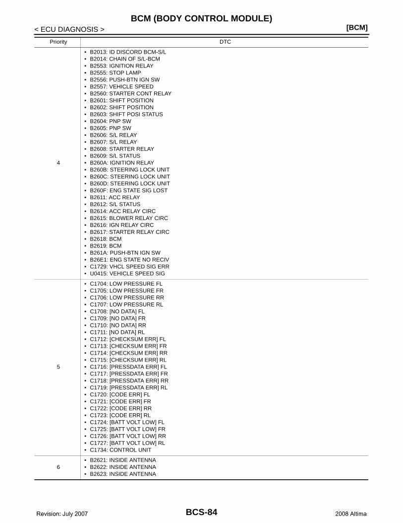
[BCM]BCM (BODY CONTROL MODULE)
< ECU DIAGNOSIS >
4
• B2013: ID DISCORD BCM-S/L• B2014: CHAIN OF S/L-BCM• B2553: IGNITION RELAY• B2555: STOP LAMP • B2556: PUSH-BTN IGN SW• B2557: VEHICLE SPEED• B2560: STARTER CONT RELAY• B2601: SHIFT POSITION• B2602: SHIFT POSITION• B2603: SHIFT POSI STATUS• B2604: PNP SW• B2605: PNP SW• B2606: S/L RELAY• B2607: S/L RELAY• B2608: STARTER RELAY• B2609: S/L STATUS• B260A: IGNITION RELAY• B260B: STEERING LOCK UNIT• B260C: STEERING LOCK UNIT• B260D: STEERING LOCK UNIT• B260F: ENG STATE SIG LOST• B2611: ACC RELAY• B2612: S/L STATUS• B2614: ACC RELAY CIRC• B2615: BLOWER RELAY CIRC• B2616: IGN RELAY CIRC• B2617: STARTER RELAY CIRC• B2618: BCM• B2619: BCM• B261A: PUSH-BTN IGN SW• B26E1: ENG STATE NO RECIV• C1729: VHCL SPEED SIG ERR• U0415: VEHICLE SPEED SIG
5
• C1704: LOW PRESSURE FL• C1705: LOW PRESSURE FR• C1706: LOW PRESSURE RR• C1707: LOW PRESSURE RL• C1708: [NO DATA] FL• C1709: [NO DATA] FR• C1710: [NO DATA] RR• C1711: [NO DATA] RL• C1712: [CHECKSUM ERR] FL• C1713: [CHECKSUM ERR] FR• C1714: [CHECKSUM ERR] RR• C1715: [CHECKSUM ERR] RL• C1716: [PRESSDATA ERR] FL• C1717: [PRESSDATA ERR] FR• C1718: [PRESSDATA ERR] RR• C1719: [PRESSDATA ERR] RL• C1720: [CODE ERR] FL• C1721: [CODE ERR] FR• C1722: [CODE ERR] RR• C1723: [CODE ERR] RL• C1724: [BATT VOLT LOW] FL• C1725: [BATT VOLT LOW] FR• C1726: [BATT VOLT LOW] RR• C1727: [BATT VOLT LOW] RL• C1734: CONTROL UNIT
6• B2621: INSIDE ANTENNA • B2622: INSIDE ANTENNA • B2623: INSIDE ANTENNA
Priority DTC
BCS-84
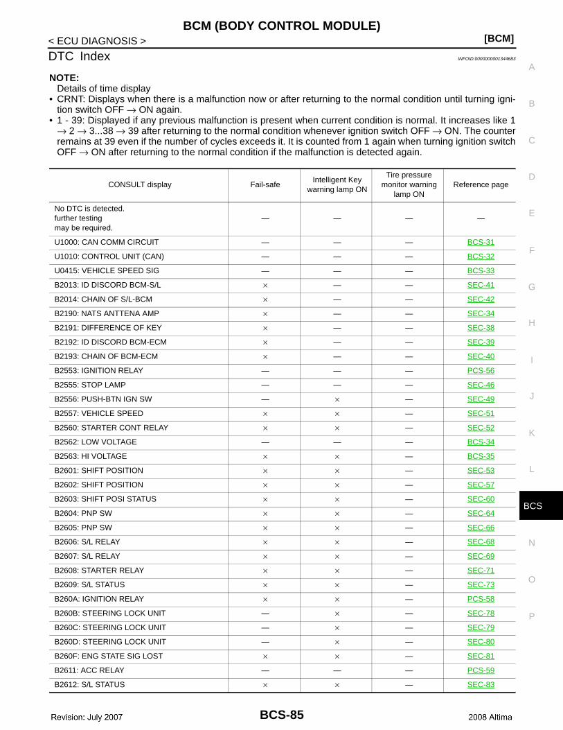
CS
BCM (BODY CONTROL MODULE)[BCM]
C
D
E
F
G
H
I
J
K
L
B
A
O
P
N
B
< ECU DIAGNOSIS >
DTC Index INFOID:0000000001344683
NOTE:Details of time display
• CRNT: Displays when there is a malfunction now or after returning to the normal condition until turning igni-tion switch OFF → ON again.
• 1 - 39: Displayed if any previous malfunction is present when current condition is normal. It increases like 1→ 2 → 3...38 → 39 after returning to the normal condition whenever ignition switch OFF → ON. The counterremains at 39 even if the number of cycles exceeds it. It is counted from 1 again when turning ignition switchOFF → ON after returning to the normal condition if the malfunction is detected again.
CONSULT display Fail-safeIntelligent Key
warning lamp ON
Tire pressure monitor warning
lamp ONReference page
No DTC is detected.further testingmay be required.
— — — —
U1000: CAN COMM CIRCUIT — — — BCS-31
U1010: CONTROL UNIT (CAN) — — — BCS-32
U0415: VEHICLE SPEED SIG — — — BCS-33
B2013: ID DISCORD BCM-S/L × — — SEC-41
B2014: CHAIN OF S/L-BCM × — — SEC-42
B2190: NATS ANTTENA AMP × — — SEC-34
B2191: DIFFERENCE OF KEY × — — SEC-38
B2192: ID DISCORD BCM-ECM × — — SEC-39
B2193: CHAIN OF BCM-ECM × — — SEC-40
B2553: IGNITION RELAY — — — PCS-56
B2555: STOP LAMP — — — SEC-46
B2556: PUSH-BTN IGN SW — × — SEC-49
B2557: VEHICLE SPEED × × — SEC-51
B2560: STARTER CONT RELAY × × — SEC-52
B2562: LOW VOLTAGE — — — BCS-34
B2563: HI VOLTAGE × × — BCS-35
B2601: SHIFT POSITION × × — SEC-53
B2602: SHIFT POSITION × × — SEC-57
B2603: SHIFT POSI STATUS × × — SEC-60
B2604: PNP SW × × — SEC-64
B2605: PNP SW × × — SEC-66
B2606: S/L RELAY × × — SEC-68
B2607: S/L RELAY × × — SEC-69
B2608: STARTER RELAY × × — SEC-71
B2609: S/L STATUS × × — SEC-73
B260A: IGNITION RELAY × × — PCS-58
B260B: STEERING LOCK UNIT — × — SEC-78
B260C: STEERING LOCK UNIT — × — SEC-79
B260D: STEERING LOCK UNIT — × — SEC-80
B260F: ENG STATE SIG LOST × × — SEC-81
B2611: ACC RELAY — — — PCS-59
B2612: S/L STATUS × × — SEC-83
BCS-85
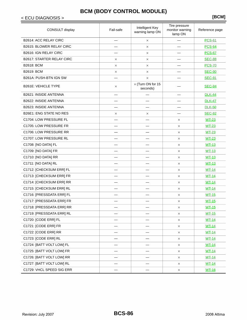
[BCM]BCM (BODY CONTROL MODULE)
< ECU DIAGNOSIS >
B2614: ACC RELAY CIRC — × — PCS-61
B2615: BLOWER RELAY CIRC — × — PCS-64
B2616: IGN RELAY CIRC — × — PCS-67
B2617: STARTER RELAY CIRC × × — SEC-88
B2618: BCM × × — PCS-70
B2619: BCM × × — SEC-90
B261A: PUSH-BTN IGN SW — × — SEC-91
B261E: VEHICLE TYPE × × (Turn ON for 15 seconds)
— SEC-94
B2621: INSIDE ANTENNA — — — DLK-44
B2622: INSIDE ANTENNA — — — DLK-47
B2623: INSIDE ANTENNA — — — DLK-50
B26E1: ENG STATE NO RES × × — SEC-82
C1704: LOW PRESSURE FL — — × WT-23
C1705: LOW PRESSURE FR — — × WT-23
C1706: LOW PRESSURE RR — — × WT-23
C1707: LOW PRESSURE RL — — × WT-23
C1708: [NO DATA] FL — — × WT-13
C1709: [NO DATA] FR — — × WT-13
C1710: [NO DATA] RR — — × WT-13
C1711: [NO DATA] RL — — × WT-13
C1712: [CHECKSUM ERR] FL — — × WT-14
C1713: [CHECKSUM ERR] FR — — × WT-14
C1714: [CHECKSUM ERR] RR — — × WT-14
C1715: [CHECKSUM ERR] RL — — × WT-14
C1716: [PRESSDATA ERR] FL — — × WT-15
C1717: [PRESSDATA ERR] FR — — × WT-15
C1718: [PRESSDATA ERR] RR — — × WT-15
C1719: [PRESSDATA ERR] RL — — × WT-15
C1720: [CODE ERR] FL — — × WT-14
C1721: [CODE ERR] FR — — × WT-14
C1722: [CODE ERR] RR — — × WT-14
C1723: [CODE ERR] RL — — × WT-14
C1724: [BATT VOLT LOW] FL — — × WT-14
C1725: [BATT VOLT LOW] FR — — × WT-14
C1726: [BATT VOLT LOW] RR — — × WT-14
C1727: [BATT VOLT LOW] RL — — × WT-14
C1729: VHCL SPEED SIG ERR — — × WT-16
CONSULT display Fail-safeIntelligent Key
warning lamp ON
Tire pressure monitor warning
lamp ONReference page
BCS-86

CS
COMBINATION SWITCH SYSTEM SYMPTOMS[BCM]
C
D
E
F
G
H
I
J
K
L
B
A
O
P
N
B
< SYMPTOM DIAGNOSIS >
SYMPTOM DIAGNOSISCOMBINATION SWITCH SYSTEM SYMPTOMS
Symptom Table INFOID:0000000001344684
1. Perform the data monitor of CONSULT-III to check for any malfunctioning item.2. Check the malfunction combinations.
Malfunction item: ×
3. Identify the malfunctioning part from the agreed combination and repair or replace the part.
Malfunction combi-nation
Data monitor item
FR
WIP
ER
HI
FR
WIP
ER
LO
W
FR
WA
SH
ER
SW
FR
WIP
ER
INT
INT
VO
LUM
E
TU
RN
SIG
NA
L R
TU
RN
SIG
NA
L L
TAIL
LA
MP
SW
HI B
EA
M S
W
HE
AD
LA
MP
SW
1
HE
AD
LA
MP
SW
2
PA
SS
ING
SW
AU
TO
LIG
HT
SW
FR
FO
G S
W
A × × × ×
B × × × ×
C × × ×
D × × ×
E × ×
F × ×
G × ×
H × × ×
I × × × ×
J × × × ×
K All Items
L If only one item is detected or the item is not applicable to the combinations A to K
Malfunction combination
Malfunctioning part Repair or replace
A Combination switch INPUT 1 circuit
Inspect the combination switch input circuit applicable to the malfunctioning part. Refer to BCS-37, "Diagnosis Procedure".
B Combination switch INPUT 2 circuit
C Combination switch INPUT 3 circuit
D Combination switch INPUT 4 circuit
E Combination switch INPUT 5 circuit
F Combination switch OUTPUT 1 circuit
Inspect the combination switch output circuit applicable to the malfunction-ing part. Refer to BCS-39, "Diagnosis Procedure".
G Combination switch OUTPUT 2 circuit
H Combination switch OUTPUT 3 circuit
I Combination switch OUTPUT 4 circuit
J Combination switch OUTPUT 5 circuit
K BCM Replace BCM. Refer to BCS-88, "Removal and Installation".
L Combination switchReplace the combination switch. Refer to WW-46, "Removal and Installa-tion".
BCS-87
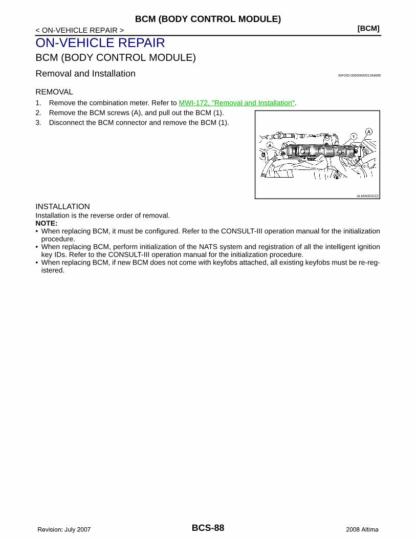
[BCM]BCM (BODY CONTROL MODULE)
< ON-VEHICLE REPAIR >
ON-VEHICLE REPAIRBCM (BODY CONTROL MODULE)
Removal and Installation INFOID:0000000001344685
REMOVAL1. Remove the combination meter. Refer to MWI-172, "Removal and Installation".2. Remove the BCM screws (A), and pull out the BCM (1).3. Disconnect the BCM connector and remove the BCM (1).
INSTALLATIONInstallation is the reverse order of removal.NOTE:• When replacing BCM, it must be configured. Refer to the CONSULT-III operation manual for the initialization
procedure.• When replacing BCM, perform initialization of the NATS system and registration of all the intelligent ignition
key IDs. Refer to the CONSULT-III operation manual for the initialization procedure. • When replacing BCM, if new BCM does not come with keyfobs attached, all existing keyfobs must be re-reg-
istered.
ALMIA0032ZZ
BCS-88