ELECTRICAL MACHINERY REPAIR; VOLUME 1, …€¦ · ELECTRICAL MACHINERY REPAIR; VOLUME 1, ELECTRIC...
390
[SGML VERSION: SEE CHANGE RECORD] TECHNICAL MANUAL ELECTRICAL MACHINERY REPAIR; VOLUME 1, ELECTRIC MOTOR, SHOP PROCEDURES MANUAL DISTRIBUTION STATEMENT A: APPROVED FOR PUBLIC RELEASE; DISTRIBUTION IS UNLIMITED. THIS MANUAL SUPERSEDES S6260-BJ-GTP-010, DATED 15 NOVEMBER 2005, AND ALL CHANGES THERETO. S6260-BJ-GTP-010 0910-LP-108-0244 VOLUME 1 REVISION 1 TITLE-1 / (TITLE-2 Blank)@@FIpgtype@@TITLE@@!FIpgtype@@ @@FIpgtype@@TITLE@@!FIpgtype@@ PUBLISHED BY DIRECTION OF COMMANDER, NAVAL SEA SYSTEMS COMMAND. 9 JUL 2009
Transcript of ELECTRICAL MACHINERY REPAIR; VOLUME 1, …€¦ · ELECTRICAL MACHINERY REPAIR; VOLUME 1, ELECTRIC...

[SGML VERSION: SEE CHANGERECORD]
TECHNICAL MANUAL
ELECTRICAL MACHINERYREPAIR;
VOLUME 1,ELECTRIC MOTOR,
SHOP PROCEDURESMANUAL
DISTRIBUTION STATEMENT A: APPROVED FOR PUBLIC RELEASE; DISTRIBUTION ISUNLIMITED.
THIS MANUAL SUPERSEDES S6260-BJ-GTP-010, DATED 15 NOVEMBER 2005, AND ALL CHANGES THERETO.
S6260-BJ-GTP-0100910-LP-108-0244 VOLUME 1
REVISION 1
TITLE-1 / (TITLE-2 Blank)@@FIpgtype@@TITLE@@!FIpgtype@@@@FIpgtype@@TITLE@@!FIpgtype@@
PUBLISHED BY DIRECTION OF COMMANDER, NAVAL SEA SYSTEMS COMMAND.
9 JUL 2009

TITLE-2@@FIpgtype@@BLANK@@!FIpgtype@@

RECORD OF CHANGESCHANGE NO. DATE TITLE OR BRIEF DESCRIPTION ENTERED BY
NOTE
THIS TECHNICAL MANUAL (TM) HAS BEEN DEVELOPED FROM AN INTELLIGENT ELECTRONICSOURCE KNOWN AS STANDARD GENERALIZED MARKUP LANGUAGE (SGML). THERE IS NOLOEP. ALL CHANGES, IF APPLICABLE, ARE INCLUDED. THE PAGINATION IN THIS TM WILL NOTMATCH THE PAGINATION OF THE ORIGINAL PAPER TM; HOWEVER, THE TECHNICAL CON-TENT IS EXACTLY THE SAME.
S6260-BJ-GTP-010
RECORD OF CHANGES-1 / (RECORD OF CHANGES-2 Blank)

RECORD OF CHANGES-2@@FIpgtype@@BLANK@@!FIpgtype@@
FOREWORD
This Electric Motor Repair Shop Procedures Manual is for use by IMA personnel engaged in electricmotor repair. For maximum effectiveness, this manual should be used as a supplement to any ongoing on-the-jobtraining in the IMA electrical repair shop.
Both mechanical and electrical test equipment and tools are discussed with detailed ″how-to-use″ informa-tion. This manual provides specific step-by-step inspection and test procedures with related safety precautions.Troubleshooting procedures with symptom recognition and listings of probable faults are explained. ″How-to-do-it″ step-by-step disassembly, checkout, repair, replacement and reassembly procedures are all illustrated with″hands-on″ diagrams for easy understanding. To ensure reliable equipment operation and equipment long life,installation procedures are provided with quality control provisions.
Navy equipment technical manuals and NAVSEA technical manuals provide the necessary instructionsabout what must be done for the maintenance and repair of equipment. This Shop Procedures Manual supple-ments the information in the preceding Navy references and other publications and provides the necessary detailson how the repair work is to be done to ensure equipment reliability.
This Electric Motor Repair Shop Procedures Manual has been developed with a primarily functional for-mat instead of a topical format. This is designed to facilitate equipment repairs. A repair technician finds usefulinformation in the necessary sequence and can perform a single task, or a related series of tasks, by referring toonly one section of the manual. Necessary descriptive information has been retained, but is presented as part ofthe relevant functional procedures. This functional format improves the effectiveness of the manual and is espe-cially suited to the improvement of technician performance.
Ships, training activities, supply points, depots, Naval Shipyards and Supervisors of Shipbuilding arerequested to arrange for the maximum practical use and evaluation of NAVSEA technical manuals. All errors,omissions, discrepancies and suggestions for improvement to NAVSEA technical manuals shall be forwarded to:COMMANDER,CODE 310 TMDER, BLDG 1388NAVSURFWARCENDIV NSDSA4363 MISSILE WAYPORT HUENEME CA 93043-4307on NAVSEA/SPAWAR Technical Manual Deficiency/Evaluation Report (TMDER), NAVSEA form 4160/1. Allfeedback comments shall be thoroughly investigated and originators will be advised of action resulting therefrom.One copy of NAVSEA form 4160/1 is at the end of each separately bound technical manual 8-1/2 x 11 inchesor larger. Copies of NAVSEA form 4160/1 may be requisitioned from the Naval Systems Data Support ActivityCode 310 at the above address. Users are encouraged to transmit deficiency submittals via the Naval SystemsData Support Activity web site located at:
https://nsdsa2.phdnswc.navy.mil/tmder/tmder-generate.asp?lvl=1
Individual electronic TMs do not contain NAVSEA form 4160/1 but are linked to an electronic version onthe resident CD-ROM. Therefore, we encourage the user to transmit deficiency submittals via the Naval SystemsData Support Activity web site located above.
S6260-BJ-GTP-010
FOREWORD-1 / (FOREWORD-2 Blank)

FOREWORD-2@@FIpgtype@@BLANK@@!FIpgtype@@

TABLE OF CONTENTS
Chapter/Paragraph Page
1 INTRODUCTION SECTION . . . . . . . . . . . . . . . . . . . . . . . . . . . . . . 1-1
1-1 SCOPE. . . . . . . . . . . . . . . . . . . . . . . . . . . . . . . . . . . . . . . . . . . . 1-1
SECTION I QUALITY ASSURANCE . . . . . . . . . . . . . . . . . . . . . . . . . . . . . . . . 1-1
1-2 INTRODUCTION TO QA. . . . . . . . . . . . . . . . . . . . . . . . . . . . . . . . . 1-1
1-4 DEFINITION OF TERMS. . . . . . . . . . . . . . . . . . . . . . . . . . . . . . . . . 1-21-5.1 Quality Control (QC). . . . . . . . . . . . . . . . . . . . . . . . . . . . . . . . 1-21-5.2 Quality Assurance (QA). . . . . . . . . . . . . . . . . . . . . . . . . . . . . . 1-21-5.3 Objective Quality. . . . . . . . . . . . . . . . . . . . . . . . . . . . . . . . . . 1-21-5.4 Controlled Material. . . . . . . . . . . . . . . . . . . . . . . . . . . . . . . . . 1-21-5.5 Formal Work Procedures (FWP). . . . . . . . . . . . . . . . . . . . . . . . . 1-21-5.6 Material Identification and Control (MIC) Number. . . . . . . . . . . . . . . 1-21-5.7 Certified Level I Material. . . . . . . . . . . . . . . . . . . . . . . . . . . . . 1-2
1-6 WORK PACKAGES. . . . . . . . . . . . . . . . . . . . . . . . . . . . . . . . . . . . 1-3
1-8 CRITICAL QUALITY CONTROL POINTS. . . . . . . . . . . . . . . . . . . . . . . 1-3
1-9 SHIPS MAINTENANCE ACTION FORM (OPNAV Form 4790/2K). . . . . . . . . 1-4
1-10 MAINTENANCE PLANNING AND ESTIMATING FORM (OPNAV Form4790/2P). . . . . . . . . . . . . . . . . . . . . . . . . . . . . . . . . . . . . . . . . . 1-4
1-11 CONTROLLED WORK PACKAGES (CWPs). . . . . . . . . . . . . . . . . . . . . . 1-4
1-12 LEVELS OF ASSURANCE. . . . . . . . . . . . . . . . . . . . . . . . . . . . . . . . 1-41-13.1 Level A. . . . . . . . . . . . . . . . . . . . . . . . . . . . . . . . . . . . . . . 1-51-13.2 Level B. . . . . . . . . . . . . . . . . . . . . . . . . . . . . . . . . . . . . . . 1-51-13.3 Level C. . . . . . . . . . . . . . . . . . . . . . . . . . . . . . . . . . . . . . . 1-5
1-14 MATERIAL REQUIREMENTS. . . . . . . . . . . . . . . . . . . . . . . . . . . . . . 1-9
1-16 DEPARTURES FROM SPECIFICATIONS. . . . . . . . . . . . . . . . . . . . . . . . 1-101-17.2 Reporting Departures from Specifications. . . . . . . . . . . . . . . . . . . . 1-101-17.3 Types of Departures from Specification. . . . . . . . . . . . . . . . . . . . . . 1-101-17.4 Permanent and Temporary Approval of Departure from Specification. . . . . 1-11
1-18 RESPONSIBILITIES OF SHOP QUALITY CONTROL INSPECTOR (QCI). . . . . 1-11
1-20 RESPONSIBILITIES OF REPAIR PERSONNEL. . . . . . . . . . . . . . . . . . . . 1-12
SECTION II INTRODUCTION TO TAG-OUT . . . . . . . . . . . . . . . . . . . . . . . . . . . 1-13
1-22 INTRODUCTION TO TAG-OUT. . . . . . . . . . . . . . . . . . . . . . . . . . . . . 1-13
S6260-BJ-GTP-010
i

TABLE OF CONTENTS - Continued
Chapter/Paragraph Page
1-24 TAG-OUT RESPONSIBILITIES. . . . . . . . . . . . . . . . . . . . . . . . . . . . . . 1-13
1-25 TAG-OUT PLANNING. . . . . . . . . . . . . . . . . . . . . . . . . . . . . . . . . . . 1-14
1-26 TAGS AND RECORDS. . . . . . . . . . . . . . . . . . . . . . . . . . . . . . . . . . 1-141-27.1 CAUTION Tag. . . . . . . . . . . . . . . . . . . . . . . . . . . . . . . . . . . 1-141-27.2 DANGER Tag. . . . . . . . . . . . . . . . . . . . . . . . . . . . . . . . . . . 1-141-27.3 DANGER/CAUTION Tag-out Record Sheet. . . . . . . . . . . . . . . . . . . 1-141-27.4 Tag-out Log. . . . . . . . . . . . . . . . . . . . . . . . . . . . . . . . . . . . . 1-141-27.5 Preparation of Tags and Record Sheets. . . . . . . . . . . . . . . . . . . . . . 1-14
1-28 TAG-OUT OF ELECTRIC MOTORS. . . . . . . . . . . . . . . . . . . . . . . . . . . 1-15
SECTION III ELECTRIC MOTOR REPAIR . . . . . . . . . . . . . . . . . . . . . . . . . . . . . 1-20
1-30 INTRODUCTION TO ELECTRIC MOTORS. . . . . . . . . . . . . . . . . . . . . . 1-20
1-32 MOTOR RATINGS. . . . . . . . . . . . . . . . . . . . . . . . . . . . . . . . . . . . . 1-20
1-33 VOLTAGE AND FREQUENCY VARIATIONS. . . . . . . . . . . . . . . . . . . . . 1-20
1-34 DESCRIPTION OF AC MOTORS. . . . . . . . . . . . . . . . . . . . . . . . . . . . . 1-20
1-35 FUNCTIONS OF THE ELECTRICAL REPAIR SHOP. . . . . . . . . . . . . . . . . 1-21
2 TEST EQUIPMENT AND MEASURING INSTRUMENTS . . . . . . . . . . . . 2-1
2-1 SCOPE. . . . . . . . . . . . . . . . . . . . . . . . . . . . . . . . . . . . . . . . . . . . 2-1
2-2 PURPOSES OF TYPICAL ELECTRICAL TEST EQUIPMENT. . . . . . . . . . . . 2-12-3.1 Measurement of Insulation Resistance. . . . . . . . . . . . . . . . . . . . . . 2-12-3.2 Measurement of Winding Resistances. . . . . . . . . . . . . . . . . . . . . . 2-22-3.3 Phase Comparison of Windings. . . . . . . . . . . . . . . . . . . . . . . . . . 2-22-3.4 Measurement of Phase Current. . . . . . . . . . . . . . . . . . . . . . . . . . 2-22-3.5 DC High-Potential Test. . . . . . . . . . . . . . . . . . . . . . . . . . . . . . 2-22-3.6 Polarization Index Test. . . . . . . . . . . . . . . . . . . . . . . . . . . . . . . 2-22-3.7 AC High-Potential Test. . . . . . . . . . . . . . . . . . . . . . . . . . . . . . 2-22-3.8 Core Test. . . . . . . . . . . . . . . . . . . . . . . . . . . . . . . . . . . . . . 2-2
2-4 GENERAL RADIO MEGOHM BRIDGE. TYPE 1644A. . . . . . . . . . . . . . . . 2-2
2-6 CONTROLS AND CONNECTORS. . . . . . . . . . . . . . . . . . . . . . . . . . . . 2-4
2-7 OPERATION. . . . . . . . . . . . . . . . . . . . . . . . . . . . . . . . . . . . . . . . 2-4
2-8 GENERAL RADIO MEGOHMMETER, TYPE 1863. . . . . . . . . . . . . . . . . . 2-7
2-10 RANGE. . . . . . . . . . . . . . . . . . . . . . . . . . . . . . . . . . . . . . . . . . . 2-8
S6260-BJ-GTP-010
ii

TABLE OF CONTENTS - Continued
Chapter/Paragraph Page
2-11 CONTROLS AND CONNECTORS. . . . . . . . . . . . . . . . . . . . . . . . . . . . 2-9
2-12 PREPARATION. . . . . . . . . . . . . . . . . . . . . . . . . . . . . . . . . . . . . . . 2-9
2-13 MEASUREMENT SETUP. . . . . . . . . . . . . . . . . . . . . . . . . . . . . . . . . 2-10
2-14 MEASUREMENT PROCEDURE. . . . . . . . . . . . . . . . . . . . . . . . . . . . . 2-13
2-15 VALHALLA DIGITAL OHMMETER. . . . . . . . . . . . . . . . . . . . . . . . . . . 2-14
2-17 CONTROLS AND CONNECTORS. . . . . . . . . . . . . . . . . . . . . . . . . . . . 2-14
2-18 OPERATION. . . . . . . . . . . . . . . . . . . . . . . . . . . . . . . . . . . . . . . . 2-15
2-19 BAKER ST112E SURGE/DC HIGH-POTENTIAL TESTER. . . . . . . . . . . . . . 2-18
2-21 CONTROLS AND CONNECTORS. . . . . . . . . . . . . . . . . . . . . . . . . . . . 2-19
2-22 OPERATION. . . . . . . . . . . . . . . . . . . . . . . . . . . . . . . . . . . . . . . . 2-19
2-23 OPERATION. . . . . . . . . . . . . . . . . . . . . . . . . . . . . . . . . . . . . . . . 2-24
2-24 EXTERNAL GROWLER. . . . . . . . . . . . . . . . . . . . . . . . . . . . . . . . . . 2-26
2-25 TYPICAL CLAMP-ON AMMETER. . . . . . . . . . . . . . . . . . . . . . . . . . . 2-28
2-27 CONTROLS AND CONNECTORS. . . . . . . . . . . . . . . . . . . . . . . . . . . . 2-28
2-28 OPERATION. . . . . . . . . . . . . . . . . . . . . . . . . . . . . . . . . . . . . . . . 2-29
2-29 TYPICAL DIGITAL AC/DC CLAMP-ON MULTIMETER. . . . . . . . . . . . . . . 2-31
2-31 CONTROLS AND CONNECTORS. . . . . . . . . . . . . . . . . . . . . . . . . . . . 2-32
2-32 OPERATION. . . . . . . . . . . . . . . . . . . . . . . . . . . . . . . . . . . . . . . . 2-32
2-33 STROBOTAC, TYPE 1531-AB. . . . . . . . . . . . . . . . . . . . . . . . . . . . . . 2-36
2-35 CONTROLS. . . . . . . . . . . . . . . . . . . . . . . . . . . . . . . . . . . . . . . . . 2-36
2-36 OPERATION. . . . . . . . . . . . . . . . . . . . . . . . . . . . . . . . . . . . . . . . 2-36
2-37 POLARIZATION INDEX TEST. . . . . . . . . . . . . . . . . . . . . . . . . . . . . . 2-39
2-38 LEXSECO CORE TESTER 1081D. . . . . . . . . . . . . . . . . . . . . . . . . . . . 2-41
2-39 AC DIELECTRIC TEST SET, HIPOTRONICS, INC., MODEL 710-1. . . . . . . . . 2-42
S6260-BJ-GTP-010
iii
TABLE OF CONTENTS - Continued
Chapter/Paragraph Page
2-41 CONTROLS. . . . . . . . . . . . . . . . . . . . . . . . . . . . . . . . . . . . . . . . . 2-42
2-42 CONNECTIONS. . . . . . . . . . . . . . . . . . . . . . . . . . . . . . . . . . . . . . 2-43
2-43 INTERLOCK SWITCH. . . . . . . . . . . . . . . . . . . . . . . . . . . . . . . . . . . 2-45
2-44 OPERATION. . . . . . . . . . . . . . . . . . . . . . . . . . . . . . . . . . . . . . . . 2-45
2-45 AC AND DC DIELECTRIC TEST SET, HIPOTRONICS, INC., MODEL 115-A. . . 2-47
2-47 CONTROLS. . . . . . . . . . . . . . . . . . . . . . . . . . . . . . . . . . . . . . . . . 2-47
2-48 SETUP. . . . . . . . . . . . . . . . . . . . . . . . . . . . . . . . . . . . . . . . . . . . 2-48
2-49 OPERATION. . . . . . . . . . . . . . . . . . . . . . . . . . . . . . . . . . . . . . . . 2-48
2-50 DC HIPOT TESTING. . . . . . . . . . . . . . . . . . . . . . . . . . . . . . . . . . . . 2-48
2-51 AC HIPOT TESTING. . . . . . . . . . . . . . . . . . . . . . . . . . . . . . . . . . . . 2-51
2-52 OVERLOAD ADJUSTMENT. . . . . . . . . . . . . . . . . . . . . . . . . . . . . . . 2-512-52.2 Adjusting the Overload. . . . . . . . . . . . . . . . . . . . . . . . . . . . . . 2-51
2-53 TYPICAL DIAL INDICATOR. . . . . . . . . . . . . . . . . . . . . . . . . . . . . . . 2-52
2-55 MEASURING SHAFT RADIAL RUNOUT IN PLACE. . . . . . . . . . . . . . . . . 2-53
2-56 MEASURING FACE RUNOUT OF BEARING, INNER RING. . . . . . . . . . . . 2-55
2-57 MEASURING FACE RUNOUT OF BEARING OUTER RING. . . . . . . . . . . . 2-55
2-58 TYPICAL BORE GAGE AND RING MASTER. . . . . . . . . . . . . . . . . . . . . 2-58
2-60 CALIBRATION. . . . . . . . . . . . . . . . . . . . . . . . . . . . . . . . . . . . . . . 2-58
2-61 PROCEDURE FOR USE OF A BORE GAGE. . . . . . . . . . . . . . . . . . . . . . 2-58
2-62 TYPICAL SNAP GAGE. . . . . . . . . . . . . . . . . . . . . . . . . . . . . . . . . . 2-61
2-64 SETTING THE SNAP GAGE. . . . . . . . . . . . . . . . . . . . . . . . . . . . . . . 2-61
2-65 MEASUREMENT. . . . . . . . . . . . . . . . . . . . . . . . . . . . . . . . . . . . . . 2-64
3 IN-PLACE ELECTRICAL AND MECHANICAL TROUBLESHOOTING . . . 3-1
3-1 SCOPE. . . . . . . . . . . . . . . . . . . . . . . . . . . . . . . . . . . . . . . . . . . . 3-1
3-2 IN-PLACE TEST AND INSPECTION. . . . . . . . . . . . . . . . . . . . . . . . . . 3-1
S6260-BJ-GTP-010
iv
TABLE OF CONTENTS - Continued
Chapter/Paragraph Page
3-3 MOTOR DATA SHEET. . . . . . . . . . . . . . . . . . . . . . . . . . . . . . . . . . . 3-1
3-4 VISUAL INSPECTION PROCEDURES. . . . . . . . . . . . . . . . . . . . . . . . . 3-2
3-5 ELECTRICAL TEST PROCEDURES. . . . . . . . . . . . . . . . . . . . . . . . . . . 3-33-5.1 Winding Continuity and Resistance Test. . . . . . . . . . . . . . . . . . . . . 3-33-5.2 Insulation Resistance Test. . . . . . . . . . . . . . . . . . . . . . . . . . . . . 3-43-5.3 Controller and Cable Insulation Resistance Test. . . . . . . . . . . . . . . . . 3-4
3-6 MECHANICAL INSPECTION PROCEDURES. . . . . . . . . . . . . . . . . . . . . 3-5
3-8 VISUAL INSPECTION. . . . . . . . . . . . . . . . . . . . . . . . . . . . . . . . . . . 3-6
3-9 BEARING RUNOUT TEST PROCEDURES. . . . . . . . . . . . . . . . . . . . . . . 3-9
3-10 OPERATIONAL TEST PROCEDURES. . . . . . . . . . . . . . . . . . . . . . . . . . 3-10
4 RIGGING AND TRANSPORTATION . . . . . . . . . . . . . . . . . . . . . . . . . 4-1
4-1 SCOPE. . . . . . . . . . . . . . . . . . . . . . . . . . . . . . . . . . . . . . . . . . . . 4-1
4-2 PREPARATION FOR MOVING. . . . . . . . . . . . . . . . . . . . . . . . . . . . . . 4-1
4-4 MOTOR LOCATION AND REMOVAL ROUTE. . . . . . . . . . . . . . . . . . . . 4-14-4.2 Check headroom. . . . . . . . . . . . . . . . . . . . . . . . . . . . . . . . . . 4-1
4-5 RIGGING INSPECTION. . . . . . . . . . . . . . . . . . . . . . . . . . . . . . . . . . 4-1
4-6 DISCONNECTING THE MOTOR. . . . . . . . . . . . . . . . . . . . . . . . . . . . 4-2
4-7 RIGGING FUNDAMENTALS. . . . . . . . . . . . . . . . . . . . . . . . . . . . . . . 4-3
4-8 HANDLING PROCEDURES AND PRECAUTIONS. . . . . . . . . . . . . . . . . . 4-3
4-9 RIGGING COMPONENTS. . . . . . . . . . . . . . . . . . . . . . . . . . . . . . . . . 4-4
4-10 WIRE ROPE CLAMPS. . . . . . . . . . . . . . . . . . . . . . . . . . . . . . . . . . . 4-4
4-11 WIRE ROPE FITTINGS. . . . . . . . . . . . . . . . . . . . . . . . . . . . . . . . . . 4-7
4-12 HOOKS AND SHACKLES. . . . . . . . . . . . . . . . . . . . . . . . . . . . . . . . 4-7
4-13 CHAIN HOISTS. . . . . . . . . . . . . . . . . . . . . . . . . . . . . . . . . . . . . . . 4-7
4-14 WINCHES. . . . . . . . . . . . . . . . . . . . . . . . . . . . . . . . . . . . . . . . . . 4-9
4-15 TRANSPORTING THE MOTOR. . . . . . . . . . . . . . . . . . . . . . . . . . . . . 4-10
S6260-BJ-GTP-010
v
TABLE OF CONTENTS - Continued
Chapter/Paragraph Page
4-16 ATTACHING THE RIG. . . . . . . . . . . . . . . . . . . . . . . . . . . . . . . . . . 4-10
4-17 HOISTING. . . . . . . . . . . . . . . . . . . . . . . . . . . . . . . . . . . . . . . . . . 4-12
4-18 TRANSPORTATION. . . . . . . . . . . . . . . . . . . . . . . . . . . . . . . . . . . . 4-13
4-19 MOTOR ROTOR TRANSPORT. . . . . . . . . . . . . . . . . . . . . . . . . . . . . . 4-15
5 IN-SHOP ELECTRIC MOTOR INSPECTION AND DISASSEMBLY . . . . . . 5-1
5-1 SCOPE. . . . . . . . . . . . . . . . . . . . . . . . . . . . . . . . . . . . . . . . . . . . 5-1
5-2 ELECTRIC SHOP RECORDS. . . . . . . . . . . . . . . . . . . . . . . . . . . . . . . 5-1
5-4 WORK PACKAGE. . . . . . . . . . . . . . . . . . . . . . . . . . . . . . . . . . . . . 5-15-4.1 Automated Work Request (AWR). . . . . . . . . . . . . . . . . . . . . . . . . 5-15-4.2 Maintenance Planning and Estimating Form. . . . . . . . . . . . . . . . . . . 5-15-4.3 Formal Work Procedure (FWP). . . . . . . . . . . . . . . . . . . . . . . . . . 5-15-4.4 Quality Assurance Documents. . . . . . . . . . . . . . . . . . . . . . . . . . . 5-15-4.5 In-place Mechanical and Electrical Data Sheets. . . . . . . . . . . . . . . . . 5-1
5-5 WINDING DATA. . . . . . . . . . . . . . . . . . . . . . . . . . . . . . . . . . . . . . 5-2
5-6 INSPECTIONS. . . . . . . . . . . . . . . . . . . . . . . . . . . . . . . . . . . . . . . 5-2
5-7 INITIAL MECHANICAL INSPECTION PROCEDURES. . . . . . . . . . . . . . . . 5-2
5-8 VISUAL INSPECTION. . . . . . . . . . . . . . . . . . . . . . . . . . . . . . . . . . . 5-2
5-9 SHAFT RADIAL RUNOUT. . . . . . . . . . . . . . . . . . . . . . . . . . . . . . . . 5-2
5-10 BEARING INNER FACE AXIAL SQUARENESS (FACE RUNOUT). . . . . . . . . 5-5
5-11 DISASSEMBLY PROCEDURE. . . . . . . . . . . . . . . . . . . . . . . . . . . . . . 5-5
5-12 PRELIMINARY PREPARATION. . . . . . . . . . . . . . . . . . . . . . . . . . . . . 5-5
5-13 END BELL REMOVAL. . . . . . . . . . . . . . . . . . . . . . . . . . . . . . . . . . 5-6
5-14 ROTOR REMOVAL. . . . . . . . . . . . . . . . . . . . . . . . . . . . . . . . . . . . 5-9
5-15 BEARING AND END CAP INSPECTION. . . . . . . . . . . . . . . . . . . . . . . . 5-11
5-16 ROTOR INSPECTION. . . . . . . . . . . . . . . . . . . . . . . . . . . . . . . . . . . 5-11
5-17 ROTOR TEST. . . . . . . . . . . . . . . . . . . . . . . . . . . . . . . . . . . . . . . . 5-12
5-18 ELECTRICAL INSPECTION. . . . . . . . . . . . . . . . . . . . . . . . . . . . . . . 5-13
S6260-BJ-GTP-010
vi
TABLE OF CONTENTS - Continued
Chapter/Paragraph Page
5-19 INSULATION RESISTANCE (IR) TEST. . . . . . . . . . . . . . . . . . . . . . . . . 5-13
5-20 POLARIZATION INDEX (PI) TEST. . . . . . . . . . . . . . . . . . . . . . . . . . . 5-14
5-21 SURGE COMPARISON TEST. . . . . . . . . . . . . . . . . . . . . . . . . . . . . . . 5-14
5-22 PHASE RESISTANCE BALANCE TEST. . . . . . . . . . . . . . . . . . . . . . . . . 5-14
5-23 HIGH-POTENTIAL TEST. . . . . . . . . . . . . . . . . . . . . . . . . . . . . . . . . 5-15
5-24 CORE TEST. . . . . . . . . . . . . . . . . . . . . . . . . . . . . . . . . . . . . . . . . 5-15
6 MOTOR BEARINGS AND BEARING PROBLEMS . . . . . . . . . . . . . . . . 6-1
6-1 SCOPE. . . . . . . . . . . . . . . . . . . . . . . . . . . . . . . . . . . . . . . . . . . . 6-1
6-2 TYPES OF MOTOR BEARINGS. . . . . . . . . . . . . . . . . . . . . . . . . . . . . 6-1
6-3 BEARING DESIGNATIONS . . . . . . . . . . . . . . . . . . . . . . . . . . . . . . . 6-16-3.1 Rolling-Element Bearings. . . . . . . . . . . . . . . . . . . . . . . . . . . . . 6-16-3.2 Needle and Cylindrical Roller Bearings. . . . . . . . . . . . . . . . . . . . . 6-26-3.3 Sliding Bearings. . . . . . . . . . . . . . . . . . . . . . . . . . . . . . . . . . 6-26-3.4 Tilting-pad Journal Bearings. . . . . . . . . . . . . . . . . . . . . . . . . . . . 6-2
6-4 BALL BEARINGS. . . . . . . . . . . . . . . . . . . . . . . . . . . . . . . . . . . . . 6-2
6-5 CHARACTERISTICS OF BALL BEARINGS. . . . . . . . . . . . . . . . . . . . . . 6-26-5.7 Precision. . . . . . . . . . . . . . . . . . . . . . . . . . . . . . . . . . . . . . . 6-36-5.8 Limitations. . . . . . . . . . . . . . . . . . . . . . . . . . . . . . . . . . . . . 6-3
6-6 BEARING IDENTIFICATION. . . . . . . . . . . . . . . . . . . . . . . . . . . . . . . 6-36-6.1 National Stock Numbers (NSN). . . . . . . . . . . . . . . . . . . . . . . . . . 6-36-6.2 Allowance Part List (APL). . . . . . . . . . . . . . . . . . . . . . . . . . . . 6-36-6.3 Bearing Type. . . . . . . . . . . . . . . . . . . . . . . . . . . . . . . . . . . . 6-36-6.4 Basic Bearing Number. . . . . . . . . . . . . . . . . . . . . . . . . . . . . . . 6-4
6-7 BEARING DESIGN. . . . . . . . . . . . . . . . . . . . . . . . . . . . . . . . . . . . . 6-5
6-8 BEARING DESIGN FEATURES . . . . . . . . . . . . . . . . . . . . . . . . . . . . . 6-56-8.1 Ball Bearings. . . . . . . . . . . . . . . . . . . . . . . . . . . . . . . . . . . . 6-56-8.2 Bearing Cages. . . . . . . . . . . . . . . . . . . . . . . . . . . . . . . . . . . 6-86-8.3 Seals and Shields. . . . . . . . . . . . . . . . . . . . . . . . . . . . . . . . . . 6-86-8.4 Radial Internal Clearance. . . . . . . . . . . . . . . . . . . . . . . . . . . . . 6-86-8.5 Mounting Design. . . . . . . . . . . . . . . . . . . . . . . . . . . . . . . . . . 6-96-8.6 Shaft and Housing Design. . . . . . . . . . . . . . . . . . . . . . . . . . . . . 6-10
6-9 CARE OF UNMOUNTED BEARINGS. . . . . . . . . . . . . . . . . . . . . . . . . . 6-136-9.1 Handling and Storage. . . . . . . . . . . . . . . . . . . . . . . . . . . . . . . 6-13
S6260-BJ-GTP-010
vii
TABLE OF CONTENTS - Continued
Chapter/Paragraph Page
6-9.2 Inspection. . . . . . . . . . . . . . . . . . . . . . . . . . . . . . . . . . . . . . 6-146-9.3 Cleaning. . . . . . . . . . . . . . . . . . . . . . . . . . . . . . . . . . . . . . . 6-15
6-9.3.1 New Bearings. . . . . . . . . . . . . . . . . . . . . . . . . . . . . 6-156-9.3.2 Used Bearings. . . . . . . . . . . . . . . . . . . . . . . . . . . . . 6-15
6-10 SAFETY PRECAUTIONS. . . . . . . . . . . . . . . . . . . . . . . . . . . . . . . . . 6-15
6-11 CARE OF MOUNTED BEARINGS. . . . . . . . . . . . . . . . . . . . . . . . . . . . 6-16
6-12 HANDLING, MAINTENANCE AND LUBRICATION OF MOUNTED BEARINGS. . . . . . . . . . . . . . . . . . . . . . . . . . . . . . . . . . . . . . . . . . . . . . 6-16
6-12.1 Handling and Storage. . . . . . . . . . . . . . . . . . . . . . . . . . . . . . . 6-166-12.2 Maintenance. . . . . . . . . . . . . . . . . . . . . . . . . . . . . . . . . . . . . 6-17
6-12.2.1 Preoperational Inspection. . . . . . . . . . . . . . . . . . . . . . . 6-176-12.2.2 In-Service Inspection. . . . . . . . . . . . . . . . . . . . . . . . . 6-176-12.2.3 Temperature. . . . . . . . . . . . . . . . . . . . . . . . . . . . . . 6-17
6-12.2.3.4 Excessive loading of the bearing. . . . . . . . . 6-186-12.2.3.5 Error in alignment during mounting. . . . . . . 6-186-12.2.3.6 Tight-fitting seals. . . . . . . . . . . . . . . . . 6-18
6-12.2.4 Noise and Vibration. . . . . . . . . . . . . . . . . . . . . . . . . . 6-186-12.2.4.1 Squeaking noise. . . . . . . . . . . . . . . . . . 6-196-12.2.4.2 Metallic Tone. . . . . . . . . . . . . . . . . . . 6-196-12.2.4.3 Smooth, Clear Tone. . . . . . . . . . . . . . . . 6-196-12.2.4.4 Intermittent Noise. . . . . . . . . . . . . . . . . 6-196-12.2.4.5 Crunching Noise. . . . . . . . . . . . . . . . . . 6-19
6-12.3 Lubrication. . . . . . . . . . . . . . . . . . . . . . . . . . . . . . . . . . . . . 6-196-12.3.2 Characteristics of Grease. . . . . . . . . . . . . . . . . . . . . . . 6-196-12.3.3 Grease Lubrication. . . . . . . . . . . . . . . . . . . . . . . . . . 6-206-12.3.4 Grease Addition. . . . . . . . . . . . . . . . . . . . . . . . . . . . 6-206-12.3.5 Grease Replacement. . . . . . . . . . . . . . . . . . . . . . . . . 6-216-12.3.7 Oil Lubrication. . . . . . . . . . . . . . . . . . . . . . . . . . . . 6-23
6-13 NOISE-TESTED BEARINGS. . . . . . . . . . . . . . . . . . . . . . . . . . . . . . . 6-236-13.1 Raw Steel Stock. . . . . . . . . . . . . . . . . . . . . . . . . . . . . . . . . . 6-23
6-14 MECHANICAL DAMAGE. . . . . . . . . . . . . . . . . . . . . . . . . . . . . . . . . 6-23
6-15 CORROSION. . . . . . . . . . . . . . . . . . . . . . . . . . . . . . . . . . . . . . . . 6-236-15.1 Rust. . . . . . . . . . . . . . . . . . . . . . . . . . . . . . . . . . . . . . . . . 6-236-15.2 Reactions. . . . . . . . . . . . . . . . . . . . . . . . . . . . . . . . . . . . . . 6-236-15.3 Fretting. . . . . . . . . . . . . . . . . . . . . . . . . . . . . . . . . . . . . . . 6-23
6-16 ELECTRIC ARCING. . . . . . . . . . . . . . . . . . . . . . . . . . . . . . . . . . . . 6-23
6-17 BEARING REPLACEMENT. . . . . . . . . . . . . . . . . . . . . . . . . . . . . . . . 6-246-17.1 Preliminary Inspection. . . . . . . . . . . . . . . . . . . . . . . . . . . . . . . 6-24
6-17.1.1 Freedom of rotation. . . . . . . . . . . . . . . . . . . . . . . . . . 6-24
S6260-BJ-GTP-010
viii

TABLE OF CONTENTS - Continued
Chapter/Paragraph Page
6-17.1.2 Excessive heating of the bearings. . . . . . . . . . . . . . . . . . 6-246-17.1.3 Excessive bearing noise. . . . . . . . . . . . . . . . . . . . . . . 6-246-17.1.4 Lose or broken bolts or parts. . . . . . . . . . . . . . . . . . . . 6-246-17.1.7 Coastdown time. . . . . . . . . . . . . . . . . . . . . . . . . . . . 6-24
6-18 WORK AREA AND TOOLS. . . . . . . . . . . . . . . . . . . . . . . . . . . . . . . . 6-24
6-19 CLEANLINESS. . . . . . . . . . . . . . . . . . . . . . . . . . . . . . . . . . . . . . . 6-25
6-20 TOOLS. . . . . . . . . . . . . . . . . . . . . . . . . . . . . . . . . . . . . . . . . . . . 6-256-20.1 Arbor Press. . . . . . . . . . . . . . . . . . . . . . . . . . . . . . . . . . . . . 6-256-20.2 Hand Tools. . . . . . . . . . . . . . . . . . . . . . . . . . . . . . . . . . . . . 6-256-20.3 Bearing Pullers. . . . . . . . . . . . . . . . . . . . . . . . . . . . . . . . . . . 6-256-20.4 Torque Wrenches. . . . . . . . . . . . . . . . . . . . . . . . . . . . . . . . . . 6-266-20.5 Convection Oven. . . . . . . . . . . . . . . . . . . . . . . . . . . . . . . . . . 6-266-20.6 Bore Heater. . . . . . . . . . . . . . . . . . . . . . . . . . . . . . . . . . . . . 6-266-20.7 Induction Heater. . . . . . . . . . . . . . . . . . . . . . . . . . . . . . . . . . 6-266-20.8 Oil Bath. . . . . . . . . . . . . . . . . . . . . . . . . . . . . . . . . . . . . . . 6-266-20.9 Wiping and Handling Materials. . . . . . . . . . . . . . . . . . . . . . . . . . 6-27
6-20.10 Grease. . . . . . . . . . . . . . . . . . . . . . . . . . . . . . . . . . . . . . . . 6-286-20.11 Measuring Instruments. . . . . . . . . . . . . . . . . . . . . . . . . . . . . . . 6-28
6-21 DISASSEMBLY AND BEARING REMOVAL. . . . . . . . . . . . . . . . . . . . . . 6-28
6-22 GENERAL INFORMATION. . . . . . . . . . . . . . . . . . . . . . . . . . . . . . . . 6-28
6-23 BEARING REMOVAL. . . . . . . . . . . . . . . . . . . . . . . . . . . . . . . . . . . 6-286-23.1 Arbor Press Method. . . . . . . . . . . . . . . . . . . . . . . . . . . . . . . . 6-286-23.2 Puller Method. . . . . . . . . . . . . . . . . . . . . . . . . . . . . . . . . . . . 6-296-23.3 Seized Bearing. . . . . . . . . . . . . . . . . . . . . . . . . . . . . . . . . . . 6-29
6-24 COMPONENT INSPECTION AND REPAIR. . . . . . . . . . . . . . . . . . . . . . . 6-34
6-25 BEARING INSTALLATION AND ASSEMBLY. . . . . . . . . . . . . . . . . . . . . 6-386-25.5 Bearing Locknuts. . . . . . . . . . . . . . . . . . . . . . . . . . . . . . . . . . 6-41
6-26 HEAT SOURCE METHOD. . . . . . . . . . . . . . . . . . . . . . . . . . . . . . . . 6-42
6-27 ARBOR PRESS METHOD. . . . . . . . . . . . . . . . . . . . . . . . . . . . . . . . . 6-43
6-28 PARALLEL BLOCK METHOD. . . . . . . . . . . . . . . . . . . . . . . . . . . . . . 6-43
6-29 EMERGENCY METHOD. . . . . . . . . . . . . . . . . . . . . . . . . . . . . . . . . 6-44
6-30 SPECIAL PROCEDURES FOR DUPLEX BEARINGS. . . . . . . . . . . . . . . . . 6-44
6-32 BEARING LOCKNUT TORQUES. . . . . . . . . . . . . . . . . . . . . . . . . . . . 6-49
S6260-BJ-GTP-010
ix

TABLE OF CONTENTS - Continued
Chapter/Paragraph Page
6-33 GREASE PACK. . . . . . . . . . . . . . . . . . . . . . . . . . . . . . . . . . . . . . . 6-49
6-34 PRELOAD SPRINGS. . . . . . . . . . . . . . . . . . . . . . . . . . . . . . . . . . . . 6-49
6-35 AXIAL RUNOUT. . . . . . . . . . . . . . . . . . . . . . . . . . . . . . . . . . . . . . 6-496-35.1 Alignment. . . . . . . . . . . . . . . . . . . . . . . . . . . . . . . . . . . . . . 6-49
6-36 OIL LUBRICATION. . . . . . . . . . . . . . . . . . . . . . . . . . . . . . . . . . . . 6-50
6-37 POSTREPAIR INSPECTION. . . . . . . . . . . . . . . . . . . . . . . . . . . . . . . . 6-506-38.1 Torque. . . . . . . . . . . . . . . . . . . . . . . . . . . . . . . . . . . . . . . . 6-506-38.2 Noise. . . . . . . . . . . . . . . . . . . . . . . . . . . . . . . . . . . . . . . . 6-506-38.3 Temperature. . . . . . . . . . . . . . . . . . . . . . . . . . . . . . . . . . . . . 6-506-38.4 Recordkeeping. . . . . . . . . . . . . . . . . . . . . . . . . . . . . . . . . . . 6-506-38.5 Reinstallation Tests. . . . . . . . . . . . . . . . . . . . . . . . . . . . . . . . . 6-50
6-39 MOTOR BEARING CONVERSION: EXTENDED-LIFE DOUBLE SEAL BALLBEARINGS . . . . . . . . . . . . . . . . . . . . . . . . . . . . . . . . . . . . . . . 6-52
6-39.2 Applicability. . . . . . . . . . . . . . . . . . . . . . . . . . . . . . . . . . . . 6-536-39.3 Motor Criteria. . . . . . . . . . . . . . . . . . . . . . . . . . . . . . . . . . . . 6-53
7 PREPARATION FOR MOTOR RECONDITIONING . . . . . . . . . . . . . . . 7-1
7-1 SCOPE. . . . . . . . . . . . . . . . . . . . . . . . . . . . . . . . . . . . . . . . . . . . 7-1
7-2 CLEANING THE MOTOR. . . . . . . . . . . . . . . . . . . . . . . . . . . . . . . . . 7-1
7-3 METHODS OF CLEANING. . . . . . . . . . . . . . . . . . . . . . . . . . . . . . . . 7-1
7-4 SUCTION. . . . . . . . . . . . . . . . . . . . . . . . . . . . . . . . . . . . . . . . . . 7-1
7-5 WIPING. . . . . . . . . . . . . . . . . . . . . . . . . . . . . . . . . . . . . . . . . . . 7-2
7-6 CLEANING WITH AIR PRESSURE. . . . . . . . . . . . . . . . . . . . . . . . . . . 7-3
7-7 CLEANING WITH COMPOUNDS AND HOT WATER. . . . . . . . . . . . . . . . 7-37-7.1 Types of Compounds. . . . . . . . . . . . . . . . . . . . . . . . . . . . . . . . 7-3
7-7.1.2 Powdered Salt Water Soap. . . . . . . . . . . . . . . . . . . . . . 7-37-7.1.3 Removal of Grease, Oil, and Carbon Dust. . . . . . . . . . . . . 7-37-7.1.4 Steam Cleaning Compound. . . . . . . . . . . . . . . . . . . . . 7-3
7-7.2 Compound Tank. . . . . . . . . . . . . . . . . . . . . . . . . . . . . . . . . . 7-3
7-8 CLEANING WITH COMPOUNDS USING A STEAM SPRAY MACHINE(STEAM JENNY). . . . . . . . . . . . . . . . . . . . . . . . . . . . . . . . . . . . 7-4
7-8.1 Starting the Unit. . . . . . . . . . . . . . . . . . . . . . . . . . . . . . . . . . 7-47-8.2 Introducing the Cleaning Compound. . . . . . . . . . . . . . . . . . . . . . . 7-4
7-9 STEAM SPRAYING WITH COMPOUNDS. . . . . . . . . . . . . . . . . . . . . . . 7-5
S6260-BJ-GTP-010
x

TABLE OF CONTENTS - Continued
Chapter/Paragraph Page
7-10 DRYING THE MOTOR. . . . . . . . . . . . . . . . . . . . . . . . . . . . . . . . . . 7-5
7-12 OVEN DRYING. . . . . . . . . . . . . . . . . . . . . . . . . . . . . . . . . . . . . . . 7-5
7-13 VACUUM DRYING. . . . . . . . . . . . . . . . . . . . . . . . . . . . . . . . . . . . 7-67-13.1 Temperature-Pressure Relation. . . . . . . . . . . . . . . . . . . . . . . . . . 7-67-13.2 Temperature Limits. . . . . . . . . . . . . . . . . . . . . . . . . . . . . . . . . 7-67-13.3 Accelerating Drying. . . . . . . . . . . . . . . . . . . . . . . . . . . . . . . . 7-67-13.4 Procedure. . . . . . . . . . . . . . . . . . . . . . . . . . . . . . . . . . . . . . 7-6
7-14 DRYING WITH ELECTRIC HEATERS. . . . . . . . . . . . . . . . . . . . . . . . . 7-6
7-15 DRYING WITH CIRCULATING CURRENTS. . . . . . . . . . . . . . . . . . . . . . 7-8
7-16 TESTING. . . . . . . . . . . . . . . . . . . . . . . . . . . . . . . . . . . . . . . . . . 7-8
7-18 CLEANING ELECTRICAL EQUIPMENT AFTER SEAWATER DAMAGE. . . . . 7-9
7-19 IMPORTANCE OF THOROUGH CLEANING. . . . . . . . . . . . . . . . . . . . . . 7-9
7-20 CLEANING. . . . . . . . . . . . . . . . . . . . . . . . . . . . . . . . . . . . . . . . . 7-10
7-22 CLEANING MOTORS WITH SOLVENTS. . . . . . . . . . . . . . . . . . . . . . . . 7-11
7-24 DRY CLEANING SOLVENT, TYPE II. . . . . . . . . . . . . . . . . . . . . . . . . . 7-12
8 BURNOUT AND STRIPPING PROCEDURES . . . . . . . . . . . . . . . . . . . 8-1
8-1 SCOPE. . . . . . . . . . . . . . . . . . . . . . . . . . . . . . . . . . . . . . . . . . . . 8-1
8-2 WINDING IDENTIFICATION AND DATA COLLECTION. . . . . . . . . . . . . . 8-1
8-4 DATA COLLECTION FROM MASTER DRAWINGS. . . . . . . . . . . . . . . . . 8-1
8-5 DATA COLLECTION FROM OLD WINDINGS. . . . . . . . . . . . . . . . . . . . . 8-1
8-6 NECESSARY INFORMATION. . . . . . . . . . . . . . . . . . . . . . . . . . . . . . 8-1
8-7 MOTOR REPAIR IDENTIFICATION SHEET. . . . . . . . . . . . . . . . . . . . . . 8-2
8-8 COIL WINDING. . . . . . . . . . . . . . . . . . . . . . . . . . . . . . . . . . . . . . 8-28-8.1 Coil Shape. . . . . . . . . . . . . . . . . . . . . . . . . . . . . . . . . . . . . 8-28-8.2 Coil Span. . . . . . . . . . . . . . . . . . . . . . . . . . . . . . . . . . . . . . 8-28-8.3 Wire Size. . . . . . . . . . . . . . . . . . . . . . . . . . . . . . . . . . . . . . 8-28-8.4 Number of Wires in Hand. . . . . . . . . . . . . . . . . . . . . . . . . . . . . 8-28-8.5 Turns per Coil. . . . . . . . . . . . . . . . . . . . . . . . . . . . . . . . . . . 8-28-8.6 End Room. . . . . . . . . . . . . . . . . . . . . . . . . . . . . . . . . . . . . . 8-2
S6260-BJ-GTP-010
xi

TABLE OF CONTENTS - Continued
Chapter/Paragraph Page
8-9 POLE PHASE GROUPS. . . . . . . . . . . . . . . . . . . . . . . . . . . . . . . . . . 8-38-9.1 Number of Poles. . . . . . . . . . . . . . . . . . . . . . . . . . . . . . . . . . 8-48-9.2 Pole Phase Groups. . . . . . . . . . . . . . . . . . . . . . . . . . . . . . . . . 8-48-9.3 Number of Coils per Group. . . . . . . . . . . . . . . . . . . . . . . . . . . . 8-4
8-10 COIL SIDES PER SLOT. . . . . . . . . . . . . . . . . . . . . . . . . . . . . . . . . . 8-58-10.1 Number of Slots. . . . . . . . . . . . . . . . . . . . . . . . . . . . . . . . . . 8-58-10.2 Coil Sides per Slot. . . . . . . . . . . . . . . . . . . . . . . . . . . . . . . . . 8-5
8-11 LEAD WIRES AND CONNECTIONS. . . . . . . . . . . . . . . . . . . . . . . . . . 8-68-11.1 Lead Wire Size. . . . . . . . . . . . . . . . . . . . . . . . . . . . . . . . . . . 8-78-11.2 Type of Connection. . . . . . . . . . . . . . . . . . . . . . . . . . . . . . . . 8-7
8-12 OVEN BURNOUT AND STRIPPING. . . . . . . . . . . . . . . . . . . . . . . . . . 8-8
8-14 OVEN BURNOUT PROCEDURE. . . . . . . . . . . . . . . . . . . . . . . . . . . . . 8-9
8-15 STRIPPING PROCEDURE. . . . . . . . . . . . . . . . . . . . . . . . . . . . . . . . . 8-10
8-16 STRIPPING A STATOR BY WARMING AND PULLING. . . . . . . . . . . . . . . 8-10
8-18 END TURN CUTOFF. . . . . . . . . . . . . . . . . . . . . . . . . . . . . . . . . . . . 8-11
8-19 FURTHER PROCEDURES FOR END TURN CUTOFF. . . . . . . . . . . . . . . . 8-12
8-20 HEATING WINDINGS BY ELECTRICAL HEAT. . . . . . . . . . . . . . . . . . . . 8-13
8-21 STATOR COIL REMOVAL. . . . . . . . . . . . . . . . . . . . . . . . . . . . . . . . 8-16
8-22 STATOR CLEANUP. . . . . . . . . . . . . . . . . . . . . . . . . . . . . . . . . . . . 8-17
8-24 VISUAL INSPECTION. . . . . . . . . . . . . . . . . . . . . . . . . . . . . . . . . . . 8-17
8-25 VARNISH. . . . . . . . . . . . . . . . . . . . . . . . . . . . . . . . . . . . . . . . . . 8-17
8-26 SPRUNG LAMINATIONS. . . . . . . . . . . . . . . . . . . . . . . . . . . . . . . . . 8-17
8-27 SHARP EDGES. . . . . . . . . . . . . . . . . . . . . . . . . . . . . . . . . . . . . . . 8-17
8-28 DIRT IN LAMINATION SLOTS. . . . . . . . . . . . . . . . . . . . . . . . . . . . . 8-17
8-29 CORE TEST. . . . . . . . . . . . . . . . . . . . . . . . . . . . . . . . . . . . . . . . . 8-18
8-30 STATOR SEALING OR VARNISHING. . . . . . . . . . . . . . . . . . . . . . . . . . 8-18
8-32 BAKING. . . . . . . . . . . . . . . . . . . . . . . . . . . . . . . . . . . . . . . . . . . 8-18
8-33 DIPPING AND BAKING. . . . . . . . . . . . . . . . . . . . . . . . . . . . . . . . . . 8-18
S6260-BJ-GTP-010
xii

TABLE OF CONTENTS - Continued
Chapter/Paragraph Page
9 MOTOR REWIND . . . . . . . . . . . . . . . . . . . . . . . . . . . . . . . . . . . . 9-1
9-1 SCOPE. . . . . . . . . . . . . . . . . . . . . . . . . . . . . . . . . . . . . . . . . . . . 9-1
9-2 MOTOR REWIND EQUIPMENT AND MACHINE SETUP. . . . . . . . . . . . . . 9-1
9-4 DIAMOND COILS. . . . . . . . . . . . . . . . . . . . . . . . . . . . . . . . . . . . . 9-1
9-5 COIL WINDING MACHINE SETUP (DIAMOND COILS). . . . . . . . . . . . . . 9-1
9-6 ROUND NOSE COILS. . . . . . . . . . . . . . . . . . . . . . . . . . . . . . . . . . . 9-2
9-7 COIL WINDING MACHINE SETUP (ROUND NOSE COILS). . . . . . . . . . . . 9-3
9-8 WINDING SAMPLE COILS AND WINDING GROUPS. . . . . . . . . . . . . . . . 9-4
9-9 WINDING SAMPLE COILS. . . . . . . . . . . . . . . . . . . . . . . . . . . . . . . . 9-4
9-10 WINDING GROUPS. . . . . . . . . . . . . . . . . . . . . . . . . . . . . . . . . . . . 9-6
9-11 WINDING THE FIRST COIL. . . . . . . . . . . . . . . . . . . . . . . . . . . . . . . 9-7
9-12 WINDING SUBSEQUENT COILS. . . . . . . . . . . . . . . . . . . . . . . . . . . . 9-7
9-13 POSTWINDING PROCEDURE. . . . . . . . . . . . . . . . . . . . . . . . . . . . . . 9-7
9-14 TAPING COILS. . . . . . . . . . . . . . . . . . . . . . . . . . . . . . . . . . . . . . . 9-7
9-15 INSULATION PREPARATION. . . . . . . . . . . . . . . . . . . . . . . . . . . . . . 9-8
9-17 SLOT INSULATION. . . . . . . . . . . . . . . . . . . . . . . . . . . . . . . . . . . . 9-9
9-18 COIL SEPARATORS. . . . . . . . . . . . . . . . . . . . . . . . . . . . . . . . . . . . 9-12
9-19 WEDGES. . . . . . . . . . . . . . . . . . . . . . . . . . . . . . . . . . . . . . . . . . 9-13
9-20 PHASE INSULATION. . . . . . . . . . . . . . . . . . . . . . . . . . . . . . . . . . . 9-13
9-21 WINDING THE STATOR. . . . . . . . . . . . . . . . . . . . . . . . . . . . . . . . . 9-13
9-23 TOOL ASSEMBLY. . . . . . . . . . . . . . . . . . . . . . . . . . . . . . . . . . . . . 9-14
9-24 COIL INSTALLATION. . . . . . . . . . . . . . . . . . . . . . . . . . . . . . . . . . . 9-14
9-25 PREPARATION OF SLOT FOR CLOSING. . . . . . . . . . . . . . . . . . . . . . . 9-17
9-26 MAKING AND TESTING CONNECTIONS. . . . . . . . . . . . . . . . . . . . . . . 9-20
S6260-BJ-GTP-010
xiii
TABLE OF CONTENTS - Continued
Chapter/Paragraph Page
9-27 MAKING TEMPORARY CONNECTIONS. . . . . . . . . . . . . . . . . . . . . . . . 9-20
9-28 TESTING THE TEMPORARY WINDING CONNECTION. . . . . . . . . . . . . . 9-21
9-29 PERMANENT GROUP CONNECTIONS. . . . . . . . . . . . . . . . . . . . . . . . . 9-22
9-30 SOLDERING CONNECTIONS. . . . . . . . . . . . . . . . . . . . . . . . . . . . . . 9-23
9-31 CONNECTING LEAD WIRES. . . . . . . . . . . . . . . . . . . . . . . . . . . . . . 9-23
9-32 LACING WINDING END TURNS. . . . . . . . . . . . . . . . . . . . . . . . . . . . 9-24
9-33 FORMING ENDS OF WINDINGS. . . . . . . . . . . . . . . . . . . . . . . . . . . . 9-26
9-34 POSTWINDING PROCEDURES. . . . . . . . . . . . . . . . . . . . . . . . . . . . . 9-26
9-35 ELECTRICAL TESTS. . . . . . . . . . . . . . . . . . . . . . . . . . . . . . . . . . . 9-26
9-36 VISUAL INSPECTION. . . . . . . . . . . . . . . . . . . . . . . . . . . . . . . . . . . 9-27
9-37 ANNEALING. . . . . . . . . . . . . . . . . . . . . . . . . . . . . . . . . . . . . . . . 9-27
9-38 REWINDING MOTORS WITH A SEALED INSULATION SYSTEM (SIS). . . . . 9-27
10 VARNISHING . . . . . . . . . . . . . . . . . . . . . . . . . . . . . . . . . . . . . . . 10-1
10-1 SCOPE. . . . . . . . . . . . . . . . . . . . . . . . . . . . . . . . . . . . . . . . . . . . 10-1
10-2 CHARACTERISTICS OF VARNISH. . . . . . . . . . . . . . . . . . . . . . . . . . . 10-110-2.1 Solvent-Containing Varnish. . . . . . . . . . . . . . . . . . . . . . . . . . . . 10-110-2.2 Solventless Varnish. . . . . . . . . . . . . . . . . . . . . . . . . . . . . . . . . 10-1
10-3 TERMINOLOGY USED WITH VARNISH. . . . . . . . . . . . . . . . . . . . . . . . 10-210-3.1 Solvent-Containing Varnishes. . . . . . . . . . . . . . . . . . . . . . . . . . . 10-210-3.2 Solventless Polyesters. . . . . . . . . . . . . . . . . . . . . . . . . . . . . . . 10-210-3.3 Solventless Epoxies. . . . . . . . . . . . . . . . . . . . . . . . . . . . . . . . 10-210-3.4 Other Liquid Polymeric Materials. . . . . . . . . . . . . . . . . . . . . . . . . 10-210-3.5 Polybutadienes. . . . . . . . . . . . . . . . . . . . . . . . . . . . . . . . . . . 10-210-3.6 Silicones. . . . . . . . . . . . . . . . . . . . . . . . . . . . . . . . . . . . . . . 10-210-3.7 Patching Kits. . . . . . . . . . . . . . . . . . . . . . . . . . . . . . . . . . . . 10-310-3.8 Thixotropic Varnishes. . . . . . . . . . . . . . . . . . . . . . . . . . . . . . . 10-310-3.9 Cure. . . . . . . . . . . . . . . . . . . . . . . . . . . . . . . . . . . . . . . . . 10-3
10-4 VARNISH SELECTION CRITERIA. . . . . . . . . . . . . . . . . . . . . . . . . . . 10-310-4.1 Solvent-Containing Varnish. . . . . . . . . . . . . . . . . . . . . . . . . . . . 10-310-4.2 Solventless Varnishes. . . . . . . . . . . . . . . . . . . . . . . . . . . . . . . . 10-3
10-5 FUNCTIONAL CONSIDERATIONS OF VARNISH. . . . . . . . . . . . . . . . . . . 10-4
S6260-BJ-GTP-010
xiv

TABLE OF CONTENTS - Continued
Chapter/Paragraph Page
10-5.1 Solventless Varnishes. . . . . . . . . . . . . . . . . . . . . . . . . . . . . . . . 10-410-5.2 Solventless Thixotropic Varnishes. . . . . . . . . . . . . . . . . . . . . . . . . 10-410-5.3 Gel Time of Solventless Varnishes. . . . . . . . . . . . . . . . . . . . . . . . 10-4
10-5.3.1 Test Method. . . . . . . . . . . . . . . . . . . . . . . . . . . . . . 10-410-5.3.2 Test Instrument. . . . . . . . . . . . . . . . . . . . . . . . . . . . 10-410-5.3.3 Requirements. . . . . . . . . . . . . . . . . . . . . . . . . . . . . 10-410-5.3.4 Thixotropic Index. . . . . . . . . . . . . . . . . . . . . . . . . . . 10-4
10-5.3.4.1 Test Method and Procedure. . . . . . . . . . . . 10-510-5.3.4.2 Requirements. . . . . . . . . . . . . . . . . . . 10-5
10-5.4 Solvent-Containing Varnishes. . . . . . . . . . . . . . . . . . . . . . . . . . . 10-5
10-6 VARNISH COMPATIBILITY. . . . . . . . . . . . . . . . . . . . . . . . . . . . . . . . 10-5
10-7 THINNER. . . . . . . . . . . . . . . . . . . . . . . . . . . . . . . . . . . . . . . . . . 10-6
10-8 CONSTRUCTION OF A VARNISH TANK. . . . . . . . . . . . . . . . . . . . . . . 10-6
10-10 TANK DIMENSIONS. . . . . . . . . . . . . . . . . . . . . . . . . . . . . . . . . . . 10-6
10-11 TANK EQUIPMENT. . . . . . . . . . . . . . . . . . . . . . . . . . . . . . . . . . . . 10-7
10-12 VARNISH TANK LOG. . . . . . . . . . . . . . . . . . . . . . . . . . . . . . . . . . . 10-7
10-13 VARNISH TESTING. . . . . . . . . . . . . . . . . . . . . . . . . . . . . . . . . . . . 10-8
10-14 VISCOSITY OF SOLVENT-CONTAINING VARNISH. . . . . . . . . . . . . . . . . 10-8
10-15 RECORDING VISCOSITY WITH THE ZAHN CUP. . . . . . . . . . . . . . . . . . 10-8
10-16 RECORDING VISCOSITY WITH THE DEMMLER CUP. . . . . . . . . . . . . . . 10-9
10-17 APPROXIMATE VISCOSITY MEASUREMENT. . . . . . . . . . . . . . . . . . . . 10-9
10-18 SOLVENTLESS VARNISH MAINTENANCE. . . . . . . . . . . . . . . . . . . . . . 10-10
10-19 VARNISH TESTING . . . . . . . . . . . . . . . . . . . . . . . . . . . . . . . . . . . 10-10
10-20 THINNING AND STORING VARNISH. . . . . . . . . . . . . . . . . . . . . . . . . 10-11
10-21 THINNING SOLVENT-CONTAINING VARNISH. . . . . . . . . . . . . . . . . . . . 10-11
10-22 PRECAUTIONS IN STORAGE OF VARNISH. . . . . . . . . . . . . . . . . . . . . 10-1110-22.1 Solvent-Containing Varnish. . . . . . . . . . . . . . . . . . . . . . . . . . . . 10-1110-22.2 Solventless Varnish. . . . . . . . . . . . . . . . . . . . . . . . . . . . . . . . . 10-12
10-23 VARNISHING RECONDITIONED WINDINGS . . . . . . . . . . . . . . . . . . . . 10-12
10-25 PREPARING WINDINGS FOR VARNISHING. . . . . . . . . . . . . . . . . . . . . 10-12
S6260-BJ-GTP-010
xv

TABLE OF CONTENTS - Continued
Chapter/Paragraph Page
10-26 VARNISHING PROCEDURE. . . . . . . . . . . . . . . . . . . . . . . . . . . . . . . 10-13
10-27 VARNISHING NEW WINDINGS. . . . . . . . . . . . . . . . . . . . . . . . . . . . . 10-13
10-29 PREPARING A NEW WINDING FOR VARNISHING. . . . . . . . . . . . . . . . . 10-13
10-30 DIP AND BAKE CONSIDERATIONS USING A SOLVENTLESS VARNISH. . . . 10-14
10-31 SUPPLEMENTAL VARNISHING INFORMATION. . . . . . . . . . . . . . . . . . . 10-14
11 ELECTRICAL TEST, REASSEMBLY, AND FINAL INSPECTION . . . . . . . 11-1
11-1 SCOPE. . . . . . . . . . . . . . . . . . . . . . . . . . . . . . . . . . . . . . . . . . . . 11-1
11-2 STATOR PREPARATION. . . . . . . . . . . . . . . . . . . . . . . . . . . . . . . . . 11-1
11-4 TESTING THE WINDING. . . . . . . . . . . . . . . . . . . . . . . . . . . . . . . . . 11-1
11-6 CHECKING SHAFT BEARING JOURNALS AND BEARING HOUSINGS. . . . . 11-2
11-8 VISUAL INSPECTION OF END BELLS. . . . . . . . . . . . . . . . . . . . . . . . . 11-2
11-10 MOTOR ASSEMBLY. . . . . . . . . . . . . . . . . . . . . . . . . . . . . . . . . . . . 11-4
11-12 FINAL ELECTRICAL TEST. . . . . . . . . . . . . . . . . . . . . . . . . . . . . . . . 11-7
12 TRANSPORTATION, INSTALLATION, AND TESTING . . . . . . . . . . . . . 12-1
12-1 SCOPE. . . . . . . . . . . . . . . . . . . . . . . . . . . . . . . . . . . . . . . . . . . . 12-1
12-2 TRANSPORTING MOTORS. . . . . . . . . . . . . . . . . . . . . . . . . . . . . . . . 12-1
12-3 PREVENTING DAMAGE DURING TRANSPORTATION. . . . . . . . . . . . . . . 12-1
12-4 MOUNTING MOTOR TO FOUNDATION. . . . . . . . . . . . . . . . . . . . . . . . 12-1
12-6 TESTING MOTOR ROTATION. . . . . . . . . . . . . . . . . . . . . . . . . . . . . . 12-2
12-9 TESTING THE CONNECTION. . . . . . . . . . . . . . . . . . . . . . . . . . . . . . 12-3
12-11 TAG-IN. . . . . . . . . . . . . . . . . . . . . . . . . . . . . . . . . . . . . . . . . . . . 12-3
12-13 MOTOR TEST PREPARATIONS. . . . . . . . . . . . . . . . . . . . . . . . . . . . . 12-4
12-15 MOTOR STARTING AND TESTING. . . . . . . . . . . . . . . . . . . . . . . . . . . 12-5
A SUPPORT DOCUMENTATION AND SOURCES . . . . . . . . . . . . . . . . . . A-1
S6260-BJ-GTP-010
xvi
TABLE OF CONTENTS - Continued
Chapter/Paragraph Page
A-1 ALLOWANCE EQUIPAGE LIST (AEL). . . . . . . . . . . . . . . . . . . . . . . . . A-1
A-2 ALLOWANCE PARTS LIST (APL). . . . . . . . . . . . . . . . . . . . . . . . . . . . A-1
A-3 ALTERATION. . . . . . . . . . . . . . . . . . . . . . . . . . . . . . . . . . . . . . . . A-1
A-4 BASIC ALTERATION CLASS DRAWINGS (BACD). . . . . . . . . . . . . . . . . . A-1
A-5 BOOKLET OF GENERAL PLANS. . . . . . . . . . . . . . . . . . . . . . . . . . . . A-1
A-6 BUREAU OF SHIPS CONSOLIDATED INDEX OF DRAWINGS, MATERIALAND SERVICE RELATED TO CONSTRUCTION AND CONVERSION (BSCI).
. . . . . . . . . . . . . . . . . . . . . . . . . . . . . . . . . . . . . . . . . . . . . . A-1
A-7 COMPONENT IDENTIFICATION NUMBER (CID). . . . . . . . . . . . . . . . . . A-2
A-8 COMPOSITE PUBLICATIONS APPLICABILITY LIST (COMPOSITE PAL). . . . A-2
A-9 CONSTRUCTION DRAWINGS. . . . . . . . . . . . . . . . . . . . . . . . . . . . . . A-2
A-10 COORDINATED SHIPBOARD ALLOWANCE LIST (COSAL). . . . . . . . . . . . A-2
A-11 CROSS REFERENCE INDEX (CRI) OF MANUFACTURERS (VENDORS)EQUIPMENT DRAWINGS. . . . . . . . . . . . . . . . . . . . . . . . . . . . . . . A-2
A-12 DEPARTMENT OF DEFENSE INDEX OF SPECIFICATIONS AND STANDARDS(DODISS). . . . . . . . . . . . . . . . . . . . . . . . . . . . . . . . . . . . . . . . . A-3
A-12.1 Appendix. . . . . . . . . . . . . . . . . . . . . . . . . . . . . . . . . . . . . . A-3
A-13 EQUIPAGE. . . . . . . . . . . . . . . . . . . . . . . . . . . . . . . . . . . . . . . . . A-3
A-14 JOINT FLEET MAINTENANCE MANUAL (JFMM). . . . . . . . . . . . . . . . . . A-3
A-15 MULTISHEET DRAWING. . . . . . . . . . . . . . . . . . . . . . . . . . . . . . . . . A-4
A-16 NAVAL STOCK LIST OF PUBLICATIONS AND FORMS (NAVSUPPUBLICATION 2002). . . . . . . . . . . . . . . . . . . . . . . . . . . . . . . . . . A-4
A-17 NAVCOMPTMAN V-2 (CHAPTER 5 (UIC)). . . . . . . . . . . . . . . . . . . . . . A-4
A-18 NAVAL SHIPS TECHNICAL MANUAL (NSTM). . . . . . . . . . . . . . . . . . . . A-4
A-19 PLANNING AND ENGINEERING FOR REPAIRS AND ALTERATIONS (PERA).. . . . . . . . . . . . . . . . . . . . . . . . . . . . . . . . . . . . . . . . . . . . . . A-4
A-20 PLANNING YARD. . . . . . . . . . . . . . . . . . . . . . . . . . . . . . . . . . . . . A-4
A-21 PUBLICATIONS APPLICABILITY LIST (PAL). . . . . . . . . . . . . . . . . . . . . A-5
S6260-BJ-GTP-010
xvii

TABLE OF CONTENTS - Continued
Chapter/Paragraph Page
A-22 SELECTED RECORD DRAWINGS. . . . . . . . . . . . . . . . . . . . . . . . . . . A-5
A-23 SHIP WORK BREAKDOWN STRUCTURE (SWBS) (NAVSEA0900-LP-039-9010). . . . . . . . . . . . . . . . . . . . . . . . . . . . . . . . . . . . A-6
A-24 SHIP CONSTRUCTION DRAWINGS (SCD). . . . . . . . . . . . . . . . . . . . . . A-6
A-25 SHIP DRAWING INDEX (SDI). . . . . . . . . . . . . . . . . . . . . . . . . . . . . . A-6
A-26 SHIP INFORMATION BOOKS (SIBs). . . . . . . . . . . . . . . . . . . . . . . . . . A-7
A-27 SHIP’S SYSTEM MANUALS (SSM). . . . . . . . . . . . . . . . . . . . . . . . . . . A-7
A-28 TECHNICAL MANUALS. . . . . . . . . . . . . . . . . . . . . . . . . . . . . . . . . A-7
A-29 TECHNICAL REPAIR STANDARD (TRS). . . . . . . . . . . . . . . . . . . . . . . A-7
A-30 VENDOR DRAWINGS (HULL, MECHANICAL AND ELECTRICAL). . . . . . . A-7
A-31 VENDOR CROSS-REFERENCE INDEX (VCRI). . . . . . . . . . . . . . . . . . . . A-7
B SPECIFIC REFERENCES . . . . . . . . . . . . . . . . . . . . . . . . . . . . . . . B-1
B-1 NAVY PUBLICATIONS . . . . . . . . . . . . . . . . . . . . . . . . . . . . . . . . . B-1
B-2 SPECIFICATIONS . . . . . . . . . . . . . . . . . . . . . . . . . . . . . . . . . . . . . B-1
B-3 LUBRICATING OILS AND BEARING GREASE . . . . . . . . . . . . . . . . . . . B-2
C MOTOR WINDING CHECKLIST . . . . . . . . . . . . . . . . . . . . . . . . . . . C-1
C-1 SCOPE. . . . . . . . . . . . . . . . . . . . . . . . . . . . . . . . . . . . . . . . . . . . C-1
D IDENTIFICATION OF WINDINGS . . . . . . . . . . . . . . . . . . . . . . . . . . D-1
D-1 SCOPE. . . . . . . . . . . . . . . . . . . . . . . . . . . . . . . . . . . . . . . . . . . . D-1
D-2 CLASSIFICATION OF AC WINDINGS AND SOME FUNDAMENTALCONCEPTS. . . . . . . . . . . . . . . . . . . . . . . . . . . . . . . . . . . . . . . . D-1
D-3 COIL GROUP, COIL, TURN, CONDUCTOR, AND STRAND. . . . . . . . . . . . D-1
D-4 ONE- AND THREE-PHASE WINDINGS. . . . . . . . . . . . . . . . . . . . . . . . D-1
D-5 CYCLE AND FREQUENCY. . . . . . . . . . . . . . . . . . . . . . . . . . . . . . . . D-1
D-6 NUMBER OF POLES, SYNCHRONOUS SPEED. . . . . . . . . . . . . . . . . . . . D-1
S6260-BJ-GTP-010
xviii

TABLE OF CONTENTS - Continued
Chapter/Paragraph Page
D-7 POLE-PHASE GROUP. . . . . . . . . . . . . . . . . . . . . . . . . . . . . . . . . . . D-2
D-8 COILS PER POLE PER PHASE. . . . . . . . . . . . . . . . . . . . . . . . . . . . . D-2
D-9 COIL PITCH. . . . . . . . . . . . . . . . . . . . . . . . . . . . . . . . . . . . . . . . . D-2
D-10 CLASSIFICATION OF AC WINDINGS. . . . . . . . . . . . . . . . . . . . . . . . . D-2
D-11 POLYPHASE AND SYNCHRONOUS WINDINGS. . . . . . . . . . . . . . . . . . . D-4
D-12 INSULATION OF THE WIRE AND THE SLOTS OF THE STATOR. . . . . . . . . D-5
D-13 LOCATION OF THE BEGINNINGS OF THE PHASES. . . . . . . . . . . . . . . . D-5
D-14 DUAL-VOLTAGE CONNECTIONS. . . . . . . . . . . . . . . . . . . . . . . . . . . D-6
D-15 LAYOUT OF THREE-PHASE WINDINGS. . . . . . . . . . . . . . . . . . . . . . . D-6
D-16 CHECKING CONNECTIONS OF A THREE-PHASE WINDING. . . . . . . . . . . D-7
D-18 WYE (″Y″) (STAR) AND DELTA CONNECTION. . . . . . . . . . . . . . . . . . . D-7
D-19 DUAL-VOLTAGE CONNECTIONS. . . . . . . . . . . . . . . . . . . . . . . . . . . D-8
D-20 DUAL-SPEED CONNECTIONS. . . . . . . . . . . . . . . . . . . . . . . . . . . . . D-9
D-21 TABULAR TYPES. . . . . . . . . . . . . . . . . . . . . . . . . . . . . . . . . . . . . D-10
E PROCEDURE FOR DETERMINATION OF ELECTRIC MOTORCONNECTIONS INENCAPSULATED MOTORS . . . . . . . . . . . . . . . . . . . . . . . . . . . . E-1
E-1 SCOPE. . . . . . . . . . . . . . . . . . . . . . . . . . . . . . . . . . . . . . . . . . . . E-1
E-2 PROCEDURE. . . . . . . . . . . . . . . . . . . . . . . . . . . . . . . . . . . . . . . . E-1
E-4 SUMMARY OF REWINDING DATA. . . . . . . . . . . . . . . . . . . . . . . . . . . E-3
F DESCRIPTIONS AND FEDERAL STOCK NUMBERS OF ELECTRICALINSULATING MATERIALS . . . . . . . . . . . . . . . . . . . . . . . . . . . . . F-1
F-1 SCOPE. . . . . . . . . . . . . . . . . . . . . . . . . . . . . . . . . . . . . . . . . . . . F-1
F-2 AVAILABILITY OF MATERIALS. . . . . . . . . . . . . . . . . . . . . . . . . . . . F-1
F-3 ROUND MAGNET WIRE. . . . . . . . . . . . . . . . . . . . . . . . . . . . . . . . . F-1
F-4 INSULATION SHEET, FLEXIBLE. . . . . . . . . . . . . . . . . . . . . . . . . . . . F-3
S6260-BJ-GTP-010
xix
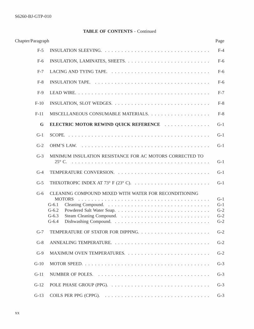
TABLE OF CONTENTS - Continued
Chapter/Paragraph Page
F-5 INSULATION SLEEVING. . . . . . . . . . . . . . . . . . . . . . . . . . . . . . . . . F-4
F-6 INSULATION, LAMINATES, SHEETS. . . . . . . . . . . . . . . . . . . . . . . . . . F-6
F-7 LACING AND TYING TAPE. . . . . . . . . . . . . . . . . . . . . . . . . . . . . . . F-6
F-8 INSULATION TAPE. . . . . . . . . . . . . . . . . . . . . . . . . . . . . . . . . . . . F-6
F-9 LEAD WIRE. . . . . . . . . . . . . . . . . . . . . . . . . . . . . . . . . . . . . . . . . F-7
F-10 INSULATION, SLOT WEDGES. . . . . . . . . . . . . . . . . . . . . . . . . . . . . . F-8
F-11 MISCELLANEOUS CONSUMABLE MATERIALS. . . . . . . . . . . . . . . . . . . F-8
G ELECTRIC MOTOR REWIND QUICK REFERENCE . . . . . . . . . . . . . . G-1
G-1 SCOPE. . . . . . . . . . . . . . . . . . . . . . . . . . . . . . . . . . . . . . . . . . . . G-1
G-2 OHM’S LAW. . . . . . . . . . . . . . . . . . . . . . . . . . . . . . . . . . . . . . . . G-1
G-3 MINIMUM INSULATION RESISTANCE FOR AC MOTORS CORRECTED TO25° C. . . . . . . . . . . . . . . . . . . . . . . . . . . . . . . . . . . . . . . . . . . G-1
G-4 TEMPERATURE CONVERSION. . . . . . . . . . . . . . . . . . . . . . . . . . . . . G-1
G-5 THIXOTROPIC INDEX AT 73° F (23° C). . . . . . . . . . . . . . . . . . . . . . . . G-1
G-6 CLEANING COMPOUND MIXED WITH WATER FOR RECONDITIONINGMOTORS . . . . . . . . . . . . . . . . . . . . . . . . . . . . . . . . . . . . . . . . G-1
G-6.1 Cleaning Compound. . . . . . . . . . . . . . . . . . . . . . . . . . . . . . . . G-1G-6.2 Powdered Salt Water Soap. . . . . . . . . . . . . . . . . . . . . . . . . . . . . G-2G-6.3 Steam Cleaning Compound. . . . . . . . . . . . . . . . . . . . . . . . . . . . G-2G-6.4 Dishwashing Compound. . . . . . . . . . . . . . . . . . . . . . . . . . . . . . G-2
G-7 TEMPERATURE OF STATOR FOR DIPPING. . . . . . . . . . . . . . . . . . . . . . G-2
G-8 ANNEALING TEMPERATURE. . . . . . . . . . . . . . . . . . . . . . . . . . . . . . G-2
G-9 MAXIMUM OVEN TEMPERATURES. . . . . . . . . . . . . . . . . . . . . . . . . . G-2
G-10 MOTOR SPEED. . . . . . . . . . . . . . . . . . . . . . . . . . . . . . . . . . . . . . . G-3
G-11 NUMBER OF POLES. . . . . . . . . . . . . . . . . . . . . . . . . . . . . . . . . . . G-3
G-12 POLE PHASE GROUP (PPG). . . . . . . . . . . . . . . . . . . . . . . . . . . . . . . G-3
G-13 COILS PER PPG (CPPG). . . . . . . . . . . . . . . . . . . . . . . . . . . . . . . . . G-3
S6260-BJ-GTP-010
xx
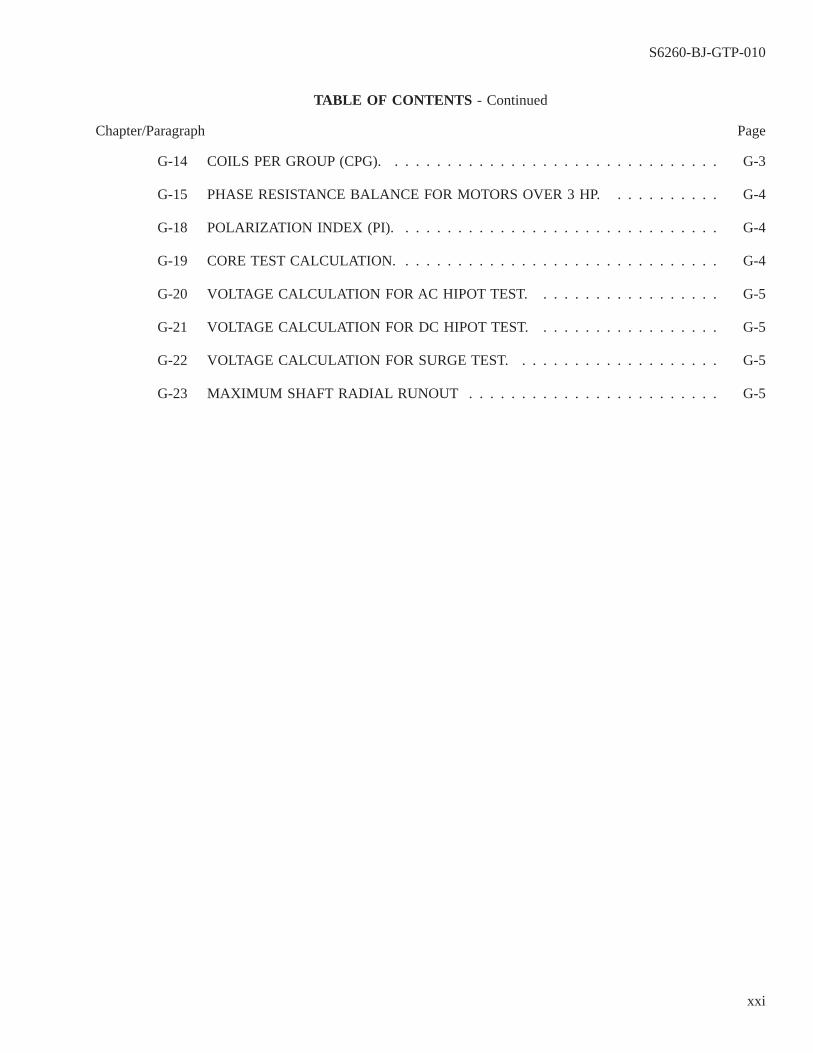
TABLE OF CONTENTS - Continued
Chapter/Paragraph Page
G-14 COILS PER GROUP (CPG). . . . . . . . . . . . . . . . . . . . . . . . . . . . . . . . G-3
G-15 PHASE RESISTANCE BALANCE FOR MOTORS OVER 3 HP. . . . . . . . . . . G-4
G-18 POLARIZATION INDEX (PI). . . . . . . . . . . . . . . . . . . . . . . . . . . . . . . G-4
G-19 CORE TEST CALCULATION. . . . . . . . . . . . . . . . . . . . . . . . . . . . . . . G-4
G-20 VOLTAGE CALCULATION FOR AC HIPOT TEST. . . . . . . . . . . . . . . . . . G-5
G-21 VOLTAGE CALCULATION FOR DC HIPOT TEST. . . . . . . . . . . . . . . . . . G-5
G-22 VOLTAGE CALCULATION FOR SURGE TEST. . . . . . . . . . . . . . . . . . . . G-5
G-23 MAXIMUM SHAFT RADIAL RUNOUT . . . . . . . . . . . . . . . . . . . . . . . . G-5
S6260-BJ-GTP-010
xxi
LIST OF TABLES
Table Title Page
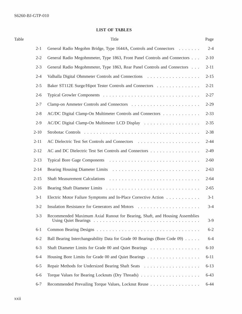
2-1 General Radio Megohm Bridge, Type 1644A, Controls and Connectors . . . . . . . 2-4
2-2 General Radio Megohmmeter, Type 1863, Front Panel Controls and Connectors . . . 2-10
2-3 General Radio Megohmmeter, Type 1863, Rear Panel Controls and Connectors . . . 2-11
2-4 Valhalla Digital Ohmmeter Controls and Connections . . . . . . . . . . . . . . . . . 2-15
2-5 Baker ST112E Surge/Hipot Tester Controls and Connectors . . . . . . . . . . . . . . 2-21
2-6 Typical Growler Components . . . . . . . . . . . . . . . . . . . . . . . . . . . . . . . 2-27
2-7 Clamp-on Ammeter Controls and Connectors . . . . . . . . . . . . . . . . . . . . . . 2-29
2-8 AC/DC Digital Clamp-On Multimeter Controls and Connectors . . . . . . . . . . . . 2-33
2-9 AC/DC Digital Clamp-On Multimeter LCD Display . . . . . . . . . . . . . . . . . . 2-35
2-10 Strobotac Controls . . . . . . . . . . . . . . . . . . . . . . . . . . . . . . . . . . . . . 2-38
2-11 AC Dielectric Test Set Controls and Connectors . . . . . . . . . . . . . . . . . . . . 2-44
2-12 AC and DC Dielectric Test Set Controls and Connectors . . . . . . . . . . . . . . . . 2-49
2-13 Typical Bore Gage Components . . . . . . . . . . . . . . . . . . . . . . . . . . . . . 2-60
2-14 Bearing Housing Diameter Limits . . . . . . . . . . . . . . . . . . . . . . . . . . . . 2-63
2-15 Shaft Measurement Calculations . . . . . . . . . . . . . . . . . . . . . . . . . . . . . 2-64
2-16 Bearing Shaft Diameter Limits . . . . . . . . . . . . . . . . . . . . . . . . . . . . . . 2-65
3-1 Electric Motor Failure Symptoms and In-Place Corrective Action . . . . . . . . . . . 3-1
3-2 Insulation Resistance for Generators and Motors . . . . . . . . . . . . . . . . . . . . 3-4
3-3 Recommended Maximum Axial Runout for Bearing, Shaft, and Housing AssembliesUsing Quiet Bearings . . . . . . . . . . . . . . . . . . . . . . . . . . . . . . . . . . 3-9
6-1 Common Bearing Designs . . . . . . . . . . . . . . . . . . . . . . . . . . . . . . . . . 6-2
6-2 Ball Bearing Interchangeability Data for Grade 00 Bearings (Bore Code 09) . . . . . 6-4
6-3 Shaft Diameter Limits for Grade 00 and Quiet Bearings . . . . . . . . . . . . . . . . 6-10
6-4 Housing Bore Limits for Grade 00 and Quiet Bearings . . . . . . . . . . . . . . . . . 6-11
6-5 Repair Methods for Undersized Bearing Shaft Seats . . . . . . . . . . . . . . . . . . 6-13
6-6 Torque Values for Bearing Locknuts (Dry Threads) . . . . . . . . . . . . . . . . . . . 6-43
6-7 Recommended Prevailing Torque Values, Locknut Reuse . . . . . . . . . . . . . . . . 6-44
S6260-BJ-GTP-010
xxii
LIST OF TABLES - Continued
Table Title Page
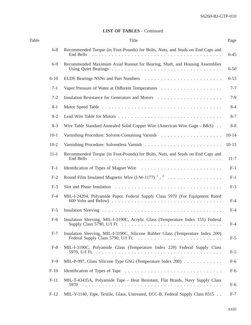
6-8 Recommended Torque (in Foot-Pounds) for Bolts, Nuts, and Studs on End Caps andEnd Bells . . . . . . . . . . . . . . . . . . . . . . . . . . . . . . . . . . . . . . . . 6-45
6-9 Recommended Maximum Axial Runout for Bearing, Shaft, and Housing AssembliesUsing Quiet Bearings . . . . . . . . . . . . . . . . . . . . . . . . . . . . . . . . . . 6-50
6-10 ELDS Bearings NSNs and Part Numbers . . . . . . . . . . . . . . . . . . . . . . . . 6-53
7-1 Vapor Pressure of Water at Different Temperatures . . . . . . . . . . . . . . . . . . . 7-7
7-2 Insulation Resistance for Generators and Motors . . . . . . . . . . . . . . . . . . . . 7-9
8-1 Motor Speed Table . . . . . . . . . . . . . . . . . . . . . . . . . . . . . . . . . . . . . 8-4
8-2 Lead Wire Table for Motors . . . . . . . . . . . . . . . . . . . . . . . . . . . . . . . . 8-7
8-3 Wire Table Standard Annealed Solid Copper Wire (American Wire Gage - B&S) . . 8-8
10-1 Varnishing Procedure: Solvent-Containing Varnish . . . . . . . . . . . . . . . . . . . 10-14
10-2 Varnishing Procedure: Solventless Varnish . . . . . . . . . . . . . . . . . . . . . . . . 10-15
11-1 Recommended Torque (in Foot-Pounds) for Bolts, Nuts, and Studs on End Caps andEnd Bells . . . . . . . . . . . . . . . . . . . . . . . . . . . . . . . . . . . . . . . . 11-7
F-1 Identification of Types of Magnet Wire . . . . . . . . . . . . . . . . . . . . . . . . . F-1
F-2 Round Film Insulated Magnetic Wire (J-W-1177) 1 , 2 . . . . . . . . . . . . . . . . . F-1
F-3 Slot and Phase Insulation . . . . . . . . . . . . . . . . . . . . . . . . . . . . . . . . . F-3
F-4 MIL-I-24204, Polyamide Paper, Federal Supply Class 5970 (For Equipment Rated600 Volts and Below) . . . . . . . . . . . . . . . . . . . . . . . . . . . . . . . . . . F-4
F-5 Insulation Sleeving . . . . . . . . . . . . . . . . . . . . . . . . . . . . . . . . . . . . . F-4
F-6 Insulation Sleeving, MIL-I-3190C, Acrylic Glass (Temperature Index 155) FederalSupply Class 5790, U/I Ft. . . . . . . . . . . . . . . . . . . . . . . . . . . . . . . . F-4
F-7 Insulation Sleeving, MIL-I-3190C, Silicone Rubber Glass (Temperature Index 200)Federal Supply Class 5790, U/I Ft. . . . . . . . . . . . . . . . . . . . . . . . . . . F-5
F-8 MIL-I-3190C, Polyamide Glass (Temperature Index 220) Federal Supply Class5970, U/I Ft. . . . . . . . . . . . . . . . . . . . . . . . . . . . . . . . . . . . . . . . F-5
F-9 MIL-P-997, Glass Silicone Type GSG (Temperature Index 200) . . . . . . . . . . . . F-6
F-10 Identification of Types of Tape . . . . . . . . . . . . . . . . . . . . . . . . . . . . . . F-6
F-11 MIL-T-43435A, Polyamide Tape - Heat Resistant, Flat Braids, Navy Supply Class5970 . . . . . . . . . . . . . . . . . . . . . . . . . . . . . . . . . . . . . . . . . . . F-6
F-12 MIL-Y-1140, Tape, Textile, Glass, Untreated, ECC-B, Federal Supply Class 8315 . . F-7
S6260-BJ-GTP-010
xxiii
LIST OF TABLES - Continued
Table Title Page
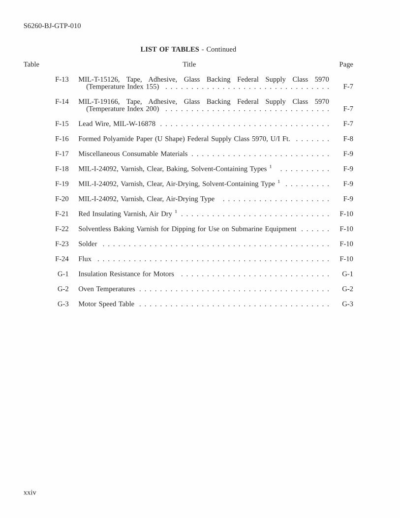
F-13 MIL-T-15126, Tape, Adhesive, Glass Backing Federal Supply Class 5970(Temperature Index 155) . . . . . . . . . . . . . . . . . . . . . . . . . . . . . . . . F-7
F-14 MIL-T-19166, Tape, Adhesive, Glass Backing Federal Supply Class 5970(Temperature Index 200) . . . . . . . . . . . . . . . . . . . . . . . . . . . . . . . . F-7
F-15 Lead Wire, MIL-W-16878 . . . . . . . . . . . . . . . . . . . . . . . . . . . . . . . . . F-7
F-16 Formed Polyamide Paper (U Shape) Federal Supply Class 5970, U/I Ft. . . . . . . . F-8
F-17 Miscellaneous Consumable Materials . . . . . . . . . . . . . . . . . . . . . . . . . . . F-9
F-18 MIL-I-24092, Varnish, Clear, Baking, Solvent-Containing Types 1 . . . . . . . . . . F-9
F-19 MIL-I-24092, Varnish, Clear, Air-Drying, Solvent-Containing Type 1 . . . . . . . . . F-9
F-20 MIL-I-24092, Varnish, Clear, Air-Drying Type . . . . . . . . . . . . . . . . . . . . . F-9
F-21 Red Insulating Varnish, Air Dry 1 . . . . . . . . . . . . . . . . . . . . . . . . . . . . . F-10
F-22 Solventless Baking Varnish for Dipping for Use on Submarine Equipment . . . . . . F-10
F-23 Solder . . . . . . . . . . . . . . . . . . . . . . . . . . . . . . . . . . . . . . . . . . . . F-10
F-24 Flux . . . . . . . . . . . . . . . . . . . . . . . . . . . . . . . . . . . . . . . . . . . . . F-10
G-1 Insulation Resistance for Motors . . . . . . . . . . . . . . . . . . . . . . . . . . . . . G-1
G-2 Oven Temperatures . . . . . . . . . . . . . . . . . . . . . . . . . . . . . . . . . . . . . G-2
G-3 Motor Speed Table . . . . . . . . . . . . . . . . . . . . . . . . . . . . . . . . . . . . . G-3
S6260-BJ-GTP-010
xxiv
LIST OF ILLUSTRATIONS
Figure Title Page
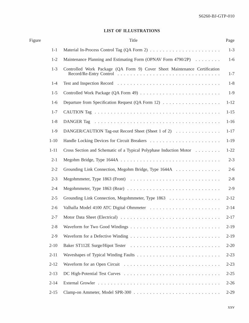
1-1 Material In-Process Control Tag (QA Form 2) . . . . . . . . . . . . . . . . . . . . . . 1-3
1-2 Maintenance Planning and Estimating Form (OPNAV Form 4790/2P) . . . . . . . . 1-6
1-3 Controlled Work Package (QA Form 9) Cover Sheet Maintenance CertificationRecord/Re-Entry Control . . . . . . . . . . . . . . . . . . . . . . . . . . . . . . . . 1-7
1-4 Test and Inspection Record . . . . . . . . . . . . . . . . . . . . . . . . . . . . . . . . 1-8
1-5 Controlled Work Package (QA Form 49) . . . . . . . . . . . . . . . . . . . . . . . . . 1-9
1-6 Departure from Specification Request (QA Form 12) . . . . . . . . . . . . . . . . . . 1-12
1-7 CAUTION Tag . . . . . . . . . . . . . . . . . . . . . . . . . . . . . . . . . . . . . . . 1-15
1-8 DANGER Tag . . . . . . . . . . . . . . . . . . . . . . . . . . . . . . . . . . . . . . . 1-16
1-9 DANGER/CAUTION Tag-out Record Sheet (Sheet 1 of 2) . . . . . . . . . . . . . . 1-17
1-10 Handle Locking Devices for Circuit Breakers . . . . . . . . . . . . . . . . . . . . . . 1-19
1-11 Cross Section and Schematic of a Typical Polyphase Induction Motor . . . . . . . . 1-22
2-1 Megohm Bridge, Type 1644A . . . . . . . . . . . . . . . . . . . . . . . . . . . . . . . 2-3
2-2 Grounding Link Connection, Megohm Bridge, Type 1644A . . . . . . . . . . . . . . 2-6
2-3 Megohmmeter, Type 1863 (Front) . . . . . . . . . . . . . . . . . . . . . . . . . . . . 2-8
2-4 Megohmmeter, Type 1863 (Rear) . . . . . . . . . . . . . . . . . . . . . . . . . . . . . 2-9
2-5 Grounding Link Connection, Megohmmeter, Type 1863 . . . . . . . . . . . . . . . . 2-12
2-6 Valhalla Model 4100 ATC Digital Ohmmeter . . . . . . . . . . . . . . . . . . . . . . 2-14
2-7 Motor Data Sheet (Electrical) . . . . . . . . . . . . . . . . . . . . . . . . . . . . . . . 2-17
2-8 Waveform for Two Good Windings . . . . . . . . . . . . . . . . . . . . . . . . . . . . 2-19
2-9 Waveform for a Defective Winding . . . . . . . . . . . . . . . . . . . . . . . . . . . . 2-19
2-10 Baker ST112E Surge/Hipot Tester . . . . . . . . . . . . . . . . . . . . . . . . . . . . 2-20
2-11 Waveshapes of Typical Winding Faults . . . . . . . . . . . . . . . . . . . . . . . . . . 2-23
2-12 Waveform for an Open Circuit . . . . . . . . . . . . . . . . . . . . . . . . . . . . . . 2-23
2-13 DC High-Potential Test Curves . . . . . . . . . . . . . . . . . . . . . . . . . . . . . . 2-25
2-14 External Growler . . . . . . . . . . . . . . . . . . . . . . . . . . . . . . . . . . . . . . 2-26
2-15 Clamp-on Ammeter, Model SPR-300 . . . . . . . . . . . . . . . . . . . . . . . . . . . 2-29
S6260-BJ-GTP-010
xxv

LIST OF ILLUSTRATIONS - Continued
Figure Title Page
2-16 AC/DC Digital Clamp-On Multimeter . . . . . . . . . . . . . . . . . . . . . . . . . . 2-33
2-17 Strobotac Type 1531-AB . . . . . . . . . . . . . . . . . . . . . . . . . . . . . . . . . 2-37
2-18 Insulation Resistance-Temperature Nomograph . . . . . . . . . . . . . . . . . . . . . 2-40
2-19 AC Dielectric Test Set Front Panel Controls . . . . . . . . . . . . . . . . . . . . . . . 2-43
2-20 AC and DC Dielectric Test Set Front Panel Controls . . . . . . . . . . . . . . . . . . 2-49
2-21 Dial Indicator (Typical) . . . . . . . . . . . . . . . . . . . . . . . . . . . . . . . . . . 2-53
2-22 Shaft Runout Indication . . . . . . . . . . . . . . . . . . . . . . . . . . . . . . . . . . 2-54
2-23 Motor Data Sheet (Mechanical) . . . . . . . . . . . . . . . . . . . . . . . . . . . . . . 2-56
2-24 Measuring Bearing Inner Rings . . . . . . . . . . . . . . . . . . . . . . . . . . . . . . 2-57
2-25 Typical Bore Gage . . . . . . . . . . . . . . . . . . . . . . . . . . . . . . . . . . . . . 2-59
2-26 Typical Snap Gage . . . . . . . . . . . . . . . . . . . . . . . . . . . . . . . . . . . . . 2-62
3-1 Motor Data Sheet (Electrical) . . . . . . . . . . . . . . . . . . . . . . . . . . . . . . . 3-2
3-2 Typical Motor Data Sheet (Mechanical) . . . . . . . . . . . . . . . . . . . . . . . . . 3-7
3-3 Checking Motor Shaft Movement . . . . . . . . . . . . . . . . . . . . . . . . . . . . . 3-8
3-4 Measuring Bearing Inner Rings . . . . . . . . . . . . . . . . . . . . . . . . . . . . . . 3-10
4-1 Use of Wire Rope Clamp Fittings . . . . . . . . . . . . . . . . . . . . . . . . . . . . 4-5
4-2 Wire Rope Fittings . . . . . . . . . . . . . . . . . . . . . . . . . . . . . . . . . . . . . 4-6
4-3 Mousing Wire Rope Fittings . . . . . . . . . . . . . . . . . . . . . . . . . . . . . . . 4-8
4-4 Types of Chain Hoists . . . . . . . . . . . . . . . . . . . . . . . . . . . . . . . . . . . 4-9
4-5 Single-Drum Hand Winch . . . . . . . . . . . . . . . . . . . . . . . . . . . . . . . . . 4-10
4-6 Two-Legged Bridle Sling . . . . . . . . . . . . . . . . . . . . . . . . . . . . . . . . . 4-11
4-7 Two-Legged Bridle Sling Lifting Motor with Safety Hook . . . . . . . . . . . . . . . 4-12
4-8 Yard and Stay Method . . . . . . . . . . . . . . . . . . . . . . . . . . . . . . . . . . . 4-15
4-9 Shaft Protection Fixture . . . . . . . . . . . . . . . . . . . . . . . . . . . . . . . . . . 4-17
4-10 Typical Rotor Sling . . . . . . . . . . . . . . . . . . . . . . . . . . . . . . . . . . . . 4-18
5-1 Motor Data Sheet (Mechanical) . . . . . . . . . . . . . . . . . . . . . . . . . . . . . . 5-3
S6260-BJ-GTP-010
xxvi

LIST OF ILLUSTRATIONS - Continued
Figure Title Page
5-2 Checking Motor Shaft Movement . . . . . . . . . . . . . . . . . . . . . . . . . . . . . 5-4
5-3 Matchmarking . . . . . . . . . . . . . . . . . . . . . . . . . . . . . . . . . . . . . . . 5-5
5-4 End Bell Disassembly . . . . . . . . . . . . . . . . . . . . . . . . . . . . . . . . . . . 5-8
5-5 Installing Packing to Support Rotor . . . . . . . . . . . . . . . . . . . . . . . . . . . 5-9
5-6 Shaft Runout Indication . . . . . . . . . . . . . . . . . . . . . . . . . . . . . . . . . . 5-10
5-7 Removing Bearing Locknut . . . . . . . . . . . . . . . . . . . . . . . . . . . . . . . . 5-11
5-8 Typical Locknut Wrench and Table of Dimensions . . . . . . . . . . . . . . . . . . . 5-13
5-9 Motor Data Sheet (Electrical) . . . . . . . . . . . . . . . . . . . . . . . . . . . . . . . 5-16
6-1 Mounting Methods for Vertically Mounted Ball Bearings . . . . . . . . . . . . . . . 6-7
6-2 Mounting Methods for Horizontally Mounted Ball Bearings . . . . . . . . . . . . . . 6-9
6-3 Typical Locknut Wrench and Table of Dimensions . . . . . . . . . . . . . . . . . . . 6-27
6-4 Application of Mounting and Dismounting Forces to Tightly Fitted Bearing Rings . 6-30
6-5 Arbor Press Method of Removing Bearings . . . . . . . . . . . . . . . . . . . . . . . 6-31
6-6 Bearing Puller Removal Using Split Puller Attachment and Shaft Protector . . . . . 6-32
6-7 Split Spacer Allows Use of Cover to Remove Inner Ring . . . . . . . . . . . . . . . 6-34
6-8 Using a High-Speed Grinder to Cut Outer Ring . . . . . . . . . . . . . . . . . . . . . 6-36
6-9 Cutting Inner Ring with High-Speed Grinder . . . . . . . . . . . . . . . . . . . . . . 6-37
6-10 Using Chisel to Remove Inner Ring . . . . . . . . . . . . . . . . . . . . . . . . . . . 6-37
6-11 Motor Data Sheet (Mechanical) . . . . . . . . . . . . . . . . . . . . . . . . . . . . . . 6-39
6-12 Measuring Shaft Shoulder Runout . . . . . . . . . . . . . . . . . . . . . . . . . . . . 6-40
6-13 Pressing Bearings on Shaft with an Arbor Press . . . . . . . . . . . . . . . . . . . . . 6-40
6-14 Effect of Dirt in Mounting Bearings . . . . . . . . . . . . . . . . . . . . . . . . . . . 6-41
6-15 Conventional Locknut and Lockwasher . . . . . . . . . . . . . . . . . . . . . . . . . 6-42
6-16 Self-Locking Locknut . . . . . . . . . . . . . . . . . . . . . . . . . . . . . . . . . . . 6-42
6-17 Hammer Mounting (Use in Emergencies Only) . . . . . . . . . . . . . . . . . . . . . 6-46
6-18 Duplex Bearing Arrangements Showing Relation of the Outer Ring Faces . . . . . . 6-47
S6260-BJ-GTP-010
xxvii

LIST OF ILLUSTRATIONS - Continued
Figure Title Page
6-19 Bearing Ring Radial Runout Alignment of Precision Bearing Pairs . . . . . . . . . . 6-47
6-20 Mounting of Duplex Bearing (DB Mount Shown) . . . . . . . . . . . . . . . . . . . 6-48
6-21 Measurement Location for Determining Bearing Axial Runout and Shaft RadialRunout . . . . . . . . . . . . . . . . . . . . . . . . . . . . . . . . . . . . . . . . . . 6-51
6-22 Measurement Location for Determining Face and Rim Runouts . . . . . . . . . . . . 6-52
8-1 Motor Repair Identification Sheet . . . . . . . . . . . . . . . . . . . . . . . . . . . . . 8-3
8-2 Portions of Distributed and Basket Windings . . . . . . . . . . . . . . . . . . . . . . 8-6
8-3 Removing Slot Wedges . . . . . . . . . . . . . . . . . . . . . . . . . . . . . . . . . . 8-11
8-4 Cutting Off End Turns . . . . . . . . . . . . . . . . . . . . . . . . . . . . . . . . . . . 8-12
8-5 Coil Puller Setup for Electrical Heating . . . . . . . . . . . . . . . . . . . . . . . . . 8-15
9-1 Motor Repair Identification Sheet . . . . . . . . . . . . . . . . . . . . . . . . . . . . . 9-3
9-2 Winding Head and Wire Guides . . . . . . . . . . . . . . . . . . . . . . . . . . . . . 9-5
9-3 Tying of Coils on Winding Machine . . . . . . . . . . . . . . . . . . . . . . . . . . . 9-6
9-4 Tape Applied to Coils . . . . . . . . . . . . . . . . . . . . . . . . . . . . . . . . . . . 9-8
9-5 Cuffing of Slot Cell Material . . . . . . . . . . . . . . . . . . . . . . . . . . . . . . . 9-10
9-6 Method of Fitting Slot Insulation . . . . . . . . . . . . . . . . . . . . . . . . . . . . . 9-11
9-7 Slot Cell Width Precut with Feeder Paper . . . . . . . . . . . . . . . . . . . . . . . . 9-11
9-8 Lengths of Slot Insulator Pieces . . . . . . . . . . . . . . . . . . . . . . . . . . . . . 9-12
9-9 Folding Slot Insulation Cuffs . . . . . . . . . . . . . . . . . . . . . . . . . . . . . . . 9-12
9-10 Fitting the Pieces of a Slot Insulator . . . . . . . . . . . . . . . . . . . . . . . . . . . 9-13
9-11 Slot Insulation Fitting for Feeder Paper . . . . . . . . . . . . . . . . . . . . . . . . . 9-13
9-12 Completed Stator with Tools Used . . . . . . . . . . . . . . . . . . . . . . . . . . . . 9-14
9-13 Partially Completed Stator in Stator Holder . . . . . . . . . . . . . . . . . . . . . . . 9-15
9-14 Placing of Coil Sides from Slot Edges . . . . . . . . . . . . . . . . . . . . . . . . . . 9-16
9-15 Protection of Coil Sides from Slot Edges . . . . . . . . . . . . . . . . . . . . . . . . 9-17
9-16 Temporary Wedge Holding Down Coil Sides . . . . . . . . . . . . . . . . . . . . . . 9-18
9-17 Cutting of Slot Cell Material . . . . . . . . . . . . . . . . . . . . . . . . . . . . . . . 9-19
S6260-BJ-GTP-010
xxviii

LIST OF ILLUSTRATIONS - Continued
Figure Title Page
9-18 Closing Slots . . . . . . . . . . . . . . . . . . . . . . . . . . . . . . . . . . . . . . . . 9-20
9-19 Placement of Phase Material . . . . . . . . . . . . . . . . . . . . . . . . . . . . . . . 9-21
9-20 Trimming of Phase Material . . . . . . . . . . . . . . . . . . . . . . . . . . . . . . . . 9-22
9-21 Heat Sinks in Place and Placement of Sleeving . . . . . . . . . . . . . . . . . . . . . 9-24
9-22 Lacing of End Turns and Coil Connections . . . . . . . . . . . . . . . . . . . . . . . 9-25
9-23 External Connection Prior to Soldering . . . . . . . . . . . . . . . . . . . . . . . . . 9-26
10-1 Varnish Viscosity Chart, No. 2 Zahn Cup and No. 1 Demmler Cup . . . . . . . . . . 10-10
11-1 Motor Data Sheet (Electrical) . . . . . . . . . . . . . . . . . . . . . . . . . . . . . . . 11-3
11-2 Motor Data Sheet (Mechanical) . . . . . . . . . . . . . . . . . . . . . . . . . . . . . . 11-5
D-1 Single- and Two-Layer Windings . . . . . . . . . . . . . . . . . . . . . . . . . . . . . D-3
D-2 Semi-Closed and Open Stator and Rotor Slots . . . . . . . . . . . . . . . . . . . . . . D-4
D-3 Chain and Distributed Windings . . . . . . . . . . . . . . . . . . . . . . . . . . . . . D-5
D-4 Full-Pitch and Fractional Pitch Windings . . . . . . . . . . . . . . . . . . . . . . . . D-6
D-5 Three-Phase, Four-Pole Winding . . . . . . . . . . . . . . . . . . . . . . . . . . . . . D-7
D-6 Three-Phase Winding . . . . . . . . . . . . . . . . . . . . . . . . . . . . . . . . . . . D-8
D-7 Wye Connection . . . . . . . . . . . . . . . . . . . . . . . . . . . . . . . . . . . . . . D-9
D-8 Delta Connection . . . . . . . . . . . . . . . . . . . . . . . . . . . . . . . . . . . . . . D-10
D-9 Four-Pole, Three-Phase, Series Wye Connection Diagram . . . . . . . . . . . . . . . D-11
D-10 Four-Pole, Three-Phase, Two-Parallel Wye Connection Diagram . . . . . . . . . . . D-12
D-11 Four-Pole, Three-Phase, Series Delta Connection Diagram . . . . . . . . . . . . . . . D-13
D-12 Four-Pole, Three-Phase, Two-Parallel Delta Connection Diagram . . . . . . . . . . . D-14
S6260-BJ-GTP-010
xxix
SAFETY SUMMARY
This publication describes physical and chemical processes which may require the use of chemicals, sol-vents, paints, or other commercially available material. The user of this publication should obtain the materialsafety data sheets (Occupational Safety and Health Act (OSHA) Form 20 or equivalent) from the manufacturersor suppliers of materials to be used. The user must become completely familiar with the manufacturer/supplierinformation and adhere to the procedures, recommendations, warnings, and cautions of the manufacturer/supplierfor the safe use, handling, storage, and disposal of these materials. The following are general safety precautionsand instructions that people must understand and apply during many phases of operation and maintenance toensure personal safety and health and the protection of DOD property. Portions of this may be repeated elsewherein this publication for emphasis.
DANGER, WARNING, AND CAUTION STATEMENTS. DANGER, WARNING, and CAUTION state-ments have been strategically placed throughout this text prior to operating or maintenance procedures, practices,or conditions considered essential to the protection of personnel (DANGER and WARNING) or equipment andproperty (CAUTION). A DANGER, WARNING, or CAUTION statement will apply each time the related stepis repeated. Prior to starting any task, the DANGER, WARNING, or CAUTION statements included in the textfor that task will be reviewed and understood.
ELECTRIC SHOCK. People working around energized electric circuits and equipment must alwaysobserve safety precautions. Injury may result from electric shock. Short circuits can be caused by accidentallyplacing or dropping a metal tool, flashlight case, or other conducting article across an energized line. These shortcircuits can cause an arc or fire on even relatively low voltage circuits and may result in extensive damage toequipment and serious injury to personnel. For additional information, refer to NAVSEA S9086-KC-STM-010/CH 300.
CAUSE OF ELECTRIC SHOCK. Current rather than voltage is the measure of shock intensity. The pas-sage of even a very small current through a vital part of the human body can cause death. The ability of a cir-cuit to produce a fatal current is dependent upon the resistance of the body, contact conditions, the path throughthe body, etc. Fatalities have occurred from circuits with voltages as low 30 volts. For additional information,refer to NAVSEA S9086-KC-STM-010/CH 300.
RESCUE FROM ELECTRIC SHOCK. The rescue of electric shock victims depends on their promptremoval from the source of shock and the administration of first aid. Personnel trained in safe removal of a vic-tim from a source of electric shock and cardiopulmonary resuscitation (CPR) procedures should perform thisemergency procedure. For additional information, refer to NAVSEA S9086-KC-STM-010/CH 300.
INDIVIDUAL RESPONSIBILITY. Individuals have a responsibility, not only to themselves but also totheir shipmates, to always be alert to detect and report unsafe work practices and unsafe conditions. Each indi-vidual must
1. Observe all posted operating instructions and safety precautions.
2. Report any condition, equipment, or material that is believed to be unsafe.
3. Caution others to observe safety precautions.
4. Report to the supervisor any injury obtained in the course of their work.
S6260-BJ-GTP-010
xxx
SAFETY SUMMARY - Continued
5. Exercise caution in the event of an emergency, where deranged equipment or abnormal operating con-ditions could produce additional, unseen hazards.
SHIPBOARD ELECTRICAL SYSTEMS.
EQUIPMENT GROUNDING AND SYSTEM GROUNDING. The word grounding is frequently used inac electrical power systems for referring to both equipment grounding and system grounding.
Equipment grounding is an important safety measure. Equipment grounding intentionally connects thenon-current-carrying conductive parts of electrical equipment to ground through a low-resistance path. If an ener-gized electrical conductor contacts the enclosure due to a fault or mechanical damage, the equipment ground pro-vides the lowest impedance path of electrical current to ground, shunting the current away from a possible humancontact. Electrical power systems can be classified by the nature of the connection between the neutral of thepower system and ground. The system is said to be ungrounded when the electrical system neutral or phase con-ductors are not intentionally connected to ground expect through potential measuring devices or other very high-impedance devices. Navy ships use an ungrounded system. Electric utility service for house wiring ashore usesa grounded neutral system so that a fault will produce a high current and quickly trip the circuit breaker or blowthe fuse. For additional information, refer to NAVSEA S9086-KC-STM-010/CH 300.
GENERAL ELECTRICAL SAFETY PRECAUTIONS FOR EQUIPMENT MAINTENANCE.
EQUIPMENT MAINTENANCE. Safety from electrical hazards during any form of maintenance work canbest be ensured by completely deenergizing equipment. Follow the tag-out instructions for working on deener-gized equipment in Chapter 1 of this manual and NAVSEA S9086-KC-STM-010/CH 300. When it is necessaryto work on energized equipment, the requirements of NAVSEA S9086-KC-STM-010/CH 300, paragraph300-2.5, shall be carefully adhered to.
Equipment maintenance covers both preventive and corrective maintenance of electrical equipment andincludes any or all of the following work:
Testing
Calibrating
Taking measurements
Troubleshooting
Repairing
Assembling
Disassembling
Making adjustments
GENERAL SAFETY PRECAUTIONS.
S6260-BJ-GTP-010
xxxi

SAFETY SUMMARY - Continued
1. Do not touch a conductor, until it is tested, to be sure it is deenergized.
2. Obey all warning signs; read equipment warning labels before use.
3. Do not energize any equipment that is tagged out. Properly clear the tag first.
4. Use authorized equipment to perform maintenance work.
5. Close all fuse boxes, junction boxes, switch boxes, and wiring accessories.
6. Never operate a switch with the other hand on a metal surface.
7. Never use outlets that appear to be burnt.
8. When using a metal-cased tool, ensure it is equipped with a three conductor cord, and three-prongedplug. Verify that the ground prong extends beyond the power blade of the plug.
9. Wear rubber gloves when using metal-cased portable electrical equipment, or when using electrichandheld portable tools in hazardous conditions, such as wet decks and bilge areas. Leather glovesshall be worn over rubber gloves when the work being done could damage the rubber gloves.
10. Do not use equipment with worn or damaged cords, or crushed or damaged plugs.
11. Check the portable electrical equipment has been inspected and has a current inspection label affixed.
12. Only use electric equipment in explosive atmospheres if the equipment is approved for such use(explosion proof).
13. Do not allow cords to run over sharp objects, chemicals, or hot surfaces.
14. Do not join more than two 25-foot extension cords together. Single-length extension cords up to100-foot are permissible.
15. Use a voltmeter or voltage tester to ensure that equipment or circuits are deenergized.
For additional information, refer to NAVSEA S9086-KC-STM-010/CH 300.
WORK ON DEENERGIZED EQUIPMENT.
EQUIPMENT TAG-OUT PROCEDURES. Safety from electrical hazards can best be ensured by com-pletely deenergizing equipment on which work is to be done. Always deenergize electrical equipment by open-ing the power supply circuit breaker or switch, or removing the appropriate fuse, and use the equipment tag-outprocedure before continuing with work. For requirements concerning work on energized circuits or equip-ment, see NAVSEA S9086-KC-STM-010/CH 300, paragraph 300-2.5.
SAFETY-RELATED ITEMS. Refer to NAVSEA S9086-KC-STM-010/CH 300, table 300-2-1, for a list ofsafety-related items used for electrical and electronic maintenance and repair.
CHECKING FOR ENERGIZED CIRCUITS. Be sure electrical equipment is deenergized before workingon it. To verify a circuit is deenergized, first connect the leads of a voltmeter or voltage tester across the powersource terminals of a known energized circuit to ensure the device is working properly. Next, connect the leadsof the device across the power source terminals of the equipment under test and from each terminal to ground toverify it is deenergized. Recheck the voltmeter or voltage tester on the known energized circuit to ensure that thedevice is still working properly. For additional information, refer to NAVSEA S9086-KC-STM-010/CH 300.
S6260-BJ-GTP-010
xxxii
SAFETY SUMMARY - Continued
DISCHARGING DEENERGIZED CIRCUITS. The electrical charge retained by secured electrical equip-ment may be great enough to cause a severe shock. This danger must be considered before touching the termi-nals to an apparently deenergized equipment. Discharge the equipment to ground by momentarily connecting theterminal to ground using a short probe (see NAVSEA S9086-KC-STM-010/CH 300, table 300-2-1). Capacitorsand picture tubes can develop a charge after a period of time and may need to be shorted several times beforebeing fully discharged. For additional information, refer to NAVSEA S9086-KC-STM-010/CH 300.
WORKING ON ENERGIZED EQUIPMENT.
APPROVAL PROCEDURES. Electrical equipment is a source of great danger if not properly approached.The Commanding Officer is responsible for electrical safety. Energized electrical equipment shall not be disas-sembled nor undergo any maintenance without approval of such action by the Commanding Officer or, in hisabsence, the Command Duty Officer. The only exceptions to this policy are in those cases in which approvalinstructions issued by higher authority (equipment technical manuals, PMS, or an established troubleshootingprocedure) permit opening or inspecting equipments in the course of performing maintenance, routine testing,taking measurements, or making adjustments that require equipment to be energized. When external test pointsare provided on an equipment panel, testing with an instrument using these test points shall not be considered asworking on an energized equipment. For additional information, refer to NAVSEA S9086-KC-STM-010/CH 300.
ENERGIZED CIRCUIT WORKING PROCEDURES. When maintenance must be done on energized cir-cuits or equipment, the following precautions shall be observed in addition to the general precautions ofNAVSEA S9086-KC-STM-010/CH 300, paragraph 300-2.5. These precautions do not apply for circuits or equip-ment less than 30 volts:
1. Never work on energized electrical or electronic equipment by yourself have another person (safetyobserver) qualified in first aid for electrical shock present at all times. The safety observer should alsoknow which circuits and switches deenergize the equipment and will be given instructions to operatethe switch immediately if anything unforeseen happens.
2. Workers shall not wear wristwatches, rings, watch chains, metal articles, or loose clothing that mightaccidentally contact energized parts or throw some part of their bodies into contact with mechanical/electrical active components. Clothing and shoes shall be as dry as possible.
3. Insulate the deck or standing surface from ground by covering with insulating material. Rubber mator rubber blankets shall be used for this covering. If mats or blankets are not available, and the workmust be accomplished before the specified material is available, other suitable insulating materials aredry wood, dry canvas, dry phenolic material, or even several layers of heavy, dry paper. Be sure insu-lating material is dry, has no holes in it, and that no conducting materials are embedded in it. Coverenough area so that workers have adequate space to move about.
4. Use only one hand to do the work, if practical.
5. If the work being done permits, rubber gloves shall be worn on both hands; if not, a rubber glove shallbe worn on the one hand not used for handling tools.
6. A face shield or spectacles shall be worn during work on energized equipment, since a short circuitcould produce a high fault current capable of producing flying molten particles and intense heat.
7. Cover metal on hand-held tools with an electrical insulating material. One acceptable method is to use
S6260-BJ-GTP-010
xxxiii

SAFETY SUMMARY - Continued
two layers of rubber or vinyl plastic tape, half-lapped. Another method is to coat tools with Plastisol;see instructions in NSTM , Chapter 631, ″Preservation of Ships in Service.″ In an emergency, if timedoes not permit applying the foregoing materials, the tool handles and tool shafts may be covered withcambric sleeving, synthetic resin flexing tubing, or with insulation tubing removed from scrap of cer-tain kinds of electrical cable.
8. Take the following extra precautions when the nature of the work is particularly hazardous, such aswhen working in the interior of a switchboard or other cubical where exposed energized bus bars arein the vicinity of the work or the work actually requires contact by tools to the energized components:
a. Station personnel with communications, as necessary, so that the circuit or switchboard can bedeenergized immediately in an emergency.
b. Provide insulation barriers between the work and any energized metal parts adjacent to the workarea as practicable.
c. Erect barriers to keep unauthorized personnel out of the maintenance area. Erect barrier at a mini-mum distance of three feet from the energized electrical work site. Place a sign at the barrier thatstates: DANGER, Working on Energized Equipment, Unauthorized Personnel, Keep Out.
d. A nonconducting safety line or equivalent shall be attached to a safety harness or tied around thewaist in case the person performing the maintenance must be pulled from the work area. A persontending the other end of the safety line or equivalent shall be located at a safe distance outside thesafety barrier such that any inadvertent action (such as falling) would not jeopardize the persondoing the work.
9. While work is being done, a person trained m mouth-to-mouth resuscitation and cardiac massage shallbe immediately available in case of electrical shock.
FUSE REPLACEMENT. Fuses are safety devices and should be used as such. When a fuse blows, itshould be replaced with a fuse of the same related voltage and ampere capacity. Never replace with a highercurrent rating fuse or short out on a blown fuse. Use fuse pullers listed in NAVSEA S9086-KC-STM-010/CH300, table 300-2-1, to remove and replace fuses except where fuses are mounted in plug-type fuse holders (e.g.,on IC and FC switchboards). Remove these fuses by unscrewing the plugs.
SPECIAL PRECAUTIONS WHILE WORKING ON DAMAGED EQUIPMENT. A maximum degree ofalertness and care is required to work on damaged equipment. When working on electrical equipment or circuitsthat have been damaged and may be deranged internally to impose a possible personnel safety hazard, observeall electrical safety precautions in NAVSEA S9086-KC-STM-010/CH 300, paragraphs 300-2.3 and 300-2.4, andall precautions for maintenance on energized circuits in NAVSEA S9086-KC-STM-010/CH 300, paragraph 300-2.5, until it is verified that all portions of the circuit are deenergized. Equipment or circuits that are not operat-ing properly, but have not had a casualty, are probably not internally deranged and do not need to be consideredas work on damaged equipment.
PORTABLE ELECTRICAL EQUIPMENT.
GENERAL PRECAUTIONS FOR PORTABLE ELECTRICAL EQUIPMENT. Portable electrical equip-ment is a device that will be plugged into a shipboard isolation receptacle and operate with the ship’s electricalpower. Hazards associated with the use of portable power equipment include electrical shock, bruises, cuts, par-ticles in the eye, falls, and explosions. Safe practices in the use of this equipment will reduce or eliminate suchaccidents. Listed below are some of the general safety precautions that shall be observed when work requires theuse of portable electrical equipment. The use of portable electrical equipment can be potentially hazardous. Foradditional information, refer to NAVSEA S9086-KC-STM-010/CH 300.
S6260-BJ-GTP-010
xxxiv
SAFETY SUMMARY - Continued
1. Wear rubber gloves when using electric hand-held portable tools in hazardous conditions, such as wetdecks and bilge areas. Leather gloves shall be worn over rubber gloves when the work being donecould damage the rubber gloves.
2. Wear eye protection when working where particles may strike the eyes.
3. Wear hearing protection (ear plugs or circumaural type muffs that cover the entire outer ear) whenworking with noise producing tools or in the area of such work.
4. Do not use spliced cables.
5. Do not use any portable electrical equipment that has a frayed cord or broken/damaged plug.
6. Make sure that the on/off switch on the portable equipment is in the off position before inserting orremoving the plug from the Ac power receptacle.
7. Always connect the cord of a portable electrical equipment into the extension cord before the exten-sion cord is inserted into an energized receptacle.
8. Always unplug the extension cord from an energized receptacle before the cord of the portable elec-trical equipment is unplugged from the extension cord.
9. Arrange the cables so that they will not create a tripping hazard.
ISOLATED RECEPTACLE CIRCUITS. To reduce the inherent hazard of leakage currents on receptaclecircuits where portable electrical equipment is plugged in, isolated receptacle circuits are installed on all newconstruction ships. These circuits are individually isolated from the main power distribution system by transform-ers and each circuit is limited in length to reduce the line-to-ground capacitance to an acceptable level. Thisdesign limits ground leakage currents to less than 10 mA, which will produce a non-lethal shock to personneland should enable them to let go. Ships already in the fleet were provided information for installation of eitherfixed or portable isolation transformers in the receptacle circuits in 1960. The use of isolated receptacle circuits,and equipment design improvements, have reduced the hazards encountered when using portable electricalequipment However, the best safety device is respect for the hazards present in all electrical systems. For addi-tional information, refer to NAVSEA S9086-KC-STM-010/CH 300.
PORTABLE ELECTRICAL EQUIPMENT TYPES.
Portable Electrical Tools/Devices. If the portable tool/device uses self-contained dc power, such as a bat-tery, then no safety check is necessary. However, if the electric tool/device uses self-contained dc power, but mustbe recharged through a plugged-in battery charger and the battery charger is operated from shipboard electricalpower, then a safety inspection is required no matter how low the output dc voltage.
Metal Cased Portable Tools/Devices. For shipboard application, an equipment safety ground conductor isimperative for metal-cased equipment or equipment with exposed metal parts to ensure personnel safety. Theportable cable supplying power to these equipments shall be provided with a distinctively marked groundingconductor in addition to the conductors supplying power to the tool. The equipment safety ground conductor maynot be required for portable tools/devices which meet the requirements of NAVSEA S9086-KC-STM-010/CH300, paragraph 300-2.7.3.3 or paragraph 300-2.7.3.4.
S6260-BJ-GTP-010
xxxv
SAFETY SUMMARY - Continued
Double-Insulated Portable Tools/Devices. Portable tools or devices with the words double-insulated ordouble insulation stamped on their enclosure do not require a separate equipment grounding conductor. Thedouble-insulated stamping is an Underwriters Laboratories designation. Double insulation means there are twoseparate insulating systems within a tool or device so that failure of one insulation would not result in hazard-ous voltages on any exposed metal components. Double insulation is designed into the construction of a deviceand cannot be easily determined by inspection.
Mobile Electrical Equipment. Mobile Electrical Equipment is defined as a unit which is not hard wired,can be moved, but normally is stationery while operating. Any single phase 115-volt mobile equipment which ispermanently located and is energized more than 50 percent of the time (such as copiers, personal computers andperipherals, soda machines, and automatic teller machines) shall not be connected to the ship’s existing isolatedreceptacle circuits. Connecting this equipment to the ship’s existing isolated receptacle circuits may overload thecircuits, resulting in fire hazards. Each piece of equipment of this type should be connected to a separate single-phase circuit through an isolation transformer supplied by the lighting distribution system. For additional infor-mation, refer to NAVSEA S9086-KC-STM-010/CH 300.
Approval of Portable Electrical Equipment. The Navy has adopted a policy to use commercially availabletools and equipment when feasible. Shipboard 115-volt 60-Hz isolated receptacle circuits are ungrounded; bothline conductors and above ground potential The chassis in much of the electrical equipment designed for normalresidential circuits ashore (in which one of the line conductors is ″neutral″) forms a part of the circuit. Exposedmetal parts in this equipment can be energized when powered from the shipboard ungrounded system, creatinga shock hazard to personnel touching them. Moreover, grounding the metal parts to the ship structure would placea ground on the 115-volt system, jeopardizing the continuity of power to the other equipment. For these reasons,commercially available tools and personal equipment must not be used aboard ship unless it has been approvedfor shipboard use. For additional information, refer to NAVSEA S9086-KC-STM-010/CH 300.
PORTABLE CABLES. Portable cable is the electrical cable attached to a portable electrical device. Por-table cables should be of the proper length and cross-sectional area. Spliced portable cables should not be used.Always support portable cables above decks, floor plates, and gratings. Never place them where they can bedamaged by falling objects, by being walked on, or by contact with sharp corners or projections in the ship’s hullor other objects. Where portable cables are passed through doorways or hatches, stops should be provided to pro-tect the cables from being pinched or damaged by a door or hatch cover. For additional information, refer toNAVSEA S9086-KC-STM-010/CH 300.
Grounding Conductor and Grounded Plug. Some portable tools in use on naval ships may not yet be pro-vided with the grounded-type plug. In addition, there is a wide range of miscellaneous portable electric equip-ment that may be issued without being provided with a cord that has a grounding conductor and a grounded plug.For additional information, refer to NAVSEA S9086-KC-STM-010/CH 300.
TESTING AND INSPECTION OF PORTABLE EQUIPMENT. Test and inspection of portable equipmentconsists of
1. Initial testing and inspection of new, repaired, or modified equipment.
2. Periodic testing and inspection to verify integrity of the enclosure, insulation and ground conductorcontinuity.
S6260-BJ-GTP-010
xxxvi
SAFETY SUMMARY - Continued
3. Routine inspection prior to issue of equipment. Any testing other than visual inspection shall be per-formed in a workshop equipped with a nonconducting surface workbench and insulating rubber deckcovering. For additional information, refer to NAVSEA S9086-KC-STM-010/CH 300.
TESTING GROUNDED RECEPTACLES. A test of any newly installed, repaired, or modified receptacleshall be made in accordance with NAVSEA S9086-KC-STM-010/CH 300, paragraph 300-2.7.6.1, to verify thatall connections have been properly made. In addition, periodic inspections shall be made in accordance withNAVSEA S9086-KC-STM-010/CH 300, paragraph 300-2.7.6.2, to ensure a low resistance from the receptaclesafety ground connection to the ship’s hull.
PRECAUTIONS FOR MEDICAL SPACES.
MEDICAL SPACES. Power is supplied from isolated receptacle circuits energized from the emergencylighting system for receptacles, switches, receptacles for surgical lights, and relay lanterns in Medical Spaces.These receptacles are for medical user equipment only. For additional information, refer to NAVSEA S9086-KC-STM-010/CH 300.
RESUSCITATION FOR ELECTRIC SHOCK.
SOURCE OF INSTRUCTIONS. The following instructions on resuscitation were provided by the NavalMedical Command.
RESUSCITATION. Resuscitation after electric shock includes artificial respiration to re-establish breath-ing and external heart massage to reestablish heartbeat and blood circulation. For additional information, refer toNAVSEA S9086-KC-STM-010/CH 300.
1. If the person shows no sign of breathing, immediately apply mouth-to-mouth artificial respiration afterremoving the victim from contact with the electricity.
2. If there is no pulse, apply heart massage immediately. Do not waste precious seconds carrying thevictim from a cramped, wet, or isolated location to a roomier, drier location.
3. If desired, breathe into victim’s mouth through a cloth or a handkerchief placed over the victim’s face.If assistance is available, take turns breathing into victim and massaging the heart.
CARDIAC ARREST (LOSS OF HEARTBEAT). If the victim has suffered an electric shock and has noheartbeat, a cardiac arrest will result. This can be demonstrated by finding a complete absence of any pulse at thewrist or in the neck. Associated with this, the pupils of the eyes will be very dilated, and respiration will be weakor stopped. The victim may appear to be dead. Under these circumstances severe brain damage will occur in 4minutes unless circulation is reestablished by cardiac massage. For additional information, refer to NAVSEAS9086-KC-STM-010/CH 300.
CARDIOPULMONARY RESUSCITATION. Basic CPR is a simple procedure after the victim has beenremoved from the shock hazard. It is as simple as A-B-C: Airway, Breathing, and Circulation.
S6260-BJ-GTP-010
xxxvii
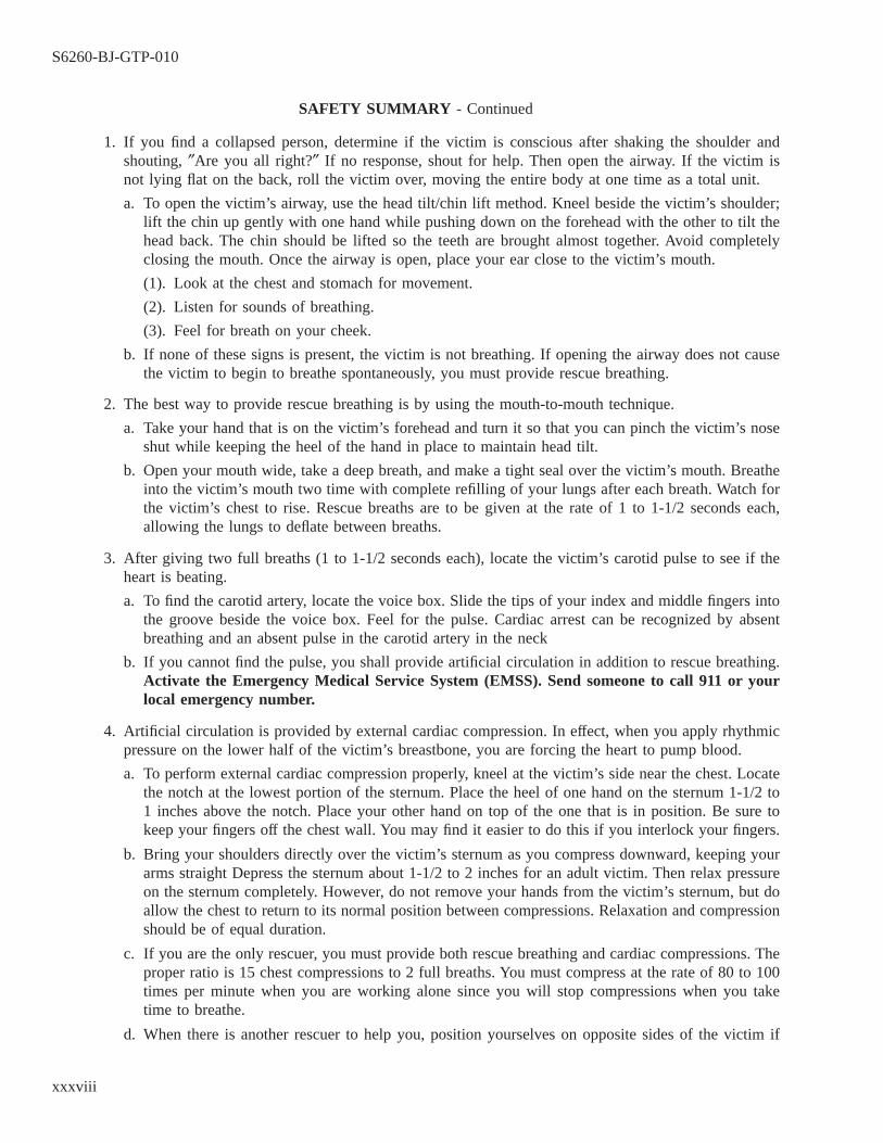
SAFETY SUMMARY - Continued
1. If you find a collapsed person, determine if the victim is conscious after shaking the shoulder andshouting, ″Are you all right?″ If no response, shout for help. Then open the airway. If the victim isnot lying flat on the back, roll the victim over, moving the entire body at one time as a total unit.
a. To open the victim’s airway, use the head tilt/chin lift method. Kneel beside the victim’s shoulder;lift the chin up gently with one hand while pushing down on the forehead with the other to tilt thehead back. The chin should be lifted so the teeth are brought almost together. Avoid completelyclosing the mouth. Once the airway is open, place your ear close to the victim’s mouth.
(1). Look at the chest and stomach for movement.
(2). Listen for sounds of breathing.
(3). Feel for breath on your cheek.
b. If none of these signs is present, the victim is not breathing. If opening the airway does not causethe victim to begin to breathe spontaneously, you must provide rescue breathing.
2. The best way to provide rescue breathing is by using the mouth-to-mouth technique.
a. Take your hand that is on the victim’s forehead and turn it so that you can pinch the victim’s noseshut while keeping the heel of the hand in place to maintain head tilt.
b. Open your mouth wide, take a deep breath, and make a tight seal over the victim’s mouth. Breatheinto the victim’s mouth two time with complete refilling of your lungs after each breath. Watch forthe victim’s chest to rise. Rescue breaths are to be given at the rate of 1 to 1-1/2 seconds each,allowing the lungs to deflate between breaths.
3. After giving two full breaths (1 to 1-1/2 seconds each), locate the victim’s carotid pulse to see if theheart is beating.
a. To find the carotid artery, locate the voice box. Slide the tips of your index and middle fingers intothe groove beside the voice box. Feel for the pulse. Cardiac arrest can be recognized by absentbreathing and an absent pulse in the carotid artery in the neck
b. If you cannot find the pulse, you shall provide artificial circulation in addition to rescue breathing.Activate the Emergency Medical Service System (EMSS). Send someone to call 911 or yourlocal emergency number.
4. Artificial circulation is provided by external cardiac compression. In effect, when you apply rhythmicpressure on the lower half of the victim’s breastbone, you are forcing the heart to pump blood.
a. To perform external cardiac compression properly, kneel at the victim’s side near the chest. Locatethe notch at the lowest portion of the sternum. Place the heel of one hand on the sternum 1-1/2 to1 inches above the notch. Place your other hand on top of the one that is in position. Be sure tokeep your fingers off the chest wall. You may find it easier to do this if you interlock your fingers.
b. Bring your shoulders directly over the victim’s sternum as you compress downward, keeping yourarms straight Depress the sternum about 1-1/2 to 2 inches for an adult victim. Then relax pressureon the sternum completely. However, do not remove your hands from the victim’s sternum, but doallow the chest to return to its normal position between compressions. Relaxation and compressionshould be of equal duration.
c. If you are the only rescuer, you must provide both rescue breathing and cardiac compressions. Theproper ratio is 15 chest compressions to 2 full breaths. You must compress at the rate of 80 to 100times per minute when you are working alone since you will stop compressions when you taketime to breathe.
d. When there is another rescuer to help you, position yourselves on opposite sides of the victim if
S6260-BJ-GTP-010
xxxviii

SAFETY SUMMARY - Continued
possible. One of you should be responsible for interposing a breath during the relaxation after eachfifth compression. The other rescuer, who compresses the chest, should use a rate of 60 compres-sions per minute.
RATE OF COMPRESSION.
Rescuers Ratio of Compressions to Breaths Rate of Compressions
ONE 15:2 80 times/min.TWO 5:1 60 times/min.
If you suspect the victim has suffered a neck injury, you must not open the airway in the usual manner. Ifthe victim is injured in a diving or vehicle accident, you should consider the possibility of such a neck injury. Inthese cases, the airway should be opened by using a modified jaw thrust, keeping the victim’s head in a fixed,neutral position. For additional information, refer to NAVSEA S9086-KC-STM-010/CH 300.
Specific warnings and cautions applying to the system/equipment covered by this manual are summarizedbelow. These warnings and cautions appear elsewhere in the manual following paragraph headings and immedi-ately preceding the text to which they apply. They are repeated here for emphasis
WARNING
Electric motors use high voltages capable of causing death. Use extremecaution when working near the power source and load components. Electricmotor controllers are not approved for component isolation. Ensure control-ler power isolation (circuit breaker, fuses) is tagged out. (Page 1-15)
WARNING
High voltages may be present at any of the red binding posts, depending onthe switch settings. Handle this instrument carefully. (Page 2-5)
WARNING
DANGER: This instrument provides a high test voltage and can be danger-ous to personnel. Particular care should be used in the measurement ofcapacitor leakage because LETHAL VOLTAGE may be stored in the capaci-tor being tested. Always set the function switch to discharge before connect-ing or disconnecting a component. (Page 2-6)
S6260-BJ-GTP-010
xxxix
WARNING
DANGER: This instrument provides a high test voltage and can be danger-ous to personnel. Particular care should be used in the measurement ofcapacitor leakage because LETHAL VOLTAGE may be stored in theunknown’s capacitor. Always set the function switch to DISCHARGE beforeconnecting or disconnecting the unknown component. (Page 2-11)
WARNING
Do not attach or touch leads to any circuit or unit where a voltage may bepresent. (Page 2-14)
WARNING
Do not come into contact with test leads during testing. Do not attempt pre-setting output for high-potential testing. (It is also not recommended forsurge testing.) Be sure that all switches and controls are in their properpositions for the testing mode desired. (Page 2-20)
WARNING
Wear rubber gloves to prevent hand contact with bare conductors. (Page2-30, page 2-31)
WARNING
DANGER: Never leave the Strobotac unattended while in operation. TheStrobotac makes a moving object appear to be stationary. A person could beseriously injured by touching a moving object which appears to be station-ary. (Page 2-36)
WARNING
DANGER: The output of this instrument can be lethal. It must be used onlyby qualified personnel. The operator must always be safety conscious. (Page2-42)
S6260-BJ-GTP-010
xl

WARNING
Never conduct a high-potential test on a winding that has failed a groundinsulation test. (Page 2-45, page 5-15)
WARNING
DANGER: The output of this instrument can be lethal. It must be used onlyby qualified personnel. (Page 2-47)
WARNING
Both ac and dc jacks are energized when the voltage range selector switch isset to HIGH. To ensure operator safety, an external interlock switch must beused at all times. Follow the procedure in paragraph 2-43 to modify theinstrument so that an interlock switch may be mounted. (Page 2-47)
WARNING
NEVER conduct a high-potential test on a winding that has failed a groundinsulation test. (Page 2-48)
WARNING
DANGER: The output of this instrument can be lethal. It must be used onlyby qualified personnel. The operator must always be safely conscious. (Page2-51)
WARNING
Both ac and dc jacks are energized when high voltage is activated. (Page 2-51)
WARNING
DANGER: Electric motors use high voltages capable of causing death. Useextreme caution when working near the power source and load components.
S6260-BJ-GTP-010
xli

Always use proper safety equipment to include such items as insulated mat-ting and protective gloves. Observe correct tag-out procedures. (Page 3-3)
WARNING
Take care when using metal tools around an electric motor with energizedlines. Handle tools properly to avoid dropping them. Mishandling can acci-dentally cause a short circuit which could harm personnel or damage equip-ment. (Page 3-3)
WARNING
High voltages capable of causing death are used in electric motors. Useextreme caution when working near the power source and load components.Always wear proper safety equipment. Observe correct tag-out procedures.(Page 3-6)
WARNING
Electric motors use high voltages capable of causing death. Use extremecaution when working near the power source and load components. Alwaysuse proper safety equipment to include such items as insulated matting andprotective gloves. Observe correct tag-out procedures.
Take care when using metal tools around an electric motor with energizedlines. Handle tools properly to avoid dropping them. Mishandling can acci-dentally cause a short circuit which could harm personnel or damage equip-ment. (Page 3-11)
WARNING
High voltages capable of causing death are used in electric motors. Useextreme caution when working near the power source and load components.Always wear safety equipment. Observe correct tag-out procedures. (Page4-2)
WARNING
To ensure that it is working properly, use only a voltmeter that has beenchecked out on a known live circuit. (Page 4-2)
S6260-BJ-GTP-010
xlii
WARNING
Avoid horizontal lifts which put a bending load on lifting eyes. Use extremecaution if such lifts must be made. They can be dangerous to personnel andequipment. (Page 4-10)
WARNING
DO NOT use a heavily corroded eyebolt. (Page 4-11)
WARNING
Before giving a hoisting signal, check to ensure that all members of the crewhave removed their hands from slings, hooks, and loads. See that all person-nel are clear of the lifting rig and tag lines, and that loose parts or objectsare properly secured.
Know the load capacity of the rig being used. Ensure that its capacity is notexceeded. (Page 4-12)
WARNING
Make sure that all deckplate openings have been roped off along the trans-portation route. (Page 4-13)
WARNING
Wear safety eyeglasses or goggles when grinding. (Page 6-32)
WARNING
DANGER: Wear lint-free insulated gloves or use clean cloths when handlinghot bearings. (Page 6-42)
S6260-BJ-GTP-010
xliii

WARNING
Improper or playful use of the high-pressure hose may cause severe injuryto internal organs and eardrums. Never allow compressed air to contact orenter any persons body. Always use proper safety equipment such as facemasks and goggles. (Page 7-2)
WARNING
Insulated gloves should be worn when steam cleaning to protect the opera-tor from being burned or scalded. (Page 7-4)
WARNING
Rust preventive compound may produce dizziness if adequate ventilation isnot provided. (Page 7-11)
WARNING
Solvents must be used with extreme care while following all applicable safetyprecautions for the type of solvent used. Most solvents are toxic and can beharmful to personnel if vapors are breathed or if the liquid comes into con-tact with the skin. Solvents should not be used where contact with openflame or extremely hot surfaces might occur because of the danger of fire orthe generation of toxic fumes. Proper personnel protective equipment mustbe worn and adequate ventilation provided whenever solvents are used.Refer to NAVSEA S9086-KC-STM-010/CH 300 for the names of approvedsolvents, methods of use, and safety precautions required. (Page 7-11)
WARNING
This solvent is highly flammable. Its use requires the strictest observance ofall safety precautions pertaining to open flames, smoking, or spark produc-ing activity. (Page 7-12)
WARNING
Wear insulated gloves when removing the hot stator from the oven. (Page8-9)
S6260-BJ-GTP-010
xliv

WARNING
Use a clear plastic face mask and insulated gloves since the items beinghandled are hot and will not quickly cool. (Page 8-16)
WARNING
Use insulated gloves and a plastic face shield when moving the stator. (Page8-16)
WARNING
Always use insulated gloves when placing the stator in the oven or removingit. (Page 8-18)
WARNING
Always use insulated gloves when dipping and baking. (Page 8-18)
WARNING
Always use insulated gloves when removing a stator from an oven. (Page8-19)
WARNING
Remove jewelry from hands, remove ties or tuck ties into shins, tuck inshirttails, roll down long sleeves, and button cuffs before operating the wind-ing machine. (Page 9-1)
WARNING
NOMEX insulation has a very sharp edge and can easily cut an operator’shands. (Page 9-15)
S6260-BJ-GTP-010
xlv

WARNING
Do not permit smoking, welding, or open flames near an open tank. Varnishhas a very low flashpoint. (Page 10-6)
WARNING
Do not weld, smoke, or allow open flames in the vicinity of an open varnishtank. Varnish thinners have very low flashpoints. (Page 10-11)
WARNING
Running some types of equipment in the wrong direction may injure person-nel or damage the motor. (Page 12-2, page 12-5)
WARNING
Test the voltmeter on a known live circuit before using it to ensure that it isworking properly. (Page 12-2)
WARNING
DANGER:
Closely follow the established ship procedure. High voltages used in opera-tion of electrical equipment can cause DEATH ON CONTACT if personnelignore safety precautions. Use extreme caution when working near thepower source and load components. (Page 12-4)
CAUTION
Do not slide the instrument along the cover gasket. Sliding will damage thegasket. (Page 2-5)
S6260-BJ-GTP-010
xlvi
CAUTION
A left deflection of the needle at this setting means that there is a ground orshort and no further measurement is possible. Secure the test at once. (Page2-7)
CAUTION
Do not slide the instrument along the gasket. This will tear the gasket. (Page2-10)
CAUTION
If the display does not stop flashing after the higher range switches aredepressed (see note below), it indicates an open circuit. (Page 2-15, page 2-16)
CAUTION
Do not operate the TEST LEAD SELECT switch while a test is in progress.(Page 2-21)
CAUTION
When testing very small windings, the tester can generate voltages in excessof the rating, which can damage the windings. Use caution to limit the per-cent of output to the nameplate rating. (Page 2-21)
CAUTION
Do not operate the tester with a vertical display that exceeds the size of theCRT grid. (Page 2-22)
CAUTION
This test should be stopped when a sharp rise in current is obtained. Do notattempt to preset high-potential voltage. Always begin testing at minimum.Upon completion of test, allow sufficient time for winding to discharge com-pletely. (Page 2-24)
S6260-BJ-GTP-010
xlvii

CAUTION
Do not allow the overcurrent relay to trip. Tripping the relay produces aninductive voltage surge which could damage the insulation. Increase the testvoltage slowly enough to see an abrupt rise in the slope of the leakage cur-rent curve and to stop the test. (Page 2-24)
CAUTION
Use only a 115 Vac power supply. Growlers must have the rotor in placebefore energizing. Energizing a growler without a rotor in place could dam-age the growler. (Page 2-27)
CAUTION
Do not rotate the rotor in the V block. Deenergize the growler before liftingthe rotor from the growler. Failure to do so will cause damage to thegrowler. (Page 2-27)
CAUTION
Remove the OHMPROBE fuse and battery attachment from the instrumentbefore measuring volts. The fuse will burn out if it is not removed. (Page2-30)
CAUTION
Remove the OHMPROBE fuse and battery attachment from the instrumentbefore measuring amperes. The fuse will burn out if it is not removed. (Page2-31)
CAUTION
Do NOT connect test leads. (Page 2-32)
CAUTION
Ensure all power is secured and all capacitors are discharged before testingfor resistance or continuity. (Page 2-36)
S6260-BJ-GTP-010
xlviii

CAUTION
Ensure that the power matches the data on the plate next to the power cordon the panel before plugging the power cord into the receptacle. (Page 2-38)
CAUTION
Model 710-1 contains oil-filled transformers. Install the unit on a sturdy,level platform, and strap it down to prevent sliding or tilting. Tilting willcause loss of transformer oil. (Page 2-43)
CAUTION
Ensure that the instrument ground is firmly connected to the ships hull.Connect the ground lead to the instrument and motor. (Page 2-46)
CAUTION
Twist together the leads of the winding not being tested when testing a two-speed, two-layer winding. Ground the winding not under test. (Page 2-46)
CAUTION
Take care not to damage the dial indicator. Installed motors may not haveclearance for full 360-degree rotation. (Page 2-55)
CAUTION
Handle standards with extreme care. Keep them on a clean, soft surface.(Page 2-61)
CAUTION
Use a rocking motion with the snap gage to avoid damaging the anvils. (Page2-63)
S6260-BJ-GTP-010
xlix

CAUTION
Take care when using any conducting tool around an electric motor withenergized lines. Handle tools properly to avoid dropping them. Mishandlingcan accidentally cause a short circuit that could damage equipment. (Page3-6)
CAUTION
Make sure that equipment serviced by the motor may be safely operatedbefore conducting an operational test. (Page 3-10)
CAUTION
Take care when using any conducting tool around an electric motor withenergized lines. Handle tools properly to avoid dropping them. Mishandlingcan accidently cause a short circuit that could damage equipment or injurepersonnel. (Page 4-2)
CAUTION
Handle low-noise electric motors carefully. Handling damage can cause highvibration levels and reduce mechanical or electrical reliability. (Page 4-4)
CAUTION
Hooks may straighten out and drop their load when overloaded. A hookshould NEVER be rebent and put back in service if it has been stretched orspread by overloading. It should be destroyed by cutting it in half with acutting torch. (Page 4-7)
CAUTION
The lower hook is usually the weakest part of a chain hoist. Spreading in thehook is a signal to the operator that the chain hoist is nearing the overload-ing point. Therefore, close observation by the operator is necessary to detectany sign of overloading in time to prevent damage to the hoist. Ordinarily,pull exerted by one or two people on a chain hoist is not enough to overloadit. (Page 4-8)
S6260-BJ-GTP-010
l

CAUTION
Have the equipment operator conduct a thorough inspection of all safetydevices before starting a job. Hoist controls, brakes, and clutches must beinspected. (Page 4-10)
CAUTION
Do not use a hammer to remove the coupling. (Page 4-13)
CAUTION
Never be hasty or careless in disassembling a generator or a motor. Handlethe components with care to avoid damaging them, or causing a need foradditional adjustment.
Always use extreme care in selecting tools and labeling and storing partswhen disassembling a motor. (Page 5-6)
CAUTION
Do not file or stone mating surfaces without expert supervision. Excessivefiling can damage the flange. (Page 5-6)
CAUTION
Do not allow the rotor to drop down on the lamination when the motor isbeing disassembled. Use jacks and a pipe to support the rotor while the endbells are being removed. (Page 5-6)
CAUTION
Be careful not to let the rotor rub against the lamination or the end of thewindings. Do not allow the pipe to damage bearing areas. (Page 5-9)
CAUTION
Never use a naked flame to heat a shaft, bearing, or housing. This can sig-nificantly distort the components. (Page 6-28, page 6-38)
S6260-BJ-GTP-010
li
CAUTION
Never use a torch to loosen a bearing. A torch may cause shaft distortion.(Page 6-29, page 6-32)
CAUTION
Use the chisel to split the bearing race only. Do not try to cut the race witha chisel. (Page 6-33)
CAUTION
Be certain that the tube or nozzle, if used, has no sharp edges which mightscrape insulation. (Page 7-1)
CAUTION
Take care when removing the material. Chips or other rough matter adher-ing to the cloth may scratch or remove insulation.
Foreign matter may be pushed or pressed into an inaccessible opening if thematerial to be removed is close to such an opening. This will create moreserious problems. (Page 7-2)
CAUTION
Ensure that any accumulation of moisture in the air lines has been removed.Remove any moisture by operating the air away from the stator to becleaned long enough to blow moisture out of the line.
Ensure that foreign material is actually being removed by blowing it fromthe stator. Ensure that material is not deposited deeper into inaccessiblecrevices.
Air pressure must not exceed 30 pounds per square inch.
Ensure the removal of dirt-laden air whenever compressed air is used toremove foreign material. Ensure that there is suction on the opening at theend opposite the air jet.
Use compressed air with caution. Abrasive particles may puncture insulationand be forced under insulating tape. (Page 7-2)
S6260-BJ-GTP-010
lii
CAUTION
Take care to keep live steam from impinging directly on the windings. Thetemperature of the solutions at the windings should not exceed 194° F (90°C). The pressure should not exceed 30 psi. (Page 7-4)
CAUTION
Always consult and follow the manufacturer’s instructions before operatingvacuum drying machinery. (Page 7-6)
CAUTION
This product may have a corrosive effect on paint, varnish, and insulation.Keep it clear of windings and fabric insulation. (Page 7-11)
CAUTION
Dry cleaning solvent type II, P-D-680 (NSN 6850-00-274-5421), may be dam-aging to some types of insulation. A test should be made to a small spotbefore using. (Page 7-12)
CAUTION
Do not crack the varnish, as leads may be broken. It will then be impossibleto determine connections when pulling the leads up.
Cut off the end turns of encapsulated motors to prevent uncontrolled firesin the oven. Some motors have alloy parts which may distort at 600-700° F(316-371° C). High temperatures may adversely affect iron characteristics.To avoid damage to the lamination/insulation motors, burnout should beconducted below 700° F (371° C). (Page 8-9)
CAUTION
Keep the saw clear of stator laminations. (Page 8-13)
CAUTION
Do not allow the heater cables to catch on obstructions while rotating theturntable. The heater leads may be pulled and shorted if leads are allowedto catch. (Page 8-16)
S6260-BJ-GTP-010
liii

CAUTION
Be careful when sandblasting to ensure that the stator laminations are notloosened. (Page 8-17)
CAUTION
Do not use compressed air to clean slots. It may contaminate the stator withmoisture. (Page 8-17)
CAUTION
Do not use silicone glass laminate or varnished glass-fiber cloth in a totallyenclosed motor-generator set if one machine is direct current with carbonbrushes. This arrangement causes excessive carbon brush wear. (Page 9-13)
CAUTION
Do not allow the scissors to cut or abrade the magnet wire insulation. (Page9-19)
CAUTION
Be careful not to damage the slot cell material, wedges, or magnet wireinsulation when bending the coils. (Page 9-20)
CAUTION
The winding must not touch the end bell at any point or the motor will burnout. (Page 9-26)
CAUTION
Compatibility tests must be conducted between varnish held in the dip tankfor over a month and varnish from closed containers. Do this even thoughmanufacturer and batch numbers are the same. (Page 10-2)
S6260-BJ-GTP-010
liv
CAUTION
Certain varnishes not qualified under MIL-I-24092 are likely to be incom-patible with varnish qualified under MIL-I-24092. (Page 10-5)
CAUTION
Do not thin solventless varnish. (Page 10-11)
CAUTION
Varnish should never be applied to the whole or any part of a winding,either by dipping, spraying, or brushing, until the winding has been thor-oughly cleaned and dried. Varnishing a dirty or moist winding seals in dirtor moisture and makes future cleaning impossible. (Page 10-12)
CAUTION
Read the operating instructions carefully before starting a motor. Failure tounderstand the instructions may result in unnecessary delay in recognizingabnormal operation. It may also lead to permanent damage to the equip-ment. (Page 12-5)
S6260-BJ-GTP-010
lv / (lvi Blank)

lvi@@FIpgtype@@BLANK@@!FIpgtype@@
CHAPTER 1
INTRODUCTION SECTION
SECTION
1-1. SCOPE.
This chapter contains three sections. Section I and Section II are brief introductions to quality assurance (QA)and tag-out procedures as they apply to the Intermediate Maintenance Activity (IMA) or Fleet MaintenanceActivity (FMA). Section III includes information specifically related to electric motor repair. Topics include:
1-1.1 Introduction to QA (paragraph 1-2).
1-1.2 Definition of terms (paragraph 1-4).
1-1.3 Work packages (paragraph 1-6).
1-1.4 Levels of assurance (paragraph 1-12).
1-1.5 Material requirements (paragraph 1-14).
1-1.6 Departures from specifications (paragraph 1-16).
1-1.7 Responsibilities of shop Quality Control Inspector (QCI) (paragraph 1-18).
1-1.8 Responsibilities of repair personnel (paragraph 1-20).
1-1.9 Introduction to tag-out (paragraph 1-22).
1-1.10 Tag-out responsibilities (paragraph 1-24).
1-1.11 Tags and records (paragraph 1-26).
1-1.12 Tagout of electric motors (paragraph 1-28).
1-1.13 Introduction to electric motors (paragraph 1-30).
1-1.14 Functions of the electrical repair shop (paragraph 1-35).
SECTION I
QUALITY ASSURANCE
1-2. INTRODUCTION TO QA.
1-3.
The QA Program has been developed to provide a system to ensure that repair procedures and materials meetestablished maintenance standards and specifications. QA has received increased emphasis because of the con-stantly rising cost of material and manpower. QA is an all-hands responsibility, and repair personnel as well asmaintenance managers must meet established requirements. To reinforce the QA Program, each IMA/FMA has aQA office. Detailed QA guidance is provided by CINCLANTFLT/CINCPACFLTINST 4790.3, Joint Fleet Main-tenance Manual (JFMM).
S6260-BJ-GTP-010
1-1

1-4. DEFINITION OF TERMS.
1-5.
Several terms are frequently used when describing QA requirements. The definitions of some commonly usedterms include:
1-5.1 Quality Control (QC). QC consists of all actions taken prior to the start of and during the work processto: (1) obtain the highest confidence level that the work will be completed safely and correctly within technicalspecifications the first time and (2) minimize expenditure of manpower and material resources.
1-5.2 Quality Assurance (QA). QA consists of administrative and technical procedures to ensure compliancewith technical specifications, through a systematic review of QC records and production actions. These proce-dures provide proof and confidence that work performed or material manufactured will perform as designed andthat there is documentary evidence to that effect.
1-5.3 Objective Quality. Any statement of fact, either quantitative or qualitative, pertaining to the ObjectiveQuality of Evidence (OQE) or a product or service based on observations, measurements, or tests which can beverified. (Evidence will be expressed in terms of specific quality requirements or characteristics. These charac-teristics are identified in drawings, specifications, and other documents which describe the item, process, or pro-cedure.)
1-5.4 Controlled Material. Controlled material is any material which must be identified throughout the manu-facturing and repair process in order to meet the specifications required of the end product. Any material whichthe Repair Officer (RO), Engineering Officer, Planning and Estimating (P&E) Officer, QA Officer, or a divisionofficer determines must be identified throughout the repair process may be considered controlled material. Con-trolled material is further identified by material markings, as well as applicable QA forms, and is placed in seg-regated storage. The QA form used to identify controlled material is the Material In-Process Control Tag (QAForm 2) (figure 1-1).
1-5.5 Formal Work Procedures (FWP). FWPs are documents which provide the technician with clear, concise,and technically correct instructions for performing the assigned maintenance task. FWPs will vary in complex-ity with the type of work being performed, adequacy of existing procedures, and extent of preparation and recov-ery required. The intent is to provide technicians with a plan with which they can reasonably be expected tocomplete the job correctly. FWPs should be only as detailed as required by the complexity of the work, techni-cian knowledge, Quality Control (QC) requirements, Quality Assurance (QA) requirements, extent of tests, andlevel of worker supervision required.
1-5.6 Material Identification and Control (MIC) Number. The MIC is a unique number which is assigned to(and required on) all parts that form the pressure boundary of a completed assembly. This number is used to tracematerial to certification records, and is used in addition to other markings required by the specifications of amanufacturer’s contract.
1-5.7 Certified Level I Material. The Level I category includes material that has been specifically identified bya quality certification activity. Items in this category are assigned MIC numbers and are accompanied by certifi-cation documents.
S6260-BJ-GTP-010
1-2

1-6. WORK PACKAGES.
1-7.
The QA Program requires that repair procedures and materials used be properly identified. The means ofdocumenting this information for IMA use is the work package. The work package contains the various mainte-nance forms and associated documents (drawings, instructions, FWPs, etc.) required to perform a particularmaintenance action.
1-8. CRITICAL QUALITY CONTROL POINTS.
Work process, regardless of type (maintenance, training, administrative, etc.), have critical execution pointswhose proper accomplishment overwhelmingly affects the ultimate first-time quality success of the process.Quality Maintenance Program work processes identify these crucial work process points as Critical Quality Con-trol Points (Q-Points). The concepts below apply to Q-Points:
1-8.1 Q-Points in a work process are typically characterized by requiring high-level skills, proficiency, strongknowledge, working within narrow tolerances, and/or difficult environmental conditions which mandate closesupervision.
Figure 1-1 Material In-Process Control Tag (QA Form 2)
S6260-BJ-GTP-010
1-3
1-8.2 Q-Points are determined by the organizational unit (work center, division, command, etc.) with cognizanceover the specific work process.
1-8.3 Maintenance managers shall give strong focus to Q-Points in working scheduling, personnel assignments,and appropriate supervision.
1-9. SHIPS MAINTENANCE ACTION FORM (OPNAV Form 4790/2K).
The OPNAV Form 4790/2K, known as the 2-Kilo , is used to provide basic information for a work package.The tended unit is responsible for preparing the 2-Kilo for submission to the IMA. If the 2-Kilo is improperlyprepared or incomplete, the Type Commander’s Representative (TYCOM Rep) or the IMA will return it to thetended unit for correction. Today, most ships use the 4790/2K only onboard. The planning data are delivered bycomputer to the repair activity as an automated work request (AWR).
1-10. MAINTENANCE PLANNING AND ESTIMATING FORM (OPNAV Form 4790/2P).
OPNAV Form 4790/2P (figure 1-2) is used to provide planning data to the work package. The form is com-pleted by the IMA Planning and Estimating (P&E) Office and accompanies an OPNAV Form 4790/2K (AWR)which has been submitted by a tended unit.
1-11. CONTROLLED WORK PACKAGES (CWPs).
A CWP (figure 1-3) provides the records (i.e., QA forms such as QA Form 17 [figure 1-4] or QA Form 49Series [figure 1-5]) to document approval of maintenance, conduct of repair, and recertification of component(s)and system(s) subsequent to repair.
1-11.1 The CWP includes the FWP which provides the step-by-step instructions a technician can follow to prop-erly accomplish work. FWPs vary widely in scope and complexity. A Maintenance Requirement Card (MRC)may serve as an adequate FWP in the case of quarterly PMS inspections. In most cases of complex correctivemaintenance, an FWP must be developed for a specific task, such as replacement of a valve welded into a nuclearsystem. Frequently, Fleet Maintenance Activities (FMAs) and Ship’s Force are able to reuse FWPs developed forpreviously accomplished work. FWPs are also required for some types of non-QA work.
1-11.2 A CWP is an FWP to which appropriate QA forms have been attached. When authorized by higherauthority (i.e., Immediate Superior in Command [ISIC]), the QA Form 9 is used and becomes the cover sheet ofthe work package. The QA forms are generally used to meet Naval Sea Systems Command (NAVSEA)/NavalAir Systems Command (NAVAIR) requirements for documenting OQE of replacement parts, proper assembly ofcomponents, or satisfactory testing of systems. An FWP used for QA work becomes part of a CWP and includessteps which list inspections that must be performed by specially trained personnel and QA forms to be completedduring accomplishment. The intent of requiring a CWP is to ensure that the proper records are completed duringmaintenance and retained as required by the applicable standard to support continued certification of the ship.QA Form 17 is used to provide a test or inspection requirement for which there is no other existing document.
1-12. LEVELS OF ASSURANCE.
1-13.
The increased cost of shipboard systems and equipment has generated a need for stricter controls over main-tenance actions. These controls include guidelines which repair personnel must follow when performing mainte-nance on certain systems or equipment. Some of these controls include maintenance requirements which are
S6260-BJ-GTP-010
1-4
called levels of assurance. The following paragraphs summarize the levels of assurance. For a full description oflevels of assurance, refer to CNCLANTFLT/CINCPACFLTINST 4790.3.
1-13.1 Level A. Level A requires that maximum confidence be placed in the reliability of repairs made to spe-cific systems and equipment.
1-13.2 Level B. Level B allows less confidence to be placed on the reliability of repairs made to specific sys-tems and equipment than on Level A repairs.
1-13.3 Level C. Repairs under the category Level C are assumed to be correct unless there are obvious indi-cations to the contrary.
S6260-BJ-GTP-010
1-5

Figure 1-2 Maintenance Planning and Estimating Form (OPNAV Form 4790/2P)
S6260-BJ-GTP-010
1-6
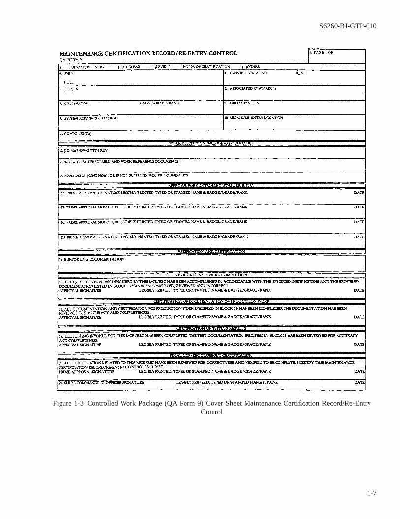
Figure 1-3 Controlled Work Package (QA Form 9) Cover Sheet Maintenance Certification Record/Re-EntryControl
S6260-BJ-GTP-010
1-7
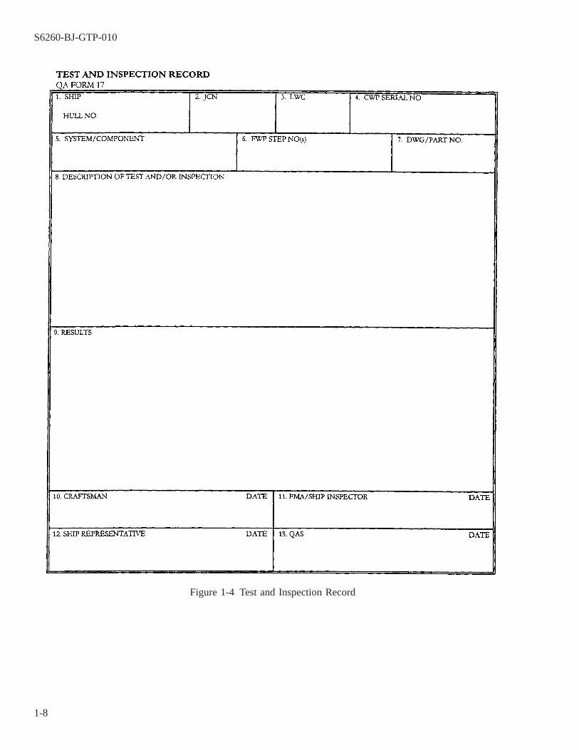
Figure 1-4 Test and Inspection Record
S6260-BJ-GTP-010
1-8
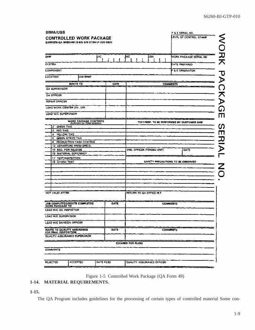
1-14. MATERIAL REQUIREMENTS.
1-15.
The QA Program includes guidelines for the processing of certain types of controlled material Some con-
Figure 1-5 Controlled Work Package (QA Form 49)
S6260-BJ-GTP-010
1-9
trolled materials are categorized as Level I. Level I is the designation given to systems which require maximumconfidence that the composition of installed material is correct. The use of Level I material is restricted and care-fully controlled.
1-16. DEPARTURES FROM SPECIFICATIONS.
NOTE
All references for Departures from Specifications (DFS) are in CINCLANT-FLT/CINCPACFLTINST 4790.3, Chapter 7.
1-17.
The IMA has a basic obligation to perform all repairs in full accordance with specifications. However, thereare occasions during the repair process when repairs cannot, or are not, performed according to specifications.The occasions when repairs are not performed according to specifications are referred to as Departures FromSpecifications (DFS) (QA Form 12) (figure 1-6).
1-17.1 A DFS (non-nuclear only) is a lack of compliance with any authoritative document, plan, procedure,instruction etc.
1-17.1.1 During a maintenance action, a DFS is required for lack of compliance with cognizant documents,drawings, etc. For “as found” conditions during maintenance, the Immediate Supervisor in Command (ISIC) (forSubmarines only), ship, and Fleet Maintenance Activity (FMA) (if involved) must evaluate the deviation usingthe guidance of CINCLANTFLT/CINCPACFLTINST 4790.3, paragraph 7.2.4.
1-17.1.2 For ″as found″ conditions or equipment failures during operations that result in noncompliance withcognizant documents, drawings, etc., the ship and/or ISIC (if inport) must evaluate the condition or failure usingthe guidance of CINCLANTFLT/CINCPACFLTINST 4790.3, paragraph 7.2.4 to determine if the deficiencymeets the criteria as a major DFS. If not, no DFS is required and the non-conforming condition will be enteredin the ship’s Current Ship’s Maintenance Project (CSMP). If at sea, the guidance of CINCLANTFLT/CINCPAC-FLTINST 4790.3, paragraph 7.3.8 will be followed.
1-17.2 Reporting Departures from Specifications. It is incumbent upon ships, FMA and ISICs to discuss poten-tial DFS as early as possible (prior to the work close out or component assembly if possible) to determine direc-tion of actions, and alternatives to the DFS. Every effort must be made to correct each deficiency prior to equip-ment/system operation or underway of the ship. If a DFS has to be submitted, the request for it must be processedas soon as possible to enable an engineering evaluation of the DFS request and approval/disapproval to be grantedwithout disrupting ship’s operations.
1-17.3 Types of Departures from Specification. A DFS is used for non-nuclear items only. DFSs are classifiedas either MAJOR or MINOR depending on their significance. Major DFS require TYCOM or NAVSEA approvalwhile minor DFS are approved in accordance with CINCLANTFLT/CINCPACFLTINST 4790.3, paragraph 7.26.Major DFS which are considered temporary repairs are approved by the TYCOM. NAVSEA approval of majorDFS is required, if the condition is considered a permanent repair or NAVSEA technical guidance does not existfor the condition identified in the DFS. Care must be exercised in evaluating and determining the type of DFS.DFS must be approved prior to ship’s underway.
S6260-BJ-GTP-010
1-10

1-17.4 Permanent and Temporary Approval of Departure from Specification. DFS are approved as either per-manent or temporary depending upon the nature of noncompliance and technical determination of whether thedepartable condition needs to be repaired.
1-17.4.1 DFS which are approved as temporary DFS require subsequent action to correct the noncompliance andare approved with specific direction regarding duration and actions necessary to clear. Depending on the degreeof noncompliance, temporary DFS will be approved by the TYCOM or ISIC.
1-17.4.2 DFS which are approved as permanent DFS require no additional repair effort and will be approved byNAVSEA except for those for which specific and definite guidance allows TYCOM approval.
1-18. RESPONSIBILITIES OF SHOP QUALITY CONTROL INSPECTOR (QCI).
1-19.
QCIs are selected from repair personnel in the various repair shops, and are certified to perform certaininspections under the QA Program. The duties and responsibilities of QCIs include the following:
1-19.1 Coordinating and administering the QA Program within their respective work centers,
1-19.2 Being familiar with the requirements of the QA Program,
1-19.3 Ensuring that repairs performed by work center personnel meet QA requirements,
1-19.4 Maintaining records and files within the work center which support the QA Program,
1-19.5 Ensuring that shop personnel use only calibrated equipment or measuring devices which have currentcalibration stickers attached or available,
1-19.6 Performing required QC inspections of material repaired within the work center.
S6260-BJ-GTP-010
1-11
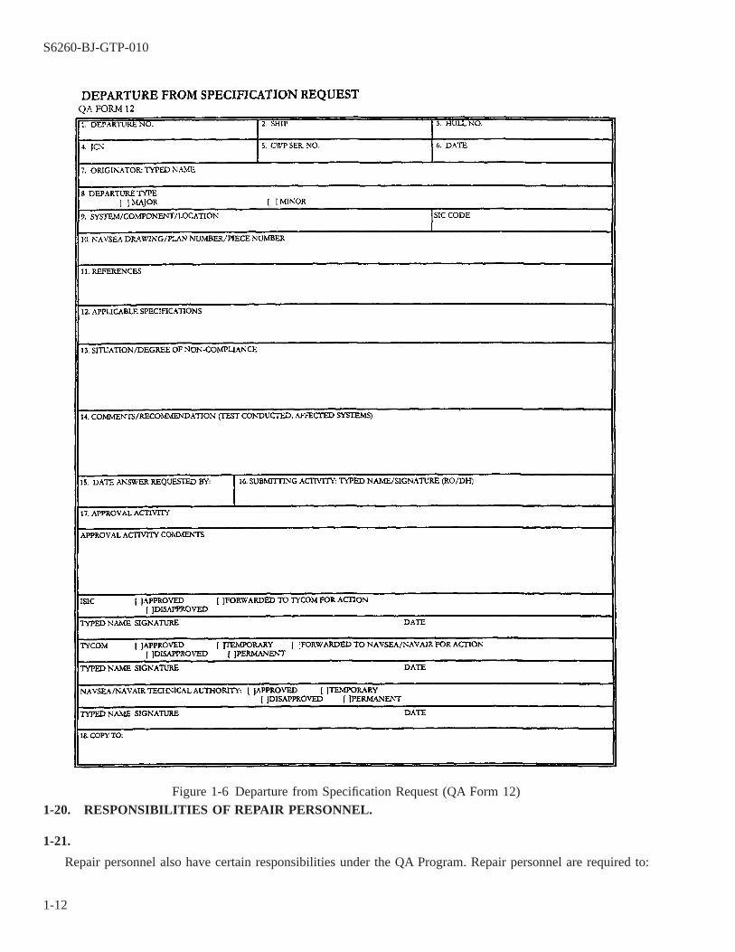
1-20. RESPONSIBILITIES OF REPAIR PERSONNEL.
1-21.
Repair personnel also have certain responsibilities under the QA Program. Repair personnel are required to:
Figure 1-6 Departure from Specification Request (QA Form 12)
S6260-BJ-GTP-010
1-12
1-21.1 Check work packages to ensure that they are complete; incomplete packages should be reported to theshop supervisor.
1-21.2 Follow instructions contained in FWPs or CWPs.
1-21.3 Perform repairs in accordance with established specifications.
1-21.4 Use precision measuring instruments and inspection tools and gages when required.
1-21.5 Ensure that all test and measuring equipment used is properly calibrated.
1-21.6 Report any situations which may require a departure from specifications.
SECTION II
INTRODUCTION TO TAG-OUT
1-22. INTRODUCTION TO TAG-OUT.
1-23.
Proper tag-out procedures are necessary to ensure the safety of personnel and equipment. A repair activitymay work on electric motors or generators for which the ship’s force has responsibility. In that situation, autho-rized representatives of both the repair activity and the ship’s force must sign the tags. This ensures:
1-23.1 Maximum safety of repair personnel,
1-23.2 Safe operation of the ship,
1-23.3 Safe operation of associated equipment, and
1-23.4 Safe conditions for the ship’s personnel.
1-24. TAG-OUT RESPONSIBILITIES.
1-24.1 The tended unit’s commanding officer is responsible for tag-out procedures in his command. The Officerof the Deck (OOD), the Engineering Officer of the Watch (EOOW), and the Damage Control Assistant (DCA)also have responsibilities, as discussed in this and subsequent paragraphs.
1-24.2 When repairs are performed by a repair activity, a dual responsibility exists:
1-24.2.1 The tended unit is responsible for, and controls, the tag-out procedures and the equipment beingrepaired.
S6260-BJ-GTP-010
1-13

1-24.2.2 The IMA is responsible for ensuring compliance with tag-out procedures and for concurring with thetag-out.
1-25. TAG-OUT PLANNING.
Careful planning of tag-outs reduces the number of record sheets and tags, and the nine required to performaudits, particularly during periods of overhaul or repair. Much of the tag-out planning is done during preavail-ability visits to the tended unit by Planning and Estimating (P&E) personnel. Tag-out planning must include areview of plans and systems to ensure complete tag-out boundaries.
1-26. TAGS AND RECORDS.
1-27.
The specific tags and record sheets involved in the tag-out procedure are as follows:
1-27.1 CAUTION Tag. A yellow CAUTION tag (figure 1-7) limits operation of equipment until specifiedinstructions are followed to ensure the safety of personnel, equipment, systems, or components.
1-27.2 DANGER Tag. A red DANGER tag (figure 1-8) prohibits operation of equipment that could jeopardizesafety of personnel or endanger equipment, systems, or components. It is prepared by the ship’s force petty officerin charge of the work.
1-27.3 DANGER/CAUTION Tag-out Record Sheet. The tag-out record sheet (figure 1-9) is used to recordeffective and cleared component and system tag-outs. It is prepared by the ship’s force petty officer in charge ofwork.
1-27.4 Tag-out Log. The tag-out log is the control document for administering the entire tag-out procedure.Tag-out logs are composed of effective and cleared DANGER/CAUTION tag-out index and record of audit sheetsand DANGER/CAUTION tag-out record sheets (figure 1-9). Tag-out logs are maintained for all ship’s systemsand equipment. The logs will ordinarily be maintained in the Damage Control Center (DCC). A copy of the ship’stag-out instructions should be included in the log. This ensures access to the instruction by all personnel.
1-27.5 Preparation of Tags and Record Sheets. For detailed instructions on preparation of tags and tag-outrecord sheets, refer to OPNAVINST 3120.32 and local tag-out instructions.
S6260-BJ-GTP-010
1-14
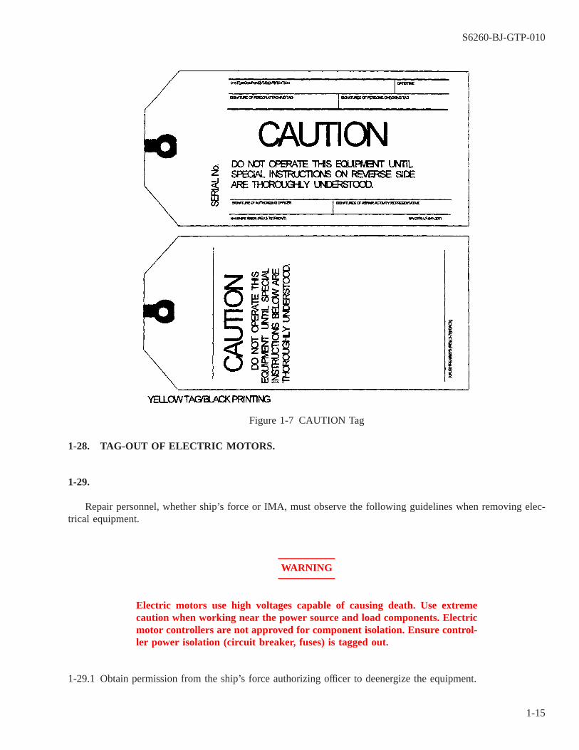
1-28. TAG-OUT OF ELECTRIC MOTORS.
1-29.
Repair personnel, whether ship’s force or IMA, must observe the following guidelines when removing elec-trical equipment.
WARNING
Electric motors use high voltages capable of causing death. Use extremecaution when working near the power source and load components. Electricmotor controllers are not approved for component isolation. Ensure control-ler power isolation (circuit breaker, fuses) is tagged out.
1-29.1 Obtain permission from the ship’s force authorizing officer to deenergize the equipment.
Figure 1-7 CAUTION Tag
S6260-BJ-GTP-010
1-15
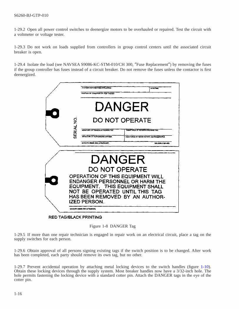
1-29.2 Open all power control switches to deenergize motors to be overhauled or repaired. Test the circuit witha voltmeter or voltage tester.
1-29.3 Do not work on loads supplied from controllers in group control centers until the associated circuitbreaker is open.
1-29.4 Isolate the load (see NAVSEA S9086-KC-STM-010/CH 300, ″Fuse Replacement″) by removing the fusesif the group controller has fuses instead of a circuit breaker. Do not remove the fuses unless the contactor is firstdeenergized.
1-29.5 If more than one repair technician is engaged in repair work on an electrical circuit, place a tag on thesupply switches for each person.
1-29.6 Obtain approval of all persons signing existing tags if the switch position is to be changed. After workhas been completed, each party should remove its own tag, but no other.
1-29.7 Prevent accidental operation by attaching metal locking devices to the switch handles (figure 1-10).Obtain these locking devices through the supply system. Most breaker handles now have a 3/32-inch hole. Thehole permits fastening the locking device with a standard cotter pin. Attach the DANGER tags in the eye of thecotter pin.
Figure 1-8 DANGER Tag
S6260-BJ-GTP-010
1-16
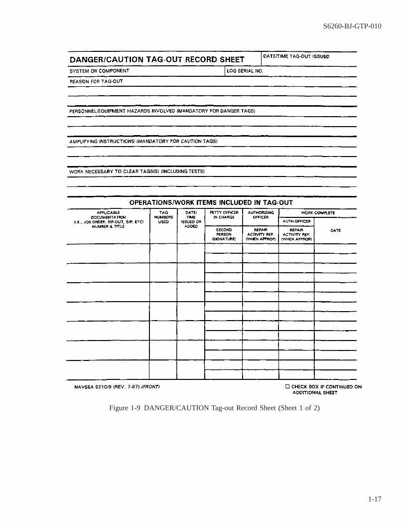
Figure 1-9 DANGER/CAUTION Tag-out Record Sheet (Sheet 1 of 2)
S6260-BJ-GTP-010
1-17
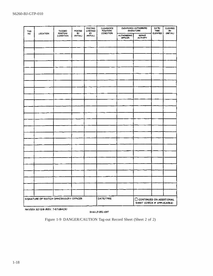
Figure 1-9 DANGER/CAUTION Tag-out Record Sheet (Sheet 2 of 2)
S6260-BJ-GTP-010
1-18
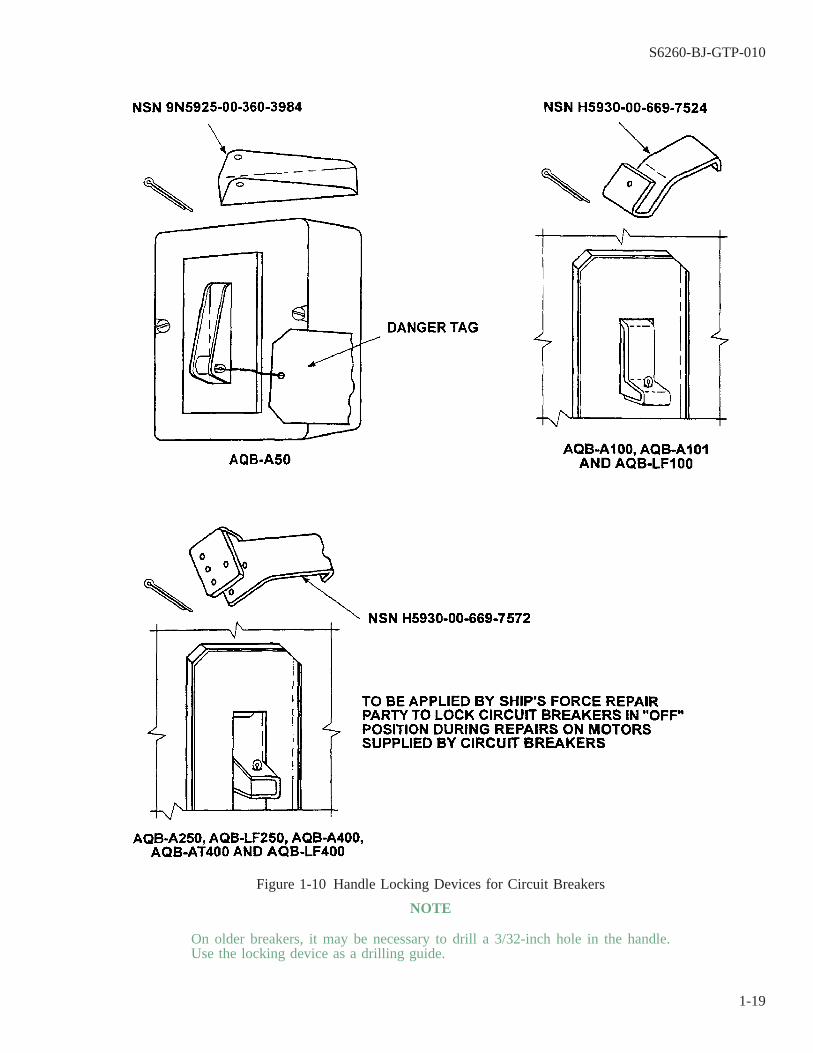
NOTE
On older breakers, it may be necessary to drill a 3/32-inch hole in the handle.Use the locking device as a drilling guide.
Figure 1-10 Handle Locking Devices for Circuit Breakers
S6260-BJ-GTP-010
1-19
1-29.8 Check metering and control circuits as well as power circuits. They must be deenergized. In many cases,metering and control circuits are connected to the supply side of the circuit breaker. When the circuit breaker isopened, a check of power circuits on the load side may show that they are dead. Metering and control circuitsmust be checked separately.
1-29.9 Check all points and identify all circuits supplying a unit. Many shipboard units have several sources ofpower. Each source of power must have its own tag.
1-29.10 Authorized representatives of both the repair activity and the ship’s force must sign the DANGER tags(figure 1-8) and the DANGER/CAUTION tag-out record sheet (figure 1-9). Tag-out procedures have rigidrequirements. When repairs or overhauls are performed by a repair activity, it is responsible for the safety of bothrepair and ship’s force personnel. The tended ship is responsible for and will control the tag-out system. Therepair activity is responsible for compliance with the tag-out procedure.
SECTION III
ELECTRIC MOTOR REPAIR
1-30. INTRODUCTION TO ELECTRIC MOTORS.
1-31.
Electric motors are provided for two types of service on combatant ships. Motors for driven auxiliaries thatare essential for the military effectiveness of the ship are furnished as Navy Service A. These motors are heavyduty and highly resistant to shock impact. Motors for auxiliaries that are not essential for the military effective-ness of the ship are furnished as Navy Service C. These motors are commercial marine type. On noncombatantships, motors are normally of the commercial marine type.
1-32. MOTOR RATINGS.
Motors are rated for continuous, intermittent, varying, or short time duty as required by the driven auxilia-ries. On intermittently operating motors, the nameplate will indicate the length of time the motor can be operatedwithout overheating.
1-33. VOLTAGE AND FREQUENCY VARIATIONS.
Motors installed in ships are designed to operate at ± 10 percent variation in the voltage indicated on thenameplate. Alternating current motors are also designed to operate at ± 5 percent variation in frequency indicatedon the nameplate. Loss in performance or decrease of life may be experienced if the motor operates on inputpower outside of these limits.
1-34. DESCRIPTION OF AC MOTORS.
Almost all ac motors used on Navy ships that are above the fractional horsepower size are polyphase induc-tion motors.
1-34.1 Polyphase induction motors have a primary winding (the stator winding) that is connected to a powersupply and a secondary winding (the rotor winding) which has no electrical connection to the power supply. Cur-rents in the primary winding set up a rotating magnetic field. The rotating magnetic field induces voltages andcurrents in the secondary winding, and gives rise to a mechanical force which turns the rotor.
S6260-BJ-GTP-010
1-20

1-34.2 A few squirrel cage synchronous and wound rotor motors are used in addition to polyphase inductionmotors. A squirrel cage synchronous motor is an induction motor in which the secondary winding is a perma-nently short-circuited winding, usually uninsulated, around the periphery of the rotor and joined by continuousend rings. A wound rotor motor consists of wound coils insulated from each other and laid in slots in the rotorcore. These coils are wye-connected and terminate at three slip rings.
1-34.3 Most motors are single speed. However, for some applications, multiple- or variable-speed motors areused.
1-34.4 Figure 1-11 shows across section and schematic of a typical polyphase induction motor. This example isa three-phase induction motor.
1-35. FUNCTIONS OF THE ELECTRICAL REPAIR SHOP.
1-36.
The Electrical Repair Shop (51A) is required to have the following capabilities with respect to the repair ofelectrical motors:
NOTE
The list below applies only to electric motors and is not a complete statement ofthe required capabilities of the Electrical Repair Shop. See NAVSEA S9810-AA-GTP-010/IMA for a complete list.
1-36.1 Inspect, test, and repair onboard ships’ electrical equipment, such as motors, generators, and motor gen-erators.
1-36.2 Wash, dry, clean, and degrease electrical machinery and components.
1-36.3 Burn out varnish insulation or epoxy encapsulation.
1-36.4 Disassemble, strip, rewind, varnish, dip, bake, reassemble, and test electrical rotating machines, includinggenerators, motors, and motor generator sets.
1-36.5 Wind replacement coils (except square wire) for armatures, field magnets, rotors, stators, synchronousrotors, transformers, and controllers.
1-36.6 Cut and pull old coil insulation, and slot insulations and wedges to completely strip a stator or armature.
1-36.7 Clean stator slots and reinsulate in preparation for rewinding.
S6260-BJ-GTP-010
1-21
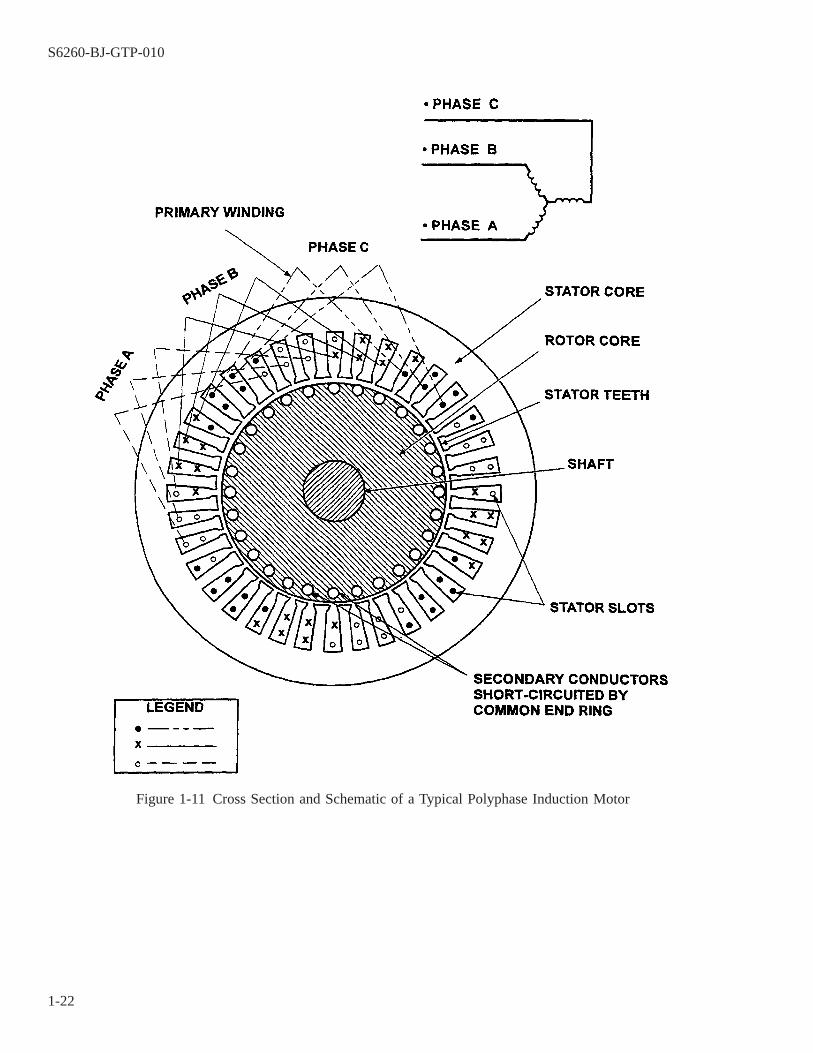
Figure 1-11 Cross Section and Schematic of a Typical Polyphase Induction Motor
S6260-BJ-GTP-010
1-22
CHAPTER 2
TEST EQUIPMENT AND MEASURING INSTRUMENTS
2-1. SCOPE.
This chapter contains descriptions of and operating procedures for typical electrical test equipment andmechanical measuring instruments. Topics include:
2-1.1 Purposes of typical electrical test equipment (paragraph 2-2).
2-1.2 General Radio megohm bridge, Type 1644A (paragraph 2-4).
2-1.3 General Radio megohmmeter, Type 1863 (paragraph 2-8)
2-1.4 Valhalla digital ohmmeter (paragraph 2-15).
2-1.5 Baker ST112E Surge/DC Hipot tester (paragraph 2-19).
2-1.6 External growler (paragraph 2-24).
2-1.7 Typical clamp-on ammeter (paragraph 2-25).
2-1.8 Typical digital ac/dc clamp-on multimeter (paragraph 2-29).
2-1.9 Strobotac, Type 1531-AB (paragraph 2-33).
2-1.10 Polarization Index (paragraph 2-37).
2-1.11 LEXSECO Core Tester 1081D (paragraph 2-38).
2-1.12 AC dielectric test set, Hipotronics, Inc., Model 710-1 (paragraph 2-39).
2-1.13 AC and DC dielectric test set, Hipotronics, Inc., Model 115-A (paragraph 2-45).
2-1.14 Typical dial indicator (paragraph 2-53).
2-1.15 Typical bore gage and ring master (paragraph 2-58).
2-1.16 Typical snap gage (paragraph 2-62).
2-2. PURPOSES OF TYPICAL ELECTRICAL TEST EQUIPMENT.
2-3.
Electrical tests of the windings in a motor or generator are an important part of diagnosing problems andmeeting quality assurance requirements. Electrical tests are performed in place, on receipt in the shop, or afterrewinding or reconditioning. The types of tests discussed in this manual are as follows:
2-3.1 Measurement of Insulation Resistance. Insulation resistance is a measure of the resistance to currentleakage around or through an insulating material. Measurement of insulation resistance in an electrical motor istaken between the windings and the frame. The frame is normally grounded. The purpose of the measurement isto determine the general effectiveness of the insulating material. The megohm bridge or the megohmmeter is rec-ommended for shop use in making this measurement. The hand-cranked megohm tester frequently used for thispurpose does not provide for accurate measurement of high values of insulation resistance.
S6260-BJ-GTP-010
2-1
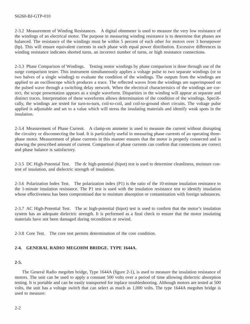
2-3.2 Measurement of Winding Resistances. A digital ohmmeter is used to measure the very low resistance ofthe windings of an electrical motor. The purpose in measuring winding resistance is to determine that phases arebalanced. The resistance of the windings must be within 5 percent of each other for motors over 3 horsepower(hp). This will ensure equivalent currents in each phase with equal power distribution. Excessive differences inwinding resistance indicates shorted turns, an incorrect number of turns, or high resistance connections.
2-3.3 Phase Comparison of Windings. Testing motor windings by phase comparison is done through use of thesurge comparison tester. This instrument simultaneously applies a voltage pulse to two separate windings (or totwo halves of a single winding) to evaluate the condition of the windings. The outputs from the windings areapplied to an oscilloscope which produces a trace. The reflected waves from the windings are superimposed onthe pulsed wave through a switching delay network. When the electrical characteristics of the windings are cor-rect, the scope presentation appears as a single waveform. Disparities in the winding will appear as separate anddistinct traces. Interpretation of these waveforms allows determination of the condition of the windings. Specifi-cally, the windings are tested for turn-to-turn, coil-to-coil, and coil-to-ground short circuits. The voltage pulseapplied is adjustable and set to a value which will stress the insulating materials and identify weak spots in theinsulation.
2-3.4 Measurement of Phase Current. A clamp-on ammeter is used to measure the current without disruptingthe circuitry or disconnecting the load. It is particularly useful in measuring phase currents of an operating three-phase motor. Measurement of phase currents in this manner ensures that the motor is properly connected and isdrawing the prescribed amount of current. Comparison of phase currents can confirm that connections are correctand phase balance is satisfactory.
2-3.5 DC High-Potential Test. The dc high-potential (hipot) test is used to determine cleanliness, moisture con-tent of insulation, and dielectric strength of insulation.
2-3.6 Polarization Index Test. The polarization index (P1) is the ratio of the 10-minute insulation resistance tothe 1-minute insulation resistance. The P1 test is used with the insulation resistance test to identify insulationwhose effectiveness has been compromised due to moisture absorption or contamination with foreign substances.
2-3.7 AC High-Potential Test. The ac high-potential (hipot) test is used to confirm that the motor’s insulationsystem has an adequate dielectric strength. It is performed as a final check to ensure that the motor insulatingmaterials have not been damaged during recondition or rewind.
2-3.8 Core Test. The core test permits determination of the core condition.
2-4. GENERAL RADIO MEGOHM BRIDGE. TYPE 1644A.
2-5.
The General Radio megohm bridge, Type 1644A (figure 2-1), is used to measure the insulation resistance ofmotors. The unit can be used to apply a constant 500 volts over a period of time allowing dielectric absorptiontesting. It is portable and can be easily transported for inplace troubleshooting. Although motors are tested at 500volts, the unit has a voltage switch that can select as much as 1,000 volts. The type 1644A megohm bridge isused to measure:
S6260-BJ-GTP-010
2-2
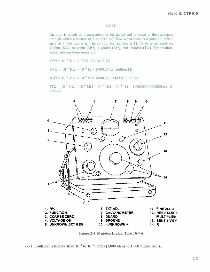
NOTE
An ohm is a unit of measurement of resistance and is equal to the resistancethrough which a current of 1 ampere will flow when there is a potential differ-ence of 1 volt across it. The symbol for an ohm is Ω. Other terms used arekilohm (KΩ). megohm (MΩ), gigaohm (GΩ), and teraohm (TΩ). The relation-ships between these terms are:
1KΩ = 10 3 Ω = 1,000Ω (thousand Ω)
1MΩ = 10 3 KΩ = 10 6 Ω = 1,000,000Ω (million Ω)
1GΩ = 10 3 MΩ = 10 9 Ω = 1,000,000,000Ω (billion Ω)
1TΩ = 10 3 GΩ = 10 6 MΩ = 10 9 KΩ = 10 12 Ω = 1,000,000,000,000Ω) (tril-lion Ω)
2-5.1 Insulation resistance from 10 3 to 10 15 ohms (1,000 ohms to 1,000 trillion ohms).
Figure 2-1 Megohm Bridge, Type 1644A
S6260-BJ-GTP-010
2-3

2-5.2 Leakage resistance of capacitors.
2-6. CONTROLS AND CONNECTORS.
Figure 2-1 shows the front panel controls and connectors of the Type 1644A megohm bridge. Table 2-1 liststhe functions of each control and connector.
Table 2-1 General Radio Megohm Bridge, Type 1644A, Controls andConnectors
FIGURE 2-1REF. NO. NAME TYPE FUNCTION
1 ΔR% Pushbutton switch Continuousrotary control with dial
Inserts R% adjustment in the measurement cir-cuit. Balances bridge ± 5% range
2 FUNCTION 5-position rotary control Turns instrument on and off, selects DIS-CHARGE, CHARGE-ZERO, or MEASUREfunction.
3 COARSE ZERO Continuous rotary control For coarse zero adjustment of detector.4 VOLTAGE ON
UNKNOWN8-position rotary control Selects magnitude of internal voltage applied to
the unknown or connects an external voltagesource.
5 EXT GEN Pair of insulated binding posts For connection of an external voltage supply.6 EXT ADJ Pair of insulated binding posts For connection of a resistor to adjust the voltage
applied to the unknown to values between thosesupplied.
7 GALVANOMETER Mirror-back center-scale gal-vanometer
Indicates balance of bridge.
8 FINE ZERO Continuous rotary control For sensitive zero adjustment of detector.9 GUARD Insulated binding post For connection to points to be guarded, such as
shields of leads.10 GROUND Uninsulated binding post Ground connection to instrument chassis.11 -UNKNOWN+ Pair of insulated binding posts For connection of component to be measured.12 RESISTANCE
MULTIPLIER10-position rotary control Selects the measurement range.
13 SENSITIVITY Continuous rotary control Adjusts the sensitivity of the detector circuit.14 R Continuous rotary control with
dialBalances bridge.
2-7. OPERATION.
To operate the Type 1644A megohm bridge:
NOTE
The covers are not removable. Do not attempt to separate the cover from the unit.
a. Open the instrument case.
(1) Place the case’s rubber feet on a flat surface with the handle away from the operator.
S6260-BJ-GTP-010
2-4
NOTE
Do not force the case open.
(2) Pull the handle locks toward the operator.
(3) Push the handle all the way down.
(4) Balance the side closest to the operator with one hand. With the other hand, tilt the instrument up to aconvenient reading position.
CAUTION
Do not slide the instrument along the cover gasket. Sliding will damage thegasket.
(5) Let the handle rise and the instrument come to rest on the cover gasket.
WARNING
High voltages may be present at any of the red binding posts, depending onthe switch settings. Handle this instrument carefully.
NOTE
The instrument must have a grounded power cord for shipboard use.
″UNKNOWN″ in the context below refers to the component being tested.
b. Connect the grounding link between the UNKNOWN terminal posts and the metal ground post, if a groundedconnection is desired (figure 2-2).
(1) The ungrounded connection is preferred when the component being tested is small and separate, or whenit is mounted in a guarded enclosure. A guarded enclosure is one that is protected from buildup of poten-tial.
(2) The grounded connection is preferred if one terminal of the component being tested must be grounded,or if it is a large, exposed surface, such as a motor frame.
S6260-BJ-GTP-010
2-5

WARNING
DANGER: This instrument provides a high test voltage and can be danger-ous to personnel. Particular care should be used in the measurement ofcapacitor leakage because LETHAL VOLTAGE may be stored in the capaci-tor being tested. Always set the function switch to discharge before connect-ing or disconnecting a component.
c. Turn the function switch from POWER OFF to DISCHARGE. Allow 15 minutes for warmup.
d. Select 500 V (volts) test voltage with the VOLTAGE ON UNKNOWN switch.
NOTE
Avoid changing the test voltage when the function switch is in the MEASUREposition. This will severely overload the detector amplifier, which will thenrequire several minutes to recover.
e. Connect the component to be measured to the + UNKNOWN terminal with the - UNKNOWN terminal con-nected to the motor frame.
f. Set the RESISTANCE MULTIPLIER switch to the 1K range.
g. Set the SENSITIVITY control fully clockwise for measurements either at the highest ranges or at low volt-ages. Set it halfway (arrow up) for other measurements.
h. Set the function switch to CHARGE-ZERO. Adjust the COARSE ZERO and then the FINE ZERO controlsfor a meter zero (NULL).
Figure 2-2 Grounding Link Connection, Megohm Bridge, Type 1644A
S6260-BJ-GTP-010
2-6
NOTE
Insulation resistance should be read after voltage has been applied for 1 minuteand should be in accordance with table 7-2.
i. Set the function switch to MEASURE with the RESISTANCE MULTIPLIER switch on 1K and the main Rdial at its lowest (0.9) reading.
CAUTION
A left deflection of the needle at this setting means that there is a ground orshort and no further measurement is possible. Secure the test at once.
j. When measuring the insulation resistance of operational motors, the RESISTANCE MULTIPLIER switchshould be rotated until a left deflection of the meter needle is obtained. Then return the RESISTANCE MUL-TIPLIER switch to the next lowest range. Adjust the R dial to obtain a null.
k. The value in ohms of the unknown resistance is the dial reading at null multiplied by the quantity indicatedon the RESISTANCE MULTIPLIER dial.
l. Return the function switch to DISCHARGE and remove the component measured.
m. Turn the function switch to POWER OFF.
n. Disconnect and restow the power cord and instrument leads.
o. Close the instrument case and return it to stowage.
2-8. GENERAL RADIO MEGOHMMETER, TYPE 1863.
2-9.
The General Radio megohmmeter, Type 1863 (figure 2-3 and figure 2-4), may be used for insulation resis-tance measurements in place of the megohm bridge, Type 1644A. The Type 1863 is smaller than the Type 1644Aand has simpler controls. The compactness of the unit makes it more desirable for in-place troubleshooting. Themaximum voltage available from this instrument is 500 volts. Guard and ground terminals permit measurementof grounded or ungrounded two- or three-terminal connectors.
S6260-BJ-GTP-010
2-7

2-10. RANGE.
The Type 1863 megohmmeter indicates directly on the panel meter any resistance from 0.5 to 2,000,000megohms. These ranges are suitable for insulation resistance measurements of most types of insulation used inelectrical machinery and electronic components. The voltage applied to the unknown may be 50, 100, 200, 250,or 500 V from the Type 1863, as selected by the TEST VOLTAGE switch on the front panel. The 500-volt levelis a standard value in measurement of the insulation resistance of rotating machinery.
Figure 2-3 Megohmmeter, Type 1863 (Front)
S6260-BJ-GTP-010
2-8

2-11. CONTROLS AND CONNECTORS.
Figure 2-3 shows the front panel controls and connectors of the Type 1863 megohmmeter. Table 2-2 lists andidentifies them. Figure 2-4 shows the rear panel controls and connectors. Table 2-3 lists and identifies them.
2-12. PREPARATION.
To prepare the Type 1863 megohmmeter for operation, open the instrument case as follows:
a. Place the case’s rubber feet on a flat surface with the handle away from the operator.
Figure 2-4 Megohmmeter, Type 1863 (Rear)
S6260-BJ-GTP-010
2-9

NOTE
Do not force the case open.
b. Push down on the handle and the instrument, located in the upper case, will rotate to a vertical position.
c. Hold the handle down with one hand and rotate the instrument to the desired position with the other hand.
CAUTION
Do not slide the instrument along the gasket. This will tear the gasket.
d. Let the handle rise and the instrument come to rest on the cover gasket.
Table 2-2 General Radio Megohmmeter, Type 1863, Front Panel Controlsand Connectors
FIGURE 2-3REF. NO. NAME TYPE FUNCTION
1 POWER 2-position toggle switch Turns power on and off.2 TEST VOLTAGE 5-position rotary switch Selects the test voltage as 50, 100, 200, 250,
or 500 V.3 METER 4-in. meter with plastic cover Indicates the value to be multiplied by the
multiplier switch.4 SET ∞ HIGHEST
RANGEScrewdriver-rotated control Adjusts high end of meter scale on highest
resistance range to compensate for offset cur-rent.
5 SET ∞ Screwdriver-rotated control Adjusts high end of meter scale to compensatefor offset voltage in the voltmeter.
6 GUARD Insulated binding post For guarded measurements. The center of thepost is 3/4 inch from the center of the groundposts so that it can accept a shorting link.
7 GROUND Uninsulated binding post Grounds the + unknown or guard. Containscaptive shorting link.
8 +UNKNOWN Insulated binding post Connects the + unknown or guard. Containscaptive shorting link.
9 -UNKNOWN Insulated binding post Connects the side of the unknown to themegohmmeter.
10 MULTIPLIER 7-position rotary switch Selects resistance range.11 DANGER Indicating light shaded red Glows red when the function switch is in the
CHARGE or MEASURE position.12 MEASURE-
CHARGE-DISCHARGE
3-position toggle switch Selects MEASURE, CHARGE, or DIS-CHARGE function.
NOTE
The instrument must have a grounded power cord for shipboard use.
2-13. MEASUREMENT SETUP.
Proceed as follows to set up the Type 1863 for measurement.
S6260-BJ-GTP-010
2-10
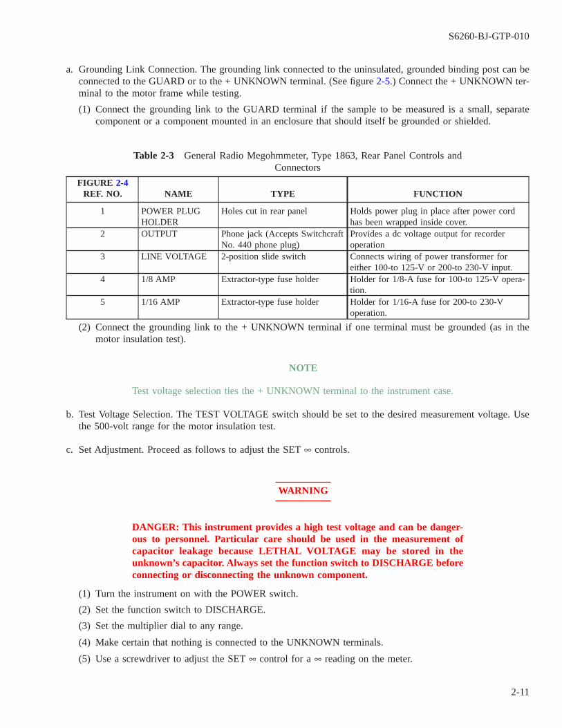
a. Grounding Link Connection. The grounding link connected to the uninsulated, grounded binding post can beconnected to the GUARD or to the + UNKNOWN terminal. (See figure 2-5.) Connect the + UNKNOWN ter-minal to the motor frame while testing.
(1) Connect the grounding link to the GUARD terminal if the sample to be measured is a small, separatecomponent or a component mounted in an enclosure that should itself be grounded or shielded.
Table 2-3 General Radio Megohmmeter, Type 1863, Rear Panel Controls andConnectors
FIGURE 2-4REF. NO. NAME TYPE FUNCTION
1 POWER PLUGHOLDER
Holes cut in rear panel Holds power plug in place after power cordhas been wrapped inside cover.
2 OUTPUT Phone jack (Accepts SwitchcraftNo. 440 phone plug)
Provides a dc voltage output for recorderoperation
3 LINE VOLTAGE 2-position slide switch Connects wiring of power transformer foreither 100-to 125-V or 200-to 230-V input.
4 1/8 AMP Extractor-type fuse holder Holder for 1/8-A fuse for 100-to 125-V opera-tion.
5 1/16 AMP Extractor-type fuse holder Holder for 1/16-A fuse for 200-to 230-Voperation.
(2) Connect the grounding link to the + UNKNOWN terminal if one terminal must be grounded (as in themotor insulation test).
NOTE
Test voltage selection ties the + UNKNOWN terminal to the instrument case.
b. Test Voltage Selection. The TEST VOLTAGE switch should be set to the desired measurement voltage. Usethe 500-volt range for the motor insulation test.
c. Set Adjustment. Proceed as follows to adjust the SET ∞ controls.
WARNING
DANGER: This instrument provides a high test voltage and can be danger-ous to personnel. Particular care should be used in the measurement ofcapacitor leakage because LETHAL VOLTAGE may be stored in theunknown’s capacitor. Always set the function switch to DISCHARGE beforeconnecting or disconnecting the unknown component.
(1) Turn the instrument on with the POWER switch.
(2) Set the function switch to DISCHARGE.
(3) Set the multiplier dial to any range.
(4) Make certain that nothing is connected to the UNKNOWN terminals.
(5) Use a screwdriver to adjust the SET ∞ control for a ∞ reading on the meter.
S6260-BJ-GTP-010
2-11
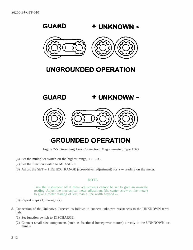
(6) Set the multiplier switch on the highest range, 1T-100G.
(7) Set the function switch to MEASURE.
(8) Adjust the SET ∞ HIGHEST RANGE (screwdriver adjustment) for a ∞ reading on the meter.
NOTE
Turn the instrument off if these adjustments cannot be set to give an on-scalereading. Adjust the mechanical meter adjustment (the center screw on the meter)to give a meter reading of less than a line width beyond ∞.
(9) Repeat steps (1) through (7).
d. Connection of the Unknown. Proceed as follows to connect unknown resistances to the UNKNOWN termi-nals.
(1) Set function switch to DISCHARGE.
(2) Connect small size components (such as fractional horsepower motors) directly to the UNKNOWN ter-minals.
Figure 2-5 Grounding Link Connection, Megohmmeter, Type 1863
S6260-BJ-GTP-010
2-12
NOTE
Insulated leads (GR 274-LSR single plug patch cord) may be connected to anearby unknown resistance. However, if the unknown resistance is high, leakagebetween the leads will cause a measurement error. Stray lead capacitance to thehigh lead will cause a transient meter deflection.
(3) Connect high (and remotely located) resistance measurements with shielded leads.
2-14. MEASUREMENT PROCEDURE.
Either of two measurement procedures may be used, depending on whether the correct resistance-multiplierrange is known. If the range is not known, the search procedure should be followed. The sort procedure shouldbe used if repetitive measurements will be made on a given range (that is, if similar components are to be sorted).
a. Search Procedure. Proceed as follows when the approximate resistance of the component to be measured isnot known:
(1) Set the multiplier switch to the lowest range.
(2) Set the function switch to DISCHARGE.
(3) Connect the ground terminal to the + UNKNOWN terminal using the grounding connection (figure 2-5).
(4) Connect the component to be measured to the + and - UNKNOWN terminals.
(a) Use a shielded lead for remote measurements.
(b) Use the shorting link.
(c) Shield the + UNKNOWN terminal.
(d) Tie the shield to the GUARD terminal.
(5) Set the function switch to MEASURE.
(6) Measure after voltage has been applied for 1 minute.
(7) Rotate the multiplier switch clockwise until the meter gives a reading of less than 5.
NOTE
The resistance of the unknown is the meter reading multiplied by the multiplier-dial indication.
b. Sort Procedure. Proceed as follows when the approximate resistance of the component is known.
(1) Set the function switch to DISCHARGE.
(2) Set the multiplier switch to the desired range.
(3) Connect the component between the + and - UNKNOWN terminals.
(4) Set the function switch to MEASURE.
(5) Measure after voltage has been applied for 1 minute.
NOTE
The resistance of the unknown is the meter reading multiplied by the multiplier-switch indication.
For go-no-go checks, it is often useful to make a limit line on the outside of themeter case with a strip of masking tape.
S6260-BJ-GTP-010
2-13
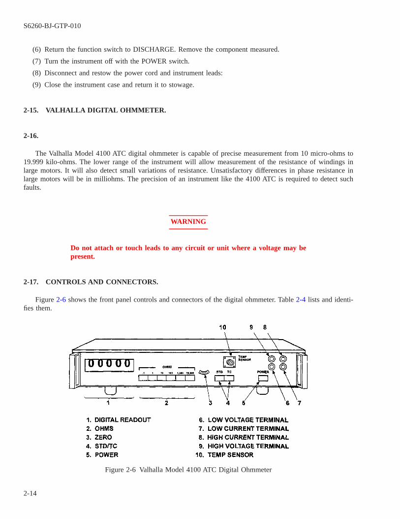
(6) Return the function switch to DISCHARGE. Remove the component measured.
(7) Turn the instrument off with the POWER switch.
(8) Disconnect and restow the power cord and instrument leads:
(9) Close the instrument case and return it to stowage.
2-15. VALHALLA DIGITAL OHMMETER.
2-16.
The Valhalla Model 4100 ATC digital ohmmeter is capable of precise measurement from 10 micro-ohms to19.999 kilo-ohms. The lower range of the instrument will allow measurement of the resistance of windings inlarge motors. It will also detect small variations of resistance. Unsatisfactory differences in phase resistance inlarge motors will be in milliohms. The precision of an instrument like the 4100 ATC is required to detect suchfaults.
WARNING
Do not attach or touch leads to any circuit or unit where a voltage may bepresent.
2-17. CONTROLS AND CONNECTORS.
Figure 2-6 shows the front panel controls and connectors of the digital ohmmeter. Table 2-4 lists and identi-fies them.
Figure 2-6 Valhalla Model 4100 ATC Digital Ohmmeter
S6260-BJ-GTP-010
2-14
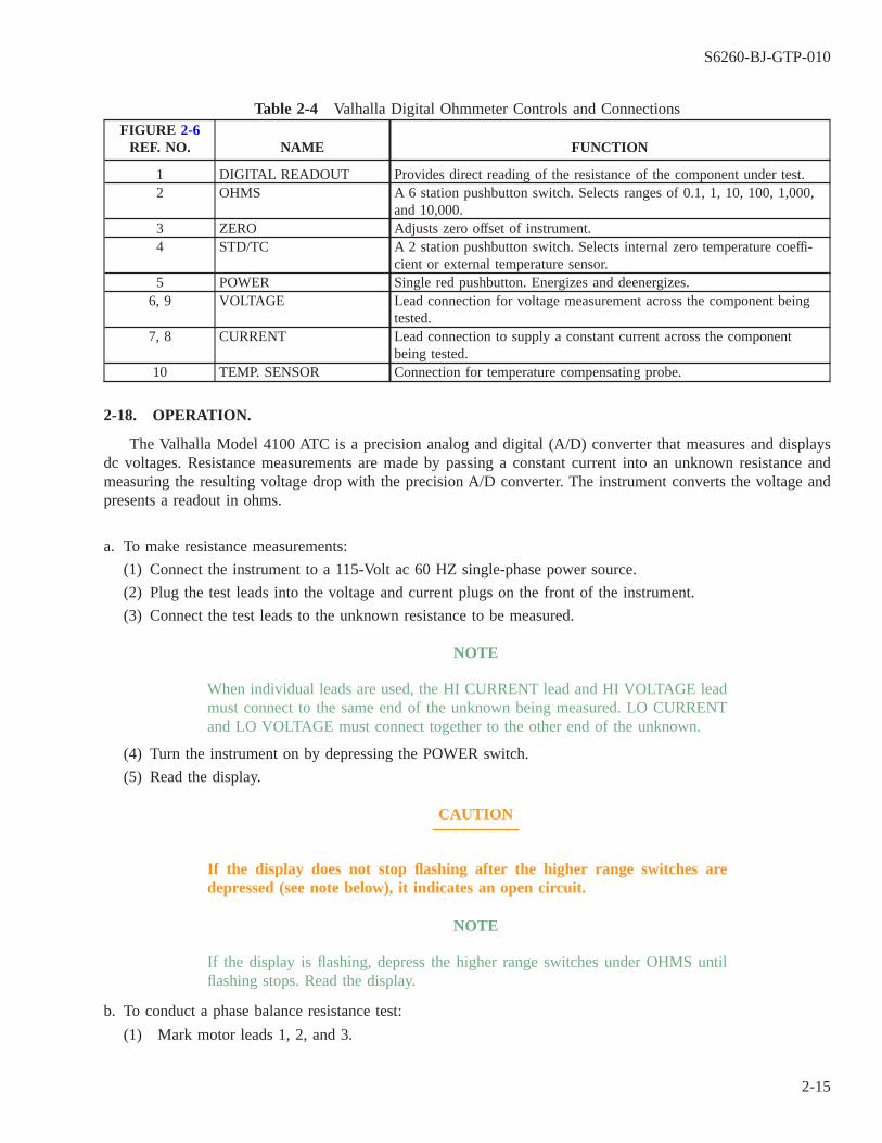
Table 2-4 Valhalla Digital Ohmmeter Controls and ConnectionsFIGURE 2-6
REF. NO. NAME FUNCTION
1 DIGITAL READOUT Provides direct reading of the resistance of the component under test.2 OHMS A 6 station pushbutton switch. Selects ranges of 0.1, 1, 10, 100, 1,000,
and 10,000.3 ZERO Adjusts zero offset of instrument.4 STD/TC A 2 station pushbutton switch. Selects internal zero temperature coeffi-
cient or external temperature sensor.5 POWER Single red pushbutton. Energizes and deenergizes.
6, 9 VOLTAGE Lead connection for voltage measurement across the component beingtested.
7, 8 CURRENT Lead connection to supply a constant current across the componentbeing tested.
10 TEMP. SENSOR Connection for temperature compensating probe.
2-18. OPERATION.
The Valhalla Model 4100 ATC is a precision analog and digital (A/D) converter that measures and displaysdc voltages. Resistance measurements are made by passing a constant current into an unknown resistance andmeasuring the resulting voltage drop with the precision A/D converter. The instrument converts the voltage andpresents a readout in ohms.
a. To make resistance measurements:
(1) Connect the instrument to a 115-Volt ac 60 HZ single-phase power source.
(2) Plug the test leads into the voltage and current plugs on the front of the instrument.
(3) Connect the test leads to the unknown resistance to be measured.
NOTE
When individual leads are used, the HI CURRENT lead and HI VOLTAGE leadmust connect to the same end of the unknown being measured. LO CURRENTand LO VOLTAGE must connect together to the other end of the unknown.
(4) Turn the instrument on by depressing the POWER switch.
(5) Read the display.
CAUTION
If the display does not stop flashing after the higher range switches aredepressed (see note below), it indicates an open circuit.
NOTE
If the display is flashing, depress the higher range switches under OHMS untilflashing stops. Read the display.
b. To conduct a phase balance resistance test:
(1) Mark motor leads 1, 2, and 3.
S6260-BJ-GTP-010
2-15

(2) Locate the 4100 ATC next to the motor.
(3) Connect the 4100 ATC to a 115-volt ac, 60-Hz single-phase power source.
(4) Connect the instrument leads to the terminal post on the instrument.
(5) Connect the instrument leads to leads 1 and 2 on the motor to be tested.
NOTE
When individual leads are used, the HI CURRENT lead and HI VOLTAGE leadmust connect to the same end of the unknown being measured. LO CURRENTand LO VOLTAGE must connect together to the other end of the unknown.
(6) Select the instrument range by depressing the proper selector under OHMS.
(7) Depress the STD switch.
(8) Depress the POWER switch to turn the instrument on
(9) Read the display.
CAUTION
If the display does not stop flashing after the higher range switches aredepressed (see note below), it indicates an open circuit.
NOTE
If the display is flashing, depress the higher range switches under OHMS untilflashing stops. Read the display.
(10) Record the reading on a motor data sheet (electrical) (figure 2-7) in the appropriate section.
(11) Disconnect the instrument leads attached to motor lead 1 and connect them to motor lead 3.
(12) Repeat steps (6) through (10).
(13) Disconnect the instrument leads attached to motor lead 2 and connect them to motor lead 1.
(14) Repeat steps (6) through (10).
(15) Turn the instrument off.
S6260-BJ-GTP-010
2-16
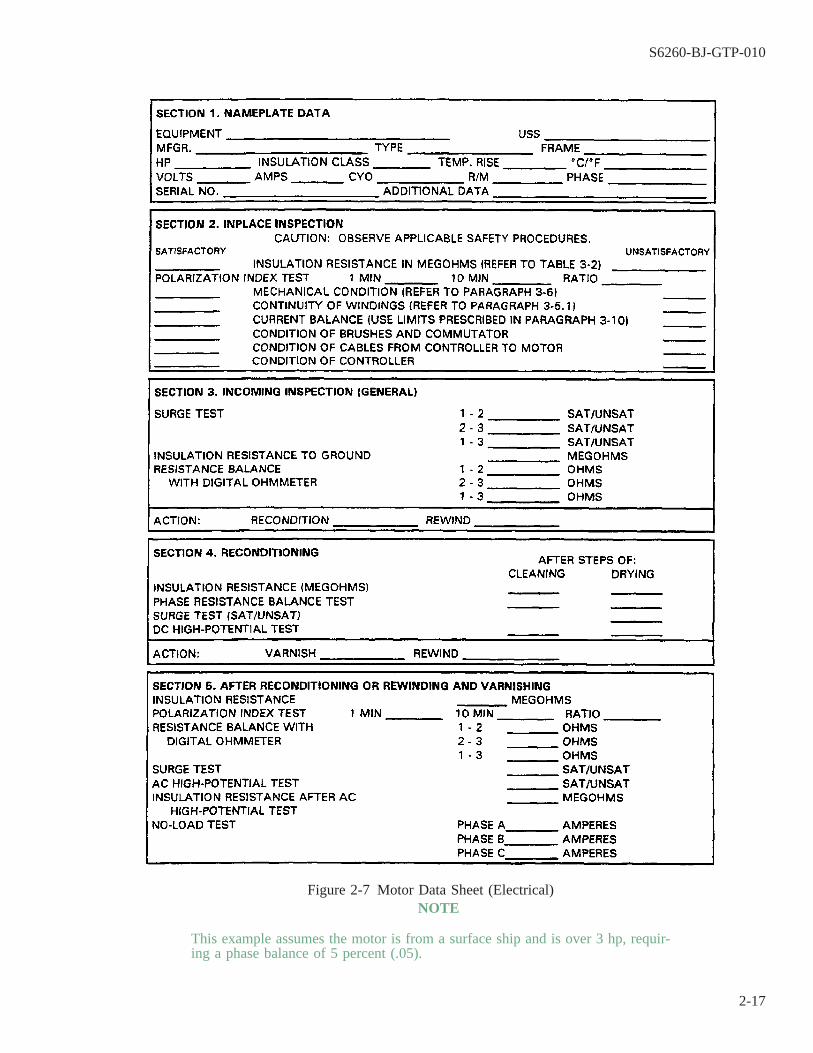
NOTE
This example assumes the motor is from a surface ship and is over 3 hp, requir-ing a phase balance of 5 percent (.05).
Figure 2-7 Motor Data Sheet (Electrical)
S6260-BJ-GTP-010
2-17

c. To calculate motor winding difference:
(1) Assume the readings taken using the 4100 ATC were recorded on the motor data sheet as follows:Phase resistance balance 1-2 0.325 ohms
2-3 0.326 ohms3-1 0.333 ohms
(2) Multiply the highest reading by 0.05. The figure calculated is the maximum imbalance allowed betweenphases.
(3) Subtract the lowest reading from the highest reading.
(4) The motor must be rewound when the difference between the high and low reading exceeds the calculatedallowable imbalance. In the example, the maximum imbalance allowed was 0.01665 ohms. The actualdifference was 0.008 ohms. The difference is less than allowed. Therefore, the winding is good.
2-19. BAKER ST112E SURGE/DC HIGH-POTENTIAL TESTER.
2-20.
The Baker ST112E Surge/DC high-potential tester is used to detect defective insulation and winding errorsin all types of coils. When used as a surge comparison tester, the tester uses a comparison method for detectingwinding faults. Each pair of windings is compared by alternately applying the test voltage to each winding. Theresulting waveform from both windings is displayed on an oscilloscope (figure 2-8 and figure 2-9). Waveformcan be affected by winding designs and will often indicate a fault, but this is actually an induction difference.This occurs in coupling between windings in a two-speed, two-winding motor and also on concentric (basket)windings. The Baker ST112E is also a dc high-potential tester. DC high-potential tests are made by applying dcvoltage in steps and recording leakage current (microamperes) through the insulation. The voltage and currentare plotted on graph paper and the shape of the resultant curve is used for checking the cleanliness and moisturecontent of the machine tested. The dc high-potential test should be used during overhaul to determine cleanlinessand moisture content of insulation before or during reconditioning of equipment, since it is less destructive thanac high-potential testing. The dc high-potential test can also be used at a reduced voltage as a preventive ortroubleshooting technique.
S6260-BJ-GTP-010
2-18
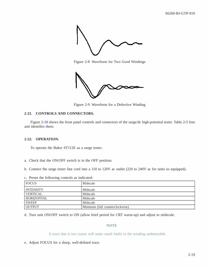
2-21. CONTROLS AND CONNECTORS.
Figure 2-10 shows the front panel controls and connectors of the surge/dc high-potential tester. Table 2-5 listsand identifies them.
2-22. OPERATION.
To operate the Baker ST112E as a surge tester:
a. Check that the ON/OFF switch is in the OFF position.
b. Connect the surge tester line cord into a 110 to 120V ac outlet (220 to 240V ac for units so equipped).
c. Preset the following controls as indicated:
FOCUS Midscale
INTENSITY MidscaleVERTICAL MidscaleHORIZONTAL MidscaleSWEEP MidscaleOUTPUT Minimum (full counterclockwise)
d. Turn unit ON/OFF switch to ON (allow brief period for CRT warm-up) and adjust to midscale.
NOTE
A trace that is too coarse will make small faults in the winding undetectable.
e. Adjust FOCUS for a sharp, well-defined trace.
Figure 2-8 Waveform for Two Good Windings
Figure 2-9 Waveform for a Defective Winding
S6260-BJ-GTP-010
2-19
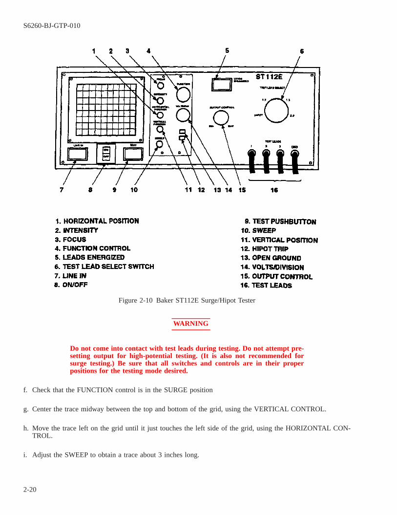
WARNING
Do not come into contact with test leads during testing. Do not attempt pre-setting output for high-potential testing. (It is also not recommended forsurge testing.) Be sure that all switches and controls are in their properpositions for the testing mode desired.
f. Check that the FUNCTION control is in the SURGE position
g. Center the trace midway between the top and bottom of the grid, using the VERTICAL CONTROL.
h. Move the trace left on the grid until it just touches the left side of the grid, using the HORIZONTAL CON-TROL.
i. Adjust the SWEEP to obtain a trace about 3 inches long.
Figure 2-10 Baker ST112E Surge/Hipot Tester
S6260-BJ-GTP-010
2-20
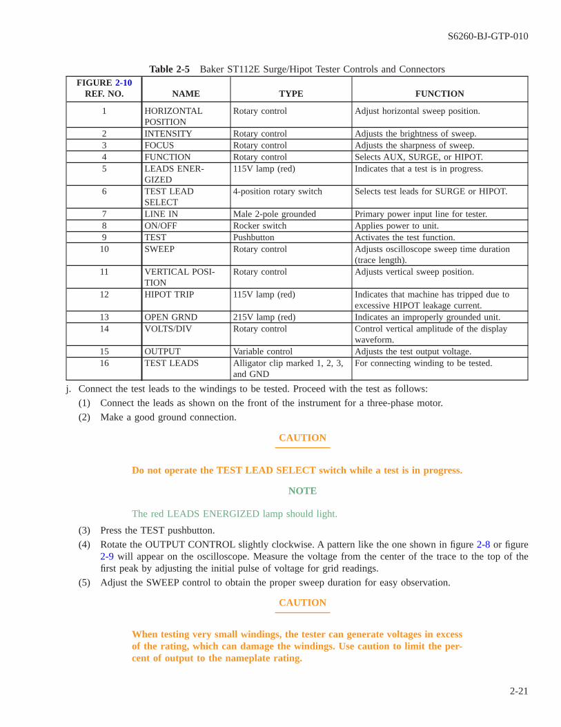
Table 2-5 Baker ST112E Surge/Hipot Tester Controls and ConnectorsFIGURE 2-10
REF. NO. NAME TYPE FUNCTION
1 HORIZONTALPOSITION
Rotary control Adjust horizontal sweep position.
2 INTENSITY Rotary control Adjusts the brightness of sweep.3 FOCUS Rotary control Adjusts the sharpness of sweep.4 FUNCTION Rotary control Selects AUX, SURGE, or HIPOT.5 LEADS ENER-
GIZED115V lamp (red) Indicates that a test is in progress.
6 TEST LEADSELECT
4-position rotary switch Selects test leads for SURGE or HIPOT.
7 LINE IN Male 2-pole grounded Primary power input line for tester.8 ON/OFF Rocker switch Applies power to unit.9 TEST Pushbutton Activates the test function.10 SWEEP Rotary control Adjusts oscilloscope sweep time duration
(trace length).11 VERTICAL POSI-
TIONRotary control Adjusts vertical sweep position.
12 HIPOT TRIP 115V lamp (red) Indicates that machine has tripped due toexcessive HIPOT leakage current.
13 OPEN GRND 215V lamp (red) Indicates an improperly grounded unit.14 VOLTS/DIV Rotary control Control vertical amplitude of the display
waveform.15 OUTPUT Variable control Adjusts the test output voltage.16 TEST LEADS Alligator clip marked 1, 2, 3,
and GNDFor connecting winding to be tested.
j. Connect the test leads to the windings to be tested. Proceed with the test as follows:
(1) Connect the leads as shown on the front of the instrument for a three-phase motor.
(2) Make a good ground connection.
CAUTION
Do not operate the TEST LEAD SELECT switch while a test is in progress.
NOTE
The red LEADS ENERGIZED lamp should light.
(3) Press the TEST pushbutton.
(4) Rotate the OUTPUT CONTROL slightly clockwise. A pattern like the one shown in figure 2-8 or figure2-9 will appear on the oscilloscope. Measure the voltage from the center of the trace to the top of thefirst peak by adjusting the initial pulse of voltage for grid readings.
(5) Adjust the SWEEP control to obtain the proper sweep duration for easy observation.
CAUTION
When testing very small windings, the tester can generate voltages in excessof the rating, which can damage the windings. Use caution to limit the per-cent of output to the nameplate rating.
S6260-BJ-GTP-010
2-21
NOTE
The test voltage should be (2 E +1000) x 1.4 for new windings. E is the ratedvoltage of the machine. Reconditioned windings should be 2/3((2E + 1000) x1.4).
(6) Adjust the OUTPUT CONTROL switch for the desired test voltage.
CAUTION
Do not operate the tester with a vertical display that exceeds the size of theCRT grid.
(7) Adjust the VOLTS/DIV to keep the waveform on the CRT grid when the OUTPUT CONTROL isincreased.
(8) Release the TEST button. Rotate the TEST LEAD SELECT switch to the next position. Repeat until allthree TEST LEAD SELECT positions have been selected.
(9) Compare the observed waveform with figure 2-11 to determine the type of fault when faults are indi-cated.
(10) Enter the results on the motor data sheet (electrical) (figure 2-7) when the surge test has been completed.
k. The following data must be considered in conducting any test comparing observed waveforms:
(1) Most testing performed is comparison testing in which the inductance of two identical windings (or twowindings of a three-phase winding) are tested simultaneously. The output waveforms are comparedagainst each other.
(2) The tester can be used to test for voltage breakdown of a single winding. However, results are difficultto judge due to lack of a comparison.
(3) A single waveshape will result when two matched windings with no faults are being tested.
S6260-BJ-GTP-010
2-22
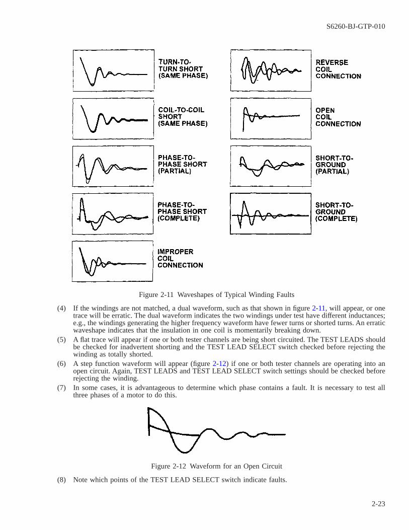
(4) If the windings are not matched, a dual waveform, such as that shown in figure 2-11, will appear, or onetrace will be erratic. The dual waveform indicates the two windings under test have different inductances;e.g., the windings generating the higher frequency waveform have fewer turns or shorted turns. An erraticwaveshape indicates that the insulation in one coil is momentarily breaking down.
(5) A flat trace will appear if one or both tester channels are being short circuited. The TEST LEADS shouldbe checked for inadvertent shorting and the TEST LEAD SELECT switch checked before rejecting thewinding as totally shorted.
(6) A step function waveform will appear (figure 2-12) if one or both tester channels are operating into anopen circuit. Again, TEST LEADS and TEST LEAD SELECT switch settings should be checked beforerejecting the winding.
(7) In some cases, it is advantageous to determine which phase contains a fault. It is necessary to test allthree phases of a motor to do this.
(8) Note which points of the TEST LEAD SELECT switch indicate faults.
Figure 2-11 Waveshapes of Typical Winding Faults
Figure 2-12 Waveform for an Open Circuit
S6260-BJ-GTP-010
2-23
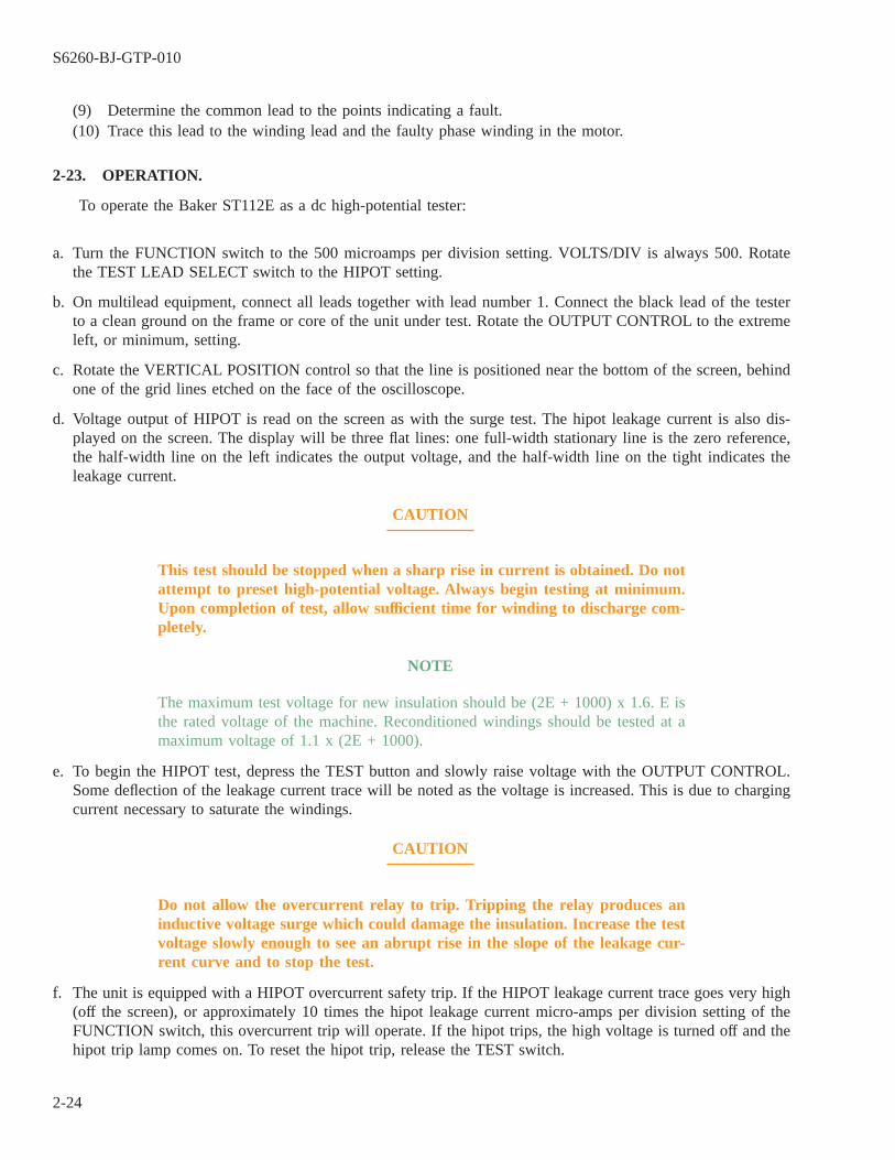
(9) Determine the common lead to the points indicating a fault.(10) Trace this lead to the winding lead and the faulty phase winding in the motor.
2-23. OPERATION.
To operate the Baker ST112E as a dc high-potential tester:
a. Turn the FUNCTION switch to the 500 microamps per division setting. VOLTS/DIV is always 500. Rotatethe TEST LEAD SELECT switch to the HIPOT setting.
b. On multilead equipment, connect all leads together with lead number 1. Connect the black lead of the testerto a clean ground on the frame or core of the unit under test. Rotate the OUTPUT CONTROL to the extremeleft, or minimum, setting.
c. Rotate the VERTICAL POSITION control so that the line is positioned near the bottom of the screen, behindone of the grid lines etched on the face of the oscilloscope.
d. Voltage output of HIPOT is read on the screen as with the surge test. The hipot leakage current is also dis-played on the screen. The display will be three flat lines: one full-width stationary line is the zero reference,the half-width line on the left indicates the output voltage, and the half-width line on the tight indicates theleakage current.
CAUTION
This test should be stopped when a sharp rise in current is obtained. Do notattempt to preset high-potential voltage. Always begin testing at minimum.Upon completion of test, allow sufficient time for winding to discharge com-pletely.
NOTE
The maximum test voltage for new insulation should be (2E + 1000) x 1.6. E isthe rated voltage of the machine. Reconditioned windings should be tested at amaximum voltage of 1.1 x (2E + 1000).
e. To begin the HIPOT test, depress the TEST button and slowly raise voltage with the OUTPUT CONTROL.Some deflection of the leakage current trace will be noted as the voltage is increased. This is due to chargingcurrent necessary to saturate the windings.
CAUTION
Do not allow the overcurrent relay to trip. Tripping the relay produces aninductive voltage surge which could damage the insulation. Increase the testvoltage slowly enough to see an abrupt rise in the slope of the leakage cur-rent curve and to stop the test.
f. The unit is equipped with a HIPOT overcurrent safety trip. If the HIPOT leakage current trace goes very high(off the screen), or approximately 10 times the hipot leakage current micro-amps per division setting of theFUNCTION switch, this overcurrent trip will operate. If the hipot trips, the high voltage is turned off and thehipot trip lamp comes on. To reset the hipot trip, release the TEST switch.
S6260-BJ-GTP-010
2-24
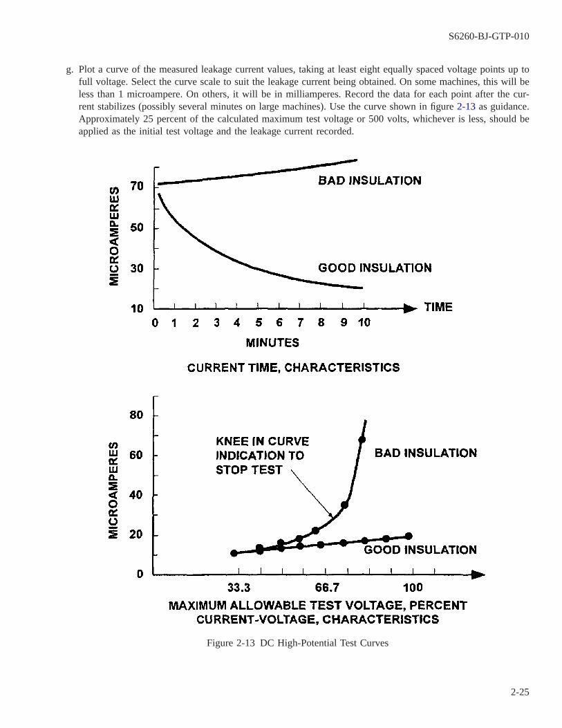
g. Plot a curve of the measured leakage current values, taking at least eight equally spaced voltage points up tofull voltage. Select the curve scale to suit the leakage current being obtained. On some machines, this will beless than 1 microampere. On others, it will be in milliamperes. Record the data for each point after the cur-rent stabilizes (possibly several minutes on large machines). Use the curve shown in figure 2-13 as guidance.Approximately 25 percent of the calculated maximum test voltage or 500 volts, whichever is less, should beapplied as the initial test voltage and the leakage current recorded.
Figure 2-13 DC High-Potential Test Curves
S6260-BJ-GTP-010
2-25

2-24. EXTERNAL GROWLER.
NOTE
There are several models of growlers. They may or may not have on/offswitches, indicator lights, test leads, or meters. The growler described below istypical.
2-24.1 A growler is used to test for short circuits in dc armatures or for loose bars in ac squirrel cage motors.The growler comes as both internal and external (figure 2-14) models. Table 2-6 lists and describes the controlsand connectors of a generic external growler. Both models operate in a similar manner. The internal growler ishand held and used to test the condition of large stators, particularly ac generators. The V-type external growleris used to test rotors and armatures. This growler may range in size from a bench model to a large floor modelon wheels.
NOTE
Bench-type growlers with optional installed millivoltmeter and test leads mayalso be used to test for insulation resistance to ground and open circuits. Consultmanufacturers’ instructions for this use.
Figure 2-14 External Growler
S6260-BJ-GTP-010
2-26
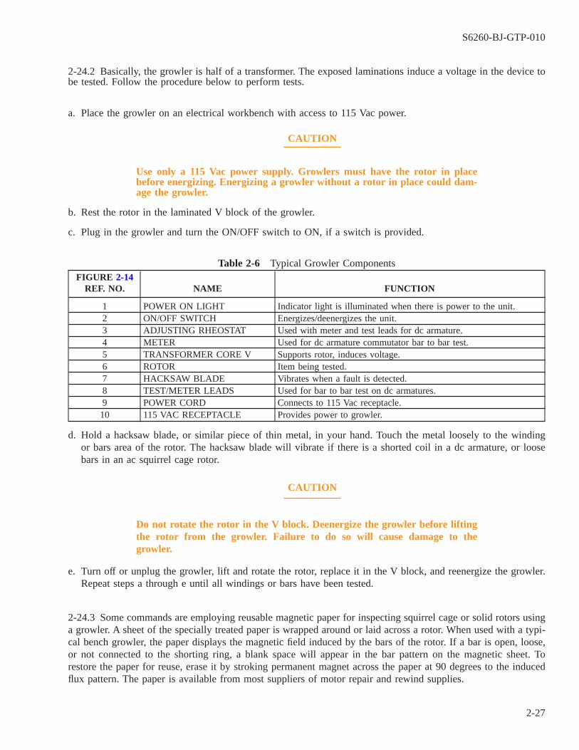
2-24.2 Basically, the growler is half of a transformer. The exposed laminations induce a voltage in the device tobe tested. Follow the procedure below to perform tests.
a. Place the growler on an electrical workbench with access to 115 Vac power.
CAUTION
Use only a 115 Vac power supply. Growlers must have the rotor in placebefore energizing. Energizing a growler without a rotor in place could dam-age the growler.
b. Rest the rotor in the laminated V block of the growler.
c. Plug in the growler and turn the ON/OFF switch to ON, if a switch is provided.
Table 2-6 Typical Growler ComponentsFIGURE 2-14
REF. NO. NAME FUNCTION
1 POWER ON LIGHT Indicator light is illuminated when there is power to the unit.2 ON/OFF SWITCH Energizes/deenergizes the unit.3 ADJUSTING RHEOSTAT Used with meter and test leads for dc armature.4 METER Used for dc armature commutator bar to bar test.5 TRANSFORMER CORE V Supports rotor, induces voltage.6 ROTOR Item being tested.7 HACKSAW BLADE Vibrates when a fault is detected.8 TEST/METER LEADS Used for bar to bar test on dc armatures.9 POWER CORD Connects to 115 Vac receptacle.10 115 VAC RECEPTACLE Provides power to growler.
d. Hold a hacksaw blade, or similar piece of thin metal, in your hand. Touch the metal loosely to the windingor bars area of the rotor. The hacksaw blade will vibrate if there is a shorted coil in a dc armature, or loosebars in an ac squirrel cage rotor.
CAUTION
Do not rotate the rotor in the V block. Deenergize the growler before liftingthe rotor from the growler. Failure to do so will cause damage to thegrowler.
e. Turn off or unplug the growler, lift and rotate the rotor, replace it in the V block, and reenergize the growler.Repeat steps a through e until all windings or bars have been tested.
2-24.3 Some commands are employing reusable magnetic paper for inspecting squirrel cage or solid rotors usinga growler. A sheet of the specially treated paper is wrapped around or laid across a rotor. When used with a typi-cal bench growler, the paper displays the magnetic field induced by the bars of the rotor. If a bar is open, loose,or not connected to the shorting ring, a blank space will appear in the bar pattern on the magnetic sheet. Torestore the paper for reuse, erase it by stroking permanent magnet across the paper at 90 degrees to the inducedflux pattern. The paper is available from most suppliers of motor repair and rewind supplies.
S6260-BJ-GTP-010
2-27

2-24.4 Iron filings can also be used to indicate the condition of rotor bars in conjunction with a growler. Ironfilings are placed on a sheet of paper and the paper is placed on the surface of the rotor. The iron filings willstick through the paper to good bars and will not be attracted to open bars. The rotor shall be rotated in thegrowler’s magnetic field until all the bars have been checked. A LEXSECO core loss tester (paragraph 2-38) orequivalent can be used (in lieu of the growler) to magnetize the core. When using a core loss tester, use a rela-tively low amperage which is just enough to create a flux pattern in the iron filings.
2-24.5 An ammeter, in series with the line cord of the growler, can also be used to check rotor bars. The amme-ter should not show any current variations in excess of 5 percent while the rotor is rotated in the growler’s mag-netic field. Limit the current to the growler to the ammeter’s capability by placing a dropping resistor in thegrowler supply line. Rotate the rotor in the growler for at least two full revolutions to ensure repeatability of thereadings and to ensure that all bars were checked.
2-25. TYPICAL CLAMP-ON AMMETER.
2-26.
The clamp-on ammeter can be used to measure current without connecting any special equipment or disturb-ing the circuit. Clamp-on ammeters may have a capability for voltage measurement as well as resistance mea-surements through the use of external leads.
2-27. CONTROLS AND CONNECTORS.
Figure 2-15 shows typical front panel controls and connectors for the clamp-on ammeter. Table 2-7 lists andidentifies them.
NOTE
Some models of clamp-on ammeters may have more controls than others.
S6260-BJ-GTP-010
2-28

2-28. OPERATION.
To operate the clamp-on ammeter, remove the instrument and the test leads from their case and proceed asfollows:
Table 2-7 Clamp-on Ammeter Controls and Connectors
FIGURE 2-15REF. NO. NAME TYPE FUNCTION
1 TRANSFORMERJAWS
Insulated tapered Jaws; accepts upto 1-3/8 in OD cable
Measures current; snaps around one con-ductor
2 RANGE SELECTOR Rotary switch and dial drummechanism
Selects volt or amp scale.
3 OHMPROBERECEPTACLE
Female; twist-to-lock For connection of ohmmeter test leads.
4 METER SCALE Selectable scale; 0-300 ac amps;0-600 ac volts; 0 ohms; 50-400Hz; ± 3%
Indicates volt, ohm, or amp measure-ments.
5 VOLTAGE RECEP-TACLES
Female; twist-to-lock For connection of voltmeter test leads.
6 OHMMETER ZEROADJ.
Rotary control Zeros meter with test leads shorted.
7 ZERO ADJUST Rotary control Zeros meter for greatest accuracy.
Figure 2-15 Clamp-on Ammeter, Model SPR-300
S6260-BJ-GTP-010
2-29

Table 2-7 Clamp-on Ammeter Controls and Connectors - Continued
FIGURE 2-15REF. NO. NAME TYPE FUNCTION
8 POINTER LOCK Slide-to-lock Freezes pointer when readings are taken.9 TRIGGER Press-to-open Opens transformer jaws.10 OHMPROBE BAT-
TERY/FUSEATTACHMENT(NOT SHOWN)
Sperry type F-1 fuse and Sperrytype B-1 battery
Fuses the OHMPROBE to prevent dam-age to the instrument if a resistance mea-surement is taken on a live circuit.
a. Voltage Measurement.
CAUTION
Remove the OHMPROBE fuse and battery attachment from the instrumentbefore measuring volts. The fuse will burn out if it is not removed.
NOTE
Some models may not have this fuse or feature.
(1) Insert the test lead plugs into the voltage receptacles and twist them clockwise to lock them into position.
(2) Set the range selector switch to the highest voltage range scale.
(3) Unlock the pointer lock.
WARNING
Wear rubber gloves to prevent hand contact with bare conductors.
NOTE
Connect the instrument to a known ″live″ source to ensure proper operationbefore making voltage measurements. Voltage ranges are printed in red.
(4) Connect an alligator clip to any side of the ac line to be measured.
(5) Hold the instrument in one hand and touch the other side of the ac line with the second test lead.
(6) Connect the second alligator clip to the other side of the line and take a voltage reading if the readingdoes not exceed the highest voltage scale.
(7) Set the range selector switch to the next lowest voltage range if the reading is in the lower half of thescale.
(8) Repeat step (7) until the reading is in the upper half of the scale.
b. Current Measurement.
S6260-BJ-GTP-010
2-30

CAUTION
Remove the OHMPROBE fuse and battery attachment from the instrumentbefore measuring amperes. The fuse will burn out if it is not removed.
NOTE
Some models may not have this fuse or feature.
(1) Set the range selector switch to the highest current range scale.
WARNING
Wear rubber gloves to prevent hand contact with bare conductors.
(2) Unlock the pointer lock.
NOTE
Separate the conductors to ensure that the point of attachment is easily accessiblebefore making a current measurement. Be sure that the meter may be attachedand read correctly without contacting ″hot″ wires.
(3) Open the transformer jaws by depressing the trigger.
(4) Snap the transformer jaws around one conductor.
NOTE
Make certain that the transformer jaws are completely closed before a reading istaken.
(5) Set the range selector switch to the next lowest current range if the reading is in the lower half of thescale.
(6) Repeat step (5) until the reading is in the upper half of the scale.
NOTE
The current may be read directly from the meter.
(7) Record the current reading of each phase of the motor under test on the motor data sheet (electrical) (fig-ure 2-7).
(8) Return the instrument to its case after completing the measurement.
2-29. TYPICAL DIGITAL AC/DC CLAMP-ON MULTIMETER.
2-30.
The digital ac/dc clamp-on multimeter can be used to measure ac or dc current in a circuit without connect-ing, disconnecting, or disturbing circuit components or wiring. Modern digital clamp-on digital meters have theability to measure ac and dc voltages, frequency, motor starting current, and duty cycle. They measure resistance
S6260-BJ-GTP-010
2-31
in ohms and have continuity check and diode test capabilities. They have a data hold feature, which locks thereading on the liquid crystal display (LCD) panel for easy interpretation.
NOTE
Some models of clamp-on digital multimeters have more controls than others.
2-31. CONTROLS AND CONNECTORS.
Figure 2-16 shows typical front panel controls and connectors for the clamp-on digital multimeter. Table 2-8lists and identifies them. Table 2-9 identifies and describes the symbols used on the LCD panel.
2-32. OPERATION.
To operate the digital clamp-on multimeter, remove the instrument and the test leads from their case and pro-ceed as follows:
a. AC Current Measurement.
CAUTION
Do NOT connect test leads.
(1) Set the rotary switch to A.
(2) Momentarily press the DC/AC pushbutton to select AC.
(3) Press the handle to open the jaws and clamp them around a single conductor. For the most accurate read-ing, keep the conductor aligned with the centering marks on the jaws.
(4) Read the display.
S6260-BJ-GTP-010
2-32
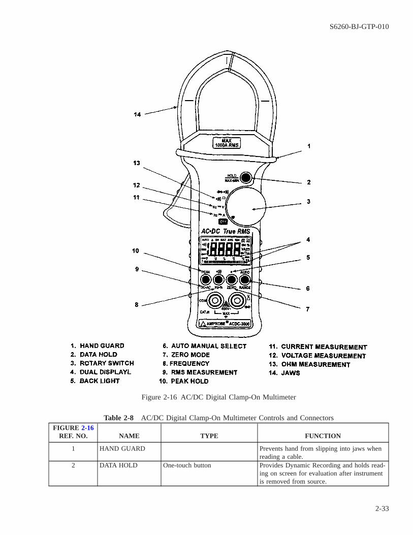
Table 2-8 AC/DC Digital Clamp-On Multimeter Controls and ConnectorsFIGURE 2-16
REF. NO. NAME TYPE FUNCTION
1 HAND GUARD Prevents hand from slipping into jaws whenreading a cable.
2 DATA HOLD One-touch button Provides Dynamic Recording and holds read-ing on screen for evaluation after instrumentis removed from source.
Figure 2-16 AC/DC Digital Clamp-On Multimeter
S6260-BJ-GTP-010
2-33

Table 2-8 AC/DC Digital Clamp-On Multimeter Controls and Connectors -
Continued
FIGURE 2-16REF. NO. NAME TYPE FUNCTION
3 ROTARY SWITCH Rotary selector Selects between modes of measurement: acvolts, dc volts, ac amps, dc amps, ohms,diode, or frequency.
4 DUAL DISPLAY Liquid crystal display (LCD)screen
Panel where readings are observed. Digitaldisplay of frequency/duty cycle and bargraph display of current/voltage.
5 BACKLIGHT Pushbutton When selected, provides backlight LCD dis-play for easier reading in dark areas.
6 AUTO/MANUALSELECT
Two-function pushbutton Selects range. Push to step through the ranger push and hold button to shift to automaticrange selection.
7 ZERO MODE Pushbutton Sets relative zero for deviation measure-ments.
8 FREQUENCY Two-function pushbutton Selects between frequency and duty cyclefunction on and off.
9 RMS MEASURE-MENT
Two-function pushbutton Press to select between ac, dc, or ac+dcmodes. Press and hold to toggle betweenpeak and dc readings.
10 PEAK HOLD Two-function pushbutton Press and hold for 1 second to toggle (seeDC-AC above)
11 CURRENT MEA-SUREMENT
Rotary selector position Selects current operation of meter.
12 VOLTAGE MEA-SUREMENT
Rotary selector position Selects voltage operation of meter.
13 OHM MEASURE-MENT
Rotary selector position Selects ohm (resistance) operation of meter.
14 JAWS Insulated, tapered jaws. Acceptup to 1-3/8-inch OD cable.
Clamp around cable to make various mea-surements. Open jaws by pressing handle.Most accurate readings will be obtainedwhen cable is centered in alignment markson jaws.
S6260-BJ-GTP-010
2-34

Table 2-9 AC/DC Digital Clamp-On Multimeter LCD Display
REF. NO. DESCRIPTION AND FUNCTION1 Analog bar graph annunciator with scalar indicators2 Indicates the auto power off enable3 Indicates the battery power is weakening4 Direct current or voltage5 Alternating current or voltage6 Indicates the measurement is dc+ac (alternating + direct current or voltage)7 Indicates AUTO range mode8 Zero (Delta) mode annunciator9 Data hold annunciator10 Dynamic recording mode, indicates the present reading11 Indicates the maximum reading12 Indicates the average reading13 Indicates the minimum reading14 Continuity function annunciator15 Diode/audible continuity function annunciator16 Unit of current measurement17 Unit of voltage measurement18 Units of resistance (ohm) measurement19 Units of frequency measurement20 Units of duty cycle measurement21 Used to indicate the range of voltage, current, diode, and ohm measurements22 Indicates ZOOM bar graph mode
b. AC Voltage Measurement.
(1) Set the rotary switch to V.
(2) Connect the test leads.
(a) Insert the black test lead into the black COM terminaL
(b) Insert the rest test lead into the red V Ω → | - terminal.
(3) Momentarily press the DC/AC button to select AC voltage measurement.
(4) Touch the probes to test points and read the display.
c. Resistance and Continuity Measurement.
S6260-BJ-GTP-010
2-35
CAUTION
Ensure all power is secured and all capacitors are discharged before testingfor resistance or continuity.
(1) Set the rotary switch to •)))Ω.
(2) Connect the test leads.
(a) Insert the black test lead into the black COM terminal.
(b) Insert the red test lead into the red VΩ → | - terminal.
(3) Momentarily press the •))) button enter the continuity function.
(4) Touch the probes to the circuit and read the resistance an the display. A beeper sounds if the continuityis less than 10.0 ohms.
2-33. STROBOTAC, TYPE 1531-AB.
2-34.
The Type 1531-AB Strobotac is a variable flashing light source. It is used to measure the speed of rotatingobjects, or to produce the optical effect of stopping or slowing high-speed motion. The exact speed of a motorcan be measured quickly if its approximate speed is known.
2-35. CONTROLS.
Refer to table 2-10 for a description of Strobotac controls (figure 2-17).
2-36. OPERATION.
Use the following procedure to operate the Strobotac.
WARNING
DANGER: Never leave the Strobotac unattended while in operation. TheStrobotac makes a moving object appear to be stationary. A person could beseriously injured by touching a moving object which appears to be station-ary.
S6260-BJ-GTP-010
2-36
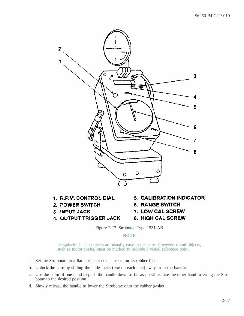
NOTE
Irregularly shaped objects are usually easy to measure. However, round objects,such as motor shafts, must be marked to provide a visual reference point.
a. Set the Strobotac on a flat surface so that it rests on its rubber feet.
b. Unlock the case by sliding the slide locks (one on each side) away from the handle.
c. Use the palm of one hand to push the handle down as far as possible. Use the other hand to swing the Stro-botac to the desired position.
d. Slowly release the handle to lower the Strobotac onto the rubber gasket.
Figure 2-17 Strobotac Type 1531-AB
S6260-BJ-GTP-010
2-37

Table 2-10 Strobotac ControlsFIGURE 2-17
REF. NO. CONTROL TYPE FUNCTION
1 R.P.M. Control dial Flashing rate.2 POWER Switch Power on-off.3 INPUT Jack External synchronization.4 OUTPUT Trigger jack Trigger pulse output.5 CALIBRATION Indicator light Indicates correct setting of calibration adjustments.6 RANGE Switch Selects r/m range.7 LOW CAL Screw Adjusts the ON-OFF pattern of the neon light.8 HIGH CAL Screw Adjusts the ON-OFF pattern of the neon light.
CAUTION
Ensure that the power matches the data on the plate next to the power cordon the panel before plugging the power cord into the receptacle.
e. Ensure that the power cord has a ground terminal. Ground the chassis if it does not.
f. Plug the Strobotac into the power supply.
g. Raise the reflector lamp to an upright position.
h. Position the Strobotac. The light beam can be pointed in almost any direction by the swivel arm and therotating reflector.
i. To calibrate the Strobotac:
(1) Allow the Strobotac to warm up for 10 minutes.
(2) Refer to the calibration chart in the cover for the HIGH CAL and LOW CAL R.P.M. dial settings indi-cated for the power line frequency being used.
(3) Turn the RANGE switch to the range required to make these settings.
(4) Set the R.P.M. dial to the exact HIGH CAL R.P.M. dial setting indicated by the calibration chart.
(5) Adjust the HIGH CAL screw until the ON/OFF pattern of the neon CALIBRATION indicator light stopsor nearly stops. The light does not have to be completely off.
(6) Set the R.P.M. dial at the exact LOW CAL R.P.M. dial settings indicated on the calibration chart.
(7) Adjust the LOW CAL screw until the ON/OFF pattern of the neon light stops or nearly stops. The lightdoes not have to be completely off.
(8) Return the R.P.M. dial to the HIGH CAL R.P.M. setting. Repeat the above steps if the neon light blinkson and off too quickly.
(9) The R.P.M. dial is now calibrated to within 1 percent on all scales.
j. Select the range on the RANGE selector switch. The speed limits for each range are marked near the appro-priate window.
NOTE
The motor may run at a slightly lower speed than nameplate data indicates. Tocompensate, set the R.P.M. dial at a flashing rate that is higher than the speed ofthe motor.
S6260-BJ-GTP-010
2-38

k. Slowly reduce the flashing rate until the first single image is observed. At this point, the flashing rate of theStrobotac will be equal to the speed of the motor. The speed can then be read directly from the R.P.M. dial.
l. Switch to the next higher range when using low or midspeed ranges. Do not move the R.P.M. dial setting.Check to see if the Strobotac is flashing at the fundamental speed of the object being measured. Because theratio between ranges is six to one, six images will appear at the next higher range if the Strobotac has beenset to the design speed.
m. Secure the Strobotac after use. Push the reflector down against the panel Keep the reflector cover up to pre-vent damage to the reflector.
n. Turn the RANGE switch to the 4,000 to 25,000 R.P.M. scale.
o. Wrap the power cord clockwise around the RANGE switch and the reflector.
p. Secure the power cord plug by sliding the ground terminal of the plug onto the pin holder.
q. Lift the Strobotac until it is free to pivot on the handle. Lower it into the case.
r. Slide both locks into place. Ensure that the locks are in place to keep the Strobotac case from falling open.
2-37. POLARIZATION INDEX TEST.
2-37.1 Polarization index (P1) is the ratio of the 10-minute insulation resistance value to the 1-minute insulationresistance value. The change in insulation resistance with the duration of the test potential application is usefulin appraising the cleanliness and dryness of a winding. Insulation resistance of a winding will normally increasewith the duration of the test voltage. The measured insulation resistance of a dry winding in good condition willreach a fairly steady value in 10 to 15 minutes. If the winding is wet or dirty, the steady value will usually bereached in 1 or 2 minutes. The slope of the curve is an indication of insulation condition. If the winding tem-perature has changed during the interval between the 1- and 10-minute measurements, the values of the insula-tion resistance used to determine the PI must be temperature-corrected. Temperature corrections should be madeto 25° C using the nomograph in figure 2-18.
S6260-BJ-GTP-010
2-39

2-37.2 The P1 test may be used as a diagnostic tool at any point in the reconditioning or rewind process to iden-tify the level of insulation contamination. The P1 test should be used during incoming inspection. Used in con-junction with the 1-minute insulation resistance test (paragraph 2-4 or paragraph 2-8), motors that have absorbedmoisture or other contaminants will be identified for reconditioning. Requirements applicable to the P1 test areas follows:
a. The PI test should be performed at incoming inspection if the temperature-corrected value of the 1-minuteinsulation resistance is greater than or equal to the ″Minimum for Operation″ and less than 5 times the appli-cable ″After Reconditioning″ value in table 3-2.
b. An exception to ″a″ is for motors with a sealed insulation system. If the value of 1-minute insulation resis-tance of a motor with sealed insulation is greater than or equal to the ″Minimum for Operation″ and less than500 megohm, a PI test should be performed.
Figure 2-18 Insulation Resistance-Temperature Nomograph
S6260-BJ-GTP-010
2-40

c. For most equipment, including induction motors, the minimum acceptable value of PI is 2.0. There are uniqueequipments that because of their construction cannot achieve values of PI as high as 2.0. Examples of suchequipment are some exciters and dc armatures. The repair activity is responsible for establishing minimumvalues of PI for these equipments that cannot attain a PI of 2.0.
d. If the polarization index is unacceptable, the equipment should be reconditioned.
2-38. LEXSECO CORE TESTER 1081D.
2-38.1 Core testing, as described in this paragraph, is mandatory for all motors when repairs are accomplishedat a depot level or contractor facility. For motors being repaired in a shipboard repair facility, core testing isoptional. If a core tester is readily available to the shipboard repair facility, core testing, as described in this para-graph, is recommended. Core testing is a valuable tool that will identify deteriorated stator and rotor cores withunacceptably high core losses. The core is a crucial element in completing the magnetic circuit. High core lossesseriously reduce the efficiency of the motor. If a core fails the core test, the feasibility of repair should be evalu-ated as described in NAVSEA S9086-KC-STM-010/CH 300. If the core is not repaired, either the core or theentire motor should be replaced. If immediate repair or replacement is not possible and the core is still viable,the core may be rewound for use on a temporary basis while a permanent replacement is obtained. The end usershould be advised of this condition since the motor will have a reduced life due to an increased operating tem-perature. A core test should be performed prior to burnout, stripping, and cleaning of the core. In this way, thetime and effort to strip and clean the core can be saved if the test shows an unacceptable core. By the same token,a core test should also be performed after stripping and cleaning to ensure that the core was not damaged dur-ing the process. A core test should be performed on motors which are to be reconditioned if core damage is sus-pected.
2-38.2 To perform a core test, proceed as follows:
a. A core tester such as a LEXSECO 1081 or equivalent shall be used.
b. If a core tester is not available, the following loop tests may be conducted to determine armature and statorcore acceptability. Keep records of all data collected.
c. Initial ac stator core test made prior to stripping and cleaning.
(1) Using the 1/64th scale on an engineer’s rule, measure the stator core length (CL), core depth (CD), corebore diameter (CID), and slot depth (SD).
(2) Effective stator core length is obtained as follows: CL = Measured core length x 0.80
(3) To determine the stator core depth, measure from the bottom of the coil slot to the core’s outer circum-ference.
(4) Effective core cross section area = (CL) x (CD).
(5) Estimated voltage per turn = 0.26 x core area.
(6) The number of cable turns to be placed through the stator core = supply voltage divided by the estimatedvolts per turn.
(7) Effective stator core diameter (ECD) = CID + (2SD) + CD.
(8) Ampere turns (AT) = 45 x ECD
(9) Current required = AT/Turns
(10) Select a cable size that has a current rating not less than that required to conduct the test as is calculatedin step (9) above.
S6260-BJ-GTP-010
2-41
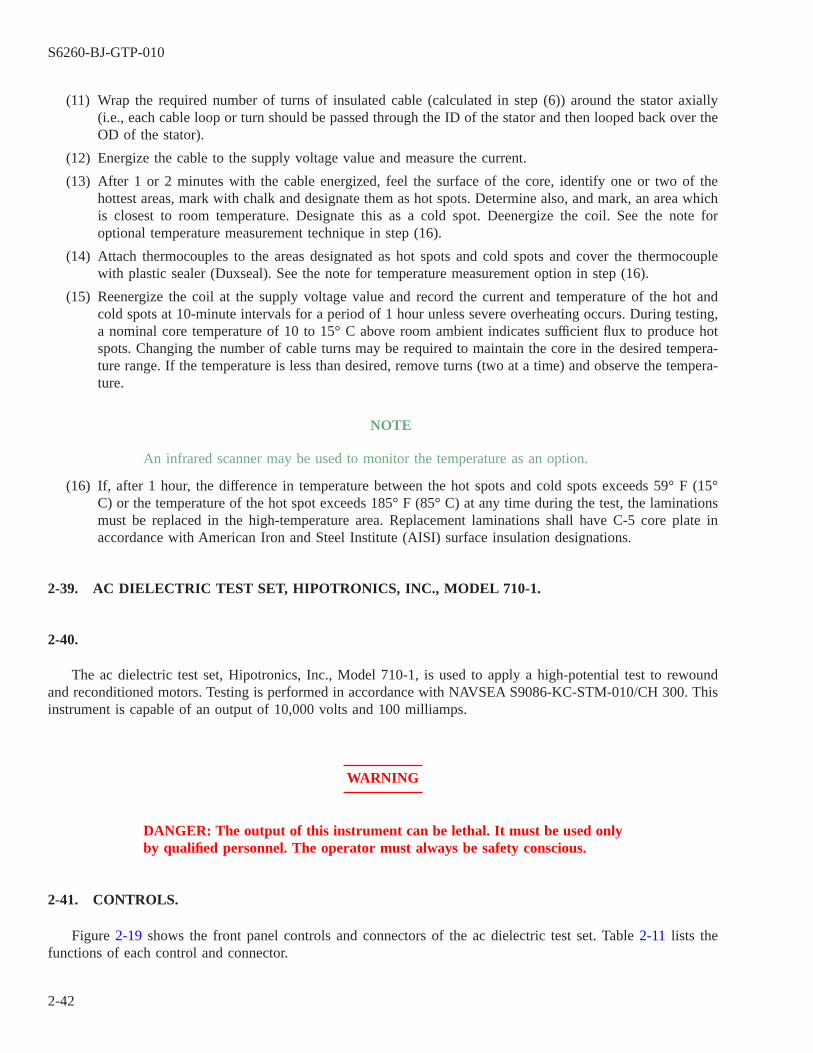
(11) Wrap the required number of turns of insulated cable (calculated in step (6)) around the stator axially(i.e., each cable loop or turn should be passed through the ID of the stator and then looped back over theOD of the stator).
(12) Energize the cable to the supply voltage value and measure the current.
(13) After 1 or 2 minutes with the cable energized, feel the surface of the core, identify one or two of thehottest areas, mark with chalk and designate them as hot spots. Determine also, and mark, an area whichis closest to room temperature. Designate this as a cold spot. Deenergize the coil. See the note foroptional temperature measurement technique in step (16).
(14) Attach thermocouples to the areas designated as hot spots and cold spots and cover the thermocouplewith plastic sealer (Duxseal). See the note for temperature measurement option in step (16).
(15) Reenergize the coil at the supply voltage value and record the current and temperature of the hot andcold spots at 10-minute intervals for a period of 1 hour unless severe overheating occurs. During testing,a nominal core temperature of 10 to 15° C above room ambient indicates sufficient flux to produce hotspots. Changing the number of cable turns may be required to maintain the core in the desired tempera-ture range. If the temperature is less than desired, remove turns (two at a time) and observe the tempera-ture.
NOTE
An infrared scanner may be used to monitor the temperature as an option.
(16) If, after 1 hour, the difference in temperature between the hot spots and cold spots exceeds 59° F (15°C) or the temperature of the hot spot exceeds 185° F (85° C) at any time during the test, the laminationsmust be replaced in the high-temperature area. Replacement laminations shall have C-5 core plate inaccordance with American Iron and Steel Institute (AISI) surface insulation designations.
2-39. AC DIELECTRIC TEST SET, HIPOTRONICS, INC., MODEL 710-1.
2-40.
The ac dielectric test set, Hipotronics, Inc., Model 710-1, is used to apply a high-potential test to rewoundand reconditioned motors. Testing is performed in accordance with NAVSEA S9086-KC-STM-010/CH 300. Thisinstrument is capable of an output of 10,000 volts and 100 milliamps.
WARNING
DANGER: The output of this instrument can be lethal. It must be used onlyby qualified personnel. The operator must always be safety conscious.
2-41. CONTROLS.
Figure 2-19 shows the front panel controls and connectors of the ac dielectric test set. Table 2-11 lists thefunctions of each control and connector.
S6260-BJ-GTP-010
2-42
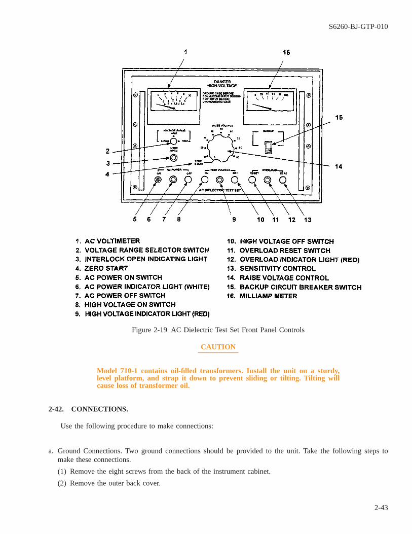
CAUTION
Model 710-1 contains oil-filled transformers. Install the unit on a sturdy,level platform, and strap it down to prevent sliding or tilting. Tilting willcause loss of transformer oil.
2-42. CONNECTIONS.
Use the following procedure to make connections:
a. Ground Connections. Two ground connections should be provided to the unit. Take the following steps tomake these connections.
(1) Remove the eight screws from the back of the instrument cabinet.
(2) Remove the outer back cover.
Figure 2-19 AC Dielectric Test Set Front Panel Controls
S6260-BJ-GTP-010
2-43

Table 2-11 AC Dielectric Test Set Controls and Connectors
FIGURE 2-19REF.NO. NAME TYPE FUNCTION
1 AC VOLTMETER Meter Three-range. Connected across output of instru-ment. Allows continuous monitoring of voltage.
2 VOLTAGE RANGE Selector switch Selects maximum output necessary for test.3 INTER OPEN Indicator light (amber) Indicates position of interlock switch when switch
is installed.4 ZERO START Rheostat position Zero-interlocked. Allows continuous adjustment to
variable transformer to raise voltage transformer toincrease voltage from 0 to maximum. Must bezeroed to start each test.
5 AC POWER ON Switch Turns power on and off.6 AC POWER Indicator light (white) Indicates power on and off.7 INTERLOCK
MOUNTEDEXTERNALLY
Pushbutton When locked in depressed position test cannot beperformed.
8 HIGH VOLTAGEON
Pushbutton Normally open. Energizes relay to apply power toprimary of high-voltage (NV) transformer.
9 HIGH VOLTAGE Indicator light (red) Indicates output of HV transformer. Is energizedand connected to test leads.
10 HIGH VOLTAGEOFF
Pushbutton Normally closed. Deenergizes the NV transformer.
11 OVERLOADRESET
Pushbutton Resets overload after overload trips.
12 OVERLOAD Indicator light (red) Indicates overload tripped. Do not run test when lit.Light will go out when OVERLOAD RESET ispushed.
13 SENS Control (rheostat knob) Adjust sensitivity of the trip overload element fromminimum to maximum. Should be set at minimumor full clockwise (CW) for test.
14 RAISE VOLTAGE Control Interlocked. Allows continuous adjustment of thevariable transformer to raise voltage from zero tomaximum. Must be at zero to start each test.
15 BACKUP Circuit breaker switch Provides backup tripping capability if overload failsto trip.
16 MILLIAMP Meter Indicates leakage current between high-voltage lineand ground.
NOTE
Note the two studs welded to the cabinet. One is adjacent to the gray power sup-ply cable. The other is adjacent to the black high-voltage cable.
b. Instrument Ground Strap Connection. To connect the instrument ground strap:
(1) Connect the ground strap to the stud adjacent to the gray instrument power supply cable.
(2) Pass the ground strap through the grommet in the instrument back cover that is occupied by the powercable.
(3) Connect the ground strap securely to the ship’s hull.
c. Test Ground Strap. To connect the test ground strap:
(1) Measure a length of ground strap the same length as the black high-voltage cable.
S6260-BJ-GTP-010
2-44
(2) Connect one end of this ground strap to the stud adjacent to the high-voltage line.
(3) Pass the other end of the strap through the grommet occupied by the high-voltage line.
(4) Fit the bitter end of the ground strap with a 25A alligator clamp.
(5) Bend the high-voltage line and its ground strap together, starting 2 feet above the alligator clamps. Tiethem together with nylon ties.
(6) Replace the back panel of the instrument.
(7) Replace the eight screws in the cover.
(8) Mount the unit in its permanent position.
2-43. INTERLOCK SWITCH.
The Hipotronics Model 710-1 uses extremely high voltage. The instrument must not be used without propersupervision. An interlock switch may be mounted externally to prevent unauthorized use of the equipment. Usethe following procedure to modify the instrument so that an interlock switch may be mounted:
a. Mount a single gang switch box adjacent to the instrument.
b. Remove the back of the instrument.
c. Locate terminals 4 and 5 in the instrument.
d. Remove the jumper from terminals 4 and 5.
e. Connect a length of DSGA-4 cable to terminals 4 and 5.
f. Bring the cable out of the instrument through the gray power cable grommet.
g. Replace the back of the instrument.
h. Lead the DSGA-4 cable from the instrument to the switchbox.
i. Connect the DSGA-4 to the single pole toggle switch, and mount the switch in the switch box.
j. Mount a locking attachment for switches (Hubbell Catalog No. 96062 or its equivalent) over the switch.
2-44. OPERATION.
Use the following procedure to conduct a high-potential test on a rewound or reconditioned winding:
WARNING
Never conduct a high-potential test on a winding that has failed a groundinsulation test.
a. Conduct an insulation resistance test (paragraph 2-4 or paragraph 2-8) on the winding before using the high-potential tester. Use a megohm bridge or a megohmmeter. If the 1-minute insulation resistance measurementcorrected to 25° C is less than 2 x (1 + E/1,000) megohms where E is the machine’s rated voltage, the wind-ing is not suitable for application of the high-potential test.
b. Erect barricades to keep personnel from passing through the test area.
c. Plug the Hipotronics Model 710-1 into a 115V ac 60-Hz, single-phase outlet.
S6260-BJ-GTP-010
2-45
CAUTION
Ensure that the instrument ground is firmly connected to the ships hull.Connect the ground lead to the instrument and motor.
d. Twist together the line leads of the winding that is being tested.
CAUTION
Twist together the leads of the winding not being tested when testing a two-speed, two-layer winding. Ground the winding not under test.
e. Connect the black high-voltage lead to the winding under test.
f. Connect the alligator clip of a shorting stick to the alligator clip of the ground or to the frame of the motor.
g. Connect the test ground strap to the frame of the winding.
h. Calculate the test voltage for the winding using the design voltage.
New windings: 2E + 1,000 = test voltage where E = design voltage of the winding.
Reconditioned windings: 2/3 (2E + 1,000) = test voltage .
i. Select the voltage scale for the test. Use the VOLTAGE RANGE selector to obtain midscale range.
j. Turn the RAISE VOLTAGE control fully counterclockwise (CCW) to zero.
k. Turn the SENS control fully CW to the MIN position.
l. Press the RESET.
NOTE
If there is an interlock switch, it must be on. The amber light will be out.
m. Place the backup circuit breaker in the ON position.
NOTE
The white indicator light should light.
n. Turn the AC POWER switch to ON.
NOTE
The red light in the HIGH VOLTAGE section should light.
o. Press the HIGH VOLTAGE switch ON.
p. Turn the RAISE VOLTAGE control CW to raise the voltage until the calculated test voltage can be read onthe ac kilovoltmeter.
q. Apply the test voltage for 1 minute.
r. Reduce the voltage after 1 minute at a rate which will bring the voltage to one-fourth of the test voltage in15 seconds. Turn the RAISE VOLTAGE control CCW to reduce the voltage.
S6260-BJ-GTP-010
2-46
s. Reduce the voltage to zero by turning the RAISE VOLTAGE control CCW and pressing the HIGH VOLT-AGE OFF switch.
NOTE
Failure of the winding under test is indicated by the red OVERLOAD light com-ing on, by the voltage dropping to zero, and by an increasing current reading onthe ac milliammeter.
t. To run another test, return the RAISE VOLTAGE control to zero, push the OVERLOAD RESET, ensure theBACKUP is in the ON position, and push the HIGH VOLTAGE ON switch.
u. Repeat steps p through t.
v. Short the high-voltage lead to the ground strap using the shorting stick.
w. Turn the AC POWER switch off.
x. Disconnect the high-voltage lead and ground strap from the test winding.
y. Make the leads up and stow them on the high-potential tester.
z. Conduct a ground insulation test on the test winding. The ground reading must be in accordance withNAVSEA S9086-KC-STM-010/CH 300.
2-45. AC AND DC DIELECTRIC TEST SET, HIPOTRONICS, INC., MODEL 115-A.
2-46.
The Hipotronics Inc., Model 115-A dielectric test set is used to apply an ac or dc high-potential test to new,rewound, or reconditioned motors. Testing is performed in accordance with NAVSEA 9086-KC-STM-010/CH300. This instrument is capable of an output of 12,000 volts ac at 0 to 5 milliamps (mA) and 15,000 volts dc at0 to 50 microamps (µA).
WARNING
DANGER: The output of this instrument can be lethal. It must be used onlyby qualified personnel.
2-47. CONTROLS.
Figure 2-20 shows the front panel and controls of the dielectric test set Model 115-A. Table 2-12 lists thefunctions of each control and connector.
WARNING
Both ac and dc jacks are energized when the voltage range selector switch isset to HIGH. To ensure operator safety, an external interlock switch must be
S6260-BJ-GTP-010
2-47
Warning - precedesused at all times. Follow the procedure in paragraph 2-43 to modify theinstrument so that an interlock switch may be mounted.
2-48. SETUP.
a. To ensure accurate meter readings, place the instrument on a solid surface so that the meters are at eye level.
b. Secure all external interlock switches and ensure that the AC POWER ON switch is off.
c. Ensure that the case is grounded before connecting input power. A ground post on the front panel may be usedfor this purpose.
d. Plug the cord into a 115-volt, 50/60 Hz grounded (three-prong) outlet.
e. Turn the AC POWER switch to ON.
WARNING
NEVER conduct a high-potential test on a winding that has failed a groundinsulation test.
2-49. OPERATION.
2-50. DC HIPOT TESTING.
NOTE
To ensure that only leakage current from the test sample is recorded on the cur-rent meter, remove any other potential sources of leakage in or near the testsample before beginning the test.
a. Set the OUTPUT & CURRENT range selector to the appropriate dc current range.
b. Ensure that the unit is properly grounded and that the RAISE VOLTAGE control is at zero.
S6260-BJ-GTP-010
2-48
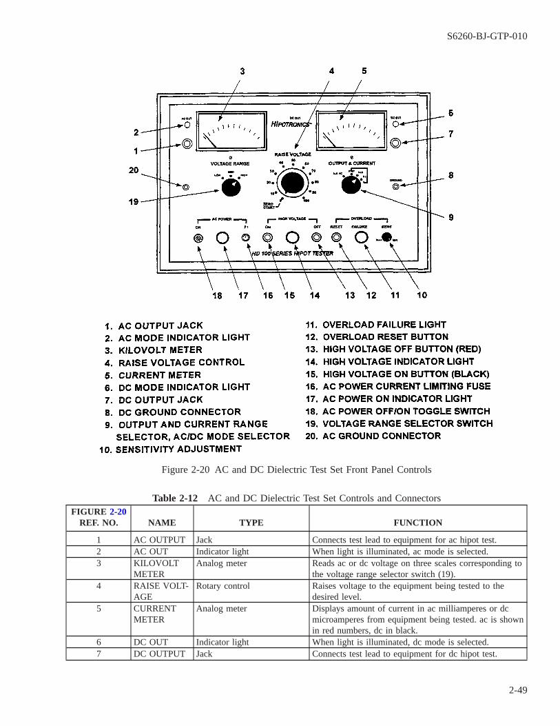
Table 2-12 AC and DC Dielectric Test Set Controls and ConnectorsFIGURE 2-20
REF. NO. NAME TYPE FUNCTION
1 AC OUTPUT Jack Connects test lead to equipment for ac hipot test.2 AC OUT Indicator light When light is illuminated, ac mode is selected.3 KILOVOLT
METERAnalog meter Reads ac or dc voltage on three scales corresponding to
the voltage range selector switch (19).4 RAISE VOLT-
AGERotary control Raises voltage to the equipment being tested to the
desired level.5 CURRENT
METERAnalog meter Displays amount of current in ac milliamperes or dc
microamperes from equipment being tested. ac is shownin red numbers, dc in black.
6 DC OUT Indicator light When light is illuminated, dc mode is selected.7 DC OUTPUT Jack Connects test lead to equipment for dc hipot test.
Figure 2-20 AC and DC Dielectric Test Set Front Panel Controls
S6260-BJ-GTP-010
2-49

Table 2-12 AC and DC Dielectric Test Set Controls and Connectors -
Continued
FIGURE 2-20REF. NO. NAME TYPE FUNCTION
8 DC GROUND Jack Connects the equipment being tested to ground andcompletes the high-voltage circuit through the currentmeter.
9 OUTPUT &CURRENT
Four-position selector switch Selects between the one ac and three dc current rangesand determines the mode (ac or dc). ac is on red scale,dc on black.
10 SENS Two-position rotary control Sets overload control.11 OVERLOAD
FAILUREIndicator light Illuminates to indicate leakage current has exceeded
SENS setting.12 RESET Pushbutton Resets the overload after failure, turns off FAILURE
light, and permits further testing.13 OFF Pushbutton When pressed, deenergizes the high-voltage section.14 LIGHT Indicator light Illuminates when high-voltage section is energized.15 ON Pushbutton Press to activate high-voltage section.16 F1 Fuse, AC Power Current
LimitingProtects the tester. Access for replacement by pressingand turning the cap counterclockwise.
17 LIGHT Indicator light, AC Power Illuminates when tester is connected and turned on.18 ON Toggle switch Turns tester off and on.19 VOLTAGE
RANGEThree-position selectorswitch
Selects which scale will be used on the voltmeter.
20 GROUND Jack Connects the ac equipment being tested to ground andcompletes the high-voltage circuit through the currentmeter.
c. Connect the low end of the test sample to a ground post. The ground lead supplied with the unit may be usedfor this purpose.
d. Connect the alligator clip of the shielded high-voltage test lead to the high end of the test sample.
e. Set OVERLOAD to desired sensitivity. Refer to paragraph 2-52 for overload adjustment.
f. Press the HIGH VOLTAGE ON pushbutton.
NOTE
If the test sample breaks down, the overload trips and causes the FAILURE indi-cator to light. Press the RESET button to reset the system. After the RAISEVOLTAGE control reaches zero, connect a ground to the high voltage lead toprevent shock. To resume testing: ensure that the voltmeter is at zero, disconnectthe leads from the test sample, and go to step 2-50.c.
g. Increase output voltage to the desired level by turning the RAISE VOLTAGE control.
h. Maintain output voltage at the desired level for the required amount of test time. Note the reading on the cur-rent meter.
i. When the test is complete, turn the RAISE VOLTAGE control to zero.
j. Wait for the voltmeter reading to return to zero, then press the HIGH VOLTAGE OFF pushbutton.
S6260-BJ-GTP-010
2-50
WARNING
DANGER: The output of this instrument can be lethal. It must be used onlyby qualified personnel. The operator must always be safely conscious.
WARNING
Both ac and dc jacks are energized when high voltage is activated.
2-51. AC HIPOT TESTING.
a. Set the OUTPUT & CURRENT range selector to the ac position.
b. Ensure that the unit is properly grounded and that the RAISE VOLTAGE control is at zero.
c. Connect the low end of the test sample to a ground post. The ground lead supplied with the unit may be usedfor this purpose.
d. Connect the alligator clip of the shielded high-voltage test lead to the high end of the test sample.
e. Set OVERLOAD to the desired sensitivity. Refer to paragraph 2-52 for overload adjustment.
f. Press the HIGH VOLTAGE ON pushbutton.
NOTE
If the test sample breaks down, the overload trips and causes the FAILURE indi-cator to light. Press the RESET button to reset the system. After the RAISEVOLTAGE control reaches zero, connect a ground to the high voltage lead toprevent shock. To resume testing: ensure that the voltmeter is at zero, disconnectthe leads from the test sample, and go to step 2-51.c.
g. Increase the output voltage to the desired level by turning the RAISE VOLTAGE control.
h. Maintain output voltage at the desired level for the required amount of test time. Note the reading on the cur-rent meter.
i. When the test is complete, turn the RAISE VOLTAGE control to zero.
2-52. OVERLOAD ADJUSTMENT.
2-52.1 Adjusting the overload point (the amount of leakage current that causes the failure signal to be activated)is important for accurate hipot testing. The HD100 Series hipot testers will test for leakage current at any desiredpoint between 500 µA (maximum sensitivity) and 5.5 mA (minimum sensitivity), depending on the SENS con-trol seating. If AC testing is being performed, do not set the SENS control to the MAX setting, because leakagecurrent in most test samples will exceed 50 µA and repeatedly activate the failure signal.
2-52.2 Adjusting the Overload.
S6260-BJ-GTP-010
2-51
a. Ensure that the unit is properly grounded and that the RAISE VOLTAGE control is at zero.
b. Set the OUTPUT & CURRENT range selector to the appropriate range setting.
c. Connect the low end of the test sample to a ground post. The ground lead supplied with the unit may be usedfor this purpose.
d. Connect the alligator clip of the shielded HV test lead to the high end of the test sample.
e. Press the HIGH VOLTAGE ON pushbutton.
f. Increase the output voltage by turning the RAISE VOLTAGE control until the desired level of trip current isindicated on the current meter.
g. Turn the SENS control slowly toward MAX until the overload trips and shuts off the high voltage. The FAIL-URE indicator lights.
h. Turn the RAISE VOLTAGE control to zero. Press the RESET button.
i. Verify the accuracy of the OVERLOAD setting by repeating step 2-52.2.g. Note the reading on the currentmeter when the FAILURE indicator lights.
j. If the current meter reading matches the value of the desired trip current leakage, turn the RAISE VOLTAGEcontrol to zero and press the RESET pushbutton. If the current meter reading does not match the value of thedesired trip current leakage, turn the RAISE VOLTAGE control to zero, press the RESET pushbutton, andbegin again at step 2-52.2.f.
k. Ground the high voltage output lead and disconnect the resistive load.
l. Resume dc or ac hipot testing at step c of paragraph 2-50 (dc hipot testing) or paragraph 2-51 (ac hipot test-ing).
2-53. TYPICAL DIAL INDICATOR.
2-54.
Dial indicators are used by electricians to measure shaft and bearing runout, as well as coupling alignment.They can be mounted on test stands or mounted directly with clamps or a magnetic base on the equipment to betested. Figure 2-21 shows a typical dial indicator.
S6260-BJ-GTP-010
2-52
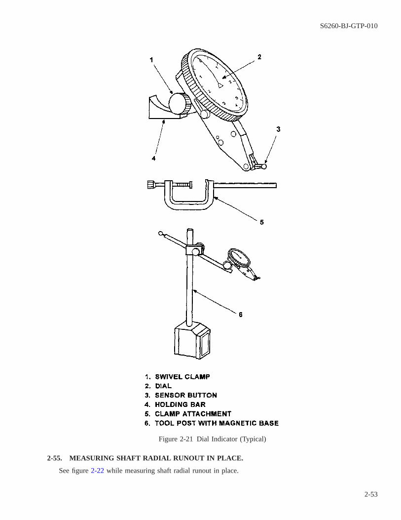
2-55. MEASURING SHAFT RADIAL RUNOUT IN PLACE.
See figure 2-22 while measuring shaft radial runout in place.
Figure 2-21 Dial Indicator (Typical)
S6260-BJ-GTP-010
2-53

a. Attach the magnetic base on the motor end bell, deck, or other suitable stationary surface.
b. Mount the dial indicator on the tool post holder.
c. Adjust the tool post holder to permit easy reading of the instrument face.
NOTE
Shaft must be clean and free of corrosion at the dial indicator contact point.
d. Bring the sensor button into contact with the surface to be measured. Tilt the adjustable sensing arm to wipeacross the surface being measured. The button should contact the shaft as close to the end as possible.
e. Raise and lower the sensor button with the tool post thumbscrew to determine the full travel of the indicator.
f. With the pointer at midtravel, zero the bezel.
g. Slowly rotate the shaft. The instrument pointer should remain at zero if the shaft is straight.
NOTE
Runout should not exceed 0.002 inch total indicator reading, unless otherwisespecified on equipment drawings.
If the bearings have failed, this test must be conducted with the rotor in V blocksafter disassembly and bearing removal.
Figure 2-22 Shaft Runout Indication
S6260-BJ-GTP-010
2-54

h. Record the measurement on the motor data sheet (mechanical) (figure 2-23).
2-56. MEASURING FACE RUNOUT OF BEARING, INNER RING.
Use the following procedure to measure face runout of bearing inner ring (figure 2-24).
a. Remove the outer bearing cap, if applicable.
b. Mount a magnetic tool holder on the end bell of the motor.
c. Mount the dial indicator on the tool post holder.
d. Bring the sensor button into contact with the bearing inner ring.
e. Raise and lower the sensor button to determine the full travel of the indicator pointer.
f. Leave the pointer at midtravel. Zero the bezel.
g. Rotate the shaft with the sensor button against the bearing inner ring.
NOTE
The maximum allowable face runout should be within 0.001 inch per inch diam-eter for general bearing applications and 0.0003 inch per inch diameter (maxi-mum) for quiet (NT-4) bearings.
h. Record the measurement on the motor data sheet (mechanical) (figure 2-23).
CAUTION
Take care not to damage the dial indicator. Installed motors may not haveclearance for full 360-degree rotation.
2-57. MEASURING FACE RUNOUT OF BEARING OUTER RING.
To measure face runout of bearing outer ring:
a. Use a C-clamp tool post holder to attach the dial indicator to the motor shaft.
b. Attach the dial indicator to the tool post holder.
c. Bring the sensor button into contact with bearing outer race face.
S6260-BJ-GTP-010
2-55
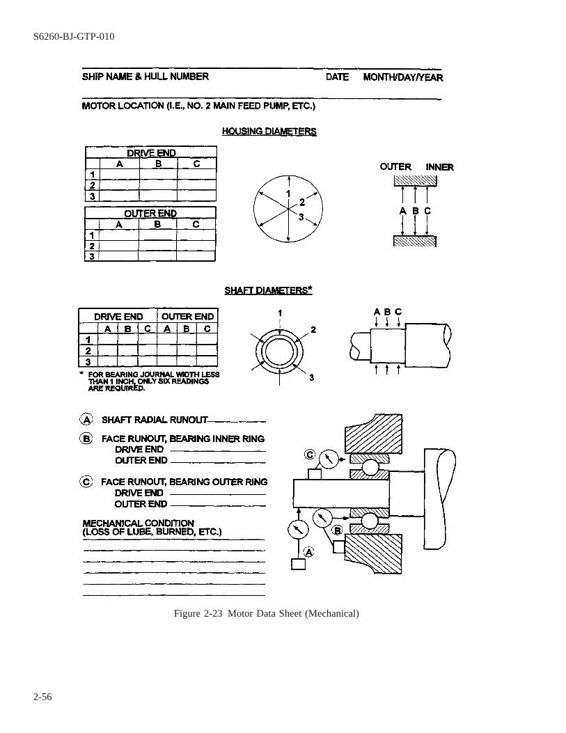
Figure 2-23 Motor Data Sheet (Mechanical)
S6260-BJ-GTP-010
2-56

d. Raise and lower the sensor button to determine the full travel of the indicator pointer.
e. Leave the pointer at mid-travel. Zero the bezel.
f. Rotate the shaft with dial indicator attached. Check the stiffness of the indicator setup at several positions.Since the gravity load may cause the indicator to shift its position, it is important that the indicator be heldrigidly.
NOTE
Runout should not exceed 0.002 inch total indicator reading, unless otherwisespecified on equipment drawings.
Figure 2-24 Measuring Bearing Inner Rings
S6260-BJ-GTP-010
2-57
If the bearings have failed, this test must be conducted with the rotor in V blocksafter disassembly and bearing removal.
g. Record the measurement on the motor data sheet (mechanical) (figure 2-23) and note the locations of themaximum and minimum readings.
2-58. TYPICAL BORE GAGE AND RING MASTER.
2-59.
The bore gage is a dial indicating instrument used to make precise measurements inside holes (i.e., bearinghousings). Because it is a dial indicating instrument, it can give direct readings. Determination of proper pressureagainst the walls of the bore does not depend on sense of touch as it does when using a micrometer. Great skillis not required to get consistently accurate results. Figure 2-25 shows a typical bore gage. Table 2-13 describesits components.
2-60. CALIBRATION.
The bore gage indicates deviation from a standard. It must, therefore, be calibrated (zeroed) using a standard.A device called a ring master (or ring standard) is used to zero the bore gage. The ring master is a precisiondevice, ground to the dimension stamped on it.
NOTE
The ring master must be carefully cared for to preserve its accuracy. Do not dropor scratch it. Wipe it clean of all dust, dirt, or grease before use and coat it with2190 TEP, mineral oil, or a similar product after use to prevent corrosion.
2-61. PROCEDURE FOR USE OF A BORE GAGE.
Use the following procedure to measure a bearing housing with a bore gage:
NOTE
Allow at least 1 hour for temperature stabilization of the bore gage, standard, andhousing prior to taking measurements.
a. Remove the bearing housing and clean it thoroughly.
S6260-BJ-GTP-010
2-58

b. Determine the bearing size from the numbers on the bearing or from the technical manual. Consult table 2-14to obtain the maximum and minimum dimensions of the housing for that size bearing. Record them on themotor data sheet (mechanical) (figure 2-23). For example:
Figure 2-25 Typical Bore Gage
S6260-BJ-GTP-010
2-59
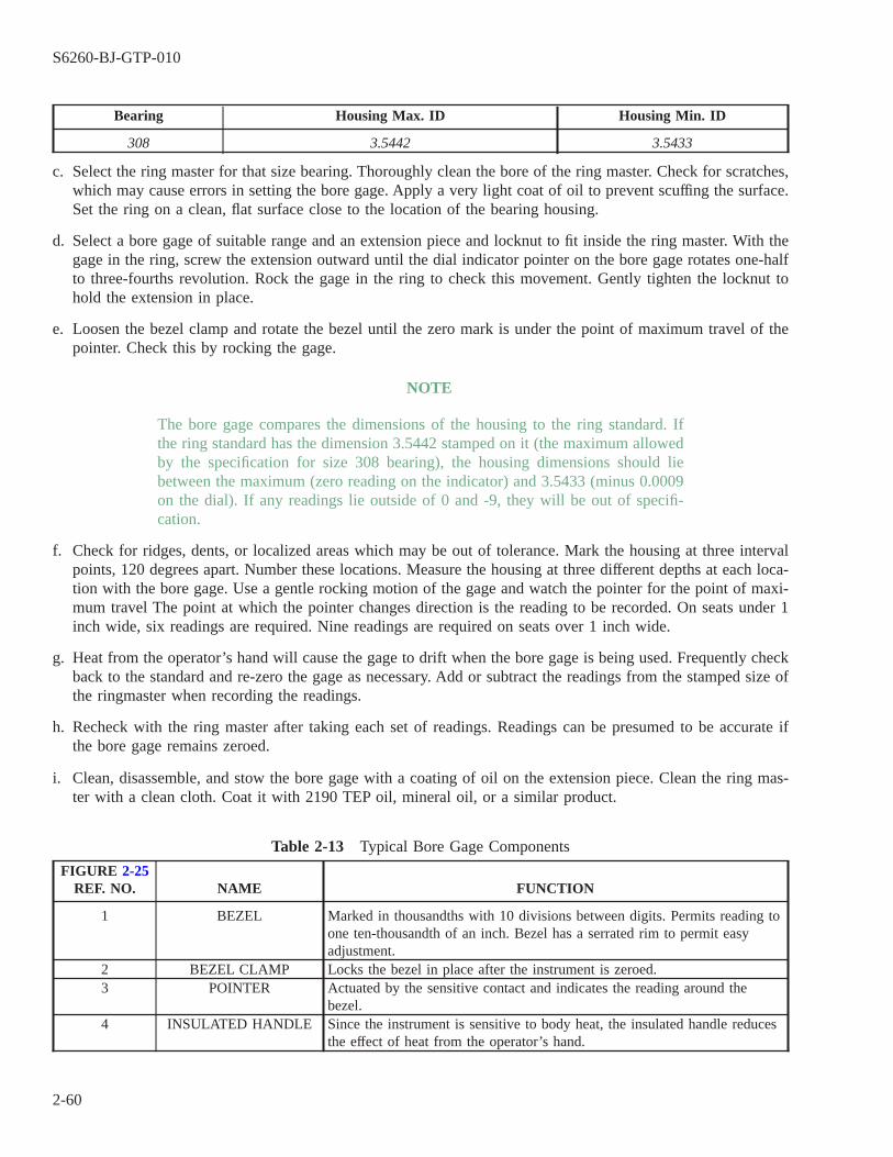
Bearing Housing Max. ID Housing Min. ID
308 3.5442 3.5433
c. Select the ring master for that size bearing. Thoroughly clean the bore of the ring master. Check for scratches,which may cause errors in setting the bore gage. Apply a very light coat of oil to prevent scuffing the surface.Set the ring on a clean, flat surface close to the location of the bearing housing.
d. Select a bore gage of suitable range and an extension piece and locknut to fit inside the ring master. With thegage in the ring, screw the extension outward until the dial indicator pointer on the bore gage rotates one-halfto three-fourths revolution. Rock the gage in the ring to check this movement. Gently tighten the locknut tohold the extension in place.
e. Loosen the bezel clamp and rotate the bezel until the zero mark is under the point of maximum travel of thepointer. Check this by rocking the gage.
NOTE
The bore gage compares the dimensions of the housing to the ring standard. Ifthe ring standard has the dimension 3.5442 stamped on it (the maximum allowedby the specification for size 308 bearing), the housing dimensions should liebetween the maximum (zero reading on the indicator) and 3.5433 (minus 0.0009on the dial). If any readings lie outside of 0 and -9, they will be out of specifi-cation.
f. Check for ridges, dents, or localized areas which may be out of tolerance. Mark the housing at three intervalpoints, 120 degrees apart. Number these locations. Measure the housing at three different depths at each loca-tion with the bore gage. Use a gentle rocking motion of the gage and watch the pointer for the point of maxi-mum travel The point at which the pointer changes direction is the reading to be recorded. On seats under 1inch wide, six readings are required. Nine readings are required on seats over 1 inch wide.
g. Heat from the operator’s hand will cause the gage to drift when the bore gage is being used. Frequently checkback to the standard and re-zero the gage as necessary. Add or subtract the readings from the stamped size ofthe ringmaster when recording the readings.
h. Recheck with the ring master after taking each set of readings. Readings can be presumed to be accurate ifthe bore gage remains zeroed.
i. Clean, disassemble, and stow the bore gage with a coating of oil on the extension piece. Clean the ring mas-ter with a clean cloth. Coat it with 2190 TEP oil, mineral oil, or a similar product.
Table 2-13 Typical Bore Gage Components
FIGURE 2-25REF. NO. NAME FUNCTION
1 BEZEL Marked in thousandths with 10 divisions between digits. Permits reading toone ten-thousandth of an inch. Bezel has a serrated rim to permit easyadjustment.
2 BEZEL CLAMP Locks the bezel in place after the instrument is zeroed.3 POINTER Actuated by the sensitive contact and indicates the reading around the
bezel.4 INSULATED HANDLE Since the instrument is sensitive to body heat, the insulated handle reduces
the effect of heat from the operator’s hand.
S6260-BJ-GTP-010
2-60
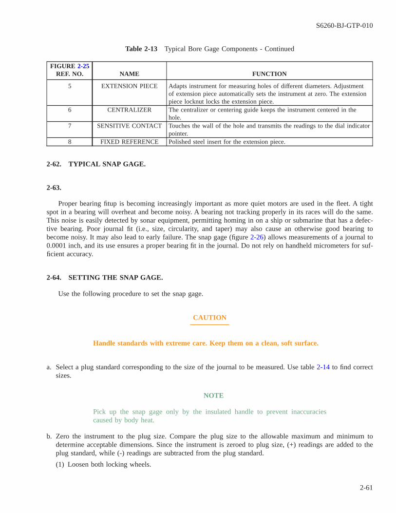
Table 2-13 Typical Bore Gage Components - Continued
FIGURE 2-25REF. NO. NAME FUNCTION
5 EXTENSION PIECE Adapts instrument for measuring holes of different diameters. Adjustmentof extension piece automatically sets the instrument at zero. The extensionpiece locknut locks the extension piece.
6 CENTRALIZER The centralizer or centering guide keeps the instrument centered in thehole.
7 SENSITIVE CONTACT Touches the wall of the hole and transmits the readings to the dial indicatorpointer.
8 FIXED REFERENCE Polished steel insert for the extension piece.
2-62. TYPICAL SNAP GAGE.
2-63.
Proper bearing fitup is becoming increasingly important as more quiet motors are used in the fleet. A tightspot in a bearing will overheat and become noisy. A bearing not tracking properly in its races will do the same.This noise is easily detected by sonar equipment, permitting homing in on a ship or submarine that has a defec-tive bearing. Poor journal fit (i.e., size, circularity, and taper) may also cause an otherwise good bearing tobecome noisy. It may also lead to early failure. The snap gage (figure 2-26) allows measurements of a journal to0.0001 inch, and its use ensures a proper bearing fit in the journal. Do not rely on handheld micrometers for suf-ficient accuracy.
2-64. SETTING THE SNAP GAGE.
Use the following procedure to set the snap gage.
CAUTION
Handle standards with extreme care. Keep them on a clean, soft surface.
a. Select a plug standard corresponding to the size of the journal to be measured. Use table 2-14 to find correctsizes.
NOTE
Pick up the snap gage only by the insulated handle to prevent inaccuraciescaused by body heat.
b. Zero the instrument to the plug size. Compare the plug size to the allowable maximum and minimum todetermine acceptable dimensions. Since the instrument is zeroed to plug size, (+) readings are added to theplug standard, while (-) readings are subtracted from the plug standard.
(1) Loosen both locking wheels.
S6260-BJ-GTP-010
2-61
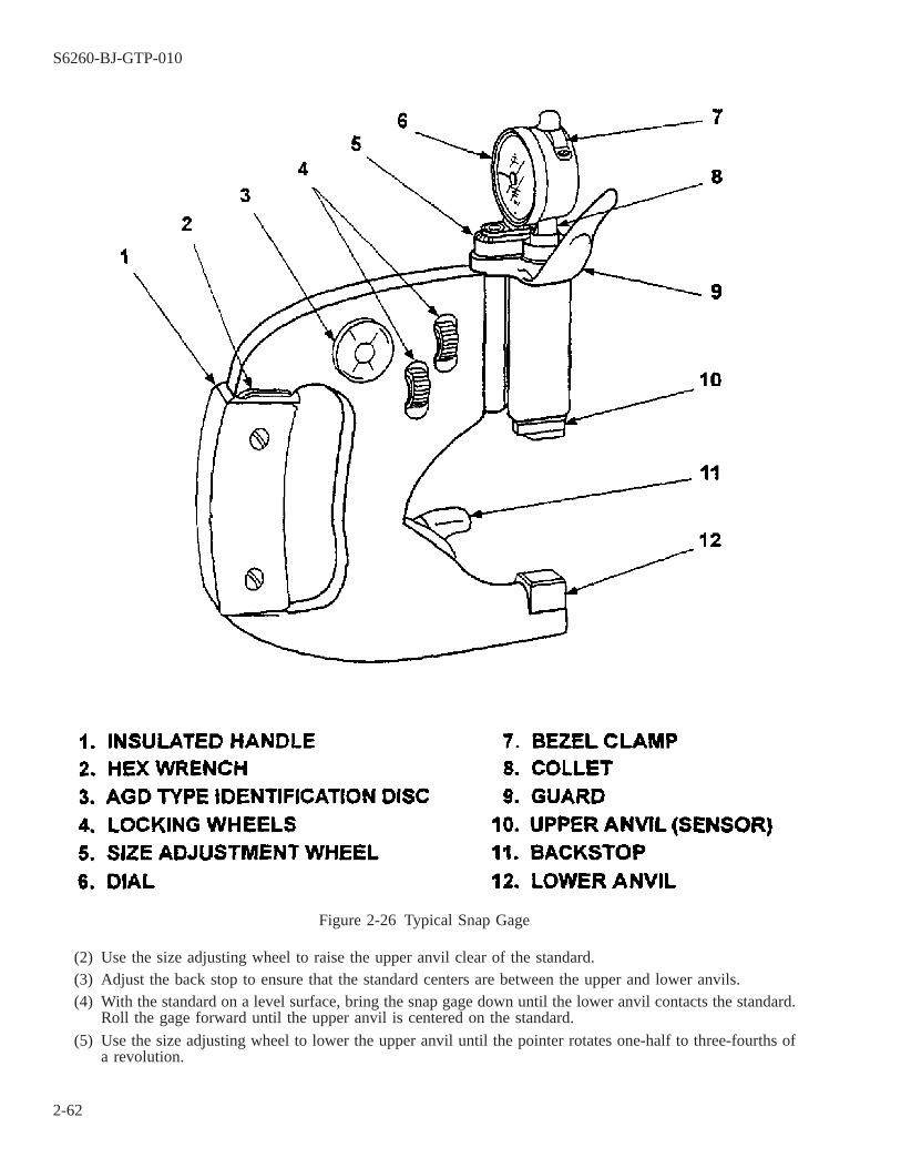
(2) Use the size adjusting wheel to raise the upper anvil clear of the standard.(3) Adjust the back stop to ensure that the standard centers are between the upper and lower anvils.(4) With the standard on a level surface, bring the snap gage down until the lower anvil contacts the standard.
Roll the gage forward until the upper anvil is centered on the standard.
(5) Use the size adjusting wheel to lower the upper anvil until the pointer rotates one-half to three-fourths ofa revolution.
Figure 2-26 Typical Snap Gage
S6260-BJ-GTP-010
2-62
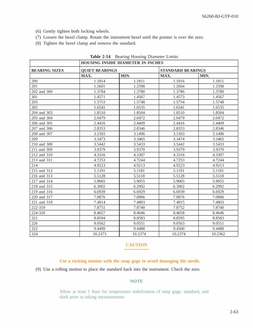
(6) Gently tighten both locking wheels.(7) Loosen the bezel clamp. Rotate the instrument bezel until the pointer is over the zero.(8) Tighten the bezel clamp and remove the standard.
Table 2-14 Bearing Housing Diameter LimitsHOUSING INSIDE DIAMETER IN INCHES
BEARING SIZES QUIET BEARINGS STANDARD BEARINGSMAX. MIN. MAX. MIN.
200 1.1814 1.1811 1.1816 1.1811201 1.2601 1.2598 1.2604 1.2598202 and 300 1.3784 1.3780 1.3786 1.3780301 1.4571 1.4567 1.4573 1.4567203 1.5753 1.5748 1.5754 1.5748302 1.6541 1.6535 1.6541 1.6535204 and 303 1.8510 1.8504 1.8510 1.8504205 and 304 2.0479 2.0472 2.0479 2.0472206 and 305 2.4416 2.4409 2.4416 2.4409207 and 306 2.8353 2.8346 2.8353 2.8346208 and 307 3.1503 3.1496 3.1503 3.1496209 3.3473 3.3465 3.3474 3.3465210 and 308 3.5442 3.5433 3.5442 3.5433211 and 309 3.9379 3.9370 3.9379 3.9370212 and 310 4.3316 4.3307 4.3316 4.3307213 and 311 4.7253 4.7244 4.7253 4.7244214 4.9223 4.9213 4.9223 4.9213215 and 312 5.1191 5.1181 5.1191 5.1181216 and 313 5.5128 5.5118 5.5128 5.5118217 and 314 5.9065 5.9055 5.9065 5.9055218 and 315 6.3002 6.2992 6.3002 6.2992219 and 316 6.6939 6.6929 6.6939 6.6929220 and 317 7.0876 7.0866 7.0876 7.0866221 and 318 7.4814 7.4803 7.4815 7.4803222-319 7.8751 7.8740 7.8752 7.8740224-320 8.4657 8.4646 8.4658 8.4646321 8.8594 8.8583 8.8595 8.8583226 9.0562 9.0551 9.0563 9.0551322 9.4499 9.4488 9.4500 9.4488324 10.2373 10.2374 10.2374 10.2362
CAUTION
Use a rocking motion with the snap gage to avoid damaging the anvils.
(9) Use a rolling motion to place the standard back into the instrument. Check the zero.
NOTE
Allow at least 1 hour for temperature stabilization of snap gage, standard, andshaft prior to taking measurements.
S6260-BJ-GTP-010
2-63
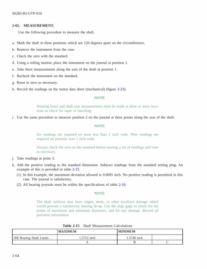
2-65. MEASUREMENT.
Use the following procedure to measure the shaft.
a. Mark the shaft in three positions which are 120 degrees apart on the circumference.
b. Remove the instrument from the case.
c. Check the zero with the standard.
d. Using a rolling motion, place the instrument on the journal at position 1.
e. Take three measurements along the axis of the shaft at position 1.
f. Recheck the instrument on the standard.
g. Reset to zero as necessary.
h. Record the readings on the motor data sheet (mechanical) (figure 2-23).
NOTE
Housing bores and shaft seat measurements must be made at three or more loca-tions to check for taper or barreling.
i. Use the same procedure to measure position 2 on the journal at three points along the axis of the shaft.
NOTE
Six readings are required on seats less than 1 inch wide. Nine readings arerequired on journals over 1 inch wide.
Always check the zero on the standard before starting a set of readings and resetas necessary.
j. Take readings at point 3.
k. Add the positive reading to the standard dimension. Subtract readings from the standard setting plug. Anexample of this is provided in table 2-15.
(1) In this example, the maximum deviation allowed is 0.0005 inch. No positive reading is permitted in thiscase. The journal is satisfactory.
(2) All bearing journals must be within the specifications of table 2-16.
NOTE
The shaft surfaces may have ridges, dents, or other localized damage whichwould prevent a satisfactory bearing fit-up. Use the snap gage to check for thepoints of maximum and minimum diameters, and for any damage. Record allpertinent information.
Table 2-15 Shaft Measurement Calculations
MAXIMUM MINIMUM
308 Bearing Shaft Limits 1.5753 inch 1.5748 inchA B C
S6260-BJ-GTP-010
2-64
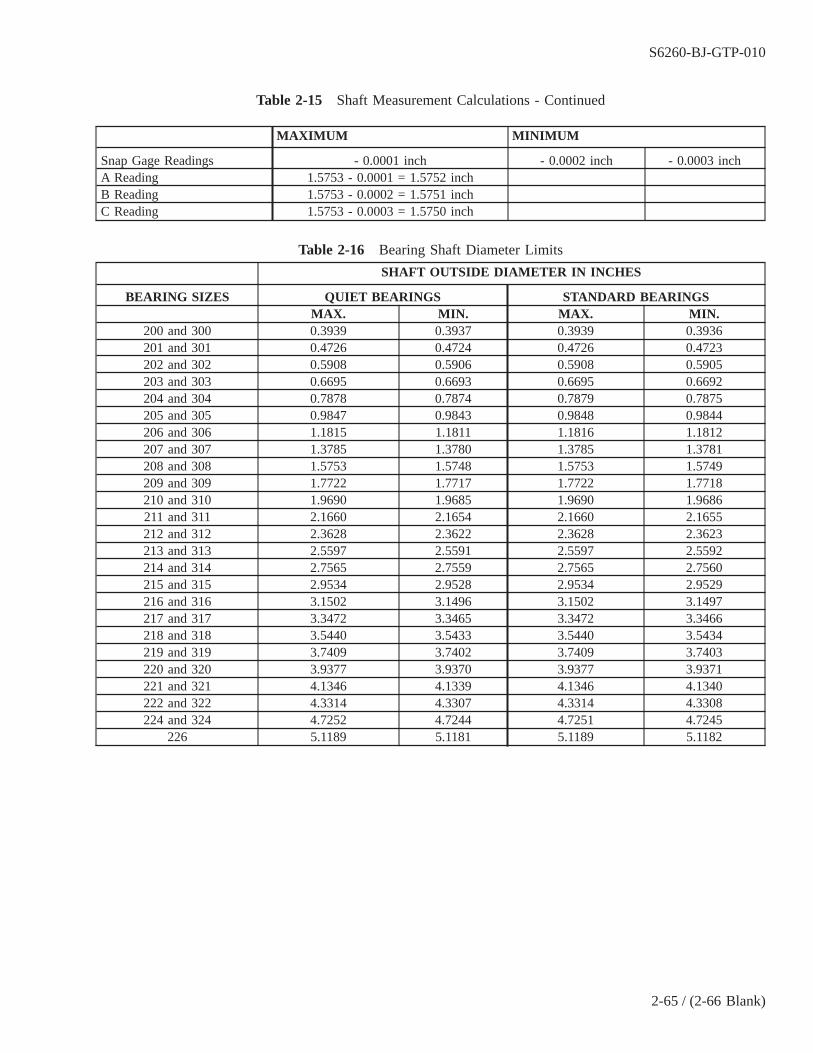
Table 2-15 Shaft Measurement Calculations - Continued
MAXIMUM MINIMUM
Snap Gage Readings - 0.0001 inch - 0.0002 inch - 0.0003 inchA Reading 1.5753 - 0.0001 = 1.5752 inchB Reading 1.5753 - 0.0002 = 1.5751 inchC Reading 1.5753 - 0.0003 = 1.5750 inch
Table 2-16 Bearing Shaft Diameter Limits
SHAFT OUTSIDE DIAMETER IN INCHES
BEARING SIZES QUIET BEARINGS STANDARD BEARINGSMAX. MIN. MAX. MIN.
200 and 300 0.3939 0.3937 0.3939 0.3936201 and 301 0.4726 0.4724 0.4726 0.4723202 and 302 0.5908 0.5906 0.5908 0.5905203 and 303 0.6695 0.6693 0.6695 0.6692204 and 304 0.7878 0.7874 0.7879 0.7875205 and 305 0.9847 0.9843 0.9848 0.9844206 and 306 1.1815 1.1811 1.1816 1.1812207 and 307 1.3785 1.3780 1.3785 1.3781208 and 308 1.5753 1.5748 1.5753 1.5749209 and 309 1.7722 1.7717 1.7722 1.7718210 and 310 1.9690 1.9685 1.9690 1.9686211 and 311 2.1660 2.1654 2.1660 2.1655212 and 312 2.3628 2.3622 2.3628 2.3623213 and 313 2.5597 2.5591 2.5597 2.5592214 and 314 2.7565 2.7559 2.7565 2.7560215 and 315 2.9534 2.9528 2.9534 2.9529216 and 316 3.1502 3.1496 3.1502 3.1497217 and 317 3.3472 3.3465 3.3472 3.3466218 and 318 3.5440 3.5433 3.5440 3.5434219 and 319 3.7409 3.7402 3.7409 3.7403220 and 320 3.9377 3.9370 3.9377 3.9371221 and 321 4.1346 4.1339 4.1346 4.1340222 and 322 4.3314 4.3307 4.3314 4.3308224 and 324 4.7252 4.7244 4.7251 4.7245
226 5.1189 5.1181 5.1189 5.1182
S6260-BJ-GTP-010
2-65 / (2-66 Blank)

2-66@@FIpgtype@@BLANK@@!FIpgtype@@
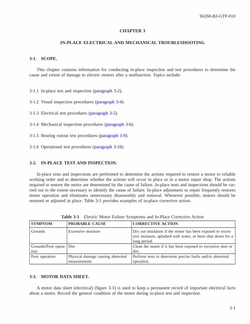
CHAPTER 3
IN-PLACE ELECTRICAL AND MECHANICAL TROUBLESHOOTING
3-1. SCOPE.
This chapter contains information for conducting in-place inspection and test procedures to determine thecause and extent of damage to electric motors after a malfunction. Topics include:
3-1.1 In-place test and inspection (paragraph 3-2).
3-1.2 Visual inspection procedures (paragraph 3-4).
3-1.3 Electrical test procedures (paragraph 3-5).
3-1.4 Mechanical inspection procedures (paragraph 3-6).
3-1.5 Bearing runout test procedures (paragraph 3-9).
3-1.6 Operational test procedures (paragraph 3-10).
3-2. IN-PLACE TEST AND INSPECTION.
In-place tests and inspections are performed to determine the actions required to restore a motor to reliableworking order and to determine whether the actions will occur in place or in a motor repair shop. The actionsrequired to restore the motor are determined by the cause of failure. In-place tests and inspections should be car-ried out to the extent necessary to identify the cause of failure. In-place adjustment or repair frequently restoresmotor operation and eliminates unnecessary disassembly and removal. Whenever possible, motors should berestored or adjusted in place. Table 3-1 provides examples of in-place corrective action.
Table 3-1 Electric Motor Failure Symptoms and In-Place Corrective Action
SYMPTOM PROBABLE CAUSE CORRECTIVE ACTION
Grounds Excessive moisture Dry out insulation if the motor has been exposed to exces-sive moisture, splashed with water, or been shut down for along period.
Grounds/Poor opera-tion
Dirt Clean the motor if it has been exposed to excessive dust ordirt.
Poor operation Physical damage causing abnormalmeasurements
Perform tests to determine precise faults and/or abnormaloperation.
3-3. MOTOR DATA SHEET.
A motor data sheet (electrical) (figure 3-1) is used to keep a permanent record of important electrical factsabout a motor. Record the general condition of the motor during in-place test and inspection.
S6260-BJ-GTP-010
3-1
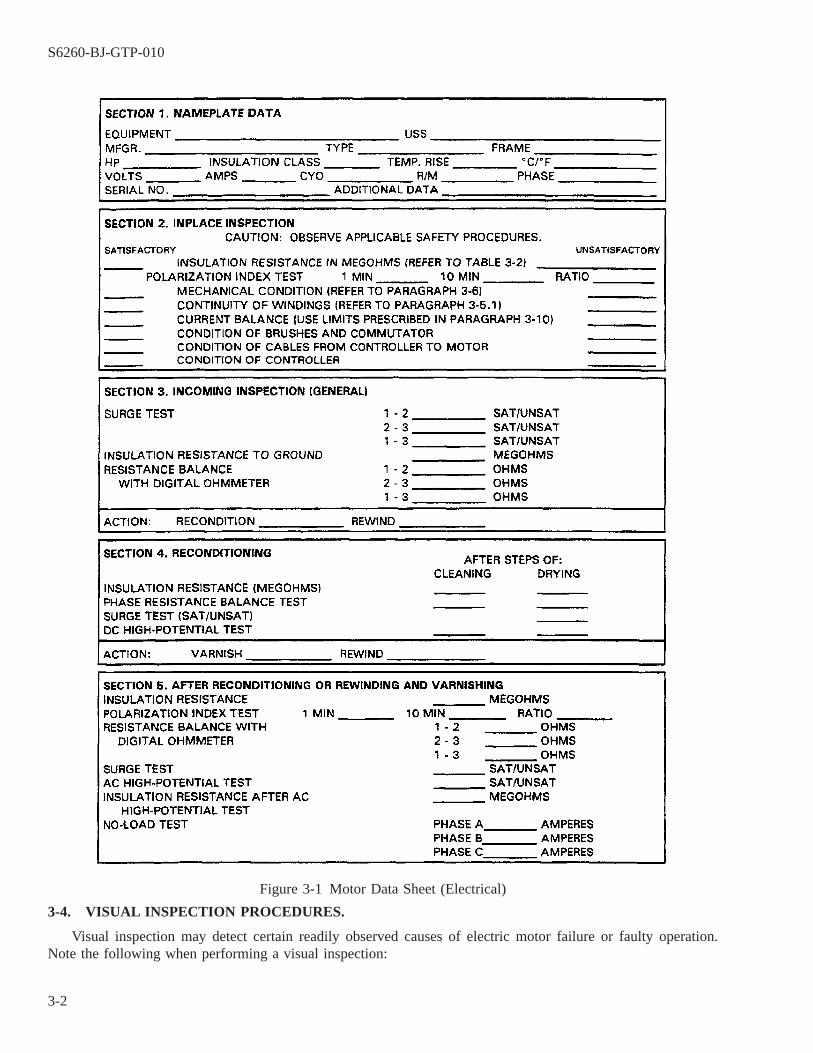
3-4. VISUAL INSPECTION PROCEDURES.
Visual inspection may detect certain readily observed causes of electric motor failure or faulty operation.Note the following when performing a visual inspection:
Figure 3-1 Motor Data Sheet (Electrical)
S6260-BJ-GTP-010
3-2

WARNING
DANGER: Electric motors use high voltages capable of causing death. Useextreme caution when working near the power source and load components.Always use proper safety equipment to include such items as insulated mat-ting and protective gloves. Observe correct tag-out procedures.
WARNING
Take care when using metal tools around an electric motor with energizedlines. Handle tools properly to avoid dropping them. Mishandling can acci-dentally cause a short circuit which could harm personnel or damage equip-ment.
a. Inspect windings and adjacent areas for mechanical damage, or discolored or burned areas visible throughaccess or ventilation openings.
b. Rotate the motor shaft by hand, if possible. Check freedom of rotation, absence of rubbing or binding, andexcessive end or side play.
c. Remove the cover of the terminal box and inspect the leads and the taped lead connections for signs of over-heating or mechanical damage. Do not disassemble the taped connections unless there is evidence of damage.
NOTE
A motor winding should be rewound if obvious physical damage or a burnedsection is detected. It is recommended to rewind a motor when the motor wind-ing insulation is deteriorated. The presence of excessive cracking, flaking of thevarnish, or bare copper will indicate deterioration.
3-5. ELECTRICAL TEST PROCEDURES.
After a visual inspection, perform the following tests:
3-5.1 Winding Continuity and Resistance Test. Use appropriate schematic diagrams of the motor being testedto locate the proper windings and connections. Perform resistance measurements with the motor at room tem-perature using a digital ohmmeter (paragraph 2-15). Perform initial measurements at the motor controller. Recordresistance values on a motor data sheet (electrical) (figure 3-1).
a. A resistance value considerably greater than specified limits indicates a lack of continuity and represents anopen circuit or a high resistance connection. If this condition is discovered, isolate the motor and measurewinding resistance at the motor. Check terminal lugs for proper attachment to motor leads. If the windingresistance remains high, the motor requires rewind.
b. For three-phase motors, conduct a phase resistance balance test. See paragraph 2-15, digital ohmmeter, for thetest procedure and resistance balance acceptability criteria. Windings not meeting the balance criteria requirerewind.
S6260-BJ-GTP-010
3-3

3-5.2 Insulation Resistance Test.
a. Remove the cover of the terminal connection box and tag the leads, if necessary, before disconnecting them.
b. Measure insulation resistance, using a 500-volt megohmmeter. See paragraph 2-4 and paragraph 2-8 for useof the megohmmeter.
NOTE
Insulation resistance is measured in megohms and is affected by several condi-tions. These conditions are saturation or contamination with moisture, carbondust, dirt, or oil. Deteriorated insulation caused by age or by temperatures greaterthan the class of insulation used can also reduce the value of insulation resis-tance.
The values of insulation resistance for ac generators and motors in table 3-2serve as a guide to determine when cleaning, drying, or overhaul is necessary.For further explanation of resistance measurement, see NAVSEA S0986-KC-STM-010/CH 300.
(1) Take resistance measurements on the components of the circuits within the machine. Measure internalleads, collector rings, etc.
(2) Clean any defective parts and recheck insulation resistance.
NOTE
The cause of low insulation resistance is often a defective lead or a deposit ofdirt on exposed terminals or brush insulation.
If end bells are removed, bearings must be replaced.
(3) Record all measurements on a motor data sheet (electrical) (figure 3-1).
(4) Disassemble the motor, as necessary, if the insulation resistance value is lower than those shown in table3-2. Disassembly will permit in-place cleaning or removal to the shop for thorough reconditioning. Seeparagraph 4-16 on moving motors.
3-5.3 Controller and Cable Insulation Resistance Test. If the motor measurements are satisfactory, ensure thatcable and controller insulations are in satisfactory condition.
a. Measure the insulation resistance of the cable to ground and between phases with a megohmmeter. Check themotor and motor power cable separately.
b. Record all measurements on a motor data sheet (electrical) (figure 3-1).
Table 3-2 Insulation Resistance for Generators and Motors
AC GENERATORS AND MOTORS OTHER THAN PROPULSION
Insulation Resistance (megohms at 25° C) 1
Circuit Minimum forOperation
After Cleaning inShip
After Recndtn AfterRewinding
Stator circuit of generators and motors 0.2 1.0 25 200
S6260-BJ-GTP-010
3-4

Table 3-2 Insulation Resistance for Generators and Motors - Continued
Rotor circuit of wound rotor induction motors 0.1 0.5 25 100Field circuit of generators or of synchronousmotors
0.4 2.0 25 400
Stator circuit of motors with sealed insulationsystem
2.0 25 500 1000 2
100 3
DC GENERATORS AND MOTORS (EXCEPT PROPULSION AND AUXILIARY GENERATORS FOR SUB-MARINES) INCLUDING EXCITERS
Insulation Resistance (megohms at 25° C) 1
Circuit Minimum forOperation
After Cleaning inShip
After Recndtn AfterRewinding
Complete armature circuit 2 , a 0.1 0.5 1.0 100Armature alone 0.2 1.0 2.0 200Armature circuit less armature 2 , b 0.2 1.0 2.0 200Complete field circuit 0.5 1.5 2.5 200
1Values are for machines rated 500 volts or less. For machines having a rated voltage (E) greater than 500 volts,multiply all values given in the table by E/500.
2Minimum acceptable value with winding dry, before and after submergence test.
3Minimum acceptable value during 24-hour fresh water submergence test.
1Values are for machines rated 250 volts or less. For machines having a rated voltage (E) greater than 250 volts,multiply all values given in the table by E/250.
2Small machines usually have one of the shunt field leads connected internally to the armature circuit. To avoiddisassembly in such cases, the complete armature circuit and the complete field circuit may be measured with-out breaking this connection. If necessary, the armature can be isolated by lifting the brushes.
aWith brushes left in place, the complete armature circuit will include armature, armature circuit, and the perma-nent connected field circuit. The values given in the table for the complete armature circuit will apply.
bWith brushes lifted, the armature circuit, less armature and the complete field circuit, will be measured. The val-ues given in the table for armature circuit, less armature, will apply.
3-6. MECHANICAL INSPECTION PROCEDURES.
3-7.
Basic inspection procedures require three steps:
3-7.1 Perform a general mechanical test and inspection to determine what action is required to restore the motorto reliable working order. When the cause of the faulty operation is determined, correct it to prevent future prob-lems. Visual inspection may detect certain readily observable causes of motor failure or faulty operation. On-the-spot adjustment or repair frequently solves the problem and eliminates unnecessary removal and disassembly ofa motor.
3-7.2 If the problem is not easily observed, check the motor, section by section, until the fault is located.
S6260-BJ-GTP-010
3-5
3-7.3 Before conducting repair work, review the evidence to determine all factors that may have contributed tobearing failure. Factors may include lack of lubrication, incorrect mechanical fitup, misalignment, and contami-nants. It is also necessary to determine whether defects discovered are the cause or the result of the malfunction.
WARNING
High voltages capable of causing death are used in electric motors. Useextreme caution when working near the power source and load components.Always wear proper safety equipment. Observe correct tag-out procedures.
CAUTION
Take care when using any conducting tool around an electric motor withenergized lines. Handle tools properly to avoid dropping them. Mishandlingcan accidentally cause a short circuit that could damage equipment.
NOTE
It may be necessary to have the machinist’s mate or engineman disconnect thecoupling of the driven unit to test the motor.
Ensure that the motor is tagged out before grabbing the shaft or removing thecoupling.
3-8. VISUAL INSPECTION.
The motor data sheet (mechanical) (figure 3-2) provides a convenient method of keeping a permanent recordof important mechanical facts about a motor. Record the general condition of the motor in the spaces providedduring in-place test and inspection.
a. Turn the motor shaft by hand or observe coastdown to check for freedom of rotation (figure 3-3).
NOTE
The trouble may be either in the motor or the driven machine (pump, compres-sor, etc.) if the shaft binds.
b. Listen to the motor as it is coasting down. This is one way of directly tracing the source of vibration, particu-larly in the case of a large motor generator set. Actual coastdown time depends upon the motor size and itsmechanical condition.
c. Cautiously touch the housings to check for excessive heating of the bearings.
S6260-BJ-GTP-010
3-6
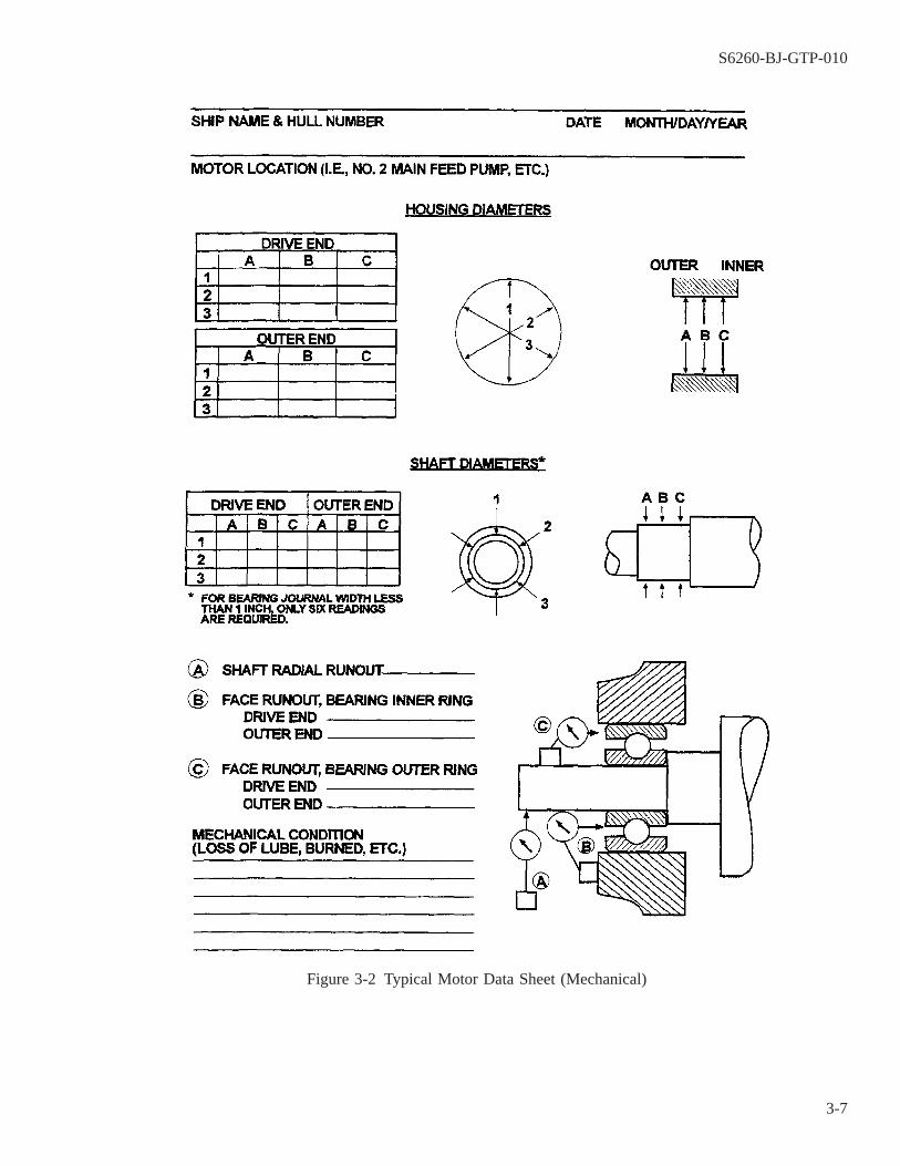
Figure 3-2 Typical Motor Data Sheet (Mechanical)
S6260-BJ-GTP-010
3-7
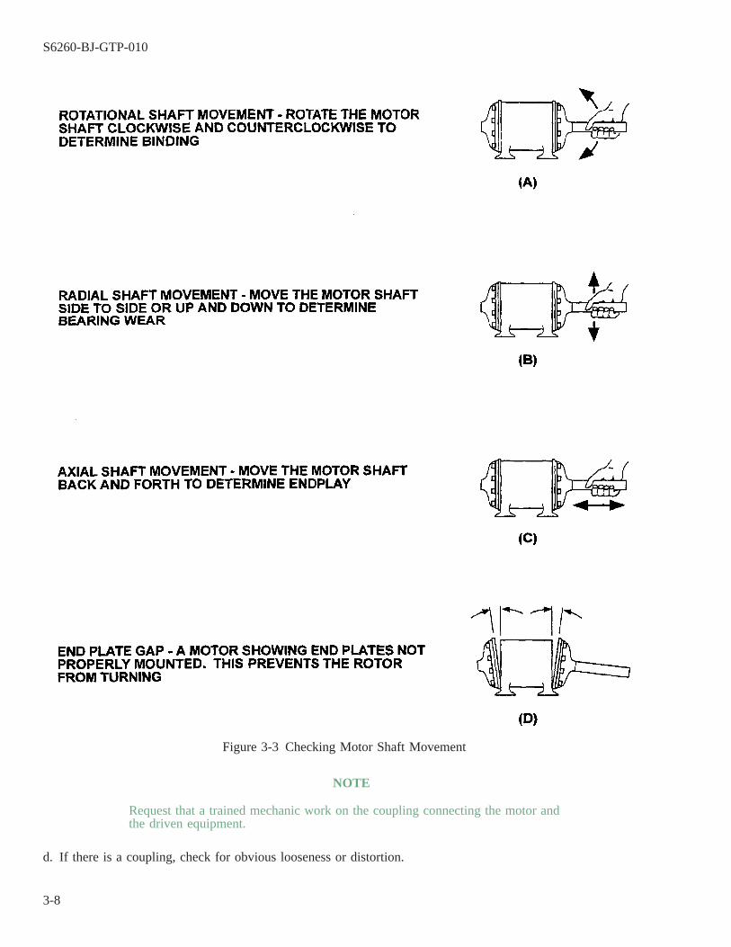
NOTE
Request that a trained mechanic work on the coupling connecting the motor andthe driven equipment.
d. If there is a coupling, check for obvious looseness or distortion.
Figure 3-3 Checking Motor Shaft Movement
S6260-BJ-GTP-010
3-8

NOTE
A worn bearing or motor shaft is indicated if the shaft can be moved radially.
e. Check the motor shaft for radial movements (figure 3-3).
f. Check the motor frame for loose or improperly installed end plates and bearing caps.
g. Check for cracked, loose, or missing bolts or capscrews. Ensure that the balancing rings are secure.
h. Check for ″sound shorts″ on sound-mounted equipment like piping, cables, or other loosely connected equip-ment. Examine the condition of the mountings and holddown bolts. Check the expiration date of the mountsand check for excessive deflection.
i. Make radial and axial vibration records. Use analysis methods described in NAVSEA 0900-LP-060-2020.
NOTE
Not all motor end bells have removable bearing end caps.
3-9. BEARING RUNOUT TEST PROCEDURES.
Use the following procedures to test bearing runout:
a. Measure shaft motion axially using dial indicators. Recommended maximum axial runout is shown in table3-3.
Table 3-3 Recommended Maximum Axial Runout for Bearing, Shaft, andHousing Assemblies Using Quiet Bearings
BEARING BORE CODE BEARING BOREMAXIMUM RECOMMENDED
AXIAL RUNOUT OFASSEMBLY
200 & 300 Series Inches mm00 to 03 0.3937 to 0.6693 10 to 17 0.0004 inch04 to 10 0.7874 to 1.9685 20 to 50 0.0005 inch11 to 17 2.1654 to 3.3465 55 to 85 0.0010 inch18 to 26 3.5433 to 5.1181 90 to 130 0.0015 inch
Source: NAVSEA S9086-HN-STM-010/CH 244, ″Bearings, Ball and Roller.″
b. Remove one or both motor bearings caps, if they are accessible. Attach a dial indicator magnetic base firmlyon the motor frame. Set the contact point on the face of the bearing inner ring (figure 3-4).
c. Rotate the shaft slowly with an even turning force. Be careful that it does not move toward either end.
NOTE
Dial indicator variations in bearing runout measurements at one end of a motorwill also indicate bearing misalignment at the other end. Misalignment mayoccur in inner or outer bearing rings at either end of the motor. The amount ofaxial vibration caused by misalignment depends on the type of bearing mountingused and the axial and radial loads on each bearing. Excessive runout indicatesa problem which may not only cause vibration but may also severely lower thereliability of the motor.
d. Reassemble the motor bearings and caps if bearing runout is within tolerance levels.
S6260-BJ-GTP-010
3-9
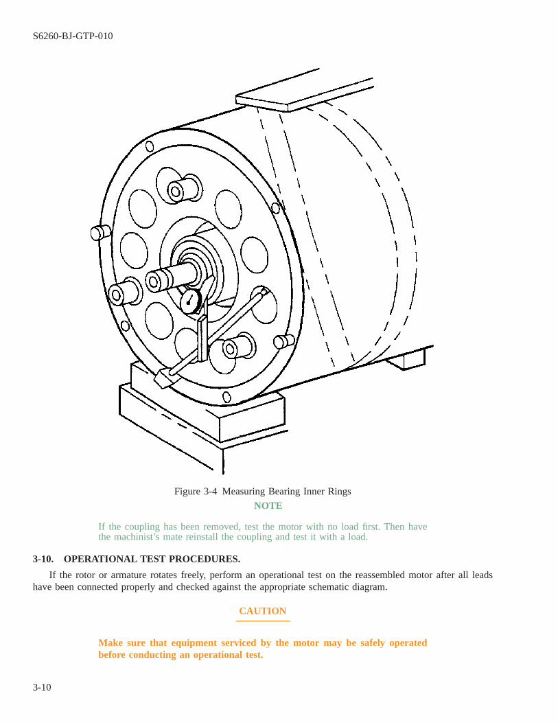
NOTE
If the coupling has been removed, test the motor with no load first. Then havethe machinist’s mate reinstall the coupling and test it with a load.
3-10. OPERATIONAL TEST PROCEDURES.
If the rotor or armature rotates freely, perform an operational test on the reassembled motor after all leadshave been connected properly and checked against the appropriate schematic diagram.
CAUTION
Make sure that equipment serviced by the motor may be safely operatedbefore conducting an operational test.
Figure 3-4 Measuring Bearing Inner Rings
S6260-BJ-GTP-010
3-10
a. Remove the safety tag and energize the circuitry.
b. Start the motor at its normally used pushbutton station.
c. Measure phase currents if the equipment is ac. Use a clamp-on ammeter (paragraph 2-25) or a clamp-on mul-timeter (paragraph 2-29).
NOTE
The current in any phase, at rated load, shall not differ from the arithmetic aver-age of the maximum and minimum phase current by more than 10 percent for 11/2-horsepower motors or less; by more than 7 1/2 percent for 2-and3-horsepower motors; and by more than 5 percent for motors over 3 horsepower.For submarine motors, at no load, the maximum deviation of any phase shall notexceed 3 percent of the average no-load current.
d. Record all measurements on a motor data sheet (electrical) (figure 3-1).
e. If the current imbalance is excessive, check the incoming phase voltage at the controller with the motor deen-ergized. Imbalanced voltage indicates improper phase balance from the motor’s power source. Incoming volt-age cannot vary more than ± 10 percent and must be less than ± 3 percent difference between phases.
WARNING
Electric motors use high voltages capable of causing death. Use extremecaution when working near the power source and load components. Alwaysuse proper safety equipment to include such items as insulated matting andprotective gloves. Observe correct tag-out procedures.
Take care when using metal tools around an electric motor with energizedlines. Handle tools properly to avoid dropping them. Mishandling can acci-dentally cause a short circuit which could harm personnel or damage equip-ment.
f. Check the controller and cable for loose or high resistance connections if voltage imbalance is not causing theimbalanced phase currents. Correct any faults.
g. Measure winding resistances using a digital ohmmeter (paragraph 2-15).
h. Record all measurements on a motor data sheet (electrical) (figure 3-1).
NOTE
A motor must be rewound if unbalanced currents are drawn by the motor andthey are caused by shorted, grounded, or open sections of the winding; byunequal winding resistances; or the cause is unknown.
i. Deenergize the equipment and reinstall the motor terminal box cover upon completion of the test.
j. If the motor requires repair or overhaul and the problem cannot be corrected in place, remove the motor tothe shop. See Chapter 4 on rigging and transporting motors.
S6260-BJ-GTP-010
3-11 / (3-12 Blank)

3-12@@FIpgtype@@BLANK@@!FIpgtype@@
CHAPTER 4
RIGGING AND TRANSPORTATION
4-1. SCOPE.
This chapter contains information on the rigging and transportation of electric motors. Topics include:
4-1.1 Preparation for moving (paragraph 4-2).
4-1.2 Rigging fundamentals (paragraph 4-7).
4-1-3 Transporting the motor (paragraph 4-15).
4-2. PREPARATION FOR MOVING.
4-3.
Carefully inspect the motor, and determine the type of mounting employed. Be sure to:
a. Note the size and weight of the motor.
b. Ensure that the motor lifting eyebolts are firmly mounted and secure.
c. Check the motor mounting feet to determine if the foundation bolts are corroded.
NOTE
Only a machinist’s mate should work on the coupling connecting the motor andthe driven equipment. This applies to all pertinent steps in this chapter.
4-4. MOTOR LOCATION AND REMOVAL ROUTE.
Review the motor’s location and nearby machinery and plant layout. Select the best route for moving themotor to the repair activity shop, as follows:
4-4.1 Look for anything that might interfere with motor removal: ladders, handrails, deck plates, etc.
4-4.2 Check headroom. Look for piping systems and overhead barriers that might interfere with movement.
4-4.3 Check the ship’s blueprints and manuals and the manufacturer’s manuals for information concerning thearrangement of machinery on a particular ship. Be familiar with the location of engineering equipment, and thelayout of piping and electrical systems.
4-5. RIGGING INSPECTION.
Check all rigging accessories and weight-moving equipment.
4-5.1 Ensure that accessories are inspected for wear and for suitability for use. Accessories include wire rope andwire rope attachments (e.g., clamps and fittings), hooks, shackles, slings, straps, and hitches.
S6260-BJ-GTP-010
4-1
4-5.2 Inspect weight-holding and weight-moving equipment. Review inspection records maintained by experi-enced rigging personnel to ensure the safe condition of this equipment. Inspect dollies, pallets, blocks and tack-les, chain hoists, comealongs, winches, cranes, and derricks.
NOTE
QA personnel are responsible for ensuring proper testing of padeyes.
4-5.3 Ensure that padeyes have been tested for the weight specified.
WARNING
High voltages capable of causing death are used in electric motors. Useextreme caution when working near the power source and load components.Always wear safety equipment. Observe correct tag-out procedures.
CAUTION
Take care when using any conducting tool around an electric motor withenergized lines. Handle tools properly to avoid dropping them. Mishandlingcan accidently cause a short circuit that could damage equipment or injurepersonnel.
4-6. DISCONNECTING THE MOTOR.
To remove the motor from its mount:
WARNING
To ensure that it is working properly, use only a voltmeter that has beenchecked out on a known live circuit.
a. Use a voltmeter to check the motor leads before disconnecting them. Test the ″live″ side first, then the ″dead″side. Then, retest the ″live″ side.
b. Identify and tag the motor leads before disconnecting them. Disconnect the electrical cables from the motorand controller. Tape and tie them back and out of the way.
NOTE
Dispose of oil according to the individual ship’s procedure.
c. Drain all lube oil reservoirs. Close any openings.
d. Cap, mask, or cover all openings to keep out foreign matter.
S6260-BJ-GTP-010
4-2
NOTE
Remove the motor, shock mounts, bedplate or foundation, and auxiliary pump (ifany) as a unit whenever possible.
e. Follow the appropriate manufacturers disassembly procedure to uncouple the motor shaft. Use the propertools.
f. Discard the grid, if the coupling is a grid type.
g. Mark and store the coupling hub cover bolts.
h. Remove the motor foundation bolts. Use the proper tools.
NOTE
Drill or machine-grind badly corroded foundation bolts. Do not chisel them out.
i. Pull or drill out tapered dowel pins which are set at an angle. Remove, identify, and safely store shims fromunder the motor feet.
j. Place and attach a pipe extension on the shaft to protect it from damage.
k. Carefully inspect each nut and bolt or other fastening device on the whole assembly to ensure that they areproperly installed and tight. Do this before handling.
NOTE
The motor is now safely disconnected. All reusable parts and components havebeen marked and stored. It is ready to rig and transport.
4-7. RIGGING FUNDAMENTALS.
4-8. HANDLING PROCEDURES AND PRECAUTIONS.
Observe the following procedures and precautions in rigging the motor:
NOTE
Ensure that each piece of rigging equipment is capable of holding the entireweight of the unit being rigged and transported.
4-8.1 Know the safe working load of all rigging lines, slings, and hoists. Also know the weight and size of themotor or coupled unit.
4-8.2 Handle coupled units as an assembly. Do not lift the entire weight of the unit at only one point, or by onlyone component.
4-8.3 Do not attach a sling or other rigging accessory which will distort, bend, or otherwise damage the equip-ment.
4-8.4 Never lift any component by the part which might rotate, such as the motor shaft.
S6260-BJ-GTP-010
4-3

4-8.5 Never lift a unit by its end bells or mounting flanges.
4-8.6 Avoid bumping and jarring the motor while handling it.
4-8.7 Ensure that supporting structures, such as A-frames, shoring, staging, or rigging, are removed before han-dling assembled units on a bedplate.
CAUTION
Handle low-noise electric motors carefully. Handling damage can cause highvibration levels and reduce mechanical or electrical reliability.
4-8.8 Handle components carefully to avoid damaging critical parts. Undue stress on noise-critical machinery candamage bearings or result in imbalance or misalignment.
4-9. RIGGING COMPONENTS.
Wire rope is vital in rigging. It can be used in various tackle and lever combinations to form the rigging tolift and move heavy loads. Many different attachments are used for rigging, including wire rope clamps and fit-tings, hooks, and shackles.
4-10. WIRE ROPE CLAMPS.
Clamps are put on a wire rope to form a loop. The loop may be attached to other wire rope fittings, such asshackles or hooks, so that the wire rope can be affixed to weight-lifting equipment (figure 4-1 and figure 4-2).The wire rope clamp forms a temporary eye splice. A single clamp consists of a U-bolt, saddle, and nuts. Thereis only one correct method for applying these clamps to wire rope. Follow these precautions when using rigs withwire rope clamps:
4-10.1 Ensure that all U-bolts bear against the bitter end of the rope.
4-10.2 Tighten the clamp after the rope is taut.
4-10.3 Tighten the clamps daily on operating ropes. Inspect the ropes carefully at clamped points.
S6260-BJ-GTP-010
4-4
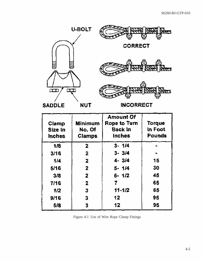
Figure 4-1 Use of Wire Rope Clamp Fittings
S6260-BJ-GTP-010
4-5

NOTE
The size is stamped on the saddle between the two holes.
4-10.4 Ensure that the correct size and number of clamps are used to obtain maximum strength in the eye splice.
Figure 4-2 Wire Rope Fittings
S6260-BJ-GTP-010
4-6
4-10.5 Space the clamps to provide a good hold on the wire rope.
4-11. WIRE ROPE FITTINGS.
Fittings are attached to the ends of wire rope. They permit easy connection to other wire ropes, chains,padeyes, or heavy equipment. The type of lifting to be done will determine the kinds of fittings used.
4-12. HOOKS AND SHACKLES.
Hooks and shackles are a useful means of hauling or lifting loads. They may be used without tying directlyto a load by using a line, wire rope, or chain. When using hooks and shackles, follow these precautions:
CAUTION
Hooks may straighten out and drop their load when overloaded. A hookshould NEVER be rebent and put back in service if it has been stretched orspread by overloading. It should be destroyed by cutting it in half with acutting torch.
a. Shackles should be used for loads too heavy for hooks to handle.
b. Visually inspect hooks before lifting any full-rated load. To determine if a hook can lift a full load, measurethe shank of the hook and refer to an appropriate chart showing hook capacity.
c. When there is danger of an open hook catching on an obstruction, use hooks that close.
NOTE
These hooks have rugged positive-action safety latches. The latch has a power-ful snap spring that prevents jarring the load from the hook.
d. Use mousing to close the open section of a hook (figure 4-3A) if a safety hook is not available. This will keepslings, straps, etc., from slipping off the hook. Hooks may be moused with rope yarn or seizing wire, or ashackle (figure 4-3B). Make 8 or 10 wraps around both sides of the hook when using rope yam or wire. Makeseveral turns with the yarn around the sides of the mousing. Tie the ends securely to finish off.
e. Mouse shackles when there is a danger of the shackle pins working loose and coming out because of vibra-tion. To mouse a shackle, make several turns with seizing wire through the eye of the pin and around the bowof the shackle (figure 4-3C).
4-13. CHAIN HOISTS.
Chain hoists are a convenient means of hoisting heavy objects. The load can remain stationary withoutrequiring attention when a chain hoist is used. The slow lifting travel of a chain hoist is also advantageous. Itpermits short movement, accurate height adjustments, and cautious handling of loads. The spur gear hoist (fig-ure 4-4A) is best for ordinary operations which require frequent hoist use, and where a minimum number of per-sonnel are available to operate it. The differential hoist is suitable for light loads, and when occasional use of thehoist is involved (figure 4-4B). Observe the following safety precautions when using chain hoists:
S6260-BJ-GTP-010
4-7

CAUTION
The lower hook is usually the weakest part of a chain hoist. Spreading in thehook is a signal to the operator that the chain hoist is nearing the overload-ing point. Therefore, close observation by the operator is necessary to detectany sign of overloading in time to prevent damage to the hoist. Ordinarily,pull exerted by one or two people on a chain hoist is not enough to overloadit.
a. Always inspect the chain hoist’s mechanisms before use to ensure safe operation.
b. Replace any hook that shows signs of spreading or excessive wear.
c. The chain hoist has probably been overloaded if the links of the chain are distorted. In such cases, do not usethe hoist, and see that it is condemned and removed from service immediately.
Figure 4-3 Mousing Wire Rope Fittings
S6260-BJ-GTP-010
4-8

4-14. WINCHES.
Winches are frequently used as a power source for hoisting rigs, particularly for heavy-duty derricks. A winchis a device for hoisting or hauling materials or objects. It has one or more drums on which line or wire rope iswound. Hand-operated and engine-driven winches are available. A single-drum, hand-operated winch is suitablefor lifting light loads. Single-drum hand-operated winches are available in capacities such as 2, 5, 6 and 15 tons(figure 4-5). Hand-operated winches are generally mounted near the foot of the rig, where they can be operatedefficiently.
Figure 4-4 Types of Chain Hoists
S6260-BJ-GTP-010
4-9
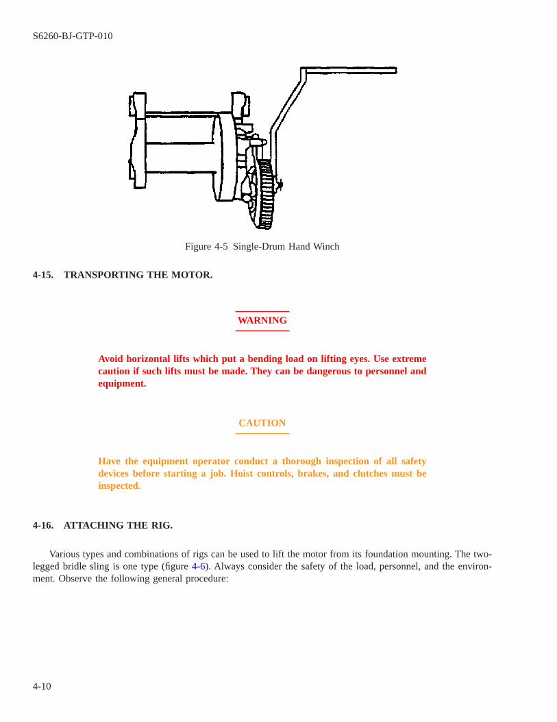
4-15. TRANSPORTING THE MOTOR.
WARNING
Avoid horizontal lifts which put a bending load on lifting eyes. Use extremecaution if such lifts must be made. They can be dangerous to personnel andequipment.
CAUTION
Have the equipment operator conduct a thorough inspection of all safetydevices before starting a job. Hoist controls, brakes, and clutches must beinspected.
4-16. ATTACHING THE RIG.
Various types and combinations of rigs can be used to lift the motor from its foundation mounting. The two-legged bridle sling is one type (figure 4-6). Always consider the safety of the load, personnel, and the environ-ment. Observe the following general procedure:
Figure 4-5 Single-Drum Hand Winch
S6260-BJ-GTP-010
4-10

WARNING
DO NOT use a heavily corroded eyebolt.
a. Attach a safety hook or shackle to the motor-mounted eyebolts to rig lifting gear to the disconnected motor.
NOTE
Be sure that the tag line is long enough and that it remains free of loops andknots.
b. Attach a steadying tag line to guide the load and prevent it from moving out of control.
Figure 4-6 Two-Legged Bridle Sling
S6260-BJ-GTP-010
4-11

WARNING
Before giving a hoisting signal, check to ensure that all members of the crewhave removed their hands from slings, hooks, and loads. See that all person-nel are clear of the lifting rig and tag lines, and that loose parts or objectsare properly secured.
Know the load capacity of the rig being used. Ensure that its capacity is notexceeded.
c. Ensure that the hoist equipment operator knows what is to be done.
d. Ensure that each crew member wears the proper safety apparel (e.g., hard hats, gloves, and safety boots).
4-17. HOISTING.
When hoisting, follow these procedures:
Figure 4-7 Two-Legged Bridle Sling Lifting Motor with Safety Hook
S6260-BJ-GTP-010
4-12
a. Raise a heavy load a few inches. Let it hang for a moment to see if the load is balanced before continuing thelift. Be sure that the brakes of the hoist function properly. Watch the load as it is hoisted (figure 4-7).
b. Gently lift the motor and recover any shims which might be under the mounting feet. Shims must be tagged,identified, and stored.
CAUTION
Do not use a hammer to remove the coupling.
c. Place pallet on the deck where the motor can be temporarily lowered for removal of the shaft coupling.
d. Stop the motor before it is completely lowered and wrap the shaft with cotton waste. Bolt a pipe extension tothe shaft for protection.
4-18. TRANSPORTATION.
Various methods of transporting the motor may be used after it has been disconnected and lifted from itsfoundation mounting. A dolly is preferred. Other methods may be used, depending on the size and weight of themotor. Pallets and rollers make the movement of heavy loads easier. Skids with rollers may also be used. Thepallet or skid can be dragged along by attaching a fiber or wire rope rig and a winch or come-along at some dis-tant padeye. Use the following general procedures:
WARNING
Make sure that all deckplate openings have been roped off along the trans-portation route.
a. Use a dolly to transport the motor, if possible. Use the welded test-pulled padeyes located throughout the shipif the motor is too large.
b. A motor can be moved through the ship by ″yard and stay″ rigging when a dolly cannot be used. Two hoistsare needed to yard and stay.
(1) Inspect the padeye of the motor to ensure that it is in good condition.
(2) Attach one shackle in the padeye which is capable of passing the clevis pin to two other shackles.
(3) To the shackle in the motor padeye, attach two shackles capable of receiving the hoist hooks.
(4) Rig one hoist and fall directly over the motor. This hoist is the yard hoist (figure 4-8A).
(5) Pass the hoist hook through one shackle and mouse the hook.
(6) Rig a second hoist a few feet downstream from the first. The distance from the first hoist will depend onthe overhead height and length of the hoist. this is the stay hoist (figure 4-8A).
(7) Pass a second hoist hook through the second shackle and mouse the hook.
(8) Lift the load with a yard hoist (figure 4-8B).
(9) Heave in the stay hoist (figure 4-8C).
(10) Slowly slack the yard and transfer the motor to the stay as the stay hoist takes the strain.
S6260-BJ-GTP-010
4-13
NOTE
The stay becomes the yard for the second move when the stay has the motorweight (figure 4-8D).
(11) Move the original yard downstream from the original stay when the yard is completely slack (figure4-8E).
(12) Continue moving the hoist until the motor is topside or in position to be lifted over the side.
NOTE
Use either nylon lifting straps or a net around the motor when the motor doesnot have lifting eyebolts.
c. Ensure that knots do not slip when using nylon straps. Use bowline, square, clove, and barrel hitch knotswhere appropriate.
d. Use a net under the load for additional safety.
e. See that all rigging gear is returned or properly stored when not in use.
S6260-BJ-GTP-010
4-14

4-19. MOTOR ROTOR TRANSPORT.
Follow these steps when moving a motor rotor:
Figure 4-8 Yard and Stay Method
S6260-BJ-GTP-010
4-15

NOTE
Follow the safety precautions discussed in paragraph 4-8 when only the motorrotor is being transported.
4-19.1 Protect the rotor shaft with cotton waste and a pipe extension.
NOTE
Special protective fixtures for rotor shafts are constructed so they can be used ona variety of rotor shafts. A shaft protection fixture (figure 4-9) is made of a cir-cular plate that fits flat against the motor end bell with a hole in it through whichthe rotor shaft would extend. An oversized piece of pipe or rigid tubing is weldedto the center of the plate and perpendicular to it. Cotton waste is placed aroundthe rotor shaft prior to placing the shaft protection fixture around the rotor shaftto protect it from burrs, nicks, and scratches.
4-19.2 Use rotor slings that have been fabricated ahead of time. The rotor sling is used to lift the shaft protec-tion fixture.
NOTE
Properly made rotor slings will accommodate several size rotors. Figure 4-10shows a typical rotor sling. The sling has an eye on each end and is made witheither a hand or mechanical splice.
S6260-BJ-GTP-010
4-16

Figure 4-9 Shaft Protection Fixture
S6260-BJ-GTP-010
4-17

Figure 4-10 Typical Rotor Sling
S6260-BJ-GTP-010
4-18
CHAPTER 5
IN-SHOP ELECTRIC MOTOR INSPECTION AND DISASSEMBLY
5-1. SCOPE.
This chapter contains information on electric motor in-shop inspection and disassembly procedures. Topicsinclude:
5-1.1 Electric shop records (paragraph 5-2).
5-1.2 Initial mechanical inspection procedures (paragraph 5-7).
5-1.3 Disassembly procedure (paragraph 5-11).
5-1.4 Electrical inspection (paragraph 5-18).
5-2. ELECTRIC SHOP RECORDS.
5-3.
The recordkeeping system in an electric motor repair shop must ensure a smooth flow of vital inspection andtest information so that motors can be repaired correctly and returned to operation in minimum time. Some of thedocumentation required will accompany the motor in a work package; other documents must be completed in theshop.
5-4. WORK PACKAGE.
A considerable amount of documentation should accompany the motor, either as part of a work package orseparately with the motor. Pertinent documents include:
5-4.1 Automated Work Request (AWR). An AWR is prepared by the tended unit. It should provide all neces-sary motor identification information, a description of work requested, and the name of a contact person.
5-4.2 Maintenance Planning and Estimating Form. This form, OPNAV 4790/2P, is prepared by the planningand estimating office of the IMA.
5-4.3 Formal Work Procedure (FWP). This document provides clear, concise, and technically correct instruc-tions for performing the assigned maintenance task.
5-4.4 Quality Assurance Documents. The IMA quality assurance office will add to the work package any qual-ity assurance documentation required in the inspection, repair, and testing of the motor.
5-4.5 In-place Mechanical and Electrical Data Sheets. If an in-place inspection (ship check) has been accom-plished, the mechanical and electrical motor data sheets should accompany the work package and/or the motor.These records are used to enter the cause and extent of damage to electrical motors noted during any in-placeinspection. These two motor data sheets are also used in the shop for in-shop inspections and test records, andinclude final (postoverhaul) inspections. The inspection determines whether the motor has been properly recon-ditioned and rewound and is ready for return to operational service.
S6260-BJ-GTP-010
5-1
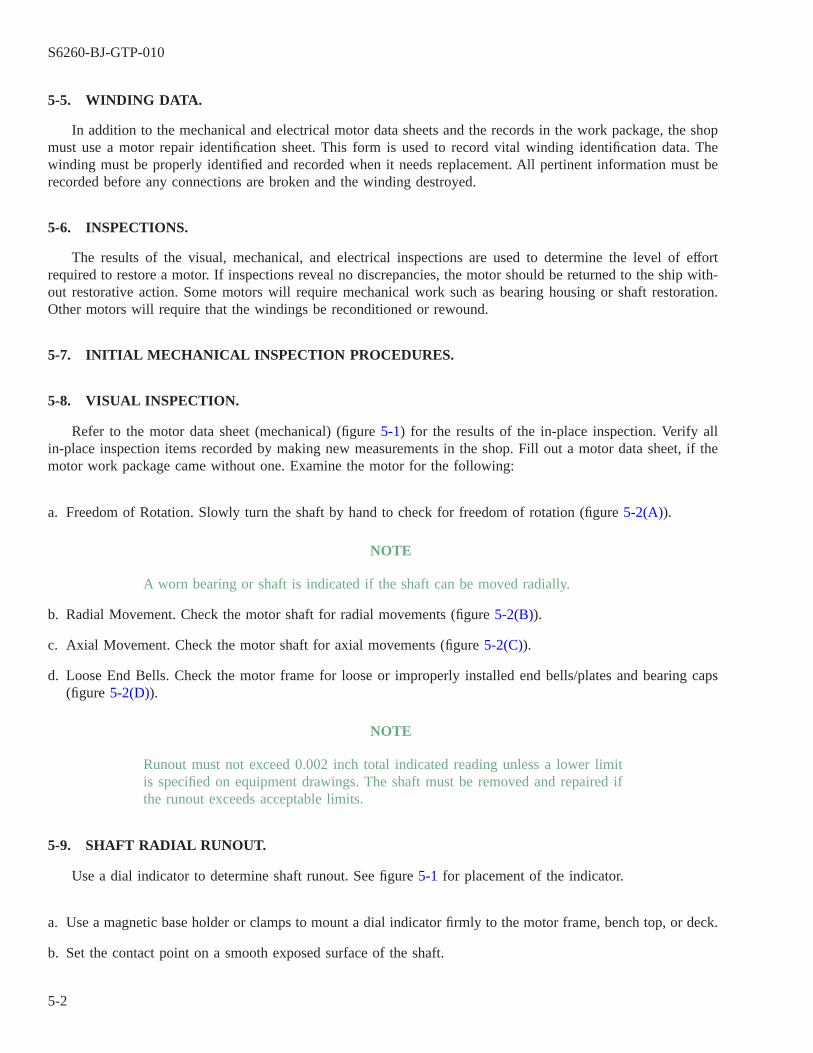
5-5. WINDING DATA.
In addition to the mechanical and electrical motor data sheets and the records in the work package, the shopmust use a motor repair identification sheet. This form is used to record vital winding identification data. Thewinding must be properly identified and recorded when it needs replacement. All pertinent information must berecorded before any connections are broken and the winding destroyed.
5-6. INSPECTIONS.
The results of the visual, mechanical, and electrical inspections are used to determine the level of effortrequired to restore a motor. If inspections reveal no discrepancies, the motor should be returned to the ship with-out restorative action. Some motors will require mechanical work such as bearing housing or shaft restoration.Other motors will require that the windings be reconditioned or rewound.
5-7. INITIAL MECHANICAL INSPECTION PROCEDURES.
5-8. VISUAL INSPECTION.
Refer to the motor data sheet (mechanical) (figure 5-1) for the results of the in-place inspection. Verify allin-place inspection items recorded by making new measurements in the shop. Fill out a motor data sheet, if themotor work package came without one. Examine the motor for the following:
a. Freedom of Rotation. Slowly turn the shaft by hand to check for freedom of rotation (figure 5-2(A)).
NOTE
A worn bearing or shaft is indicated if the shaft can be moved radially.
b. Radial Movement. Check the motor shaft for radial movements (figure 5-2(B)).
c. Axial Movement. Check the motor shaft for axial movements (figure 5-2(C)).
d. Loose End Bells. Check the motor frame for loose or improperly installed end bells/plates and bearing caps(figure 5-2(D)).
NOTE
Runout must not exceed 0.002 inch total indicated reading unless a lower limitis specified on equipment drawings. The shaft must be removed and repaired ifthe runout exceeds acceptable limits.
5-9. SHAFT RADIAL RUNOUT.
Use a dial indicator to determine shaft runout. See figure 5-1 for placement of the indicator.
a. Use a magnetic base holder or clamps to mount a dial indicator firmly to the motor frame, bench top, or deck.
b. Set the contact point on a smooth exposed surface of the shaft.
S6260-BJ-GTP-010
5-2

Figure 5-1 Motor Data Sheet (Mechanical)
S6260-BJ-GTP-010
5-3
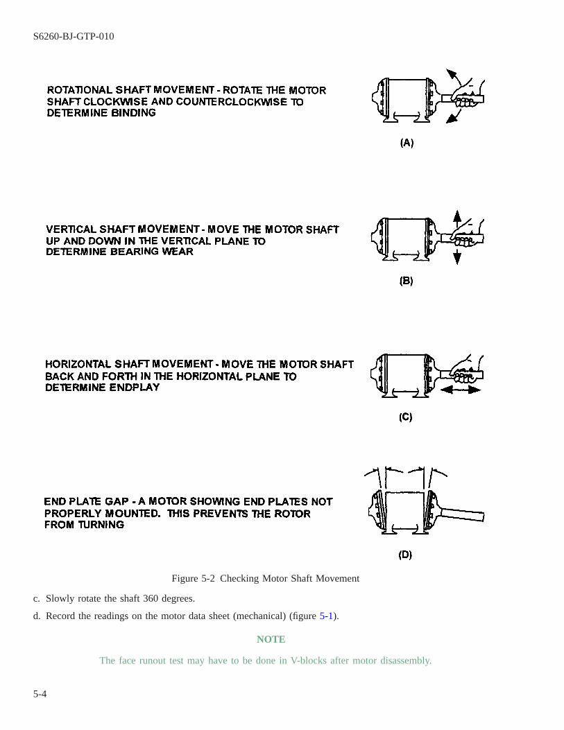
c. Slowly rotate the shaft 360 degrees.
d. Record the readings on the motor data sheet (mechanical) (figure 5-1).
NOTE
The face runout test may have to be done in V-blocks after motor disassembly.
Figure 5-2 Checking Motor Shaft Movement
S6260-BJ-GTP-010
5-4
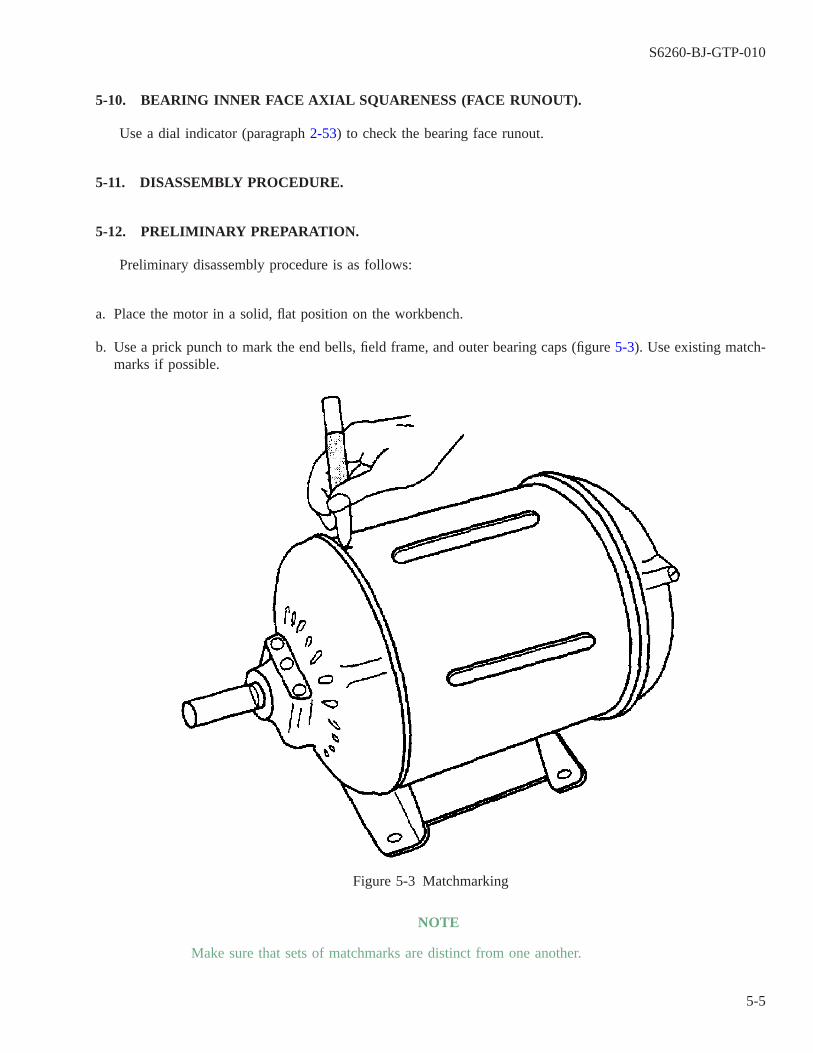
5-10. BEARING INNER FACE AXIAL SQUARENESS (FACE RUNOUT).
Use a dial indicator (paragraph 2-53) to check the bearing face runout.
5-11. DISASSEMBLY PROCEDURE.
5-12. PRELIMINARY PREPARATION.
Preliminary disassembly procedure is as follows:
a. Place the motor in a solid, flat position on the workbench.
b. Use a prick punch to mark the end bells, field frame, and outer bearing caps (figure 5-3). Use existing match-marks if possible.
NOTE
Make sure that sets of matchmarks are distinct from one another.
Figure 5-3 Matchmarking
S6260-BJ-GTP-010
5-5
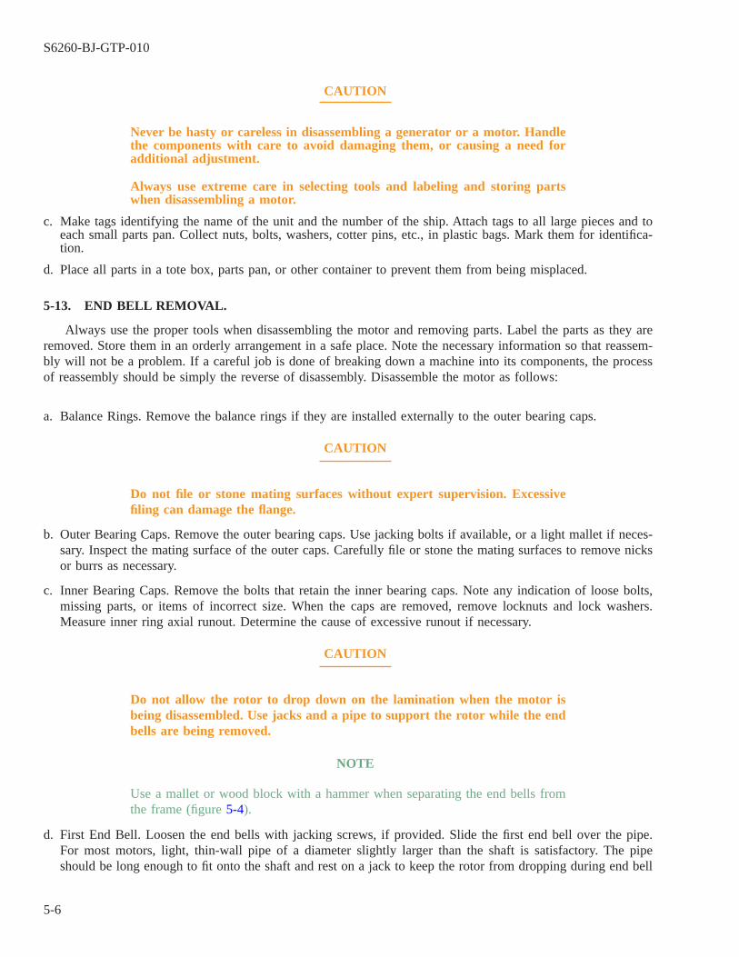
CAUTION
Never be hasty or careless in disassembling a generator or a motor. Handlethe components with care to avoid damaging them, or causing a need foradditional adjustment.
Always use extreme care in selecting tools and labeling and storing partswhen disassembling a motor.
c. Make tags identifying the name of the unit and the number of the ship. Attach tags to all large pieces and toeach small parts pan. Collect nuts, bolts, washers, cotter pins, etc., in plastic bags. Mark them for identifica-tion.
d. Place all parts in a tote box, parts pan, or other container to prevent them from being misplaced.
5-13. END BELL REMOVAL.
Always use the proper tools when disassembling the motor and removing parts. Label the parts as they areremoved. Store them in an orderly arrangement in a safe place. Note the necessary information so that reassem-bly will not be a problem. If a careful job is done of breaking down a machine into its components, the processof reassembly should be simply the reverse of disassembly. Disassemble the motor as follows:
a. Balance Rings. Remove the balance rings if they are installed externally to the outer bearing caps.
CAUTION
Do not file or stone mating surfaces without expert supervision. Excessivefiling can damage the flange.
b. Outer Bearing Caps. Remove the outer bearing caps. Use jacking bolts if available, or a light mallet if neces-sary. Inspect the mating surface of the outer caps. Carefully file or stone the mating surfaces to remove nicksor burrs as necessary.
c. Inner Bearing Caps. Remove the bolts that retain the inner bearing caps. Note any indication of loose bolts,missing parts, or items of incorrect size. When the caps are removed, remove locknuts and lock washers.Measure inner ring axial runout. Determine the cause of excessive runout if necessary.
CAUTION
Do not allow the rotor to drop down on the lamination when the motor isbeing disassembled. Use jacks and a pipe to support the rotor while the endbells are being removed.
NOTE
Use a mallet or wood block with a hammer when separating the end bells fromthe frame (figure 5-4).
d. First End Bell. Loosen the end bells with jacking screws, if provided. Slide the first end bell over the pipe.For most motors, light, thin-wall pipe of a diameter slightly larger than the shaft is satisfactory. The pipeshould be long enough to fit onto the shaft and rest on a jack to keep the rotor from dropping during end bell
S6260-BJ-GTP-010
5-6
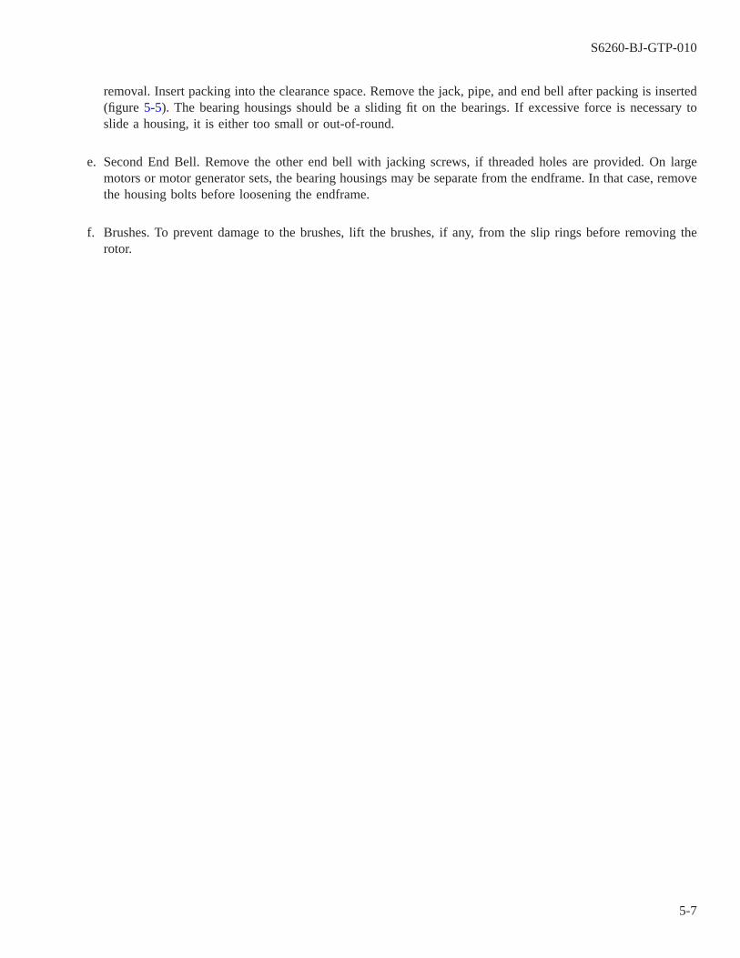
removal. Insert packing into the clearance space. Remove the jack, pipe, and end bell after packing is inserted(figure 5-5). The bearing housings should be a sliding fit on the bearings. If excessive force is necessary toslide a housing, it is either too small or out-of-round.
e. Second End Bell. Remove the other end bell with jacking screws, if threaded holes are provided. On largemotors or motor generator sets, the bearing housings may be separate from the endframe. In that case, removethe housing bolts before loosening the endframe.
f. Brushes. To prevent damage to the brushes, lift the brushes, if any, from the slip rings before removing therotor.
S6260-BJ-GTP-010
5-7
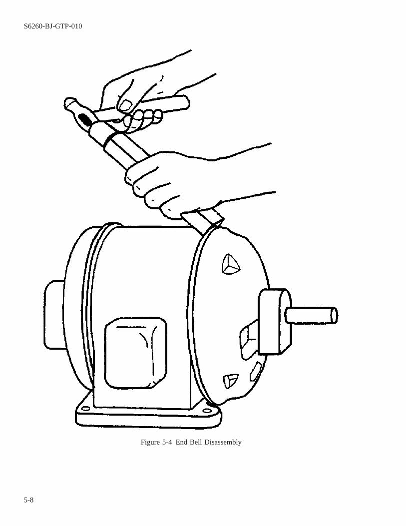
Figure 5-4 End Bell Disassembly
S6260-BJ-GTP-010
5-8
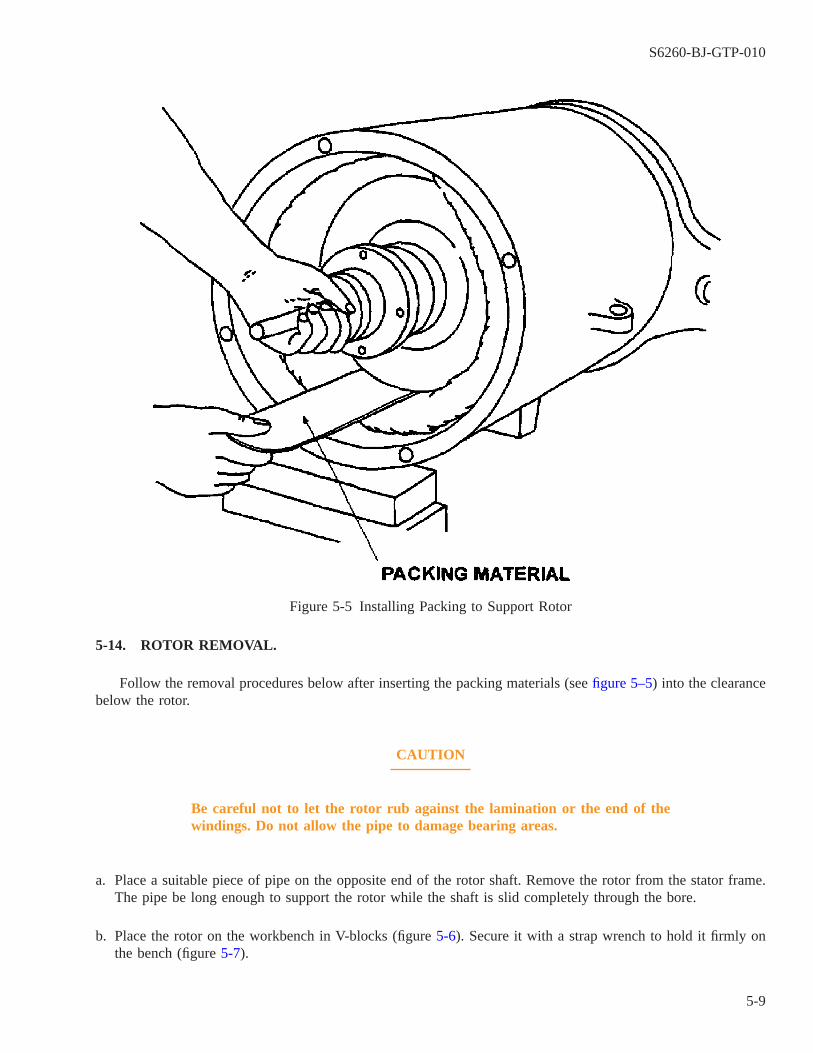
5-14. ROTOR REMOVAL.
Follow the removal procedures below after inserting the packing materials (see figure 5–5) into the clearancebelow the rotor.
CAUTION
Be careful not to let the rotor rub against the lamination or the end of thewindings. Do not allow the pipe to damage bearing areas.
a. Place a suitable piece of pipe on the opposite end of the rotor shaft. Remove the rotor from the stator frame.The pipe be long enough to support the rotor while the shaft is slid completely through the bore.
b. Place the rotor on the workbench in V-blocks (figure 5-6). Secure it with a strap wrench to hold it firmly onthe bench (figure 5-7).
Figure 5-5 Installing Packing to Support Rotor
S6260-BJ-GTP-010
5-9
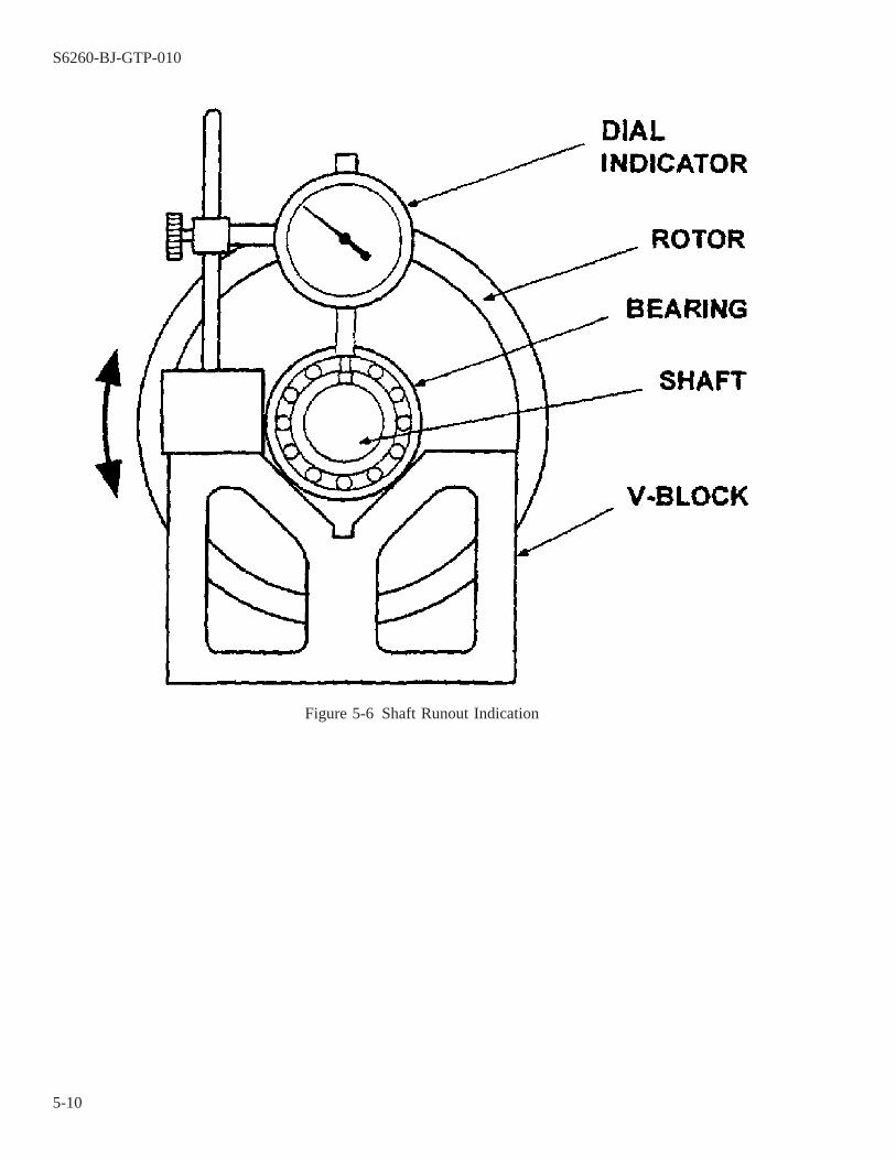
Figure 5-6 Shaft Runout Indication
S6260-BJ-GTP-010
5-10
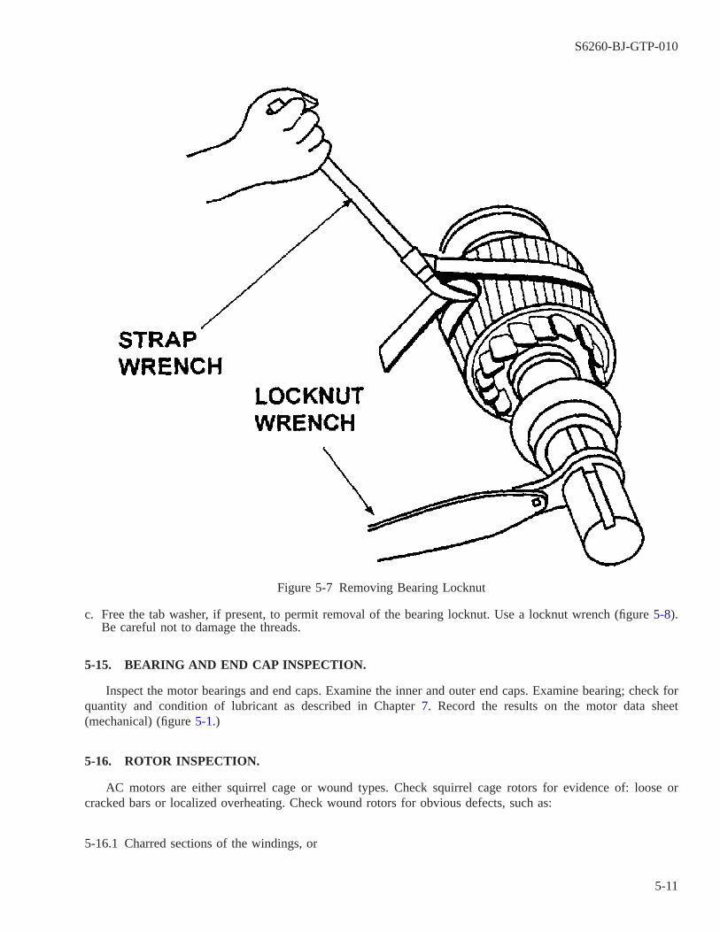
c. Free the tab washer, if present, to permit removal of the bearing locknut. Use a locknut wrench (figure 5-8).Be careful not to damage the threads.
5-15. BEARING AND END CAP INSPECTION.
Inspect the motor bearings and end caps. Examine the inner and outer end caps. Examine bearing; check forquantity and condition of lubricant as described in Chapter 7. Record the results on the motor data sheet(mechanical) (figure 5-1.)
5-16. ROTOR INSPECTION.
AC motors are either squirrel cage or wound types. Check squirrel cage rotors for evidence of: loose orcracked bars or localized overheating. Check wound rotors for obvious defects, such as:
5-16.1 Charred sections of the windings, or
Figure 5-7 Removing Bearing Locknut
S6260-BJ-GTP-010
5-11

5-16.2 Severe deterioration of the insulation, such as excessive cracking, flaking, or exposed bare copper.
5-17. ROTOR TEST.
Use a growler (paragraph 2-24) to test for loose bars in squirrel cage rotors which are not the die-cast type.
a. Place the rotor on the growler.
b. Hold a hacksaw blade over each bar.
NOTE
A loose bar causing an open circuit is indicated if a vibration is felt.
c. Reweld or resolder loose bars.
S6260-BJ-GTP-010
5-12
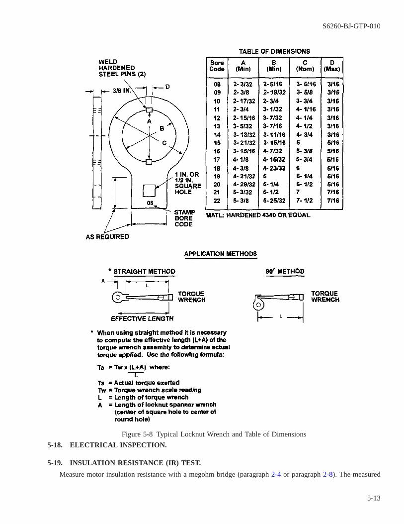
5-18. ELECTRICAL INSPECTION.
5-19. INSULATION RESISTANCE (IR) TEST.
Measure motor insulation resistance with a megohm bridge (paragraph 2-4 or paragraph 2-8). The measured
Figure 5-8 Typical Locknut Wrench and Table of Dimensions
S6260-BJ-GTP-010
5-13

value of IR should be temperature-corrected to 77° F (25° C) using the nomograph in figure 2-18. Refer to NSTMS9086-KC-STM-010/CH 300 for details on the use of the nomograph. The stator should be reconditioned asdescribed in Chapter 7 of this volume if the temperature-corrected value of the IR is below the ″Minimum ForOperation″ of table 7-2. Also see paragraph 5-20 for additional IR acceptance criteria. Record the results on themotor data sheet (electrical) (figure 5-9).
5-20. POLARIZATION INDEX (PI) TEST.
Used in conjunction with each other, the PI and the 1-minute value of IR are effective in identifying wind-ings that require reconditioning.
5-20.1 The winding must be reconditioned and, if necessary, rewound, if any of the following criteria are met:
5-20.1.1 The 1-minute IR is less than the ″Minimum For Operation″ in table 7-2.
5-20.1.2 The 1-minute IR is less than five times the ″After Reconditioning″ value (table 7-2) and the PI is unac-ceptable.
5-20.1.3 For motors with sealed insulation only, the 1-minute IR is less than 500 megohms and the PI is unac-ceptable.
5-20.2 In accordance with the above, perform a PI test if the temperature-corrected value of 1-minute IR isgreater than or equal to the ″Minimum For Operation″ and less than five times the applicable ″After Recondi-tioning″ value of table 7-2. Do not perform a PI test if the 1-minute IR is less than the ″Minimum For Opera-tion″ since the value of 1-minute IR preempts the PI from being a determining factor. Do not perform a PI testif the 1-minute IR is greater than or equal to five times the ″After Reconditioning″ value since the 1-minute IRpreempts the PI from being a determining factor. Perform the PI test using the procedures in paragraph 2-37.Record the results on the motor data sheet (electrical) (figure 5-9). Measured values of IR should be temperature-corrected to 77° F (25° C) using the nomograph in figure 2-18 before determining compliance with the minimumvalues in table 7-2. Refer to paragraph 2-37.2 for PI test acceptance criteria.
5-21. SURGE COMPARISON TEST.
Perform a surge comparison test (paragraph 2-19) on the winding to determine if there are shorted turns,coils, or windings. The stator must be rewound if internal short circuits or grounds are found. Proceed to the nextstep of testing if the winding is good. Record the results on the motor data sheet (electrical) (figure 5-9).
5-22. PHASE RESISTANCE BALANCE TEST.
Perform a phase resistance balance test (paragraph 2-15) to determine if the internal resistance of the phasesis within allowable limits. For motors over 3 horsepower (hp), the resistance of each phase must be within 5 per-cent of the others. The stator must be rewound if the difference between the high and low readings is greater than5 percent. Record results on the motor data sheet (electrical) (figure 5-9).
S6260-BJ-GTP-010
5-14

WARNING
Never conduct a high-potential test on a winding that has failed a groundinsulation test.
5-23. HIGH-POTENTIAL TEST.
Perform a dc high-potential test (paragraph 2-19 or paragraph 2-45) to determine cleanliness, and the mois-ture content and dielectric strength of the insulation.
5-24. CORE TEST.
Perform a core test (paragraph 2-38) to determine if there is deterioration of, or damage to, the core lamina-tion insulation (core plate) which can result in energy losses and overheating of the machine.
S6260-BJ-GTP-010
5-15

Figure 5-9 Motor Data Sheet (Electrical)
S6260-BJ-GTP-010
5-16
CHAPTER 6
MOTOR BEARINGS AND BEARING PROBLEMS
6-1. SCOPE.
This chapter contains information on motor bearings and the sources and causes of motor bearing failurecommonly experienced in electric motors. Complete bearing information for other applications is found inNAVSEA S9086-HN-STM-010/CH 244. Topics here include:
6-1.1 Types of motor bearings (paragraph 6-2).
6-1.2 Ball bearings (paragraph 6-4).
6-1.3 Bearing identification (paragraph 6-6).
6-1.4 Bearing design (paragraph 6-7).
6-1.5 Care of unmounted bearings (paragraph 6-9).
6-1.6 Safety precautions (paragraph 6-10).
6-1.7 Care of mounted bearings (paragraph 6-11).
6-1.8 Bearing replacement (paragraph 6-17).
6-1.9 Disassembly and bearing removal (paragraph 6-21).
6-1.10 Bearing installation and assembly (paragraph 6-25).
6-1.11 Special procedures for duplex bearings (paragraph 6-30).
6-1.12 Grease pack (paragraph 6-33).
6-1.13 Postrepair inspection (paragraph 6-37).
6-2. TYPES OF MOTOR BEARINGS.
6-3. BEARING DESIGNATIONS
Since most Navy motors use ball bearings , they will be discussed in detail in this chapter. Type designationsof ball bearings common to shipboard applications are described in table 6-1. Other types of bearings found inelectrical machinery are summarized in this paragraph. The principles of failure analysis, accuracy, and cleanworkmanship during replacement apply to all bearing systems. Final balancing and vibration measurements alsoapply to all systems. Other bearing types include:
6-3.1 Rolling-Element Bearings. Rolling-element bearings are used to guide and support rotating and oscillat-ing members. The rolling-element bearing, except for special designs, consists of two rings, a set of balls or roll-ers, and a cage. The cage maintains even spacing of the balls or rollers and prevents them from falling out of thebearing during handling. The rolling-element bearing has many uses in shipboard machine elements. Rolling-element bearing design is based on the principal that rolling friction is much less than sliding friction. Thesebearings are commonly called antifriction bearings. Reasonable changes in load, speed, and operating tempera-ture have no effect on their satisfactory performance.
S6260-BJ-GTP-010
6-1
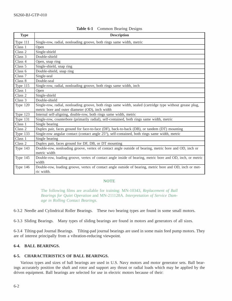
Table 6-1 Common Bearing Designs
Type Description
Type 111 Single-row, radial, nonloading groove, both rings same width, metricClass 1 OpenClass 2 Single-shieldClass 3 Double-shieldClass 4 Open, snap ringClass 5 Single-shield, snap ringClass 6 Double-shield, snap ringClass 7 Single-sealClass 8 Double-sealType 115 Single-row, radial, nonloading groove, both rings same width, inchClass 1 OpenClass 2 Single-shieldClass 3 Double-shieldType 120 Single-row, radial, nonloading groove, both rings same width, sealed (cartridge type without grease plug,
metric bore and outer diameter (OD), inch widthType 123 Internal self-aligning, double-row, both rings same width, metricType 131 Single-row, counterbore (primarily radial), self-contained, both rings same width, metricClass 1 Single bearingClass 2 Duplex pair, faces ground for face-to-face (DF), back-to-back (DB), or tandem (DT) mountingType 133 Single-row angular contact (contact angle 25°), self-contained, both rings same width, metricClass 1 Single bearingClass 2 Duplex pair, faces ground for DF, DB, or DT mountingType 143 Double-row, nonloading groove, vertex of contact angle outside of bearing, metric bore and OD, inch or
metric widthType 145 Double-row, loading groove, vertex of contact angle inside of bearing, metric bore and OD, inch, or metric
widthType 146 Double-row, loading groove, vertex of contact angle outside of bearing, metric bore and OD, inch or met-
ric width.
NOTE
The following films are available for training: MN-10343, Replacement of BallBearings for Quiet Operation and MN-211128A. Interpretation of Service Dam-age in Rolling Contact Bearings.
6-3.2 Needle and Cylindrical Roller Bearings. These two bearing types are found in some small motors.
6-3.3 Sliding Bearings. Many types of sliding bearings are found in motors and generators of all sizes.
6-3.4 Tilting-pad Journal Bearings. Tilting-pad journal bearings are used in some main feed pump motors. Theyare of interest principally from a vibration-reducing viewpoint.
6-4. BALL BEARINGS.
6-5. CHARACTERISTICS OF BALL BEARINGS.
Various types and sizes of ball bearings are used in U.S. Navy motors and motor generator sets. Ball bear-ings accurately position the shaft and rotor and support any thrust or radial loads which may be applied by thedriven equipment. Ball bearings are selected for use in electric motors because of their:
S6260-BJ-GTP-010
6-2

6-5.1 Small size and low weight, with high load capacity.
6-5.2 Very small internal clearance, which permits accurate balancing of rotors.
6-5.3 Long operating lives.
6-5.4 Very low lubrication requirements.
6-5.5 Small radial clearance.
6-5.6 Mass production to standard dimensions, with extremely high and uniform quality.
6-5.7 Precision. Three grades of precision are available. The standard grade of precision is grade 00 standardtolerance. This level is satisfactory for most designs and, therefore, has the widest use. Bearings having closertolerances on dimensions are manufactured to grade 50 precision tolerances or grade 70 super-precision toler-ances. Most ball bearings are purchased in accordance with FF-B-171, Bearings, Ball, Annular (General Pur-pose) . Ball bearings for Navy noise-critical applications are purchased under a special Naval Sea Systems Com-mand (NAVSEA) specification, MIL-B-17931, Bearings, Ball, Annular For Quiet Operation. Dimensionaltolerances for these bearings are similar to grade 50 and 70 limits. Additional strict requirements are imposed onthese bearings to ensure a minimum of bearing noise and vibration. Such bearings are marked with the symbolNT followed by the number designated to the latest noise requirement in MIL-B-17931 and will be referred tothroughout this manual as quiet bearings.
6-5.8 Limitations. Except as directed in paragraph 6-39 or as specified or approved by NAVSEA, ball bearingsfor shipboard use are limited to the grade, type, and class specified for the original equipment. Quiet bearings arenot intended for general use and are restricted to low-noise applications.
6-6. BEARING IDENTIFICATION.
6-6.1 National Stock Numbers (NSN). In the National Supply System, rolling-element bearings are identifiedby National Stock Numbers (NSN). Each bearing NSN has an item description that lists the bearing design fea-tures peculiar to that NSN. This item description is used to procure new bearings from government-qualifiedmanufacturers, ensuring interchangeability. All bearings should have the NSN marked on the outer unit package.
6-6.2 Allowance Part List (APL). In support of the National Supply System, NAVSEA has established theCoordinated Ship Allowance List (COSAL) and the Allowance Parts List (APL). The COSAL identifies specificequipment by the Component Identification Number (CID), usually the first five numbers of the APL number forhull, mechanical, and electrical (HM&E) APLs. The APL is a ready reference that lists onboard replacement partsby name and NSN for specific equipment as identified by the CIDs. Bearing NSNs should always appear on theAPL as onboard replacement items. Procurement request shall specify the NSN.
6-6.3 Bearing Type. The bearing types listed in table 6-1 are in accordance with MIL-STD-102, Anti-FrictionBearing Identification Code . The code is descriptive and consists of 12 digits broken down into three groups.The first three digits classify the bearing type. The next five digits code the principal boundary dimensions ofbore, outside diameter (OD), and width. The last four digits code variations such as precision, internal clearance,
S6260-BJ-GTP-010
6-3
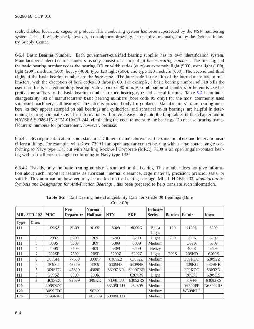
seals, shields, lubricant, cages, or preload. This numbering system has been superseded by the NSN numberingsystem. It is still widely used, however, on equipment drawings, in technical manuals, and by the Defense Indus-try Supply Center.
6-6.4 Basic Bearing Number. Each government-qualified bearing supplier has its own identification system.Manufacturers’ identification numbers usually consist of a three-digit basic bearing number . The first digit ofthe basic bearing number codes the bearing OD or width series (duty) as extremely light (900), extra light (100),light (200), medium (300), heavy (400), type 120 light (500), and type 120 medium (600). The second and thirddigits of the basic bearing number are the bore code . The bore code is one-fifth of the bore dimensions in mil-limeters, with the exception of bore codes 00 through 03. For example, a basic bearing number of 318 tells theuser that this is a medium duty bearing with a bore of 90 mm. A combination of numbers or letters is used asprefixes or suffixes to the basic bearing number to code bearing type and special features. Table 6-2 is an inter-changeability list of manufacturers’ basic bearing numbers (bore code 09 only) for the most commonly usedshipboard machinery ball bearings. The table is provided only for guidance. Manufacturers’ basic bearing num-bers, as they appear stamped on ball bearings and cylindrical and spherical roller bearings, are helpful in deter-mining bearing nominal size. This information will provide easy entry into the fitup tables in this chapter and inNAVSEA S9086-HN-STM-010/CR 244, eliminating the need to measure the bearings. Do not use bearing manu-facturers’ numbers for procurement, however, because:
6-6.4.1 Bearing identification is not standard. Different manufacturers use the same numbers and letters to meandifferent things. For example, with Koyo 7309 in an open angular-contact bearing with a large contact angle con-forming to Navy type 134, but with Marling Rockwell Corporate (MRC), 7309 is an open angular-contact bear-ing with a small contact angle conforming to Navy type 133.
6-6.4.2 Usually, only the basic bearing number is stamped on the bearing. This number does not give informa-tion about such important features as lubricant, internal clearance, cage material, precision, preload, seals, orshields. This information, however, may be marked on the bearing package. MIL-L-HDBK-203, Manufacturers’Symbols and Designation for Anti-Friction Bearings , has been prepared to help translate such information.
Table 6-2 Ball Bearing Interchangeability Data for Grade 00 Bearings (BoreCode 09)
MIL-STD-102 MRCNewDeparture
Norma-Hoffman NTN SKF
IndustrySeries Barden Fafnir Koyo
Type Class111 1 109KS 3L09 6109 6009 6009X Extra
Light109 9109K 6009
111 1 2092 3209 209 6209 6209 Light 209 209K 6209111 1 309S 3309 309 6309 6309 Medium 309K 6309111 1 409S 3409 409 6409 6409 Heavy 409K 6409111 2 209SF 7509 209P 6209Z 6209Z Light 209S 209KD 6209Z111 3 309SFF 77609 309PP 6309ZZ 63092Z Medium 309KDD 6309ZZ111 4 309SG 43309 4309 6309NR 6309NR Medium 309KG 6309NR111 5 309SFG 47609 4309P 6309ZNR 6309ZNR Medium 309KDG 6309ZN111 7 209SZ 9509 209K 6209RS Light 209KP 6209RS111 8 309SZZ 99609 309KK 6309LLU 63092RS Medium 309FF 63092RS120 309SZZC 63309LLU 462309 Medium W309PP N63092RS120 309SFFC S6309 Medium W309KLL120 309SRRC FL3609 63309LLB Medium
S6260-BJ-GTP-010
6-4
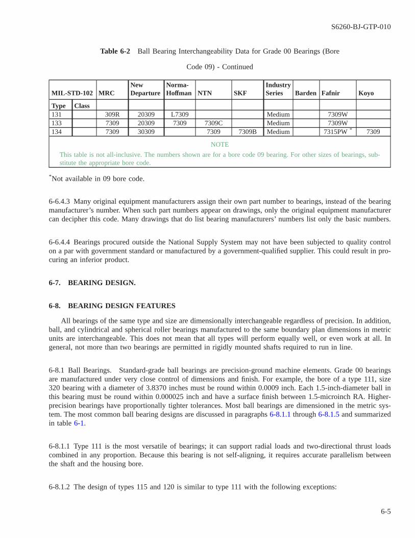
Table 6-2 Ball Bearing Interchangeability Data for Grade 00 Bearings (Bore
Code 09) - Continued
MIL-STD-102 MRCNewDeparture
Norma-Hoffman NTN SKF
IndustrySeries Barden Fafnir Koyo
Type Class131 309R 20309 L7309 Medium 7309W133 7309 20309 7309 7309C Medium 7309W134 7309 30309 7309 7309B Medium 7315PW * 7309
NOTE
This table is not all-inclusive. The numbers shown are for a bore code 09 bearing. For other sizes of bearings, sub-stitute the appropriate bore code.
*Not available in 09 bore code.
6-6.4.3 Many original equipment manufacturers assign their own part number to bearings, instead of the bearingmanufacturer’s number. When such part numbers appear on drawings, only the original equipment manufacturercan decipher this code. Many drawings that do list bearing manufacturers’ numbers list only the basic numbers.
6-6.4.4 Bearings procured outside the National Supply System may not have been subjected to quality controlon a par with government standard or manufactured by a government-qualified supplier. This could result in pro-curing an inferior product.
6-7. BEARING DESIGN.
6-8. BEARING DESIGN FEATURES
All bearings of the same type and size are dimensionally interchangeable regardless of precision. In addition,ball, and cylindrical and spherical roller bearings manufactured to the same boundary plan dimensions in metricunits are interchangeable. This does not mean that all types will perform equally well, or even work at all. Ingeneral, not more than two bearings are permitted in rigidly mounted shafts required to run in line.
6-8.1 Ball Bearings. Standard-grade ball bearings are precision-ground machine elements. Grade 00 bearingsare manufactured under very close control of dimensions and finish. For example, the bore of a type 111, size320 bearing with a diameter of 3.8370 inches must be round within 0.0009 inch. Each 1.5-inch-diameter ball inthis bearing must be round within 0.000025 inch and have a surface finish between 1.5-microinch RA. Higher-precision bearings have proportionally tighter tolerances. Most ball bearings are dimensioned in the metric sys-tem. The most common ball bearing designs are discussed in paragraphs 6-8.1.1 through 6-8.1.5 and summarizedin table 6-1.
6-8.1.1 Type 111 is the most versatile of bearings; it can support radial loads and two-directional thrust loadscombined in any proportion. Because this bearing is not self-aligning, it requires accurate parallelism betweenthe shaft and the housing bore.
6-8.1.2 The design of types 115 and 120 is similar to type 111 with the following exceptions:
S6260-BJ-GTP-010
6-5

6-8.1.2.1 Type 115 is dimensioned in inches.
6-8.1.2.2 Type 120 is termed a cartridge bearing since it is as wide as a double-row bearing but has only onerow of balls. Type 120 bearings are double sealed or double shielded and lubricated for life by the bearing manu-facturer.
6-8.1.3 Type 123 bearings are used mainly where housing alignment is uncertain. They will support moderateradial loads and light two-directional thrust loads. They are internally self-aligning.
6-8.1.4 Types 131, 133, and 134 are angular-contact ball bearings designed to support thrust loads in one direc-tion, possibly in combination with radial loads.
6-8.1.4.1 In all three types, the direction of load through the balls forms an angle (the contact angle ) with aplane perpendicular to the bearing axis. The thrust capacity increases with increasing contact angle. These bear-ings usually have a greater number of balls than type 111 bearings. Type 134 has a range of contact angles largerthan type 133, which in turn has a range of contact angles larger than type 131.
6-8.1.4.2 Angular contact bearings are frequently made so that they can be mounted in pairs (back-to-back (DB),tandem, or face-to-face (DF)). This enables them to carry radial, thrust, or combined loads in any direction (fig-ure 6-1b). These arrangements are called duplex pairs . In these arrangements bearing ring side surfaces areground so that when the assembled bearings are clamped together, the desired internal clearance, or preload , isobtained. For general purpose applications duplex pairs are designed as flush-ground bearings. This means theywill not have a significant preload or measurable end play. For specialized applications, varying degrees of pre-load, or end play, may be desired. In these cases, the bearing ring sides surfaces are ground to give the desiredload condition.
S6260-BJ-GTP-010
6-6
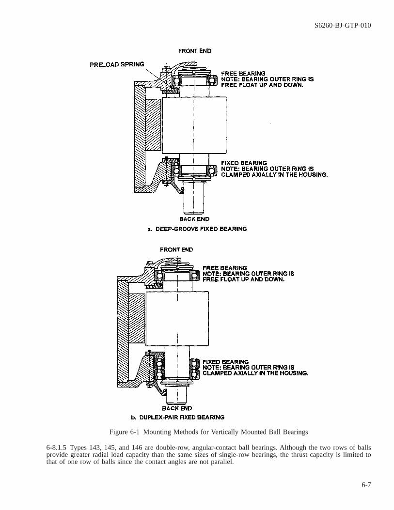
6-8.1.5 Types 143, 145, and 146 are double-row, angular-contact ball bearings. Although the two rows of ballsprovide greater radial load capacity than the same sizes of single-row bearings, the thrust capacity is limited tothat of one row of balls since the contact angles are not parallel.
Figure 6-1 Mounting Methods for Vertically Mounted Ball Bearings
S6260-BJ-GTP-010
6-7
6-8.2 Bearing Cages. Cages are made to many different designs and of several different materials. The cageseparates the rolling elements, spacing them evenly around the periphery and preventing them from falling outof the bearing during handling. In addition, in some roller bearing designs, the cage guides the rollers, prevent-ing them from skewing. The cage is not designed to help carry the load. It can be subjected, however, to con-siderable inertial forces due to acceleration, shock due to extreme service, and centrifugal force due to high speed.Cages are either machined or stamped, usually from steel, brass, bronze, phenolic, or plastic material. The cagemay pilot or ride on the balls, rollers, inner ring lands, or outer ring lands. In general shipboard applications, allcage types perform equally well. Standard cage materials of brass, bronze, phenolic, and plastic are restricted tooperational temperatures below 230° F (110° C).
6-8.3 Seals and Shields. Seals and shields integral to the bearing are incorporated to prevent the entry of for-eign matter and to retain lubricant. Shields are usually defined as circular closures affixed to one bearing ring anddisposed radially toward the other ring but not in contact with it. Seals are similarly defined except they haverubbing contact lips or overlapping elements that form a labyrinth. It may not be outwardly possible to distin-guish between a seal or shields as mounted in the bearing. Use of seals and shields has not been standardized bythe bearing industry. Since many designs are available, it has been necessary to group the types that functionsimilarly. Rubbing contact seals generate heat and so are limited by bearing size and rotational speed. In addi-tion, all standard seal materials made of rubber, felt, or leather cannot be used at temperatures above 230° F (110°C).
6-8.4 Radial Internal Clearance. Radial internal clearance is the distance the inner ring can be displaced radi-ally from one extreme position to the other in relation to the outer ring. Bearings of type 111, 115, 120, 211,212,213, 215, 231, 232, 233, 237, 264, 764, 765, 767, and 768 are available with standard radial internal clearances.For unlisted bearing types, the internal clearances are either determined by adjustment or fitted to the manufac-turer’s standard practice.
6-8.4.1 Shipboard applications generally use bearings with standard clearance. Under ordinary operating condi-tions and with one bearing ring mounted with an interference fit, this clearance is adequate. When sealed bear-ings are used, a loose clearance is required. When severe operating conditions require an extra tight fit for theinterference-fitted ring, when both rings must be mounted with a press fit, or when thermal expansion of the innerring is considerably more than the outer ring, a loose clearance may be required. The degree of bearing internalclearance necessary is generally specified by the original equipment manufacturer and, if it is other than stan-dard, this is indicated on the equipment master drawing.
6-8.4.2 Type 111 and 120 quiet ball bearings have stricter limits on radial internal clearance than those standard-ized by the bearing industry.
6-8.4.3 Separable-type bearings that are nonadjustable must be installed as originally matched by the manufac-turer to maintain the required radial internal clearance. Mismatching these types will usually result in prematurefailure.
S6260-BJ-GTP-010
6-8
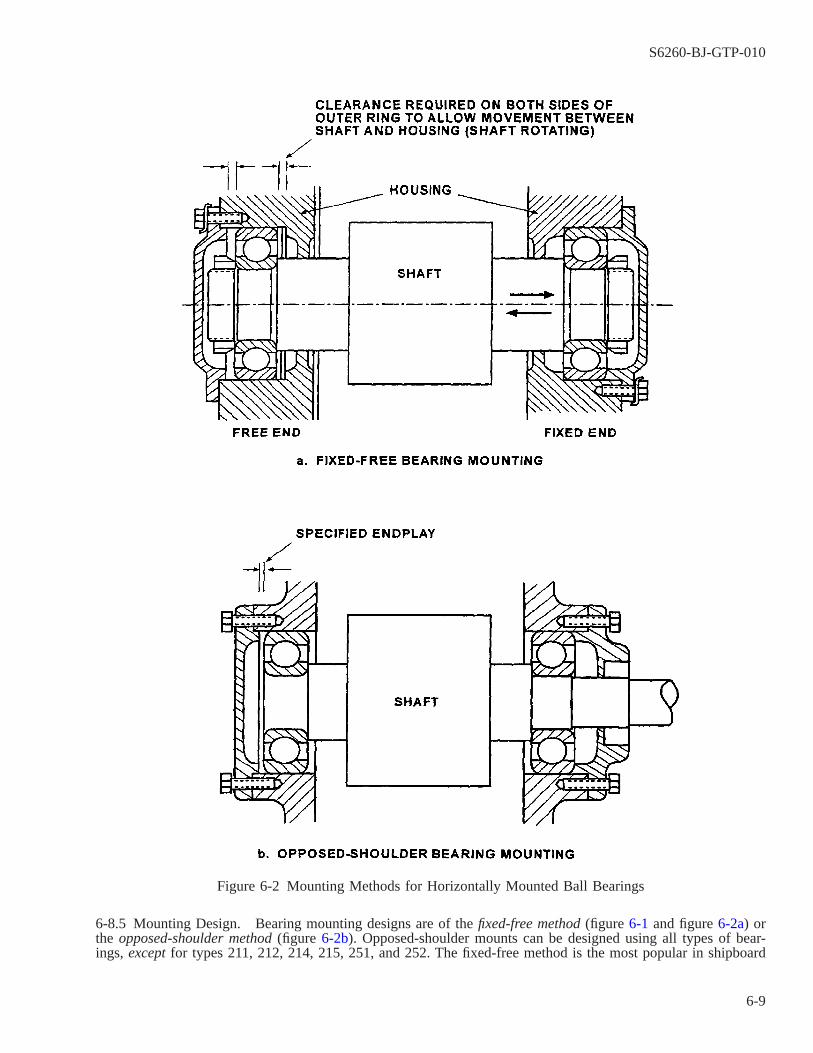
6-8.5 Mounting Design. Bearing mounting designs are of the fixed-free method (figure 6-1 and figure 6-2a) orthe opposed-shoulder method (figure 6-2b). Opposed-shoulder mounts can be designed using all types of bear-ings, except for types 211, 212, 214, 215, 251, and 252. The fixed-free method is the most popular in shipboard
Figure 6-2 Mounting Methods for Horizontally Mounted Ball Bearings
S6260-BJ-GTP-010
6-9

applications. The fixed bearing is secured on the shaft and clamped axially in the housing by end caps. The fixedbearing must be suitable for supporting radial loads and two-directional thrust loads. The floating bearings can beof any type as long as design requirements are satisfied. If the floating bearing is a cylindrical roller bearing oftype 212, 214, 215, 251, or 252, the outer rings will be clamped axially and the bearing will float internally. Ifany other type of bearing is used, one ring will be clamped axially and the other will float. For rotating shafts,the inner ring will be clamped axially to the shaft, requiring that the outer ring have room to move axially in thehousing. The clearance required depends on the bearing span, the machining tolerances affecting the span, andthe shaft-to-housing temperature difference expected in service. When a bearing capable of only one-directionalthrust is used as the floating bearing, thrust load output from dead weight, axial spring preload, or other loadingmust always be present to keep the bearing from separating. For duplex pairs, the back-to-back (DB) pair can beallowed to float in the housing. However, the face-to-face (DF) pair cannot be allowed to float in the housing,since the nonthrusted outer ring will separate from the bearing. These duplex pairs shall be installed as originallydesigned.
6-8.6 Shaft and Housing Design. Rolling-element bearing bores and outside diameters are held within certaindefined tolerances, depending on bearing precision grade. In turn, shaft and housing diameters must be held tocomparable limits also in accordance with bearing precision grade. Limits and fits are ordinarily determined bythe fits best suited for the application. The shaft and housing fitups in this chapter and NAVSEA S9086-HN-STM-010/CH 244 are for use where dynamic conditions are indicated, which are characteristic of most naval shipboardapplications. Shaft and housing seats and shoulder surfaces should be ground. The machining tolerances speci-fied in table 6-3 through table 6-5 are the minimum requirements for reliable bearing life. Use these limits whenother information is unavailable or when such other limits exceed the limits herein.
Table 6-3 Shaft Diameter Limits for Grade 00 and Quiet BearingsShaft Diameter Limits 2 (inches)
Bearing Bore Shaft Rotating Shaft Stationary 1
Nominal Ball Quiet Cylindrical SphericalBoreCode MM Inch Max. Min. Max. Min. Max. Min. Max. Min. Max. Min.
4 4 0.1575 0.1576 0.1574 0.1573 0.15705 5 1.1969 0.1970 0.1968 0.1967 0.19646 6 0.2362 0.2363 0.2361 0.2360 0.23577 7 0.2756 0.2758 0.2755 0.2754 0.27508 8 0.3150 0.3152 0.3149 0.3148 0.31449 9 0.3543 0.3545 0.3542 0.3541 0.353700 10 0.3937 0.3939 0.3936 0.3940 0.3938 0.3935 0.393101 12 0.4724 0.4726 0.4723 0.4727 0.4725 0.4728 0.4723 0.4721 0.471702 15 0.5906 0.5908 0.5905 0.5909 0.5907 0.5910 0.5907 0.5903 0.589903 17 0.6693 0.6695 0.6692 0.6696 0.6696 0.6697 0.6694 0.6690 0.668604 20 0.7874 0.7879 0.7875 0.7877 0.7877 0.7879 0.7875 0.7871 0.786605 25 0.9843 0.9848 0.9844 0.9846 0.9846 0.9848 0.9844 0.9840 0.983506 30 1.1811 1.1816 1.1812 1.1814 1.1812 1.1816 1.1812 1.1808 1.180307 35 1.3780 1.3785 1.3781 1.3783 1.3781 1.3785 1.3781 1.3776 1.377008 40 1.5748 1.5753 1.5749 1.5751 1.5749 1.5753 1.5749 1.5753 1.5749 1.5744 1.573809 45 1.7717 1.7722 1.7718 1.7720 1.7718 1.7725 1.7721 1.7725 1.7721 1.7713 1.770710 50 1.9685 1.9690 1.9686 1.9688 1.9686 1.9693 1.9689 1.9693 1.9689 1.9681 1.967511 55 2.1654 2.1660 2.1655 2.1657 2.1655 2.1664 2.1659 2.1664 2.1659 2.1650 2.164312 60 2.3622 2.3628 2.3623 2.325 2.3623 2.3632 2.3627 2.3632 2.3526 2.3618 2.361113 65 2.5591 2.5597 2.5592 2.5594 2.5592 2.5601 2.5596 2.5601 2.5596 2.5587 2.558014 70 2.7559 2.7565 2.7560 2.7562 2.7560 2.7569 2.7564 2.7571 2.7564 2.7555 2.754815 75 2.9528 2.9534 2.9529 2.9531 2.9529 2.9538 2.9533 2.9540 2.9533 2.9524 2.951716 80 3.1496 3.1502 3.1497 3.1500 3.1497 3.1506 3.1501 3.1508 3.1501 3.1492 3.1485
S6260-BJ-GTP-010
6-10
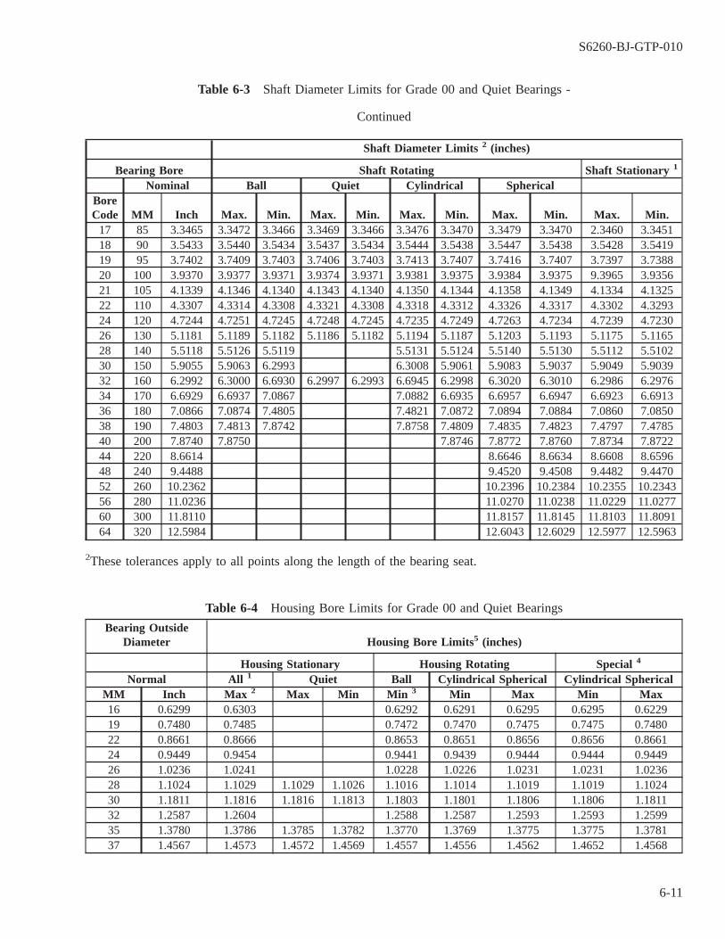
Table 6-3 Shaft Diameter Limits for Grade 00 and Quiet Bearings -
Continued
Shaft Diameter Limits 2 (inches)
Bearing Bore Shaft Rotating Shaft Stationary 1
Nominal Ball Quiet Cylindrical SphericalBoreCode MM Inch Max. Min. Max. Min. Max. Min. Max. Min. Max. Min.
17 85 3.3465 3.3472 3.3466 3.3469 3.3466 3.3476 3.3470 3.3479 3.3470 2.3460 3.345118 90 3.5433 3.5440 3.5434 3.5437 3.5434 3.5444 3.5438 3.5447 3.5438 3.5428 3.541919 95 3.7402 3.7409 3.7403 3.7406 3.7403 3.7413 3.7407 3.7416 3.7407 3.7397 3.738820 100 3.9370 3.9377 3.9371 3.9374 3.9371 3.9381 3.9375 3.9384 3.9375 9.3965 3.935621 105 4.1339 4.1346 4.1340 4.1343 4.1340 4.1350 4.1344 4.1358 4.1349 4.1334 4.132522 110 4.3307 4.3314 4.3308 4.3321 4.3308 4.3318 4.3312 4.3326 4.3317 4.3302 4.329324 120 4.7244 4.7251 4.7245 4.7248 4.7245 4.7235 4.7249 4.7263 4.7234 4.7239 4.723026 130 5.1181 5.1189 5.1182 5.1186 5.1182 5.1194 5.1187 5.1203 5.1193 5.1175 5.116528 140 5.5118 5.5126 5.5119 5.5131 5.5124 5.5140 5.5130 5.5112 5.510230 150 5.9055 5.9063 6.2993 6.3008 5.9061 5.9083 5.9037 5.9049 5.903932 160 6.2992 6.3000 6.6930 6.2997 6.2993 6.6945 6.2998 6.3020 6.3010 6.2986 6.297634 170 6.6929 6.6937 7.0867 7.0882 6.6935 6.6957 6.6947 6.6923 6.691336 180 7.0866 7.0874 7.4805 7.4821 7.0872 7.0894 7.0884 7.0860 7.085038 190 7.4803 7.4813 7.8742 7.8758 7.4809 7.4835 7.4823 7.4797 7.478540 200 7.8740 7.8750 7.8746 7.8772 7.8760 7.8734 7.872244 220 8.6614 8.6646 8.6634 8.6608 8.659648 240 9.4488 9.4520 9.4508 9.4482 9.447052 260 10.2362 10.2396 10.2384 10.2355 10.234356 280 11.0236 11.0270 11.0238 11.0229 11.027760 300 11.8110 11.8157 11.8145 11.8103 11.809164 320 12.5984 12.6043 12.6029 12.5977 12.5963
2These tolerances apply to all points along the length of the bearing seat.
Table 6-4 Housing Bore Limits for Grade 00 and Quiet Bearings
Bearing OutsideDiameter Housing Bore Limits5 (inches)
Housing Stationary Housing Rotating Special 4
Normal All 1 Quiet Ball Cylindrical Spherical Cylindrical SphericalMM Inch Max 2 Max Min Min 3 Min Max Min Max16 0.6299 0.6303 0.6292 0.6291 0.6295 0.6295 0.622919 0.7480 0.7485 0.7472 0.7470 0.7475 0.7475 0.748022 0.8661 0.8666 0.8653 0.8651 0.8656 0.8656 0.866124 0.9449 0.9454 0.9441 0.9439 0.9444 0.9444 0.944926 1.0236 1.0241 1.0228 1.0226 1.0231 1.0231 1.023628 1.1024 1.1029 1.1029 1.1026 1.1016 1.1014 1.1019 1.1019 1.102430 1.1811 1.1816 1.1816 1.1813 1.1803 1.1801 1.1806 1.1806 1.181132 1.2587 1.2604 1.2588 1.2587 1.2593 1.2593 1.259935 1.3780 1.3786 1.3785 1.3782 1.3770 1.3769 1.3775 1.3775 1.378137 1.4567 1.4573 1.4572 1.4569 1.4557 1.4556 1.4562 1.4652 1.4568
S6260-BJ-GTP-010
6-11
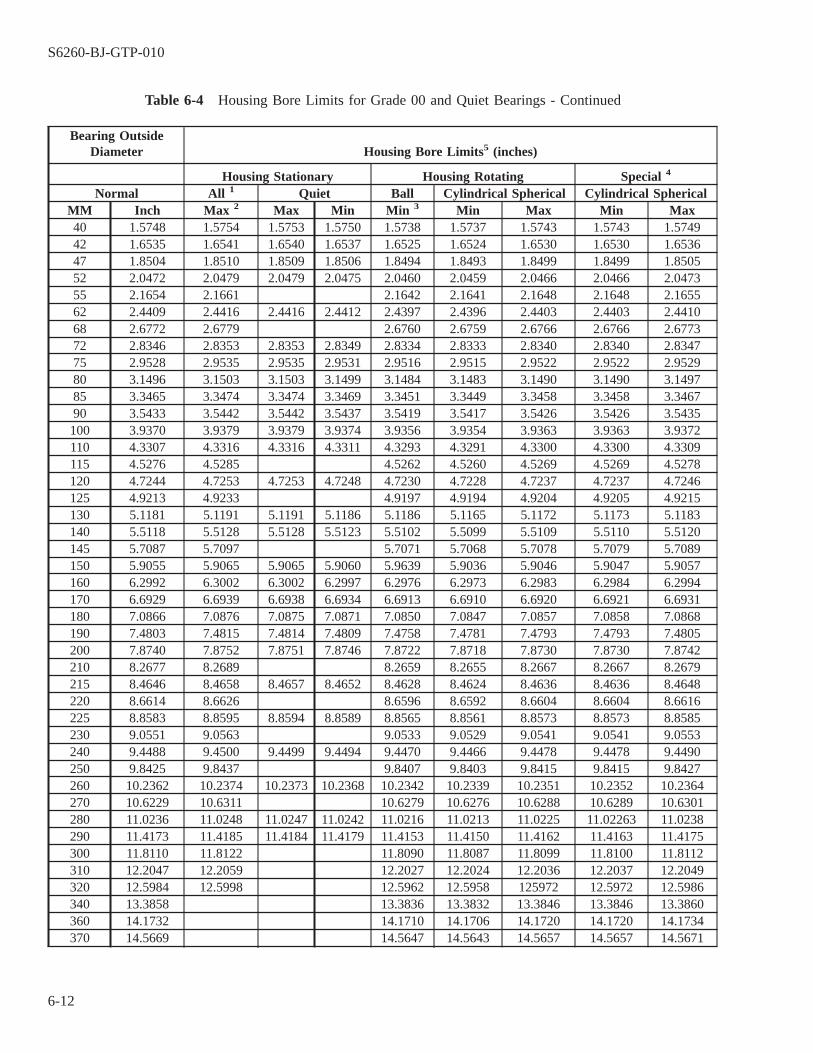
Table 6-4 Housing Bore Limits for Grade 00 and Quiet Bearings - Continued
Bearing OutsideDiameter Housing Bore Limits5 (inches)
Housing Stationary Housing Rotating Special 4
Normal All 1 Quiet Ball Cylindrical Spherical Cylindrical SphericalMM Inch Max 2 Max Min Min 3 Min Max Min Max40 1.5748 1.5754 1.5753 1.5750 1.5738 1.5737 1.5743 1.5743 1.574942 1.6535 1.6541 1.6540 1.6537 1.6525 1.6524 1.6530 1.6530 1.653647 1.8504 1.8510 1.8509 1.8506 1.8494 1.8493 1.8499 1.8499 1.850552 2.0472 2.0479 2.0479 2.0475 2.0460 2.0459 2.0466 2.0466 2.047355 2.1654 2.1661 2.1642 2.1641 2.1648 2.1648 2.165562 2.4409 2.4416 2.4416 2.4412 2.4397 2.4396 2.4403 2.4403 2.441068 2.6772 2.6779 2.6760 2.6759 2.6766 2.6766 2.677372 2.8346 2.8353 2.8353 2.8349 2.8334 2.8333 2.8340 2.8340 2.834775 2.9528 2.9535 2.9535 2.9531 2.9516 2.9515 2.9522 2.9522 2.952980 3.1496 3.1503 3.1503 3.1499 3.1484 3.1483 3.1490 3.1490 3.149785 3.3465 3.3474 3.3474 3.3469 3.3451 3.3449 3.3458 3.3458 3.346790 3.5433 3.5442 3.5442 3.5437 3.5419 3.5417 3.5426 3.5426 3.5435100 3.9370 3.9379 3.9379 3.9374 3.9356 3.9354 3.9363 3.9363 3.9372110 4.3307 4.3316 4.3316 4.3311 4.3293 4.3291 4.3300 4.3300 4.3309115 4.5276 4.5285 4.5262 4.5260 4.5269 4.5269 4.5278120 4.7244 4.7253 4.7253 4.7248 4.7230 4.7228 4.7237 4.7237 4.7246125 4.9213 4.9233 4.9197 4.9194 4.9204 4.9205 4.9215130 5.1181 5.1191 5.1191 5.1186 5.1186 5.1165 5.1172 5.1173 5.1183140 5.5118 5.5128 5.5128 5.5123 5.5102 5.5099 5.5109 5.5110 5.5120145 5.7087 5.7097 5.7071 5.7068 5.7078 5.7079 5.7089150 5.9055 5.9065 5.9065 5.9060 5.9639 5.9036 5.9046 5.9047 5.9057160 6.2992 6.3002 6.3002 6.2997 6.2976 6.2973 6.2983 6.2984 6.2994170 6.6929 6.6939 6.6938 6.6934 6.6913 6.6910 6.6920 6.6921 6.6931180 7.0866 7.0876 7.0875 7.0871 7.0850 7.0847 7.0857 7.0858 7.0868190 7.4803 7.4815 7.4814 7.4809 7.4758 7.4781 7.4793 7.4793 7.4805200 7.8740 7.8752 7.8751 7.8746 7.8722 7.8718 7.8730 7.8730 7.8742210 8.2677 8.2689 8.2659 8.2655 8.2667 8.2667 8.2679215 8.4646 8.4658 8.4657 8.4652 8.4628 8.4624 8.4636 8.4636 8.4648220 8.6614 8.6626 8.6596 8.6592 8.6604 8.6604 8.6616225 8.8583 8.8595 8.8594 8.8589 8.8565 8.8561 8.8573 8.8573 8.8585230 9.0551 9.0563 9.0533 9.0529 9.0541 9.0541 9.0553240 9.4488 9.4500 9.4499 9.4494 9.4470 9.4466 9.4478 9.4478 9.4490250 9.8425 9.8437 9.8407 9.8403 9.8415 9.8415 9.8427260 10.2362 10.2374 10.2373 10.2368 10.2342 10.2339 10.2351 10.2352 10.2364270 10.6229 10.6311 10.6279 10.6276 10.6288 10.6289 10.6301280 11.0236 11.0248 11.0247 11.0242 11.0216 11.0213 11.0225 11.02263 11.0238290 11.4173 11.4185 11.4184 11.4179 11.4153 11.4150 11.4162 11.4163 11.4175300 11.8110 11.8122 11.8090 11.8087 11.8099 11.8100 11.8112310 12.2047 12.2059 12.2027 12.2024 12.2036 12.2037 12.2049320 12.5984 12.5998 12.5962 12.5958 125972 12.5972 12.5986340 13.3858 13.3836 13.3832 13.3846 13.3846 13.3860360 14.1732 14.1710 14.1706 14.1720 14.1720 14.1734370 14.5669 14.5647 14.5643 14.5657 14.5657 14.5671
S6260-BJ-GTP-010
6-12
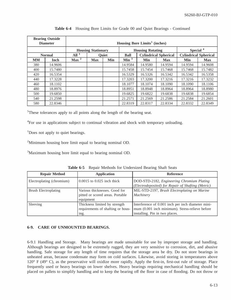
Table 6-4 Housing Bore Limits for Grade 00 and Quiet Bearings - Continued
Bearing OutsideDiameter Housing Bore Limits5 (inches)
Housing Stationary Housing Rotating Special 4
Normal All 1 Quiet Ball Cylindrical Spherical Cylindrical SphericalMM Inch Max 2 Max Min Min 3 Min Max Min Max380 14.9606 14.9584 14.9580 14.9594 14.9594 14.9608400 15.7480 15.7458 15.7454 15.7468 15.7468 15.7482420 16.5354 16.5329 16.5326 16.5342 16.5342 16.5358440 17.3228 17.3203 17.3200 17.3216 17.3216 17.3232460 18.1102 18.1077 18.1074 18.1090 18.1090 18.1106480 18.8976 18.8951 18.8948 18.8964 18.8964 18.8980500 19.6850 19.6825 19.6822 19.6838 19.6838 19.6854540 21.2598 21.2571 21.2569 21.2586 21.2584 21.2601580 22.8346 22.8319 22.8317 22.8334 22.8332 22.8349
5These tolerances apply to all points along the length of the bearing seat.
4For use in applications subject to continual vibration and shock with temporary unloading.
1Does not apply to quiet bearings.
2Minimum housing bore limit equal to bearing nominal OD.
3Maximum housing bore limit equal to bearing nominal OD.
Table 6-5 Repair Methods for Undersized Bearing Shaft Seats
Repair Method Application Reference
Electroplating (chromium) 0.0015 to 0.025 inch thick DOD-STD-2182, Engineering Chromium Plating(Electrodeposited) for Repair of Shafting (Metric)
Brush Electroplating Various thicknesses. Good forpitted or scored areas. Portableequipment
MIL-STD-2197, Brush Electroplating on MarineMachinery
Sleeving Thickness limited by strengthrequirements of shafting or hous-ing.
Interference of 0.001 inch per inch diameter mini-mum (0.001 inch minimum). Stress-relieve beforeinstalling. Pin in two places.
6-9. CARE OF UNMOUNTED BEARINGS.
6-9.1 Handling and Storage. Many bearings are made unsuitable for use by improper storage and handling.Although bearings are designed to be extremely rugged, they are very sensitive to corrosion, dirt, and abusivehandling. Safe storage for any length of time requires that the storage area be dry. Do not store bearings inunheated areas, because condensate may form on cold surfaces. Likewise, avoid storing in temperatures above120° F (49° C), as the preservative will oxidize more rapidly. Apply the first-in, first-out rule of storage. Placefrequently used or heavy bearings on lower shelves. Heavy bearings requiring mechanical handling should beplaced on pallets to simplify handling and to keep the bearing off the floor in case of flooding. Do not throw or
S6260-BJ-GTP-010
6-13

drop bearings. This may scuff or dent the raceways and rolling elements, resulting in noisy operation. Keep bear-ings in their original packing until they are ready for installation. If a new bearing is accidentally exposed to dirt,clean it thoroughly (paragraph 6-9.3.1).
NOTE
NT4 is the latest noise requirement as of this printing.
6-9.2 Inspection. All bearings procured through the military supply system are manufactured by government-qualified firms. Boundary dimensions and tolerance grades standardized by the bearing industry and adopted bythe government and material control information provide the quality control demanded by government resourceinspectors. Because of the critical dimensional and vibration requirements of quiet bearings, a sample from everybearing procurement lot is checked on a continuous basis at the Carderock Division, Naval Surface Warfare Cen-ter (CDNSWC). Bearings marked with the NT symbol followed by the noise requirement number have passedthe requirement for quiet bearings.
6-9.2.1 Before you use a bearing, you must inspect it also. Inspection procedures should consist of the follow-ing:
6-9.2.1.1 Inspect the bearing package date which is recorded on the individual box of every bearing or set ofduplex bearings. If the package date is 10 years or older, file a Quality Deficiency Report and return the bearingsto the issuer. Grease degradation in older bearings can result in reduced bearing life and early equipment failure.This procedure is applicable to both Grade 00 and noise-tested bearings.
6-9.2.1.2 Make sure that you have the correct bearing before removing the packing.
6-9.2.1.3 If the package has been broken but the bearing appears usable, clean the bearing.
6-9.2.1.4 Examine the bearing for corrosion, dirt, and dents. Do not use externally corroded bearings except inemergencies.
NOTE
Bearings packed in grease that have been on the shelf for some time may resisthand rotation at first. This resistance has resulted in the disposal of many goodbearings that were reported to be defective for having dried grease or flat balls.This resistance to rotation is common and will clear up as the grease is worked.Work the bearing by hand for several minutes. Allow it to sit a short time andthen check it again. If it has not cleared up, a problem may indeed exist.
6-9.2.1.5 Rotate the bearing by hand to determine freedom of rotation.
6-9.2.2 If the bearing had been preserved by grease and the application uses oil, remove the grease (paragraph6-9.3.1).
S6260-BJ-GTP-010
6-14

6-9.3 Cleaning. Do not clean bearings as a routine procedure, since foreign matter can easily enter a bearing.Ordinary airborne dust, paint chips, metal filings, brush bristles, cigarette ash, and other foreign objects canseverely damage a bearing. Double-seal and double-shield bearings cannot be cleaned unless manufactured withremovable closures. Normal practice is to inspect these bearings and accept or reject them on the basis of rota-tional smoothness and appearance. Single-seal and single-shield bearings can be cleaned satisfactorily using themethods below if cleaning operations are repeated enough to ensure that all contaminant has been removed.
6-9.3.1 New Bearings. If a new bearing is exposed to any contaminant or grease must be removed, clean thebearing as follows:
a. Secure a clean, dry container and fill it with clean, filtered MIL-L-17331, Lubricating Oil, Steam Turbine andGear, Moderate Service, Military Symbol 2190 TEP.
b. Heat the oil to 140° ± 10° F (60 ° ± 5° C).
c. Immerse the bearing in the oil and rotate and agitate it until all the dirt or grease is washed out. Do not use abrush.
d. Repeat step c., in a second container of clean, filtered oil.
e. When clean, remove the bearing. Cover it and allow the excess oil to drain off. Do not wipe. Do not spin. Donot use compressed air. Handle the bearing with lint-free gloves or cloths.
f. Immediately after, place the bearing in a plastic bag or wrap it in aluminum foil. If the bearing is not to bemounted, rebox, properly identify, and store it.
6-9.3.2 Used Bearings. Thoroughly consider the justification for cleaning and reusing a bearing. Such proce-dures are usually feasible only on larger, more expensive bearings or in emergencies. Before disassembly, deter-mine if replacement bearings are available. When reuse of bearings is considered, dismounting proceduresdemand a high level of care to avoid bearing damage.
6-10. SAFETY PRECAUTIONS.
Observe the following precautions when working with rolling-element bearings:
6-10.1 Unless absolutely necessary, never use a piece of machinery if the bearings are known to be in poor con-dition.
6-10.2 Since good bearing performance depends on proper lubrication, never start a piece of machinery until allbearings are known to be properly supplied with lubricant, both in quality and in quantity.
6-10.3 Determine the normal running temperature of each bearing under all conditions of load and speed, andinvestigate immediately any changes.
6-10.4 The rapid heating of a bearing is a danger sign. A bearing temperature uncomfortably hot to the touch isnot necessarily running overheated. If the bearing has taken an hour or more to reach that temperature, it is prob-ably safe. If that same temperature is reached in a few minutes, expect serious trouble.
6-10.5 Watch the performance of newly installed bearings carefully when first starting a piece of machinery untilit is known that they have reached and are operated at a safe running temperature.
S6260-BJ-GTP-010
6-15
6-10.6 If possible, give newly installed bearings a run-in period applying no load.
6-10.7 Do not use waste cloths to clean bearings or journals. Use only lint-free cloths.
6-10.8 When renewing rolling-element bearings be sure to use the type and grade designed on the machinerydrawings and as specified by allowance parts list and the technical manual.
6-10.9 Never try to repair damaged rolling-element bearings by replacing balls or rollers.
6-10.10 Do not remove a rolling-element bearing from its original container and wrapping until every prepara-tion has been made to install it.
6-10.11 When installing rolling-element bearings, be sure that the inner race is seated tightly against the shaftshoulder.
6-10.12 Avoid excessive lubricant in rolling-element bearings. Very little lubricant is required. Excessive lubri-cant fills the spaces between elements. This impedes free movement and causes early failure.
6-10.13 Be particularly careful to seal housings of rolling contact bearings against the entry of foreign matter.
6-11. CARE OF MOUNTED BEARINGS.
6-12. HANDLING, MAINTENANCE AND LUBRICATION OF MOUNTED BEARINGS
The greatest threats to mounted bearings are brinelling of the races caused by poor handling, false brinellingof the races caused by wearing away of material due to vibratory motion during storage or transport, and corro-sion due to a lack of preservative compound on bearing surfaces. All these conditions can be avoided with cor-rect care.
6-12.1 Handling and Storage. Abusive handling and improper storage of assembled machinery can negate allpervious precautions taken to prevent premature bearing failure.
6-12.1.1 If partial assemblies with mounted bearings (such as rotors) are stored, coat the bearings with a preser-vative and securely wrap with plastic or foil. Do not use cloth wrapping.
6-12.1.2 When handling heavy assembled machinery, always use mechanical lifting equipment. Fasten suspen-sion lines only to the lifting lugs provided. Any other attached point may distort the housing or bend the shaft,resulting in bearing misalignment. Never attach a suspension line to the shaft extension.
NOTE
Perform shipboard maintenance in accordance with the Maintenance Require-ment Cards (MRC) where installed.
S6260-BJ-GTP-010
6-16

6-12.2 Maintenance. Bearings are an integral part of the assembly, making it impossible to observe their opera-tion. Do not routinely disassemble machinery just to inspect the bearings or lubricant. The following methodshave been established to help assess mounted bearing condition.
6-12.2.1 Preoperational Inspection. A considerable amount of time can be saved by performing the followingpreoperational checks:
a. Review the unit’s history. For grease-lubricated relubricable bearings: if the unit has been shut down or instorage for over 1 year, remove the end caps to check the grease. If the end caps cannot be removed withoutmajor disassembly and, if available records indicate that the bearings have not been lubricated in the past year,lubricate the unit (paragraph 6-12.3.4). In units with shafts installed or stowed vertically and using other thansealed bearings, the grease may move to a point below the bearing and will not provide lubrication on startup.
b. Rotate the shaft by hand. The shaft shall turn freely without binding. Locate and eliminate the cause of anyabnormal resistance to rotation.
c. On units with shaft extensions, use a dial indicator (paragraph 2-53) to check the shaft total indicated runout(FIR) at the extreme end.
d. Check the overall appearance of the unit for indications of bumping or dropping. Severe bearing misalignmentcan result from abusive handling.
e. Ensure that all hardware is tight.
f. When possible, dynamically balance rotating parts in accordance with the applicable specification or techni-cal manual. An inplace balance of the assembled unit may be required.
6-12.2.2 In-Service Inspection. The length of the run-in period of new bearings may vary considerably, but 24hours is usually long enough. Major difficulties will almost always appear during this period. Monitor the bear-ing temperature, noise, and vibration. When the load can be varied, run the unit under minimum load for severalhours and then gradually increase to full load at hourly increments. Rolling-element bearings will normally havean extremely long service life if properly designed for the application, correctly installed, and maintained asrequired. Because of this, the actual date of bearing installation is not usually known unless accurate records aremaintained. Periodic casual inspection of bearing performance is, therefore, desirable. A daily casual inspectionfor noise, vibration, and temperature will tend to reduce unexpected failures.
6-12.2.3 Temperature. All bearings generate heat during operation. Bearing temperature is a function of load,speed, lubricant, motor losses, and ambient temperature. Military specifications for motors limit bearing operat-ing temperature by limiting the temperature of the outer bearing ring to either 194° F (90° C) or 230° F (110°C), depending upon which specification revision was in effect when the motor was procured. Bearing operatingtemperature at rated load is measured with a temperature sensor on the outer ring of the bearing by the motormanufacturer during qualification resting. These test results are shown on the motor master drawing, in the HeatRun section. The motor master drawing is normally located in the technical manual for the driven auxiliary ormotor. Properly designed bearing systems operate at steady temperature levels. Small temperature changes withinthe safe operating range are normal as the grease alternately lumps into the races and channels again, or as theload changes. On the other hand, sharp unexpected temperature increases usually indicate trouble, possiblyimpending failure. Bearing temperature can be routinely checked by placing a hand on the housing. If the sur-face feels too hot to touch, examination is necessary. Do not, however, insert a liquid-in-glass thermometer intothe bearing housing, either against the bearing or in the grease or oil reservoir. Take measurements on the hous-ing close to the bearing. Self-indicating bimetallic and gas thermometers common to shipboard use require a sig-nificant immersion length and will not accurately record surface temperature. Instruments for measuring surface
S6260-BJ-GTP-010
6-17
temperature are commercially available and are usually supplied with tip-sensitive pencil probes. These are idealfor accurately measuring remote bearing temperature. A thermometer with the bulb embedded in a mound of clayor putty and securely fastened on the external housing surface close to the bearing will usually provide satisfac-tory temperature measurement. Commercially available temperature-sensitive crayons (such as Tempilstiks orThermomelt) or tape (such as Temp-Plate) can satisfactorily indicate temperature. If the normal operating tem-peratures on the exterior of the motor housing in the vicinity of the bearings are known from experience, exces-sive bearing temperature can be identified by measuring these surface temperatures on the motor housing. If thenormal operating temperatures are not known, an uncertainty results when determining bearing overtemperaturethis way since the outer ring is from 41° F to 59° F (5° C to 15° C) hotter than the exterior housing. The tem-perature measurement made on the housing must be compared to that in the motor master drawing. Be sure toadjust the housing measurements for differences in ambient temperature associated with the drawing measure-ment. The value on the drawing is also measured at rated load. The load on the ship is often less than the ratedload. Therefore, the value measured on the housing will be less than that on the drawing due to the loading dif-ference and due to the 41°F to 59°F (5°C to 15°C) differential mentioned above. If the bearing temperature isunexpectedly high in relation to past experience or if the temperature exceeds the maximum design limit, furtherexamination is necessary. Bearing overheating may result from many sources. The most common ones are as fol-lows:
6-12.2.3.1 If the temperature rises immediately after startup in a grease-bearing application, it is probablybecause the grease has slumped into the races. Stopping the unit and allowing the grease to cool in the channeledstate will usually cure this condition.
6-12.2.3.2 If the temperature rises immediately after startup in an oil lubrication application, stop the unit andimmediately check that the oil level is in accordance with the instruction. If the level is satisfactory, the circu-lating system may be clogged or inoperative.
6-12.2.3.3 If the temperature rise occurs immediately after the bearing has been lubricated with grease, the causemay be too much grease or the wrong type of grease. To avoid this condition, follow the correct lubrication pro-cedure for both quantity and type. If the bearing is overgreased, remove the drain plug and allow the excess todrain. If the grease is the wrong type, disassemble and clean the bearing.
6-12.2.3.4 Excessive loading of the bearing. This can be caused by excessive bearing preload, excessive shaftor housing interference, or external bearing overload. These are usually caused by mounting or assembly errors.
6-12.2.3.5 Error in alignment during mounting.
6-12.2.3.6 Tight-fitting seals.
6-12.2.4 Noise and Vibration. In shipboard applications, noise is structureborne, airborne, and fluidboure. Noiseis caused by vibration. All rolling-element bearings generate vibration. In rotating machinery, the amplitude ofbearing vibration is a function of bearing quality, seat geometry, and fitup. Electronic equipment can measure thestructure-borne noise of rotating equipment in noise critical applications. Quiet bearings are usually used innoise-critical applications because they generate low levels of vibration. Instruction manuals on the use of thistype of electronic equipment and the analysis of results have been issued to participating ships and should beconsulted. In non-noise-critical applications, a rough vibration check can be made by placing a hand on themachine frame. If a mechanic’s stethoscope is not available, use a metal tool to listen for unusual noises. Holdthe ear to one end of the tool, rod, or pipe and hold the other end to the machine frame as close to the bearing
S6260-BJ-GTP-010
6-18

as possible. Only a soft purring sound should be heard. Learn to recognize this sound by practicing on bearingsknown to be in good condition. Some typical sounds and their causes listed below:
NOTE
The listening method of detecting trouble is comparative. It should not be thebasis for tearing down a piece of equipment unless the operator has considerableexperience.
6-12.2.4.1 Squeaking noise. Inadequate lubrication or insufficient load (preload).
6-12.2.4.2 Metallic Tone. Insufficient internal bearing clearance caused by excessive shaft or housing interfer-ences, or axial preloading caused by improper adjustment or inadequate lubrication.
6-12.2.4.3 Smooth, Clear Tone. Marks in the stationary raceway caused by brinelling. When the sound inten-sity varies regularly with each revolution, the rotating ring has been brinelled.
6-12.2.4.4 Intermittent Noise. Usually unique to ball bearings and indicates a damaged ball.
6-12.2.4.5 Crunching Noise. Presence of dirt. Clean the bearing immediately.
6-12.3 Lubrication. The bearing lubricant is chosen during equipment design, and an equivalent type must beused during maintenance. As a rule, all rolling-element bearings may be lubricated with oil. They are grease-lubricated in most electric motor applications. The use of grease, though, is limited by operating speeds, loads,and temperature.
6-12.3.1 Rolling-element bearing lubrication serves the following primary functions:
6-12.3.1.1 Prevents metal-to-metal contact between the races and rolling elements that is not true rolling.
6-12.3.1.2 Lubricates the sliding contact that exists between the cage and other bearing parts.
6-12.3.1.3 Lubricates the sliding contact between the rollers and guiding elements in roller bearings.
6-12.3.1.4 Protects the highly finished surfaces of rolling elements and races from corrosion.
6-12.3.1.5 In grease applications, helps seal against the entry of foreign matter.
6-12.3.1.6 In oil applications, provides cooling by dissipating heat.
6-12.3.2 Characteristics of Grease. Grease is a mixture of a lubricating oil, a metallic-base soap, and a thick-ener. The soap and thickener hold the oil. Oil separates from the soap under pressure or agitation. The grease actssomewhat like an oil sponge.
S6260-BJ-GTP-010
6-19

6-12.3.2.1 A ball bearing will sling nearly all the grease away from the ball train during normal operation. Onlya small amount of oil is retained on the balls and raceways. Excess oil is pressured out as grease slumps downinto the ball train. The oil is then reabsorbed into the grease. This permits a small amount of oil to provideadequate lubrication for long periods.
6-12.3.2.2 As grease repeatedly slumps into a bearing which is operated for a long time, some of the grease isthrown clear and may become mixed with air. It will have a milky appearance, but it will not become less effec-tive as a lubricant. Some of the soap may have part of its oil drawn out during long periods of operation. Thiswill leave hard lumps of pure soap, which serve no lubrication purpose. They will not reduce the reliability ofthe bearings, though, as long as there is an adequate supply of oil-rich grease to work its way into the bearings.
6-12.3.3 Grease Lubrication. For applications involving moderate speeds and temperatures, the simplicity andreliability of grease lubrication is desirable. Open, single-shield, and single-seal bearings as mounted usuallyrequire the periodic addition of grease and are termed relubricable bearings. Double-shield and double-seal bear-ings are permanently lubricated at the factory and require no further grease. Such bearings are prelubricatedbearings. The service life of prelubricated bearings is limited to the effective life of the original grease charge.Prelubricated bearings are usually restricted to applications with favorable grease life characteristics. Electricmotors with prelubricated bearings can be recognized by the absence of grease fittings or provision for attachinggrease fittings and by attached warning plates stating DO NOT LUBRICATE. Relubricable bearings in newmachines are packed with grease when they leave the factory. The frequency with which grease must be addeddepends on the service of the machine and the tightness of the housing seals. Avoid using too much greasebecause it results in an excessive and rapid temperature increase. Add grease only when required.
6-12.3.4 Grease Addition. A bearing is lubricated only by the grease that is immediately next to and in contactwith it. The grease in this location may gradually stop lubricating because the oil is depleted, leaving just thethickener. The grease farther away from the bearing may still be in good condition. Therefore, it is a good ideato add a small amount of grease close to the bearing at specified intervals. The preferred method of adding greaseis to open the housing so that the bearing and old grease can be examined and new grease can be placed directlyin and next to the bearing. For Navy equipment where extensive disassembly would be required to repack thebearing with grease, the bearings are designed so that fresh grease can be added to the bearing housing by agrease cup, without the need for disassembly. Housing designs vary considerably, making relubrication with agrease cup something of an art. Be careful not to overgrease the bearings. The following procedure is recom-mended:
NOTE
Never lubricate electrical machinery with a grease gun. If grease gun fittings arefound on electrical machinery, remove them and install a suitable grease cup fit-ting and pipe plug.
a. Select the proper grease cup and clean it thoroughly. Select the correct grease and, using a clean spatula, fillthe cup. Screw the cup together, and squeeze out a ribbon of grease until clean grease emerges.
b. Secure the machine. Tag it OUT OF SERVICE . Disassemble it as required. Wipe all dirt from the outsideof the grease fill-and-vent plugs.
c. Remove the vent plug and make sure that the passage is open by probing it with a clean screwdriver, stiff wire,or similar item. Old grease may be forced out the vent. Note the condition of the displaced grease. Dark greaseindicates either the onset of oxidation or the presence of dirt. Grease containing metallic particles and dirt
S6260-BJ-GTP-010
6-20
indicates trouble. Rub a little grease between the fingers. If water is present, it will form droplets. Particleswill be felt easily. When contaminants are present, corrective action is necessary.
d. Remove the pipe plug from the grease supply passage. Observe the condition of the grease in the pipe. Ifacceptable, proceed. If unacceptable, remove the grease pipe, if so designed, clean it, pack it full of the cor-rect grease, and reinstall it. If the pipe is empty, remove it, clean it, fill it with the correct grease, and rein-stall it. If the grease in the supply passage is unacceptable and the pipe is not removable, remove the bearingend cap or end bell and hand-pack the bearing.
e. Mount the grease cup on the equipment. Fill the grease cup.
f. Screw down on the grease cup as far as it will go. If grease is drawn into the cup as the cap is unscrewed,the preferred action is as follows:
(1) Screw the cap back into the cup as far as it will go to force the grease back into the lubrication supplypassage.
(2) Remove the cup from the equipment.
(3) If relubrication is complete, install the supply passage pipe plug and operate the equipment as recom-mended.
(4) If relubrication is not complete, remove the cap from the cup and reinstall the cup on the equipment.
(5) Load the cup with grease and screw down on the cap as far as it will go, as previously recommended.
(6) Repeat these steps as required until relubrication is complete.
g. Remove the grease cup and install the supply passage pipe plug. Start the machine and allow it to run for 30minutes. Replace the vent pipe plug.
An alternate procedure to the above is to drill a small hole in the cap after the cup is removed fromthe equipment. The hole diameter should not be larger than 1/16th inch. The cap must be removed fromthe cup prior to drilling. The cap must be thoroughly cleaned after drilling to remove all metal chips. Anyburrs around the drilled hole must be removed prior to cleaning. The operator must hold a finger over thehole to prevent grease from escaping while screwing the cap.
6-12.3.5 Grease Replacement. Replace all old grease in the bearing housings when the machinery is disas-sembled for any reason. Remove the bearing caps or covers that permit observation of bearing and lubricant.Depending on the conditions found, one of the following actions may be necessary.
6-12.3.5.1 If the grease in the bearing is still good, replace only the grease in the housing where possible.
a. Wrap the bearing in clean, lint-free material.
b. Scrape the old grease from all accessible portions of the housing. Be careful not to introduce dirt into thehousing or the bearing. Do not wipe.
NOTE
Do not flush the bearing cap with oil if the oil could leak into the windings ofelectrical machinery. It may be impractical to flush out the complete housingwithout removing the bearing.
c. Flush out the bearing cap or cover it with clean, warm 2190 TEP oil. Apply a light coat of grease to theunpainted bearing housing surfaces.
d. Drain well.
S6260-BJ-GTP-010
6-21

e. In horizontal applications with an open bearing, pack the housing on both sides of the bearing half full ofgrease.
f. In horizontal applications with a single-seal or single-shield bearing, pack the housing opposite the seal orshield half full.
g. In vertical applications with an open bearing, or a single-seal or single-shield on top, pack the housing belowthe bearing three-quarters full.
h. In vertical applications with a single-seal or single-shield on the bottom of the bearing, the amount of greaseabove the bearing is critical. Limit the housing pack above the bearing to an amount that will lie on the sta-tionary bearing ring (one-third to one-half full). Do not overpack or allow grease to slump into bearing. Thegrease will bleed into the bearing during normal operation.
i. In all cases lightly coat the bearing with grease.
j. Pack the entire length of the grease inlet passage and inlet pipe with clean grease.
k. Reassemble the bearing housing.
6-12.3.5.2 If the grease in the bearing is sticky or rancid, contains dirt or foreign matter, or is generally deterio-rated, wash out the bearing (paragraph 6-9.3.1). If the bearing shows excessive wear or if any parts are damaged,replace the bearing. Otherwise, pack the bearing with clean grease (paragraph 6-12.3.5). Prepare the bearinghousing and pack the grease in the housing (paragraph 6-12.3.5.1). Observe proper replacement procedures.
6-12.3.6 Preferred Navy bearing greases for shipboard auxiliary machinery are as follows:
NOTE
Other sizes of containers may be available under other NSNs. If a specifiedgrease is obsolete, consult NAVSEA S9086-H7-STM-010/CH 262, ″LubricatingOils, Greases, Hydraulic Fluids, and Lubricating Systems,″ for an approved sub-stitute.
6-12.3.6.1 Bearings operating below 230° F (100° C) in non-noise-critical applications use DOD-G-24508,Grease, High Performance, Multipurpose , available in 1-pound cans, NSN 9150-00-149-1593.
6-12.3.6.2 Bearings operating above 230° F (100° C) in non-noise-critical applications, except electric motorbearings, use MIL-L-15719, Lubricating Grease (High-Temperature, Electric Motor, Ball and Roller Bearings) ,available in 8-ounce tubes, NSN 9150-00-256-5358.
6-12.3.6.3 Quiet bearings for noise-critical applications use DOD-G-24508, grease available in 1-pound cans,NSN 9150-00-149-1593.
6-12.3.6.4 Where specifically approved for the application, use MIL-G-81322, Grease, Aircraft, General Pur-pose, Wide Temperature Range, or DOD-G-24508 available in the following:
6-12.3.6.4.1 MIL-G-81322, 8-ounce tube, NSN 9150-00-181-7724.
6-12.3.6.4.2 DOD-G-24508, 8-ounce tube, NSN-9150-00-149-1592.
S6260-BJ-GTP-010
6-22
6-12.3.6.5 Roller bearings in surface ship control surface systems use MIL-G-24139, Grease, Multipurpose,Water Resistant , available in 5-pound cans, NSN 9150-00-180-6382.
6-12.3.7 Oil Lubrication. For oil-lubricated bearings, refer to NAVSEA S9086-HN-STM-010/CH 244.
6-13. NOISE-TESTED BEARINGS.
The present noise-tested (NT-3 and NT-4) bearings are manufactured to very precise specifications fordimensions, geometrics, and quality of finish. For example, a size 313 bearing, with a 65mm (2.5591 inches) boreand eight balls of 15/16 inch diameter, has 0.0002 inch maximum tolerances on the inner and outer diameters.It can be expected to have taper and circularity of the rings held to within 0.00005 inch. The raceways are ground,lapped, and honed to curvature and waviness tolerances within 0.00001 inch. The maximum ball-to-ball variationin size will be about 0.000005 inch. The circularity of each ball will vary less than 0.000001 inch.
6-13.1 Raw Steel Stock. This degree of quality control extends to the raw steel stock. The processes of pour-ing, cooling, and forging of the steel are designed to provide optimum durability of the finished bearing. Cutting,machining, and various heat treatments are also designed to provide maximum durability.
6-14. MECHANICAL DAMAGE.
Mechanical damage to bearings may occur during installation or during operation of the motor. Mechanicaldamage is usually shown by damaged shields, damaged retainers, or chipped and scratched raceways.
6-15. CORROSION.
Corrosion appears in many forms. Although corrosion is undesirable, it does not always reduce the reliabil-ity of a bearing. It does not necessarily require a bearing change.
6-15.1 Rust. Rust on a new bearing or on a bearing already in a motor may be caused by moisture or corro-sive gases in the air. If rust appears on the outside, there is probably rust on the raceways and balls. The bear-ing must be suspected to be unfit unless there is assurance that there is no internal rust.
6-15.2 Reactions. Reactions within a lubricant may frequently cause staining of the bearing rings or retainer.Dark blue, green, or brown stains which are not due to excessive heat are usually harmless. They do not requirereplacement of a bearing. Metal shields or retainers occasionally have tinned surfaces. They become dark blue orblack under the action of some lubricants. This is also harmless.
6-15.3 Fretting. Fretting corrosion results from a combination of chemical and mechanical attack. It occursbetween steel surfaces subjected to repeated mechanical loading. Fretting corrosion consists of the pitting of thesteel surfaces and the formation of a brown corrosion product which is often found on the inner ring or on theouter diameter of a bearing. It is harmful only if it appreciably damages surfaces, or if pitting threatens to destroyproper bearing fitup. Fretting corrosion in a bearing bore warns that the shaft may be slightly undersized. Theshaft may then have to be built up and reground to proper size. The same is true in the case of the outer ring andits housing.
6-16. ELECTRIC ARCING.
Electric arcing rarely causes bearing damage, but it occasionally occurs in motor-generator sets. It firstappears as a light ″frosting″ or roughening of the ball or raceway surfaces. It causes the grease to turn black.
S6260-BJ-GTP-010
6-23

Electric arcing will occur in the zone of thinnest oil films; therefore, it will usually be concentrated in the loadedportions of the ball tracks on each ring. It is possible for all arcing to occur at only one part of the motor rota-tion. This will cause all of the marking to appear over a short arc on the inner raceway and in the leaded zoneof the outer raceway. Under a microscope, electrical damage looks different than dirt damage. The arcing pro-duces pitting with a more irregular outline. Heavy arcing appears as a blasted area. There is evidence of the melt-ing of the steel in the bottom of the pits.
6-17. BEARING REPLACEMENT.
6-17.1 Preliminary Inspection. When equipment using rolling-element bearings requires repair, conduct anin-place inspection. The nature of the casualty can frequently be determined, and this may eliminate unnecessarydisassembly. Check for the following:
6-17.1.1 Freedom of rotation. If binding occurs, check close running clearances for noncontact. In coupledunits remove the coupling and rotate each unit independently.
6-17.1.2 Excessive heating of the bearings. Eliminate other heat sources.
6-17.1.3 Excessive bearing noise. Eliminate other noise sources.
6-17.1.4 Lose or broken bolts or parts. Check the foundation.
6-17.1.5 Distorted bearing supports, cracked or bent bearing caps, and loose balance rings.
6-17.1.6 Loose or inaccurate coupling alignment, if used.
6-17.1.7 Coastdown time. Compare with previous experience. Short times indicate high torque. Listen to theunit during coastdown. It may pass through resonances that may pinpoint a faulty component.
6-18. WORK AREA AND TOOLS.
The average shop fails to realize the necessity for the highest degree of cleanliness to prevent bearing con-tamination. An indication of the conditions required of the bearing manufacturer to ensure the cleanliness ofpackaged bearings is as follows:
6-18.1 The air entering the processing space shall be filtered and air conditioned.
6-18.2 The floor, walls, and ceiling shall be dust-free.
6-18.3 Entry to the are shall be restricted by double doors.
6-18.4 The air in the room shall contain no more than 100 particles, 5 microns (0.0002 inch) or larger, per cubicfoot of air.
6-18.5 All personnel shall wear lint-free coats, head and shoe covers, and lint-free gloves.
S6260-BJ-GTP-010
6-24

6-18.6 Nothing extraneous to the operation (food, drink, cigarettes) shall be brought into the area.
6-19. CLEANLINESS.
Positive cleanliness control shall be exercised. Although establishing surgically clean white room facilitiesmay be unfeasible, the following conditions should be adhered to:
6-19.1 In any work area make cleanliness the rule, orderliness a habit.
6-19.2 Handle rolling-element bearings in a clean, dry location.
6-19.3 Avoid areas in which turning, grinding, sandblasting, or blowing is carried on.
6-19.4 The work area shall be away from any machines that create dust-laden air or disturbing vibrations.
6-19.5 A clean workbench with a smooth metal top should be available - dirt and small metal chips cling easilyto wooden bench tops.
6-19.6 When it is impossible to move the assembled equipment to a shop, remove the partial assembly thatrequires bearing work to a suitable location.
6-19.7 If even this is impossible, sweep out and vacuum the assembly area in the machinery space before begin-ning reassembly.
6-19.8 Ready all components and tools so that assembly can proceed without delay.
6-19.9 Redirect the airflow from the ventilation ducts and shut down unneeded equipment that will circulate dirtand dust.
6-20. TOOLS.
The tools that will be needed are largely determined by the size of the job and should be assembled beforebeginning work. Measuring instruments shall be stabilized at the same temperature as the parts requiring mea-surement. The following basic tools and equipment are recommended for bearing replacement work:
6-20.1 Arbor Press. This should large enough to accommodate the assemblies with which you are working. Itshould be kept clean and in good repair. The face of the ram shall be smooth and perfectly square with its axis.The press should operate smoothly and with accurate control.
6-20.2 Hand Tools. Hammers and drifts should not be of soft, flaky material such as brass, bronze, or alumi-num. A weighted-head hammer with composition or leather ends and a soft, cold-rolled steel drift are preferred.Bearing locknut spanner wrenches are standard for smaller sizes. An efficient locknut spanner (figure 6-3) can bemanufactured in any shop.
6-20.3 Bearing Pullers. Pullers should conform to GGG-P-781, Puller, Mechanical Puller Attachment,Mechanical, and Puller Set, Mechanical. Every ship has such pullers.
S6260-BJ-GTP-010
6-25

6-20.4 Torque Wrenches. Use torque wrenches corresponding to GGG-W-686, Wrench, Torque , to properlytorque bolts on end bells, end caps, and bearing locknuts.
6-20.5 Convection Oven. Bearings still in their original intimate wrap are placed on a shelf in an oven thermo-statically controlled to a nominal 203° F ± 10° F (95° C ± 5° C). Depending on bearing size, a soak period of1/2 to 1 hour is usually enough. When several bearings are heated simultaneously, they should not be stacked,but placed side by side. Many shops have manufactured ovens using light bulbs mounted in a box lined with foil.In such apparatus, temperature should be controlled by a thermostat rather than by the less reliable method ofcontrolling lamp size and the size of the enclosure. Do not use a convection oven when both inner and outer ringsare to be fitted at the size time, since reducing interference on one ring will only increase it on the other.
6-20.6 Bore Heater. A light bulb or electric heating element is inserted in the bearing bore. An advantage ofthis method is that the inner ring is heated while the outer ring remains relatively cool. This permits easy han-dling during mounting. In this method heating is controlled by ensuring that the heating element is centered inthe bearing bore. Ring temperature should not exceed 203° F (95° C). Cover the bearing to avoid contamination.
6-20.7 Induction Heater. The induction heater is basically a transformer in which the bearing ring acts as ashort-circuited second winding. A high current is induced in the bearing ring, resulting in an extremely rapidheating rate. This heater is not approved for ring expansion of quiet bearings. When using for other bearings, usea contact pyrometer or other reliable method to limit ring temperature to 203° F (95° C). The bearing shall neverbe left unattended in this heater. Disconnect the heater power cord when installing or removing the bearing. Coverthe bearing to avoid contamination and demagnetize it before mounting.
6-20.8 Oil Bath. The hot oil bath method consists of heating bearings in oil at a temperature below 203° F (95°C): Do not use this with quiet bearings.
S6260-BJ-GTP-010
6-26

6-20.9 Wiping and Handling Materials. Lint-free, clean cloths for covering partial assemblies and for wipinggrease and dirt from shafts, housings, and hands should be on hand in ample quantities. Do not use waste, bur-lap, or cheesecloth. Use clean, insulated gloves when handling bearings. Wear clean clothes when mountingbearings.
Figure 6-3 Typical Locknut Wrench and Table of Dimensions
S6260-BJ-GTP-010
6-27
6-20.10 Grease. Keep limited stocks of grease at hand. Small containers are preferred as a measure to avoidcontamination. Apply grease with a clean metallic or plastic spatula.
6-20.11 Measuring Instruments. For installing quiet bearings, dial-indicating comparative bore and snap gagereadings in units of 1/1,000 (0.0001) inch are preferred. Such gages measure the difference between the measuredobject and a standard of known dimensions. Standards are provided for each shaft and housing size correspond-ing to a particular bearing size. (Repair ships and yards should have these instruments. They are desirable but notalways practical for shipboard.). All ships should have carefully calibrated inside and outside micrometers read-ing to 0.0001 inch, a dial indicator reading to 0.0001 inch, and master precision gage blocks for checking.
6-21. DISASSEMBLY AND BEARING REMOVAL.
6-22. GENERAL INFORMATION.
Care in removing a bearing is as important as the care in installing a new bearing. Do not destroy any evi-dence of why a bearing failed, as this information may lead to the solution of the trouble. In an emergency, andif a replacement is unavailable, it may be necessary to reinstall the bearing (paragraph 6-9.3.1). If the machineis dismantled for reasons other than bearing replacement, bearings should not usually be removed. In suchinstances, the bearing shall be tightly wrapped in a lint-free covering while other work is performed.
6-22.1 Consider the complexity of the job and the experience of the personnel with the fundamentals of bearinghandling. Obtain drawings and study the bearing scheme carefully. Read all available repair instructions thor-oughly and completely before taking any action. Discuss the entire repair procedure so that each person knowswhat to do.
6-22.2 Use proper tools, and use them for their intended purpose. Chiseling, prying, and needless hammering aredefinitely discouraged. Before disassembly, matchmark all adjacent parts including end bells, stator feet, cartridgecovers, end caps, coupling halves, and so forth so that they are remounted in their exact original position. Whenremoving parts over the shaft, be careful not to damage the shaft surface or threading. As small parts are removed,place them in a tote pan. Tag large parts for identification.
6-23. BEARING REMOVAL.
Dismount bearings by one of the methods below. Pressure for removal (and installation) of a bearing shall beapplied directly to the interference-fitted ring (figure 6-4). In most applications, the inner ring is tight on the shaft.In a few cases the outer ring is tight in the housing. In a very limited number of applications both rings will betight. The technical manual or applicable ship or equipment drawing should provide the fitup limits. If it isimpossible to apply the force directly to the interference-fitted ring, the bearing will undoubtedly be unfit for fur-ther service.
CAUTION
Never use a naked flame to heat a shaft, bearing, or housing. This can sig-nificantly distort the components.
6-23.1 Arbor Press Method. If possible, place the bearings to be removed and the shaft or housing on whichthey are mounted into an arbor press. This is one of the best methods of removing bearings; use it whenever pos-sible. When working with a shaft assembly, place the bearing inner rings against a pair of flat blocks of the same
S6260-BJ-GTP-010
6-28

thickness. Take care to keep the shaft straight to prevent damage from cocking. Use a firm, steady pressure andforce the shaft out (figure 6-5.a). When working with housing, support the housing against a pair of flat blocksof equal thickness. Using a sleeve, push against the outer ring, or both rings, and force the bearing out (figure6-5b).
6-23.2 Puller Method. If an arbor press is unavailable, use pullers that conform to GGG-P-781. The pullerattachment (type XII in the specification), which can be inserted behind the bearing inner ring, should be usedin conjunction with puller types I or VII. Puller jaws (type I) should be set so that they will pull straight and notslip. An uneven pressure in pulling may cock the bearing, so exert an even pressure with a straight pull (figure6-6). Always use shaft center protectors of type XIII, class 3 or class 4, conforming to (GGG-P-781. Whenenough space is unavailable for installing the type XII attachment behind the bearing, it may be possible toremove the bearing by pulling on the inner cap or cartridge. This should be done by manufacturing a split spacerthat, when filled between the bearing inner ring and the housing cap or cartridge, will prevent loading of thebearing outer ring (figure 6-7).
6-23.3 Seized Bearing. Remove a seized bearing as follows:
CAUTION
Never use a torch to loosen a bearing. A torch may cause shaft distortion.
S6260-BJ-GTP-010
6-29
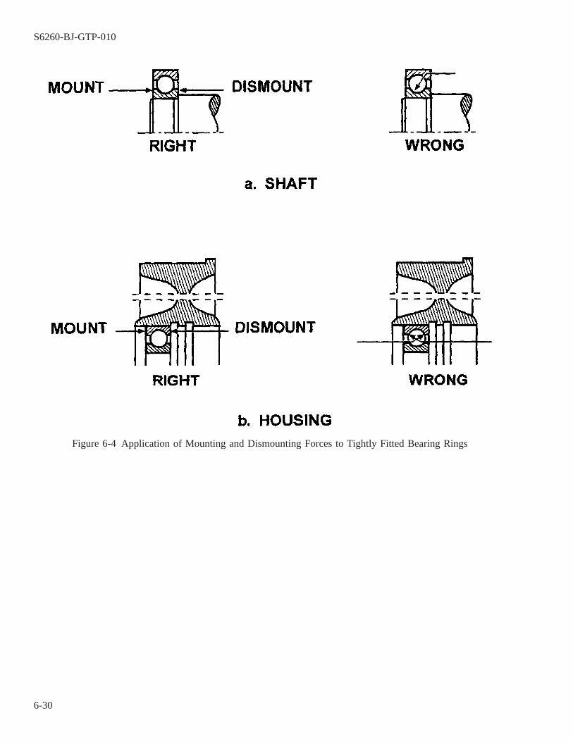
Figure 6-4 Application of Mounting and Dismounting Forces to Tightly Fitted Bearing Rings
S6260-BJ-GTP-010
6-30
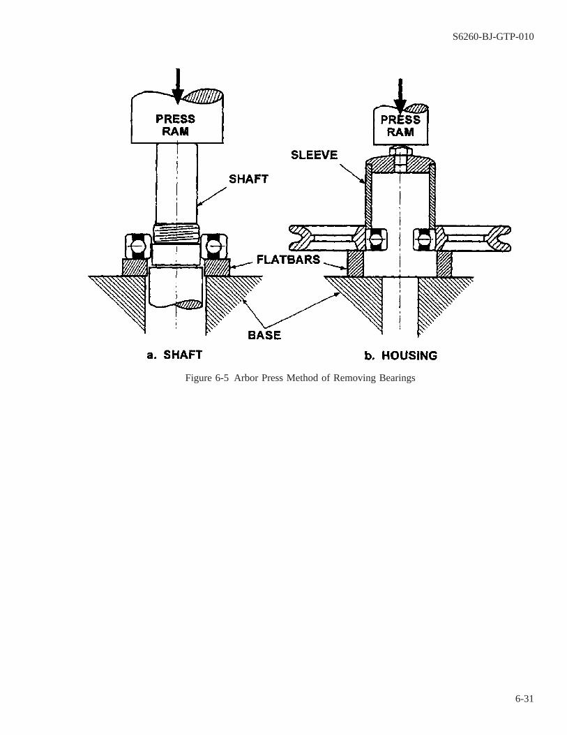
Figure 6-5 Arbor Press Method of Removing Bearings
S6260-BJ-GTP-010
6-31

CAUTION
Never use a torch to loosen a bearing. A torch may cause shaft distortion.
a. If the bearing does not move after using a bearing puller set with moderate pressure, the bearing is seized onthe shaft. Use a high-speed grinder to remove the bearing.
WARNING
Wear safety eyeglasses or goggles when grinding.
NOTE
While using the high-speed grinder, use rags to protect the rest of the motor frommetal particles.
Figure 6-6 Bearing Puller Removal Using Split Puller Attachment and Shaft Protector
S6260-BJ-GTP-010
6-32
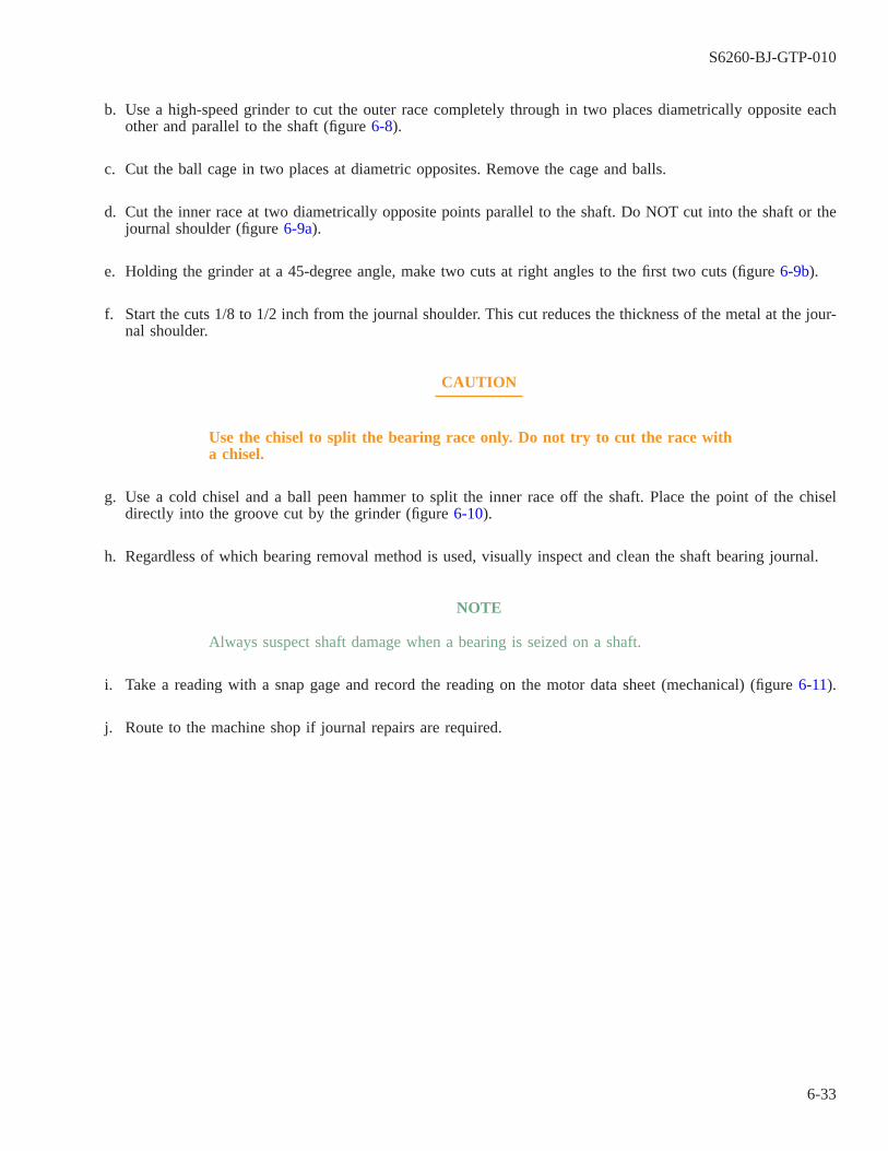
b. Use a high-speed grinder to cut the outer race completely through in two places diametrically opposite eachother and parallel to the shaft (figure 6-8).
c. Cut the ball cage in two places at diametric opposites. Remove the cage and balls.
d. Cut the inner race at two diametrically opposite points parallel to the shaft. Do NOT cut into the shaft or thejournal shoulder (figure 6-9a).
e. Holding the grinder at a 45-degree angle, make two cuts at right angles to the first two cuts (figure 6-9b).
f. Start the cuts 1/8 to 1/2 inch from the journal shoulder. This cut reduces the thickness of the metal at the jour-nal shoulder.
CAUTION
Use the chisel to split the bearing race only. Do not try to cut the race witha chisel.
g. Use a cold chisel and a ball peen hammer to split the inner race off the shaft. Place the point of the chiseldirectly into the groove cut by the grinder (figure 6-10).
h. Regardless of which bearing removal method is used, visually inspect and clean the shaft bearing journal.
NOTE
Always suspect shaft damage when a bearing is seized on a shaft.
i. Take a reading with a snap gage and record the reading on the motor data sheet (mechanical) (figure 6-11).
j. Route to the machine shop if journal repairs are required.
S6260-BJ-GTP-010
6-33

6-24. COMPONENT INSPECTION AND REPAIR.
If the shaft was damaged during bearing removal, restore it before measuring or reworking the surfaces.Inspect and repair the components as follows:
a. Inspect the end bells, cartridges, or other bearing-carrying parts for splits and cracks. If any are found, repairor replace the piece.
b. Examine the shaft and housing seats for damage, wear, or other deterioration. If there is no evidence of suchdeterioration or wear and if the seats are not suspect, the bearing seats need not be measured or reworkedbefore installing new bearings during shipboard bearing replacements. Bearing seats shall be inspected duringall other bearing replacements, even if there is no evidence of wear or deterioration. The original dimensionsare usually adequate and should nor be changed merely to conform to some other limits.
c. If there is evidence of seat damage, or wear, inspect the bearing seats for conformance to the dimensions andtolerance limits in NAVSEA S9086-HN-STM-010/CH 244. Because bearing tolerances require measuringaccuracies of 0.0001 inch, using a dial-indicating, comparative snap gage (paragraph 2-62) for measuring shaft
Figure 6-7 Split Spacer Allows Use of Cover to Remove Inner Ring
S6260-BJ-GTP-010
6-34

diameters and a dial-indicating bore gage for measuring housing diameters and a dial-indicating bore gage(paragraph 2-58) for measuring housing diameters. Standard hand-held micrometers are inadequate forinspecting bearings. If the seat roundness one-half diameter tolerance limit is greater than 0.0004 inch, a dialindicator (paragraph 2-53) with 0.0001 graduations may be used to inspect seat roundness. As measurementsare being made, frequently check the gage back to the gage block, and correct any variations.
S6260-BJ-GTP-010
6-35
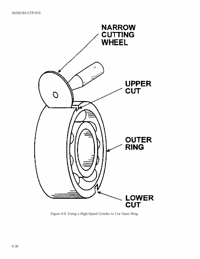
Figure 6-8 Using a High-Speed Grinder to Cut Outer Ring
S6260-BJ-GTP-010
6-36
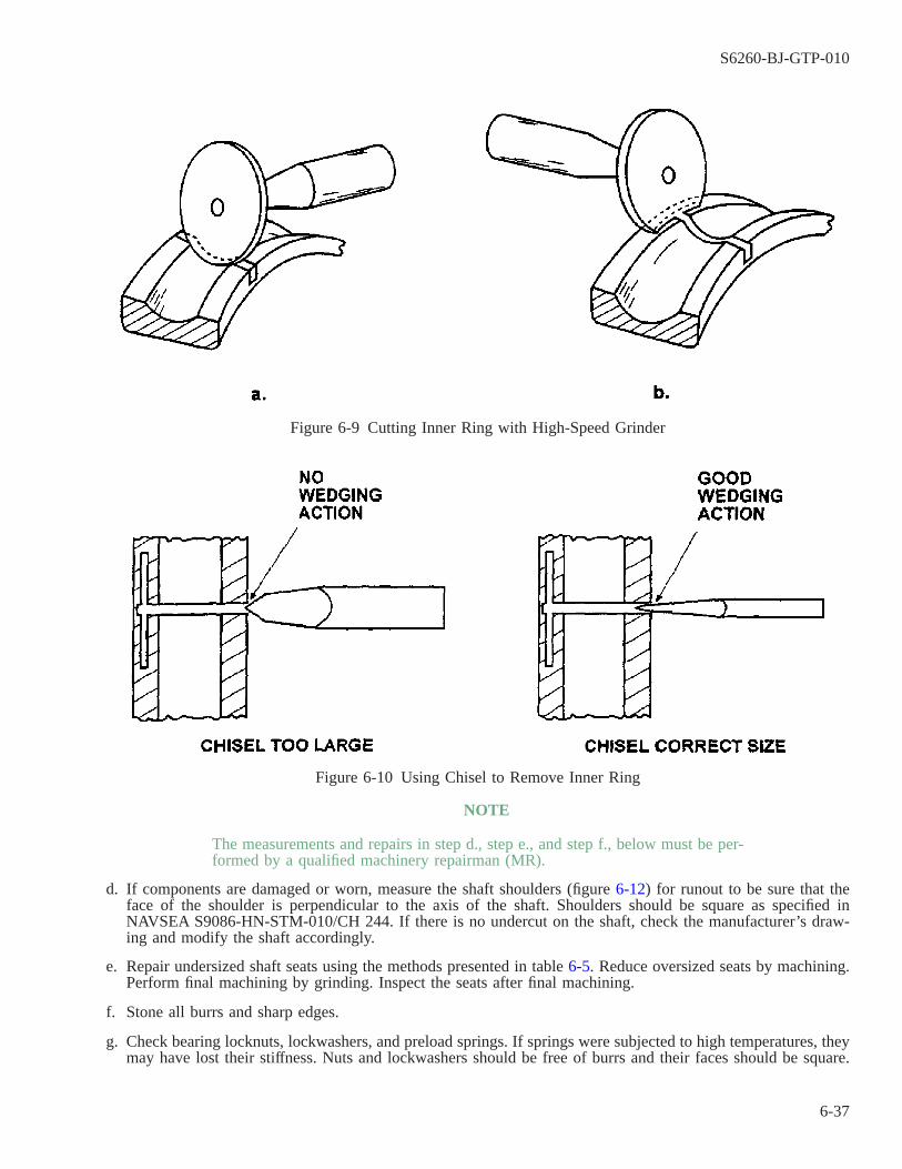
NOTE
The measurements and repairs in step d., step e., and step f., below must be per-formed by a qualified machinery repairman (MR).
d. If components are damaged or worn, measure the shaft shoulders (figure 6-12) for runout to be sure that theface of the shoulder is perpendicular to the axis of the shaft. Shoulders should be square as specified inNAVSEA S9086-HN-STM-010/CH 244. If there is no undercut on the shaft, check the manufacturer’s draw-ing and modify the shaft accordingly.
e. Repair undersized shaft seats using the methods presented in table 6-5. Reduce oversized seats by machining.Perform final machining by grinding. Inspect the seats after final machining.
f. Stone all burrs and sharp edges.
g. Check bearing locknuts, lockwashers, and preload springs. If springs were subjected to high temperatures, theymay have lost their stiffness. Nuts and lockwashers should be free of burrs and their faces should be square.
Figure 6-9 Cutting Inner Ring with High-Speed Grinder
Figure 6-10 Using Chisel to Remove Inner Ring
S6260-BJ-GTP-010
6-37
Self-locking nuts that still function may be reused. Abutting faces of spacers, slingers, and sleeves shall besquare and parallel and shall retain a good finish in accordance with NAVSEA S9086-HN-STM-010/CH 244.
h. Clean all components thoroughly, using approved methods and solvents or detergents as dictated by safetyregulations. Once cleaned, store parts in a clean, dust-free area until needed for assembly.
6-25. BEARING INSTALLATION AND ASSEMBLY.
6-25.1 Nearly all rolling-element bearing applications require an interference fit on at least one of the bearingrings. Therefore, all mounting methods are based on obtaining the necessary interference without undue effortand with no risk of damage to the bearing. The most important rule when mounting and dismounting bearings isthat the mounting pressure shall never be applied in such a way that it is transmitted through the rolling elements.Apply the mounting force directly against the interference-fitted ring (figure 6-13). Bearings shall remain pack-aged until they are required for installation and shall not be cleaned routinely. All unnecessary handling of bear-ings is definitely discouraged. Observe the conditions described in paragraph 6-9.1 to ensure cleanliness and toavoid bearing contamination. The same personnel who disassembled the machinery should also assemble it.
6-25.2 Ring expansion will simplify the mounting of interference-fitted bearing rings. Expand the rings by oneof the methods described in paragraphs 6-20.5 through 6-20.8. Each method requires care, because bearing dam-age invisible to the eye can result. The convection oven method is preferred in most cases and should always beused for installing quiet bearings. The other methods listed are less desirable and should be used only by a skilledmechanic who has the expertise to avoid bearing damage. All methods except the convection oven requireremoval of the bearing intimate wrap. With the wrap removed, take care during ring expansion to avoid contami-nation. When the bearing outer ring is mounted with an interference fit in the housing, the housing, dependingon size, can also be expanded by these methods. Do not freeze the bearing or shaft because corrosion may resultfrom condensation.
CAUTION
Never use a naked flame to heat a shaft, bearing, or housing. This can sig-nificantly distort the components.
S6260-BJ-GTP-010
6-38

Figure 6-11 Motor Data Sheet (Mechanical)
S6260-BJ-GTP-010
6-39

6-25.3 Obtain drawings and study the bearing scheme carefully. Read all available repair instructions thoroughlyand completely before taking any action. Discuss the entire assembly procedure so that each person knows whatto do. Use extreme care in assembling all parts. Be careful not to damage mating surfaces or shaft threading.Avoid undue force.
6-25.4 Mount bearings by one of the methods below. The entire shaft or housing including keyways, threads,splines, grooves, and so on, shall be thoroughly clean, since foreign matter or dirt between the inner ring and
Figure 6-12 Measuring Shaft Shoulder Runout
Figure 6-13 Pressing Bearings on Shaft with an Arbor Press
S6260-BJ-GTP-010
6-40

shoulder can cause misalignment (figure 6-14). Bearings will not seat firmly against the shaft shoulder unless theshoulder is clean. Apply a thin coat of clean oil to the bearing seats before assembly. Before mounting bearingson the shaft or in the housing, ensure the correct bearing orientation to avoid unnecessary disassembly. Draw aline through the bearing and compare sides. If the bearing is exactly the same on both sides, either side can bemounted first. When the sides are different, the bearing must be mounted only one way. If you mount a bearingbackwards, you will find out later because the machine cannot be assembled or because it fails rapidly. A seal orshield that is on the wrong side may interfere with bearing lubrication or may permit contaminants to enter thebearing. Special instructions for mounting duplex bearings are in paragraph 6-30.
6-25.5 Bearing Locknuts. Bearing locknuts ensure that the bearing mounts hold the bearings correctly.
6-25.5.1 A conventional locknut and lockwasher are shown in figure 6-15.
6-25.5.2 Self-locking locknuts (figure 6-16), sometimes referred to as prevailing torque retaining nuts , areessentially the same size and material as the conventional locknuts. They are equipped with a nylon compressioncollar, however, that has a temperature limit of 300° F (149° C). The collar eliminates the need for a lockwasher.Self-locking locknuts permit convenient assembly and disassembly. The resilient collar follows the metal threadsin engagement during assembly. This develops compression of the collar, with the metal threads of the shafteliminating the space between the shaft threads and the collar. This compression develops tension between themating parts, providing better locking and more protection against loosening, especially from vibration. Locknutsmust be installed using a bearing locknut spanner wrench (figure 6-3) and torque wrench. For conventional lock-nuts with lockwashers (figure 6-15), use torque values in table 6-6. For self-locking locknuts (figure 6-16), usetorque values in table 6-7.
Figure 6-14 Effect of Dirt in Mounting Bearings
S6260-BJ-GTP-010
6-41
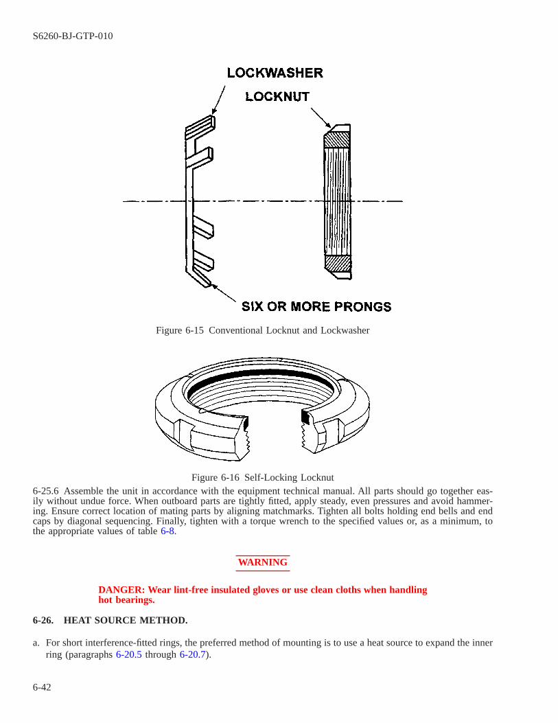
6-25.6 Assemble the unit in accordance with the equipment technical manual. All parts should go together eas-ily without undue force. When outboard parts are tightly fitted, apply steady, even pressures and avoid hammer-ing. Ensure correct location of mating parts by aligning matchmarks. Tighten all bolts holding end bells and endcaps by diagonal sequencing. Finally, tighten with a torque wrench to the specified values or, as a minimum, tothe appropriate values of table 6-8.
WARNING
DANGER: Wear lint-free insulated gloves or use clean cloths when handlinghot bearings.
6-26. HEAT SOURCE METHOD.
a. For short interference-fitted rings, the preferred method of mounting is to use a heat source to expand the innerring (paragraphs 6-20.5 through 6-20.7).
Figure 6-15 Conventional Locknut and Lockwasher
Figure 6-16 Self-Locking Locknut
S6260-BJ-GTP-010
6-42

b. A 100° F (38° C) difference between the parts to be fitted should be enough for the bearing to slide all theway to the shoulder. Any difficulty may indicate the shaft is oversized.
c. Install the locknut while the bearing is hot, and torque to the value specified in table 6-8.
d. Cover the assembly while left to cool to protect it from atmospheric dirt. Loosen the locknut and retorque afterthe assembly cools.
6-27. ARBOR PRESS METHOD.
If a heat source is unavailable, the next best method is to use an arbor press and a piece of tubing.
a. Remove any burrs, sharp corners, and so on from the shaft or housing, and carefully center the bearing at thebeginning of the seat-the seat corner radius of the bearing will help.
b. Place the tube on the appropriate ring face, and apply pressure with the arbor press ram (figure 6-13a and6-13c). With uniform pressure, the bearing should go on smoothly all the way. If it sticks or requires extraforce at any point, stop the pressure. Look for cocking burrs on the seat or a tapered seat.
6-28. PARALLEL BLOCK METHOD.
For shaft interference-fitted rings, another way of using the arbor press is to use parallel blocks under thebearing inner ring and press the shaft into the bearing (figure 6-13b).
Table 6-6 Torque Values for Bearing Locknuts (Dry Threads)
Bearing Bore Code Torque Value (ft-lb)
00 10-2001 10-2002 10-2003 10-2004 12-3505 23-5006 32-6007 39-7008 50-8009 64-9010 67-10011 82-12512 99-15013 131-17514 152-20015 173-25016 197-27517 222-32518 248-37519 277-42520 345-47521 380-55022 380-55024 380-55026 380-550
S6260-BJ-GTP-010
6-43
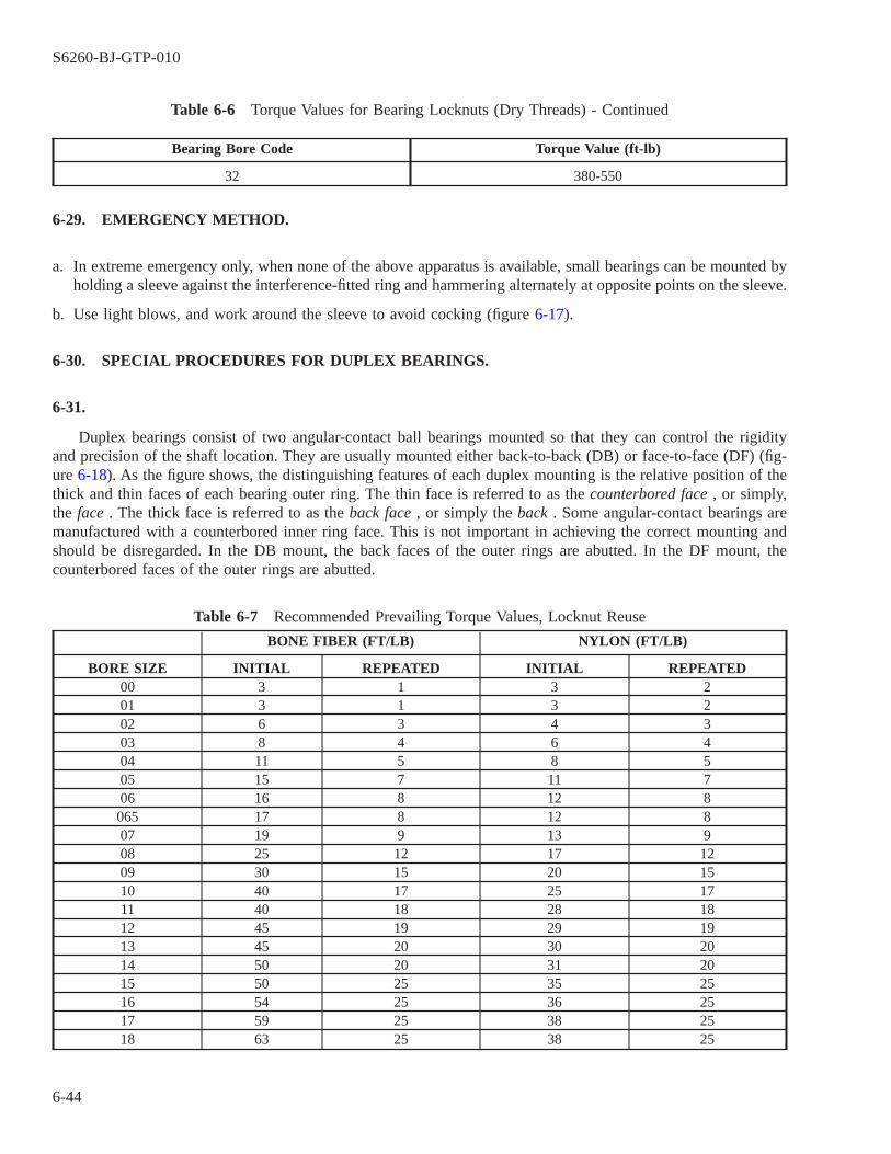
Table 6-6 Torque Values for Bearing Locknuts (Dry Threads) - Continued
Bearing Bore Code Torque Value (ft-lb)
32 380-550
6-29. EMERGENCY METHOD.
a. In extreme emergency only, when none of the above apparatus is available, small bearings can be mounted byholding a sleeve against the interference-fitted ring and hammering alternately at opposite points on the sleeve.
b. Use light blows, and work around the sleeve to avoid cocking (figure 6-17).
6-30. SPECIAL PROCEDURES FOR DUPLEX BEARINGS.
6-31.
Duplex bearings consist of two angular-contact ball bearings mounted so that they can control the rigidityand precision of the shaft location. They are usually mounted either back-to-back (DB) or face-to-face (DF) (fig-ure 6-18). As the figure shows, the distinguishing features of each duplex mounting is the relative position of thethick and thin faces of each bearing outer ring. The thin face is referred to as the counterbored face , or simply,the face . The thick face is referred to as the back face , or simply the back . Some angular-contact bearings aremanufactured with a counterbored inner ring face. This is not important in achieving the correct mounting andshould be disregarded. In the DB mount, the back faces of the outer rings are abutted. In the DF mount, thecounterbored faces of the outer rings are abutted.
Table 6-7 Recommended Prevailing Torque Values, Locknut Reuse
BONE FIBER (FT/LB) NYLON (FT/LB)
BORE SIZE INITIAL REPEATED INITIAL REPEATED00 3 1 3 201 3 1 3 202 6 3 4 303 8 4 6 404 11 5 8 505 15 7 11 706 16 8 12 8065 17 8 12 807 19 9 13 908 25 12 17 1209 30 15 20 1510 40 17 25 1711 40 18 28 1812 45 19 29 1913 45 20 30 2014 50 20 31 2015 50 25 35 2516 54 25 36 2517 59 25 38 2518 63 25 38 25
S6260-BJ-GTP-010
6-44

Table 6-7 Recommended Prevailing Torque Values, Locknut Reuse -
Continued
BONE FIBER (FT/LB) NYLON (FT/LB)
BORE SIZE INITIAL REPEATED INITIAL REPEATED19 65 30 40 3020 68 30 40 3021 71 30 41 3022 74 30 42 3024 79 30 44 3026 81 30 45 3028 83 35 46 3530 86 35 48 3532 88 35 50 3534 91 35 53 3536 95 40 56 4038 98 40 60 4040 102 40 63 40
6-31.1 Duplex pairs are either flush ground or modified for preload or end play. All single angular-contact bear-ings that are flush ground can be duplexed. Where preload or end play is specified, however, only single bear-ings from a single manufacturer, with the same contact angle and with faces ground for the same modified con-dition, should be duplexed. To avoid complications in selecting single bearings for duplexing, use only bearingsfurnished as duplex pairs. For precision pairs such as quiet bearings, both bores and outside diameters are selectedto match closely on tolerance. Also, the high point of radial runout of each ring is marked on one face of boththe inner and the outer rings of each bearing. Depending on the manufacturer, the radial runout mark could be aburnished spot, a circle, or an arrow. During installation these marks must be lined up at the same angular posi-tion so that the high points of runout of both bearings coincide (figure 6-19). These bearings must be procuredunder the proper stock number for the specified application because a preloaded bearing will not operate satis-factorily in an application where a bearing with a loose internal setup is required, and vice versa. An early fail-ure would result in either case.
Table 6-8 Recommended Torque (in Foot-Pounds) for Bolts, Nuts, and Studson End Caps and End Bells
Hexagon Head Bolt Grades 1and 2
Hexagon Head Bolt Grade 5 Hexagon Head Bolt Grade 8
Bolt, Nut, StudSize (Inch)
No Marking Carbon SteelCorrosion-Resistant Steel
Marking Carbon Steel AlloySteel
Marking Carbon Alloy Steel
1/4 2-4 6-8 9-125/16 4-8 13-17 18-253/8 6-12 23-30 35-457/16 10-20 35-50 55-701/2 15-30 55-75 80-1109/16 23-45 80-110 110-150
S6260-BJ-GTP-010
6-45
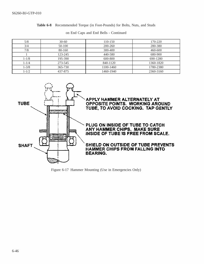
Table 6-8 Recommended Torque (in Foot-Pounds) for Bolts, Nuts, and Studs
on End Caps and End Bells - Continued
5/8 30-60 110-150 170-2203/4 50-100 200-260 280-3807/8 80-160 300-400 460-6001 123-245 440-580 680-900
1-1/8 195-390 600-800 690-12801-1/4 273-545 840-1120 1360-18201-3/8 365-730 1100-1460 1780-23801-1/2 437-875 1460-1940 2360-3160
Figure 6-17 Hammer Mounting (Use in Emergencies Only)
S6260-BJ-GTP-010
6-46

Figure 6-18 Duplex Bearing Arrangements Showing Relation of the Outer Ring Faces
Figure 6-19 Bearing Ring Radial Runout Alignment of Precision Bearing Pairs
S6260-BJ-GTP-010
6-47

6-31.2 Assuming that the bearings are heated as indicated in paragraphs 6-20.5 through 6-20.7, duplex bearingsshall be installed one at a time.
a. After orienting the inner beating to achieve the correct duplex mount, press it firmly into contact with the shaftshoulder, or in a few cases, a backing sleeve or oil impeller.
b. The bearing should be held against the shaft shoulder by the locknut and a sleeve. The sleeve should haveparallel faces and be at least as wide as the outer bearing (figure 6-20). (Disassemble the old bearing, increasethe bore diameter, and use as the spacer.)
c. Do not remove the holding device until the entire assembly is at room temperature. Cover the bearing whileit cools.
6-31.3 Install the outer bearing in a similar manner.
a. Before installing the outer bearing, orient it to achieve the correct duplex mounting. If so marked, align thepoints of maximum radial runout so that these marks are aligned in the same angular position as those on theinner bearing.
b. Bearing rigidity with the DB mount is achieved by the clamping action of the beating locknut through theinner rings. It is therefore desirable to rotate the bearing outer rings by hand while tightening the locknut. Thisallows the rolling elements to seat and avoid brinelling the races.
c. Do not loosen the locknut once it is installed. Install any sleeve or hub of an adjacent part that is clampedbetween or in conjunction with the bearings before tightening the locknut. With the DF mount, the bearingsrigidity is achieved by clamping action of the cap and housing shoulders through the bearing outer rings.
d. Rotate the shaft by hand during final assembly while tightening the housing end cap bolts in a diagonalsequence to allow the rolling elements to seat and to avoid brinelling the races.
e. After final tightening of the bolts with a torque wrench, enough clearance must exist between the end cap andthe housing to ensure actual clamping of the rings (figure 6-18b).
6-31.4 If heat is not used for installing duplex bearings, use an arbor press. Be certain the bearings seat firmlyagainst the shaft shoulder and each other. With the DB mount, press the second bearing on far enough so that thelocknut threads can be fully engaged and then use the locknut to force the bearings together and fully clamp them.
Figure 6-20 Mounting of Duplex Bearing (DB Mount Shown)
S6260-BJ-GTP-010
6-48

6-32. BEARING LOCKNUT TORQUES.
Unless otherwise specified, torque all bearing locknuts to the appropriate value specified in table 6-6.
6-33. GREASE PACK.
6-33.1 At installation, pack the bearing with grease. Quiet bearings are supplied with the correct amount and typeof operational lubricant. With all other grades of bearings, double-shield, double-seal, and single-seal bearingsare shipped with the correct amount and type of operational lubricant. Single-shield and open bearings, however,are shipped with a preservation slush. Only open and single-shield bearings, therefore, excluding quiet bearingsof these types, will require grease to be placed into the bearing at installation. Pack grease in a bearing from oneside until the grease just begins to come past the balls on the opposite side. Distribute this grease uniformlywithin the bearing air space. Apply a light coat of grease to any remaining ungreased surfaces of the bearing.
6-33.2 With all relubricable bearings, fill the bearing housing cavity 20 to 50 percent full. The lower limit appliesto vertical applications, the higher limit to horizontal applications (paragraph 6-12.3.4). Bearing operationalgreases for shipboard machinery should conform to those indicated (paragraphs 6-12.3.6.1 through 6-12.3.6.5),depending on service application. The grease should be applied with a clean metallic or plastic spatula. Apply alight coat of grease to all unpainted bearing housing surfaces. With prelubricated bearings (double-sealed ordouble-shielded), do not add grease to the bearing housing cavity.
6-33.3 For motors with relubricable bearings, if the grease inlet passage and inlet pipe have not had old greasecleaned out, clean it out. Then pack the entire length of the passage and pipe with new grease to prevent corro-sion.
6-34. PRELOAD SPRINGS.
Preload springs are used to reduce ball skidding, thereby reducing noise and increasing bearing life. It isimportant that such springs be installed correctly during assembly. Various types of springs are used for this pur-pose. In most applications one spring or a series of springs is clamped between the bearing outer race and theinner or outer bearing cover. Check the drawing to determine the correct orientation.
6-35. AXIAL RUNOUT.
Where quiet bearings are used, the maximum axial runout should not exceed the values listed in table 6-9.Bearing axial runout is the sum of the runout of the bearing outer ring face with reference to the shaft and theinner ring face with reference to the housing. This measurement is made during the final stages of assembly onunits where the design allows making the measurements (figure 6-21: add measurements B and C). Valuesobtained for measurement A on figure 6-21 indicate shaft radial runout. Large values of radial runout indicatebent shafting that may cause excessive radial vibration and should be minimized.
6-35.1 Alignment. When assembling two or more machinery components such as pumps, compressors, blow-ers, or motors, it is essential that some degree of alignment be maintained between respective shafting. The mostcommon method of specifying alignment of close-coupled and rigid-couplet units is to list face and rim runoutrequirements. The face reading indicates angular misalignment between two flanges. The rim reading measuresaxial misalignment between the shafts (figure 6-22). Acceptable limits should be as specified on the drawing orin the technical manual. If face runouts are unlisted, use the appropriate value from table 6-9 applicable to hous-ings. Rim runouts should not exceed 0.0005 inch and are normally less, as specified.
S6260-BJ-GTP-010
6-49

6-36. OIL LUBRICATION.
In oil-lubricated bearing applications, be sure to add the lubricant to the correct level before operating themachinery.
Table 6-9 Recommended Maximum Axial Runout for Bearing, Shaft, andHousing Assemblies Using Quiet Bearings
Bearing Bore Code 200 and 300Series Bearing Bore
Maximum Recommended Axial Runout ofAssembly (inch)
(Inch) (MM)00 to 03 0.3937 10 0.0004
to to0.6693 17
04 to 10 0.7874 20 0.0005to to
1.9685 5011 to 17 2.1654 55 0.0010
to to3.3465 85
18 to 26 3.5433 90 0.0015to to
5.1181 130
6-37. POSTREPAIR INSPECTION.
6-38.
To ensure correct operation after bearings have been installed, check rotating machinery for torque, noise,and temperature when possible while it is still in the shop.
6-38.1 Torque. Any indication of high torque, binding, or drag means trouble. The completely assembledmachine should turn freely without binding. High torque can be caused by excessive axial preload, pressure froman improperly located cover plate, or misalignment of the shaft housing.
6-38.2 Noise. Bearings should operate at low noise levels. Any unusual operating nose after installation shallbe carefully analyzed before the bearings are considered to be the cause.
6-38.3 Temperature. Noise and excessive torque will usually be accomplished by a rise in temperature. Anoticeable rise also may be caused by excess grease.
6-38.4 Recordkeeping. Maintain documentation on as-released measurements and shop test performance untilthe component performs satisfactorily aboard ship. Such a record can be of great value if the application exhib-its operating trouble after installation.
6-38.5 Reinstallation Tests. Follow the inspection procedures described in Chapter 12.
S6260-BJ-GTP-010
6-50
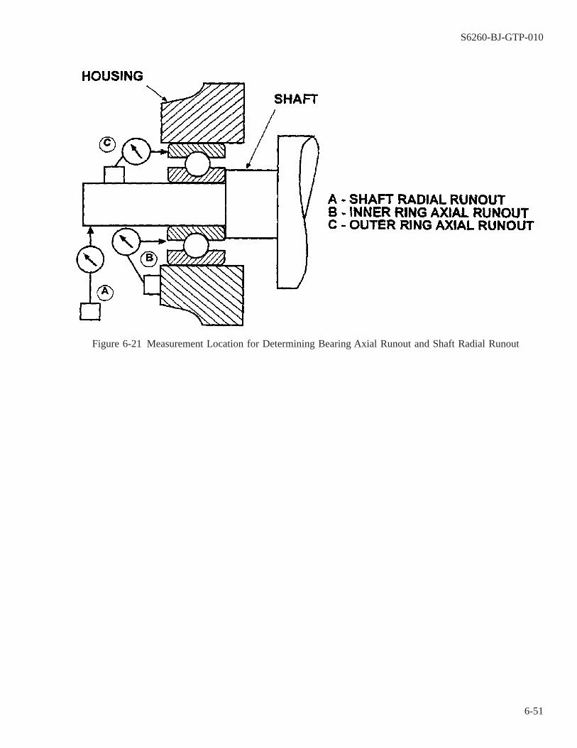
Figure 6-21 Measurement Location for Determining Bearing Axial Runout and Shaft Radial Runout
S6260-BJ-GTP-010
6-51

6-39. MOTOR BEARING CONVERSION: EXTENDED-LIFE DOUBLE SEAL BALL BEARINGS
6-39.1 To reduce motor maintenance and repair costs, the following actions have been taken to implement theproper use of EXTENDED-LIFE double seal (ELDS) bearings.
1. Limits of applicability for ELDS bearings have been developed that will ensure acceptable bearing life inNavy motors, see paragraph 6-39.2.
2. APLs for motors meeting the applicability requirements have been modified to identify ELDS bearings. IfELDS bearings are not indicated in an APL, applicability may be reviewed using paragraph 6-39.2.
3. NSNs for the ELDS bearings have been developed and are indicated in table 6-10.
Figure 6-22 Measurement Location for Determining Face and Rim Runouts
S6260-BJ-GTP-010
6-52

6-39.2 Applicability. Motors NOT under the cognizance of NAVSEA 08, that meet all of the motor criteria ofparagraph 6-39.3, should be repaired using ELDS bearings.
6-39.3 Motor Criteria.
1. Motor must be installed on a surface ship.
2. Motor must NOT be under the cognizance of NAVSEA 08.
3. Commercial motors are not eligible. Motors must have been furnished to the Navy in accordance with MIL-M-17060, MIL-M-17413 or MIL-M-17059.
4. Motors using one or more noise-quiet bearings per MIL-B-17931 are not eligible.
5. Bearings originally furnished with the motor must both be type 111 bearings per FF-B-171.
6. The use of ELDS bearings is limited to motors where the full load speed and the size of both bearings are asfollows:
a. Maximum bearing size 306 or 206 and full load rpm between 1,801 and 3,600 rpm.
b. Maximum bearing size 313 or 213 and full load rpm between 1,201 and 1,800 rpm.
c. Maximum bearing size 318 or 218 and full load rpm less than 1,200 rpm.
6-39.4 In addition to the requirements of this technical manual for bearing care, installation and removal, therepair process using ELDS bearings includes the following requirements:
1. Only ELDS bearings can be used. Other double seal bearings will not provide an acceptable bearing life.
2. Both bearings of each converted motor must be ELDS bearings.
3. A label plate must be permanently attached to the motor indicating, ″Do Not Lubricate″.
4. Grease fills and drains, if present, must be fitted with a pipe plug, securely fastened. Fittings to accommodategrease guns must be replaced with pipe plugs.
5. After repair, the shipboard databases affecting maintenance requirements such as the Equipment Guidance List(EGL) must be updated to reflect the change in maintenance requirements for the converted motor. Theinstalling activity must advise the scheduling activity to submit a change to the EGL and other databases asappropriate.
6. Where APL changes are initiated to convert to ELDS bearings, a COSAL feedback report should be submit-ted, providing the NSN and part number for the ELDS bearing. Only the ELDS bearing should be indicatedon the APL.
Table 6-10 ELDS Bearings NSNs and Part Numbers
SIZE P/N NSN
201 6201-2RS1C3/GHY 3110-01-492-0221202 6202-2RS1C3/GHY 3110-01-491-0233203 6203-2RS1C3/GHY 3110-01-491-0234204 6204-2RS1C3/GHY 3110-01-491-6636205 6205-2RS1C3/GHY 3110-01-451-9166
S6260-BJ-GTP-010
6-53

Table 6-10 ELDS Bearings NSNs and Part Numbers - Continued
SIZE P/N NSN
206 6206-2RS1C3/GHY 3110-01-451-9165207 6207-2RS1C3/GHY 3110-01-451-9164208 6208-2RS1C3/GHY 3110-01-451-9170209 6209-2RS1C3/GHY 3110-01-451-9252210 6210-2RS1C3/GHY 3110-01-492-1831211 6211-2RS1C3/GHY 3110-01-518-0937303 6303-2RS1C3/GHY 3110-01-493-3750304 6304-2RS1C3/GHY 3110-01-451-9153305 6305-2RS1C3/GHY 3110-01-451-9158306 6306-2RS1C3/GHY 3110-01-451-9159607 6307-2RS1C3/GHY 3110-01-451-9161308 6308-2RS1C3/GHY 3110-01-451-9167309 6309-2RS1C3/GHY 3110-01-451-9168310 6310-2RS1C3/GHY 3110-01-490-6683311 6311-2RS1C3/GHY 3110-01-492-0223312 6312-2RS1C3/GHY 3110-01-490-6848313 6313-2RS1C3/GHY 3110-01-492-0191314 6314-2RS1C3GHY 3110-01-492-0226315 6315-2RS1C3/GHY 3110-01-494-0993316 6316-2RS1C3/GHY 3110-01-492-0188317 6317-2RS1C3/GHY 3110-01-492-0219318 6318-2RS1C3/GHY 3110-01-493-3749
S6260-BJ-GTP-010
6-54
CHAPTER 7
PREPARATION FOR MOTOR RECONDITIONING
7-1. SCOPE.
This chapter contains information on the six preliminary procedures to be followed when a motor arrives atthe electric motor repair shop for reconditioning and repair. A reconditioned motor is one that has been disas-sembled for cleaning or other repairs but is not to be rewound. Topics include:
7-1.1 Cleaning the motor (paragraph 7-2).
7-1.2 Drying the motor (paragraph 7-10).
7-1.3 Testing (paragraph 7-16).
7-1.4 Cleaning electrical equipment after seawater damage (paragraph 7-18).
7-2. CLEANING THE MOTOR.
7-3. METHODS OF CLEANING.
It is sometimes possible to recondition an electric motor without rewinding. Initial electrical tests (see Chap-ter 5) may indicate that rewinding is unnecessary. However, there may be contaminants such as dirt, oil, grease,or other foreign material in the motor. In such cases, the motor must be cleaned. Only approved methods shouldbe used to do this. Approved methods are:
7-3.1 Suction,
7-3.2 Wiping,
7-3.3 Air pressure,
7-3.4 Water washing with compounds, and
7-3.5 Steam spraying with compounds (Steam jenny).
CAUTION
Be certain that the tube or nozzle, if used, has no sharp edges which mightscrape insulation.
7-4. SUCTION.
Vacuum suction is the preferred method of removing dry materials like dust, chips, and dirt. A small noncon-ductive nozzle or tube may have to be connected to the vacuum cleaner to allow better access to the surface and
S6260-BJ-GTP-010
7-1

narrow openings. Use a soft brush to remove any foreign matter sticking to the winding. Hold the vacuum nozzleclose while brushing lightly with the soft brush. The vacuum will pick up material loosened by the brush.
CAUTION
Take care when removing the material. Chips or other rough matter adher-ing to the cloth may scratch or remove insulation.
Foreign matter may be pushed or pressed into an inaccessible opening if thematerial to be removed is close to such an opening. This will create moreserious problems.
7-5. WIPING.
Use a dry lint-free cloth to wipe over the exposed surfaces to remove loose foreign material. Use a clean clothto avoid carrying dirt or grit from one part of a surface to another. This method will remove loose dirt.
WARNING
Improper or playful use of the high-pressure hose may cause severe injuryto internal organs and eardrums. Never allow compressed air to contact orenter any persons body. Always use proper safety equipment such as facemasks and goggles.
CAUTION
Ensure that any accumulation of moisture in the air lines has been removed.Remove any moisture by operating the air away from the stator to becleaned long enough to blow moisture out of the line.
Ensure that foreign material is actually being removed by blowing it fromthe stator. Ensure that material is not deposited deeper into inaccessiblecrevices.
Air pressure must not exceed 30 pounds per square inch.
Ensure the removal of dirt-laden air whenever compressed air is used toremove foreign material. Ensure that there is suction on the opening at theend opposite the air jet.
Use compressed air with caution. Abrasive particles may puncture insulationand be forced under insulating tape.
S6260-BJ-GTP-010
7-2
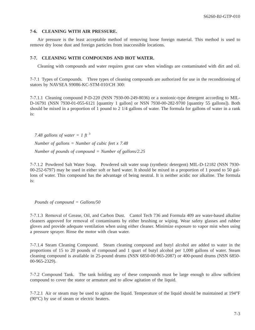
7-6. CLEANING WITH AIR PRESSURE.
Air pressure is the least acceptable method of removing loose foreign material. This method is used toremove dry loose dust and foreign particles from inaccessible locations.
7-7. CLEANING WITH COMPOUNDS AND HOT WATER.
Cleaning with compounds and water requires great care when windings are contaminated with dirt and oil.
7-7.1 Types of Compounds. Three types of cleaning compounds are authorized for use in the reconditioning ofstators by NAVSEA S9086-KC-STM-010/CH 300:
7-7.1.1 Cleaning compound P-D-220 (NSN 7930-00-249-8036) or a nonionic-type detergent according to MIL-D-16791 (NSN 7930-01-055-6121 [quantity 1 gallon] or NSN 7930-00-282-9700 [quantity 55 gallons]). Bothshould be mixed in a proportion of 1 pound to 2 1/4 gallons of water. The formula for gallons of water in a rankis:
7.48 gallons of water = 1 ft 3
Number of gallons = Number of cubic feet x 7.48
Number of pounds of compound = Number of gallons/2.25
7-7.1.2 Powdered Salt Water Soap. Powdered salt water soap (synthetic detergent) MIL-D-12182 (NSN 7930-00-252-6797) may be used in either soft or hard water. It should be mixed in a proportion of 1 pound to 50 gal-lons of water. This compound has the advantage of being neutral. It is neither acidic nor alkaline. The formulais:
Pounds of compound = Gallons/50
7-7.1.3 Removal of Grease, Oil, and Carbon Dust. Cantol Tech 736 and Formula 409 are water-based alkalinecleaners approved for removal of contaminants by either brushing or wiping. Wear safety glasses and rubbergloves and provide adequate ventilation when using either cleaner. Minimize exposure to vapor mist when usinga pressure sprayer. Rinse the motor with clean water.
7-7.1.4 Steam Cleaning Compound. Steam cleaning compound and butyl alcohol are added to water in theproportions of 15 to 20 pounds of compound and 1 quart of butyl alcohol per 1,000 gallons of water. Steamcleaning compound is available in 25-pound drums (NSN 6850-00-965-2087) or 400-pound drums (NSN 6850-00-965-2329).
7-7.2 Compound Tank. The tank holding any of these compounds must be large enough to allow sufficientcompound to cover the stator or armature and to allow agitation of the liquid.
7-7.2.1 Air or steam may be used to agitate the liquid. Temperature of the liquid should be maintained at 194°F(90°C) by use of steam or electric heaters.
S6260-BJ-GTP-010
7-3

7-7.2.2 Mechanical agitation can be done with air cylinders. Use air cylinders to raise and lower an expandedmetal tray into and out of the solution in the wash tank.
7-7.2.3 The stator should be immersed so that the bore is vertical. This will allow thorough flushing and wash-ing of the windings.
WARNING
Insulated gloves should be worn when steam cleaning to protect the opera-tor from being burned or scalded.
CAUTION
Take care to keep live steam from impinging directly on the windings. Thetemperature of the solutions at the windings should not exceed 194° F (90°C). The pressure should not exceed 30 psi.
NOTE
The motor must be thoroughly flushed with fresh water upon completion of anyliquid or steam method of cleaning. Flushing will remove all of the cleaningagents prior to drying and testing.
7-8. CLEANING WITH COMPOUNDS USING A STEAM SPRAY MACHINE (STEAM JENNY).
Prepare the cleaning solution in a separate container before starting the Steam Jenny. An old oil drum orgrease drum that has been thoroughly cleaned may be used for this purpose. Mix the compound with wateraccording to the manufacturer’s directions for the particular compound being used.
7-8.1 Starting the Unit. To start a fuel-type steam spray unit, refer to the manufacturer’s manual for properoperating instructions. If not available, take the following steps:
a. Fill the fuel tank with number 2 fuel oil, diesel fuel, or kerosene.
b. Connect the water hose to the machine. Turn the water on full.
c. Ensure that the oil burner fuel valve is shut off. Plug the electric cord into a proper voltage outlet for themachine.
d. Fully open the fuel valve when the water is flowing freely. The fire will light automatically.
7-8.2 Introducing the Cleaning Compound. To introduce cleaning compound:
a. Mix and heat the compound solution by immersing the steam gun in the solution for a few minutes.
b. Place the end of the siphon hose in the compound solution tank.
S6260-BJ-GTP-010
7-4
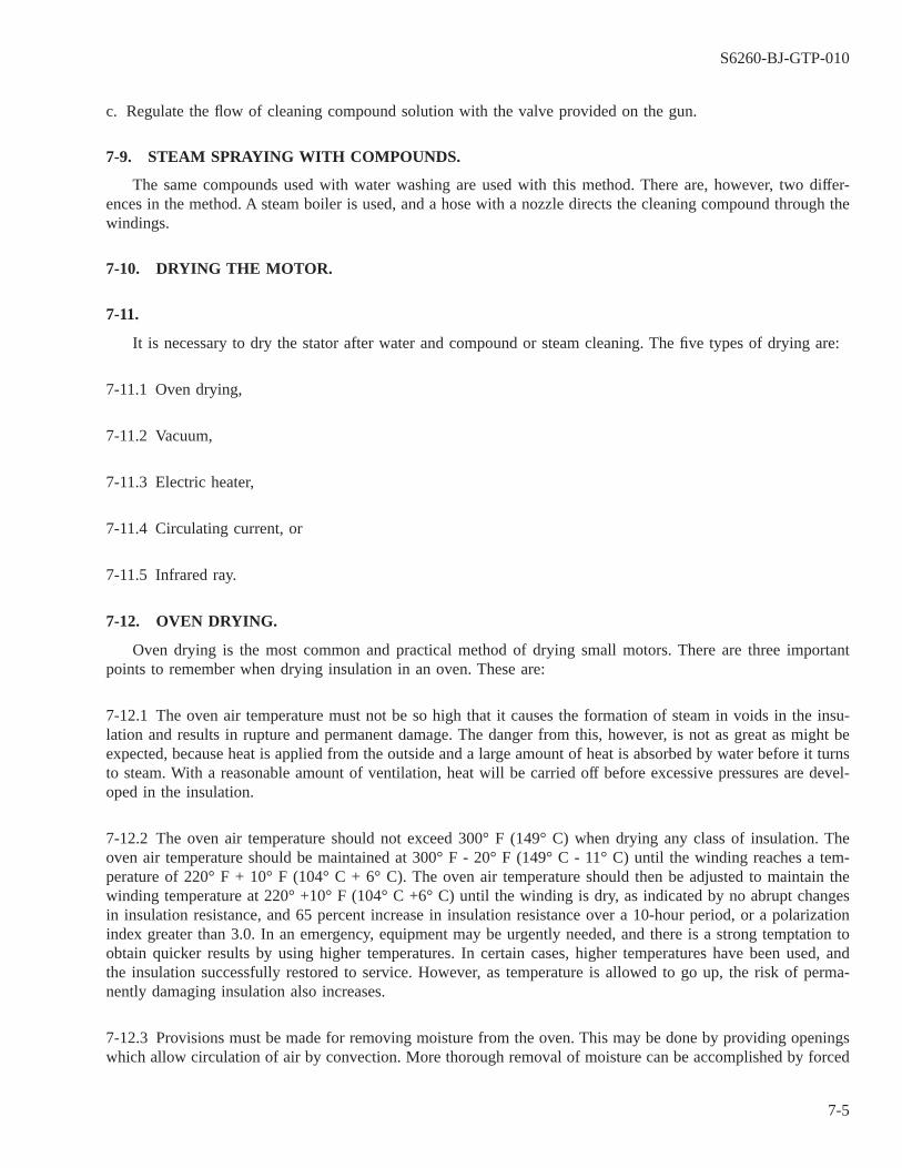
c. Regulate the flow of cleaning compound solution with the valve provided on the gun.
7-9. STEAM SPRAYING WITH COMPOUNDS.
The same compounds used with water washing are used with this method. There are, however, two differ-ences in the method. A steam boiler is used, and a hose with a nozzle directs the cleaning compound through thewindings.
7-10. DRYING THE MOTOR.
7-11.
It is necessary to dry the stator after water and compound or steam cleaning. The five types of drying are:
7-11.1 Oven drying,
7-11.2 Vacuum,
7-11.3 Electric heater,
7-11.4 Circulating current, or
7-11.5 Infrared ray.
7-12. OVEN DRYING.
Oven drying is the most common and practical method of drying small motors. There are three importantpoints to remember when drying insulation in an oven. These are:
7-12.1 The oven air temperature must not be so high that it causes the formation of steam in voids in the insu-lation and results in rupture and permanent damage. The danger from this, however, is not as great as might beexpected, because heat is applied from the outside and a large amount of heat is absorbed by water before it turnsto steam. With a reasonable amount of ventilation, heat will be carried off before excessive pressures are devel-oped in the insulation.
7-12.2 The oven air temperature should not exceed 300° F (149° C) when drying any class of insulation. Theoven air temperature should be maintained at 300° F - 20° F (149° C - 11° C) until the winding reaches a tem-perature of 220° F + 10° F (104° C + 6° C). The oven air temperature should then be adjusted to maintain thewinding temperature at 220° +10° F (104° C +6° C) until the winding is dry, as indicated by no abrupt changesin insulation resistance, and 65 percent increase in insulation resistance over a 10-hour period, or a polarizationindex greater than 3.0. In an emergency, equipment may be urgently needed, and there is a strong temptation toobtain quicker results by using higher temperatures. In certain cases, higher temperatures have been used, andthe insulation successfully restored to service. However, as temperature is allowed to go up, the risk of perma-nently damaging insulation also increases.
7-12.3 Provisions must be made for removing moisture from the oven. This may be done by providing openingswhich allow circulation of air by convection. More thorough removal of moisture can be accomplished by forced
S6260-BJ-GTP-010
7-5
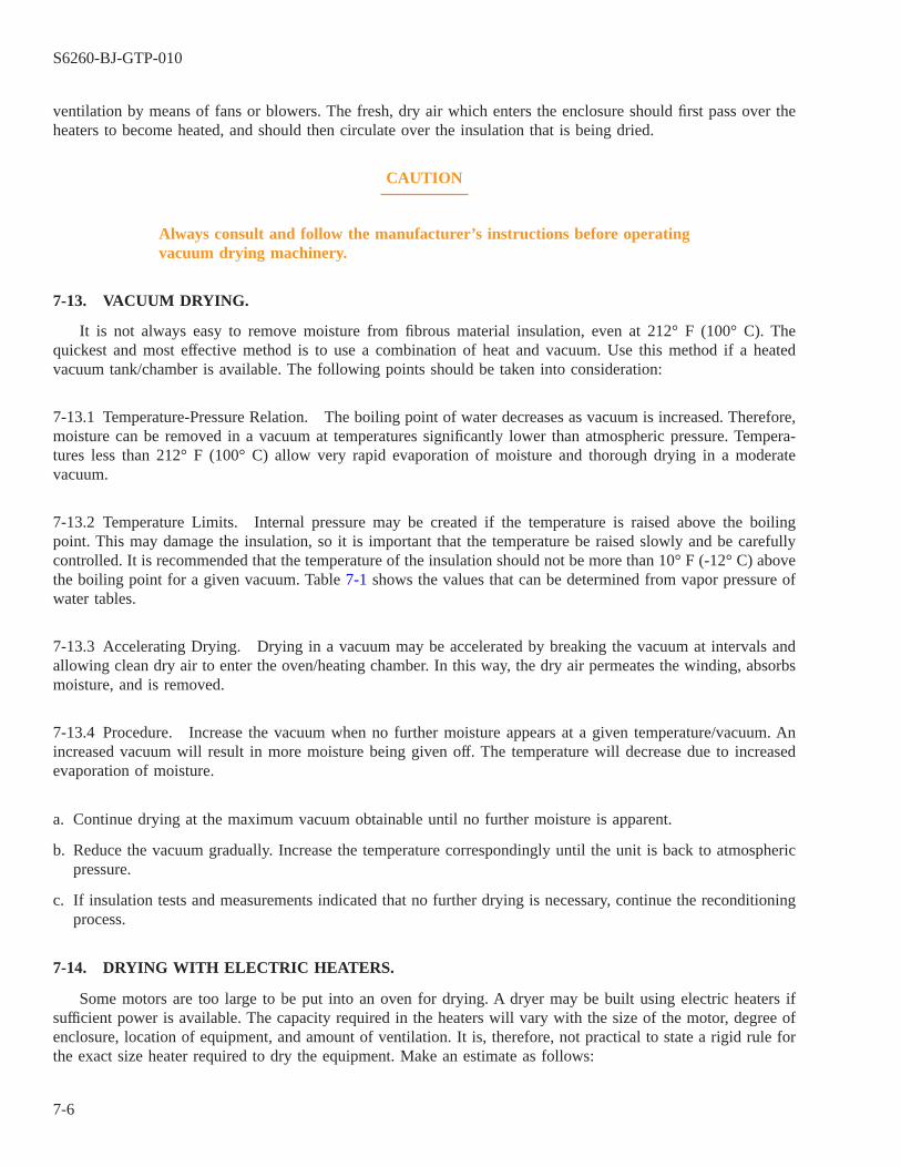
ventilation by means of fans or blowers. The fresh, dry air which enters the enclosure should first pass over theheaters to become heated, and should then circulate over the insulation that is being dried.
CAUTION
Always consult and follow the manufacturer’s instructions before operatingvacuum drying machinery.
7-13. VACUUM DRYING.
It is not always easy to remove moisture from fibrous material insulation, even at 212° F (100° C). Thequickest and most effective method is to use a combination of heat and vacuum. Use this method if a heatedvacuum tank/chamber is available. The following points should be taken into consideration:
7-13.1 Temperature-Pressure Relation. The boiling point of water decreases as vacuum is increased. Therefore,moisture can be removed in a vacuum at temperatures significantly lower than atmospheric pressure. Tempera-tures less than 212° F (100° C) allow very rapid evaporation of moisture and thorough drying in a moderatevacuum.
7-13.2 Temperature Limits. Internal pressure may be created if the temperature is raised above the boilingpoint. This may damage the insulation, so it is important that the temperature be raised slowly and be carefullycontrolled. It is recommended that the temperature of the insulation should not be more than 10° F (-12° C) abovethe boiling point for a given vacuum. Table 7-1 shows the values that can be determined from vapor pressure ofwater tables.
7-13.3 Accelerating Drying. Drying in a vacuum may be accelerated by breaking the vacuum at intervals andallowing clean dry air to enter the oven/heating chamber. In this way, the dry air permeates the winding, absorbsmoisture, and is removed.
7-13.4 Procedure. Increase the vacuum when no further moisture appears at a given temperature/vacuum. Anincreased vacuum will result in more moisture being given off. The temperature will decrease due to increasedevaporation of moisture.
a. Continue drying at the maximum vacuum obtainable until no further moisture is apparent.
b. Reduce the vacuum gradually. Increase the temperature correspondingly until the unit is back to atmosphericpressure.
c. If insulation tests and measurements indicated that no further drying is necessary, continue the reconditioningprocess.
7-14. DRYING WITH ELECTRIC HEATERS.
Some motors are too large to be put into an oven for drying. A dryer may be built using electric heaters ifsufficient power is available. The capacity required in the heaters will vary with the size of the motor, degree ofenclosure, location of equipment, and amount of ventilation. It is, therefore, not practical to state a rigid rule forthe exact size heater required to dry the equipment. Make an estimate as follows:
S6260-BJ-GTP-010
7-6
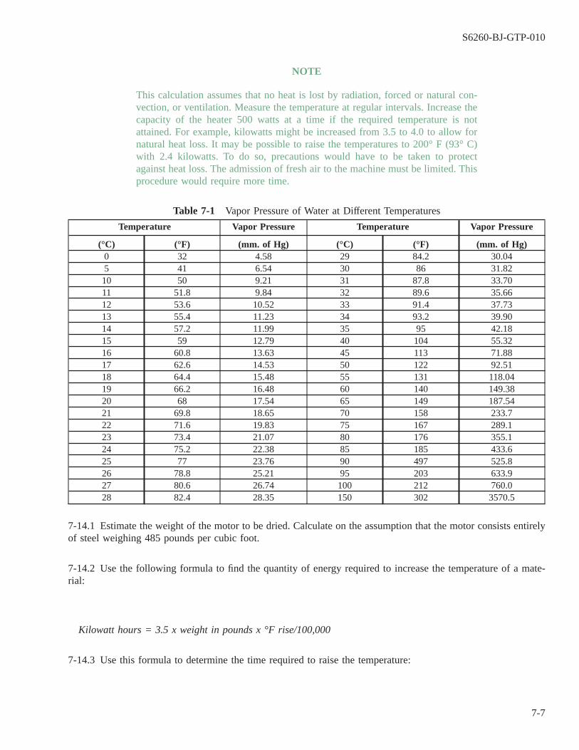
NOTE
This calculation assumes that no heat is lost by radiation, forced or natural con-vection, or ventilation. Measure the temperature at regular intervals. Increase thecapacity of the heater 500 watts at a time if the required temperature is notattained. For example, kilowatts might be increased from 3.5 to 4.0 to allow fornatural heat loss. It may be possible to raise the temperatures to 200° F (93° C)with 2.4 kilowatts. To do so, precautions would have to be taken to protectagainst heat loss. The admission of fresh air to the machine must be limited. Thisprocedure would require more time.
Table 7-1 Vapor Pressure of Water at Different Temperatures
Temperature Vapor Pressure Temperature Vapor Pressure
(°C) (°F) (mm. of Hg) (°C) (°F) (mm. of Hg)0 32 4.58 29 84.2 30.045 41 6.54 30 86 31.8210 50 9.21 31 87.8 33.7011 51.8 9.84 32 89.6 35.6612 53.6 10.52 33 91.4 37.7313 55.4 11.23 34 93.2 39.9014 57.2 11.99 35 95 42.1815 59 12.79 40 104 55.3216 60.8 13.63 45 113 71.8817 62.6 14.53 50 122 92.5118 64.4 15.48 55 131 118.0419 66.2 16.48 60 140 149.3820 68 17.54 65 149 187.5421 69.8 18.65 70 158 233.722 71.6 19.83 75 167 289.123 73.4 21.07 80 176 355.124 75.2 22.38 85 185 433.625 77 23.76 90 497 525.826 78.8 25.21 95 203 633.927 80.6 26.74 100 212 760.028 82.4 28.35 150 302 3570.5
7-14.1 Estimate the weight of the motor to be dried. Calculate on the assumption that the motor consists entirelyof steel weighing 485 pounds per cubic foot.
7-14.2 Use the following formula to find the quantity of energy required to increase the temperature of a mate-rial:
Kilowatt hours = 3.5 x weight in pounds x °F rise/100,000
7-14.3 Use this formula to determine the time required to raise the temperature:
S6260-BJ-GTP-010
7-7
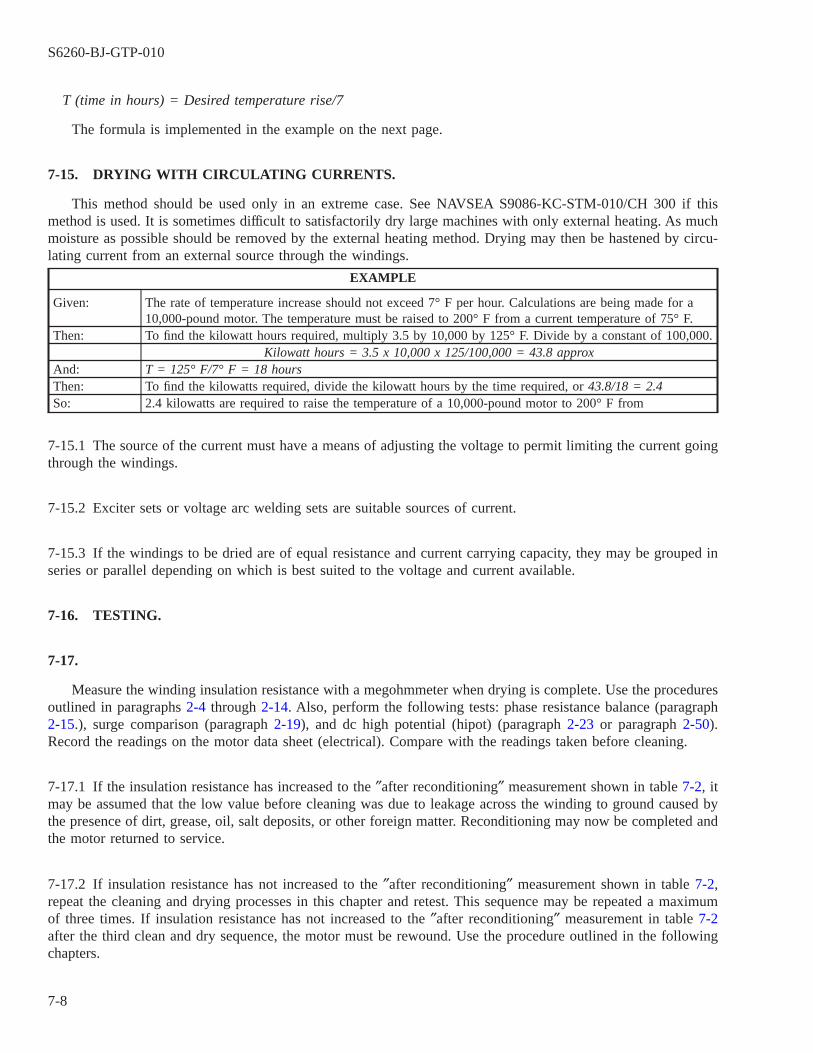
T (time in hours) = Desired temperature rise/7
The formula is implemented in the example on the next page.
7-15. DRYING WITH CIRCULATING CURRENTS.
This method should be used only in an extreme case. See NAVSEA S9086-KC-STM-010/CH 300 if thismethod is used. It is sometimes difficult to satisfactorily dry large machines with only external heating. As muchmoisture as possible should be removed by the external heating method. Drying may then be hastened by circu-lating current from an external source through the windings.
EXAMPLE
Given: The rate of temperature increase should not exceed 7° F per hour. Calculations are being made for a10,000-pound motor. The temperature must be raised to 200° F from a current temperature of 75° F.
Then: To find the kilowatt hours required, multiply 3.5 by 10,000 by 125° F. Divide by a constant of 100,000.Kilowatt hours = 3.5 x 10,000 x 125/100,000 = 43.8 approx
And: T = 125° F/7° F = 18 hoursThen: To find the kilowatts required, divide the kilowatt hours by the time required, or 43.8/18 = 2.4So: 2.4 kilowatts are required to raise the temperature of a 10,000-pound motor to 200° F from
7-15.1 The source of the current must have a means of adjusting the voltage to permit limiting the current goingthrough the windings.
7-15.2 Exciter sets or voltage arc welding sets are suitable sources of current.
7-15.3 If the windings to be dried are of equal resistance and current carrying capacity, they may be grouped inseries or parallel depending on which is best suited to the voltage and current available.
7-16. TESTING.
7-17.
Measure the winding insulation resistance with a megohmmeter when drying is complete. Use the proceduresoutlined in paragraphs 2-4 through 2-14. Also, perform the following tests: phase resistance balance (paragraph2-15.), surge comparison (paragraph 2-19), and dc high potential (hipot) (paragraph 2-23 or paragraph 2-50).Record the readings on the motor data sheet (electrical). Compare with the readings taken before cleaning.
7-17.1 If the insulation resistance has increased to the ″after reconditioning″ measurement shown in table 7-2, itmay be assumed that the low value before cleaning was due to leakage across the winding to ground caused bythe presence of dirt, grease, oil, salt deposits, or other foreign matter. Reconditioning may now be completed andthe motor returned to service.
7-17.2 If insulation resistance has not increased to the ″after reconditioning″ measurement shown in table 7-2,repeat the cleaning and drying processes in this chapter and retest. This sequence may be repeated a maximumof three times. If insulation resistance has not increased to the ″after reconditioning″ measurement in table 7-2after the third clean and dry sequence, the motor must be rewound. Use the procedure outlined in the followingchapters.
S6260-BJ-GTP-010
7-8

NOTE
For dipping and baking, refer to Chapter 10, and for final electrical testing, referto Chapter 11.
7-18. CLEANING ELECTRICAL EQUIPMENT AFTER SEAWATER DAMAGE.
7-19. IMPORTANCE OF THOROUGH CLEANING.
Electrical equipment may be damaged by being submerged in or splashed with seawater. Reliability isimperative in electrical equipment. Therefore, such equipment must be restored as nearly as possible to new con-dition.
NOTE
Sodium chloride is the principle salt found in seawater. Magnesium chloride andcalcium chloride are also present, but in lesser amounts. All salts have a corro-sive effect on metals. It is important, therefore, that all traces of seawater and saltdeposits be thoroughly removed before equipment is returned to service.
Table 7-2 Insulation Resistance for Generators and Motors
AC GENERATORS AND MOTORS OTHER THAN PROPULSION
Insulation Resistance (megohms at 25°C) 1
Circuit Minimum forOperation
After Cleaning inShip
After Recndtn AfterRewinding
Stator circuit of generators and motors 0.2 1.0 25 200Rotor circuit of wound rotor induction motors 0.1 0.5 25 100Field circuit of generators or of synchronousmotors
0.4 2.0 25 400
Stator circuit of motors with sealed insulationsystem
0.2 25 500 1000 2
100 3
DC GENERATORS AND MOTORS (EXCEPT PROPULSION AND AUXILIARY GENERATORS FOR SUB-MARINES) INCLUDING EXCITERS
Insulation Resistance (megohms at 25° C) 1
Circuit Minimum forOperation
After Cleaning inShip
After Recndtn AfterRewinding
Complete armature circuit 2 , a 0.1 0.5 1.0 100Armature alone 0.2 1.0 2.0 200Armature circuit less armature 2 , b 0.2 1.0 2.0 200Complete field circuit 0.5 1.5 2.5 200
S6260-BJ-GTP-010
7-9

1Values are for machines rated 500 volts or less. For machines having a rated voltage (E) greater than 500 volts,multiply all values given in the table by E/500.
2Minimum acceptable value with winding dry, before and after submergence test.
3Minimum acceptable value during 24-hour fresh water submergence test.
1Values are for machines rated 250 volts or less. For machines having a rated voltage (E) greater than 250 volts,multiply all values given in the table by E/250.
2Small machines usually have one of the shunt field leads connected internally to the armature circuit. To avoiddisassembly in such cases, the complete armature circuit and the complete field circuit may be measured with-out breaking this connection. If necessary, the armature can be isolated by lifting the brushes.
aWith brushes left in place, the complete armature circuit will include armature, armature circuit, and the perma-nent connected field circuit. The values given in the table for the complete armature circuit will apply.
bWith brushes lifted, the armature circuit, less armature and the complete field circuit, will be measured. The val-ues given in the table for armature circuit, less armature, will apply.
7-20. CLEANING.
Follow these steps in cleaning equipment after seawater exposure.
a. Thoroughly flush all salt deposits from the windings. Use the methods presented in paragraph 7-7 or paragraph7-8.
b. As the washing progresses, collect drippings. Test these drippings by one of the following means:
(1) Obtain competent technical assistance to perform the standard salinity test, or
(2) Take 2 ounces of drip test water. Add 2 to 3 drops dilute nitric acid and 2 drops of silver nitrate. If thesolution becomes clouded, the amount of clouding indicates the amount of salts still present.
c. Continue washing and flushing for 1 hour after test water runs clear. This ensures thorough cleaning.
d. For drying after cleaning, use the methods described in paragraphs 7-10 through 7-15.
e. If time and conditions permit, use the following method to assure reliability of the equipment:
(1) Measure the insulation resistance while the unit is still hot from the drying process. Continue to measureat frequent intervals as it cools to room temperature.
(2) Allow the unit to stand for 2 days or longer after cooling. Keep the humidity as high as possible, usingpans of water placed on heating coils if necessary.
(3) Measure the insulation resistance frequently. If possible, let a reconditioned motor that has not been sub-jected to salt water stand in the same area. Compare the insulation readings.
(4) Insulation readings should not fall rapidly under these conditions. Readings should not be significantlylower than those of the other motor. If they do fall, or are lower, the salt has not been completely removed.The motor should be washed and dried again before proceeding further.
S6260-BJ-GTP-010
7-10

WARNING
Rust preventive compound may produce dizziness if adequate ventilation isnot provided.
CAUTION
This product may have a corrosive effect on paint, varnish, and insulation.Keep it clear of windings and fabric insulation.
f. Rust prevention measures must be taken as soon as possible on all components. Apply rust preventive after allmetal parts have been thoroughly washed and dried. Use a suitable compound such as MIL-C-16173, com-pound, rust preventive, grade 3, thin film (Polar type) (NSN 8030-00-244-1296, 1 gallon; 8030-00-244-1293,5 gallons; 8030-00-244-1294, 55 gallons). Apply it to all metallic parts which are subject to corrosion. Thiscompound displaces water and prevents rust.
7-21.
If the previous cleaning methods failed to correct the problem, the following actions must be taken:
7-21.1 In order to obtain maximum reliability, all coils and windings should be replaced if electrical equipmenthas been submerged in seawater.
7-21.2 All laminated steel magnet core structures should be replaced. Complete salt removal from these compo-nents is practically impossible.
7-22. CLEANING MOTORS WITH SOLVENTS.
WARNING
Solvents must be used with extreme care while following all applicable safetyprecautions for the type of solvent used. Most solvents are toxic and can beharmful to personnel if vapors are breathed or if the liquid comes into con-tact with the skin. Solvents should not be used where contact with openflame or extremely hot surfaces might occur because of the danger of fire orthe generation of toxic fumes. Proper personnel protective equipment mustbe worn and adequate ventilation provided whenever solvents are used.Refer to NAVSEA S9086-KC-STM-010/CH 300 for the names of approvedsolvents, methods of use, and safety precautions required.
7-23.
Avoid the use of solvents for motor cleaning if possible. Use solvent cleaning only when other cleaningmethods will not do.
S6260-BJ-GTP-010
7-11

7-24. DRY CLEANING SOLVENT, TYPE II.
WARNING
This solvent is highly flammable. Its use requires the strictest observance ofall safety precautions pertaining to open flames, smoking, or spark produc-ing activity.
CAUTION
Dry cleaning solvent type II, P-D-680 (NSN 6850-00-274-5421), may be dam-aging to some types of insulation. A test should be made to a small spotbefore using.
7-24.1 The cleaning efficiency as well as the ill effects to personnel are less than the chlorinated solvents.
a. Apply solvent to a small area of stator windings by use of a moistened, lint-free cloth. Examine area to if anyadverse effects have occurred.
b. Continue to wipe the windings if no adverse effects are noted. Wipe dry with a clean, lint-free cloth.
c. Repeat wiping and drying steps as necessary.
S6260-BJ-GTP-010
7-12

CHAPTER 8
BURNOUT AND STRIPPING PROCEDURES
8-1. SCOPE.
This chapter outlines the procedures used to burn out, strip, and prepare a stator for rewinding. Topicsinclude:
8-1.1 Winding identification and data collection (paragraph 8-2).
8-1.2 Oven burnout and stripping (paragraph 8-12).
8-1.3 Stripping a stator by warming and pulling (paragraph 8-16).
8-1.4 Stator cleanup (paragraph 8-22).
8-1.5 Stator sealing or varnishing (paragraph 8-30).
8-2. WINDING IDENTIFICATION AND DATA COLLECTION.
8-3.
A motor winding must be correctly identified before replacement. All pertinent information must be recordedbefore any connections are broken and the winding destroyed. The repaired motor cannot function properly if thewinding has been changed or modified.
8-4. DATA COLLECTION FROM MASTER DRAWINGS.
The master drawing of the stator to be rewound is the primary source of rewind data. The master drawingincludes all information necessary to rewind the stator. The winding information contained in the master draw-ing should be verified. If the information in the master drawing does not match the existing winding, properwinding data can be verified by contacting the Naval Sea Systems Command, Code 03Z71.
8-5. DATA COLLECTION FROM OLD WINDINGS.
Information can be obtained from the old winding if the master drawing is not available. If the winding isnot encapsulated (see Appendix E for identification of encapsulated windings), it may be possible to obtain mostof the required information as described in paragraphs 8-6 through 8-11.
8-6. NECESSARY INFORMATION.
The characteristics of the following are required for rewinding the stator:
8-6.1 Coil winding,
8-6.2 Pole phase groups,
8-6.3 Coil sides per slot, and
S6260-BJ-GTP-010
8-1

8-6.4 Lead wires and connectors.
8-7. MOTOR REPAIR IDENTIFICATION SHEET.
All winding information should be recorded on the motor repair identification sheet (figure 8-1). The top andnameplate sections of the sheet are self-explanatory. Paragraphs 8-8 through 8-11 refer to the winding section.Take as much data as possible before the winding is cut.
8-8. COIL WINDING.
The following information is necessary to determine the coil winding:
8-8.1 Coil Shape. The coil will usually be round-nosed, flat-nosed, or diamond shaped. Determine the shapeby visual inspection. See figure 9-1 in Chapter 9.
8-8.2 Coil Span. Coil span or pitch corresponds to the number of slots separating the sides of a coil. The spanincludes the slots in which the coil lies. These data are taken when the coils are being stripped out of the motor.
NOTE
Insulation must be stripped from the wire before it is measured.
8-8.3 Wire Size. Pull out the lead wire, Cut it below the soldered connection. Measure the magnet wire witha wire gage. Conductor size is determined by the area of the copper conductor used to wind the stator. The con-ductor may be round, rectangular, or square. Most conductors used in random-wound U.S. Navy motors areround. In order to fully utilize the slot area, there may be more than one conductor in a coil. In that case, thereare parallel paths or conductors in parallel in the coil. More than one size of conductor may also be used in acoil.
8-8.4 Number of Wires in Hand. Determine the number of wires in hand (conductors in parallel) by countingthe wires in one group going to a lead wire. When more than one group connects to a lead wire, be sure to pickup the leads of only one group.
8-8.5 Turns per Coil. Determine the number of turns per coil by counting the conductors in a complete coil.Divide the conductors by the number of wires in hand (conductors in parallel) to determine turns per coil.Recover at least one complete coil so that the turns can be counted. Record the number of turns on the motorrepair identification sheet (figure 8-1).
8-8.6 End Room. End room is the distance the coils protrude beyond the ends of the slots. Use a rule to mea-sure the distance from the end of the laminations to the end of the winding.
S6260-BJ-GTP-010
8-2

8-9. POLE PHASE GROUPS.
The following information is necessary to determine pole phase groups:
Figure 8-1 Motor Repair Identification Sheet
S6260-BJ-GTP-010
8-3

8-9.1 Number of Poles. The number of poles and the frequency of the motor will determine the speed of rota-tion of the motor rotor. Repair personnel must determine the number of poles in a motor to be able to completethe motor repair identification sheet (figure 8-1). The number of poles in a motor will be some number times two(north and south poles). The number of poles in a motor can be determined by the following formula:
P = 7200/N, where P = poles and N = motor speed
Example: P = 7200/N = 7200/3550 = 2.03 pole motor
There cannot be a fraction of a pole. Drop the decimal 0.03 and the motor is a two-pole motor. After gain-ing some experience, repair personnel will be able to recognize the speeds of various pole combinations withoutperforming calculations. See table 8-1 for determining motor speed by comparison.
8-9.2 Pole Phase Groups. Use the number of poles determined in paragraph 8-9.1 to determine the number ofpole phase groups in the motor. The number of phases for which the motor is designed will be on the nameplateof the motor.
PPG = P x Ø, where
PPG = Pole phase groups
P = Number of poles determined using paragraph 8-9.1.
Ø = Phases for which the motor is designed
The number of pole phase groups calculated in this manner determines the number of groups of coils neededto wind a motor. Repair personnel will also need the number of pole phase groups to determine the coils to bewound in a group or to determine the coils to be connected together to make a pole phase group.
Table 8-1 Motor Speed Table
Operating Speed Synchronous Speed Poles
3450 - 3575 3600 21725 - 1775 1800 41150 - 1175 1200 6825 - 875 900 8675 - 690 720 10500 - 575 600 12
8-9.3 Number of Coils per Group. Individual coils are wound together or connected to form a pole phasegroup. To determine the number of coils in one pole phase group for a distributed winding (two coil sides perslot in a single winding):
S6260-BJ-GTP-010
8-4
An active coil is a coil that is electrically connected in the stator circuit (Total active coils = Active coils perphase x Number of phases).
8-10. COIL SIDES PER SLOT.
The following information is necessary to determine coil sides per slot:
8-10.1 Number of Slots. Count the number of slots in the stator.
8-10.2 Coil Sides per Slot. Examine the stator and determine the number of coil sides per slot. Basket wind-ings (concentric windings) will usually have only one coil side per slot for each winding, as shown in figure8-2(A). Some variations of this winding may have two coil sides per slot. When winding a basket winding, bothsides of each coil are put into the slots of the stator at the same time. Do this from the beginning of the wind-ing (bottom to bottom or top to top). The winding appears as a basket weave when viewed from the top. Distrib-uted windings, also called whole coil or lap windings, have the winding laid in with one coil side in the bottomof one slot and the other coil side in the top of a slot. The end of the winding has a smooth or distributed appear-ance when viewed from the top. The coils appear to lay in each other on the ends (figure 8-2(B)).
S6260-BJ-GTP-010
8-5

8-11. LEAD WIRES AND CONNECTIONS.
The following information is necessary to determine lead wires and connections:
Figure 8-2 Portions of Distributed and Basket Windings
S6260-BJ-GTP-010
8-6

8-11.1 Lead Wire Size. Measure the lead wire. The lead wire size may be checked against a lead wire table toensure that the proper size is being used (table 8-2).
8-11.2 Type of Connection. There are basically two types of connections: delta and wye. In both cases, the typeof connection is determined by examining how the leads are connected together. In the wye connection, three ofthe beginning or ending leads will be connected at a single neutral point in the form of the letter Y . In the deltaconnection, there will be three connecting points, each with two leads, each point being in the form of a δ. (SeeAppendix D, paragraph D-17, for further details and illustrations.) Use the steps below in determining the typeof connection:
Table 8-2 Lead Wire Table for Motors
H.P. Wye Delta
220 V 440 V 220 V 440 V3 Lead 3 or 9 Lead 3 Lead 3 or 9 Lead 2300 V 4160 V
1-2-3 4-5-6-7-8-91 16 16 16 16
2 16 16 16 16 163 16 16 16 16 165 14 14 14 14 14
7.5 12 14 12 14 1410 10 12 10 12 1215 10 12 10 12 1220 8 10 8 10 1025 6 10 6 10 1030 6 8 6 10 1040 4 8 4 8 1050 2 6 2 6 1060 2 6 2 6 8 Up to Up to75 0 4 0 4 6100 2/0 2 2/0 2 4125 3/0 2 4/0 2 4150 2#1 0 2#1 0 2200 2#2/0 2/0 2#2/0 2/0 1250 2#3/0 3/0 2#3/0 3/0 2/0 #8300 2#1 2#1 #3350 2#2/0 2#2/0 #3400 2#2/0 2#2/0 #3450 2#3/0 2#3/0 #3500 2#3/0 2#3/0 #3 #8
NOTE
Lead wire connections can also be examined to determine whether the connec-tion is a delta or wye connection. A wye connection would be designated as asingle coil connected to the lead wire. A delta connection is determined if twocoils connect to the lead wire.
a. Cut the tie cords on the connection end.
S6260-BJ-GTP-010
8-7
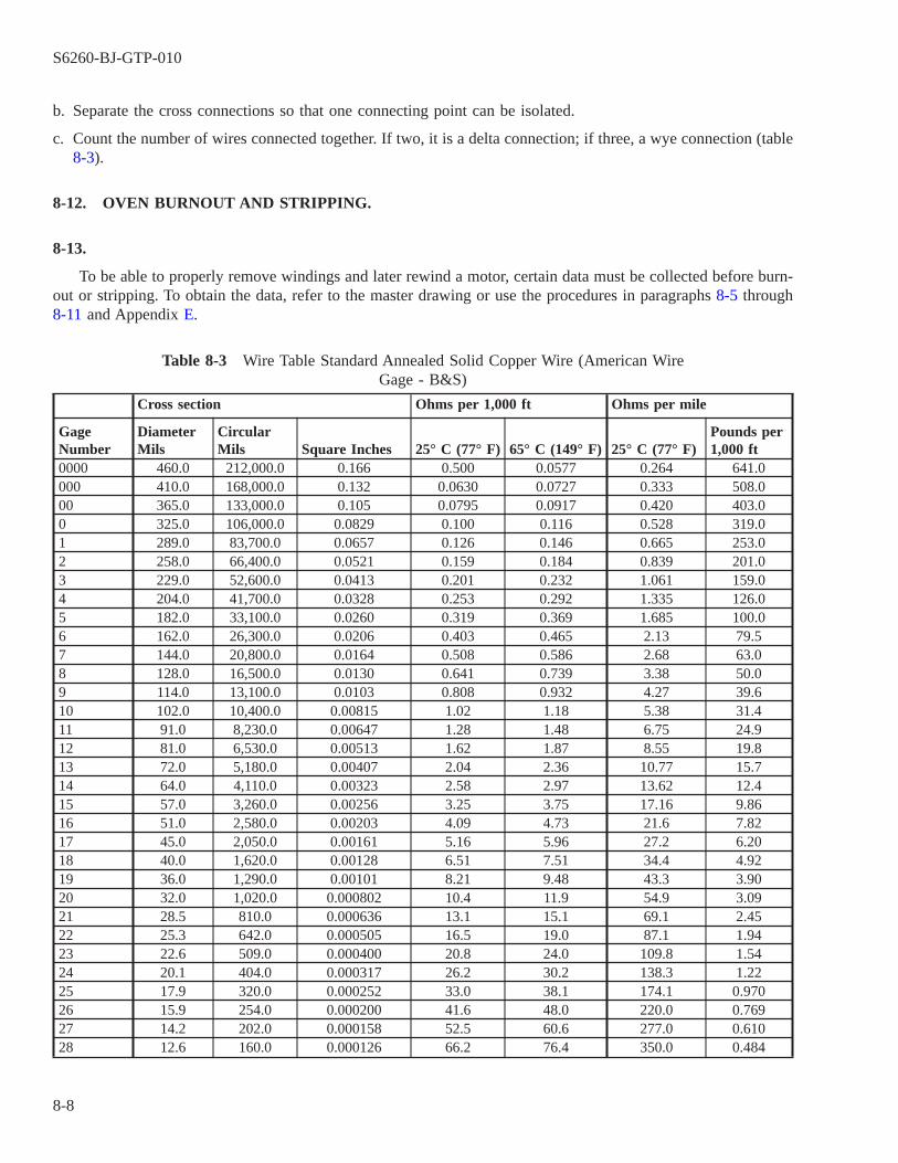
b. Separate the cross connections so that one connecting point can be isolated.
c. Count the number of wires connected together. If two, it is a delta connection; if three, a wye connection (table8-3).
8-12. OVEN BURNOUT AND STRIPPING.
8-13.
To be able to properly remove windings and later rewind a motor, certain data must be collected before burn-out or stripping. To obtain the data, refer to the master drawing or use the procedures in paragraphs 8-5 through8-11 and Appendix E.
Table 8-3 Wire Table Standard Annealed Solid Copper Wire (American WireGage - B&S)
Cross section Ohms per 1,000 ft Ohms per mile
GageNumber
DiameterMils
CircularMils Square Inches 25° C (77° F) 65° C (149° F) 25° C (77° F)
Pounds per1,000 ft
0000 460.0 212,000.0 0.166 0.500 0.0577 0.264 641.0000 410.0 168,000.0 0.132 0.0630 0.0727 0.333 508.000 365.0 133,000.0 0.105 0.0795 0.0917 0.420 403.00 325.0 106,000.0 0.0829 0.100 0.116 0.528 319.01 289.0 83,700.0 0.0657 0.126 0.146 0.665 253.02 258.0 66,400.0 0.0521 0.159 0.184 0.839 201.03 229.0 52,600.0 0.0413 0.201 0.232 1.061 159.04 204.0 41,700.0 0.0328 0.253 0.292 1.335 126.05 182.0 33,100.0 0.0260 0.319 0.369 1.685 100.06 162.0 26,300.0 0.0206 0.403 0.465 2.13 79.57 144.0 20,800.0 0.0164 0.508 0.586 2.68 63.08 128.0 16,500.0 0.0130 0.641 0.739 3.38 50.09 114.0 13,100.0 0.0103 0.808 0.932 4.27 39.610 102.0 10,400.0 0.00815 1.02 1.18 5.38 31.411 91.0 8,230.0 0.00647 1.28 1.48 6.75 24.912 81.0 6,530.0 0.00513 1.62 1.87 8.55 19.813 72.0 5,180.0 0.00407 2.04 2.36 10.77 15.714 64.0 4,110.0 0.00323 2.58 2.97 13.62 12.415 57.0 3,260.0 0.00256 3.25 3.75 17.16 9.8616 51.0 2,580.0 0.00203 4.09 4.73 21.6 7.8217 45.0 2,050.0 0.00161 5.16 5.96 27.2 6.2018 40.0 1,620.0 0.00128 6.51 7.51 34.4 4.9219 36.0 1,290.0 0.00101 8.21 9.48 43.3 3.9020 32.0 1,020.0 0.000802 10.4 11.9 54.9 3.0921 28.5 810.0 0.000636 13.1 15.1 69.1 2.4522 25.3 642.0 0.000505 16.5 19.0 87.1 1.9423 22.6 509.0 0.000400 20.8 24.0 109.8 1.5424 20.1 404.0 0.000317 26.2 30.2 138.3 1.2225 17.9 320.0 0.000252 33.0 38.1 174.1 0.97026 15.9 254.0 0.000200 41.6 48.0 220.0 0.76927 14.2 202.0 0.000158 52.5 60.6 277.0 0.61028 12.6 160.0 0.000126 66.2 76.4 350.0 0.484
S6260-BJ-GTP-010
8-8
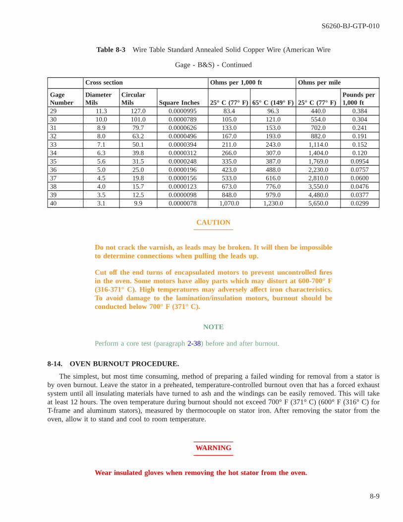
Table 8-3 Wire Table Standard Annealed Solid Copper Wire (American Wire
Gage - B&S) - Continued
Cross section Ohms per 1,000 ft Ohms per mile
GageNumber
DiameterMils
CircularMils Square Inches 25° C (77° F) 65° C (149° F) 25° C (77° F)
Pounds per1,000 ft
29 11.3 127.0 0.0000995 83.4 96.3 440.0 0.38430 10.0 101.0 0.0000789 105.0 121.0 554.0 0.30431 8.9 79.7 0.0000626 133.0 153.0 702.0 0.24132 8.0 63.2 0.0000496 167.0 193.0 882.0 0.19133 7.1 50.1 0.0000394 211.0 243.0 1,114.0 0.15234 6.3 39.8 0.0000312 266.0 307.0 1,404.0 0.12035 5.6 31.5 0.0000248 335.0 387.0 1,769.0 0.095436 5.0 25.0 0.0000196 423.0 488.0 2,230.0 0.075737 4.5 19.8 0.0000156 533.0 616.0 2,810.0 0.060038 4.0 15.7 0.0000123 673.0 776.0 3,550.0 0.047639 3.5 12.5 0.0000098 848.0 979.0 4,480.0 0.037740 3.1 9.9 0.0000078 1,070.0 1,230.0 5,650.0 0.0299
CAUTION
Do not crack the varnish, as leads may be broken. It will then be impossibleto determine connections when pulling the leads up.
Cut off the end turns of encapsulated motors to prevent uncontrolled firesin the oven. Some motors have alloy parts which may distort at 600-700° F(316-371° C). High temperatures may adversely affect iron characteristics.To avoid damage to the lamination/insulation motors, burnout should beconducted below 700° F (371° C).
NOTE
Perform a core test (paragraph 2-38) before and after burnout.
8-14. OVEN BURNOUT PROCEDURE.
The simplest, but most time consuming, method of preparing a failed winding for removal from a stator isby oven burnout. Leave the stator in a preheated, temperature-controlled burnout oven that has a forced exhaustsystem until all insulating materials have turned to ash and the windings can be easily removed. This will takeat least 12 hours. The oven temperature during burnout should not exceed 700° F (371° C) (600° F (316° C) forT-frame and aluminum stators), measured by thermocouple on stator iron. After removing the stator from theoven, allow it to stand and cool to room temperature.
WARNING
Wear insulated gloves when removing the hot stator from the oven.
S6260-BJ-GTP-010
8-9
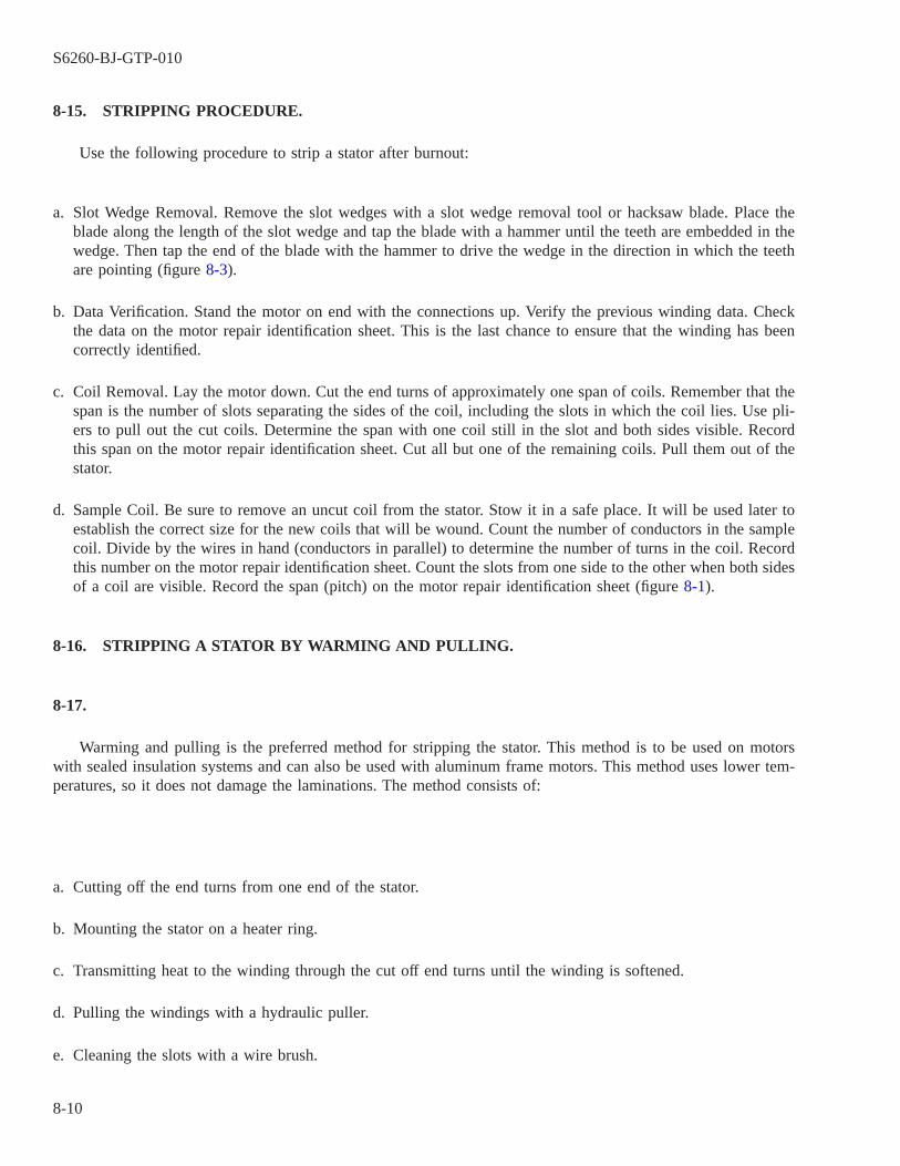
8-15. STRIPPING PROCEDURE.
Use the following procedure to strip a stator after burnout:
a. Slot Wedge Removal. Remove the slot wedges with a slot wedge removal tool or hacksaw blade. Place theblade along the length of the slot wedge and tap the blade with a hammer until the teeth are embedded in thewedge. Then tap the end of the blade with the hammer to drive the wedge in the direction in which the teethare pointing (figure 8-3).
b. Data Verification. Stand the motor on end with the connections up. Verify the previous winding data. Checkthe data on the motor repair identification sheet. This is the last chance to ensure that the winding has beencorrectly identified.
c. Coil Removal. Lay the motor down. Cut the end turns of approximately one span of coils. Remember that thespan is the number of slots separating the sides of the coil, including the slots in which the coil lies. Use pli-ers to pull out the cut coils. Determine the span with one coil still in the slot and both sides visible. Recordthis span on the motor repair identification sheet. Cut all but one of the remaining coils. Pull them out of thestator.
d. Sample Coil. Be sure to remove an uncut coil from the stator. Stow it in a safe place. It will be used later toestablish the correct size for the new coils that will be wound. Count the number of conductors in the samplecoil. Divide by the wires in hand (conductors in parallel) to determine the number of turns in the coil. Recordthis number on the motor repair identification sheet. Count the slots from one side to the other when both sidesof a coil are visible. Record the span (pitch) on the motor repair identification sheet (figure 8-1).
8-16. STRIPPING A STATOR BY WARMING AND PULLING.
8-17.
Warming and pulling is the preferred method for stripping the stator. This method is to be used on motorswith sealed insulation systems and can also be used with aluminum frame motors. This method uses lower tem-peratures, so it does not damage the laminations. The method consists of:
a. Cutting off the end turns from one end of the stator.
b. Mounting the stator on a heater ring.
c. Transmitting heat to the winding through the cut off end turns until the winding is softened.
d. Pulling the windings with a hydraulic puller.
e. Cleaning the slots with a wire brush.
S6260-BJ-GTP-010
8-10
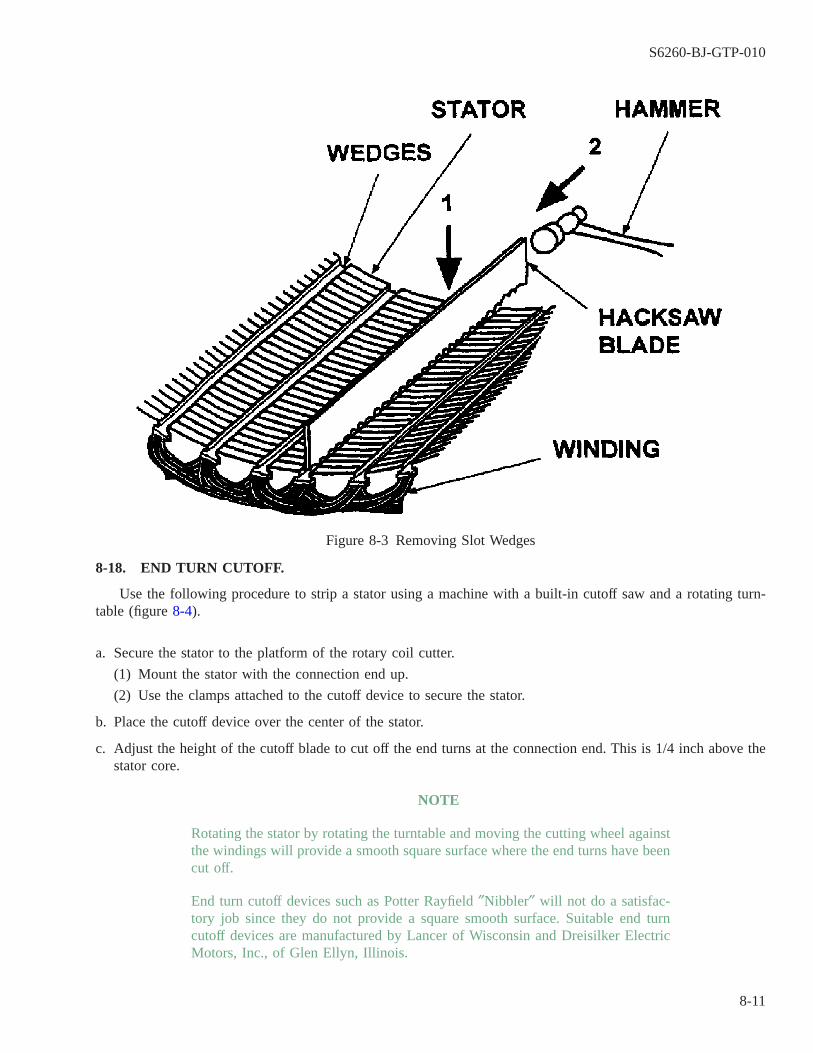
8-18. END TURN CUTOFF.
Use the following procedure to strip a stator using a machine with a built-in cutoff saw and a rotating turn-table (figure 8-4).
a. Secure the stator to the platform of the rotary coil cutter.
(1) Mount the stator with the connection end up.
(2) Use the clamps attached to the cutoff device to secure the stator.
b. Place the cutoff device over the center of the stator.
c. Adjust the height of the cutoff blade to cut off the end turns at the connection end. This is 1/4 inch above thestator core.
NOTE
Rotating the stator by rotating the turntable and moving the cutting wheel againstthe windings will provide a smooth square surface where the end turns have beencut off.
End turn cutoff devices such as Potter Rayfield ″Nibbler″ will not do a satisfac-tory job since they do not provide a square smooth surface. Suitable end turncutoff devices are manufactured by Lancer of Wisconsin and Dreisilker ElectricMotors, Inc., of Glen Ellyn, Illinois.
Figure 8-3 Removing Slot Wedges
S6260-BJ-GTP-010
8-11
d. Cut the end turns within 1/4 inch of the stator iron.
8-19. FURTHER PROCEDURES FOR END TURN CUTOFF.
There are two basic procedures which can be used to cut off the end turns. They are:
NOTE
It is generally better to cut off the end turns on the side opposite the side wherethe coil connections are made. If the connection diagram is not known, the endturns where the connections were cut off can be used to determine the diagramas described in Appendix B. Ensure that safety goggles or face shield are worn.Observe standard safety precautions.
Figure 8-4 Cutting Off End Turns
S6260-BJ-GTP-010
8-12

a. Procedure 1
(1) Start the saw motor.
CAUTION
Keep the saw clear of stator laminations.
(2) Bring the cutoff saw into contact with the winding end. Cut partially through the winding.
(3) Lock the saw in place.
(4) Rotate the turntable slowly to bring the remainder of the winding end under the saw blade.
(5) Unlock the saw after one complete revolution of the turntable. Carefully force the saw deeper into thewinding end and relock the saw.
(6) Rotate the turntable through another revolution.
(7) Continue forcing the saw into the winding end. Rotate the turntable until the end is cut through com-pletely.
b. Procedure 2
(1) Bring the saw into contact with the winding. Cut all the way through the winding.
(2) Back the saw out.
(3) Rotate the turntable to bring a new section of uncut winding under the saw.
(4) Cut all the way through the winding.
(5) Continue cutting through the winding, backing the saw out, rotating the turntable, and cutting a new area.Continue until the winding is completely cut off.
8-20. HEATING WINDINGS BY ELECTRICAL HEAT.
After removing the connection end turns, electrical heat is used for heating the windings in preparation forremoving them from the stator core. Electrical heating offers the advantage of greater temperature control. It isimportant to remember that electrical heating is not a burnout procedure. It is intended only to heat the materialuntil it is soft enough to remove with a hydraulic puller (figure 8-5). Use the following procedures for electricalheating.
NOTE
Commercial devices suitable for this operation are made by S. and W. Enterprisesof Savannah, Georgia, and Dreisilker Electric Motors, Inc., of Glen Ellyn, Illi-nois.
a. Place the stator on the stator warmer, with the uncut coil ends up.
NOTE
The stator warmer should be equipped with heater rings of various sizes toaccommodate all motor frame sizes. Select a heater ring which will fit inside themotor frame and contact the cut ends of the coil. The cut end of the coils mustfirmly contact the heating ring to provide for adequate heat transfer.
b. Center the stator on the heater ring.
S6260-BJ-GTP-010
8-13

c. Embed a thermocouple in the upper end of the uncut stator winding. The winding may be separated with ascrewdriver for insertion of the thermocouple into the winding.
d. Connect the thermocouple leads to the portable pyrometer similar to a Simpson 3883L. The pyrometer scalemust reach at least 500° F (260° C).
e. Energize the heating elements.
f. Watch the temperature indicator. The temperature should be maintained near 400° F (204° C) during coilremoval.
S6260-BJ-GTP-010
8-14

Figure 8-5 Coil Puller Setup for Electrical Heating
S6260-BJ-GTP-010
8-15
8-21. STATOR COIL REMOVAL.
WARNING
Use a clear plastic face mask and insulated gloves since the items beinghandled are hot and will not quickly cool.
CAUTION
Do not allow the heater cables to catch on obstructions while rotating theturntable. The heater leads may be pulled and shorted if leads are allowedto catch.
After the coils have reached 400° F (204° C), the coils can be removed by either a hydraulic or anair-actuated puller. The stator must be secured by clamps to resist the force from the puller. Use the followingprocedure to remove the coils:
WARNING
Use insulated gloves and a plastic face shield when moving the stator.
NOTE
Continue to heat the coils throughout the pulling process. Remove the windingsection containing the thermocouple last.
a. Attach the tongs to the puller.
b. Force the tongs into the winding end turns.
c. Apply just enough force on the puller to barely loosen the coils.
d. Release the tongs from the winding end.
e. Slightly rotate the turntable.
f. Force the tongs into a new section of the winding end turns.
NOTE
Use a metal can to collect the extracted windings as they will initially be at atemperature of 400° F (204° C) when first removed.
Count the slots between the coil sides when both sides of one coil can be seen.Record the number on the motor identification sheet. Count the number of con-ductors and divide by the wires in hand to determine turns of a coil.
S6260-BJ-GTP-010
8-16

g. Continue until all coils are loosened. When all coils are loosened, continue around the windings, pulling eachcoil completely out.
8-22. STATOR CLEANUP.
8-23.
It is important to properly clean the stator after stripping and before rewind. This can mean the differencebetween early motor failure and long, satisfactory service. Cleaning the stator and removing burrs and sharpedges helps to protect new winding insulation.
8-24. VISUAL INSPECTION.
Make a thorough visual inspection of the stator when all the coils have been removed. Look for charred butadhering varnish, sprung laminations, sharp metal edges, and dirt in lamination slots.
CAUTION
Be careful when sandblasting to ensure that the stator laminations are notloosened.
8-25. VARNISH.
Old varnish must be removed. If not removed, it can interfere with the new winding. Varnish can be removedby chemical cleaning with an approved ultrasonic cleaner or with approved solvents, wire brushing, glass beads,or sandblasting.
8-26. SPRUNG LAMINATIONS.
Pull any sprung laminations together with heavy wire before sandblasting. Use a ball peen hammer to peena single lamination at an angle.
8-27. SHARP EDGES.
File any sharp edges or burrs on laminations to a smooth finish. This will prevent cutting of the slot insula-tion material. It will also prevent damage to wire varnish during installation.
CAUTION
Do not use compressed air to clean slots. It may contaminate the stator withmoisture.
8-28. DIRT IN LAMINATION SLOTS.
Brush dirt and loose material from the stator slots. Use a round, stiff brush similar to a rifle bore brush.
S6260-BJ-GTP-010
8-17
8-29. CORE TEST.
Perform a core test (paragraph 2-38) after stripping and cleaning to ensure that the core was not damagedduring the process.
8-30. STATOR SEALING OR VARNISHING.
NOTE
When solvent-type varnish is being used, use a 20 percent varnish solution of thesame varnish that will be used in varnishing the windings. Use one part varnishto four parts thinner.
8-31.
Varnishing the stator before rewinding and after cleaning seals the lamination and prevents oxidation. Inspectthe stator again before starting this procedure. Ensure that the stator is clean. Insert bolts in bolt holes if the sta-tor is in a frame.
WARNING
Always use insulated gloves when placing the stator in the oven or removingit.
8-32. BAKING.
Place the stator in an oven preheated to 300° F (149° C). Bake 2 to 4 hours. Remove the stator from theoven. Allow it to cool to approximately 104° F (40° C).
NOTE
When solvent-type varnish is being used, be sure that the varnish has a viscos-ity of 150 to 250 centipoises or as specified in the manufacturer’s technicalmanual. Refer to Chapter 10 for the viscosity measurement procedure.
8-33. DIPPING AND BAKING.
Dip the stator in the varnish and bake it after determining that the varnish is within viscosity limits.
WARNING
Always use insulated gloves when dipping and baking.
a. Immerse the stator, cooled to 104° F (40° C), in varnish. Keep it immersed until all bubbling stops.
S6260-BJ-GTP-010
8-18

b. Drain and dry the stator for 1 hour. Rotate the stator to prevent pocketing of the varnish.
c. Wipe the metal surface of the stator bore after draining but before baking. Also, wipe the rabbet on the frameand other surfaces which should be free of varnish. Use a cloth moistened with xylene. For solvent less var-nish, use a clean dry rag or use a release agent provided by the manufacturer. before dipping.
d. Bake the stator in a circulating-type forced- exhaust baking oven at 302° F (150° C). Bake 6 to 8 hours.
WARNING
Always use insulated gloves when removing a stator from an oven.
e. Remove the stator from the oven and allow it to cool.
S6260-BJ-GTP-010
8-19 / (8-20 Blank)

8-20@@FIpgtype@@BLANK@@!FIpgtype@@

CHAPTER 9
MOTOR REWIND
9-1. SCOPE.
This chapter contains information on rewinding and the actions needed to return a motor to service. Topicsinclude:
9-1.1 Motor rewind equipment and machine setup (paragraph 9-2).
9-1.2 Winding sample coils and winding groups (paragraph 9–8).
9-1.3 Insulation preparation (paragraph 9-15).
9-1.4 Winding the stator (paragraph 9-21).
9-1.5 Making and testing connections (paragraph 9-26).
9-1.6 Postwinding procedures (paragraph 9-34).
9-1.7 Rewinding motors with a sealed insulation system (SIS) (paragraph 9-38).
9-2. MOTOR REWIND EQUIPMENT AND MACHINE SETUP.
WARNING
Remove jewelry from hands, remove ties or tuck ties into shins, tuck inshirttails, roll down long sleeves, and button cuffs before operating the wind-ing machine.
9-3.
Coils are wound on coil winding machines. These machines can be used to wind either diamond or roundnose coils (figure 9-1).
9-4. DIAMOND COILS.
Six sets of fingers are mounted on the winding head to form a diamond shape. Screws permit adjustment ofthe overall coil length, coil side length, and coil width. End strips are slotted steel plates which support the outerends of the winding fingers. They are numbered 1, 2, etc., to indicate the fingers to which they should be attached.End strips are provided to prevent the outside coils from becoming shorter than the inside coils. They are sup-ported by a centerpost and locked in place by a T handle. A special attachment can be used to put a knuckle inthe coil end.
9-5. COIL WINDING MACHINE SETUP (DIAMOND COILS).
Use the following steps to setup the equipment:
a. Select the fingers to be used for winding.
S6260-BJ-GTP-010
9-1

b. Mount the fingers on the head. Follow the numbering sequences stamped on the fingers.
NOTE
The operator will have difficulty mounting the strips if the finger numberingsequence is not followed. The number 1 strip must go on the number 1 finger andto the centerpost. The number 2 strip must go to the number 2 finger and to thecenterpost. The number 1 strip must be installed before the number 2 strip.
c. Attach the end strips. Lock them loosely in place with the T handle.
NOTE
If the coil length is too great, the end turns will take up too much room andinterfere with the end bell.
d. Set in the overall length of the coil. The overall length must be equal to:
(1) The length of coil slot and
(2) The length of end turns at each end. This length is determined by the space inside the end bells. The endturns must not come closer to the motor frame or end bells than 1/4 inch. There must also be sufficientroom for the coil connection.
NOTE
It will be difficult to lay the coils in the slots if this width is too great.
e. Set in the coil width.
f. Set in the coil side length.
9-6. ROUND NOSE COILS.
Round nose coils are wound on heads. The heads can be used to ensure continuity of phase winding. Theyare mounted on a holder. Head size width is selected by the coil span. Coil length is determined by the slot length.
S6260-BJ-GTP-010
9-2
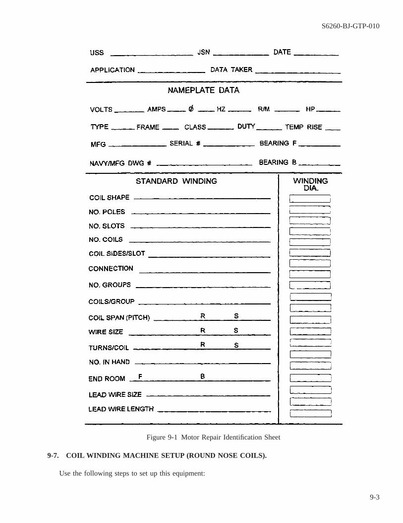
9-7. COIL WINDING MACHINE SETUP (ROUND NOSE COILS).
Use the following steps to set up this equipment:
Figure 9-1 Motor Repair Identification Sheet
S6260-BJ-GTP-010
9-3
a. Mount the holder on the winding machine.
NOTE
It will be difficult to lay in the coil sides if the heads are too small. End roomwill be excessive if the heads are too large.
b. To select the heads for the coil, compare the coil span with the head size.
c. Place the holder in the horizontal position.
d. Mount the heads on the holder.
e. Set in the coil side length. The coil side length is the length of the stator slots plus 3/4 inch to allow for theslot cell cuff.
9-8. WINDING SAMPLE COILS AND WINDING GROUPS.
9-9. WINDING SAMPLE COILS.
Use the following procedure to wind sample coils:
a. Open the winding head and lock it open. Tighten the T handle to lock the end strips.
b. Adjust the winding machine to a safe operating speed. Check the machine manufacturers instruction book forspeed adjustment.
c. Test the winding machine brake. The head should stop quickly and positively when the foot control isreleased. Refer to the machine manufacturer’s instruction book for instructions on brake adjustment.
d. Select the proper size and number of reels of magnet wire. Discard broken or cracked reels.
(1) Use the size wire recorded on the motor repair identification sheet (figure 9-1).
(2) There must be one reel, or bucket, of wire for each wire in hand. See the motor repair identification sheet.
NOTE
Dereeling from reels mounted on horizontal bars will result in wire spillage andwaste, even at moderate speeds.
e. Mount the reels on low-inertia dereelers.
f. Use a tensioning device to lead the wire from the dereelers over the winding machine wire guide bar (figure9-2) to the winding head.
S6260-BJ-GTP-010
9-4

(1) The tensioning device prevents wire crossover if properly adjusted.
(2) The wire guide bar slots should line up with the slots in the winding heads. This makes it easier to feedwire to the head and to keep it in the right slot.
(3) The bar is also a safety device that prevents the winder from being pulled against the rotating heads.
g. Hook the wire securely to the winding head.
h. Set the machine counter to zero. Set the number of turns in one coil into the control if the machine is auto-matic.
i. Wind a sample coil with the proper number of turns.
j. Tie the coil in the center of both coil sides (figure 9-3).
k. Cut the magnet wire at the guide bar. Loop the end which goes to the reels over the bars. Do not allow themagnet wire to fall on the deck. This will prevent damage to the wire insulating film.
Figure 9-2 Winding Head and Wire Guides
S6260-BJ-GTP-010
9-5
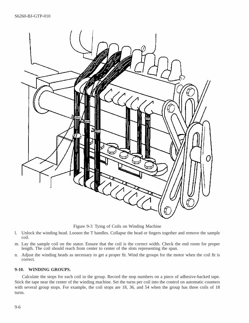
l. Unlock the winding head. Loosen the T handles. Collapse the head or fingers together and remove the samplecoil.
m. Lay the sample coil on the stator. Ensure that the coil is the correct width. Check the end room for properlength. The coil should reach from center to center of the slots representing the span.
n. Adjust the winding heads as necessary to get a proper fit. Wind the groups for the motor when the coil fit iscorrect.
9-10. WINDING GROUPS.
Calculate the stops for each coil in the group. Record the stop numbers on a piece of adhesive-backed tape.Stick the tape near the center of the winding machine. Set the turns per coil into the control on automatic counterswith several group stops. For example, the coil stops are 18, 36, and 54 when the group has three coils of 18turns.
Figure 9-3 Tying of Coils on Winding Machine
S6260-BJ-GTP-010
9-6
9-11. WINDING THE FIRST COIL.
Use the following procedure for winding the first coil:
a. Position the winding head to the desired start position.
b. Open the head and lock it in the open position.
c. Secure the end of the magnet wire to the head.
d. Set the machine counter to zero. Reset the control on automatic machines and set the manual counter to zero.
e. Wind the proper number of turns for one coil. Be sure that the winding head stops in the same position inwhich it started. Cross the magnet wire over to the next slot in the head. The wire should enter this slot in thesame way that the start wire of the first coil entered the first slot.
NOTE
The magnet wire must pass through the fingers. Stop the machine and discard thegroup if nicks or breaks in the insulating film can be felt.
9-12. WINDING SUBSEQUENT COILS.
Wind the second coil in the same manner as the first. Always stop the winding head in the same place.Always cross over to the slot in the same place. Continue until the group is finished. Check for nicks or breaksin the insulating film.
9-13. POSTWINDING PROCEDURE.
Use the following procedure after the last coil in the group is wound:
a. Turn off the winding machine.
b. Tie the last coil wound in the middle of the back coil side. Use cotton twine.
c. Cut the magnet wire at the wire guide bar.
d. Pull the cut end of the wire to the group straight out from the back coil side.
e. Loop the end of the wire going to the reels over the guide bar. This will prevent it from falling to the floor.
f. Tie all of the remaining coil sides in the middle. Use cotton twine.
g. Release the starting end of the group from the winding head.
h. Loosen the T handle. Collapse the winding head and remove the group.
i. Lay the group on a clean flat surface or hang it on a coil rack.
NOTE
Do not tape the coil crossovers or group leads to the coils (figure 9-4).
9-14. TAPING COILS.
Use the following procedure to tape coils:
S6260-BJ-GTP-010
9-7

a. Pull the group leads straight from their respective coil sides.
b. Wrap the center of the end turns of each coil with one and one-half turns of adhesive-backed glass tape, 3/4inch to 1/2 inch wide.
c. Stow the taped coils where they cannot be damaged.
9-15. INSULATION PREPARATION.
9-16.
Four types of insulation are used in winding. They are:
9-16.1 Slot insulation,
9-16.2 Coil side separators,
9-16.3 Slot wedges, and
9-16.4 Phase insulation.
Figure 9-4 Tape Applied to Coils
S6260-BJ-GTP-010
9-8

NOTE
See Appendix F for a list of materials to be used in the preparation of motorinsulation.
Commercially available precuffed slot cell insulation reduces the number ofman-hours that are required to form the cuffs by hand.
9-17. SLOT INSULATION.
Slot or ground insulation separates the coil sides in the slot from the laminations. It is prepared from two7-mil (0.007 inch)-thick pieces of polyamide (NOMEX) insulating material. To prepare the insulation:
a. Form enough NOMEX to make one insulator for each slot. Cut strips long enough to be 1-1/2 inches widerthan twice the depth of the stator slot. To obtain that measurement, push a sample of the NOMEX into a slot.Mark 3/4-inch extensions above the slot, then measure the distance between the marks. The length of NOMEXneeded will be the number of slots multiplied by the measured distance, multiplied by a factor of 1.1.
NOTE
The tear strength of NOMEX insulation is greater in one direction than the other.Cut the slot insulation so the higher tear strength is parallel to the slot. The redline on the NOMEX insulation will be circumferential to the stator bore.
b. Use the insulation forming machine to form a 3/8-inch cuff on each edge of the strip of NOMEX (figure 9-5).
S6260-BJ-GTP-010
9-9
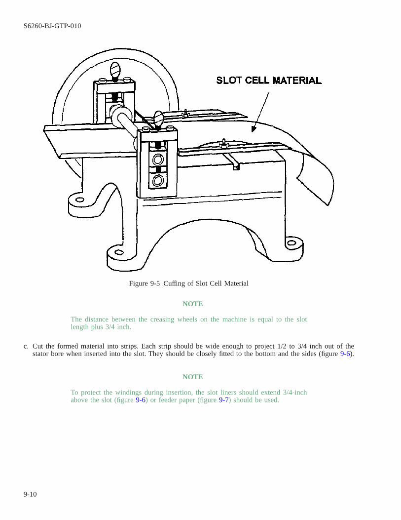
NOTE
The distance between the creasing wheels on the machine is equal to the slotlength plus 3/4 inch.
c. Cut the formed material into strips. Each strip should be wide enough to project 1/2 to 3/4 inch out of thestator bore when inserted into the slot. They should be closely fitted to the bottom and the sides (figure 9-6).
NOTE
To protect the windings during insertion, the slot liners should extend 3/4-inchabove the slot (figure 9-6) or feeder paper (figure 9-7) should be used.
Figure 9-5 Cuffing of Slot Cell Material
S6260-BJ-GTP-010
9-10

d. Cut the second piece of slot insulation in the same manner as the first. This piece of insulation should be 3/4inch narrower than the width of the cuffed pieces (figure 9-8).
e. Fold the cuffs over the formed pieces of NOMEX (figure 9-9).
f. Insert the uncuffed piece of insulation between the cuffs (figure 9-10).
Figure 9-6 Method of Fitting Slot Insulation
Figure 9-7 Slot Cell Width Precut with Feeder Paper
S6260-BJ-GTP-010
9-11

g. Prepare one slot insulator for each slot. Put them aside.
9-18. COIL SEPARATORS.
Coil separators are placed on top of coil sides as they are laid in the slots. This prevents the two coil sidesin the same slot from touching. To lock in the phase paper, separators are cut 1/2 inch longer than the slot insu-lation. Separators may be flat silicon glass or formed NOMEX. The separator length is the length of the slot plus1-1/2 inches. Prepare a coil side separator for each slot in a winding.
Figure 9-8 Lengths of Slot Insulator Pieces
Figure 9-9 Folding Slot Insulation Cuffs
S6260-BJ-GTP-010
9-12

CAUTION
Do not use silicone glass laminate or varnished glass-fiber cloth in a totallyenclosed motor-generator set if one machine is direct current with carbonbrushes. This arrangement causes excessive carbon brush wear.
9-19. WEDGES.
Wedges are used to close the slots. They should be cut from a silicon glass sheet when the insulation is pre-pared as shown in figure 9-11. Formed NOMEX may also be used as wedges.
9-20. PHASE INSULATION.
Phase insulation (phase papers) prevents the ends of coils in different pole phase groups from touching. Phaseinsulation is prepared from NOMEX or varnished glass fiber cloth with a thickness not less than 0.007 inch.Phase insulation must butt against the ground insulation. It must be wide enough to completely separate the coilsof adjacent groups. The phase insulation is prepared as a triangle. It is trimmed after it is in place. It is lockedin place by coil side separators.
9-21. WINDING THE STATOR.
9-22.
Inspect the stator for lumps of varnish, sharp edges on the laminations, sprung laminations, and cleanliness.Correct any condition which may affect the winding before laying in the coils.
Figure 9-10 Fitting the Pieces of a Slot Insulator
Figure 9-11 Slot Insulation Fitting for Feeder Paper
S6260-BJ-GTP-010
9-13
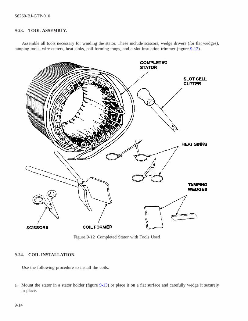
9-23. TOOL ASSEMBLY.
Assemble all tools necessary for winding the stator. These include scissors, wedge drivers (for flat wedges),tamping tools, wire cutters, heat sinks, coil forming tongs, and a slot insulation trimmer (figure 9-12).
9-24. COIL INSTALLATION.
Use the following procedure to install the coils:
a. Mount the stator in a stator holder (figure 9-13) or place it on a flat surface and carefully wedge it securelyin place.
Figure 9-12 Completed Stator with Tools Used
S6260-BJ-GTP-010
9-14
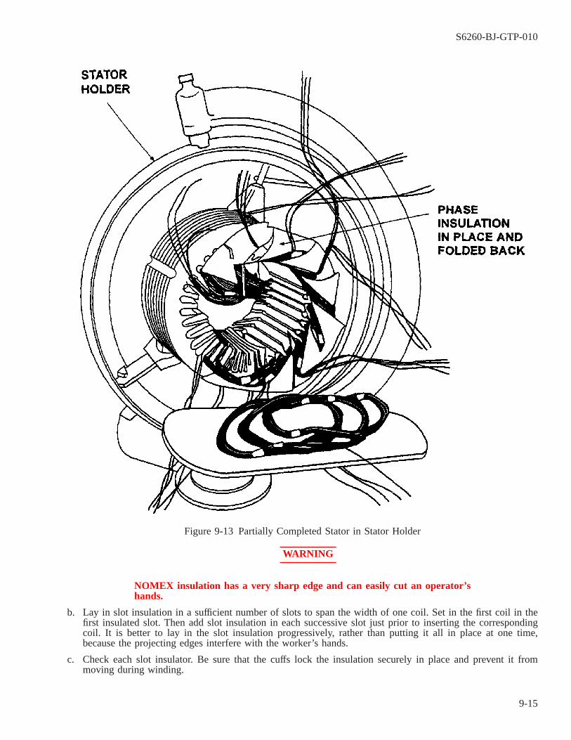
WARNING
NOMEX insulation has a very sharp edge and can easily cut an operator’shands.
b. Lay in slot insulation in a sufficient number of slots to span the width of one coil. Set in the first coil in thefirst insulated slot. Then add slot insulation in each successive slot just prior to inserting the correspondingcoil. It is better to lay in the slot insulation progressively, rather than putting it all in place at one time,because the projecting edges interfere with the worker’s hands.
c. Check each slot insulator. Be sure that the cuffs lock the insulation securely in place and prevent it frommoving during winding.
Figure 9-13 Partially Completed Stator in Stator Holder
S6260-BJ-GTP-010
9-15

d. The slot insulation should project 1/2 to 3/4 inch into the bore if prepared as shown in figure 9-6.
e. Slot insulation, prepared as shown in figure 9-11, will require feeder paper the same length as the slot insu-lation. It should also be wide enough to reach from the bottom of the slot and project 3/4 inch into the bore.The feeder paper will protect the magnet wire from chafing against the laminations as it is fed into the slot(figure 9-7).
f. A piece of NOMEX should be cut about 2 inches wider than the length of the stator core. It should be longenough to fit halfway around the inner periphery of the stator core. It should be used to ensure that the sta-tor iron will not damage the magnet wire insulation of the first few coils installed.
g. Lay one group adjacent to the connection side of the stator with the group leads and the crossovers pointingtoward the stator.
h. Pick up the top coil of the group by the end which is away from the stator. Remove the tie cord on the firstside to be laid into the slot.
i. Reach through the stator with one hand from the side opposite the connection side. Take the end of the coilfurthest from the stator with that hand. Hold the end closest to the stator with the other hand. Pull the coilthrough the bore. The group lead and crossover should still be on the connection side of the stator.
j. Spread the conductors at the bottom of one straight section of the coil with gentle manual pressure. Feed theconductors between the extensions of the ground insulation which protrude into the stator bore. Slide the coilinto the slot (figure 9-14).
k. Ensure that the conductors are resting in an orderly manner in the slot. Ensure that the conductors are notcrossing or crowding. When one side of the first coil span is in its proper slot, the other sides of these coilswill be loose in the stator bore. They will be on top of the piece of ground insulation mentioned in the para-graph above (figure 9-15).
Figure 9-14 Placing of Coil Sides from Slot Edges
S6260-BJ-GTP-010
9-16

l. Insert a coil separator on top of the coil section in the slot. The ends of the separators should extend 1/4 inchout of each end. Continue laying in one coil side of each coil until a coil span is laid in.
m. The next coil can then be completely laid in. One half of the coil goes in the bottom half of the next emptyslot. The other half goes in the top half of the slot with the coil separator. Ensure that the coil separator com-pletely separates the conductors of one coil from those of the other coils in the slot.
n. Check the insulation of the filled slot.
9-25. PREPARATION OF SLOT FOR CLOSING.
Use the following procedure to prepare the slot for closing:
a. From each end of the winding, place two temporary wedges in the slot. The wedges should meet in the middleof the slot. This protects the coil from the insulation trimmer. The temporary wedges also hold the insulationagainst the sides of the slot (figure 9-16).
Figure 9-15 Protection of Coil Sides from Slot Edges
S6260-BJ-GTP-010
9-17
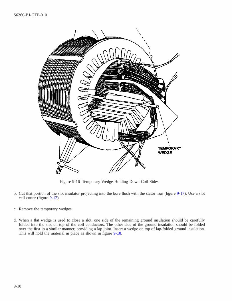
b. Cut that portion of the slot insulator projecting into the bore flush with the stator iron (figure 9-17). Use a slotcell cutter (figure 9-12).
c. Remove the temporary wedges.
d. When a flat wedge is used to close a slot, one side of the remaining ground insulation should be carefullyfolded into the slot on top of the coil conductors. The other side of the ground insulation should be foldedover the first in a similar manner, providing a lap joint. Insert a wedge on top of lap-folded ground insulation.This will hold the material in place as shown in figure 9-18.
Figure 9-16 Temporary Wedge Holding Down Coil Sides
S6260-BJ-GTP-010
9-18

e. To ensure that leads to the same group can be identified, loosely twist the group ends together after all thecoils of a group are laid in the slots. Keep the leads pulled back out of the bore.
NOTE
To lay in the last coils, it is necessary to remove the piece of NOMEX used toprotect the first span.
f. Continue this procedure until all slots have one coil in the bottom of the slot. The top coils of the first spanwill not be in the tops of their slots. These coil sides may now be laid in their slots. The slots may be closedas described in step a through d above.
CAUTION
Do not allow the scissors to cut or abrade the magnet wire insulation.
g. Phase insulation should now be placed between the groups of coils, as shown in figure 9-19, if insulation was
Figure 9-17 Cutting of Slot Cell Material
S6260-BJ-GTP-010
9-19
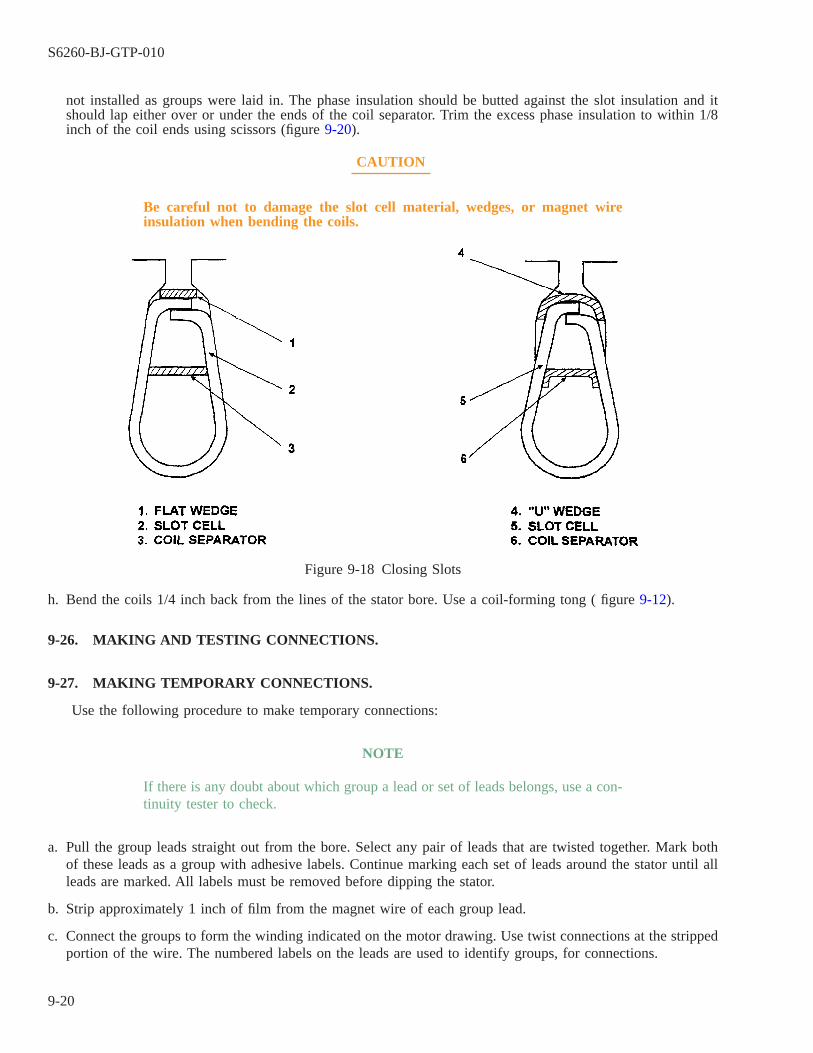
not installed as groups were laid in. The phase insulation should be butted against the slot insulation and itshould lap either over or under the ends of the coil separator. Trim the excess phase insulation to within 1/8inch of the coil ends using scissors (figure 9-20).
CAUTION
Be careful not to damage the slot cell material, wedges, or magnet wireinsulation when bending the coils.
h. Bend the coils 1/4 inch back from the lines of the stator bore. Use a coil-forming tong ( figure 9-12).
9-26. MAKING AND TESTING CONNECTIONS.
9-27. MAKING TEMPORARY CONNECTIONS.
Use the following procedure to make temporary connections:
NOTE
If there is any doubt about which group a lead or set of leads belongs, use a con-tinuity tester to check.
a. Pull the group leads straight out from the bore. Select any pair of leads that are twisted together. Mark bothof these leads as a group with adhesive labels. Continue marking each set of leads around the stator until allleads are marked. All labels must be removed before dipping the stator.
b. Strip approximately 1 inch of film from the magnet wire of each group lead.
c. Connect the groups to form the winding indicated on the motor drawing. Use twist connections at the strippedportion of the wire. The numbered labels on the leads are used to identify groups, for connections.
Figure 9-18 Closing Slots
S6260-BJ-GTP-010
9-20

NOTE
This is a temporary connection used for testing the winding.
9-28. TESTING THE TEMPORARY WINDING CONNECTION.
Use the following procedure to test the temporary windings:
a. Test the winding for grounds, using a General Radio 1644A or 1863, or equivalent megohmmeter (paragraph2-4 and paragraph 2-8).
b. Perform a phase balance test on the winding. Use a low-reading digital ohmmeter (Valhalla or equivalent).Refer to paragraph 2-15 for information on how to use the instrument.
c. Perform a surge comparison test on the winding. Use a Baker ST112E surge comparison tester (paragraph2-19).
Figure 9-19 Placement of Phase Material
S6260-BJ-GTP-010
9-21

d. Perform a dc high-potential test. Use a Baker ST112E surge comparison tester/high-potential tester (paragraph2-23).
e. Correct any problems indicated by these tests before making the permanent connections.
9-29. PERMANENT GROUP CONNECTIONS.
Use the following procedure to make permanent connections:
a. Cut one of the temporary connections.
b. Dress the group leads in this connection around the end of the winding. Determine the point at which the con-nection will be made on the winding. Carefully dress the group and line leads around the winding end. Allconnections must be long enough to be laced to end turns of the winding without excess length.
c. Mark the group lead at the point of connection. Cut the lead at least 1 inch beyond this point to allow formaking the connection.
d. Remove all tape or markers from the magnet wire.
Figure 9-20 Trimming of Phase Material
S6260-BJ-GTP-010
9-22
e. Select a small sleeving which will fit snugly over the group lead. Cut two pieces of sleeving long enough toprevent the lead from touching any coils it will cross going to the connection.
f. Select a sleeving large enough to slip over the small sleeving and the soldered connection. Cut a piece of thissleeving long enough to project approximately 1 inch on either side of the connection.
g. Slip the piece of large sleeving over the small sleeving.
h. Strip approximately 1 inch of insulating film from the magnet wire of the group leads.
i. Twist the group leads tightly together. Pliers may be used to twist the leads to ensure a tight connection. AWestern Union splice is preferred.
j. Cut the remaining temporary connections one at a time. Make up the remaining connections in the mannerdescribed above.
9-30. SOLDERING CONNECTIONS.
Use the following procedure to solder connections:
a. Pull the connections away from the winding so that solder will not fall into the winding. Slide a small pieceof insulation paper between the winding and the connection to be soldered.
b. Attach heat sinks to either end of the connection to be soldered. This will protect the magnet wire film fromthe heat of the iron (figure 9-21).
c. Apply the soldering iron to the bottom side of the connection. Allow the heat to rise from the iron through thewire.
d. Touch the solder to the top of the connection. Allow the solder to touch only the wire and then flow downthrough the connection. Use only SN-10 solder, QQ-S-571, with rosin flux.
e. Solder all connections. Lay the soldered connections tightly against the group leads.
f. Slide the large sleeving over the soldered connection and small sleeving. Center the large sleeve over the con-nection.
NOTE
The lead lines can be given added strength by going the long way around thecrown of the winding to the connection box with the line leads.
9-31. CONNECTING LEAD WIRES.
Cut lengths of lead wire long enough to reach the connection of the connection box. The wire should go thelong way from the group lead connection to the connection box (figure 9-21 and figure 9-22). Allow for at least10 inches of lead wire in the connection box.
a. Make the connections to the group lead wires in the same manner as group connections.
b. Solder the connections and cover with lengths of large sleeving material (figure 9-23).
S6260-BJ-GTP-010
9-23

9-32. LACING WINDING END TURNS.
Carefully inspect the windings and insulation before lacing the winding end turns. Ensure that the coil sideseparators and slot wedges are in place and extending uniformly from each slot. The phase insulation should bein place and lapping the ends of the coil side separators. Inspect for foreign particles or small scraps of materialcaught in the windings. Use Appendix C as a guide for inspecting the windings.
a. Cut 6 to 8 feet of approved lacing material. See Appendix F.
NOTE
Lacing may start at any point when lacing the end with no connections.
b. Insert the end of the lacing through the space between the coils next to the stator iron. Pull up and repeat fortwo turns. Pull tightly and tie with a square knot, leaving enough bitter end on the short side to secure thefinishing end of the lacing (figure 9-22).
c. Insert the end of the lacing through the space next to the stator iron for the next two coils. Pull the excesslacing through. Hold the standing part of the lacing. Twist an eye and pass the loose end of the lacing throughthe eye. Pull it up tight to form a rolling hitch. This will keep slack out of the completed lacing. Continuelacing along the crown of the windings. Proceed as follows if the round turn is to be used to lace: Start lac-
Figure 9-21 Heat Sinks in Place and Placement of Sleeving
S6260-BJ-GTP-010
9-24
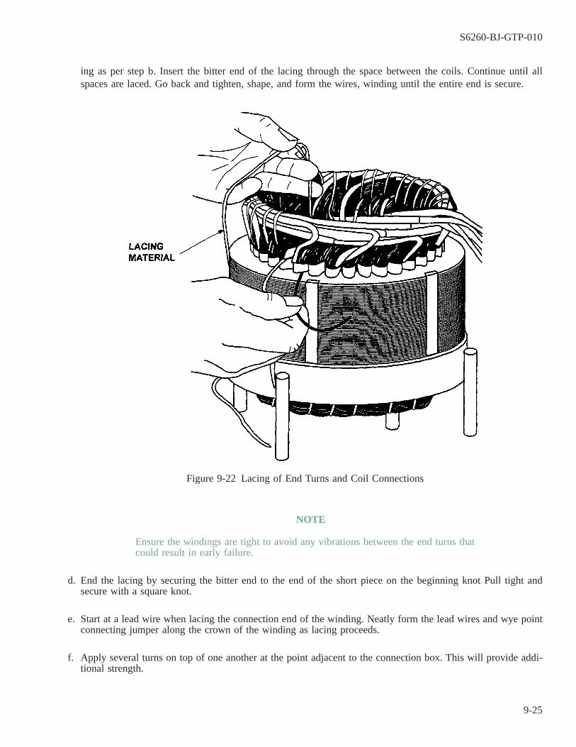
ing as per step b. Insert the bitter end of the lacing through the space between the coils. Continue until allspaces are laced. Go back and tighten, shape, and form the wires, winding until the entire end is secure.
NOTE
Ensure the windings are tight to avoid any vibrations between the end turns thatcould result in early failure.
d. End the lacing by securing the bitter end to the end of the short piece on the beginning knot Pull tight andsecure with a square knot.
e. Start at a lead wire when lacing the connection end of the winding. Neatly form the lead wires and wye pointconnecting jumper along the crown of the winding as lacing proceeds.
f. Apply several turns on top of one another at the point adjacent to the connection box. This will provide addi-tional strength.
Figure 9-22 Lacing of End Turns and Coil Connections
S6260-BJ-GTP-010
9-25
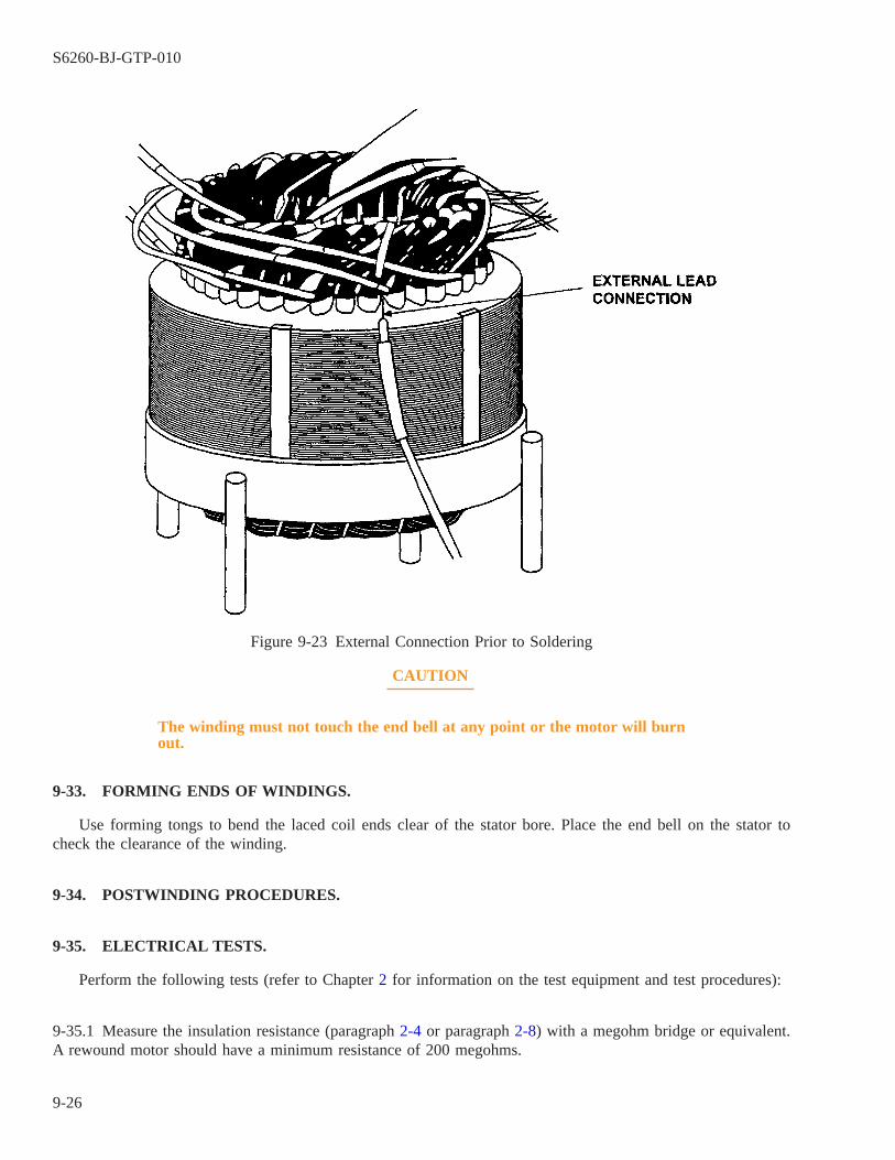
CAUTION
The winding must not touch the end bell at any point or the motor will burnout.
9-33. FORMING ENDS OF WINDINGS.
Use forming tongs to bend the laced coil ends clear of the stator bore. Place the end bell on the stator tocheck the clearance of the winding.
9-34. POSTWINDING PROCEDURES.
9-35. ELECTRICAL TESTS.
Perform the following tests (refer to Chapter 2 for information on the test equipment and test procedures):
9-35.1 Measure the insulation resistance (paragraph 2-4 or paragraph 2-8) with a megohm bridge or equivalent.A rewound motor should have a minimum resistance of 200 megohms.
Figure 9-23 External Connection Prior to Soldering
S6260-BJ-GTP-010
9-26
9-35.2 Measure the winding phase resistance with a digital ohmmeter (paragraph 2-15). Winding phase resistancereadings should be within 5 percent of each other.
9-35.3 Perform a surge comparison test (paragraph 2-19) on the windings. Use a Baker surge comparison testeror equivalent. There should be no disparity of patterns displayed and the full calculated voltage should be applied.
9-35.4 Perform a dc high-potential test (paragraph 2-23) on the windings. Plot the voltage and current on graphpaper and the shape of the resultant curve is used for checking the cleanliness of the winding, the moisture con-tent of the winding tested, and the dielectric strength of the winding.
9-36. VISUAL INSPECTION.
Make a visual inspection using the checklist in Appendix C. Correct any deficiencies.
9-37. ANNEALING.
The stator should now be put in an oven at 302° F (150° C) for 4 hours. This will anneal the magnet wireand ensure that all moisture is removed from the insulating materials before varnishing.
9-38. REWINDING MOTORS WITH A SEALED INSULATION SYSTEM (SIS).
9-38.1 Motors with a sealed insulation system that require rewind should be rewound with a sealed insulationsystem by a facility certified by NAVSEA. If motor rewind using a sealed insulation system will result in signifi-cant impact on the ship’s schedule, the motor may be rewound with a Class F nonsealed insulation system, pro-vided formal concurrence is obtained from the cognizant planning yard or design agent. However, the informa-tion plate identifying the motor as having sealed insulation must remain on the motor.
9-38.2 Since sealed insulation provides greater reliability, the motor should eventually be rewound with sealedinsulation at the discretion of the Type Commander. Fire pump and air conditioning plant compressor motorsoriginally provided with sealed insulation that have been rewound with nonsealed insulation should be rewoundat the earliest opportunity with a sealed insulation system. Motors originally provided with sealed insulation thatfail after rewind with nonsealed insulation should be rewound at the earliest opportunity with a sealed insulationsystem. The insulation system originally provided in the motor can be determined by review of the motor draw-ing in the auxiliary equipment technical manual. Another means of identification is the information plate locatedon sealed insulated motors that indicates that the motor was previously wound with sealed insulation.
9-38.3 Sealed insulation isolates motor windings from high humidity, salt-laden atmospheres, and/or water expo-sure. Certified repair facilities take great care to ensure that the motor winding’s sealed insulation is free of cracksor other damage; Each sealed insulated stator must pass a 24-hour submergence test prior to delivery to the ship.Care must be taken when handling these motors to prevent damaging the insulation and negating the advantagesof this higher cost insulation system.
9-38.3.1 Do not pull on the motor leads when making electrical connections. Prior to rigging, ensure the motorleads are inside the terminal box.
9-38.3.2 When rigging a sealed insulation motor, handle with care. Use eyebolts and lifting eyes where avail-able. Do not allow the motor to be dropped or exposed to other high impacts during rigging and installation.
S6260-BJ-GTP-010
9-27 / (9-28 Blank)

9-28@@FIpgtype@@BLANK@@!FIpgtype@@

CHAPTER 10
VARNISHING
10-1. SCOPE.
This chapter includes information on the use of varnish and procedures for varnishing new and reconditionedwindings by dipping. Topics include:
10-1.1 Characteristics of varnish (paragraph 10-2).
10-1.2 Terminology used with varnish (paragraph 10-3).
10-1.3 Varnish selection criteria (paragraph 10-4).
10-1.4 Functional considerations of varnish (paragraph 10-5).
10-1.5 Construction of a varnish tank (paragraph 10-8).
10-1.6 Varnish testing (paragraph 10-19).
10-1.7 Thinning and storing varnish (paragraph 10-20).
10-1.8 Varnishing reconditioned windings (paragraph 10-23).
10-1.9 Varnishing new windings (paragraph 10-27).
10-2. CHARACTERISTICS OF VARNISH.
10-2.1 Solvent-Containing Varnish. All varnishes of this type that are received from stock for general useshould be Class 155. Stock numbers for Class 155 varnish and its thinners are listed in Appendix F. Red-pigmented, alkyd-resin varnishes must not be used on bindings or coils for electrical equipment.
10-2.2 Solventless Varnish. Solventless dip varnish must be used when environmental regulations prohibit theuse of solvent-containing varnishes. NAVSEA is the point of contact for information on acceptable solventlessvarnishes.
NOTE
Solventless varnishes Isolite 862M and Esterlite 605 are approved for use by allIMAs. Follow the manufacturer’s instructions for use.
10-2.2.1 Shipboard repair activities are required to use solventless dip varnishes. Their high flash point, greaterthan 200° F (93° C) eliminates the fire hazard posed by solvent-containing varnishes. Solventless varnish shouldalso be used by repair activities required to meet environmental regulations limiting the emission of volatileorganic compounds (VOCs) into the atmosphere. Some solventless varnishes are not suitable for use with sub-marine equipment because the cured varnish emits excessive levels of undesirable chemical compounds into theatmosphere. Testing done under the auspices of the Submarine Materials Control Program has identified solvent-less varnishes that are suitable for use with submarine equipment. Consult NAVSEA S9086-KC-STM-010/CH300 for the submarine-approved solventless dip varnishes. Equipment for use on surface ships may be varnishedusing any solventless varnish determined by the cognizant Naval Supervising Activity to be acceptable in accor-dance with NAVSEA S9086-KC-STM-010/CH 300.
S6260-BJ-GTP-010
10-1
10-2.2.2 This type of varnish typically has a greater bond strength than solvent-containing varnish; however,varnish build is often less than half of that of the solvent-containing types. Most solventless varnishes will notovercoat windings that have been previously treated with any of a wide variety of solvent-containing varnishesused by naval and commercial activities. When using solventless dip varnishes, the dipping procedure of para-graph 10-31 maybe modified by the varnish manufacturers procedure. Although solventless varnishes have notshown that multicoating is successful, three dips and bakes are recommended to ensure adequate single coat cov-erage. Solventless dip varnishes should not be used to overcoat windings that have been previously treated withsilicone varnish. Because of their chemistry, these windings offer a poor surface for revarnishing.
CAUTION
Compatibility tests must be conducted between varnish held in the dip tankfor over a month and varnish from closed containers. Do this even thoughmanufacturer and batch numbers are the same.
10-3. TERMINOLOGY USED WITH VARNISH.
10-3.1 Solvent-Containing Varnishes. These are liquid solutions of solid, polymeric materials dissolved in asuitable solvent primarily for application by the dip and bake process. The initial solid, polymeric material isgenerally an alkyd or modified alkyd and the solvent most often is xylene. Some suppliers refer to the alkyd asa polyester and the modified alkyd as a modified polyester . They may also use the term phenolic modified poly-ester . These materials are actually complex mixtures of compounds of intermediate molecular weight producedby a chemical process called polyesterification . The solids content generally runs close to 50 percent by weight.
10-3.2 Solventless Polyesters. These resins consist of a solid resin dissolved in a liquid monomer such as vinyltoluene, or DAP (diallyl phthalate). They are referred to as reactive or unsaturated, polyesters . They do not con-tain solvent. Instead, the monomers react with the basic resin and become part of the final, cured coating. Sol-ventless resins or varnishes are sometimes referred to as 100-percent solid materials . Since there are no solventsto evaporate, there is less likelihood of blistering, bubbles, and cavities.
10-3.3 Solventless Epoxies. Like the solventless polyesters, these materials contain no solvents. The basematerial is a high-viscosity liquid epoxy. A selective amount of a diluent, which is a low-viscosity epoxy, is addedto yield the final desired viscosity range. The solventless epoxies have certain properties that distinguish themfrom the solventless polyesters.
10-3.4 Other Liquid Polymeric Materials. This category includes materials that, for one reason or another, arenot as popular as the materials covered above.
10-3.5 Polybutadienes. This class of polymeric material consists of an aliphatic hydrocarbon resin dissolved ina solvent or monomer mixture, usually consisting of naphtha, xylene, and/or vinyl toluene.
10-3.6 Silicones. These are resinous materials made from compounds, which in place of the usual carbonbackbone, have a backbone of silicon and oxygen atoms. Such a structure offers excellent resistance to oxidationat elevated temperatures. Silicone resins are not to be used on enclosed rotary Navy equipment that operates withcarbon brushes since certain silicone vapors can cause severe commutation problems such as excessive brushwear. Solvent solutions of these silicone polymers have been used as varnishes for many years and are recog-
S6260-BJ-GTP-010
10-2

nized for their outstanding long-term thermal resistance. However, in recent years they have been replaced withspecially modified polyesters which have slightly less thermal stability but offer higher bond strengths at elevatedtemperatures.
10-3.7 Patching Kits. These consist of polymeric materials for temporary insulation where damage to the insu-lation has occurred. Patching kits can be a single component polyurethane varnish, supplied in a can for brushapplication or in a pressurized container for spray applications. These kits can also consist of a two-componentepoxy system designed for relatively quick solidification. Since this system is solventless, it may offer an advan-tage when toxicity and low flash point are critical.
10-3.8 Thixotropic Varnishes. These are a class of varnish materials in which the flow characteristics have beenmodified so that the normal build, or coating thickness, is greatly increased. Thixotropy , by definition, is theability of certain colloidal gels to liquefy when agitated (as by shaking or ultrasonic vibration) and to return tothe gel form when at rest. Most electrical varnishes yield a build between 0.5 and 1.2 mils after one dip or treat-ment. The thixotropic materials will yield 2 to 10 mils, depending on the degree of modification. This specialmodification is accomplished through the addition of a thixotropic agent which is normally a finely ground min-eral filler. This addition is made by the manufacturer but, in some cases, slight additions have been made at thevarnish treating facilities to reestablish the original degree of thixotropy. For Navy applications, thixotropicmodification has been used only with the solventless type of varnishes and only with the vacuum-pressureimpregnation (VPI) process. There is the possibility in the future that these materials may be used in the dip andbake process.
10-3.9 Cure. A varnish or resin must be thoroughly cured or polymerized to achieve its intended purpose. Anelectrical varnish is designed to provide: mechanical bonding, environmental protection, and a dielectric barrierbetween points of differing electrical potential. If the varnish has not been adequately polymerized, that is,chemically or thermally reacted from a liquid to a solid stare, it will not fully provide these functions.
10-4. VARNISH SELECTION CRITERIA.
10-4.1 Solvent-Containing Varnish. Solvent-containing varnish should be selected in accordance with MIL-I-24092.
10-4.2 Solventless Varnishes. They are not available as products qualified in accordance with military specifi-cations. Therefore, repair activities are responsible for the evaluation and selection of these commercially avail-able varnishes. The following guidance is provided to assist activities in this process.
10-4.2.1 As a minimum, the varnish manufacturer should be provided the following information at the begin-ning of the selection process:
1. Operating environments and types of equipment to be varnished.
2. Description of other insulating materials to be used.
3. Insulation class of equipment to be varnished.
4. Estimated average temperature of the varnish in the dip tank.
5. Estimated rate of varnish usage.
S6260-BJ-GTP-010
10-3
6. Local environmental and fire safety regulations.
10-4.3 Varnish characteristics such as bond strength, dielectric strength, varnish build, and others identified inMIL-I-24092 should be evaluated and compared to assist in choosing the most capable varnish.
10-4.4 Evaluation of solventless varnish must include a demonstration of compatibility between the varnish andthe principle components of the insulation system, including magnet wire, slot insulation, sleeving, and insulat-ing tapes. The varnish should provide a uniform coating, should penetrate materials as required, and should notreact adversely with the insulating materials. Materials should be checked for delamination and other physicalchanges after soaking in varnish. The repair activity should verify that the varnish has been qualified with therepair activity’s magnet wire and slot material per National Electrical Manufacturers’ Association (NEMA) stan-dard, REV 2.
10-5. FUNCTIONAL CONSIDERATIONS OF VARNISH.
10-5.1 Solventless Varnishes. These materials are used primarily when maximum bond strength is required.They yield a smooth, even coating. Since no solvent is being removed in the baking process, holes and blistersusually do not form.
10-5.2 Solventless Thixotropic Varnishes. Solventless varnishes are more effective when they are modified forthixotropy (paragraph 10-3.8). This results in a much heavier varnish build per application and effectivelyincreases the total encapsulation. This results in a strong, unified coil structure for motors, generators, and motorgenerator sets.
10-5.3 Gel Time of Solventless Varnishes. The gel time of a solventless resin is a measure of the reactivity ofthe resin, monomer, and catalyst system. If the gel time is too long, an optimum coating will not be achievedbecause some of the resin ingredients may evaporate in the curing oven before polymerization occurs. It may alsoresult in an inadequate coating thickness since the resin will stay in a liquid state for a longer period of time, andwill tend to run off of vertical and inclined surfaces.
10-5.3.1 Test Method. The gel time shall be measured on three catalyzed resin specimens in accordance withASTM D 3056, Gel Time for Solventless Varnishes, Test for . A bath temperature of 212, 257, or 302° F (100,125, or 150° C) shall be employed, and shall be chosen to give gel time between 10 and 60 minutes.
10-5.3.2 Test Instrument. The usual gel time instrument is a Sunshine Gel Time Meter and the test procedureis described in the instruction manual supplied by the instrument manufacturer.
10-5.3.3 Requirements. The gel time shall meet the requirements for periodic conformance as specified in theindividual specification sheets of MIL-I-24092.
10-5.3.4 Thixotropic Index. The thixotropic index measures the degree of resin retention on this equipment asit is being cured in this oven. A thixotropic solventless resin is used when heavy builds are required. The normalbuild for a solvent-containing varnish is on the order of 1 mil Using solventless resins that have been modifiedfor thixotropy, the build may reach 10 to 12 mils. As the tank resin is used, and as it ages, some undesirablechanges may occur. With thixotropic materials, resin retention is adversely effected and the thickness of the coat-
S6260-BJ-GTP-010
10-4

ing will be less than required. Thixotropy is best measured by comparing the resin viscosity measured at a lowspeed to the viscosity measured at a higher speed. The ratio of the low speed to the high speed viscosity yieldsthe thixotropic index.
10-5.3.4.1 Test Method and Procedure. The viscosity shall be measured at 73° F ± 2° F (23° C ± 1° C) cata-lyzed resin according to method B of ASTM D 2196, Rheological Properties of Non-Newtonian Materials, TestFor . The viscosity shall be determined at spindle speeds of 2 and 20 revolutions per minute (r/m). The resin orvarnish shall be placed in a 1-quart container within 1 inch of the top. Using a water bath, adjust the sample to73° F ± 2° F (23° C ± 1° C). After reaching the required temperature, wait 90 minutes before the first measure-ment is made at 2 r/m. The 20 r/m measurement shall then be made immediately after the 2 rpm measurements.Three tests at each speed shall be made to provide an average viscosity value. The thixotropic index shall be cal-culated as follows:
Thixotropic Index = Avg. vis. at 2 r/m / Avg. vis. at 20 r/m
10-5.3.4.2 Requirements. The thixotropic index must meet the requirements of the individual specificationsheets of MIL-I-24092. The test report shall include: model number of Brookfield viscometer, speed of rotation,spindle number, average viscosity at each speed, and calculated thixotropic index.
10-5.4 Solvent-Containing Varnishes. These varnishes are the general purpose liquid insulation materials usedfor insulating all types of electrical apparatus for over 35 years. As the solventless materials have become morewidely used, the solvent-containing varnishes are now limited to specialized applications such as the finish ortop-coat varnish. They are the preferred varnish for overcoating the solventless resin since they yield a veryglossy finish. After an electrical apparatus has been treated with this type of varnish, the solvent immediatelybegins to evaporate and, usually after less than 1 hour, depending on the temperature and local air movement, itdries to a tack-free coating. At this stage, the coating must be baked to achieve its final properties. Once this bakecycle is completed, the varnish coating has a high gloss and, although hard, is capable of absorbing the mechani-cal and thermal movements necessary for normal equipment performance.
10-6. VARNISH COMPATIBILITY.
All varnish received from stock should be from the same manufacturer or have the same batch number. It issometimes necessary, however, to mix varnish from different manufacturers or with different batch numbers. Inthis case, compatibility of the different varnishes must be proven by testing. Varnish compatibility is essentialbecause mixing two incompatible varnishes will produce clouding and precipitation. An incompatible mix willnot produce a good, adherent surface. Use the following procedure to test varnish compatibility:
a. Draw a small sample of varnish from each manufacturer or batch. Mix the samples together thoroughly.
CAUTION
Certain varnishes not qualified under MIL-I-24092 are likely to be incom-patible with varnish qualified under MIL-I-24092.
S6260-BJ-GTP-010
10-5
NOTE
Esterlite 862M solventless varnish has a high degree of compatibility with DAPand VT-based varnishes. However, a compatibility test is essential. Precipitationmeans that particles drop out and separate from the rest of the varnish.
b. Check the mix for precipitation, excessive thickening, or other signs of incompatibility.
c. Consult NAVSEA S9086-KC-STM-010/CH 300 for further information on varnish compatibility.
10-7. THINNER.
Thinners should also be tested for compatibility with varnish before use. Use the following procedure to testthinner compatibility:
a. Draw a small amount of varnish from the tank.
b. Add thinner to the varnish sample in the same ratio as the final ratio of thinner to varnish in the tank as deter-mined by paragraph 10-13. For example, if the tank has 10 gallons of varnish and 1 gallon of thinner will beadded, the sample compatibility test should be the same 10:1 ratio of varnish to thinner.
c. Thoroughly mix the varnish and thinner. Observe for signs of incompatibility, such as small gelatinous forma-tions or clouding. This can be more easily observed by dipping a spatula or glass slide into the varnish andthinner mixture. As the mixture flows from the spatula or glass slide, watch for clouding or other irregulari-ties.
10-8. CONSTRUCTION OF A VARNISH TANK.
WARNING
Do not permit smoking, welding, or open flames near an open tank. Varnishhas a very low flashpoint.
10-9.
The electrical shop supervisor should consult a motor frame chart to determine the dimensions of the requiredtank. A motor frame chart should be available in the shop.
10-10. TANK DIMENSIONS.
The tank should be:
10-10.1 Long and wide enough so that the largest frame expected can be easily lowered into the tank and
10-10.2 Deep enough to allow complete submergence of the stator.
S6260-BJ-GTP-010
10-6
10-11. TANK EQUIPMENT.
The tank should be equipped in the following manner:
10-11.1 The tank top should have hinges that allow it to swing completely clear of the tank.
10-11.2 The top should be fitted with a gasket that will form a vapor-tight seal when lowered against the tankedge. The top is held in place by dogs when closed. The dogs will pull the top gasket tightly against the tankedge to ensure a seal.
10-11.3 A drain pipe and valve must be mounted in the bottom of the tank to allow draining and cleaning.
NOTE
The following applies ONLY to varnish tanks for solvent-containing varnish.
10-11.4 The tank must have a filter system. The filter system will consist of a valve, a positive displacementpump, a filter, and a return line.
10-11.4.1 The suction line should be near the bottom of the tank, the valve between the tank and the pump, andthe filter on the pressure side of the pump. The return line for the varnish must discharge back into the tank,above the surface of the varnish.
10-11.4.2 Good circulation will be achieved by taking varnish by suction from the bottom of the tank andreturning it to the top. Discharging above the surface will provide thorough mixing of the varnish during treat-ment.
10-11.4.3 The pump’s capacity must be large enough to recirculate the tank twice an hour. Pump capacity is cal-culated by using the following formula:
Pump Capacity in Gallons per Minute (gal/min) = Tank Capacity in Gallons x 2/60
10-12. VARNISH TANK LOG.
A varnish tank log should be maintained for each varnish tank. The tank log should be kept in the follow-ing manner.
10-12.1 State what varnish was added to the tank, its manufacturer, and its batch number.
NOTE
The following applies ONLY to varnish tanks for solvent-containing varnish.
10-12.2 Run a weekly test (paragraph 10-13) on the varnish. The varnish tank log should state:
S6260-BJ-GTP-010
10-7
10-12.2.1 Date of the test,
10-12.2.2 Viscosity in centipoise,
10-12.2.3 Temperature of the varnish during the test,
10-12.2.4 Type of cup used,
10-12.2.5 Treatment necessary to correct the viscosity, and
10-12.2.6 Initials of the person conducting the test and making the correction.
NOTE
The following applies ONLY to varnish tanks for solvent-containing varnish.
10-13. VARNISH TESTING.
10-14. VISCOSITY OF SOLVENT-CONTAINING VARNISH.
Solvent-containing varnish qualified under MIL-I-24092 must be maintained at a viscosity as indicated in thevarnish manufacturer’s instruction sheets or product literature. Varnish is tested to determine its viscosity beforeuse. It need not be retested more than once a week. Use the following steps to test viscosity.
a. Ensure that the varnish temperature is 77° F ±3° F (25° C ± 2° C).
b. Ensure that the recirculation pump valve is open. Start the pump. Recirculate the varnish for 1 hour beforetesting viscosity.
c. Dip a viscosity measuring cup (Zahn No. 2 or Demmler No. 1) into the varnish and fill it.
d. Start the stopwatch as the cup emerges from the varnish. Liquid will begin to flow through the hole in thebottom of the cup.
e. Stop the watch at the first interruption of continuous flow of the varnish. Note the time.
10-15. RECORDING VISCOSITY WITH THE ZAHN CUP.
Use the following procedure to record viscosity:
a. Locate the time in seconds on the viscosity chart for the Zahn cup No. 2 (figure 10-1) on the line marked″Viscosity in seconds.″
b. Go up from this point to a point of intersection on the Zahn cup viscosity chart No. 2 line.
c. From this point, go left at right angles to the point of intersection with the Absolute Viscosity Line.
d. Read this point of intersection and record it in the varnish tank log as soon as the test is complete.
S6260-BJ-GTP-010
10-8

10-16. RECORDING VISCOSITY WITH THE DEMMLER CUP.
See figure 10-1 and use the following procedure to record viscosity:
a. Locate the time in seconds on the chart for No. 1 Demmler cup (figure 10-1) on the line marked ″VISCOS-ITY IN SECONDS.″
b. Go up from this point to a point of intersection of the Demmler cup No. 1 line.
c. From this intersection point, go left at a right angle to the point of intersection with the Absolute ViscosityLine.
d. Read this point of intersection and record it in the varnish tank log under ″VISCOSITY IN CENTIPOISE AT25° F (77° C).″
10-17. APPROXIMATE VISCOSITY MEASUREMENT.
An approximate viscosity measurement can be taken in the absence of a Zahn or Demmler cup. Use the fol-lowing procedure:
a. Use a small (about one-half pint) can with a small hole (not more than 1/8 inch in diameter) in the bottom.
b. Calibrate by filling the can with fresh water and observing the time it takes for the can to empty.
c. Dry the can and repeat with varnish.
NOTE
Water has a viscosity of 17 seconds by the Zahn cup No. 2 or the Demmler cupNo. 1. Therefore, viscosity of a liquid can be approximated by the formula:
17S/R = V, where
R reference value, the observed time in seconds for water,
S observed time in seconds for varnish, and.V seconds viscosity, Demmler or Zahn cup.
S6260-BJ-GTP-010
10-9
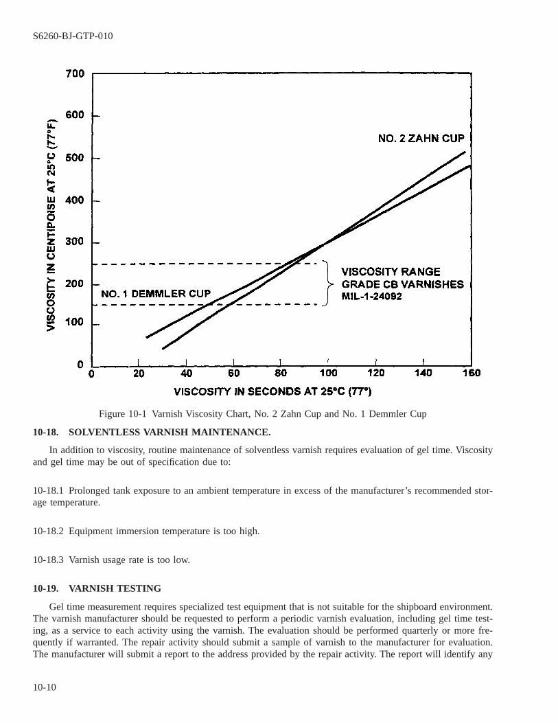
10-18. SOLVENTLESS VARNISH MAINTENANCE.
In addition to viscosity, routine maintenance of solventless varnish requires evaluation of gel time. Viscosityand gel time may be out of specification due to:
10-18.1 Prolonged tank exposure to an ambient temperature in excess of the manufacturer’s recommended stor-age temperature.
10-18.2 Equipment immersion temperature is too high.
10-18.3 Varnish usage rate is too low.
10-19. VARNISH TESTING
Gel time measurement requires specialized test equipment that is not suitable for the shipboard environment.The varnish manufacturer should be requested to perform a periodic varnish evaluation, including gel time test-ing, as a service to each activity using the varnish. The evaluation should be performed quarterly or more fre-quently if warranted. The repair activity should submit a sample of varnish to the manufacturer for evaluation.The manufacturer will submit a report to the address provided by the repair activity. The report will identify any
Figure 10-1 Varnish Viscosity Chart, No. 2 Zahn Cup and No. 1 Demmler Cup
S6260-BJ-GTP-010
10-10
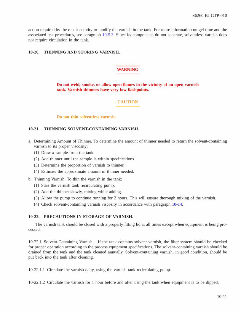
action required by the repair activity to modify the varnish in the tank. For more information on gel time and theassociated test procedures, see paragraph 10-5.3. Since its components do not separate, solventless varnish doesnot require circulation in the tank.
10-20. THINNING AND STORING VARNISH.
WARNING
Do not weld, smoke, or allow open flames in the vicinity of an open varnishtank. Varnish thinners have very low flashpoints.
CAUTION
Do not thin solventless varnish.
10-21. THINNING SOLVENT-CONTAINING VARNISH.
a. Determining Amount of Thinner. To determine the amount of thinner needed to return the solvent-containingvarnish to its proper viscosity:
(1) Draw a sample from the tank.
(2) Add thinner until the sample is within specifications.
(3) Determine the proportion of varnish to thinner.
(4) Estimate the approximate amount of thinner needed.
b. Thinning Varnish. To thin the varnish in the tank:
(1) Start the varnish tank recirculating pump.
(2) Add the thinner slowly, mixing while adding.
(3) Allow the pump to continue running for 2 hours. This will ensure thorough mixing of the varnish.
(4) Check solvent-containing varnish viscosity in accordance with paragraph 10-14.
10-22. PRECAUTIONS IN STORAGE OF VARNISH.
The varnish tank should be closed with a properly fitting lid at all times except when equipment is being pro-cessed.
10-22.1 Solvent-Containing Varnish. If the tank contains solvent varnish, the filter system should be checkedfor proper operation according to the process equipment specifications. The solvent-containing varnish should bedrained from the tank and the tank cleaned annually. Solvent-containing varnish, in good condition, should beput back into the tank after cleaning.
10-22.1.1 Circulate the varnish daily, using the varnish tank recirculating pump.
10-22.1.2 Circulate the varnish for 1 hour before and after using the tank when equipment is to be dipped.
S6260-BJ-GTP-010
10-11

10-22.1.3 Test the varnish once a week. Record the results in the varnish tank log.
10-22.1.4 Varnish should not be excessively thinned, as this will result in a baked film that will be too thin toafford electrical protection.
10-22.1.5 Varnish in the dip tank shall be maintained in accordance with NAVSEA S9086-KC-STM-010/CH300.
10-22.2 Solventless Varnish. If the tank contains solventless varnish, the recirculating pump and filter systemare not required. The varnish should be drained from the rank and the tank cleaned every 2 to 3 years.
10-23. VARNISHING RECONDITIONED WINDINGS
10-24.
Varnishing of reconditioned windings should:
10-24.1 Provide a continuous varnish film over the coils, core, and miscellaneous surfaces.
10-24.2 Provide a film which is comparatively resistant to gases, moisture, and oil.
10-24.3 Provide a smooth surface to minimize the collection of dust, dirt, and other substances on the surface ofthe windings.
CAUTION
Varnish should never be applied to the whole or any part of a winding,either by dipping, spraying, or brushing, until the winding has been thor-oughly cleaned and dried. Varnishing a dirty or moist winding seals in dirtor moisture and makes future cleaning impossible.
NOTE
Varnish should be applied only when it will serve a useful purpose. The unnec-essary and frequent application of varnish ultimately results in building up aheavy coating which interferes with heat dissipation and is likely to develop sur-face cracks.
10-25. PREPARING WINDINGS FOR VARNISHING.
Use the following procedure to prepare windings for varnishing:
a. Complete stator cleaning before varnishing.
b. Ensure that the winding is completely dry.
S6260-BJ-GTP-010
10-12

c. Ensure that the winding has an acceptable value of insulation resistance (see the After Reconditioning columnin table 7-2). Ensure that all other dielectric test results were satisfactory. Ensure that the winding and leadsdo not have physical damage.
d. Place bolts in bolt holes to prevent the entry of varnish. This is very important, since open bolt holes will fillsolidly with varnish.
e. Prepare rigging so that the position of the winding can be changed during draining. This will prevent pocket-ing of the varnish.
10-26. VARNISHING PROCEDURE.
When reconditioning, use table 10-1 for solvent-containing varnishes and table 10-2 for solventless varnishas described below for varnishing windings.
NOTE
One coating of varnish is usually sufficient when reconditioning windings. Thewinding undergoing reconditioning has several coats of varnish on it. The coatput on during reconditioning is intended to seal any minute cracks that havedeveloped due to vibration and thermal cycling. Sometimes, solventless varnishruns off a winding during reconditioning before the varnish sets up in the oven.If this occurs, and solvent-containing varnish is not available, rewind is neces-sary.
a. Complete steps 1 through 4 of the appropriate table.
b. Baking should be in accordance with in step 5 of the appropriate table.
c. Steps 7 through 8 are not required.
10-27. VARNISHING NEW WINDINGS.
Tables 10-1 and 10-2 list the procedures for using solvent-containing and solventless varnishes, respectively.
10-28.
Varnishing new windings should:
10-28.1 Seal the windings from dirt, oil and moisture.
10-28.2 Bind the winding into a solid mass.
10-28.3 Provide a film over the winding. The film must be as smooth as possible, with a glossy finish to mini-mize the collection of dirt and dust.
10-29. PREPARING A NEW WINDING FOR VARNISHING.
Use the following procedure to prepare a new winding for varnishing.
S6260-BJ-GTP-010
10-13
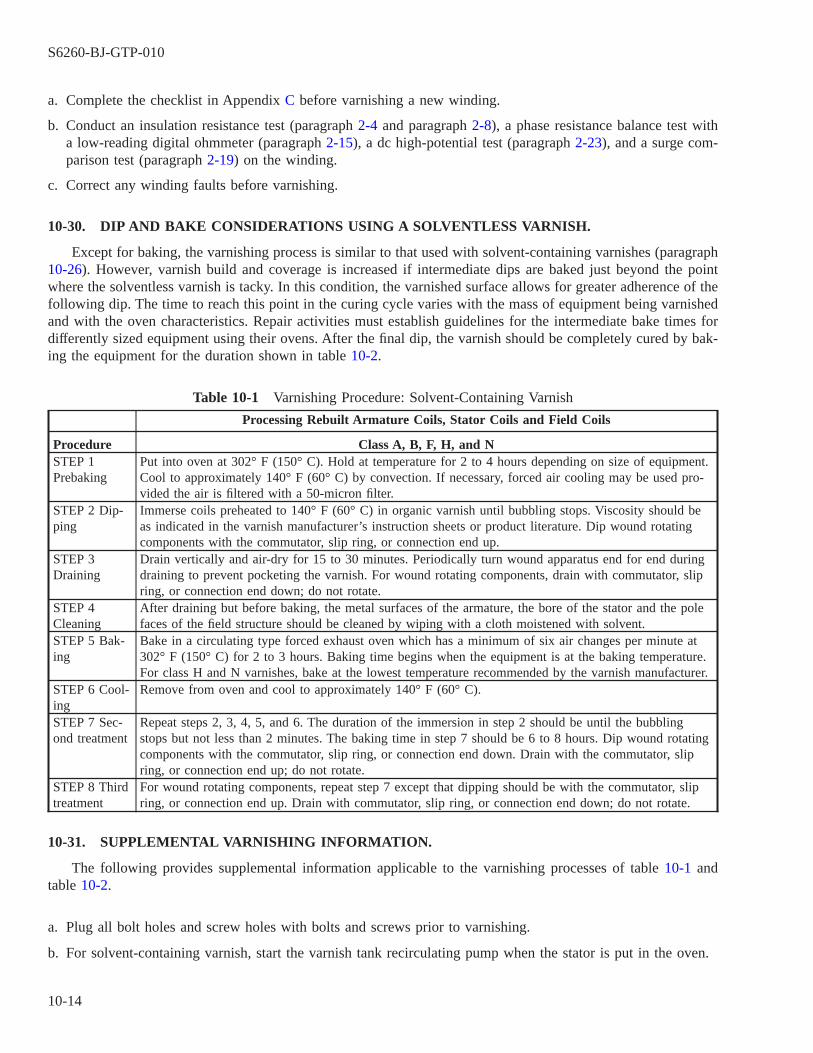
a. Complete the checklist in Appendix C before varnishing a new winding.
b. Conduct an insulation resistance test (paragraph 2-4 and paragraph 2-8), a phase resistance balance test witha low-reading digital ohmmeter (paragraph 2-15), a dc high-potential test (paragraph 2-23), and a surge com-parison test (paragraph 2-19) on the winding.
c. Correct any winding faults before varnishing.
10-30. DIP AND BAKE CONSIDERATIONS USING A SOLVENTLESS VARNISH.
Except for baking, the varnishing process is similar to that used with solvent-containing varnishes (paragraph10-26). However, varnish build and coverage is increased if intermediate dips are baked just beyond the pointwhere the solventless varnish is tacky. In this condition, the varnished surface allows for greater adherence of thefollowing dip. The time to reach this point in the curing cycle varies with the mass of equipment being varnishedand with the oven characteristics. Repair activities must establish guidelines for the intermediate bake times fordifferently sized equipment using their ovens. After the final dip, the varnish should be completely cured by bak-ing the equipment for the duration shown in table 10-2.
Table 10-1 Varnishing Procedure: Solvent-Containing Varnish
Processing Rebuilt Armature Coils, Stator Coils and Field Coils
Procedure Class A, B, F, H, and NSTEP 1Prebaking
Put into oven at 302° F (150° C). Hold at temperature for 2 to 4 hours depending on size of equipment.Cool to approximately 140° F (60° C) by convection. If necessary, forced air cooling may be used pro-vided the air is filtered with a 50-micron filter.
STEP 2 Dip-ping
Immerse coils preheated to 140° F (60° C) in organic varnish until bubbling stops. Viscosity should beas indicated in the varnish manufacturer’s instruction sheets or product literature. Dip wound rotatingcomponents with the commutator, slip ring, or connection end up.
STEP 3Draining
Drain vertically and air-dry for 15 to 30 minutes. Periodically turn wound apparatus end for end duringdraining to prevent pocketing the varnish. For wound rotating components, drain with commutator, slipring, or connection end down; do not rotate.
STEP 4Cleaning
After draining but before baking, the metal surfaces of the armature, the bore of the stator and the polefaces of the field structure should be cleaned by wiping with a cloth moistened with solvent.
STEP 5 Bak-ing
Bake in a circulating type forced exhaust oven which has a minimum of six air changes per minute at302° F (150° C) for 2 to 3 hours. Baking time begins when the equipment is at the baking temperature.For class H and N varnishes, bake at the lowest temperature recommended by the varnish manufacturer.
STEP 6 Cool-ing
Remove from oven and cool to approximately 140° F (60° C).
STEP 7 Sec-ond treatment
Repeat steps 2, 3, 4, 5, and 6. The duration of the immersion in step 2 should be until the bubblingstops but not less than 2 minutes. The baking time in step 7 should be 6 to 8 hours. Dip wound rotatingcomponents with the commutator, slip ring, or connection end down. Drain with the commutator, slipring, or connection end up; do not rotate.
STEP 8 Thirdtreatment
For wound rotating components, repeat step 7 except that dipping should be with the commutator, slipring, or connection end up. Drain with commutator, slip ring, or connection end down; do not rotate.
10-31. SUPPLEMENTAL VARNISHING INFORMATION.
The following provides supplemental information applicable to the varnishing processes of table 10-1 andtable 10-2.
a. Plug all bolt holes and screw holes with bolts and screws prior to varnishing.
b. For solvent-containing varnish, start the varnish tank recirculating pump when the stator is put in the oven.
S6260-BJ-GTP-010
10-14

c. Test the viscosity of solvent-containing varnish after it has been circulated for 1 hour if a weekly test has notbeen conducted. Enter result in the varnish tank log. Solvent-containing varnish viscosity must meet therequirement of table 10-1, step 2.
d. Verify that the solventless varnish has been evaluated by the manufacturer within the appropriate time periodand the recommended corrections have been implemented (refer to paragraph 10-19).
Table 10-2 Varnishing Procedure: Solventless Varnish
Processing Rebuilt Armature Coils, Stator Coils and Field Coils
Procedure Class A, B, F, H, and NSTEP 1 Prebaking Put into oven at 302° F (150° C). Hold at temperature for 2 to 4 hours depending on size of equip-
ment. Cool to approximately 110° F to 120° F (43° C to 49° C) by convection. If necessary, forcedair cooling may be used provided the air is filtered with a 50-micron filter.
STEP 2 Dipping Preheat coils or wound apparatus to 110 to 120° F (43 to 49° C) and immerse in solventless varnishuntil bubbling stops. Viscosity and gel time should be in accordance with the varnish manufactur-er’s recommendation contained in the instruction sheets and product literature provided with thevarnish. Dip wound rotating components with the commutator, slip ring, or connection end up.
STEP 3 Draining Drain vertically and air-dry for 15 to 30 minutes. Periodically turn wound apparatus end for endduring draining to prevent pocketing the varnish. For wound rotating components, drain with com-mutator, slip ring, or connection end down; do not rotate.
STEP 4 Cleaning Before baking, if a masking compound has not been used, the metal surfaces of the armature, thestator bore, and the pole faces of the field structure should be cleaned by wiping with a cloth. Ifpermitted by local environmental regulations, the cloth may be moistened with a solvent.
STEP 5 Baking Bake in a circulating-type forced exhaust oven which has a minimum of six changes of air perminute at 302° F (150° C) until the varnish becomes tacky. For class H and N varnishes, bake atthe lowest temperature recommended by the varnish manufacturer.
STEP 6 Cooling Remove from oven and cool to approximately 110° F to 120° F (43° C to 49° C).STEP 7 Secondtreatment
Repeat steps 2, 3, 4, 5, and 6. The duration of the immersion in step 2 should be until the bubblingstops but not less than 2 minutes. Dip wound rotating components with the commutator, slip ring,or connection end down. Drain in step 3 with the commutator, slip ring, or connection end up; donot rotate.
STEP 8 Thirdtreatment
After the second bake, repeat steps 2, 3, 4, and 5 except that the component orientation during dip-ping and draining should be reversed from that in step 7 and the component should be baked for 6to 8 hours at the temperature indicated in step 5.
S6260-BJ-GTP-010
10-15 / (10-16 Blank)

10-16@@FIpgtype@@BLANK@@!FIpgtype@@
CHAPTER 11
ELECTRICAL TEST, REASSEMBLY, AND FINAL INSPECTION
11-1. SCOPE.
This chapter contains information on motor testing, reassembly, and final inspection. Topics include:
11-1.1 Stator preparation (paragraph 11-2).
11-1.2 Testing the winding (paragraph 11-4).
11-1.3 Checking shaft bearing journals and bearing housing (paragraph 11-6).
11-1.4 Visual inspection of end bells (paragraph 11-8).
11-1.5 Motor assembly (paragraph 11-10).
11-1.6 Final electrical test (paragraph 11-12).
11-2. STATOR PREPARATION.
11-3.
Use the following procedure to prepare the stator for a test of the windings:
a. Remove the winding from the oven after the final bake. Allow it to cool.
b. Use a machinist’s scraper to carefully remove any baked-on varnish from all machined surfaces, including themotor mounting pads. Do not remove metal. The bore should require minimal cleaning if it was wiped witha release agent before dipping.
c. Use a shop vacuum to remove all varnish particles. Do not use compressed air to blow on the windings. Airtends to drive particles into the winding.
11-4. TESTING THE WINDING.
11-5.
Use the following procedures to conduct electrical tests on the windings. Record the results on the motor datasheet (electrical) (figure 11-1).
a. Conduct the following electrical tests:
(1) Ground insulation test (paragraph 2-4 or paragraph 2-8).
(2) Resistance balance test with digital ohmmeter (paragraph 2-15).
(3) Surge comparison test (paragraph 2-19).
(4) AC high potential test (paragraph 2-39 or paragraph 2-45).
(5) Insulation resistance after ac high-potential test (paragraph 2-4 or paragraph 2-8).
b. Enter the results of the tests in section 5 of the motor data sheet (electrical).
S6260-BJ-GTP-010
11-1

c. Set the winding aside after all electrical tests have been completed. Cover the winding to prevent the entry ofdust and dirt.
11-6. CHECKING SHAFT BEARING JOURNALS AND BEARING HOUSINGS.
11-7.
Take the following steps to check the shaft bearing journals and housings:
11-7.1 Fill out another motor data sheet (mechanical) if machine work was necessary to return the shaft bearingareas to specification. The motor data sheet (mechanical) (figure 11-2) must show the reconditioned readings.
11-7.2 Use a snap gage (paragraph 2-62) and appropriate standards to measure the bearing journals. Record thereadings on the motor data sheet (mechanical). Use bore gages (paragraph 2-58) and proper standards to measurehousings. Record the readings on the motor data sheet (mechanical). In the case of bearing seats and housingmeasurements, the positions recorded may not necessarily include maximum and minimum readings. It is impor-tant to locate and measure high spots or low spots caused by ridges, dents, scratches, etc. Record these dimen-sions and their locations on the motor data sheet (mechanical). Compare the readings with the original measure-ments made on the incoming motor.
11-7.3 Measure the radial runout (paragraph 2-53) of the shaft. Record the readings. Return shafts that are outof specification to the machine shop for reworking, or smooth down burrs and ridges with a fine stone or polish-ing paper. Compare the readings with the original measurements made on the incoming motor.
11-8. VISUAL INSPECTION OF END BELLS.
11-9.
Use the following procedure to visually inspect the end bells:
a. Look at the end bell machined surfaces. Pay particular attention to the end bell rabbet and mating housingrabbet. Remove all nicks, burrs, and irregularities before the motor is assembled.
b. Examine nuts, washers, keys, locknuts, and other small hardware. Discard and replace damaged or corrodedcomponents.
S6260-BJ-GTP-010
11-2

Figure 11-1 Motor Data Sheet (Electrical)
S6260-BJ-GTP-010
11-3
11-10. MOTOR ASSEMBLY.
11-11.
To assemble the motor:
a. Select a clean work area large enough to permit easy movement around the motor.
b. Rig chainfalls for handling heavy components. Rig slings to lift the motor.
c. Place the motor frame at a comfortable working height in the clean work area.
d. Assemble all tools and materials.
e. Line the bore of the motor stator with gasket material or with NOMEX to protect the lamination and wind-ings.
S6260-BJ-GTP-010
11-4
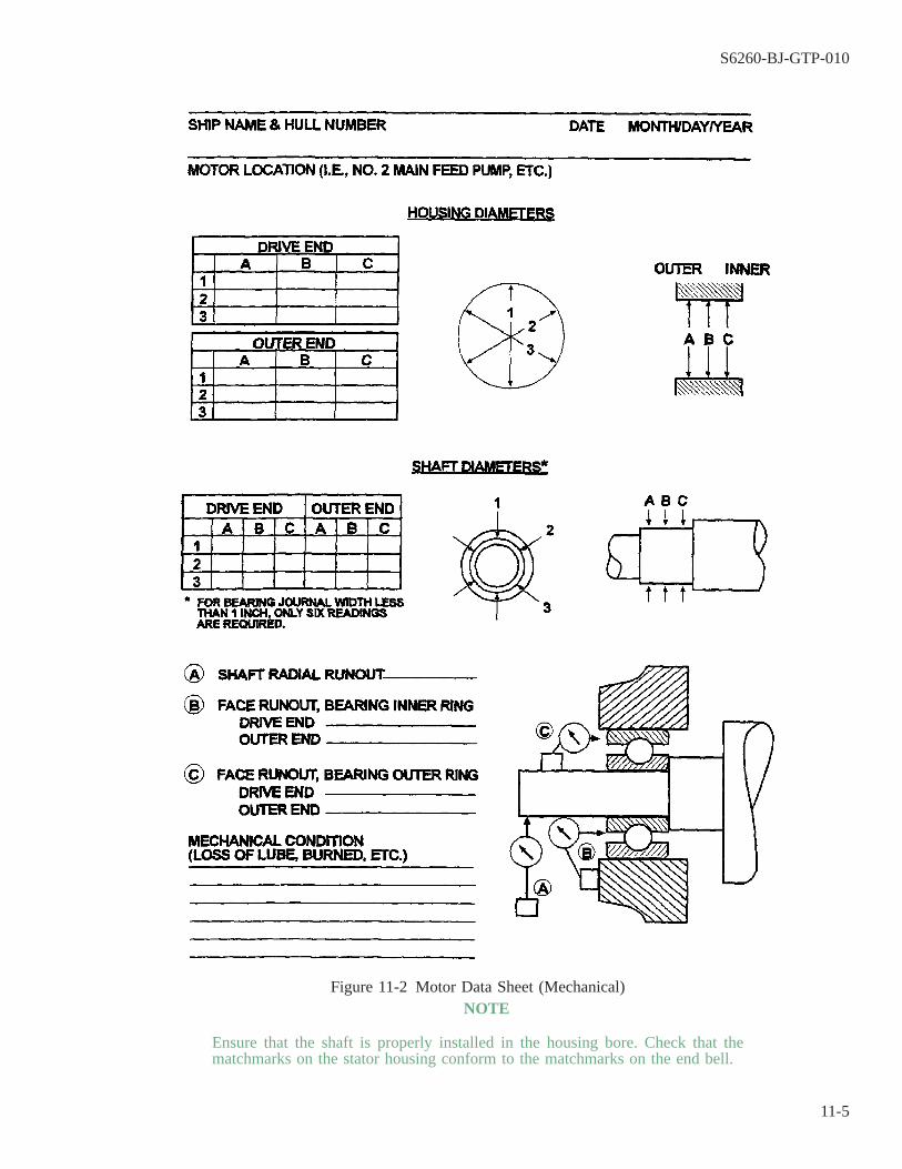
NOTE
Ensure that the shaft is properly installed in the housing bore. Check that thematchmarks on the stator housing conform to the matchmarks on the end bell.
Figure 11-2 Motor Data Sheet (Mechanical)
S6260-BJ-GTP-010
11-5

f. Place the rotor in the bore.
g. Place long studs in the inner bearing cap bolt holes.
h. Position one end bell on or near the shaft. This will allow the studs from the inner bearing cap to be placedthrough the bearing cap retainer bolt holes.
NOTE
Pack open and single-shielded bearings outer bearings caps one-third to one-halffull of grease. Refill lubricated passages with clean grease.
i. Lift the end bell onto the bearing. Align matchmarks. Catch the end bell bolts. Tighten these bolts finger tight.
j. Slide the outer bearing cap into place, using the studs as a guide. Catch the inner bearing cap by installingbolts in two or more vacant holes. Remove studs. Place all bearing cap bolts into position and tighten fingertight.
k. Place studs in the inner bearing cap on the other end of the motor.
l. Place the other end bell on the motor shaft.
m. Support the motor shaft and end bell. Use a pipe slipped over the shaft and an appropriate lifting device.
n. Raise the motor shaft until the rotor is clear of the gasket material or NOMEX protecting the lamination.
o. Remove the packing material or NOMEX from between the rotor and lamination.
p. Slide the end bell toward the motor frame. Insert the inner bearing cap studs through bearing cap bolts onthe end bell.
q. Align the matchmarks.
r. Slide the end bell over the motor bearing and catch the end bell bolts. Tighten them finger tight.
s. Remove the pipe and lifting device.
t. Install the outer bearing cap.
u. Pull the cap up tight. Catch the bearing cap bolts. Tighten them finger tight.
v. Remove the studs. Catch the remaining bearing cap bolts.
w. Check to ensure that the shaft turns freely.
NOTE
Do not completely tighten either end bell in one step. Turn the shaft continuouslywhile tightening.
x. Pull the end bell bolts down in several steps. Use a crisscross pattern, shifting from one end bell to the other.
y. Torque the bolts as shown in table 11-1.
NOTE
Do not completely tighten either bearing cap in one step. Turn the shaft continu-ously while tightening.
z. Tighten the bearing cap bolts. Use a crisscross pattern, shifting from one bearing cap to the other.
aa. Reinstall the balance rings (if applicable).
ab. Check for free rotation of the rotor shaft by hand.
ac. Measure the radial runout of the shaft with a dial indicator. Ensure that total indicated runout is 0.002 inchor less.
S6260-BJ-GTP-010
11-6
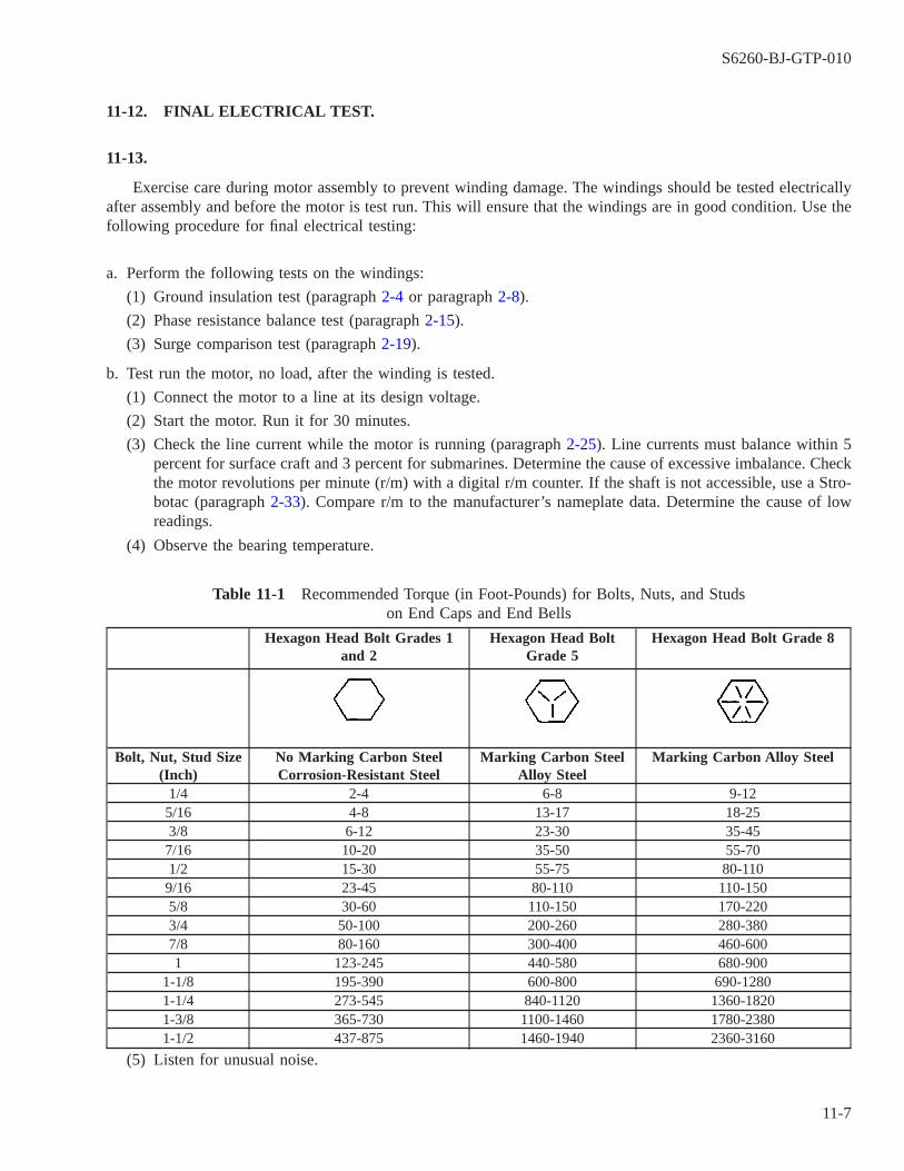
11-12. FINAL ELECTRICAL TEST.
11-13.
Exercise care during motor assembly to prevent winding damage. The windings should be tested electricallyafter assembly and before the motor is test run. This will ensure that the windings are in good condition. Use thefollowing procedure for final electrical testing:
a. Perform the following tests on the windings:
(1) Ground insulation test (paragraph 2-4 or paragraph 2-8).
(2) Phase resistance balance test (paragraph 2-15).
(3) Surge comparison test (paragraph 2-19).
b. Test run the motor, no load, after the winding is tested.
(1) Connect the motor to a line at its design voltage.
(2) Start the motor. Run it for 30 minutes.
(3) Check the line current while the motor is running (paragraph 2-25). Line currents must balance within 5percent for surface craft and 3 percent for submarines. Determine the cause of excessive imbalance. Checkthe motor revolutions per minute (r/m) with a digital r/m counter. If the shaft is not accessible, use a Stro-botac (paragraph 2-33). Compare r/m to the manufacturer’s nameplate data. Determine the cause of lowreadings.
(4) Observe the bearing temperature.
Table 11-1 Recommended Torque (in Foot-Pounds) for Bolts, Nuts, and Studson End Caps and End Bells
Hexagon Head Bolt Grades 1and 2
Hexagon Head BoltGrade 5
Hexagon Head Bolt Grade 8
Bolt, Nut, Stud Size(Inch)
No Marking Carbon SteelCorrosion-Resistant Steel
Marking Carbon SteelAlloy Steel
Marking Carbon Alloy Steel
1/4 2-4 6-8 9-125/16 4-8 13-17 18-253/8 6-12 23-30 35-457/16 10-20 35-50 55-701/2 15-30 55-75 80-1109/16 23-45 80-110 110-1505/8 30-60 110-150 170-2203/4 50-100 200-260 280-3807/8 80-160 300-400 460-6001 123-245 440-580 680-900
1-1/8 195-390 600-800 690-12801-1/4 273-545 840-1120 1360-18201-3/8 365-730 1100-1460 1780-23801-1/2 437-875 1460-1940 2360-3160
(5) Listen for unusual noise.
S6260-BJ-GTP-010
11-7

(6) Check the motor for vibration.
c. Correct all deficiencies before the motor is prepared for return to service.
S6260-BJ-GTP-010
11-8

CHAPTER 12
TRANSPORTATION, INSTALLATION, AND TESTING
12-1. SCOPE.
This section contains information on installing motors. Topics include:
12-1.1 Transporting motors (paragraph 12-2).
12-1.2 Mounting motor to foundation (paragraph 12-4).
12-1.3 Testing motor rotation (paragraph 12-6).
12-1.4 Testing the connection (paragraph 12-9).
12-1.5 Tag-in (paragraph 12-11).
12-1.6 Motor test preparations (paragraph 12-13).
12-1.7 Motor starting and testing (paragraph 2-15).
12-2. TRANSPORTING MOTORS.
12-3. PREVENTING DAMAGE DURING TRANSPORTATION.
Use the following procedures to prevent damage to the motor during transportation:
12-3.1 Bolt a pipe shaft protector over the shaft and to the end bell. This will prevent damage to the motor shaft.
12-3.2 Motors with mounting feet may be transported on a pallet. Inspect the pallet for weakened slats. Do notuse pallets that have been weakened.
12-3.3 Cylindrical motors transported on pallets should be wedged to prevent any movement on the pallet. Nailthe wedges to the pallets to prevent loosening. Band cylindrical motors to the pallet if possible.
12-3.4 All rigging and lifting devices should be positioned to strike the motor below as soon as it is on the ship.Do not leave motors on the weather decks. Refer to Chapter 4 for rigging procedures.
12-4. MOUNTING MOTOR TO FOUNDATION.
12-5.
Use the following procedure to mount a motor to the foundation:
a. Inspect to ensure that there is no:
(1) Corrosion on the mounting bases,
(2) Corrosion or handling damage to the motor or feet, or
(3) Distortion of the foundation due to local welding or cutting operations.
S6260-BJ-GTP-010
12-1

b. It is necessary to have a level foundation in order to do a satisfactory shimming job later. This is true even ifthe foundation is uneven. Perform the following steps to correct an uneven motor base:
(1) Check to ensure that the motor base or feet are flat and in contact with the foundation. All points shouldbe in contact when set on a flat surface. Hand file the surfaces if machining is not possible. Make themas smooth as possible.
(2) Place the assembly on a flat surface. Use a feeler gage to check for high points.
c. Use a flat file to smooth the area where the foundation pads of the motor will rest on the individual pads. Makethe pads as flat as possible. It may not be possible to ensure that they are all the same height, but they mustbe flat.
d. Ensure that the shims, which were removed, marked, and stored during disassembly, are installed correctly.
NOTE
This procedure will be performed by the mechanic during alignment.
e. Set the assembly in place on the foundation. Use a feeler gage to determine the need for additional leveling.Use a file or an appropriate shimming technique when surfaces are not parallel. Good contact must be estab-lished at all fastening points.
12-6. TESTING MOTOR ROTATION.
12-7.
It is necessary to ensure that the motor will have the proper direction of rotation before connecting it to thedriven unit. This should be determined any time that a motor is disconnected and/or reinstalled for any reasonDetermining the direction of motor rotation can normally be accomplished after the motor is set in place butbefore the final shimming, aligning, and tightening down has taken place. The motor is normally then connectedto the controller leads, the circuit is tagged-in and the motor is ″bumped″ or ″jogged″ by the instantaneous push-ing of the controller start and stop buttons. The direction of rotation can then be changed as necessary.
WARNING
Running some types of equipment in the wrong direction may injure person-nel or damage the motor.
12-8.
To conduct a motor direction or rotation test, proceed as follows:
WARNING
Test the voltmeter on a known live circuit before using it to ensure that it isworking properly.
S6260-BJ-GTP-010
12-2

a. Test the controller line (L) leads to ensure that circuit is secured.
b. Determine proper direction of rotation of motor or driven unit by consulting the manufacturers technicalmanual or by observing direction of rotation markings on motor or driven unit.
c. Connect motor leads and controller leads in accordance with existing lead markings if applicable. If the leadsare not tagged and the motor and its power (controller) cable has only three leads, then connect any powerlead to any motor lead.
NOTE
In cases of two-speed dual voltage, consequent pole motors, etc., the motorand/or power cables will have more than three leads. In such cases it will benecessary to consult the manufacturer’s technical manual to determine properconnections as well as possibly identifying individual motor winding and powercable leads by means of continuity testing.
d. Insulate connections in accordance with current directives.
e. Have ship’s force personnel tag-in and energize the circuit.
f. Ensure that all personnel are standing clear of the motor with exception of the person assigned to observe thedirection of motor rotation, if necessary.
g. Push the controller’s start button and instantly press the stop button. Observe and mark the direction of rota-tion with a pencil, marking pen, etc.
h. Compare the actual direction of rotation to the direction required. After ensuring that the circuit has beensecured and tagged out, change direction of rotation on a single-speed motor, if necessary, by reversing anytwo motor leads.
i. Retest direction of rotation as previously described.
j. Have the circuit secured and tagged out when the direction of rotation, is correct.
k. Mark the motor and power cable leads at the motor. Insulate the power leads.
l. Reposition the motor as necessary in preparation for coupling installation.
12-9. TESTING THE CONNECTION.
12-10.
Conduct a ground test from the controller, using a megohmmeter (paragraph 2-4 and paragraph 2-8). Thereading on the controller panel should be at least 2 megohms. Check continuity of the controller cable, motorconnections, and motor windings by reading between the T leads in the controller with a digital ohmmeter (para-graph 2-15).
12-11. TAG-IN.
12-12.
Observe the following procedures for tag-in:
S6260-BJ-GTP-010
12-3

NOTE
See paragraphs 1-22 through 1-29 for a discussion of tag-out and tag-in proce-dures.
a. Tag-in Responsibility. The ship’s force is responsible for tag-in. An authorized representative of the repairactivity must also sign the tag-out record sheet.
WARNING
DANGER:
Closely follow the established ship procedure. High voltages used in opera-tion of electrical equipment can cause DEATH ON CONTACT if personnelignore safety precautions. Use extreme caution when working near thepower source and load components.
b. Tag-in Procedures. Use the following tag-in procedure and the tag-in bill of the tended ship.
NOTE
See OPNAVINST 3120.32, paragraph 630.17, ″Tag-Out Bill,″ for further detailson tag-in.
(1) Ensure that the motor and the equipment that it drives have been properly aligned.
(2) Identify the motor by locating it on the system diagram.
(3) Ensure that all repair work on the entire system to be energized has been completed. Also ensure that themechanical components are completely assembled.
(4) Use a voltmeter to test the line (L) leads in the controller to ensure the circuit is secured.
(5) Notify the proper authorities that tag-in will occur.
(6) Record the tag-in on the tag-out record sheet. Both a ships force and IMA representative must initial thesheet.
(7) Remove all tags and return them to the authorizing officer for destruction.
(8) Observe as appropriate switches or breakers are placed in the energized position.
12-13. MOTOR TEST PREPARATIONS.
12-14.
Before starting the motor, ensure that:
12-14.1 Covers and guards are in place, unless the motor is started for observations requiring their absence.
12-14.2 No one is working on the motor or on the driven unit, if applicable.
S6260-BJ-GTP-010
12-4
WARNING
Running some types of equipment in the wrong direction may injure person-nel or damage the motor.
12-14.3 The motor is connected for the proper direction of rotation.
12-14.4 The motor and driven unit are properly aligned.
12-14.5 Ship’s force personnel responsible for the driven unit are standing by with the system properly alignedif applicable.
NOTE
Submarine motors shall not be connected to the driven load until after a satisfac-tory no-load test is completed.
12-14.6 Ship’s force personnel have conducted all tag-in procedures.
12-14.7 Controller line leads are tested with a voltmeter to ensure that supply voltage is of the proper value andwith no excessive unbalanced condition between phases.
NOTE
Proper voltage for a 440 volt ac installation should be 440 volts ± 22 volts (5percent) with phase unbalance less than 13.2 volts (3 percent).
12-14.8 Cause of voltage supply malfunction has been found and eliminated before test run is conducted.
12-14.9 Appropriate range thermometers have been attached to the bearing housings.
12-15. MOTOR STARTING AND TESTING.
12-16.
Use the following procedure when starting and testing a motor:
CAUTION
Read the operating instructions carefully before starting a motor. Failure tounderstand the instructions may result in unnecessary delay in recognizingabnormal operation. It may also lead to permanent damage to the equip-ment.
S6260-BJ-GTP-010
12-5
a. Have ship’s force personnel start the motor according to instructions in the manufacturers technical manual orthose posted in the controller. Stop the motor immediately and investigate if any unusual noise, vibration,speed, or rise in temperature develops or direction of rotation is incorrect.
b. Conduct a 30-minute test run if conditions appear satisfactory.
c. Check bearing temperatures frequently. Temperatures must not exceed 180°F (68°C).
d. Check frequently to ensure that operation is quiet and vibration free.
e. Measure phase currents using a clamp-on ammeter (see paragraph 2-25).
NOTE
The current in any phase, at rated load, shall not differ from the arithmetic aver-age of the maximum and minimum phase current by more than 10 percent for1-1/2-horsepower (hp) motors or less; by more than 7-1/2 percent for 2- and 3-hpmotors; and by more than 5 percent for motors over 3 hp. For submarine motors,at no load, the maximum deviation of any phase shall not exceed 3 percent ofthe average no-load current.
f. Motors that operate properly within all parameters during the test run will be considered satisfactorily repairedand installed and placed back in commission.
S6260-BJ-GTP-010
12-6
APPENDIX A
SUPPORT DOCUMENTATION AND SOURCES
NOTE
The documents listed in this appendix can be obtained by the command’s tech-nical librarian by using NAVSEA S8800-00-GIP-000, NAVSEA Guidance Hand-book for Intermediate Maintenance Activity Technical Library Personnel. Alwaysensure that the latest edition of a document, with all changes or amendments, isbeing used. Be aware that many of these documents may be online or on cd-romand that these products may no longer be available in microform.
A-1. ALLOWANCE EQUIPAGE LIST (AEL).
Listings by specific categories of allowance items of a durable nature which must be on board for the shipto perform its mission. It includes noninstalled equipage, tools, and special and common support and test equip-ment.
A-2. ALLOWANCE PARTS LIST (APL).
Supply document listing all the parts/data of an individual equipment or component necessary to maintainthat equipment or component in operational condition.
A-3. ALTERATION.
Any change in the hull, machinery, equipment, or fittings which involves a change in design, material, num-ber, location, or relationship of the component parts of an assembly, regardless of whether it is undertaken sepa-rately from, incident to, or in conjunction with repairs. Changes to hull configuration and permanent fittings asa result of changes in machinery, equipage, supplies, or complement are alterations.
A-4. BASIC ALTERATION CLASS DRAWINGS (BACD).
Working drawings prepared by Planning and Overhaul yards or Design Agents for installation of a specificalteration. A BACD is applicable for installation work to the first ship of a class to receive the applicable alter-ation and is generally applicable to all ships in that class.
A-5. BOOKLET OF GENERAL PLANS.
Normally provided to a ship at the termination of an availability period. It is a corrected copy of originaldrawings, showing alterations accomplished and the actual current status of, or conditions existing aboard ship.The booklet is kept by the ship being serviced.
A-6. BUREAU OF SHIPS CONSOLIDATED INDEX OF DRAWINGS, MATERIAL AND SERVICERELATED TO CONSTRUCTION AND CONVERSION (BSCI).
Identifies drawing classification groups based on the functional segment of a ship as represented by a shipstructure, systems, machinery, outfitting, etc. Groups are classified by a system of numeric groupings, or three-digit codes that prefix the seven-digit NAVSHIPS drawing numbers. An additional section lists alphabetically the
S6260-BJ-GTP-010
A-1

noun names for a cross-reference to old BUSHIPS ″S″, groups. The listing is being superseded by the Ships WorkBreakdown Structure (SWBS), limited to new ship construction at this time. (See also entry on Ships WorkBreakdown Structure.)
A-7. COMPONENT IDENTIFICATION NUMBER (CID).
Identification number assigned to an equipment by the Ship Parts Control Center (SPCC). Also called theAPL number.
A-8. COMPOSITE PUBLICATIONS APPLICABILITY LIST (COMPOSITE PAL).
Takes into consideration a class of ships or two or more individual ships and provides a listing of technicalmanuals (TMs) available to support the operation, testing, and maintenance of onboard systems, subsystems, andequipment under the technical cognizance of NAVSEA and SPAWAR (formerly NAVELEX). In addition, theComposite PAL provides a listing of the individual ships for which the equipment and documents are applicable,thereby indicating ships’ equipment commonalities.
A-9. CONSTRUCTION DRAWINGS.
An engineering drawing that illustrates the design of buildings, structures, and related construction, afloat orashore, individually or in groups; and which includes pertinent services, equipment, utilities, and any other engi-neering features, as required, to establish all the interrelated elements of the design. Construction drawings, ingeneral, present design information by pictorial plans, elevations, sections, and details.
A-10. COORDINATED SHIPBOARD ALLOWANCE LIST (COSAL).
Document prepared for an individual ship or shore activity (when it is termed a Coordinated Shore BaseAllowance List, or COSBAL) which lists the equipment or components required for the ship or shore activity toperform its operational assignment; the repair parts and special tools required for the operation, overhaul, andrepair of these equipments; and the miscellaneous portable items necessary for the care and upkeep of the shipor shore activity itself. The COSAL is both a technical and supply document. It is technical in that nomenclature,operating characteristics, TMs, etc., are described on APLs or AELs. It is supply in that the COSAL will providea complete list of all parts required to operate and maintain the ship or shore activity and the equipment installedtherein.
A-11. CROSS REFERENCE INDEX (CRI) OF MANUFACTURERS (VENDORS) EQUIPMENTDRAWINGS.
Relates contractor drawing numbers to an appropriate 35-mm film or reel and frame number from a micro-fiche index. Drawings may then be reproduced in hard copy form. The index is arranged in alphanumericsequence listing by:
A-11.1 Vendor drawing number,
A-11.2 35-mm reel and frame numbers,
A-11.3 Aperture card reference, if applicable.
S6260-BJ-GTP-010
A-2
A-12. DEPARTMENT OF DEFENSE INDEX OF SPECIFICATIONS AND STANDARDS (DODISS).
Published under authority of the Office of the Assistant Secretary of Defense (Manpower, Reserve Affairs,and Logistics) and issued with supplements effective 1 September, 1 November, 1 January, 1 March, and 1 May.The use of this index is mandatory for all military activities. This mandatory provision requires that federal andmilitary specifications, standards, and related standardization documents be considered in identifying items forprocurement actions. Since specifications, standards, and related standardization documents are subject to change,such documents should be reviewed for applicability prior to procurement use. A cumulative alphabetic listing ofspecifications, standards, and related standardization documents, listed by Federal Supply Classification (FSC)Class, is also available from the Naval Publications and Forms Center. The DODISS is comprised of two sepa-rate parts: Part I, which is an alphabetic listing, and Part II, which is a numeric listing. Part II also contains:
A-12.1 Appendix. A cumulative listing of canceled documents, published three times a year. This cumulativelisting of canceled documents is kept current by adding a cumulative cancellation listing of DODISS Part IISupplement and subsequent canceled listing appearing in the basic DODISS, Part II.
A-12.2 Part II, Section ″A″ is a cumulative listing of documents, arranged numerically by document number.Section ″A″ includes the additions and changes to standardization documents listed in Section ″B.″
A-12.3 Part II, Section ″B″ is a ready reference listing of changes, additions, and cancellations to standardiza-tion documents since the previous bimonthly supplement.
A-13. EQUIPAGE.
Specific categories of allowance items of a durable nature, which must be on board for the ship to performits mission. It includes noninstalled equipage, tools, and special and common support and test equipment (seeAEL, paragraph A-1).
A-14. JOINT FLEET MAINTENANCE MANUAL (JFMM).
The JFMM is a standardized basic set of minimum requirements to be used by all type commanders and sub-ordinate commands as a single, unified source of maintenance requirements across all platforms: surface ships,aircraft carriers, and submarines.
A-14.1 It contains clear, concise, technical instructions to ensure that maintenance is planned, executed, com-pleted and documented within all fleet commands. It provides for implementation of regional maintenance poli-cies across all platforms and delivers a comprehensive set of process descriptions fur use by the Navy trainingcommunity. The manual has been in effect since January 1, 1997 and replaces all other maintenance and qualityassurance documents. The JFMM is maintained by the Submarine Maintenance Engineering, Planning, and Pro-curement (SUBMEPP) activity and all recommendations and changes should be submitted to it.
NOTE
Since Part III of Volume 5 is classified, it may not be readily available at allcommands.
A-14.2 The manual is a five-volume set. The volume titles are listed below.
S6260-BJ-GTP-010
A-3

A-14.2.1 Volume I, New Construction,
A-14.2.2 Volume II, Integrated Fleet Maintenance,
A-14.2.3 Volume III, Deployed Maintenance,
A-14.2.4 Volume IV, Tests, Inspections, and Special Application Maintenance Programs, and
A-14.2.5 Volume V, Quality Maintenance (formerly Quality Assurance).
A-15. MULTISHEET DRAWING.
Consists of two or more sheets applicable to the same item. A multisheet drawing is not a type of drawingin the sense of a detail or assembly drawing; rather, the term describes the use of several sheets in presenting allinformation applicable to a single drawing of any one of several types, as opposed to the use of a single roll orflat sheet. Each sheet of a multisheet drawing must be identified by the same drawing number and a differentsheet number.
A-16. NAVAL STOCK LIST OF PUBLICATIONS AND FORMS (NAVSUP PUBLICATION 2002).
Listing of all forms and publications stocked at the Naval Publications and Forms Center. It is the authorityused in requisitioning material. It is divided into 15 main sections based on data types and is updated quarterly.
A-17. NAVCOMPTMAN V-2 (CHAPTER 5 (UIC)).
Listing of Unit Identification Codes (UICs) related to Navy ships, shore stations, and other unit activities. Itis combined with other elements to form organizational identifiers. UICs are required for use with accountingdata, Military Standard Requisitioning and Issue Procedures (MILSTRIP) usage, and contractor activities.
A-18. NAVAL SHIPS TECHNICAL MANUAL (NSTM).
Contains a comprehensive set of instructions for the operation, inspection, and maintenance of a class ofequipment, and other data common to a majority of installations. Each chapter covers a specific subject and iscomplete in itself. Included are approximately 100 different subjects, ranging from boilers and pumps to flags andbunting.
A-19. PLANNING AND ENGINEERING FOR REPAIRS AND ALTERATIONS (PERA).
An engineering management organization whose mission is to act as NAVSEA’s principal management agentin providing integrated planning and engineering for overhauls of its assigned ship types. Responsibilities includeintegrating the requirements of various Systems Commands and the Fleet. PERAs manage the planning and engi-neering efforts for designated ship overhauls and pertinent vital interrelated programs.
A-20. PLANNING YARD.
The Naval Shipyard or other activity designated by NAVSEA to perform the following tasks pertaining tospecifically assigned ships:
A-20.1 Providing or coordinating the provision of technical and other services in design matters.
S6260-BJ-GTP-010
A-4

A-20.2 Preparation and availability of complete up-to-date files of BACDs, ship selected records (SSR), andworking drawings.
A-20.3 Custody and maintenance of all original ship drawings and 35-mm aperture cards (Type I Class I) ofdrawings.
A-20.4 Providing a central repository, reproduction facility, and distribution services, or coordinating such ser-vices, from the original or master copies of working drawings, BACD, and SSR.
A-21. PUBLICATIONS APPLICABILITY LIST (PAL).
Listing of technical manuals (TMs) available to support the operation, testing, and maintenance of onboardsystems, subsystems, and equipments under the technical cognizance of NAVSEA and SPAWAR. The PAL is tai-lored specifically to the ship indicated and is intended to serve as a tool to assist in the inventory determinationof shipboard-required TMs. Since the information contained in the PAL is only as good as that provided byreporting technical activities or system users, some omissions and errors may be noted. If discrepancies aredetected, marked-up pages with recent changes may be returned to the preparing activity (NSWSES Code 5700)for resolution. A revised PAL reflecting the changes will be provided within 60 days. The PAL consists of fourvolumes:
A-21.1 Volume I (General) provides a convenient listing of all nonsystem or equipment-related technical manu-als (e.g., Ship Information Books, Damage Control Books, Communications Handbooks, etc.) for electronics;hull, mechanical, and electrical; and ordnance.
A-21.2 Volume II (Electronic and Electronic Test Equipment) contains data relating to electronic and elec-tronic test equipment. The equipment sequence section permits checking by system and/or equipment designator(e.g., Radar Set AN/SPS-4), and provides a list of the available TMs for the system and/or equipment. A docu-ment sequence section is also included to provide a total listing of available system and equipment TMs. Equip-ment listed in this volume was obtained form the Ship Equipment Configuration Accounting System (SECAS I).Reported equipment discrepancies will be resolved by NAVSEA with SECAS.
A-21.3 Volume III (Hull, Mechanical, and Electrical) contains two sequences as described in II above. Simi-larly, in the equipment sequence section, a check can be made by system or equipment designator (e.g., Dish-washer Model 250 DA) to identify a list of the available TMs. Here again, the document sequence section pro-vides a total listing of available system and equipment TMs. Equipment listed in this volume was obtained fromrecords maintained by the Ship Technical Data Management Information System (STEDMIS) pending the imple-mentation of SECAS III for hull, mechanical, and electrical systems and equipment.
A-21.4 Volume IV (Ordnance) contains the data listed in the former Publication Requirement List of TMs(Ordnance Pamphlets, Ordnance Data, Field Manuals, TMs, and Ordnance Supply Office Illustrated Parts Break-down) required to support the operation and maintenance of onboard ordnance systems, equipments, and relateditems.
A-22. SELECTED RECORD DRAWINGS.
Important basic technical information and related data relative to certain shipboard arrangements, equipment,and systems under NAVSEA cognizance. It is selected for its value as a reference for consulting purposes, and
S6260-BJ-GTP-010
A-5

for the Ship Operating Forces, Planning Yards, Overhaul Yards, and other concerned activities. The Ship LifeCycle Management Support Manual gives a listing of the types of data to be included.
A-23. SHIP WORK BREAKDOWN STRUCTURE (SWBS) (NAVSEA 0900-LP-039-9010).
Single language which can be used through the entire ship life cycle from early design through productionand subsequent layup. The objective of SWBS is to combine into a single system the function formerly servedby the following numbering systems:
A-23.1 Bureau of Ships Consolidated Index of Drawings (BSCI). This three-digit numeric system had been usedfor cost and weight estimating and reporting, progress reporting for new construction and conversion ships, anddrawing numbering. This was the basic numbering system used by Naval Shipyards for work scheduling andcontrol of ship availabilities. (See also entry on Bureau of Ships Consolidated Index of Drawings, paragraphA-6.)
A-23.2 Ship Design and Material, Group 9000 series, of the Navy Subject Identification Codes (SSIC). Thisfour-digit numeric system was used for correspondence and filing technical document numbering sections of ShipSpecifications. It was based on the former BUSHIPS ″S″ group system by changing the ″S″ to a ″9.″
A-24. SHIP CONSTRUCTION DRAWINGS (SCD).
Original drawings used for ship construction; they originate with the Planning Yard. Portions of these draw-ings may be maintained by an individual ship as Selected Record Drawings pertaining to specific installations.They are available in aperture card form.
A-25. SHIP DRAWING INDEX (SDI).
List of ship drawings and related design reference information which shows the actual current configurationof the ship. SDIs are required by the General Specifications for Shipbuilding for all ships over 200 feet in length.The original SDI is prepared by the shipbuilder in accordance with the Detailed Ship Specification as approvedby the Supervisor of Shipbuilding (SUPSHIP).
After acceptance of the ship by the Navy, the SDI is forwarded to the selected Planning Yard which isassigned as custodian of the index. Corrections to the SDI are made by the Overhaul Yard to reflect work per-formed during yard periods and tender overhaul. Original SDIs are to be corrected by the Planning Yard to reflectchanges reported by the ship or other activity when changes are made between regular overhauls. Informationprovided by the SDI includes:
A-25.1 Drawing title,
A-25.2 NAVSEA drawing number and revision, and
A-25.3 Builder’s or contractor’s drawing numbers of hull machinery, electrical, and electronic drawings appli-cable to the individual ships.
S6260-BJ-GTP-010
A-6
A-26. SHIP INFORMATION BOOKS (SIBs).
Part of the Selected Record Data required aboard ships. They are updated during availability periods and arein the custody of the ships being serviced. SIBs normally comprise a seven-volume set, broken down into spe-cific systems and subsystems.
A-27. SHIP’S SYSTEM MANUALS (SSM).
Similar to SIBs, but with expanded technical information. SSMs are used on all submarines and certain sur-face ships in lieu of SIBs.
A-28. TECHNICAL MANUALS.
Publications and other forms of documentation containing a description of ships, boats, amphibious vehicles,systems, or equipment, with instructions for effective use, including one or more of the following sections asrequired: instructions covering initial preparation and installation; operating instructions; maintenance instruc-tions; overhaul instructions; parts listing; and related technical information or procedures exclusive of those pro-cedures of an administrative or tactical nature.
A-29. TECHNICAL REPAIR STANDARD (TRS).
Establishes requirements for the overhaul or refurbishment of a system, equipment, or component. It speci-fies in detail the inspections, measurements, tolerances, material, work, tests, and quality assurance operationsrequired to restore the item to a condition that will ensure its satisfactory service for a limited period of time,during which only routine maintenance will be required.
A-30. VENDOR DRAWINGS (HULL, MECHANICAL AND ELECTRICAL).
Prepared by the manufacturer or contractor at the time of construction or original installation of equipment.In many instances, these drawings are not of sufficient detail and may not be currently updated. Drawings maybe obtained for hull, mechanical, and electrical requirements. Sufficient lead time should be allowed for procure-ment.
A-31. VENDOR CROSS-REFERENCE INDEX (VCRI).
An index published by the Portsmouth Naval Shipyard which cross reference the drawing number of hull,mechanical, and electrical drawings to a reel and frame number for vendor drawings previous to 1965. It alsoindicates that a newer drawing is available on aperture cards.
S6260-BJ-GTP-010
A-7 / (A-8 Blank)

A-8@@FIpgtype@@BLANK@@!FIpgtype@@

APPENDIX B
SPECIFIC REFERENCES
NOTE
Ensure that the latest edition of a document is available, including any changes.
B-1. NAVY PUBLICATIONS
CINCLANTFLT/CINCPACFLTINST4790.3
Joint Fleet Maintenance Manual
NAVEDTRA 10101 Boatswain’s Mate, Volume 1NAVSEA S8800-00-GIP-000 NAVSEA Guidance Handbook for Intermediate Maintenance Activity Technical
Library PersonnelNAVSEA S9086-HN-STM-010/CH244
Naval Ships’ Technical Manual, ″Bearings and Seals″
NAVSEA S9086-HT-STM-010/CH262
Naval Ships’ Technical Manual, ″Lubricating Oils, Greases, Hydraulic Fluids,and Lubricating Systems″
NAVSEA S9086-KC-STM-010/CH300
Naval Ships’ Technical Manual, ″Electric Plant, General″
NAVSEA S9086-KE-STM-010/CH302
Naval Ships’ Technical Manual, ″Electric Motors and Controllers″
NAVSEA S9086-UU-STM-010/CH613
Naval Ships’ Technical Manual, ″Rope and Rigging″
NAVSEA S9810-AA-GTP-101/IMA Naval Ships’ Intermediate Maintenance Activity (IMA) Workcenter RequirementsManual
OPNAVINST 3120.32 Standard Organization and Regulations of the U.S. NavyOPNAVINST 4790.4C Ships’ Maintenance Material Management (3M) Manual
B-2. SPECIFICATIONS
DOD-STD-2182 Engineering Chromium Plating (Electrodeposited) for Repair of Shafting (Met-ric)
FF-B-171 Bearings, Ball, Annular (General Purpose)J-W-1177 Wire, Magnet, ElectricalMIL-STD-102 Anti-Friction Bearing Identification CodeMIL-STD-2197 Brush Electroplating on Marine MachineryMIL-B-17931 Bearings, Ball, Annular, for Quiet OperationMIL-C-16173 Corrosion Preventive Compound, Solvent Cutback, Cold-applicationMIL-D-12182 Powdered Saltwater SoapMIL-D-16791 Non-Ionic DetergentMIL-I-631 Insulation, Electrical, Synthetic-resin Composition, NonrigidMIL-I-695 Insulation, Electrical, Paper (Slot Cell)MIL-I-3190B Insulation Sleeving, Electrical, Flexible, TreatedMIL-I-003190C Insulation Sleeving, Electrical, Flexible, Coated, General Specification forMIL-I-3505 Insulation Sheet and Tape, Electrical, Coil and Slot, High TemperatureMIL-I-21070 Insulation Sheet and Tape, Electrical, Reinforced Mica PaperMIL-I-21557 Insulation Sleeving, Electrical, Flexible, Glass Fiber, Vinyl Treated
S6260-BJ-GTP-010
B-1

MIL-I-22834 Insulation, Electrical, Dielectric, Barrier, Laminated, Plastic Film and SyntheticFiber Mat
MIL-I-24092 Insulating Varnish, Electrical, Impregnating, Solvent ContainingMIL-L-24204 Insulation, Electrical, High Temperature, Bonded, Synthetic Fiber PaperMIL-L-43435 Tape, Lacing and TyingMIL-L-HDBK-203 Manufacturers’ Symbols and Designations for Anti-Friction BearingsMIL-P-997 Plastic Material, Laminated, Thermosetting, Electric Insulation, Sheets, Glass
Cloth, Silicone Resin.MIL-P-15037 Plastic Sheet, Laminated, Thermosetting, Glass-cloth, Melamine-resinMIL-T-713 Twine, Fibrous, Impregnated, Lacing and TyingMIL-T-15126 Insulation Tape, Electrical, Pressure Sensitive Adhesive and Pressure Sensitive
Thermosetting AdhesiveMIL-T-19166 Insulation Tape, Electrical, High-temperature, Glass Fiber, Pressure-sensitiveMIL-W-16878 Wire, Electrical Insulated, High Temperature (Navy)MIL-Y-1140 Yarn, Cord, Sleeving, Cloth, and Tape-GlassP-D-220 Detergent, General PurposeP-D-680 Dry Cleaning Solvent
B-3. LUBRICATING OILS AND BEARING GREASE
DOD-G-24508 Grease, High Performance, Multipurpose
MIL-G-24139 Grease, Multipurpose, Water ResistantMIL-G-81322 Grease, Aircraft, General Purpose, Wide Temperature RangeMIL-L-15719 Lubricating Grease, High Temperature, Electric Motor, Ball and Roller BearingsMIL-L-17331 Lubricating Oil, Steam Turbine and Gear, Moderate Service, Military Symbol
2190 TEP
S6260-BJ-GTP-010
B-2

APPENDIX C
MOTOR WINDING CHECKLIST
C-1. SCOPE.
This appendix is a checklist for use when rewinding motors.
C-2 BEFORE WINDING. Check to ensure that:
C-2.1 The stator core is clean, and that burrs are removed from slots and other areas.C-2.2 Correct materials are available, such as magnet wire; ground, phase, and wedge insulation; coil separators; tiecord; lead wire; sleeving; and varnish.C-2.3 The coils are correctly made.C-2.4 The coil dimensions shown in the applicable drawing are correct.C-2.5 The magnet wire enamel on coils has no nicks or abrasions; discard damaged coils.
C-3 DURING WINDING. Check to ensure that:C-3.1 The proper coil span is used.C-3.2 The slot cell extension beyond the core is at least 3/8 inch on each side.C-3.3 Slot wedges are not forced into place and insulation is not damaged in the process.C-3.4 Slot wedges are not cocked or loose, and that they securely hold the windings.C-3.5 The coil ends are cleaned and tinned before soldering.C-3.6 The lead wire has the same current capacity as the original.C-3.7 End turns and connections on both ends are back clear of the line from the stator bore so that they will notinterfere with installation of the rotor, and that there is no interference with end bells or air shields.C-3.8 The leads are properly marked and mechanically secure to prevent movement.C-3.9 All connections are solidly made and are of good quality.C-3.10 All connections are properly insulated.C-3.11 Tags on leads do not cut through insulation.C-3.12 Coil separators extend 1/4 inch beyond the slot cell to allow phase insulation to lap it.C-3.13 Coil separators extend the full width of the slot so that coils are separated.C-3.14 The phase insulation is located properly between phase groups. It must extend to the slot cell and lap eitherabove or below the coil separator.
C-4 AFTER WINDING AND BEFORE VARNISHING.C-4.1 Observe the following guidelines:
a. Measure the winding resistance (paragraph 2-15) from phase to phase. Record.b. Measure the insulation resistance (paragraph 2-4 or paragraph 2-8) from windings to ground. Record.c. Conduct a dc high-potential test on the winding (paragraph 2-23 or paragraph 2-45).d. Ensure that the leads are properly marked.e. Test the winding with a surge comparison tester (paragraph 2-19).f. Check for reversed coil or phase, and for shorted turns or phases.g. Test the windings for continuity with a low-reading digital ohmmeter (paragraph 2-15).h. Check that wires do not overlap the phase insulation.
C-4.2 Ensure thatC-4.2.1 The phase insulation extends beyond end turns (approximately 1/8 inch).C-4.2.2 Connections are electrically sound and neat.C-4.2.3 Wedges are properly positioned and snug.C-4.2.4 The phase insulation is fully inserted to meet the slot cell.C-4.2.5 The slot cell extends uniformly 3/8 inch past the core.C-4.2.6 Tie cords are tight and secured.C-4.2.7 The slot cell material is not torn or damaged.C-4.2.8 Windings are not damaged.
S6260-BJ-GTP-010
C-1

C-4.2.9 Poor workmanship (sloppy appearance) is corrected.C-4.2.10 Bolts have been inserted in all threaded holes.
C-5 VARNISH, SOLVENT-CONTAINING. Check to ensure thatC-5.1 Viscosity and temperature are correct.C-5.2 Do not use varnish which has passed the expiration date in the varnish log tank unless it has been retested.
C-6 AFTER DIPPING IN VARNISH AND BEFORE BAKING. Ensure that:C-6.1 Windings are clear and smooth, with good bonding and filling.C-6.2 Varnish buildup is uniform over the entire winding surface.C-6.3 Varnish drippings are not excessive.C-6.4 Wedges are properly positioned.C-6.5 Varnish is removed from the bore of the stator and machined surfaces.
C-7 AFTER BAKING. Ensure that:C-7.1 Varnish is not cracked and there are no air bubbles.C-7.2 Varnish is not soft or tacky to the touch (improper varnish cure).C-7.3 Wires are bonded in place by varnish.C-7.4 Windings are not damaged.
S6260-BJ-GTP-010
C-2

APPENDIX D
IDENTIFICATION OF WINDINGS
D-1. SCOPE.
This appendix outlines the characteristics of single-phase and three-phase windings.
D-2. CLASSIFICATION OF AC WINDINGS AND SOME FUNDAMENTAL CONCEPTS.
D-3. COIL GROUP, COIL, TURN, CONDUCTOR, AND STRAND.
Each winding consists of a number of coils arranged in coil groups; each coil group may have one or moresingle coils. A coil consists of one or more turns connected in series; each turn consists of one or more individualconductors, in parallel, wrapped through 360 physical degrees.
D-4. ONE- AND THREE-PHASE WINDINGS.
AC windings are single-phase or three-phase, corresponding to the number of phases of the power source towhich they are connected. In three-phase windings, the slots per pole are divided into two or three parts, one partfor each phase. The number of slots per pole is determined by the total number of slots and the number of poles.The number of poles is determined by the number of cycles and the speed.
D-5. CYCLE AND FREQUENCY.
A period is the time necessary for an alternating current to change from one positive maximum to the nextfollowing positive maximum. During this time, the alternating current goes through a complete cycle, i.e., itaccepts all possible positive as well as negative values. Power lines in the United States carry current at 60 cyclesper second (c/s). The number of cycles per second is called frequency . Frequency is measured in Hertz (Hz),with 1 Hz = 1 c/s.
D-6. NUMBER OF POLES, SYNCHRONOUS SPEED.
The number of poles is determined by the following rule:
No. of Poles = 120 x Frequency/Speed (in revolutions per minute (r/m))
It follows that:
Speed (in r/m) = 120 x Frequency/No. of Poles
The speed obtained form this equation is called synchronous speed . A synchronous generator or motor runsat exactly synchronous speed. The actual speed of the rotor of an induction motor is somewhat below the syn-chronous speed.
S6260-BJ-GTP-010
D-1

D-7. POLE-PHASE GROUP.
The coils lying in slots that belong to one phase and that are under one pole, i.e., the coils lying in CPG (seeparagraph D-8) slots, make a coil group, which is called a pole-phase group. The total number of pole-phasegroups is determined by the number of poles and the number of phases. Thus:
No. of Pole-Phase Groups = No. of Poles x No. of Phases and the number of single coils per pole-phase groupis equal to the CPG.
D-8. COILS PER POLE PER PHASE.
As already mentioned, the number of coils per pole for three-phase windings is divided into three parts. Thenumber of coils per pole per phase is, therefore, equal to the number of phases or to the total number of coilsdivided by the number of poles and times the number of phases. The number of coils per pole per phase is animportant quantity in the layout of ac windings. The symbol CPG will be used for this quantity. Thus:
CPG = Total No. of Slots/(No. of Poles) x (No. of Phases)
D-9. COIL PITCH.
The coil pitch, or span, is equal to the number of slots separating the sides of a coil, including the slots inwhich the winding lies.
D-10. CLASSIFICATION OF AC WINDINGS.
AC windings may also be classified in several other ways:
D-10.1 Single-layer or two-layer windings (figure D-1).
S6260-BJ-GTP-010
D-2

D-10.2 Semi-closed slot or open slot (figure D-2).
D-10.3 Chain or distributed (figure D-3).
D-10.4 Single phase or polyphase.
D-10.5 Round or rectangular wire section.
D-10.6 Lap or wave.
D-10.7 Star or delta.
D-10.8 Full-pitch or fractional-pitch (figure D-4).
D-10.9 Integral-slot or fractional-slot.
Figure D-1 Single- and Two-Layer Windings
S6260-BJ-GTP-010
D-3
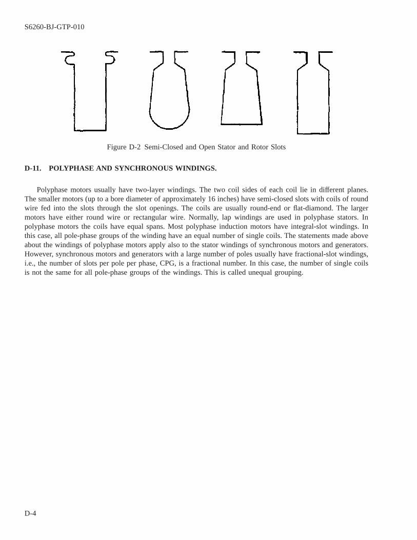
D-11. POLYPHASE AND SYNCHRONOUS WINDINGS.
Polyphase motors usually have two-layer windings. The two coil sides of each coil lie in different planes.The smaller motors (up to a bore diameter of approximately 16 inches) have semi-closed slots with coils of roundwire fed into the slots through the slot openings. The coils are usually round-end or flat-diamond. The largermotors have either round wire or rectangular wire. Normally, lap windings are used in polyphase stators. Inpolyphase motors the coils have equal spans. Most polyphase induction motors have integral-slot windings. Inthis case, all pole-phase groups of the winding have an equal number of single coils. The statements made aboveabout the windings of polyphase motors apply also to the stator windings of synchronous motors and generators.However, synchronous motors and generators with a large number of poles usually have fractional-slot windings,i.e., the number of slots per pole per phase, CPG, is a fractional number. In this case, the number of single coilsis not the same for all pole-phase groups of the windings. This is called unequal grouping.
Figure D-2 Semi-Closed and Open Stator and Rotor Slots
S6260-BJ-GTP-010
D-4

D-12. INSULATION OF THE WIRE AND THE SLOTS OF THE STATOR.
Single cotton-covered enamel wire, as well as plain enamel wire, is used for the wire insulation of smallsingle-phase motors. Where the space permits, single cotton-covered enamel wire is preferred.
D-13. LOCATION OF THE BEGINNINGS OF THE PHASES.
The beginnings of the phases lie one pole-phase group apart. They are either the starts or the finishes of twoconsecutive pole-phase groups. Since there are three pole-phase groups per pole, the beginnings of the phases liein slots which are half a pole-pitch apart. The ends of the phases also lie half a pole-pitch apart. This rule isapplicable for a series as well as for any kind of parallel connection.
Figure D-3 Chain and Distributed Windings
S6260-BJ-GTP-010
D-5

D-14. DUAL-VOLTAGE CONNECTIONS.
Small motors, up to approximately 15 hp, are usually designed by the manufacturer so that they may be usedfor two or more different voltages. For example, a winding may be laid out to have a series connection for 220volts and a two-parallel connection for 110 volts; or a series connection for 440 volts and a four-parallel connec-tion for 110 volts. The change from one voltage to the other is simplified when extra leads are brought out. Alldual-voltage windings must have nine leads per winding.
D-15. LAYOUT OF THREE-PHASE WINDINGS.
The slots belonging to one pole of a three-phase winding are divided into three parts corresponding to thenumber of phases; there are three pole-phase groups per pole. Two consecutive groups belonging to the samephase are two pole-phase groups apart. The number of pole-phase groups can be determined using the followingequation:
No. of Pole-Phase Groups = No. of Poles x No. of Phases
Thus, in the case of a four-pole winding, the number of pole-phase groups is equal to 4 x 3 = 12. Figure D-5shows the 12 groups. They, are numbered clockwise. Groups 1,4,7, and 10 belong to phase A; groups 2, 5, 8, and11, to phase C; and groups 3, 6, 9, and 12, to phase B. The groups belonging to phase A are shown as heavy line,the groups belonging to phase B as dotted lines, and the groups belonging to phase C as light solid lines. Sincetwo consecutive pole-phase groups of the same phase lie under poles of different polarity, the arrows assigned tothem must have different directions. Therefore, the arrow of group 4 is opposite to the arrow of group 1, thearrow of group 7 opposite that of group 4, etc. As for the two-phase winding, the series connection of two con-secutive pole-phase groups of the same phase may be accomplished by connecting either their finishes or theirstarts together, while for the parallel connection of these same two consecutive pole-phase groups, the start ofone pole-phase group must be connected with the finish of the other pole-phase group.
Figure D-4 Full-Pitch and Fractional Pitch Windings
S6260-BJ-GTP-010
D-6
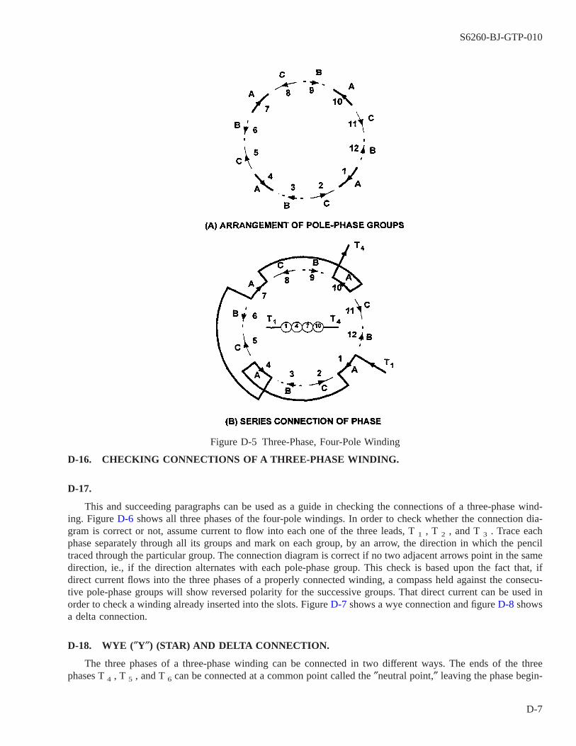
D-16. CHECKING CONNECTIONS OF A THREE-PHASE WINDING.
D-17.
This and succeeding paragraphs can be used as a guide in checking the connections of a three-phase wind-ing. Figure D-6 shows all three phases of the four-pole windings. In order to check whether the connection dia-gram is correct or not, assume current to flow into each one of the three leads, T 1 , T 2 , and T 3 . Trace eachphase separately through all its groups and mark on each group, by an arrow, the direction in which the penciltraced through the particular group. The connection diagram is correct if no two adjacent arrows point in the samedirection, ie., if the direction alternates with each pole-phase group. This check is based upon the fact that, ifdirect current flows into the three phases of a properly connected winding, a compass held against the consecu-tive pole-phase groups will show reversed polarity for the successive groups. That direct current can be used inorder to check a winding already inserted into the slots. Figure D-7 shows a wye connection and figure D-8 showsa delta connection.
D-18. WYE (″Y″) (STAR) AND DELTA CONNECTION.
The three phases of a three-phase winding can be connected in two different ways. The ends of the threephases T 4 , T 5 , and T 6 can be connected at a common point called the ″neutral point,″ leaving the phase begin-
Figure D-5 Three-Phase, Four-Pole Winding
S6260-BJ-GTP-010
D-7
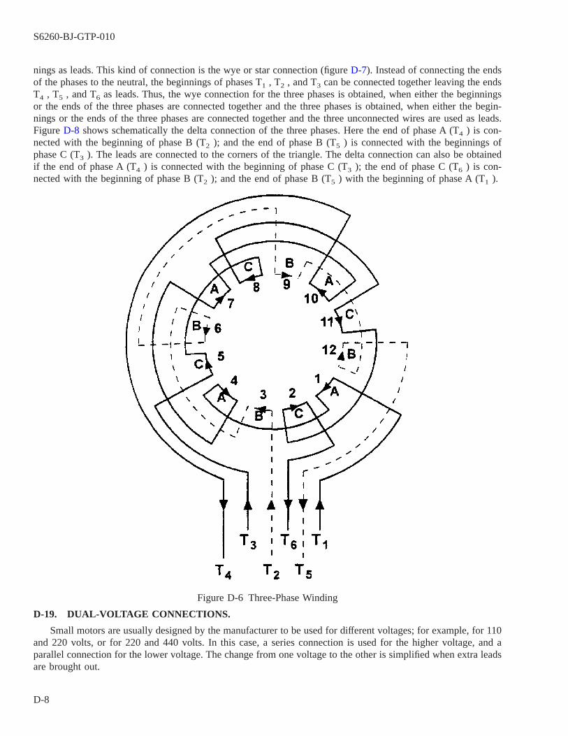
nings as leads. This kind of connection is the wye or star connection (figure D-7). Instead of connecting the endsof the phases to the neutral, the beginnings of phases T1 , T2 , and T3 can be connected together leaving the endsT4 , T5 , and T6 as leads. Thus, the wye connection for the three phases is obtained, when either the beginningsor the ends of the three phases are connected together and the three phases is obtained, when either the begin-nings or the ends of the three phases are connected together and the three unconnected wires are used as leads.Figure D-8 shows schematically the delta connection of the three phases. Here the end of phase A (T4 ) is con-nected with the beginning of phase B (T2 ); and the end of phase B (T5 ) is connected with the beginnings ofphase C (T3 ). The leads are connected to the corners of the triangle. The delta connection can also be obtainedif the end of phase A (T4 ) is connected with the beginning of phase C (T3 ); the end of phase C (T6 ) is con-nected with the beginning of phase B (T2 ); and the end of phase B (T5 ) with the beginning of phase A (T1 ).
D-19. DUAL-VOLTAGE CONNECTIONS.
Small motors are usually designed by the manufacturer to be used for different voltages; for example, for 110and 220 volts, or for 220 and 440 volts. In this case, a series connection is used for the higher voltage, and aparallel connection for the lower voltage. The change from one voltage to the other is simplified when extra leadsare brought out.
Figure D-6 Three-Phase Winding
S6260-BJ-GTP-010
D-8
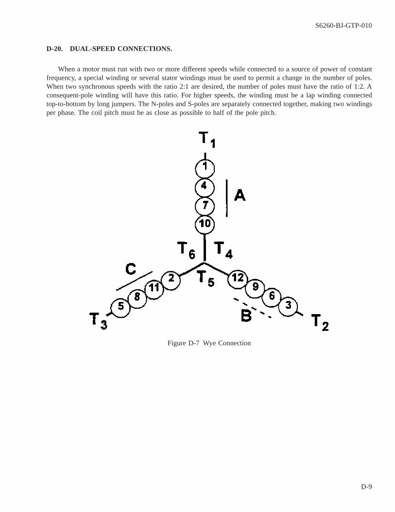
D-20. DUAL-SPEED CONNECTIONS.
When a motor must run with two or more different speeds while connected to a source of power of constantfrequency, a special winding or several stator windings must be used to permit a change in the number of poles.When two synchronous speeds with the ratio 2:1 are desired, the number of poles must have the ratio of 1:2. Aconsequent-pole winding will have this ratio. For higher speeds, the winding must be a lap winding connectedtop-to-bottom by long jumpers. The N-poles and S-poles are separately connected together, making two windingsper phase. The coil pitch must be as close as possible to half of the pole pitch.
Figure D-7 Wye Connection
S6260-BJ-GTP-010
D-9

D-21. TABULAR TYPES.
A connection diagram for the four-pole, three-phase, series wye connection is shown in figure D-9; for thefour-pole, three-phase, two parallel wye connection in figure D-10; for the four-pole, three-phase, series deltaconnection in figure D-11; and for the four-pole, three-phase, two-parallel delta connection in figure D-12.
Figure D-8 Delta Connection
S6260-BJ-GTP-010
D-10
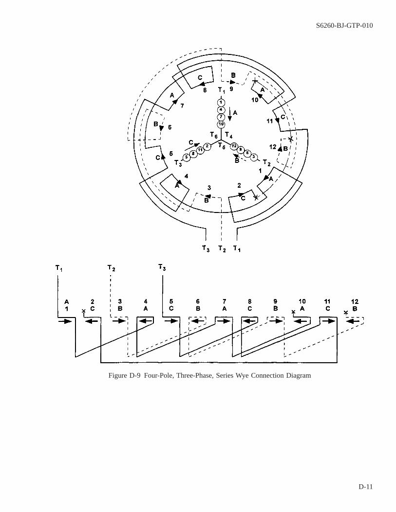
Figure D-9 Four-Pole, Three-Phase, Series Wye Connection Diagram
S6260-BJ-GTP-010
D-11
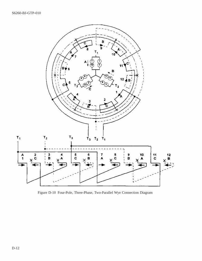
Figure D-10 Four-Pole, Three-Phase, Two-Parallel Wye Connection Diagram
S6260-BJ-GTP-010
D-12
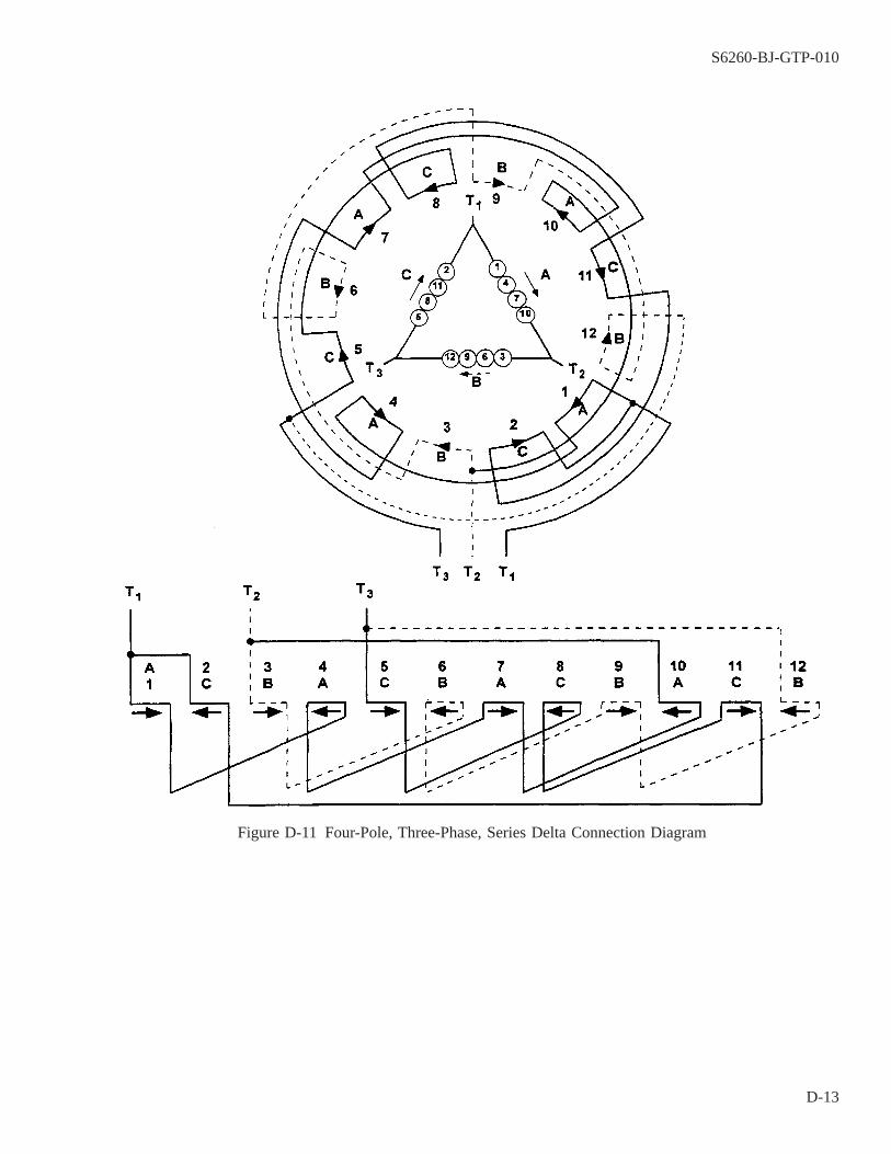
Figure D-11 Four-Pole, Three-Phase, Series Delta Connection Diagram
S6260-BJ-GTP-010
D-13
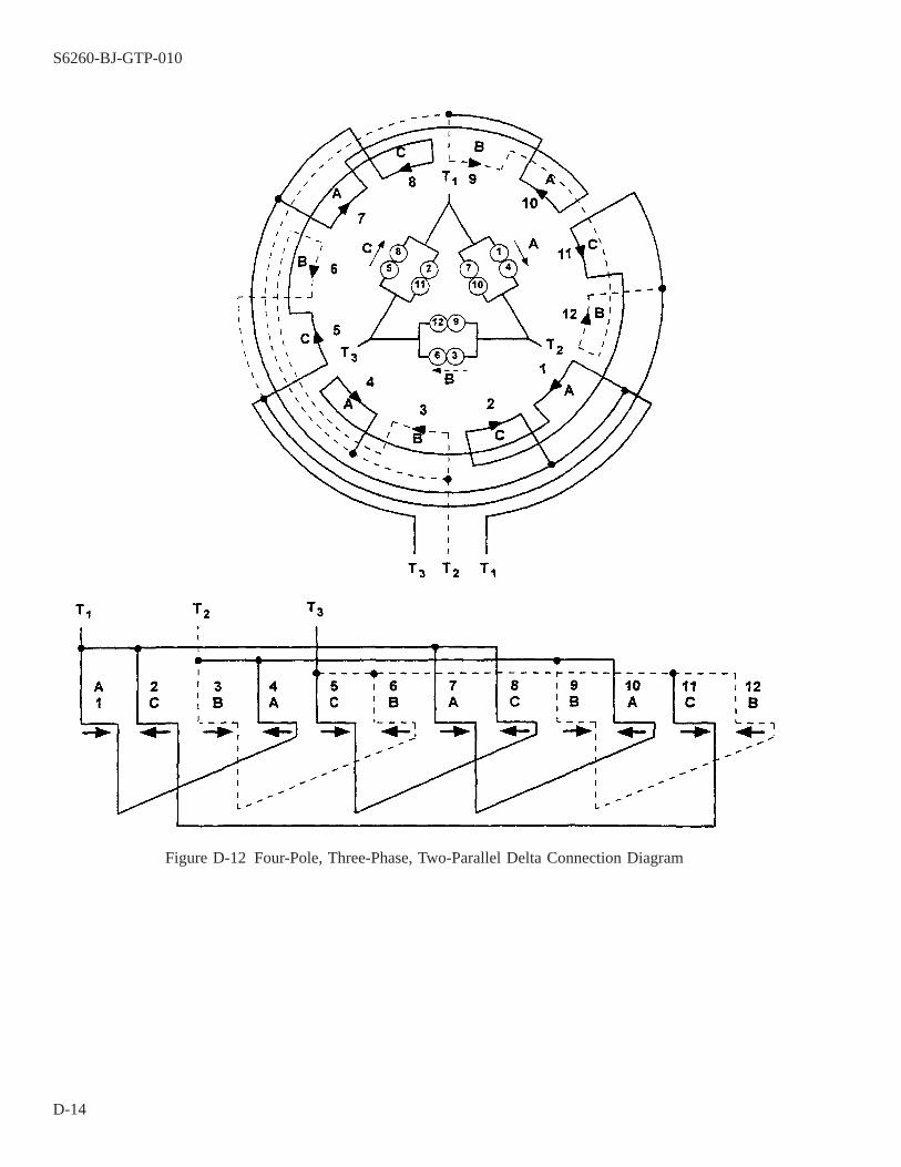
Figure D-12 Four-Pole, Three-Phase, Two-Parallel Delta Connection Diagram
S6260-BJ-GTP-010
D-14
APPENDIX E
PROCEDURE FOR DETERMINATION OF ELECTRIC MOTOR CONNECTIONS INENCAPSULATED MOTORS
NOTE
NAVSEA S9086-KC-STM-010/CH 300, Appendix B, indicates encapsulation isobsolete. Sealed Insulation System (SIS) replaces encapsulation and may only beperformed by a NAVSEA-certified facility (MIL-STD-2037). Afloat facilities arenot included in this program. The information provided here is provided for thosefew times when an existing encapsulated motor must be rewound as an interimmeasure.
E-1. SCOPE.
This procedure describes the method for determining the connection diagram of encapsulated motors prior toburnout Encapsulated motors may cause oven temperature runaway during burnout NAVSEA S9086-KC-STM-010/CH 300, on encapsulation of electric motors, suggests that the end turns of motors should be cut off on allmotors over 10 horsepower (hp) prior to burning out the windings. This presents problems since the connectiondiagram of the motor is not always available. The following procedure allows a connection diagram to be devel-oped and still limits the mass of epoxy put into the oven for burnout of the electric stator, thus preventing oventemperature runaway.
E-2. PROCEDURE.
E-3.
This procedure is based on the assumption that one lead is available and that failure has not occurred in whichall three leads have been completely burned out, so that the connection may be determined by measurement. Per-form the following steps to determine electric motor connection of an encapsulated motor:
a. Obtain the nameplate data from the motor.
b. Measure the length of the encapsulated winding.
c. Cut off the end turn at the connection end within 1/4 inch of the stator laminations by mounting the stator ona lathe and using a cutting speed of 150 revolutions per minute (r/m).
NOTE
The connection end is the end where the leads leave the encapsulating envelope.
d. Determine the coil throw by measuring with an ohmmeter on the stator end turn (not removed). Record thecoil throw.
e. Count the number of slots in the stator and record this number.
f. Count the number of coil sides in the slot and record the number.
S6260-BJ-GTP-010
E-1
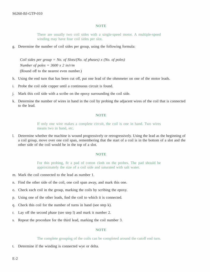
NOTE
There are usually two coil sides with a single-speed motor. A multiple-speedwinding may have four coil sides per slot.
g. Determine the number of coil sides per group, using the following formula:
Coil sides per group = No. of Slots/(No. of phases) x (No. of poles)
Number of poles = 3600 x 2 in/r/m
(Round off to the nearest even number.)
h. Using the end turn that has been cut off, put one lead of the ohmmeter on one of the motor leads.
i. Probe the coil side copper until a continuous circuit is found.
j. Mark this coil side with a scribe on the epoxy surrounding the coil side.
k. Determine the number of wires in hand in the coil by probing the adjacent wires of the coil that is connectedto the lead.
NOTE
If only one wire makes a complete circuit, the coil is one in hand. Two wiresmeans two in hand, etc.
l. Determine whether the machine is wound progressively or retrogressively. Using the lead as the beginning ofa coil group, move over one coil span, remembering that the start of a coil is in the bottom of a slot and theother side of the coil would be in the top of a slot.
NOTE
For this probing, fit a pad of cotton cloth on the probes. The pad should beapproximately the size of a coil side and saturated with salt water.
m. Mark the coil connected to the lead as number 1.
n. Find the other side of the coil, one coil span away, and mark this one.
o. Check each coil in the group, marking the coils by scribing the epoxy.
p. Using one of the other leads, find the coil to which it is connected.
q. Check this coil for the number of turns in hand (see step k).
r. Lay off the second phase (see step l) and mark it number 2.
s. Repeat the procedure for the third lead, marking the coil number 3.
NOTE
The complete grouping of the coils can be completed around the cutoff end turn.
t. Determine if the winding is connected wye or delta.
S6260-BJ-GTP-010
E-2

NOTE
If the winding is connected wye, there will be three coils common from each ofleads 1, 2, and 3. If the winding is connected delta, then there are two coils thatare common to leads 1, 2, and 3. If the winding is parallel wye, then six leadswill be common. A parallel delta will have four coils common to each of leads1, 2, and 3.
u. Cut off the other end turn one-fourth inch from the stator laminations.
v. Place the stator in the burnout oven. Burn it our at 600° F for the required length of time.
w. Remove the wires from the slots and determine the wire size and the number of conductors per coil side.
E-4. SUMMARY OF REWINDING DATA.
E-5.
The information necessary for rewinding the motor is now available. It may be summarized as follows:
E-5.1 Length of coil from step b, less one-half inch.
E-5.2 Coil span from step d.
E-5.3 Coils per group from step g.
E-5.4 Number of parallel conductors from step k.
E-5.5 Number of conductors from step w.
E-5.6 Conductor size or sizes from step w.
E-5.7 Connection, whether wye, delta, or parallel, from step t.
S6260-BJ-GTP-010
E-3 / (E-4 Blank)

E-4@@FIpgtype@@BLANK@@!FIpgtype@@

APPENDIX F
DESCRIPTIONS AND FEDERAL STOCK NUMBERS OF ELECTRICAL INSULATING MATERIALS
F-1. SCOPE.
This Appendix provides pertinent data, to include current Federal Stock Numbers (FSN) or Navy StockNumbers (NSN), for insulating materials carried in the Naval Supply System. It has been prepared to assist repairpersonnel in the selection of the correct electrical insulating materials for the maintenance and repair of electri-cal equipment.
F-2. AVAILABILITY OF MATERIALS.
Not every type, form, class, and size of insulating material is carried in the Naval Supply System. Materialsthat require purchase from commercial suppliers should be only those that conform to the latest edition of theapplicable military specification.
F-3. ROUND MAGNET WIRE.
Film-coated type round magnet wire shown on shipboard electrical equipment drawings may be listed as T2,B2, L2, H2, K2, M2, or with other numeric suffixes. The number indicates the insulation film thickness. A blank(no number) indicates single, 2 indicates heavy, 3 means triple, and 4 is quadruple. The letter symbols indicatethe temperature class: T=105° C, B=130° C, L=155° C, H=180° C, K=200° C, M=220° C. Fibrous coverings maybe shown as G2V, Dg, or Dg2. The G means a single glass serving, G2 means double glass, V means varnished,Dg means single Dacron-glass, and Dg2 means a double Dacron-glass serving. Round magnet wire per MilitarySpecification J-W-1177 must be utilized as shown in table F-1. Table F-2 shows magnet wire types.
NOTE
Use of respooled wire should be avoided if possible.
Table F-1 Identification of Types of Magnet Wire
Present Magnet Wire Types Recommended Rewind Magnet Wire Types
T, B, L, H, K, M MT2, B2, L2, H2, K2, M2 M2T3, B3, L3, H3, K3, M3 M3T4, B4, L4, H4, K4, M4 M3
BV, G2V, Dg, Dg2, TGV, T2GV, T2G2V, DGg, BDg2, BDgV, BDg2V, B2Dg, B2Dg2 For 155°C Ins. Sys.BGV, B2GV, BDg, B2Dg2, B2Dg2V, H2GX, H2G2X For 155°C Ins. Sys.
LDg, L2Dg2, HDg, H2Dg, LDgH, LDg2H, L2DgH, L2Eg2H For 155°C Ins. Sys.HDgG, H2DgG, MDgGM, M2DgGM M2DgGM For 155°C Ins. Sys.
Table F-2 Round Film Insulated Magnetic Wire (J-W-1177) 1 , 2
AWG Type 3 NSN 6145-00 Weight (lb.) Unit of Issue (U/I)
#7 M2 937-8587 250 Reel#8 M2 937-8585 200 Reel#9 M2 937-8583 250 Reel#10 M2 937-8410 250 Reel
S6260-BJ-GTP-010
F-1
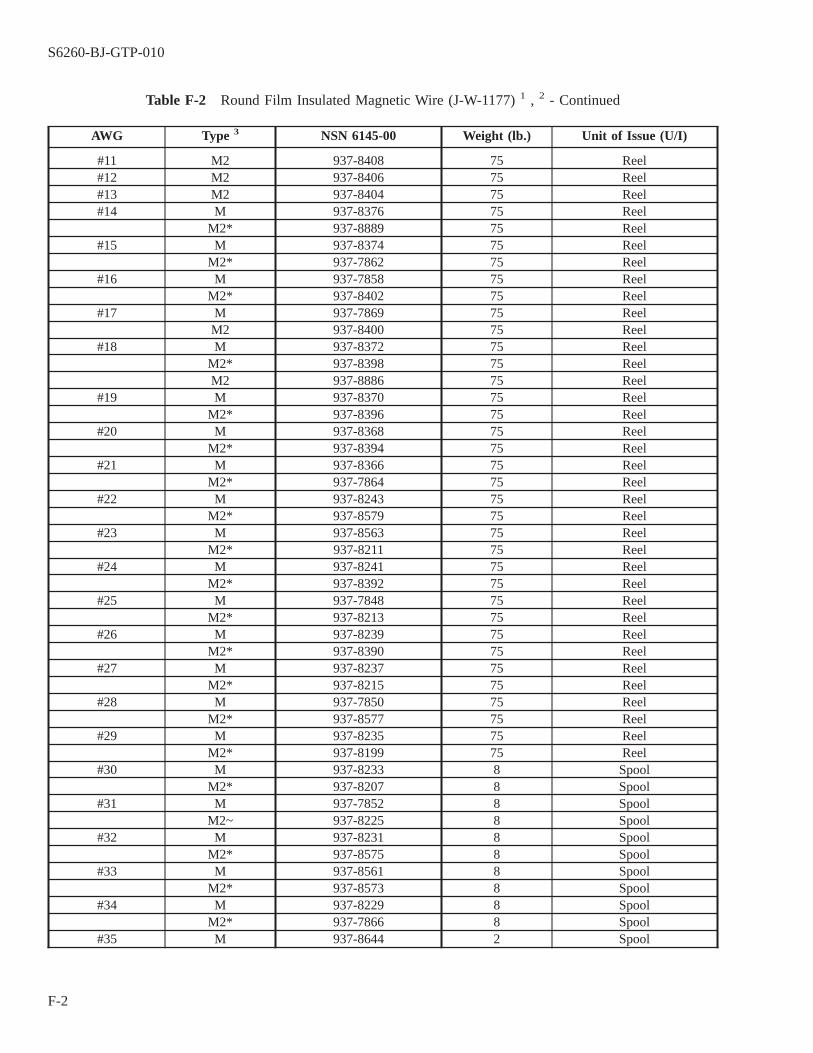
Table F-2 Round Film Insulated Magnetic Wire (J-W-1177) 1 , 2 - Continued
AWG Type 3 NSN 6145-00 Weight (lb.) Unit of Issue (U/I)
#11 M2 937-8408 75 Reel#12 M2 937-8406 75 Reel#13 M2 937-8404 75 Reel#14 M 937-8376 75 Reel
M2* 937-8889 75 Reel#15 M 937-8374 75 Reel
M2* 937-7862 75 Reel#16 M 937-7858 75 Reel
M2* 937-8402 75 Reel#17 M 937-7869 75 Reel
M2 937-8400 75 Reel#18 M 937-8372 75 Reel
M2* 937-8398 75 ReelM2 937-8886 75 Reel
#19 M 937-8370 75 ReelM2* 937-8396 75 Reel
#20 M 937-8368 75 ReelM2* 937-8394 75 Reel
#21 M 937-8366 75 ReelM2* 937-7864 75 Reel
#22 M 937-8243 75 ReelM2* 937-8579 75 Reel
#23 M 937-8563 75 ReelM2* 937-8211 75 Reel
#24 M 937-8241 75 ReelM2* 937-8392 75 Reel
#25 M 937-7848 75 ReelM2* 937-8213 75 Reel
#26 M 937-8239 75 ReelM2* 937-8390 75 Reel
#27 M 937-8237 75 ReelM2* 937-8215 75 Reel
#28 M 937-7850 75 ReelM2* 937-8577 75 Reel
#29 M 937-8235 75 ReelM2* 937-8199 75 Reel
#30 M 937-8233 8 SpoolM2* 937-8207 8 Spool
#31 M 937-7852 8 SpoolM2~ 937-8225 8 Spool
#32 M 937-8231 8 SpoolM2* 937-8575 8 Spool
#33 M 937-8561 8 SpoolM2* 937-8573 8 Spool
#34 M 937-8229 8 SpoolM2* 937-7866 8 Spool
#35 M 937-8644 2 Spool
S6260-BJ-GTP-010
F-2
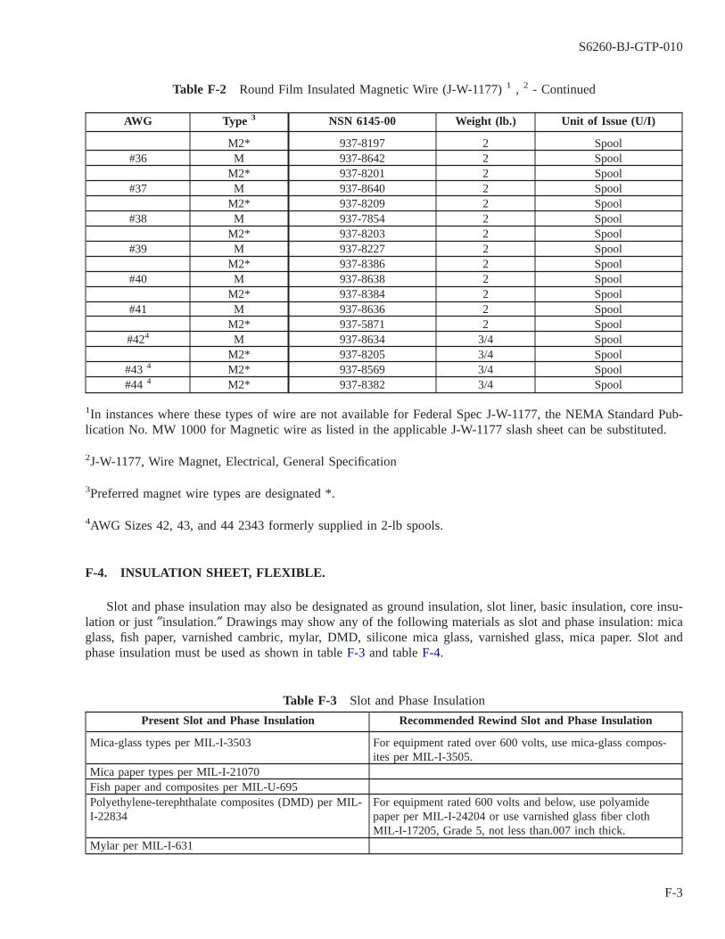
Table F-2 Round Film Insulated Magnetic Wire (J-W-1177) 1 , 2 - Continued
AWG Type 3 NSN 6145-00 Weight (lb.) Unit of Issue (U/I)
M2* 937-8197 2 Spool#36 M 937-8642 2 Spool
M2* 937-8201 2 Spool#37 M 937-8640 2 Spool
M2* 937-8209 2 Spool#38 M 937-7854 2 Spool
M2* 937-8203 2 Spool#39 M 937-8227 2 Spool
M2* 937-8386 2 Spool#40 M 937-8638 2 Spool
M2* 937-8384 2 Spool#41 M 937-8636 2 Spool
M2* 937-5871 2 Spool#424 M 937-8634 3/4 Spool
M2* 937-8205 3/4 Spool#43 4 M2* 937-8569 3/4 Spool#44 4 M2* 937-8382 3/4 Spool
1In instances where these types of wire are not available for Federal Spec J-W-1177, the NEMA Standard Pub-lication No. MW 1000 for Magnetic wire as listed in the applicable J-W-1177 slash sheet can be substituted.
2J-W-1177, Wire Magnet, Electrical, General Specification
3Preferred magnet wire types are designated *.
4AWG Sizes 42, 43, and 44 2343 formerly supplied in 2-lb spools.
F-4. INSULATION SHEET, FLEXIBLE.
Slot and phase insulation may also be designated as ground insulation, slot liner, basic insulation, core insu-lation or just ″insulation.″ Drawings may show any of the following materials as slot and phase insulation: micaglass, fish paper, varnished cambric, mylar, DMD, silicone mica glass, varnished glass, mica paper. Slot andphase insulation must be used as shown in table F-3 and table F-4.
Table F-3 Slot and Phase Insulation
Present Slot and Phase Insulation Recommended Rewind Slot and Phase Insulation
Mica-glass types per MIL-I-3503 For equipment rated over 600 volts, use mica-glass compos-ites per MIL-I-3505.
Mica paper types per MIL-I-21070Fish paper and composites per MIL-U-695Polyethylene-terephthalate composites (DMD) per MIL-I-22834
For equipment rated 600 volts and below, use polyamidepaper per MIL-I-24204 or use varnished glass fiber clothMIL-I-17205, Grade 5, not less than.007 inch thick.
Mylar per MIL-I-631
S6260-BJ-GTP-010
F-3
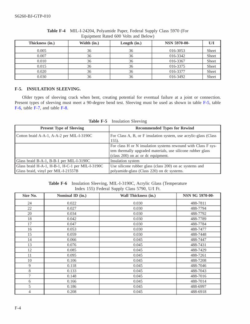
Table F-4 MIL-I-24204, Polyamide Paper, Federal Supply Class 5970 (ForEquipment Rated 600 Volts and Below)
Thickness (in.) Width (in.) Length (in.) NSN 5970-00- U/I
0.005 36 36 016-3053 Sheet0.007 36 36 016-3342 Sheet0.010 36 36 016-3367 Sheet0.015 36 36 016-3375 Sheet0.020 36 36 016-3377 Sheet0.030 36 36 016-3492 Sheet
F-5. INSULATION SLEEVING.
Older types of sleeving crack when bent, creating potential for eventual failure at a joint or connection.Present types of sleeving must meet a 90-degree bend test. Sleeving must be used as shown in table F-5, tableF-6, table F-7, and table F-8.
Table F-5 Insulation Sleeving
Present Type of Sleeving Recommended Types for Rewind
Cotton braid A-A-1, A-A-2 per MIL-I-3190C For Class A, B, or F insulation system, use acrylic-glass (Class155).For class H or N insulation systems rewound with Class F sys-tem thermally upgraded materials, use silicone rubber glass(class 200) on ac or dc equipment.
Glass braid B-A-1, B-B-1 per MIL-I-3190C Insulation systemGlass braid H-A-1, H-B-1, H-C-1 per MIL-I-3190CGlass braid, vinyl per MIL-I-21557B
Use silicone rubber glass (class 200) on ac systems andpolyamide-glass (Class 220) on dc systems.
Table F-6 Insulation Sleeving, MIL-I-3190C, Acrylic Glass (TemperatureIndex 155) Federal Supply Class 5790, U/I Ft.
Size No. Nominal ID (in.) Wall Thickness (in.) NSN 9G 5970-00-
24 0.022 0.030 488-781122 0.027 0.030 488-779420 0.034 0.030 488-779218 0.042 0.030 488-778917 0.047 0.030 488-778416 0.053 0.030 488-747715 0.059 0.030 488-744814 0.066 0.045 488-744713 0.076 0.045 488-743112 0.085 0.045 488-742911 0.095 0.045 488-726110 0.106 0.045 488-72089 0.118 0.045 488-70468 0.133 0.045 488-70437 0.148 0.045 488-70166 0.166 0.045 488-70145 0.186 0.045 488-69974 0.208 0.045 488-6918
S6260-BJ-GTP-010
F-4
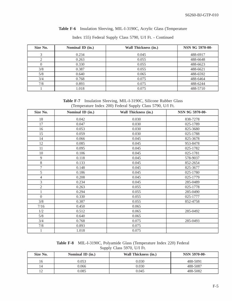
Table F-6 Insulation Sleeving, MIL-I-3190C, Acrylic Glass (Temperature
Index 155) Federal Supply Class 5790, U/I Ft. - Continued
Size No. Nominal ID (in.) Wall Thickness (in.) NSN 9G 5970-00-
3 0.234 0.045 488-69172 0.263 0.055 488-66480 0.330 0.055 488-6623
3/8 0.387 0.055 488-66215/8 0.640 0.065 488-65923/4 0.768 0.075 488-64647/8 0.893 0.075 488-62441 1.018 0.075 488-5710
Table F-7 Insulation Sleeving, MIL-I-3190C, Silicone Rubber Glass(Temperature Index 200) Federal Supply Class 5790, U/I Ft.
Size No. Nominal ID (in.) Wall Thickness (in.) NSN 9G 5970-00-
18 0.042 0.030 838-727817 0.047 0.030 025-178916 0.053 0.030 825-368015 0.059 0.030 025-178814 0.066 0.045 825-367812 0.085 0.045 953-847811 0.095 0.045 025-178210 0.106 0.045 025-17819 0.118 0.045 578-90378 0.133 0.045 852-26547 0.148 0.045 825-36775 0.186 0.045 025-17804 0.208 0.045 025-17793 0.234 0.045 285-04892 0.263 0.055 025-17781 0.294 0.055 285-04900 0.330 0.055 025-1777
3/8 0.387 0.055 852-47587/16 0.450 0.0651/2 0.512 0.065 285-04925/8 0.640 0.0653/4 0.768 0.075 285-04937/8 0.893 0.0751 1.018 0.075
Table F-8 MIL-I-3190C, Polyamide Glass (Temperature Index 220) FederalSupply Class 5970, U/I Ft.
Size No. Nominal ID (in.) Wall Thickness (in.) NSN 5970-00-
16 0.053 0.030 488-509114 0.066 0.030 488-508712 0.085 0.045 488-5082
S6260-BJ-GTP-010
F-5

Table F-8 MIL-I-3190C, Polyamide Glass (Temperature Index 220) Federal
Supply Class 5970, U/I Ft. - Continued
Size No. Nominal ID (in.) Wall Thickness (in.) NSN 5970-00-
10 0.106 0.045 488-49918 0.133 0.045 488-49426 0.166 0.045 488-48832 0.263 0.055 488-46600 0.330 0.055
F-6. INSULATION, LAMINATES, SHEETS.
Use table F-9 to determine the proper sheet insulation.
Table F-9 MIL-P-997, Glass Silicone Type GSG (Temperature Index 200)
Thickness (in.) NSN-5970-00- U/I
0.031 198-8327 lb.0.062 905-8772 lb.0.094 198-8325 lb.0.125 198-8324 lb.0.250 905-8774 lb.
F-7. LACING AND TYING TAPE.
Lacing and tying cords and tapes have been made from twisted cords, braided cords, and braided flat tapesusing cotton, flax, or glass yarns. Finishes applied to these materials to improve knot strength and applicationhave been waxes, synthetic rubbers, and resin coatings. Lacing and typing tape must be used as shown in tableF-10 and table F-11.
Table F-10 Identification of Types of Tape
Present Types Recommended Type
Glass cord per MIL-Y-1140 Polyamide, Type V, Finish A (natural) per MIL-T-43435ACotton cord per MIL-T-713 (also flax, hemp or resin)
Table F-11 MIL-T-43435A, Polyamide Tape - Heat Resistant, Flat Braids,Navy Supply Class 5970
NSN 5970-00- Size Width (in.) Thickness (in.) Breaking Strength (lb.) U/I Yds. per Spool
001-9356 1 0.225 0.014 85 500001-9357 2 0.125 0.012 50 500001-9358 3 0.090 0.012 35 500001-9359 4 0.062 0.08 25 500
F-8. INSULATION TAPE.
Utilize as shown in table F-12, table F-13, and table F-14.
S6260-BJ-GTP-010
F-6

Table F-12 MIL-Y-1140, Tape, Textile, Glass, Untreated, ECC-B, FederalSupply Class 8315
NSN 8315-00- Width (in.) Thickness (in.) Breaking Strength (lb.) U/I
290-8265 3/8 0.003 45 Roll290-8256 3/8 0.007 115 Roll290-8266 1/2 0.003 60 Roll290-8260 1/2 0.005 135 Roll290-8276 1/2 0.007 135 Roll290-8264 3/4 0.003 95 Roll290-8259 3/4 0.005 225 Roll290-8254 3/4 0.007 225 Roll290-8258 1 0.005 310 Roll290-8278 1 0.007 310 Roll
Table F-13 MIL-T-15126, Tape, Adhesive, Glass Backing Federal SupplyClass 5970 (Temperature Index 155)
NSN 5970-00- Width (in.) Thickness (in.) Diel. Str. (volts) U/I
543-1154 1/2 0.007 1000 Roll686-9151 1 0.007 Roll
Table F-14 MIL-T-19166, Tape, Adhesive, Glass Backing Federal SupplyClass 5970 (Temperature Index 200)
NSN 5970-00- Width (in.) Thickness (in.) Diel. Str. (Volts) U/I
709-0045 0.625 0.007 2000 Roll933-1406 0.250 0.007 200 Roll650-5345 0.500 0.012 4000 Roll
F-9. LEAD WIRE.
Use table F-15 to select the proper lead wire.
Table F-15 Lead Wire, MIL-W-16878
AWG Diameter (in.) NSN 6145-00-
Type EPDM (Ethylene-Propylene Diene Elastomer) Class 150° C, 600V18 0.142 01-212-477216 0.155 01-212-477314 0.170 01-212-477412 0.197 01-212-802810 0.252 01-212-16038 0.327 01-212-16046 0.383 01-270-85584 0.440 01-212-13412 0.494 01-212-4775
Type FF Silicone Rubber Glass Braid (Class 200) 1
22 0.100 284-148020 0.108 284-148118 0.118 284-1482
S6260-BJ-GTP-010
F-7

Table F-15 Lead Wire, MIL-W-16878 - Continued
AWG Diameter (in.) NSN 6145-00-
16 0.127 284-148314 0.176 284-148412 0.195 284-148S10 0.230 284-14868 0.327 284-14876 0.356 284-14884 0.412 284-14892 0.495 284-14901 0.552 284-14910 0.598 284-149200 0.651 284-1493
0000 0.775 284-1494Type EE Tetrafluoroethylene (Class 200)
24 0.0S4 01-995-160322 0.060 00-643-249420 0.068 00-811-223218 0.079 01-062-401116 0.089 00-089-656314 0.100 00-089-628912 0.124 01-089-656210 0.14S 01-957-19858 0.207 00-542-6677
1Silicone lead wire shall not be used in nonventilated brush-type machines.
F-10. INSULATION, SLOT WEDGES.
Use as shown in table F-16.
Table F-16 Formed Polyamide Paper (U Shape) Federal Supply Class 5970,U/I Ft.
Shape Width (in.) Thickness (in.) NSN 5970-00- FSCM (Mfr. Code) Mfr. Type
Curve 5/32 11/64 004-4491 87952 NHT 70-30Curve 7/32 3/16 004-4490 87952 NHT 86-30Curve 1/4 7/32 004-4489 87952 NHT 99-30Curve 5/16 1/4 004-4488 87952 NHT 117-30Curve 3/8 5/16 004-4487 87952 NHT 144-30Square 5/32 7/32 004-4486 87952 NHT 30-10-14Square 1/4 11/64 004-4492 87952 NHT 30-16-11Square 23/64 1/4 004-4493 87952 NHT 30-23-16
F-11. MISCELLANEOUS CONSUMABLE MATERIALS.
See table F-17 through table F-24 for details on various consumables.
S6260-BJ-GTP-010
F-8

Table F-17 Miscellaneous Consumable Materials
1. Slot Sticks-silicone glass 1/16″ thick MIL-P-15037 9Q-5970-00-905-8336
2. U-Shaped Wedges-NOMEXCurved 5.32 NHT-70-30 9Q-5970-00-004-4491Curved 7/32 NHT-86-30 9Q-5970-00-004-4490Curved 1/4 NHT-99-30 9Q-5970-00-004-4489Curved 5/16 NHT-117-30 9Q-5970-00-004-4488Curved 3/8 NHT-144-30 9Q-5970-00-004-4487Square 5/32 HHT-30-10-14 9Q-5970-00-004-4486Square 1/4 HHT-30-16-11 9Q-5970-00-004-4492Square 23-64 HHT-30-23-16 9Q-5970-00-004-4493
3. Flat Tape, Glass Braided Lacing Type V-Finish A MIL-T-43435A Natural (0.225)
9Q-5970-00-001-9356
4. Thermo Setting Tape, 1/2 inch MIL-T-15126 9Q-5970-00-543-11545. High Temperature Resistance Insulation Paper, Synthetic 24
inches x 36 inches, .007 Thickness NOMEX Type 40 orEquivalent MIL-I-24204
9Q-5970-00-016-3342
6. Temporary Slot Sticks Wood-Rag-NOMEX (use U-shapedwedges or scrap)Cotton Sail Twine
Table F-18 MIL-I-24092, Varnish, Clear, Baking, Solvent-Containing Types 1
Class NSN 5970-00- U/I Thinner
155 931-2413 1 gal can Xylene155 931-1170 5 gal can Xylene200 931-2414 5 gal can Xylene200 548-7211 1 gal can Xylene
1Xylene thinner is grade B per TT-X-916: NSN 6810-00-584-4070, 5 gal.
Table F-19 MIL-I-24092, Varnish, Clear, Air-Drying, Solvent-ContainingType 1
Grade NSN 5790-01- U/I Thinner Mfr. Brand No.
CA 190-5473 1 gal. can Mineral spirits AC 41 DolphCA 252-7481 1 gal. can Mineral spirits AC 43 Dolph
1Mineral spirits is grade I per TT-T-291: NSN 8010-00-558-7026, 5 gal.
Table F-20 MIL-I-24092, Varnish, Clear, Air-Drying Type
Type NSN 5970-01- U/I Mfr. Part No.
CA 078-5636 1 gal. Sterling U-122
S6260-BJ-GTP-010
F-9
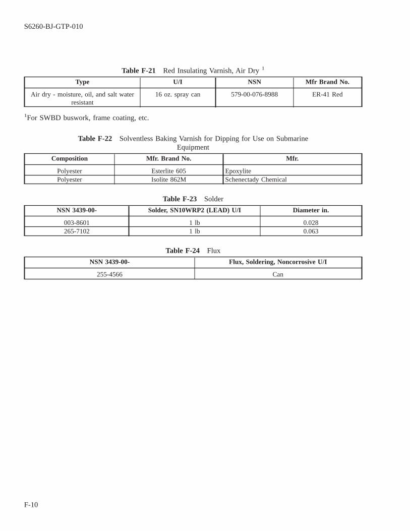
Table F-21 Red Insulating Varnish, Air Dry 1
Type U/I NSN Mfr Brand No.
Air dry - moisture, oil, and salt waterresistant
16 oz. spray can 579-00-076-8988 ER-41 Red
1For SWBD buswork, frame coating, etc.
Table F-22 Solventless Baking Varnish for Dipping for Use on SubmarineEquipment
Composition Mfr. Brand No. Mfr.
Polyester Esterlite 605 EpoxylitePolyester Isolite 862M Schenectady Chemical
Table F-23 Solder
NSN 3439-00- Solder, SN10WRP2 (LEAD) U/I Diameter in.
003-8601 1 lb 0.028265-7102 1 lb 0.063
Table F-24 Flux
NSN 3439-00- Flux, Soldering, Noncorrosive U/I
255-4566 Can
S6260-BJ-GTP-010
F-10
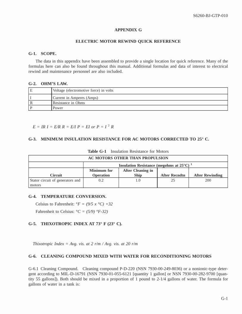
APPENDIX G
ELECTRIC MOTOR REWIND QUICK REFERENCE
G-1. SCOPE.
The data in this appendix have been assembled to provide a single location for quick reference. Many of theformulas here can also be found throughout this manual. Additional formulas and data of interest to electricalrewind and maintenance personnel are also included.
G-2. OHM’S LAW.
E Voltage (electromotive force) in volts
I Current in Amperes (Amps)R Resistance in OhmsP Power
E = IR I = E/R R = E/I P = EI or P = I 2 R
G-3. MINIMUM INSULATION RESISTANCE FOR AC MOTORS CORRECTED TO 25° C.
Table G-1 Insulation Resistance for Motors
AC MOTORS OTHER THAN PROPULSION
Insulation Resistance (megohms at 25°C) 1
CircuitMinimum for
OperationAfter Cleaning in
Ship After Recndtn After RewindingStator circuit of generators andmotors
0.2 1.0 25 200
G-4. TEMPERATURE CONVERSION.
Celsius to Fahrenheit: °F = (9/5 x °C) +32
Fahrenheit to Celsius: °C = (5/9) °F-32)
G-5. THIXOTROPIC INDEX AT 73° F (23° C).
Thixotropic Index = Avg. vis. at 2 r/m / Avg. vis. at 20 r/m
G-6. CLEANING COMPOUND MIXED WITH WATER FOR RECONDITIONING MOTORS
G-6.1 Cleaning Compound. Cleaning compound P-D-220 (NSN 7930-00-249-8036) or a nonionic-type deter-gent according to MIL-D-16791 (NSN 7930-01-055-6121 [quantity 1 gallon] or NSN 7930-00-282-9700 [quan-tity 55 gallons]). Both should be mixed in a proportion of 1 pound to 2-1/4 gallons of water. The formula forgallons of water in a tank is:
S6260-BJ-GTP-010
G-1
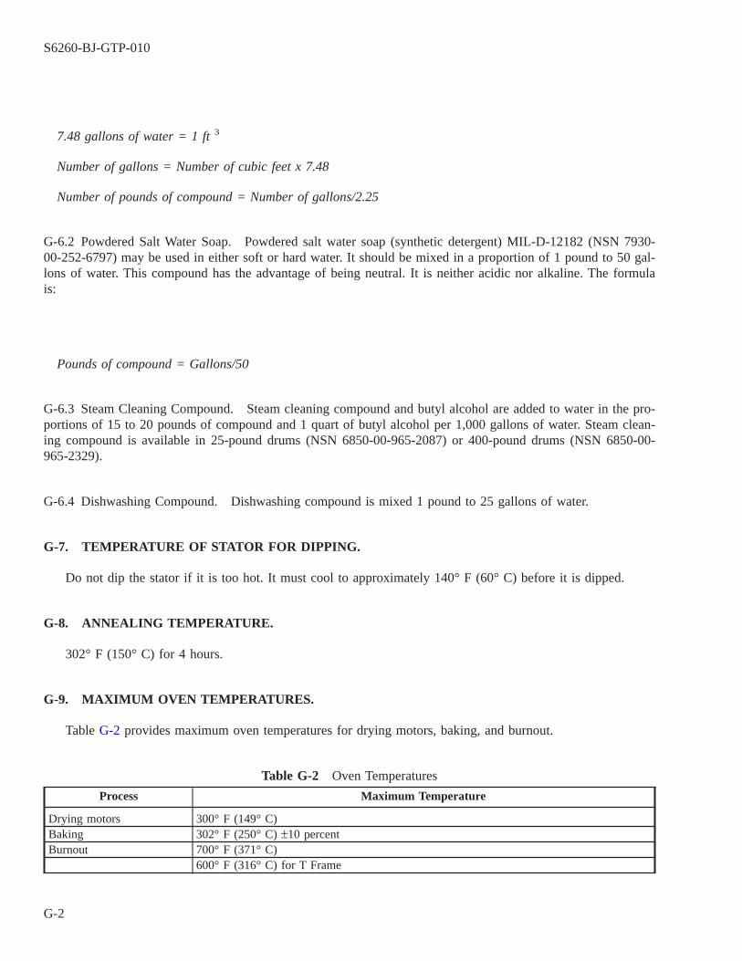
7.48 gallons of water = 1 ft 3
Number of gallons = Number of cubic feet x 7.48
Number of pounds of compound = Number of gallons/2.25
G-6.2 Powdered Salt Water Soap. Powdered salt water soap (synthetic detergent) MIL-D-12182 (NSN 7930-00-252-6797) may be used in either soft or hard water. It should be mixed in a proportion of 1 pound to 50 gal-lons of water. This compound has the advantage of being neutral. It is neither acidic nor alkaline. The formulais:
Pounds of compound = Gallons/50
G-6.3 Steam Cleaning Compound. Steam cleaning compound and butyl alcohol are added to water in the pro-portions of 15 to 20 pounds of compound and 1 quart of butyl alcohol per 1,000 gallons of water. Steam clean-ing compound is available in 25-pound drums (NSN 6850-00-965-2087) or 400-pound drums (NSN 6850-00-965-2329).
G-6.4 Dishwashing Compound. Dishwashing compound is mixed 1 pound to 25 gallons of water.
G-7. TEMPERATURE OF STATOR FOR DIPPING.
Do not dip the stator if it is too hot. It must cool to approximately 140° F (60° C) before it is dipped.
G-8. ANNEALING TEMPERATURE.
302° F (150° C) for 4 hours.
G-9. MAXIMUM OVEN TEMPERATURES.
Table G-2 provides maximum oven temperatures for drying motors, baking, and burnout.
Table G-2 Oven Temperatures
Process Maximum Temperature
Drying motors 300° F (149° C)Baking 302° F (250° C) ±10 percentBurnout 700° F (371° C)
600° F (316° C) for T Frame
S6260-BJ-GTP-010
G-2

G-10. MOTOR SPEED.
Table G-3 Motor Speed Table
Operating Speed Synchronous Speed Poles
3450 - 3575 3600 21725 - 1775 1800 41150 - 1175 1200 6825 - 875 900 8675 - 690 720 10500 - 575 600 12
G-11. NUMBER OF POLES.
120 x frequency/Speed
Motor speed may be obtained from the nameplate.
G-12. POLE PHASE GROUP (PPG).
Use the number of poles to determine the number of pole phase groups in the motor. The number of phasesfor which the motor is designed will be on the nameplate of the motor.
PPG = P x Ø, where
PPG = Pole phase groups
P = Number of poles determined using paragraph 8-9.1.
Ø = Phases for which the motor is designed.
G-13. COILS PER PPG (CPPG).
Individual coils are wound together or connected to form a pole phase group. To determine the number ofcoils in one pole phase group for a distributed winding (two coil sides per slot in a single winding):
Coils per group = Total active coils/(Number of phases) x (Number of poles)
An active coil is a coil that is electrically connected in the stator circuit (Total active coils = Active coils perphase x Number of phases).
G-14. COILS PER GROUP (CPG).
Coils per group = Stator slots/Pole Phase Groups
S6260-BJ-GTP-010
G-3
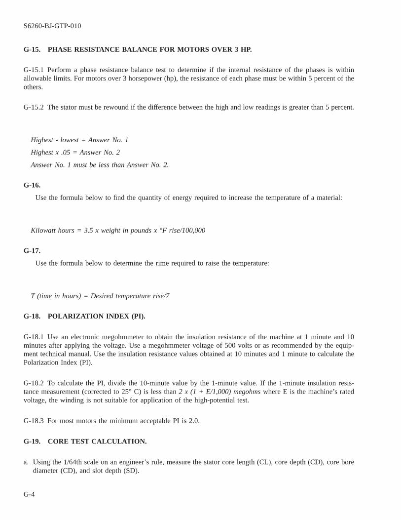
G-15. PHASE RESISTANCE BALANCE FOR MOTORS OVER 3 HP.
G-15.1 Perform a phase resistance balance test to determine if the internal resistance of the phases is withinallowable limits. For motors over 3 horsepower (hp), the resistance of each phase must be within 5 percent of theothers.
G-15.2 The stator must be rewound if the difference between the high and low readings is greater than 5 percent.
Highest - lowest = Answer No. 1
Highest x .05 = Answer No. 2
Answer No. 1 must be less than Answer No. 2.
G-16.
Use the formula below to find the quantity of energy required to increase the temperature of a material:
Kilowatt hours = 3.5 x weight in pounds x °F rise/100,000
G-17.
Use the formula below to determine the rime required to raise the temperature:
T (time in hours) = Desired temperature rise/7
G-18. POLARIZATION INDEX (PI).
G-18.1 Use an electronic megohmmeter to obtain the insulation resistance of the machine at 1 minute and 10minutes after applying the voltage. Use a megohmmeter voltage of 500 volts or as recommended by the equip-ment technical manual. Use the insulation resistance values obtained at 10 minutes and 1 minute to calculate thePolarization Index (PI).
G-18.2 To calculate the PI, divide the 10-minute value by the 1-minute value. If the 1-minute insulation resis-tance measurement (corrected to 25° C) is less than 2 x (1 + E/1,000) megohms where E is the machine’s ratedvoltage, the winding is not suitable for application of the high-potential test.
G-18.3 For most motors the minimum acceptable PI is 2.0.
G-19. CORE TEST CALCULATION.
a. Using the 1/64th scale on an engineer’s rule, measure the stator core length (CL), core depth (CD), core borediameter (CD), and slot depth (SD).
S6260-BJ-GTP-010
G-4
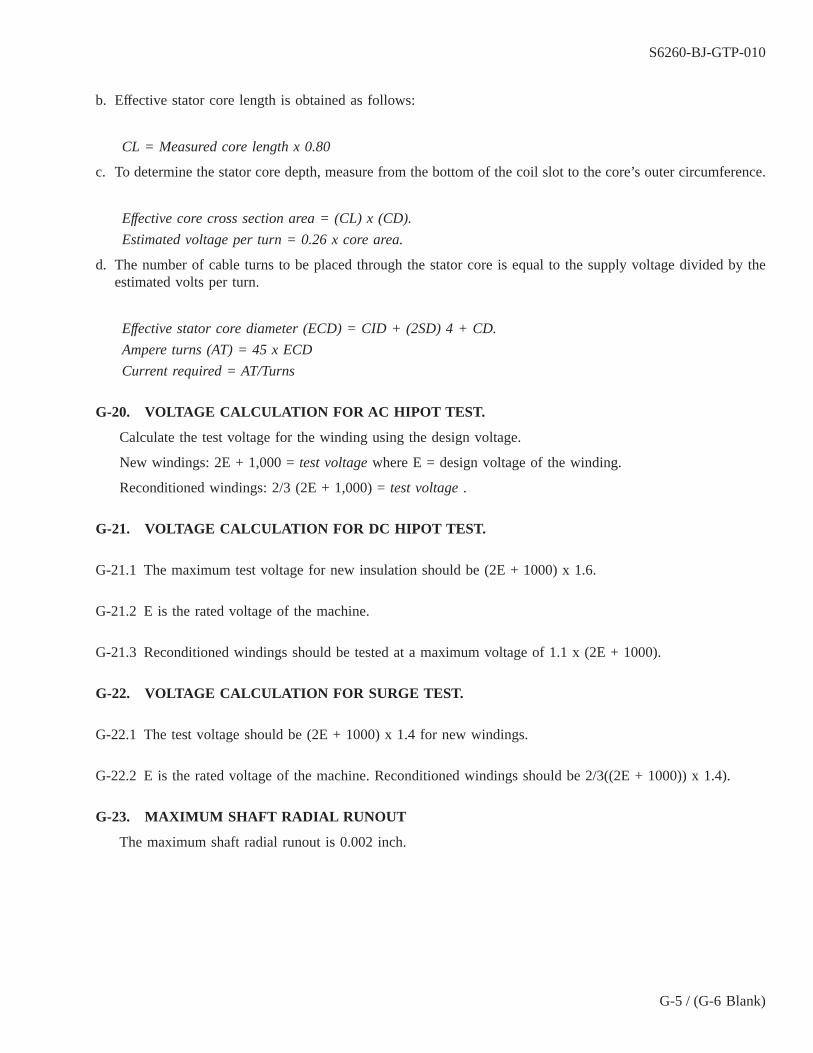
b. Effective stator core length is obtained as follows:
CL = Measured core length x 0.80
c. To determine the stator core depth, measure from the bottom of the coil slot to the core’s outer circumference.
Effective core cross section area = (CL) x (CD).
Estimated voltage per turn = 0.26 x core area.
d. The number of cable turns to be placed through the stator core is equal to the supply voltage divided by theestimated volts per turn.
Effective stator core diameter (ECD) = CID + (2SD) 4 + CD.
Ampere turns (AT) = 45 x ECD
Current required = AT/Turns
G-20. VOLTAGE CALCULATION FOR AC HIPOT TEST.
Calculate the test voltage for the winding using the design voltage.
New windings: 2E + 1,000 = test voltage where E = design voltage of the winding.
Reconditioned windings: 2/3 (2E + 1,000) = test voltage .
G-21. VOLTAGE CALCULATION FOR DC HIPOT TEST.
G-21.1 The maximum test voltage for new insulation should be (2E + 1000) x 1.6.
G-21.2 E is the rated voltage of the machine.
G-21.3 Reconditioned windings should be tested at a maximum voltage of 1.1 x (2E + 1000).
G-22. VOLTAGE CALCULATION FOR SURGE TEST.
G-22.1 The test voltage should be (2E + 1000) x 1.4 for new windings.
G-22.2 E is the rated voltage of the machine. Reconditioned windings should be 2/3((2E + 1000)) x 1.4).
G-23. MAXIMUM SHAFT RADIAL RUNOUT
The maximum shaft radial runout is 0.002 inch.
S6260-BJ-GTP-010
G-5 / (G-6 Blank)

G-6@@FIpgtype@@BLANK@@!FIpgtype@@
REAR SECTION
TECHNICAL MANUAL DEFICIENCY/EVALUATION REPORT (TMDER)
NOTE
Ships, training activities, supply points, depots, Naval Shipyards, and Supervi-sors of Shipbuilding are requested to arrange for the maximum practical use andevaluation of NAVSEA technical manuals. All errors, omissions, discrepancies,and suggestions for improvement to NAVSEA technical manuals shall be for-warded to:Commander,CODE 310 TMDER, BLDG 1388NAVSURFWARCENDIV NSDSA4363 MISSLE WAYPORT HUENEME CA 93043-4307on NAVSEA/SPAWAR Technical Manual Deficiency/Evaluation Report(TMDER), NAVSEA Form 4160/1. To facilitate such reporting, print, complete,and mail NAVSEA form 4160/1 below or submit TMDERS at web site:
https://nsdsa2.phdnswc.navy.mil/tmder/tmder-generate.asp?lvl=1
All feedback comments shall be thoroughly investigated and originators will beadvised of action resulting therefrom. Copies of NAVSEA Form 4160/1 may berequisitioned from the Naval Systems Data Support Activity Code 310 at theabove address.
TMDER / MAILER
S6260-BJ-GTP-010
Rear-1 / (Rear-2 Blank)

Rear-2@@FIpgtype@@BLANK@@!FIpgtype@@

Ref: NAVSEAINST 4160.3A NAVSEA S0005-AA-GYD-030/TMMP
NAVSEA/SPAWAR TECHNICAL MANUAL DEFICIENCY/EVALUATION REPORT (TMDER) INSTRUCTIONS: Continue on 8 ½” x 11” page if additional space is needed. 1. Use this report to indicate deficiencies, problems and recommendations relating to publications. 2. For CLASSIFIED TMDERs see OPNAVINST 5510H for mailing requirements. 3. For TMDERs that affect more than one publication, submit a separate TMDER for each. 4. Submit TMDERs at web site https://nsdsa2.phdnswc.navy.mil or mail to: COMMANDER, CODE 310 TMDER BLDG 1389,NAVSURFWARCENDIV NSDSA, 4363 MISSILE WAY, PORT HUENEME CA 93043-4307
1. PUBLICATION NUMBER 2. VOL/PART 3. REV/DATE OR CHG/DATE 4. SYSTEM/EQUIPMENT ID
5. TITLE OF PUBLICATION 6. REPORT CONTROL NUMBER (6 digit UIC-YY-any four: xxxxxx-03-xxxx)
7. RECOMMEND CHANGES TO PUBLICATION
7a. Page # 7b. Para # 7c. RECOMMENDED CHANGES AND REASONS
8. ORIGINATOR’S NAME AND WORK CENTER 9. DATE 10. ORIGINATOR’S E-MAIL ADDRESS 11. TMMA of Manual (NSDSA will complete)
12. SHIP OR ACTIVITY Name and Address (Include UIC/CAGE/HULL) 13. Phone Numbers: Commercial ( ) -
DSN - FAX ( ) -
NAVSEA 4160/1 (Rev. 7-2003) S/N 0116-lf-985-4100

FOLD HERE AND TAPE SECURELY PLEASE DO NOT STAPLE
INCLUDE COMPLETE ADDRESS USE PROPER POSTAGE
FOR OFFICE USE ONLY
COMMANDER CODE 310 BLDG 1389 NAVSURFWARCENDIV NSDSA
4363 MISSILE WAY PORT HUENEME, CA 93043-4307
FOLD HERE AND TAPE SECURELY PLEASE DO NOT STAPLE