ELECTRICAL MACHINERY LAB (436) - madinpoly.commadinpoly.com/pdf/labmanual/3/ELECTRICAL MACHINERY LAB...
37
ELECTRICAL MACHINERY LAB (436) DEPARTMENT OF ELECTRICAL & ELECTRONICS ENGINEERING
-
Upload
duongtuyen -
Category
Documents
-
view
242 -
download
1
Transcript of ELECTRICAL MACHINERY LAB (436) - madinpoly.commadinpoly.com/pdf/labmanual/3/ELECTRICAL MACHINERY LAB...
ELECTRICAL MACHINERY
LAB (436)
DEPARTMENT OF ELECTRICAL & ELECTRONICS
ENGINEERING
TOPICS PAGE NO.
LOAD TEST ON SINGLE PHASE TRANSFORMER. 01
SC AND OC OF SINGLEPHASE TRANSFORMER. 03
LOAD TEST ON DC SERIES MOTOR 10
LOAD TEST ON DC SHUNT MOTOR. 13
OCC OF SELF EXCITED DC GENERATOR 16
SWINBERN’S TEST 19
LOAD TEST ON DC SHUNT GENERATOR 22
OCC OF SEPERATELY EXCITED DC SHUNT
GENERATOR 27
POLARITY AND TURNS RATIO TEST 30
BANKING OF TRANSFORMERS 35
ELECTRICAL MACHINERYLAB DEPARTMENT OF EEE
MA’DIN Polytechnic college 1
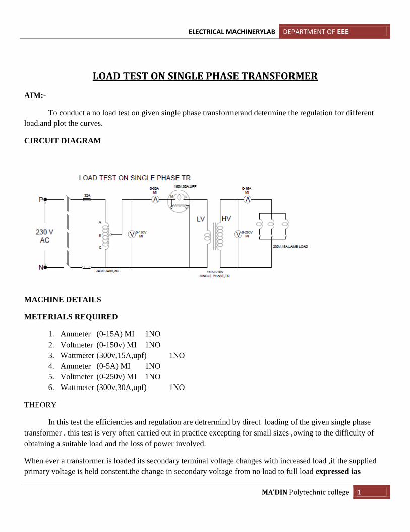
LOAD TEST ON SINGLE PHASE TRANSFORMER
AIM:-
To conduct a no load test on given single phase transformerand determine the regulation for different
load.and plot the curves.
CIRCUIT DIAGRAM
MACHINE DETAILS
METERIALS REQUIRED
1. Ammeter (0-15A) MI 1NO
2. Voltmeter (0-150v) MI 1NO
3. Wattmeter (300v,15A,upf) 1NO
4. Ammeter (0-5A) MI 1NO
5. Voltmeter (0-250v) MI 1NO
6. Wattmeter (300v,30A,upf) 1NO
THEORY
In this test the efficiencies and regulation are detrermind by direct loading of the given single phase
transformer . this test is very often carried out in practice excepting for small sizes ,owing to the difficulty of
obtaining a suitable load and the loss of power involved.
When ever a transformer is loaded its secondary terminal voltage changes with increased load ,if the supplied
primary voltage is held constent.the change in secondary voltage from no load to full load expressed ias
ELECTRICAL MACHINERYLAB DEPARTMENT OF EEE
MA’DIN Polytechnic college 2
percentage of no load voltage is known a voltage is known as voltage regulatin of a transformer (ie, secondary
voltage at noload –secondary voltage at full load) 𝐸2−𝑉2
𝐸2 (the secondary rated voltage of a transformer is equal to
the secondary voltage at no load,ie,E2
The efficienciy of a transformer is defaind as the ratio of output power to input power,thus efficeiency=output
power/input power
In this experiment input power is measured directly from the wattmeter connected in the primary side and
output power is obtained by multiplying the volt meter reading and ammeter reading in the secondary side.
PROCEDURE:-
1. Connect the circuit diagram as per the circuit diagram
2. Adjust the autotransformer till the voltmeter reads rated voltage.
3. Note the no load readings and enter them as first set of readings in tabular column.
4. Load the transformer gradually and take all meter readings each time till the secondary current reaches
rated value.
5. Tabulate the readings. And finish the work
TABULATION
Sl No I1 in
Amps
V1 in
volts
W in
watts
I2 in
Amps
V2 in
volts
Input
in
watts
Output=V2xI2 %efficiency %
Regulation
CALCULATION
Output=V2xI2.
Input= W
%efficiency=𝑂/𝑝
𝑖/𝑝 x100.
Regulation= 𝑜𝑉2−𝑉2
𝑜𝑉2 x100.
RESULT
.
ELECTRICAL MACHINERYLAB DEPARTMENT OF EEE
MA’DIN Polytechnic college 3
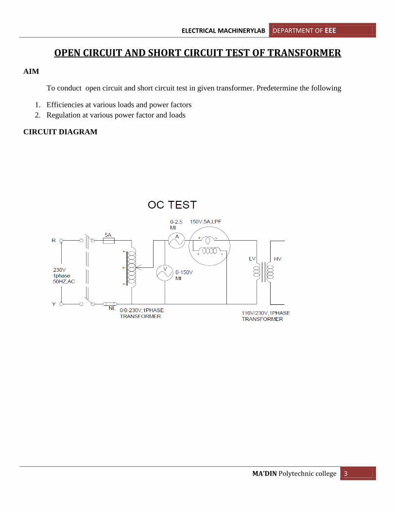
OPEN CIRCUIT AND SHORT CIRCUIT TEST OF TRANSFORMER
AIM
To conduct open circuit and short circuit test in given transformer. Predetermine the following
1. Efficiencies at various loads and power factors
2. Regulation at various power factor and loads
CIRCUIT DIAGRAM
ELECTRICAL MACHINERYLAB DEPARTMENT OF EEE
MA’DIN Polytechnic college 4
MACHINE DETAILS
METERIALS REQUIRED
1. Ammeter (0-2.5A) MI 1NO
2. Ammeter (0-15A)MI 1NO
3. Volt meter (0-250v) 1no
4. Voltmeter (0-50v) MI 1NO
5. Wattmeter (150V,5A,LPF) 1NO
6. Wattmeter (150V,15A,UPF) 1NO
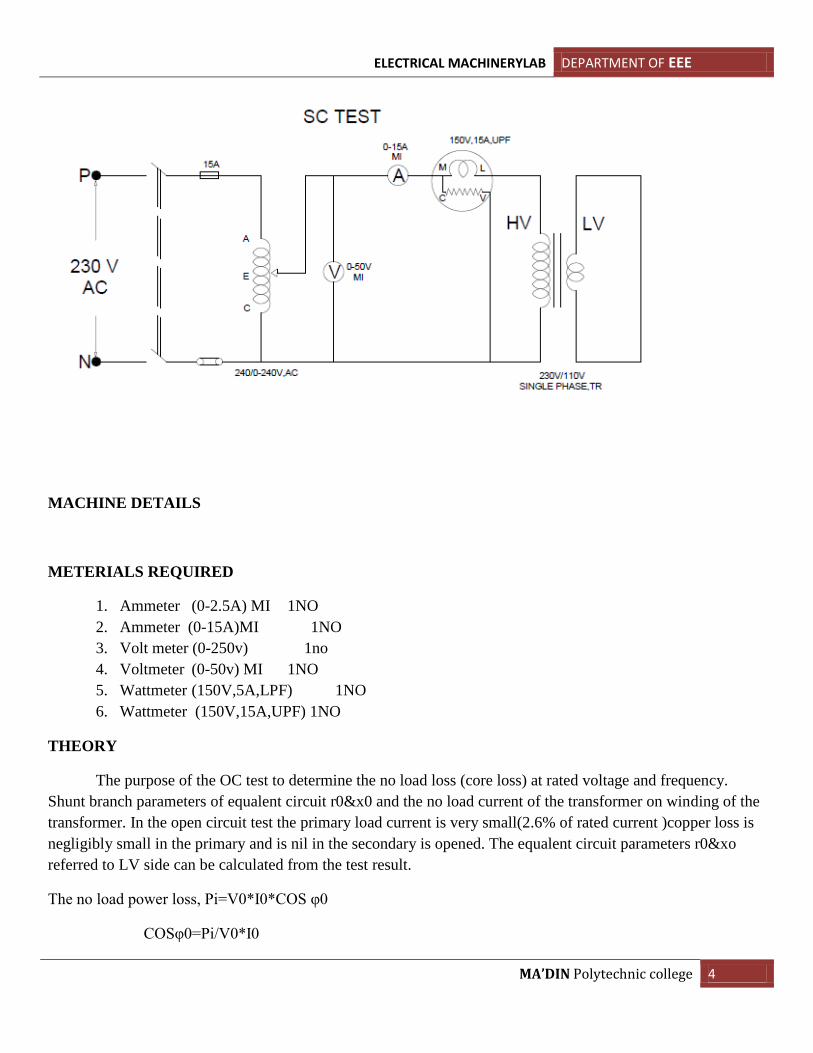
THEORY
The purpose of the OC test to determine the no load loss (core loss) at rated voltage and frequency.
Shunt branch parameters of equalent circuit r0&x0 and the no load current of the transformer on winding of the
transformer. In the open circuit test the primary load current is very small(2.6% of rated current )copper loss is
negligibly small in the primary and is nil in the secondary is opened. The equalent circuit parameters r0&xo
referred to LV side can be calculated from the test result.
The no load power loss, Pi=V0*I0*COS φ0
COSφ0=Pi/V0*I0
ELECTRICAL MACHINERYLAB DEPARTMENT OF EEE
MA’DIN Polytechnic college 5
Magnetising component of I0 =Im=I0SIN φ0
Energy component of I0=Ie=I0COS φ0
The noload resistance R0=V0/Ie and the no load reactance X0= V0/Im
These values can be transferred to hv side as R0’=R0(V2/V1)
2 and X0
’=X0(V2/V1)
2
SC Test is to conduct for determining the full load copper loss and the equalent resistance and resistance of the
transformer as refferd to the metering side. In this test one winding usually LV side is solidly short circuited and
a low voltage (2-12% of primary voltage ) is applied to the HV side such that rated current flows through the
winding since applied voltage is very low ,iron losses are very small and may be neglected. Hence the
wattmeter shows the full load copper loss Pcu for the bwhole transformer. If VSC is the voltage required to
circulate the rated current I2(KVA X 1000/V1) Then the equavalent circuit parameters can be found as
Z02=VSC/I2 and R02=PCu
Then X02= 𝑍022 + 𝑅02 These parameters can be transferred to the LV side as
R2’=R2(V2/V1)
2 and X2
’=X2(V2/V1)
2 secondary side R02 and X02 the regulation at any PF and loading factor(x)
can be predetermind as regulation= XI2(R02 COS φ0+- X02 SIN φ0)/V2 Where (+) for lagging and(-) for leading
power factors) from the full load copper loss and iron loss the efficiency at any loading factor and pf can be pre
determind as
Efficiency= 𝑋1000𝐾𝑉𝐴𝑋 .𝑃𝐹
𝑋1000𝐾𝑉𝐴𝑋𝑃𝐹+𝑋2𝑃𝑐𝑢+𝑃𝑖
PROCEDURE
OC TEST
1. Make connection as per the circuit diagram
2. Keep the autotransformer in minimum position
3. Adjust the auto transformer upto rated voltage of the transformer
4. Take the meter readings and tabulate the readings
5. Finish the work
SC TEST
1. Make connection as per the circuit diagram
2. Keep the autotransformer in minimum position
3. Adjust the auto transformer upto rated current of the transformer
4. Take the meter readings and tabulate the readings
5. Finish the work
.
ELECTRICAL MACHINERYLAB DEPARTMENT OF EEE
MA’DIN Polytechnic college 6
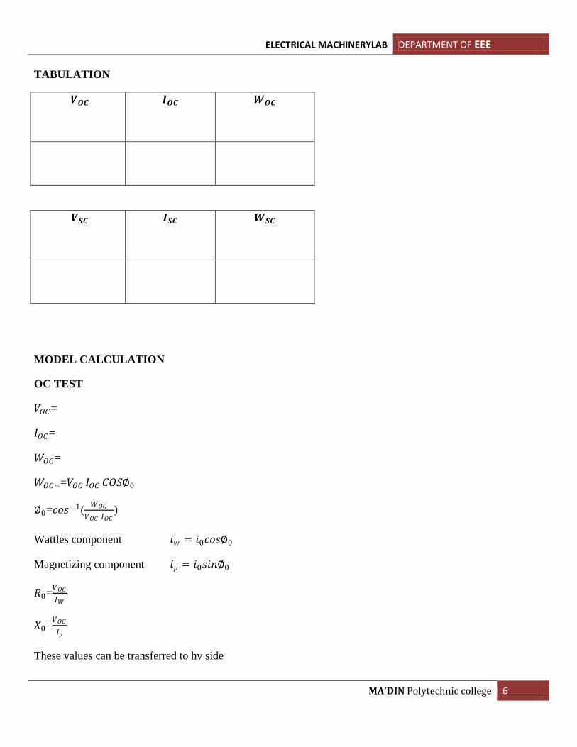
TABULATION
𝑽𝑶𝑪
𝑰𝑶𝑪
𝑾𝑶𝑪
𝑽𝑺𝑪
𝑰𝑺𝑪
𝑾𝑺𝑪
MODEL CALCULATION
OC TEST
𝑉𝑂𝐶=
𝐼𝑂𝐶=
𝑊𝑂𝐶=
𝑊𝑂𝐶==𝑉𝑂𝐶 𝐼𝑂𝐶 𝐶𝑂𝑆∅0
∅0=𝑐𝑜𝑠−1(𝑊𝑂𝐶
𝑉𝑂𝐶 𝐼𝑂𝐶)
Wattles component 𝑖𝑤 = 𝑖0𝑐𝑜𝑠∅0
Magnetizing component 𝑖µ = 𝑖0𝑠𝑖𝑛∅0
𝑅0=𝑉𝑂𝐶
𝐼𝑊
𝑋0=𝑉𝑂𝐶
𝐼µ
These values can be transferred to hv side
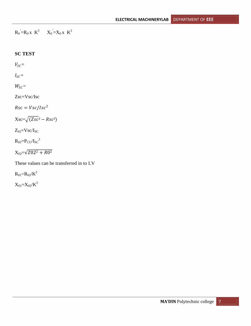
ELECTRICAL MACHINERYLAB DEPARTMENT OF EEE
MA’DIN Polytechnic college 7
R0’=R0 x K
2 X0
’=X0 x K
2
SC TEST
𝑉𝑆𝐶=
𝐼𝑆𝐶=
𝑊𝑆𝐶=
Zsc=Vsc/Isc
𝑅𝑠𝑐 = 𝑉𝑠𝑐/𝐼𝑠𝑐2
Xsc= (𝑍𝑠𝑐²− 𝑅𝑠𝑐²)
Z02=Vsc/ISC
R02=PCU/ISC2
X02= 𝑍022 + 𝑅02
These values can be transferred in to LV
R01=R02/K2
X01=X02/K2
ELECTRICAL MACHINERYLAB DEPARTMENT OF EEE
MA’DIN Polytechnic college 8
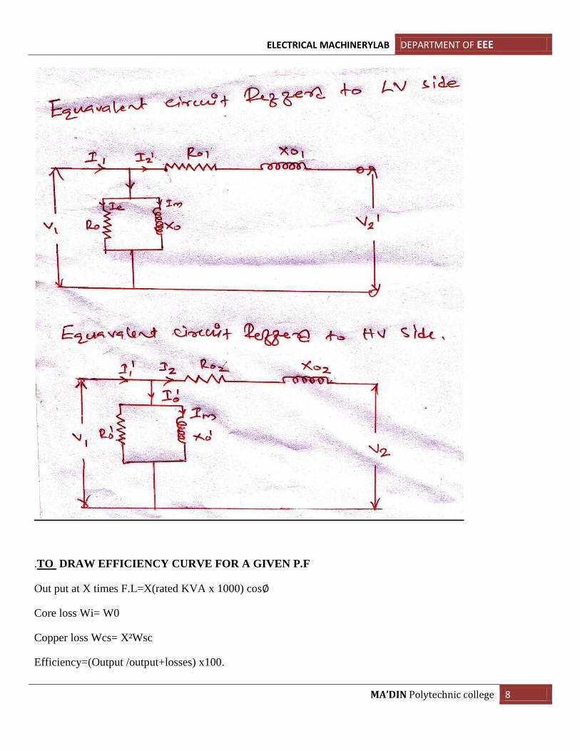
.TO DRAW EFFICIENCY CURVE FOR A GIVEN P.F
Out put at X times F.L=X(rated KVA x 1000) cos∅
Core loss Wi= W0
Copper loss Wcs= X²Wsc
Efficiency=(Output /output+losses) x100.
ELECTRICAL MACHINERYLAB DEPARTMENT OF EEE
MA’DIN Polytechnic college 9
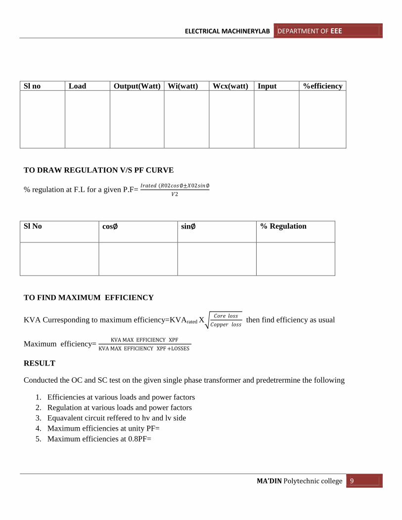
Sl no Load Output(Watt) Wi(watt) Wcx(watt) Input %efficiency
TO DRAW REGULATION V/S PF CURVE
% regulation at F.L for a given P.F= 𝐼𝑟𝑎𝑡𝑒𝑑 (𝑅02𝑐𝑜𝑠∅±𝑋02𝑠𝑖𝑛∅
𝑉2
Sl No cos∅ sin∅ % Regulation
TO FIND MAXIMUM EFFICIENCY
KVA Curresponding to maximum efficiency=KVArated X 𝐶𝑜𝑟𝑒 𝑙𝑜𝑠𝑠
𝐶𝑜𝑝𝑝𝑒𝑟 𝑙𝑜𝑠𝑠 then find efficiency as usual
Maximum efficiency= KVA MAX EFFICIENCY XPF
KVA MAX EFFICIENCY XPF +LOSSES
RESULT
Conducted the OC and SC test on the given single phase transformer and predetrermine the following
1. Efficiencies at various loads and power factors
2. Regulation at various loads and power factors
3. Equavalent circuit reffered to hv and lv side
4. Maximum efficiencies at unity PF=
5. Maximum efficiencies at 0.8PF=
ELECTRICAL MACHINERYLAB DEPARTMENT OF EEE
MA’DIN Polytechnic college 10
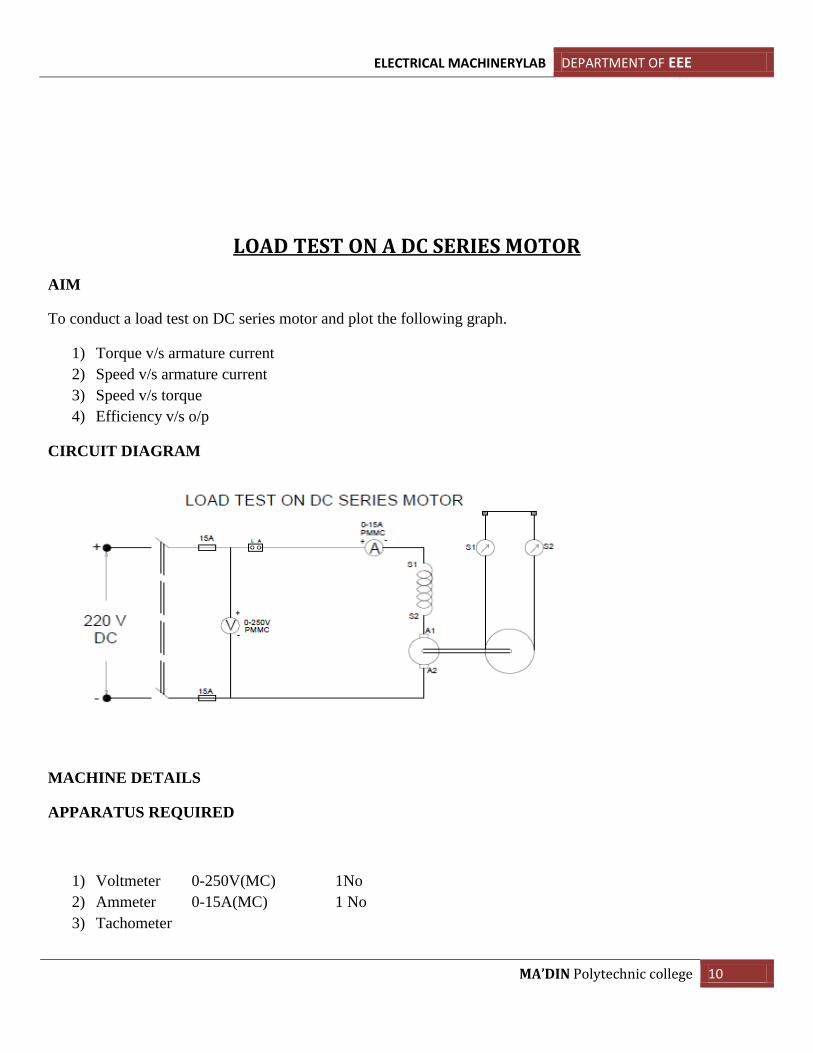
LOAD TEST ON A DC SERIES MOTOR
AIM
To conduct a load test on DC series motor and plot the following graph.
1) Torque v/s armature current
2) Speed v/s armature current
3) Speed v/s torque
4) Efficiency v/s o/p
CIRCUIT DIAGRAM
MACHINE DETAILS
APPARATUS REQUIRED
1) Voltmeter 0-250V(MC) 1No
2) Ammeter 0-15A(MC) 1 No
3) Tachometer
ELECTRICAL MACHINERYLAB DEPARTMENT OF EEE
MA’DIN Polytechnic college 11
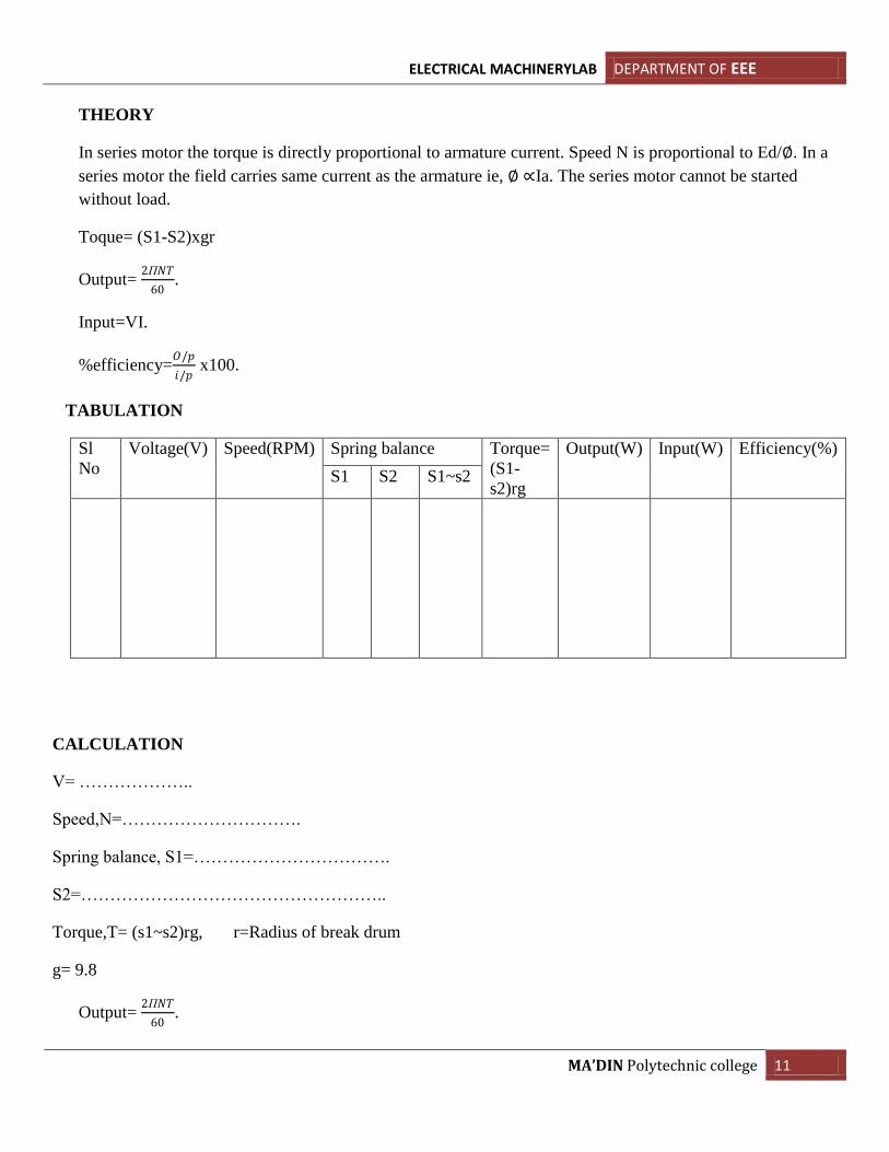
THEORY
In series motor the torque is directly proportional to armature current. Speed N is proportional to Ed/∅. In a
series motor the field carries same current as the armature ie, ∅ ∝Ia. The series motor cannot be started
without load.
Toque= (S1-S2)xgr
Output= 2П𝑁𝑇
60.
Input=VI.
%efficiency=𝑂/𝑝
𝑖/𝑝 x100.
TABULATION
Sl
No
Voltage(V) Speed(RPM) Spring balance Torque=
(S1-
s2)rg
Output(W) Input(W) Efficiency(%)
S1 S2 S1~s2
CALCULATION
V= ………………..
Speed,N=………………………….
Spring balance, S1=…………………………….
S2=……………………………………………..
Torque,T= (s1~s2)rg, r=Radius of break drum
g= 9.8
Output= 2П𝑁𝑇
60.

ELECTRICAL MACHINERYLAB DEPARTMENT OF EEE
MA’DIN Polytechnic college 12
%efficiency=𝑂/𝑝
𝑖/𝑝 x100.
PROCEDURE
1) Connections are made as per diagram.
2) Apply a small load to the motor and start the motor.
3) Note the meter readings
4) Vary the spring balance at different load.
5) Note the corresponding readings.
6) Tabulate the reading and plot the graph.
RESULT
The load test on series motor is conducted and plotted the graphs.
ELECTRICAL MACHINERYLAB DEPARTMENT OF EEE
MA’DIN Polytechnic college 13
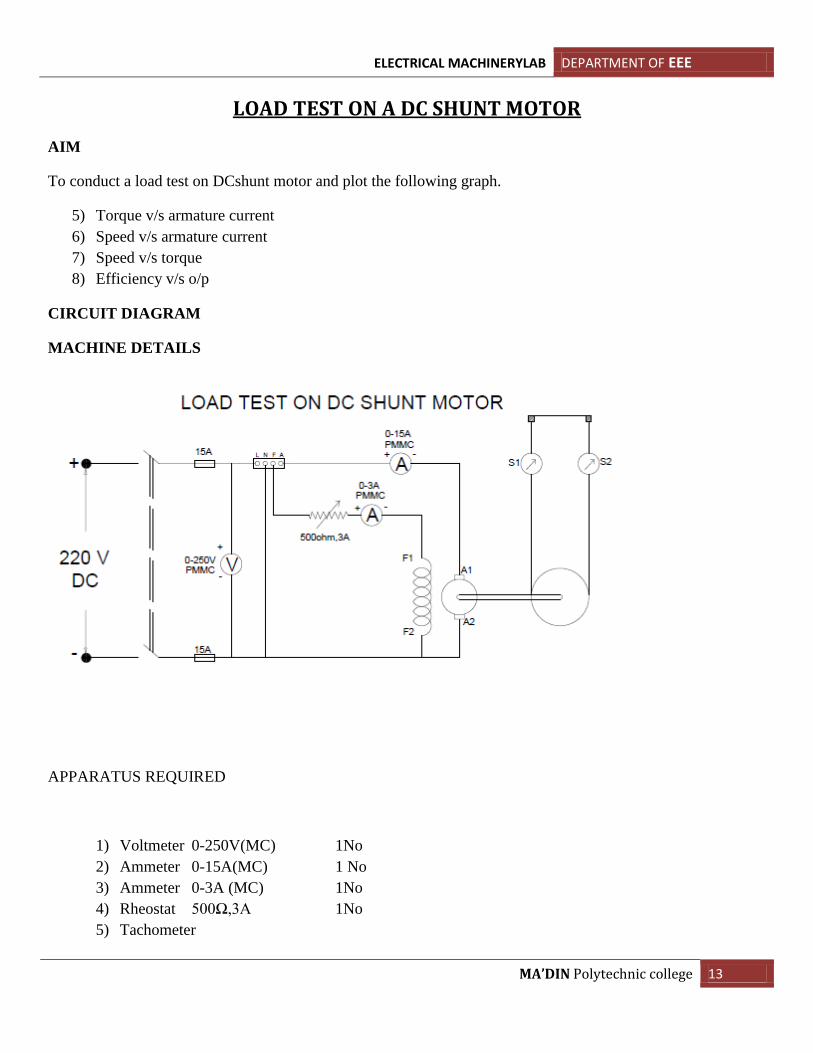
LOAD TEST ON A DC SHUNT MOTOR
AIM
To conduct a load test on DCshunt motor and plot the following graph.
5) Torque v/s armature current
6) Speed v/s armature current
7) Speed v/s torque
8) Efficiency v/s o/p
CIRCUIT DIAGRAM
MACHINE DETAILS
APPARATUS REQUIRED
1) Voltmeter 0-250V(MC) 1No
2) Ammeter 0-15A(MC) 1 No
3) Ammeter 0-3A (MC) 1No
4) Rheostat 500Ω,3A 1No
5) Tachometer
ELECTRICAL MACHINERYLAB DEPARTMENT OF EEE
MA’DIN Polytechnic college 14
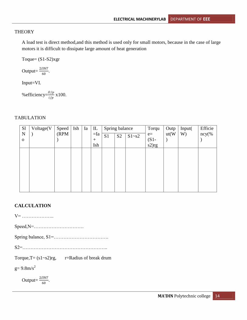
THEORY
A load test is direct method,and this method is used only for small motors, because in the case of large
motors it is difficult to dissipate large amount of heat generation
Toque= (S1-S2)xgr
Output= 2П𝑁𝑇
60.
Input=VI.
%efficiency=𝑂/𝑝
𝑖/𝑝 x100.
TABULATION
Sl
N
o
Voltage(V
)
Speed
(RPM
)
Ish Ia IL
=Ia
+
Ish
Spring balance Torqu
e=
(S1-
s2)rg
Outp
ut(W
)
Input(
W)
Efficie
ncy(%
) S1 S2 S1~s2
CALCULATION
V= ………………..
Speed,N=………………………….
Spring balance, S1=…………………………….
S2=……………………………………………..
Torque,T= (s1~s2)rg, r=Radius of break drum
g= 9.8m/s2
Output= 2П𝑁𝑇
60.
ELECTRICAL MACHINERYLAB DEPARTMENT OF EEE
MA’DIN Polytechnic college 15
%efficiency=𝑂/𝑝
𝑖/𝑝 x100.
PROCEDURE
1) Connections are made as per diagram.
2) Rheostat kept in min. position
4) Start the motor using 4 point starter
5)Note the meter readings
6) Vary the spring balance at different load.
7) Note the corresponding readings.
8) Tabulate the reading and plot the graph.
RESULT
The load test on shunt motor is conducted and plotted the graphs.
ELECTRICAL MACHINERYLAB DEPARTMENT OF EEE
MA’DIN Polytechnic college 16
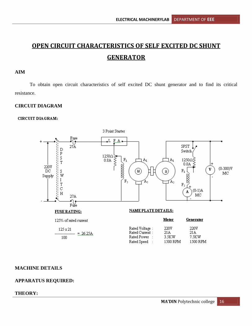
OPEN CIRCUIT CHARACTERISTICS OF SELF EXCITED DC SHUNT
GENERATOR
AIM
To obtain open circuit characteristics of self excited DC shunt generator and to find its critical
resistance.
CIRCUIT DIAGRAM
MACHINE DETAILS
APPARATUS REQUIRED:
THEORY:
ELECTRICAL MACHINERYLAB DEPARTMENT OF EEE
MA’DIN Polytechnic college 17
An electric generator is a machine, which converts mechanical energy in to electrical energy. The
energy conversion is based on the principle of the production of dynamically induced emf, whenever a
conductor cuts the magnetic flux; dynamically induced emf is produced in it according to Faraday’s laws of
electromagnetic induction. This emf causes a current to flow if the conductor circuit is closed.
Induced emf direction can be found by Flemings Right hand rule.
Self excited Generator:
Self -excited generators are those whose field magnets are energized from the
generator itself.
PROCEDURE:
1. Connections are made as per the circuit diagram.
2. After checking minimum position of motor field rheostat, maximum position of generator field rheostat,
DPST switch is closed and starting resistance is gradually removed.
3. By adjusting the field rheostat, the motor is brought to rated speed.
4. Voltmeter and ammeter readings are taken when the SPST switch is kept open.
5. After closing the SPST switch, by varying the generator field rheostat, voltmeter and ammeter readings
are taken.
6. After bringing the generator rheostat to maximum position, field rheostat of motor to minimum position,
SPST switch is opened and DPST switch is opened.
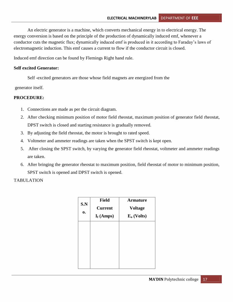
TABULATION
S.N
o.
Field
Current
If (Amps)
Armature
Voltage
Eo (Volts)
ELECTRICAL MACHINERYLAB DEPARTMENT OF EEE
MA’DIN Polytechnic college 18
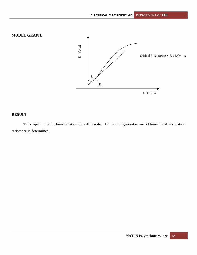
MODEL GRAPH:
RESULT
Thus open circuit characteristics of self excited DC shunt generator are obtained and its critical
resistance is determined.
Eo
If
Critical Resistance = Eo / If Ohms E o (
Vo
lts)
If (Amps)
ELECTRICAL MACHINERYLAB DEPARTMENT OF EEE
MA’DIN Polytechnic college 19
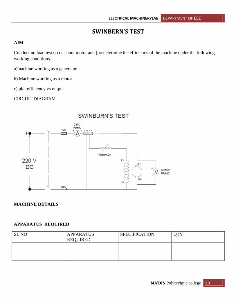
SWINBERN’S TEST
AIM
Conduct no load test on dc shunt motor and [predetermine the efficiency of the machine under the following
working conditions.
a)machine working as a generator
b) Machine working as a motor
c) plot efficiency vs output
CIRCUIT DIAGRAM
MACHINE DETAILS
APPARATUS REQUIRED
SL NO APPARATUS
REQUIRED
SPECIFICATION QTY
ELECTRICAL MACHINERYLAB DEPARTMENT OF EEE
MA’DIN Polytechnic college 20
THEORY
This is a no load test to determine the losses of the machine. the losses in the motors are
Iron loss or core losses, frictional losses, windage losses, arm copper losses
Work as generator
Efficiency= 𝑜𝑢𝑡𝑝𝑢𝑡
𝑜𝑢𝑡𝑝𝑢𝑡 −𝑙𝑜𝑠𝑠𝑒𝑠
Work as motor
Efficiency = 𝑖𝑛𝑝𝑢𝑡 −𝑙𝑜𝑠𝑒𝑠
𝑖𝑛𝑝𝑢𝑡
PROCEDURE
1. Connection are as shown in connection diagram.
2. Armature rheostat at maximum position.
3. Field rheostat at minimum position.
4. Switch on the supply and run the motor at no load.
5. Adjust the field rheostat bring motor speed to rated speed.
6. Note the readings and tabulate the readings
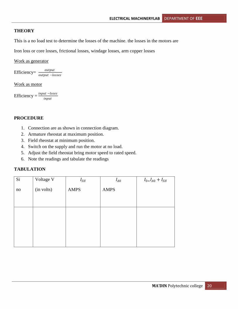
TABULATION
Si
no
Voltage V
(in volts)
𝐼𝑆𝐻
AMPS
𝐼𝐴0
AMPS
𝐼0=𝐼𝐴0 + 𝐼𝑆𝐻
ELECTRICAL MACHINERYLAB DEPARTMENT OF EEE
MA’DIN Polytechnic college 21
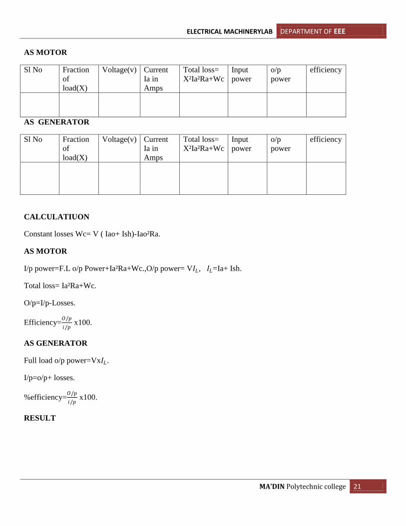
AS MOTOR
Sl No Fraction
of
load(X)
Voltage(v) Current
Ia in
Amps
Total loss=
X²Ia²Ra+Wc
Input
power
o/p
power
efficiency
AS GENERATOR
Sl No Fraction
of
load(X)
Voltage(v) Current
Ia in
Amps
Total loss=
X²Ia²Ra+Wc
Input
power
o/p
power
efficiency
CALCULATIUON
Constant losses Wc= V ( Iao+ Ish)-Iao²Ra.
AS MOTOR
I/p power=F.L o/p Power+Ia²Ra+Wc.,O/p power= V𝐼𝐿, 𝐼𝐿=Ia+ Ish.
Total loss= Ia²Ra+Wc.
O/p=I/p-Losses.
Efficiency=𝑂/𝑝
𝑖/𝑝 x100.
AS GENERATOR
Full load o/p power=Vx𝐼𝐿.
I/p=o/p+ losses.
%efficiency=𝑂/𝑝
𝑖/𝑝 x100.
RESULT
ELECTRICAL MACHINERYLAB DEPARTMENT OF EEE
MA’DIN Polytechnic college 22
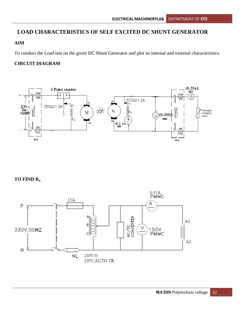
LOAD CHARACTERISTICS OF SELF EXCITED DC SHUNT GENERATOR
AIM
To conduct the Load test on the given DC Shunt Generator and plot its internal and external characteristics.
CIRCUIT DIAGRAM
TO FIND Ra
ELECTRICAL MACHINERYLAB DEPARTMENT OF EEE
MA’DIN Polytechnic college 23
APPARATUS REQUIRED:
SL NO APPARATUS
REQUIRED
SPECIFICATION QTY
MACHINE SPECIFICATIONS
Motor Generator
KW / HP
Volts
Amps
Speed
THEORY
An electric generator is a machine, which converts mechanical energy in to electrical energy. The energy
conversion is based on the principle of the production of dynamically induced emf, whenever a conductor cuts
the magnetic flux; dynamically induced emf is produced in it according to Faraday’s laws of electromagnetic
induction. This emf causes a current to flow if the conductor circuit is closed.
Induced emf direction can be found by Flemings Right hand rule.
Self excited Generator
SeLF -excited generators are those whose field magnets are energized from the
generator itself.
Eg = V + IaRa in volts. Where,
Eg = Generated voltage in volts.
V = Terminal voltage in volts.
Ia = Armature current in Amps.
ELECTRICAL MACHINERYLAB DEPARTMENT OF EEE
MA’DIN Polytechnic college 24
Ra = Armature resistance in ohms.
Armature current Ia = IL+ Ish in Amps. Where,
IL = Load current in Amps.
Ish = Shunt field current in Amps.
PROCEDURE:
1. Connect the circuit as per the circuit diagram.
2. Keep the motor field rheostat at minimum resistance and generator field rheostat at maximum resistance
position.
3. Adjust the motor field rheostat for rated speed of the generator (or by voltage control)
4. Fix the armature voltage of the generator to the rated voltage by adjusting the field rheostat of the
generator.
5. Close the DPSTS at the load side of the generator and increase the load in steps till the rated armature
current and at each step the readings of terminal voltage, load current, and shunt field current are noted.
6. Finally reduce the load insteps and bring the generator and field rheostat to its original position.
TO FIND Ra:
1. Connections are given as per the circuit diagram.
2. Gradually vary the loading rheostat insteps and at each step note down the corresponding voltmeter and
ammeter readings.
3. From the tabulated value calculate the average armature resistance.
ELECTRICAL MACHINERYLAB DEPARTMENT OF EEE
MA’DIN Polytechnic college 25
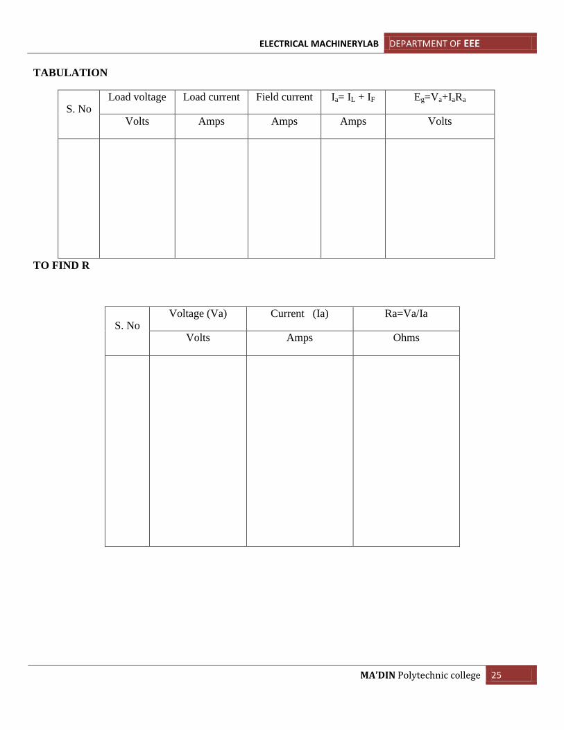
TABULATION
S. No Load voltage Load current Field current Ia= IL + IF Eg=Va+IaRa
Volts Amps Amps Amps Volts
TO FIND R
S. No Voltage (Va) Current (Ia) Ra=Va/Ia
Volts Amps Ohms
ELECTRICAL MACHINERYLAB DEPARTMENT OF EEE
MA’DIN Polytechnic college 26
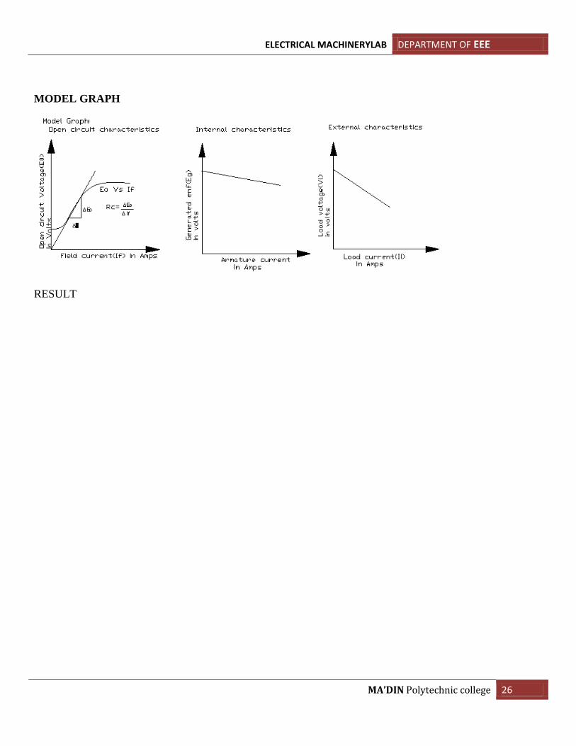
MODEL GRAPH
RESULT
ELECTRICAL MACHINERYLAB DEPARTMENT OF EEE
MA’DIN Polytechnic college 27
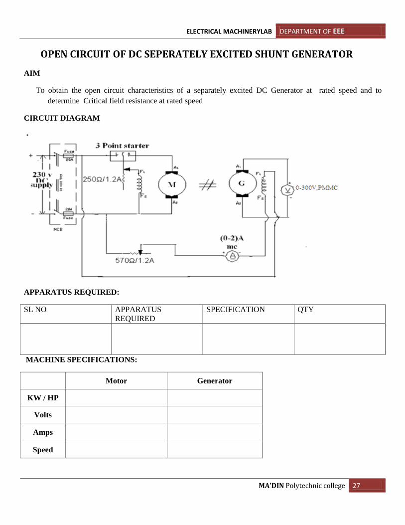
OPEN CIRCUIT OF DC SEPERATELY EXCITED SHUNT GENERATOR
AIM
To obtain the open circuit characteristics of a separately excited DC Generator at rated speed and to
determine Critical field resistance at rated speed
CIRCUIT DIAGRAM
APPARATUS REQUIRED:
SL NO APPARATUS
REQUIRED
SPECIFICATION QTY
MACHINE SPECIFICATIONS:
Motor Generator
KW / HP
Volts
Amps
Speed
ELECTRICAL MACHINERYLAB DEPARTMENT OF EEE
MA’DIN Polytechnic college 28
THEORY
An electric generator is a machine, which converts mechanical energy in to electrical energy. The
energy conversion is based on the principle of the production of dynamically induced emf, whenever a
conductor cuts the magnetic flux; dynamically induced emf is produced in it according to Faraday’s laws of
electromagnetic induction. This emf causes a current to flow if the conductor circuit is closed.
Induced emf direction can be found by Flemings Right hand rule.
Separately excited Generator:
Separately -excited generators are those whose field magnets are energized from the External power
supply.Critical field resistance, Rc = Slope of the tangent drawn to the linear portion of the OCC and passing
through origin
PROCEDURE:
1. The connections are given as per the circuit diagram.
2. Verify whether field rheostat of the generator is kept at maximum position and field rheostat of motor at
minimum position.
3. Switch ON the DC supply.
4. Adjust the excitation of field rheostat of the motor so as to make the motor to run at rated speed of the
gemerator (or by voltage control)
5. The ammeter and voltmeter readings of the generator are noted with SPSTS switch in opened position.
6. Close the SPSTS switch and excitation of the generator is varied insteps by adjusting the field rheostat
of the generator, at each step the readings of field current and induced emf are noted up to its rated
generator voltage.
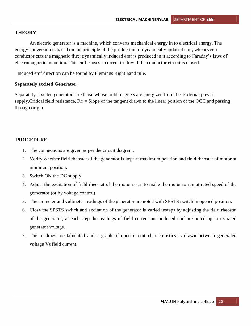
7. The readings are tabulated and a graph of open circuit characteristics is drawn between generated
voltage Vs field current.
ELECTRICAL MACHINERYLAB DEPARTMENT OF EEE
MA’DIN Polytechnic college 29
TABULATION
S. No Field current
(Amps)
Output voltage at no load
(Volts)
MODEL GRAPH
RESULT
ELECTRICAL MACHINERYLAB DEPARTMENT OF EEE
MA’DIN Polytechnic college 30
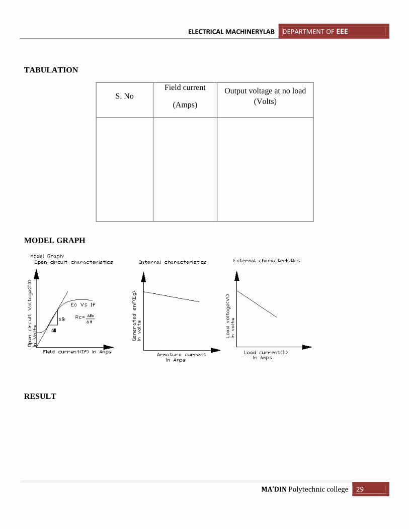
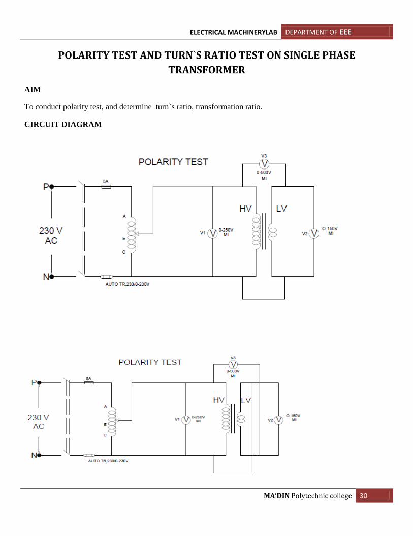
POLARITY TEST AND TURN`S RATIO TEST ON SINGLE PHASE
TRANSFORMER
AIM
To conduct polarity test, and determine turn`s ratio, transformation ratio.
CIRCUIT DIAGRAM
ELECTRICAL MACHINERYLAB DEPARTMENT OF EEE
MA’DIN Polytechnic college 31
APPARATUSREQUIRED
SL NO APPARATUS
REQUIRED
SPECIFICATION QTY
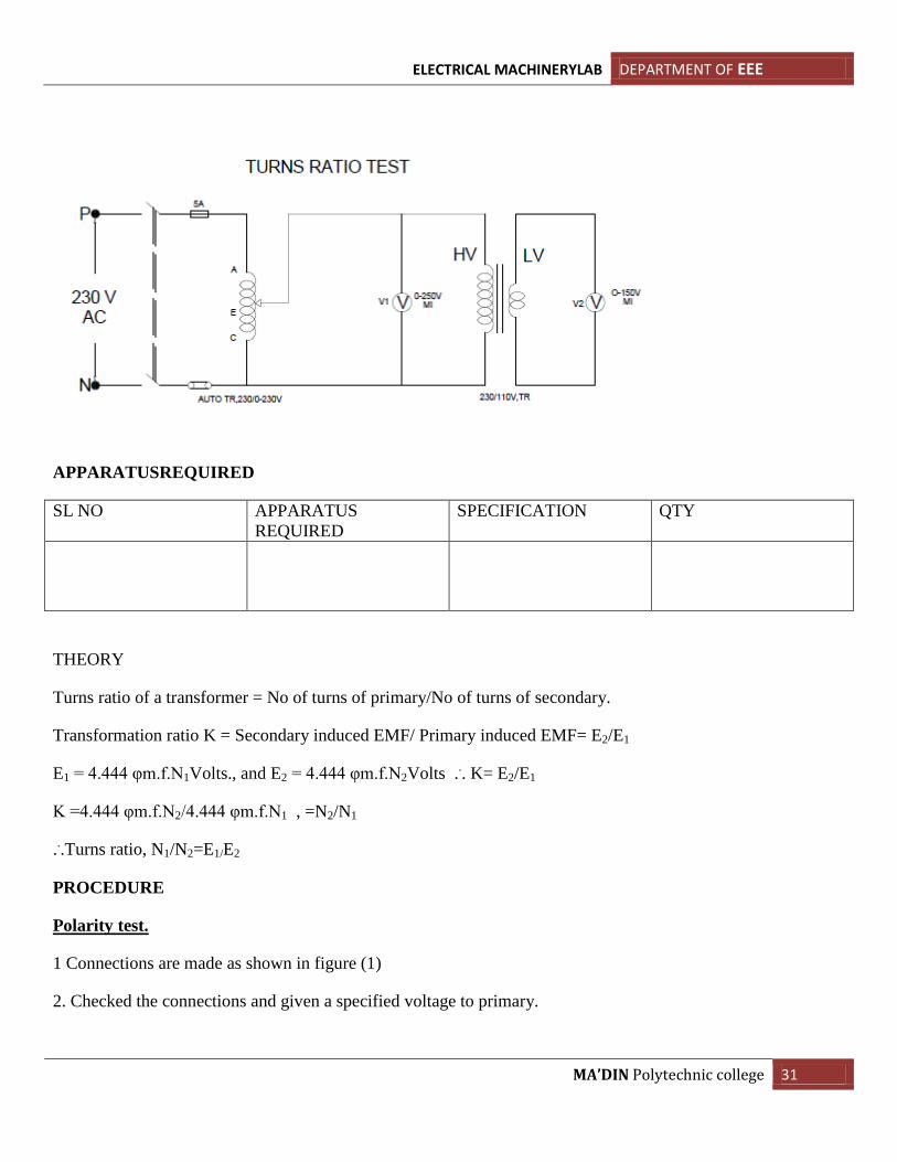
THEORY
Turns ratio of a transformer = No of turns of primary/No of turns of secondary.
Transformation ratio K = Secondary induced EMF/ Primary induced EMF= E2/E1
E1 = 4.444 φm.f.N1Volts., and E2 = 4.444 φm.f.N2Volts ... K= E2/E1
K =4.444 φm.f.N2/4.444 φm.f.N1 , =N2/N1
...Turns ratio, N1/N2=E1/E2
PROCEDURE
Polarity test.
1 Connections are made as shown in figure (1)
2. Checked the connections and given a specified voltage to primary.
ELECTRICAL MACHINERYLAB DEPARTMENT OF EEE
MA’DIN Polytechnic college 32
3. Noted the volt meter reading and verified the polarity of the transformer.ie If the voltmeter reading in the
inter connected voltmeter is greater than the input voltage, then the polarity is additive , So Opposite polarity
on the other adjacent terminal on secondary.
4. Interchanged the connections to confirm first determined polarity.
TURNS RATIO AND TRANSFORMATION RATIO TEST
1. Connections are made as in figure (2)
2. Checked the connections and given the supply gradually from minimum voltage to rated voltage of
primary using autotransformer.
3. Noted the V/m readings on primary and secondary
4. Tabulate the readings.
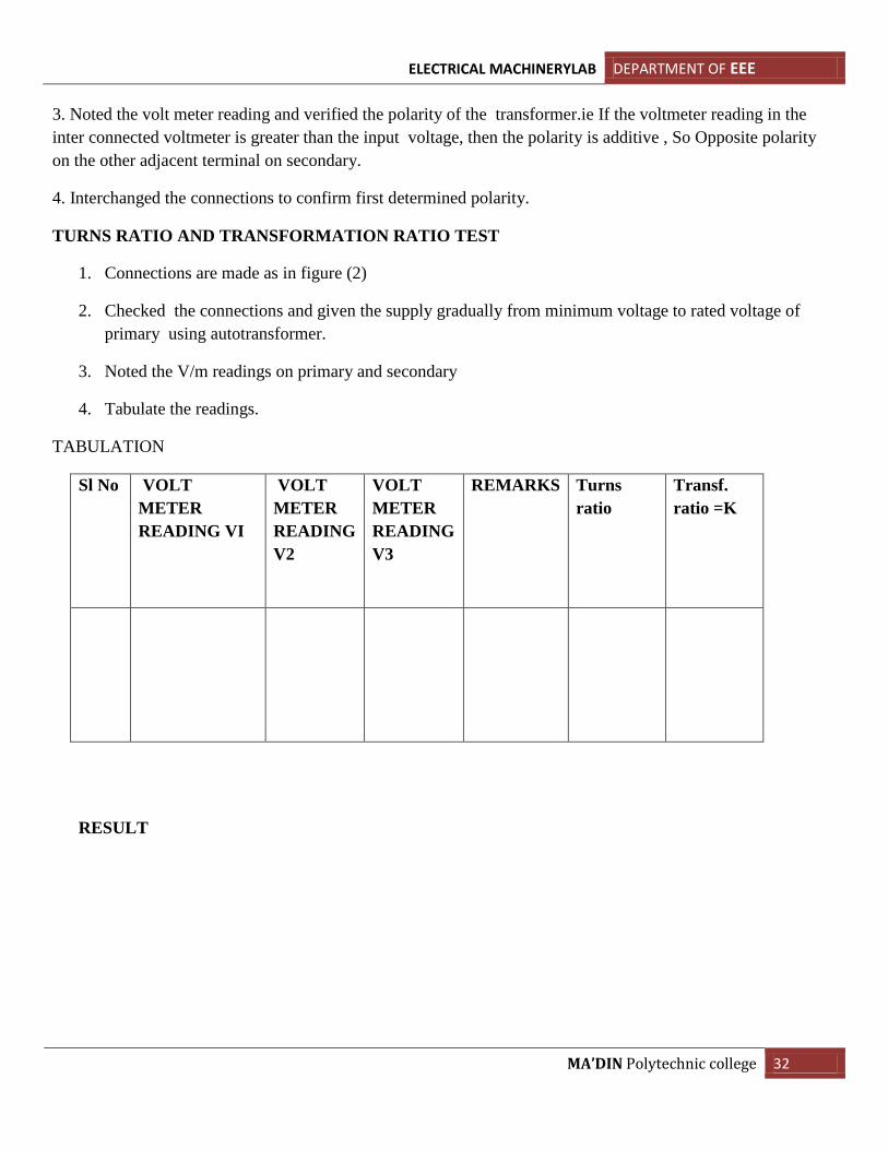
TABULATION
Sl No VOLT
METER
READING VI
VOLT
METER
READING
V2
VOLT
METER
READING
V3
REMARKS Turns
ratio
Transf.
ratio =K
RESULT
ELECTRICAL MACHINERYLAB DEPARTMENT OF EEE
MA’DIN Polytechnic college 33
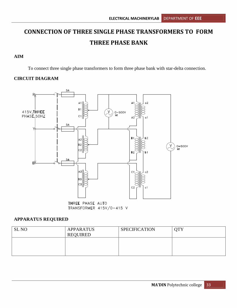
CONNECTION OF THREE SINGLE PHASE TRANSFORMERS TO FORM
THREE PHASE BANK
AIM
To connect three single phase transformers to form three phase bank with star-delta connection.
CIRCUIT DIAGRAM
APPARATUS REQUIRED
SL NO APPARATUS
REQUIRED
SPECIFICATION QTY
ELECTRICAL MACHINERYLAB DEPARTMENT OF EEE
MA’DIN Polytechnic college 34
THEORY
Interconnection of the phase winding to give a three phase ,three or four wire supply provide three
alternative modes of connection 1-mesh or delta 2-star 3-zig-zag and each of these can be achived in two ways
ie,star connection may be had by joining together A1,B1,C1 to form the neutral and using A2,B2,C2 may joined
to give neutral and A1,B1,C1 may be used as line terminal now primary and secondary can be treated in either
two ways
PROCEDURE
1. Mark the terminals of the transformer by conducting polarity test
2. Connect the ends of the primary winding in star and secondary winding in delta through a volt
meter
3. Keep the auto transformer in minimum positon and switch on the supply
4. Adjust the auto transforme to the rated voltage at the primary side
5. Check the voltmeter readings
6. If the voltmeter shows any reading it means that the system is not in balanced condition
7. In this condition,star point is of primary should be earthed and remove the voltmeter and make
the conection
8. Note the primary and secondary line voltage and primary phase voltage
9. Calculate the turns ratio
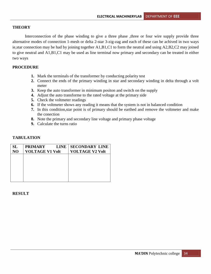
TABULATION
SL
NO
PRIMARY LINE
VOLTAGE V1 Volt
SECONDARY LINE
VOLTAGE V2 Volt
RESULT

ELECTRICAL MACHINERYLAB DEPARTMENT OF EEE
MA’DIN Polytechnic college 35